

Page 1
GE Energy
Industrial
Solutions
GEH-701 Installation Instructions
®
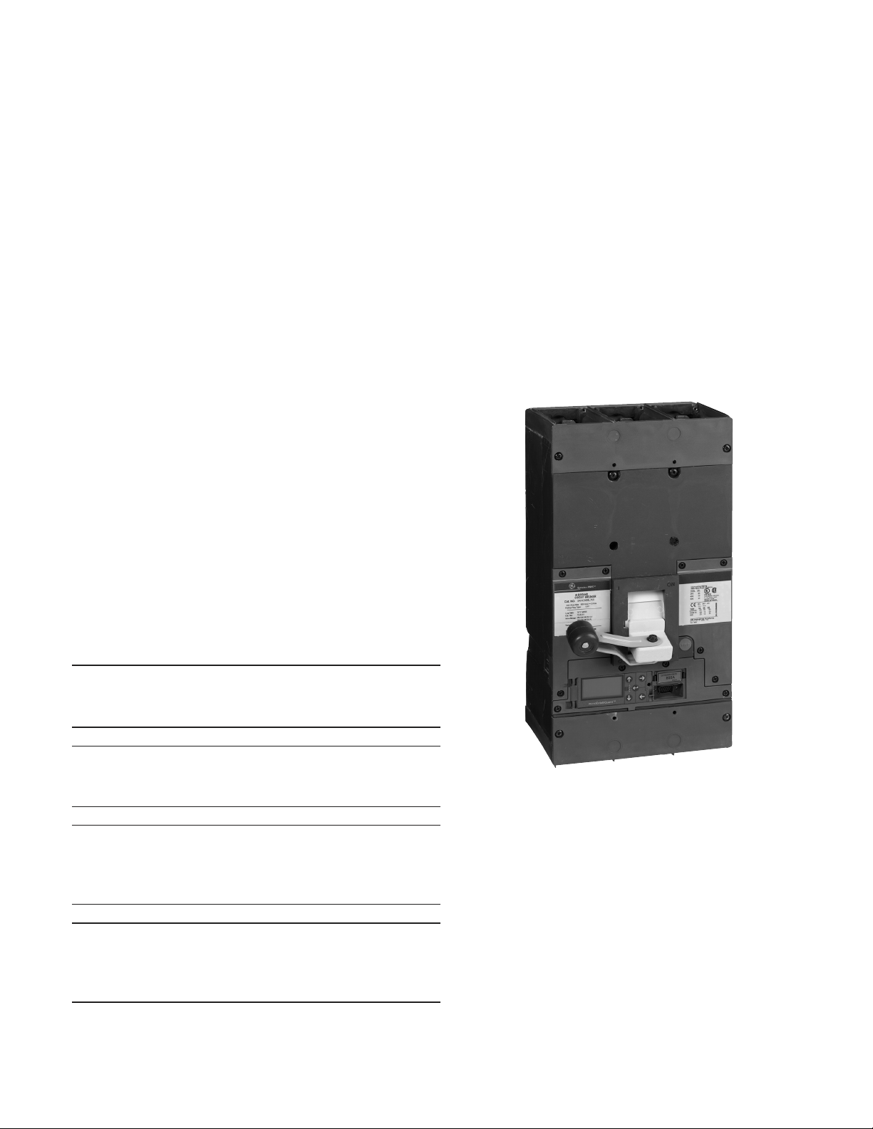
Spectra
RMS SK Frame
Molded-Case Circuit Breaker
With microEntelliGuard
Introduction
Spectra® RMS molded-case circuit breakers with
microEntelliGuard
overload and short-circuit protection for electrical
equipment. Frame
SKS are available with a selection of rating plugs
to a maximum of 1200 amperes, depending on
the sensor rating.
TM
trip units provide adjustable
types
SKH, SKL, SKP, SKT, and
SK Frame circuit breakers are listed per Underwriters
Laboratories standard UL489 and Canadian Standards
Association standard CSA22.2 No.5 and meet the
requirements of the International Electrotechnical
Commission standard IEC947-21.
WARNING: Danger of electrical shock or injury. Turn
OFF the power ahead of equipment before installing
this device or removing
any
IMPORTANT: Danger d’électrocution. Couper
l’alimentation avant d’installer cet appareil ou avant de
retirer un autre appareil.
CAUTION: This product is NOT suitable for use in
equipment not
Contact the equipment manufacturer for possible
equipment modifications.
IMPORTANT: Cet appareil ne doit pas être employé
dans un equipement qui n’est pas spécialement adapte
a cet effet. Contactez le fabricant concernant les
possibles modifications à apporter à l’équipement .
1. Spectra K Frame designated
International Electrotechincal Commission certified label.
specifically
by
SKT or SKS nomenclature will not
TM
Trip Units
other device.
designed to accept it .
carry
the
SK 1200 amp Frame breaker with
Assembly
1. Unpack the circuit breaker and inspect it for any
shipping damage. Ensure that the breaker has
the proper ampere range, sensor rating, voltage
rating, and interruption rating for the application.
Since this breaker is available in a wide
configurations, compare the catalog number of your
purchased breaker with the catalog number
Table 1. Installation of an incorrect breaker could
result in misapplication, lack of
or reduction in
system
microEntelliGuard™ Trip Unit
system
functionality.
variety
coordination,
of
key
in
Page 2
Instructions
SK (Max Amps)
Catalog Numbers
Trip Amps
GTP0300U0408
300
x
GTP0350U0408
350
x
GTP0400U0410
400
x
GTP0450U0612
450
x
x x GTP0500U0613
500
x x x
GTP0600U0616
600 x x
x
GTP0700U0816
700 x x x GTP0750U0820
750 x x
x
GTP0800U0820
800 x x x GTP0900U1020
900 x x GTP1000U1025
1000 x
x
GTP1100U1225
1100
x
GTP1200U1232
1200
x
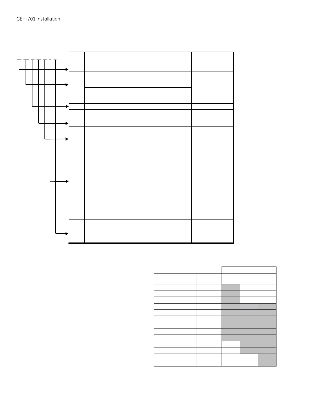
Table 1. Catalog numbering system for Spectra® RMS SK Frame breakers with
SK PC 36 12 L4 R 6
Example – a breaker with catalog number
SKPC3612L4R6 has the following features:
1 SK1200 frame (SK)
2 100 kA at 480 Vac Standard UL rating (PC)
3 3 pole, 600 Vac maximum (36)
4 1200 A sensors (12)
5 Long-time, Short-time, Instantaneous and Ground
Fault functions (L4)
6 RELT – Reduced
7 Advance Metering, Modbus Communications, and
Waveform Capture (6)
2. Following the instructions supplied with the rating
plug, install the plug into the breaker
rating plugs, with their catalog numbers, are listed in
Table 2.
1. SKT and SKS catalog codes are optimized for
480Vac maximum voltage rating.
Code Description
SK SK1200
HC
LC/TC1
PC/SC1
HH
LL/TT1
PP/SS
3, 4 or
08
10
12
L3
L4
L5
L7
X
K
Z
T
R
L
M
N
V
P
S
W
X
2
6
8
Energy
50kA at
65kA at
100kA at 480
50kA at
65kA at
1
100kA at 480
6 3 Poles, 480Vac or 600Vac
800
1000
1200
LSI
LSIG
LSIA
LSI-CP
None
Neutral
ZSI
(ST/GF)
ZSI
(ST/GF/INST)
RELT
ZSI (ST/GF)
ZSI (ST/GF) + Neutral
ZSI (ST/GF) + RELT + Neutral
RELT + Neutral
ZSI (ST/GF/INST)
ZSI (ST/GF/INST) + Neutral
ZSI (ST/GF/INST) + REL T + Neutral
Meterin g
Meterin g
Meterin g (Ad v) + Modbu s + Waveform
Meterin g (Ad v) + Modbu s + Waveform
Let-Through (R)
480Vac
480Vac
Vac
480Vac
480Vac 100% Continuous UL Rating
Vac
Amps
Amps
Amps
Protection
+ RELT
Protection
+ RELT
(Basic)
(Basic)
selectivity
Standard UL
SK
L =
S =
I = Instantaneous
G =
A =
CP = Control
Protection
Protection
Protection
+ Modbus
body.
Available
and will
Rating
Frame
Long
Time
Short
Ground
Ground Fault
Time
Fault
Alarm
Power
Protection
Capture
Capture + Protective Relays
Table 2. SK Frame Rating Plugs
carry
a
micro
EntelliGuard™ trip units
Function
Frame
Designation
Interruption
Poles, Max UL
Max
Amps
Standard
Functions
Advanced
Functions
Advanced Features
Communications
Rating
Voltage
Protection
Protection
&
800 1000 1200
Page 3
GEH-701 Instructions
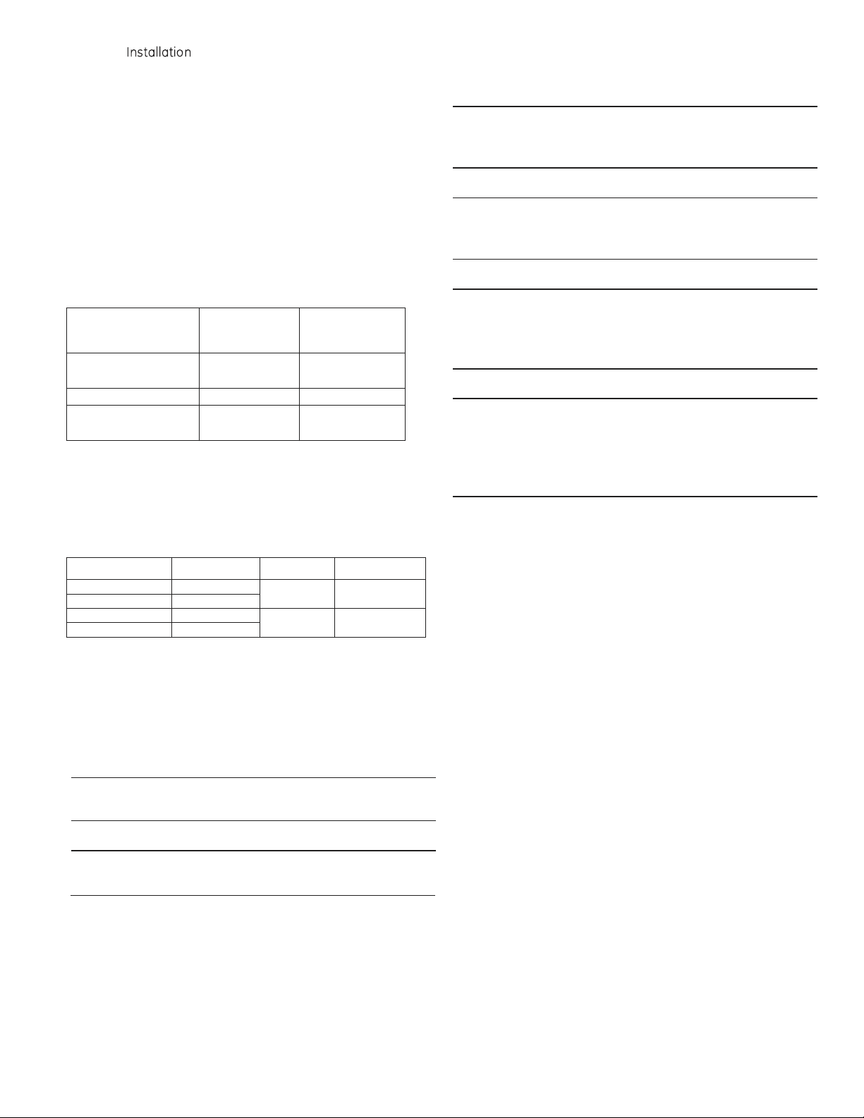
Internal Accessory
Maximum
Number
of
Ac
cessories
Ac
cessory
Insta
llati
on
Location
Auxiliary
Switch
(SPDT or DPDT)
1
R
ight
Bell Alarm Switch
1 Left
Shunt Trip or
Undervoltage
Release
1
Left
Catalog Number
Description
Wire Type
Lug Material
TCAL81
800A Lug
Cu/Al
Tin-plated
aluminum
TCAL125
1200A Lug
TCO81A
800A Lug
Cu only
Tin-plated
copper
TCO125
1200A Lug
3. Install
any
internal accessories, following the
instructions supplied with each
accessory.
Available
accessories and their mounting locations are
listed in Table 3. Check all accessories for proper
installation and wire routing.
Verify
breaker
operation with the installed accessories. Accessory
leads can be routed along the side of the breaker
and across the back. An
auxiliary
switch is required
for the breaker status signal.
Table 3. Internal Accessories
4. Attach the terminal lugs, listed in Table 4, following the
instructions supplied with the lugs.
Table 4. Available Lugs
5. Ensure that all terminals are torqued to the proper
value, as listed in the lug kit instruction sheet . Install
the terminal covers, ensuring that
seated.
NOTE: Aluminum wire must be used with a joint
compound recommended
by
the wire manufacturer.
IMPORTANT: Si un cable en aluminum est employé,
utilisez le lubrifiant recommandé par le fabricant .
they
are firmly
WARNING: It is important that the terminal covers are
installed
operation.
correctly
to ensure proper circuit breaker
IMPORTANT: Il est important de vérifier que tous
couvercles ou caches de protection sont correctement
installés afin d’assurer le bon fonctionnement de l’appareil.
NOTE: The SKP and SKS Frames (100kA , 480V) have a
longer terminal cover for the upper (line) The top portion
of this cover must be installed after cable or bus
installation. Do not substitute the shorter lug cover.
IMPORTANT: Un caches-bornes plus long est spécifique
au bout supérieur des disjoncteurs SKP et SKS (100kA ,
480V). Le haute de ce cachebarnes doit être monté après
d’installer Ie câble ou Ie bus. Ne substituez pas un cache-
bornes plus court .
6.
Finally,
required for the breaker to function
the instructions supplied with each component .
The following is a list of available associated
components:
• Terminal board connector
• Neutral current sensor connector
• Control power connector
• Extension cable
• Control power module (control power transformer
• Voltage conditioners (potential transformers may
• Voltage module
• Neutral current sensor
Mounting
All Spectra® RMS circuit breakers are suitable for
reverse feed and no line or load markings.
Incoming power cables or busbars may be
connected to either the upper or lower terminals
as required by the application
connect all associated components that are
properly,
may
be required)
be required)
using
Page 4

Instructions
Equipment
Single Branch
Series
AMC3KMFP
– Series
class 1 and 2
AMC3KMFP
800 A
SK85PK
1200A
SK125PK
– AV3, AV5
Contact Factory
Catalog Number
Application
Kit Description
SKMSK1
Mounting plate with
tapped
holes
Four
5/16-18x
1-1/4
screws and lock
washers
SKMSK2
Mounting plate with
clearance
holes
Four
5/16-18x
1-3/4
screws, nuts, and lock
washers
Enclosure
Type (1)
Catalog No.
NEMA 1 (indoor)
TK4V1200F
TK4V1200S
NEMA 3R (outdoor)
TK4V1200R
NEMA 12
(oil-tight
and dust-tight)
SG1200J
Table 6. Equipment
WARNING: Danger of electrical shock or injury. Turn
OFF the power ahead of equipment before installing
this device or removing
any
other device.
IMPORTANT: Danger de choc électrique ou de blessure.
Couper l’alimentation entrant dans l’appareil avant de
monter celui-ci ou de démonter d’autres appareils.
For individual front panel mounting:
1. Drill and tap all mounting holes and make any
necessary front-panel escutcheon cutouts, as
shown in Figure 1.
For individual mounting in a GE enclosure:
Install the breaker according to the instructions
supplied with the enclosure. Available enclosures
are listed in Table 7 (refer to the
accessories and/or
Table 7. Enclosures
Mounting
any
enclosure limitations).
Hardware Kits
BuyLog
for other
Figure 1.
Mounting
Hole and Es
cutcheon
Cutout Pattern in/(mm)
2. Mount the breaker with the hardware described in
Table 5, following the instructions supplied with the kit.
Table 5. Breaker
For GE switchboard and panelboard mounting:
Install the breaker into the equipment according to the
instructions supplied with the equipment . Available
mounting hardware kits are listed in Table 6.
Mounting
Screw Kits
Setup and Adjustment
The Spectra® RMS microEntelliGuard
digital, rms sensing, electronic trip units with an LCD
and
keypad
for viewing and/or changing the various
function settings. Refer to User’s Manual GEH-702
for detailed information concerning the operation,
adjustment, and setting of the breaker trip unit .
TM
trip units are
You should record the overcurrent protection and
protective
NOTE: Trip units as received
undesirable for the specific application. Ensure that
settings are
the breaker.
Operation
The circuit breaker status is indicated
markings, universal I/O
window that shows red for ON,
green for OFF. The corresponding handle positions are
illustrated in Figure 2. To close the breaker from the OFF
position, move the handle to the ON position. To close the
breaker from the TRIP position, first move the handle to
the OFF (reset) position, and then back to the ON position.
A Push-To-Trip button is provided for convenience in
testing the mechanical operation of the breaker.
relay
set points for future reference.
may
have settings that are
appropriately
adjusted before energizing
symbols,
and an indicator
yellow
by
ON/OFF
for TRIP, and
Page 5

GEH-701 Instructions
Figure 2. Handle
Positions
for ON, Tripped, OFF, and RESET
Maintenance
It is recommended that the following operations be
performed annually:
WARNING: Danger of electrical shock or injury. Turn
off power ahead of equipment before attempting to
service.
IMPORTANT: Danger d’électrocution. Couper
l’alimentation avant d’affectuer toute action d’entretien.
1. Turn off the power to the equipment being serviced.
2. Clean the surfaces of the breaker and surrounding
area of
3. Inspect the breaker for
4. Operate the push-to-trip button and toggle handle
several times to exercise the mechanism and test
the mechanical operation of the breaker.
5. Check all overcurrent protection and protective relay
settings for correct values as established for the
system.
6. If
has a sluggish or
display
circuit breaker.
The circuit breaker is sealed and contains no userserviceable parts. Opening the breaker will void any
and all warranties.
any
dir
t , soot , or other debris.
any
signs of damage.
any
sign of damage is found, or the mechanism
sticky
operation, or the trip unit
designates an error status, replace the
External Accessories
The following external accessories are available for
Spectra RMS SK Frame breakers. Catalog numbers
and other ordering information for these external
accessories
may
be obtained from
your
authorized GE
distributor (accessories identified with an asterisk[*]
require removal of the handle extension).
• Mounting kits
• Plug-in base, bolt-on base
• Back-connected studs
• Padlocking devices
• External Handle operator*
• Motor operators*
• Mechanical interlock*
Page 6

Instructions
Notes
Page 7

GEH-701 Instructions
Notes
Page 8

Spectra
and
microEntelliGuard
MicroVersaTrip
are
trademarks
These
instructions
provide for
operation,
problems
matter
should be referred to the GE C ompany.
do not cover all details or
every possible
or
maintenance.
arise that are not covered
contingency that
GE Energy
41
Woodford Avenue,
www.geelectrical.com
© 2013
Gene ral
Plainville,
Electric Company
imagination
are re
gistered tradem arks
of the
Should
further information
suffic iently
CT 06062
Gener al
Electric Company.
variati ons
may
be met in
for the
and
EntelliGuard
in
equ ipmen t
connection
be
desired
purchase r’s
nor do they
with
or
should
purpose s,
at work
and
installa
particular
the
tion,
GEH-701 Rev. 5 (02/13)
 Loading...