

Page 1
g
DEH40386 Installation Instructions R02
Spectra Series™ Power Panelboards
Bolt-On Circuit Breaker Kit
Catalog Numbers
AMCB6TEDL
Application
For use with circuit breaker type TED136 and current limiter
TEDL36 (015, 020, 030, 060, 100).
For Use with Circuit Breaker Cover Kit Catalog Number
AFP3TED.
Replacement Hardware Kit Number AHKBTEDL1.
Installation
WARNING: Danger of electrical shock or injury.
Turn OFF power ahead of the panelboard or
switchboard before working inside the equipment or
removing any component. Equipment i s to be
installed and maintained by properly trained and
qualified personnel only.
In the following instructions and figures, numbers in brackets
refer to the items in Table 1.
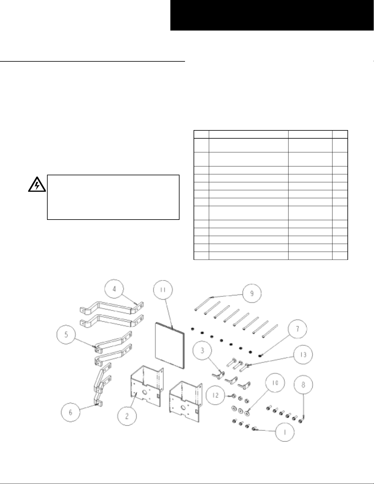
1. Confirm the contents of the kit. This kit is used to install a
TED-frame SPECTRA br anch circuit breaker with a TEDL
current limiter into a SPECTRA APNB bolt-on style interior.
The vertical space required for each kit is 4.125 inch (3X).
Refer to instruction sheet GEH-4671, supplied with the
TEDL current limiter, for installation of the current limiter to
the breaker. Figure 1 shows all the parts included in this kit,
which are listed in Table 1.
Item Description Part # Qty.
Thread-forming screw,
1
10-32x7/16"
Circuit breaker and current
2
limiter mounting bracket
3 Antiturn clip 252B3613P1 3
4 A & C phase strap 252B3618G1 2
5 A & C phase strap 252B3618G2 2
6 B phase strap 252B3618G3 2
7 Cupwasher, #8 254V644P1 8
Shakeproof screw,
8
#10-32x
9 Screw, #8-32 x 31/8" 264V322P2 8
10 Conical spring washer, 1/8" 75A105503P101 3
11 Instruction sheet DEH40386 1
12 Nut, 1/4-20 N245P21B6 3
13 Carriage bolt, 1/4-20 x 11/2" N657P21024B6 3
1
/2"
Table 1. Parts list for kit AMCB6TEDL.
192A6976P189 4
252B3573P3 2
264V291P3 6
Figure 1. Parts included in the circuit breaker mounting kit AMCB6TEDL.
Page 2
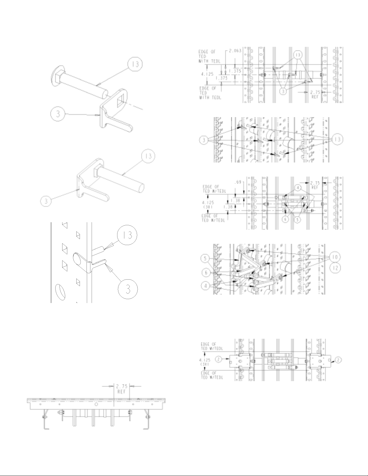
2. Assemble the antiturn clips onto the carriage bolts. Slide
the antiturn clip [3] over the corresponding square shank
of the carriage bolt [13], as shown in Figures 2a and 2b.
Install these parts onto the interior bus bars, as shown in
Figure 2c.
Figure 2a. Sliding the antiturn clip over the carriage bolt.
4. Mount the strap assembly. Position the carriage bolt and
antiturn clip assembly from step 2 as shown in Figures 4a
and 4b. Place the straps [4, 5, 6] as shown in Figures 4c
and 4d. Leave the connection finger-tight at this time.
Figure 4a. Carriage bolt and antiturn clip assembly.
Figure 4b. Isometric view of Figure 4a.
Figure 2b. Antiturn clip in position on the bolt.
Figure 2c. Carriage bolt and clip installed on the interior bus bar.
(Note that this is an isometric view from the left.)
3. Locate the proper side of the interior to mount the straps.
Locate the side of the panel interior bus at which the
distance from the vertical bus face to the inner face of the
bus support rail is 2.75 inches, as shown in Figure 3. The
circuit breaker straps will be mounted on this side of the
vertical bus. The assembly views show the 2.75-inch
distance on the right. When the 2.75-inch distance is on
the left, the proper view is upside down.
Figure 4c. Installing the straps.
Figure 4d. Isometric view of Figure 4c.
5. Install the circuit breaker mounting bracket. Fasten the
circuit breaker mounting bracket [2] to the panel side rail
using the thread-forming screws [1], as shown in Figures
5a and 5b. Tighten the thread-forming screws to 30 in-lb.
Figure 5a. Mounting bracket installation.
Figure 3. Locating the proper side of the interior to mount the straps.
Page 3

Figure 5b. Isometric view of Figure 5a.
6. Install the circuit breakers and current limiters. Since
these assemblies are for branch operations, mount the
breaker so that the line or ON-side terminals rest on the
straps and the opposite side rests on the mounting bracket.
Align the holes in the circuit breaker housing with the
corresponding holes in the mounting bracket. Fasten the
breaker to the bracket with the machine screw [7] and
washer [9], and tighten to 50 in-lb. Join the circuit
breaker terminals to the threaded holes in the straps with
the shakeproof #10-32 screws [8]. Tighten each terminal
connection to 75 in-lb. The straps may require minor
adjustments for proper alignment of the mounting holes.
7. Tape unused straps. Apply multiple wrappings of
insulation to the unused strap contact surfaces, as shown
in Figure 7. A UL or CSA Recognized 105° C
thermoplastic tape (OANZ2) is required. Overlap more
than one-half of the preceding turns, as shown, to achieve
a minimum tape thickness of 0.028 inch. This insulation
thickness requires two complete layers of overlapping
turns.
8. Tighten the bolted connections. Tighten the bolted strap
connections at the vertical bus to 65 in-lb. It may be
necessary to remove an adjacent circuit breaker to allow
access to the bolted connections at the vertical bus.
Figure 6. Mounting the circuit breakers and current limiters.
Page 4

Figure 7. Taping unused straps.
g
p
These instructions do not cover all details or variations in equipment nor do they provide for every possible contingency that
may be met in connection with installation, operation, or maintenance. Should further information be desired or should
articular problems arise that are not covered sufficiently for the purchaser’s purposes, the matter should be referred to the
GE Company.
GE Industrial Systems
General Electric Company
41 Woodford Ave., Plainville, CT 06062
DEH40386 R01 0401 © 2001 General Electric Company
 Loading...