

Page 1
g
DEH047 Installation Instructions R02
Spectra Series™ Power Panelboards
Bolt-On Circuit Breaker Kits
Catalog Numbers AMCB6EB, AMCB4SE, AMCB4EB
Application
For use with circuit breaker types TEB, TED, THED, SED,
SEH, SEL, SEP.
For Use with Circuit Breaker Cover Kit Catalog Numbers
AFP3SED, AFP4SED, AFP2TED, AFP3TED.
Installation
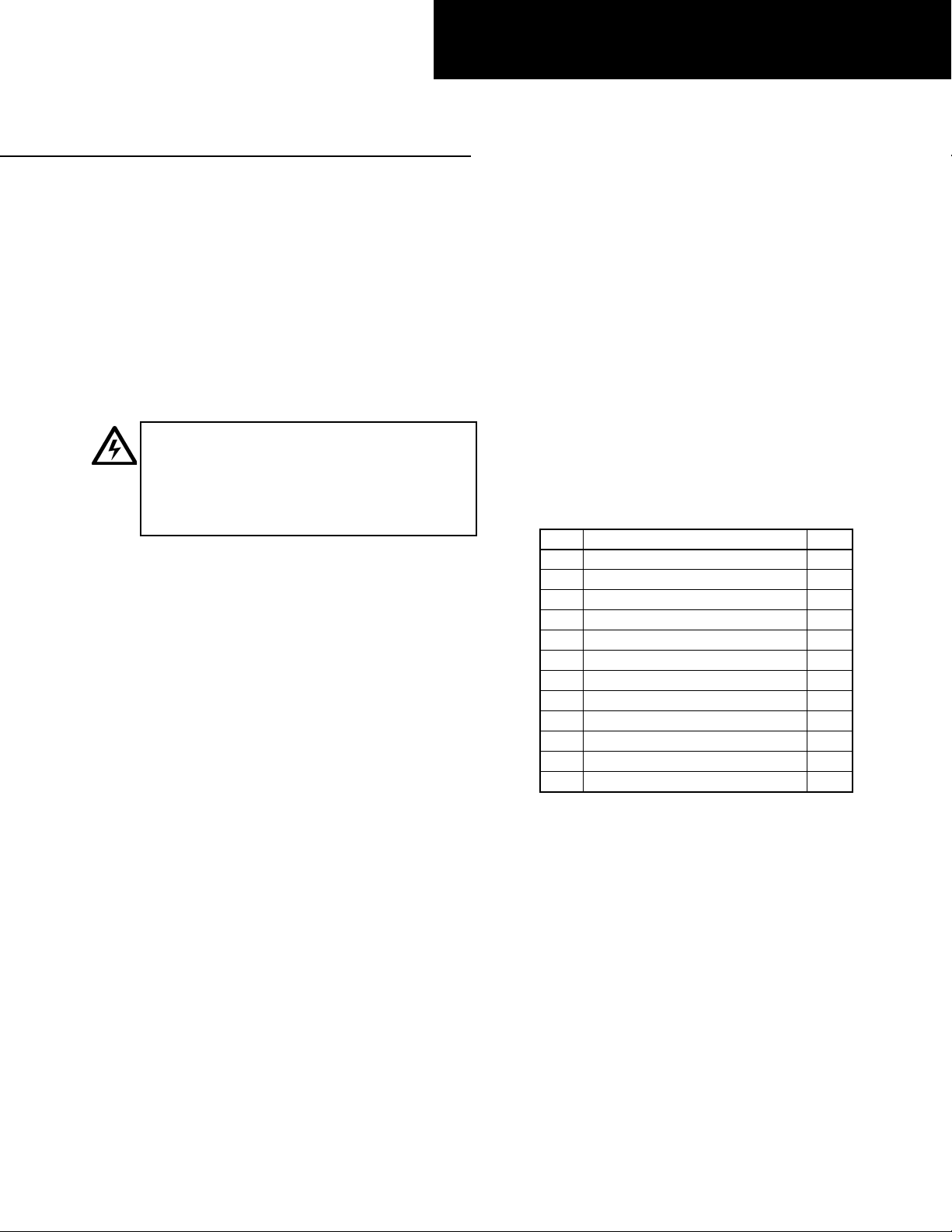
WARNING: Danger of electrical shock or injury.
Turn OFF power ahead of the panelboard or
switchboard before working inside the equipment or
removing any component. Equipment is to be
installed and maintained by properly trained and
qualified personnel only.
In the following instructions and figures, numbers in brackets
refer to the items in Table 1.
For Spectra APNB bolt-on–style interiors, locate the side of the
panel interior for which the dimension from the nearest vertical
bus face to the inner face of the bus support rail is 2.75 inches,
as indicated in Figure 2. The circuit breaker straps will be
mounted on this side of the bus.
1. Install Circuit Breaker Straps. Install the straps beginning
with the outermost (A and C) poles, as shown in Figure 1.
Align the straps [1, 2] back to back , a s shown. Slide the
square hole in the antiturn clip [12] over the corresponding
square shank of the carriage bolt [3], then insert the pin
section of the clip through the circular hole in the strap
assembly, with the carriage bolt extending through the
square hole immediately below. Fasten the complete strap
assembly loosely to the vertical bus, using a Belleville
washer [4] and nut [5] . Repeat the procedure for the
opposite pole, leaving 1.38 inches (1X) of space for the
center pole (see Table 2 for one- and two-pole connection
combinations). Align the center-pole straps [6] as shown
and fasten them loosely to the vertical bus using the same
clip, bolt, washer, and nut assembly.
2. Install Circuit Breaker Mounting Straps and Cover
Supports. Fasten the circuit breaker mounting brackets [7]
to the panel side rails using the thread-forming screws [8]
provided, as shown in Figure 1. Tighten the threadforming screws to 25 inch-pounds. Using the uppermost slot
on each cover support body, slide the cover supports
(included in the circuit breaker cover kit), with their
mounting tabs oriented inward, onto each bracket until
they snap into pl ace. The cover supports can be easily
removed by inserting a screwdriver into the mounting slot
on the underside of the mounting bracket assembly and
gently prying downward while pushing off the cover
support.
3. Install Circuit Breakers. Position the circuit breakers such
that the line- or ON-side terminals rest on the straps and
the opposite sides are supp orted by the mounting brackets.
Align the holes in each circuit breaker body with the
corresponding holes in the mounting bracket. Fasten the
breakers to the brackets with the sh eet- metal screws [10]
and cup washer s [11] and tighten to 20 inch-pounds. Join
the line-side circuit breaker terminals to the threaded holes
in the straps using the screws [9] provided. Tighten the
line-side screws to 32 inch-pounds. Note that the straps
may require minor adjustments for proper hole alignment.
4. Tighten Bolted Connections. Tighten the bolted strap
connections at the vertical bus to 65 inch-pounds. It may be
necessary to remove the adjacent circuit breakers to allow
access to the bolted connections at the vertical bus.
Item Description Qty.
1 A & C pole outer straps 2
2 A & C pole inner straps 2
31/4-20 x 1.50" carriage bolts 3
41/4" Belleville washers 3
51/4-20 hex nuts 3
6 B-pole straps 2
7 Breaker mounting brackets * 2
8 Thread-forming screws 4
9 Screws with lockwashers 6
10 8-32 x 23/4" screws 4
11 #8 cup washers 4
12 Antiturn clips 3
* Kit AMCB4EB uses an alternate 2X mounting bracket.
Table 1. Bolt-on circuit breaker assembly parts, replacement hardware
kit catalog number AHKBE1.
Page 2
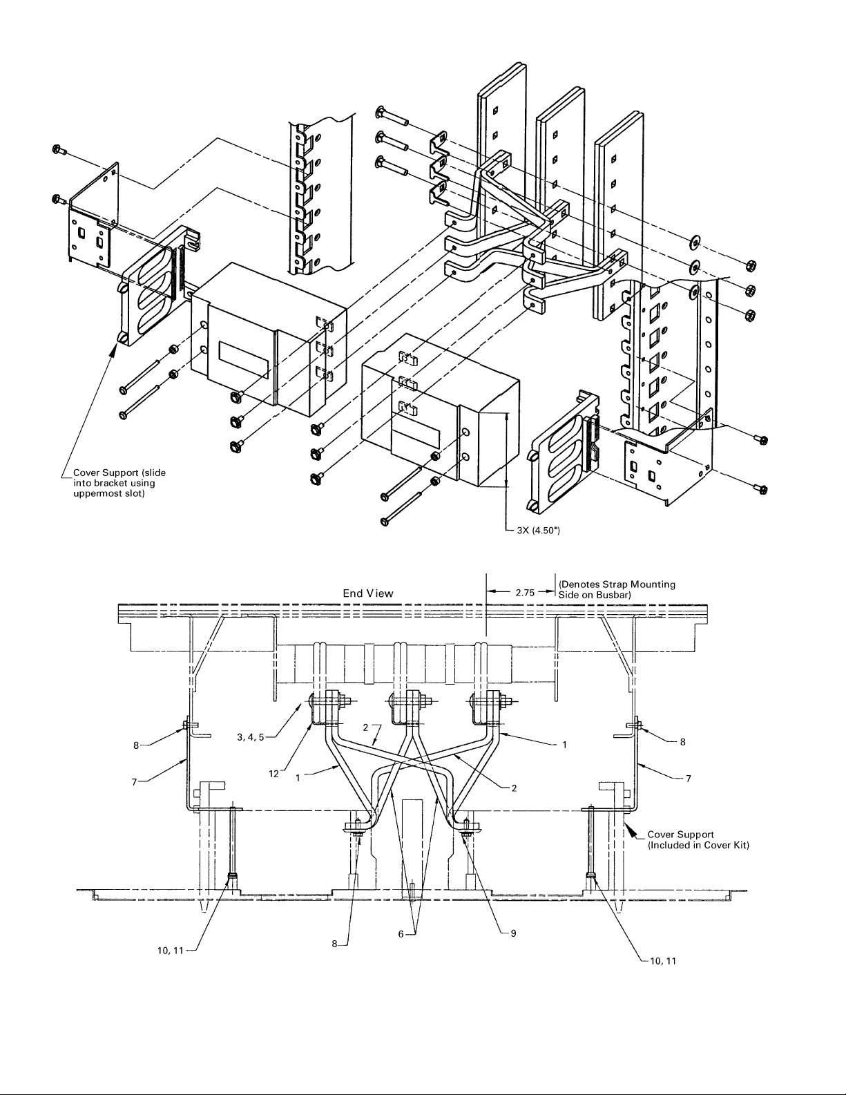
Figure 1. Bolt-on circuit breaker assembly exploded view.
Figure 2. Bolt-on circuit breaker assembly end view.
Page 3

Single- and Two-Pole
Configurations
For phase-balancing purposes, single-phase panels, and dc
applications, Table 2 contains the single- and two-phase
breaker mounting configurations available with each strap kit.
Apply multiple wrappings of insulation to unused strap contact
surfaces, as shown in Figure 2. A UL Recognized 10 5° C
thermoplastic tape (OANZ2) is required. Overlap greater than
one-half of preceding turns, as shown, to achieve a minimum
tape thickness of 0.013 inch.
Catalog
Number
AMCB4SE
AMCB4EB
(Single-
Pole)
AMCB4EB
(Two-Pole)
* Use for single-phase panels and dc applications.
A-Phase
Location
X
X
X
X
X*
B-Phase
Location
X
X
X
X
X
C-Phase
Location
X
X
X
X*
X
Table 2. Possible pole connection combinations with available strap
kits.
When installing the strap configurations in Table 2, be sure to
use standard phase rotation , as required. For example, when
connecting the first option in Table 2, connect pole A, followed
by pole B moving down the vertical bus. When installing a twopole and a three-pole breaker in the double- branch assembly,
arrange the straps in the typical three-pole configuration as
indicated in Figure 1. The AMCB4EB strap kit contains an
alt ernate circuit breaker mounting bracket for installing type
TEB or TED breakers in a four-pole, 2X (2 X 1.38 inches),
double- branch assembly. Secure both breakers in each branch
to the center hole in each mounting bracket and connect two of
the three strap assemblies as desired, as in Table 2.
Figure 2. Insulating unused strap contact surfaces.
Page 4

g
These instructions do not cover all details or variations in equipment nor do they provide for every possible contingency that
may be met in connection with installation, operation, or maintenance. Should further information be desired or should
particular problems arise that are not covered sufficiently for the purchaser’s purposes, the matter should be referred to the
GE Company.
GE Industrial Systems
General Electric Company
41 Woodford Ave., Plainville, CT 06062
DEH047 R02 0401 © 2001 General Electric Company
 Loading...