


MK 2006
Geely MK 2006, MK 2007, MK 2008, MK 2009, MK 2010 User Manual
...


Geely “MK” series sedans (JL7132U,JL7132HU,JL7152U,JL7152HU,JL7162U) are brand
new superior models developed by Geely Group who has fully proprietary intellectual property
rights. As a result of the three years of involvements and ef forts of the experts from Geely Automo-
bile Research Institute, these sedans reach international leading level in model design, power,
sense of comfort, safety and manufacturing technology while featured in beautiful appearance,
economy , environment protection and safety. The meaning of MK implied that Geely Automobile
has a great development from caterpillar to butterfly . W ith respect to the power, Geely “MK” series
sedans are equipped with 1.3L, 1.5L, and 1.6L EFI engines developed and manufactured by Geely
itself, and has reached “Chinese III” (Euro III) emission standard.
This manual contains a detailed description of the structures and principles, servicing and adjustment,
removal, assembling technology and matching clearance of the parts of the Geely “MK” sedans
with torque information of the bolts and nuts as well as schematic diagram for special tool operation.
This manual also introduces the transmission control system of the automatic transmission models,
vehicle electric circuits and elaborates ABS system, SRS, BOSCH M7.9.7 electronic control fuel
injection and ignition system, rear parking radar, sound, air conditioning and onboard hands-free
phone system. You can refer to this manual for the information about the regular maintenance,
servicing, adjustment, troubleshooting, removal and installation procedure, specific operations of
the “MK” sedans.
This manual covers the matching relation among the engine assembly, transmission assembly and
the vehicle, but does not have the further description of the structures and principles of the engine
and transmission assemblies and their servicing process. You can refer to the service manuals
solely prepared for engine assembly and transmission assembly for these information.
All information in this manual is based on the latest products released at the time of publication of
this manual. However, the specifications and procedures may need to be modified, and the subse-
quent change will be revealed in later versions.
This manual is prepared by Geely Automobile Research Institute under the assistance of technical
staff from Zhejiang Geely Automobile Co., Ltd and Geely International Corporation. Readers
discovering during the use of this manual the errors and careless omissions due to limited skills of
the preparers and tight schedule are encouraged and pled to contact Geely International in time for
our timely correction of the mistakes.
Foreword
Geely International Corporation
Nov . 2007

Table of Contents
Table of Contents
I
Part I General Information
Chapter 1 How to Use This Manual .................................................................................. 1-1
Chapter 2 Repair Instruction ............................................................................................. 1-3
Part II V ehicle Usage and Maintenance
Chapter 1 Brief Introduction of Geely MK ......................................................................... 2-1
Section 1 Major Functional and Technical Data of MK Series. ...................................... 2-1
Section 2 Vehicle System Configuration........................................................................ 2-3
Section 3 Main Vehicle Test Technical Specification...................................................... 2-5
Chapter 2 Usage and Maintenance of MK Series ............................................................ 2-6
Section 1 Usage of MK Series ....................................................................................... 2-6
Section 2 Maintenance Category and Content of MK Sedan..........................................2-12
Section 3 Daily Maintenance of MK Sedan.................................................................... 2-18
Part III Engine
Chapter 1 Engine Assembly ............................................................................................... 3-1
Section 1 Engine Inspection........................................................................................... 3-1
Section 2 Removal of the Engine Assembly from the Vehicle ....................................... 3- 5
Section 3 Drive Belt Replacement.................................................................................. 3 - 7
Chapter 2 Engine Mechanical ............................................................................................ 3-8
Section 1 Engine Components....................................................................................... 3-8
Section 2 Throttle Body .................................................................................................. 3-12
Section 3 Valve Clearance Adjustment .......................................................................... 3-14
Chapter 3 Fuel System ....................................................................................................... 3-15
Section 1 Check Fuel System Pressure......................................................................... 3-15
Section 2 Fuel Pump Inspection..................................................................................... 3-16
Section 3 Fuel Pump Replacement................................................................................ 3-17

Table of Contents
II
Section 4 Fuel Emission Control System ....................................................................... 3-18
Section 5 Carbon Canister Replacement....................................................................... 3-19
Chapter 4 Exhaust System ................................................................................................. 3-21
Chapter 5 Cooling System ................................................................................................. 3-22
Section 1 System Inspection .......................................................................................... 3-22
Section 2 Radiator Replacement................................................................................... 3-24
Chapter 6 Manual Transaxle Assembly ............................................................................. 3-25
Section 1 Frequent Problem Diagnosis.......................................................................... 3-25
Section 2 Vehicle Speed Sensor Replacement ............................................................. 3-26
Section 3 Manual Transaxle Replacement..................................................................... 3-27
Section 4 Transmission/Transaxle Case Oil Seal Replacement .................................... 3-28
Chapter 7 Automatic Transaxle Assembly ........................................................................ 3-29
Section 1 Frequent Problems Diagnosis........................................................................ 3-29
Section 2 Hydraulic Torque Converter and Transaxle.................................................... 3-30
Section 3 Differential Front Oil Seal (ATM) .................................................................... 3-33
Section 4 Neutral Switch Assembly................................................................................ 3-35
Part IV Chassis
Chapter 1 Transmission Control ........................................................................................ 4-1
Section 1 Introduction of Transmission Control ............................................................. 4-1
Section 2 Cable Type Transmission Control .................................................................. 4-3
Section 3 Manual Transmission Shift Mechanism.......................................................... 4-5
Section 4 Automatic Transmission Shift Mechanism...................................................... 4 -7
Chapter 2 Accelerator Pedal Device ................................................................................. 4-11
Section 1 Introduction of Accelerator Pedal................................................................... 4-11
Chapter 3 Clutch Control System ...................................................................................... 4-12
Section 1 Introduction of Clutch Centrol......................................................................... 4-12
Section 2 Clutch Pedal ................................................................................................... 4-13
Chapter 4 Propeller Shaft/Driveshaft ................................................................................ 4-17
Section 1 Propeller Shaft, Driveshaft and Transaxle ..................................................... 4-17

Table of Contents
III
Section 2 Front Driveshaft.............................................................................................. 4-19
Section 3 Front Wheel Hub ............................................................................................ 4-30
Section 4 Rear Wheel Hub and Bearing Assembly ....................................................... 4-35
Chapter 5 Front Suspension System ................................................................................ 4-38
Section 1 Front Suspension System .............................................................................. 4-38
Section 2 Front Suspension ........................................................................................... 4-40
Section 3 Front Wheel Alignment................................................................................... 4-43
Section 4 Front Strut Assembly...................................................................................... 4-46
Section 5 Front Lower Swing Arm Assembly ................................................................. 4-49
Section 6 Front Stabilizer Bar and Link Rod Assembly.................................................. 4-53
Chapter 6 Rear Suspension System ................................................................................. 4-54
Section 1 Rear Suspension System............................................................................... 4-54
Section 2 Rear Wheel Alignment ................................................................................... 4-56
Section 3 LH/RH Rear Suspension Coil Spring ............................................................. 4-57
Section 4 Rear Absorber Installation Assembly ............................................................. 4-60
Section 5 Rear Suspension Crossmember .................................................................... 4-62
Chapter 7 Wheel .................................................................................................................. 4-66
Section 1 Tire Inspection and Wheel Replacement....................................................... 4-66
Chapter 8 Power Steering System .................................................................................... 4-67
Section 1 Power Steering System.................................................................................. 4-67
Section 2 Steering Drive and Control Mechanism ......................................................... 4-69
Section 3 Steering Pipeline Component ........................................................................ 4-73
Section 4 Power Steering Gear...................................................................................... 4-75
Chapter 9 Brake System .................................................................................................... 4-79
Section 1 Brake System ................................................................................................. 4-79
Section 2 Brake Fluid ..................................................................................................... 4-81
Section 3 Brake Pedal.................................................................................................... 4-82
Section 4 Brake Master Cylinder Assembly ................................................................... 4-85
Section 5 Vacuum Booster ............................................................................................. 4-91
Section 6 Front Brake Disc............................................................................................. 4-94

Table of Contents
IV
Section 7 Rear Brake Drum............................................................................................ 4-99
Section 8 Parking Brake System.......................................................................................4-106
Part V Electric System & Accessory
Chapter 1 Starting and Charging System ......................................................................... 5-1
Section 1 Starting System (MR479Q, MR479QA, MR481QA) ...................................... 5-1
Section 2 Charging System (MR479Q, MR479QA, MR481QA) .................................... 5-3
Chapter 2 Combination Instrument System ..................................................................... 5-7
Section 1
Wiring diagram of Combination Instrument and Location of Multi-pin Plug-in Terminal
5-7
Section 2 Malfunction Symptom Table and Troubleshooting......................................... 5-10
Chapter 3 Wiper and Washer System ............................................................................... 5-21
Section 1 Wiper and Washer System Inspection........................................................... 5-21
Section 2 Replacement and Adjustment........................................................................ 5-23
Chapter 4 Light System ...................................................................................................... 5-26
Section 1 Light System Introduction............................................................................... 5-26
Section 2 Light System Malfunction Inspection ............................................................. 5-28
Section 3 Headlamp Replacement................................................................................. 5-34
Section 4 Front Fog Lamp Replacement ...................................................................... 5-35
Section 5 Rear Combination Lamp Replacement.......................................................... 5-36
Section 6 High-mounted Stop light Replacement .......................................................... 5-36
Section 7 Front Reading Lamp Replacement ................................................................ 5-37
Section 8 Rear Reading Lamp Replacement................................................................. 5-37
Section 9 License Plate Lamp Replacement ................................................................. 5-37
Chapter 5 Audio System ..................................................................................................... 5-38
Section 1 Audio System Description .............................................................................. 5-38
Section 2 Audio System Connector Terminal Layout ..................................................... 5-40
Section 3 Audio System Inspection................................................................................ 5-41
Section 4 Audio System Replacement........................................................................... 5-52
Chapter 6 SRS (Supplemental Restraint System) ............................................................ 5-54

Table of Contents
V
Section 1 SRS General Information ............................................................................... 5-54
Chapter 7 Air Conditioning System ................................................................................... 5-72
Section 1 General Information........................................................................................ 5-72
Section 2 Refrigerant...................................................................................................... 5-77
Section 3 A/C Operating Mechanism ............................................................................. 5-83
Section 4 Heater, Ventilation and Air Conditioning ........................................................ 5-86
Section 5 Layont of Air Conditioning Hose..................................................................... 5-92
Section 6 Multi-wedge belt (Connecting Compressor and Crankshaft Pulley).............. 5-93
Section 7 Compressor Assembly.................................................................................... 5-94
Section 8 Condenser Fan and Condenser Assembly.................................................... 5-96
Chapter 8 MK-60 ABS System ........................................................................................... 5-99
Section 1 ABS Diagnosis................................................................................................ 5-99
Section 2 ABS System Check ...................................................................................... 5-103
Section 3 Removal and Installation.............................................................................. 5-138
Section 2 Power Door Lock Control System ................................................................ 5-142
Part 6 Interior & Exterior Trim and Accessory
Chapter 1 Front Seat Assembly ......................................................................................... 6-1
Chapter 2 Rear Row Seat Assembly ................................................................................. 6-3
Chapter 3 Front Seat Belt ................................................................................................... 6-5
Chapter 4 Rear Seat Belt .................................................................................................... 6- 9
Chapter 5 Dashboard, Middle Console and Instrument Panel ....................................... 6-11
Chapter 6 Windshield ......................................................................................................... 6-16
Chapter 7 Rear Window Glass (with Defrosting Heater Wire) ........................................ 6-20
Chapter 8 Side Inner Panel Trim ........................................................................................ 6-22
Chapter 9 Roof Trim ............................................................................................................ 6-25
Chapter 10 Front Door Interior Trim .................................................................................. 6-27
Chapter 11 Rear Door Interior Trim ................................................................................... 6-30
Chapter 12 Front Bumper ................................................................................................... 6-33
Chapter 13 Rear Bumper .................................................................................................... 6-35

Chapter 14 Outside Rearview Mirror ................................................................................. 6-37
Chapter 15 Door Protecting Stripe .................................................................................... 6-38
Chapter 16 Carpet and Insulator ....................................................................................... 6-39
Chapter 17 Moonroof Assembly (Optional) ...................................................................... 6-40
Chapter 18 Plug List ........................................................................................................... 6-42
Part 7 Body
Chapter 1 Survey ................................................................................................................ 7-1
Section 1 Body Structure................................................................................................ 7-1
Chapter 2 Body Repair ....................................................................................................... 7-9
Section 1 Body Damage Forms and Requirements for Repair...................................... 7-9
Section 2 Typical Technique of Body Panel Repair ....................................................... 7-16
Section 3 Repair After Body Damage ............................................................................ 7-16
Section 4 Features and Composition of Automobile Body ............................................ 7-24
Section 5 Painting Techniques After Body Repair ......................................................... 7-35
Section 6 Service Data For for Body.............................................................................. 7-36
Attachment: Body Key Dimensions
Appendix: T orque Table of the Fasteners for Important Assembly
Table of Contents
VI

General Information - How to Use This Manual
1-1
Part 1 General Information
Chapter 1 How to Use This Manual
I. Instruction
1. General Information
(1)This manual conform to the first part of GB/T1.1--2000 Standardization Guide: The structure and prepar-
ing rule of the standard.
(2)Generally, the repairing job can be divided into the following 3 procedures:
1. Diagnosis
2. Removal and installation, replacement, disassembly and inspection, adjustment
3. Final inspection
(3) The first procedure “Diagnosis” (the details refers to each section or chapter) and second procedure “Re-
moval and installation, replacement, disassembly and inspection, adjustment” are scattered in the chapters and
sections, and this manual omits the third procedure “Final inspection”.
(4) This manual does not include the following basic operations which are imperative in real scenarios.
operate the jack or lifter
b. clean the removed parts if necessary.
c. inspect the appearance
2. Preparation
SST (Special Service Tools) and SSM (Special Service Materials) may be required and correctly used based
on the repairing condition, make sure the job procedure is followed.
3. Repair Procedure
(1) The disassembly illustration is placed under the title.
(2) The illustration shows the disassembly of the parts to help you understand the assembly of the parts.
(3) Non-reusable parts need to be coated with grease, and the precoated parts and torque are specially shown
in the disassembly illustration.
(4) Sometimes, the illustrations of the similar model are used where there may be some details differently
from the actual vehicle.
(5)The operational procedure is described in the following ways:
a. The illustration shows what to do and where to do it.
b. The task heading tells what to do.
c. The detailed text tells how to perform the task and gives other information such as specifications and
warnings.
4. Specification
Specifications are presented in bold type throughout the manual.
5.Term Definition
6. International System of Unit
The Units given in this manual are primarily expressed according to the International System of Unit.
Caution indicates there is a possibility of injury to you or other people.
Notice indicates the possibility of damage to the components being repaired.
Tip provides additional information to help you perform the repair efficiently.
a.
General Information - How to Use This Manual
1-2
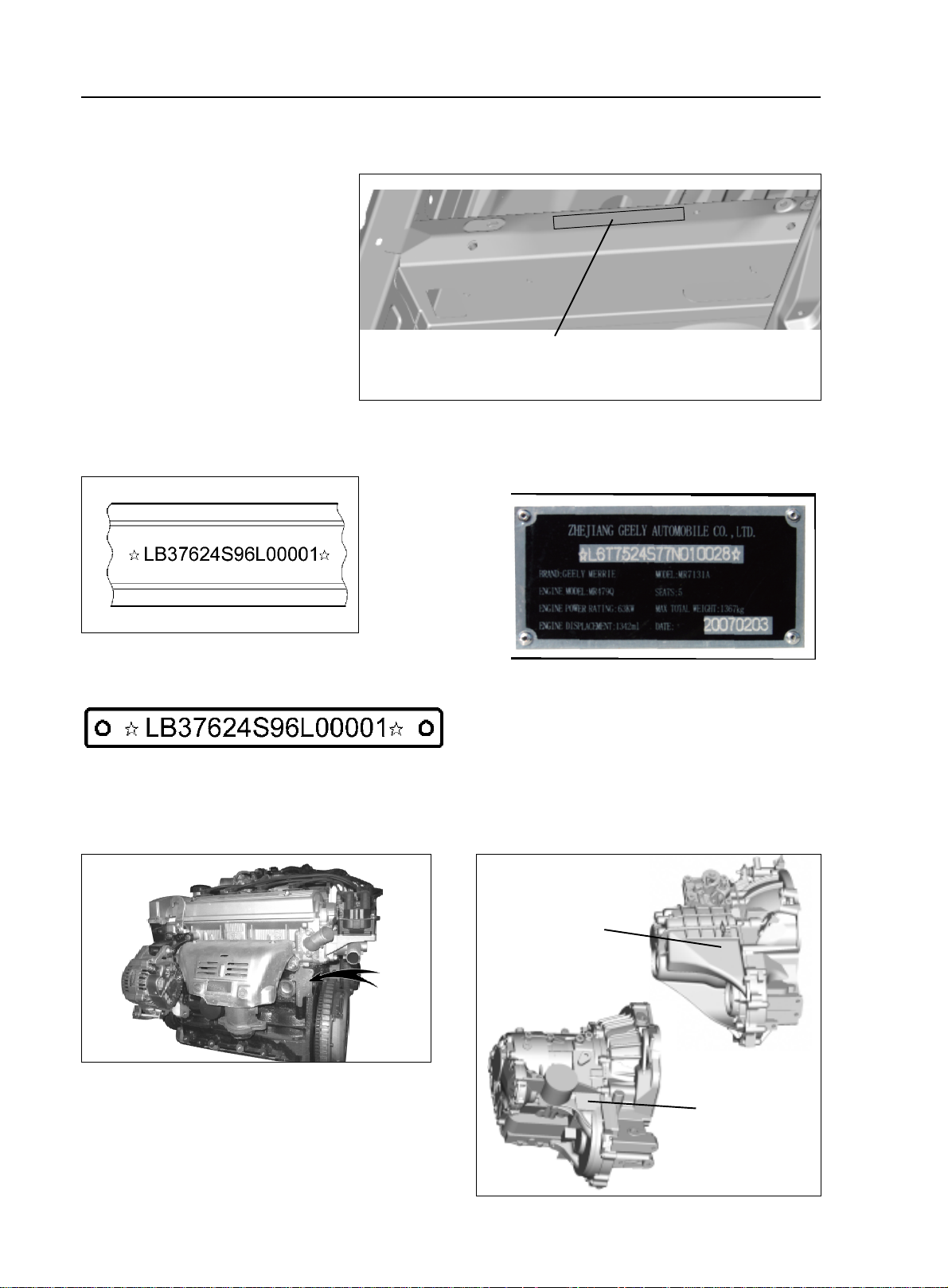
II. Vehicle Identification
1. Vehicle Identification Number
(VIN):
Vehicle Identification Number
(VIN) is the legal identification of the
vehicle which is printed on the middle
of the engine compartment cowl (as
shown in the illustration).
VIN code position
3. Ex-work Nameplate: on the middle of the engine
compartment cowl
4. VIN Code: on the left lower corner of the front windshield.
5. Engine Number:
marked on the engine block as shown in the illustration
6. Transmission Mark:
printed on the left side of the transmission
2. VIN Code
Mark position
Mark position
General Information - Repair Instruction
1-3
Chapter 2 Repair Instruction
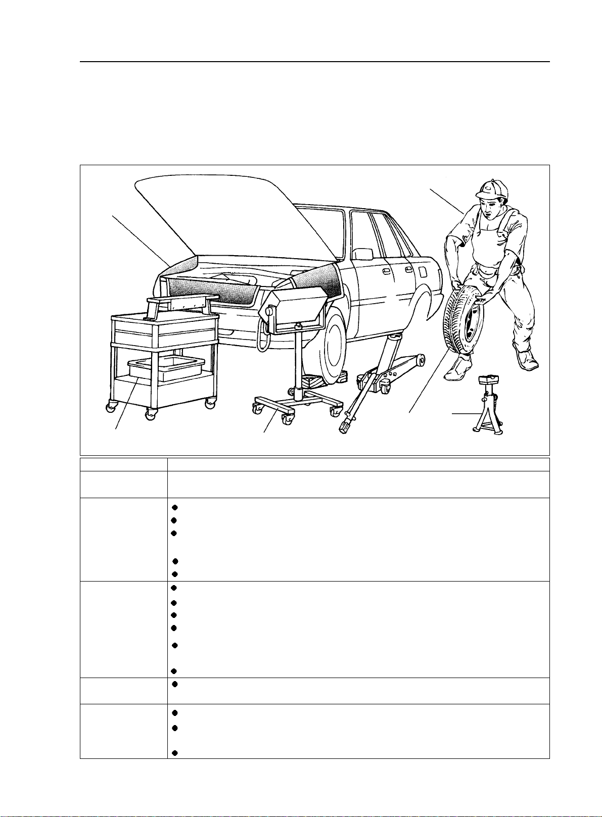
I. Precautions
1. Basic Repair Hint
(1)Operation Hint
Vehicle Protection
Appearance
Safe Operation
Removal and
installation, disas-
semble and inspection
Prepare the tools and
measuring instrument
Removed parts
Before the work, place radiator fascia cloth, fender cloth, seat cover and mat.
Always wear clean uniform
Make sure to wear the helmet and safety shoe
when more than 2 persons work together, be sure to pay mutual attention to the safety.
when it is required to run the engine, you have to pay attention to the ventilation of the workshop.
When handling the high-temperature, rotating, moving and vibrating parts, be careful not to be scalded
or hurt.
When lifting the vehicle, safety stand should be used to support the specified position.
When lifting the vehicle, safety devices should be used.
The diagnosis requires full understanding of the trouble and effective operation.
Before the parts are removed, check the assembly for distortion and damage.
The diagnosis requires full understanding of the trouble and effective operation.
Before the parts are removed, check the assembly for distortion and damage.
If the structure is complicated, notes or marks should made to avoid mistake and impact of the part
function.
If needed, clean the removed parts and reassemble them after careful inspection.
Before the work, prepare the tool fixture, special tools, instrument, oil, workshop cloth and required
parts for replacement.
arrange the removed parts in correct sequence, do not confuse or contaminate them.
For non-reusable parts such as gasket, O ring and self-locking nut, replace them with new ones in
accordance with the instruction described in this manual.
Pick up replaced parts, put them in the containers, and show them to the customers.
2
4
3
5
6
1

General Information - Repair Instruction
1-4
(2)Lift and support the vehicle
Be careful to lift and support the vehicle. Make sure that the vehicle is appropriately supported.
(3)Precoated Parts
a. Precoated parts are bolts, nuts, etc. that are coated with a seal
lock adhesive at the factory.
b. If a precoated part is retightened, loosened or caused to move
in any way, it must be recoated with the specified adhesive.
c. When reusing precoated parts, clean off the old adhesive and
dry with compressed air. Then apply the specified sealing adhesive
to the bolt, nut or threads.
Illustration Symbol Part Name
Fuse
Medium Current
Fuse
High Current Fuse
Notice: the torque should achieve the lower limit of the allowed torque range.
d. The precoated parts should be kept intact for a period of time for induration based on the requirement of
the sealing adhesive.
(4)Gasket
If necessary, apply the sealant to the gasket to prevent disclosure.
(5)Bolt, nut and screw
Be careful to follow all torque specification and torque wrench should be used.
(6)Fuse
When replacing fuses, be sure the new fuse has the correct am-
perage rating. Do not exceed the rating or use one with a lower rating.
Sealing Adhesive
Equal Rated Ampere Value
General Information - Repair Instruction
1-5
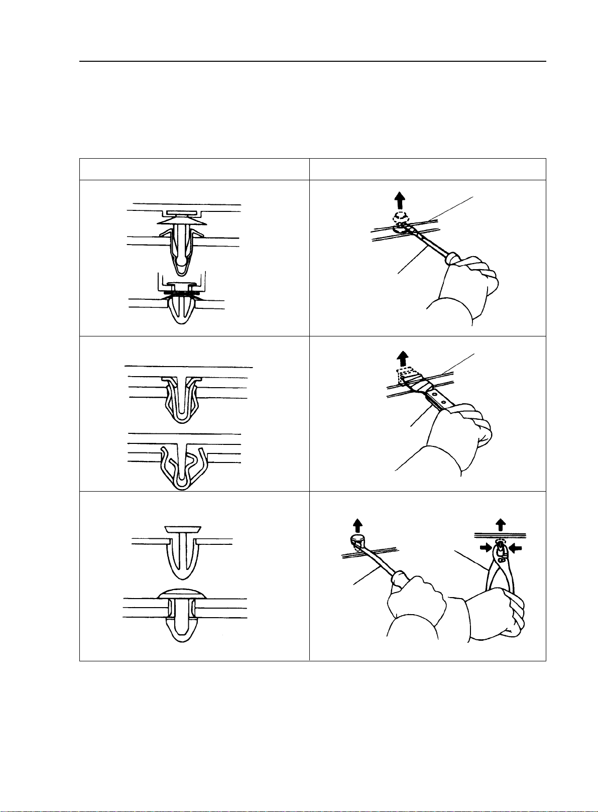
(7)Clip
The following illustration shows the typical removal and installation of the clip for body parts.
Tip:
If the clip is damaged during the operation, you have to replace it with a new one.
Illustration
Removal/installation
Clip Remover
Slip-joint
Pliers
Protective Band
Screwdriver
Protective Band
Scraper
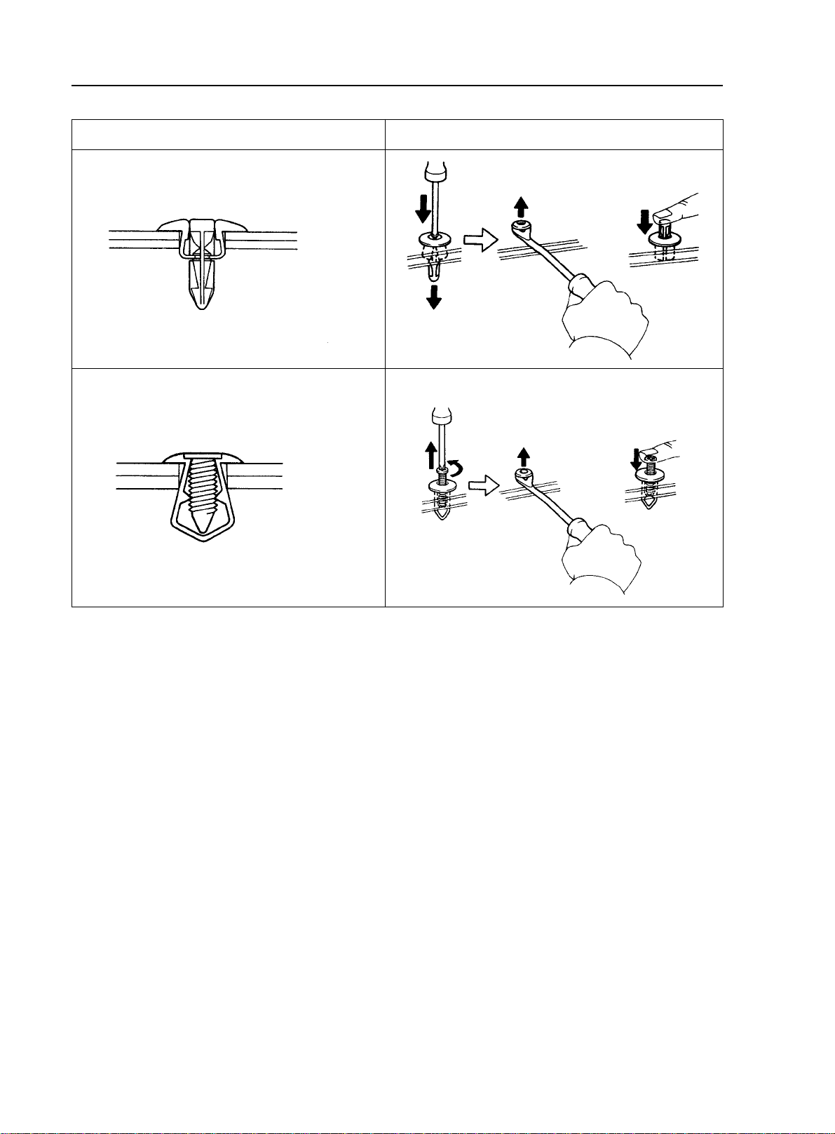
General Information - Repair Instruction
1-6
Illustration
Removal/installation
2. For Vehicles Equipped With SRS Airbag and Seat Belt Pretensioner
Tip: This is equipped with an SRS (Supplemental Restraint System), such as the driver airbag assembly,
front passenger airbag assembly airbag ECU and seat belt pretensioner. Failure to carry out service operations in
the correct sequence could cause the supplemental restraint system to unexpectedly deploy during servicing,
possibly leading to a serious accident. Further, if a mistake is made in servicing the supplemental restraint
system, it is possible the SRS may fail to operate when required. Before servicing (including removal or instal-
lation of parts, inspection or replacement), be sure to read the following items carefully, then follow the correct
procedure described in this manual.
(1) General Notice
Install
Remove
Install
Remove
a. Malfunction symptoms of the supplemental restraint system are difficult to confirm, so the diagnostic
trouble codes become the most important source of information when troubleshooting. When troubleshooting
the supplemental restraint system, always inspect the diagnostic trouble codes before disconnecting the battery.
b. Work must be started after 90 seconds from the time the ignition switch is turned to the "LOCK"
position and the negative (-) terminal cable is disconnected from the battery. (The supplemental restraint system
is equipped with a back--up power source so that if work is started within 90 seconds of disconnecting the
negative (-) terminal cable from the battery, the SRS may deploy.) When the negative (-) terminal cable is
disconnected from the battery, memory of the clock and audio systems will be cancelled. So before starting
work, make a record of the contents memorized by the each memory system. Then when work is finished, reset
the clock and audio systems as before. To avoid erasing the memory of each memory system, never use a back-
up power supply from another battery.
General Information - Repair Instruction
1-7
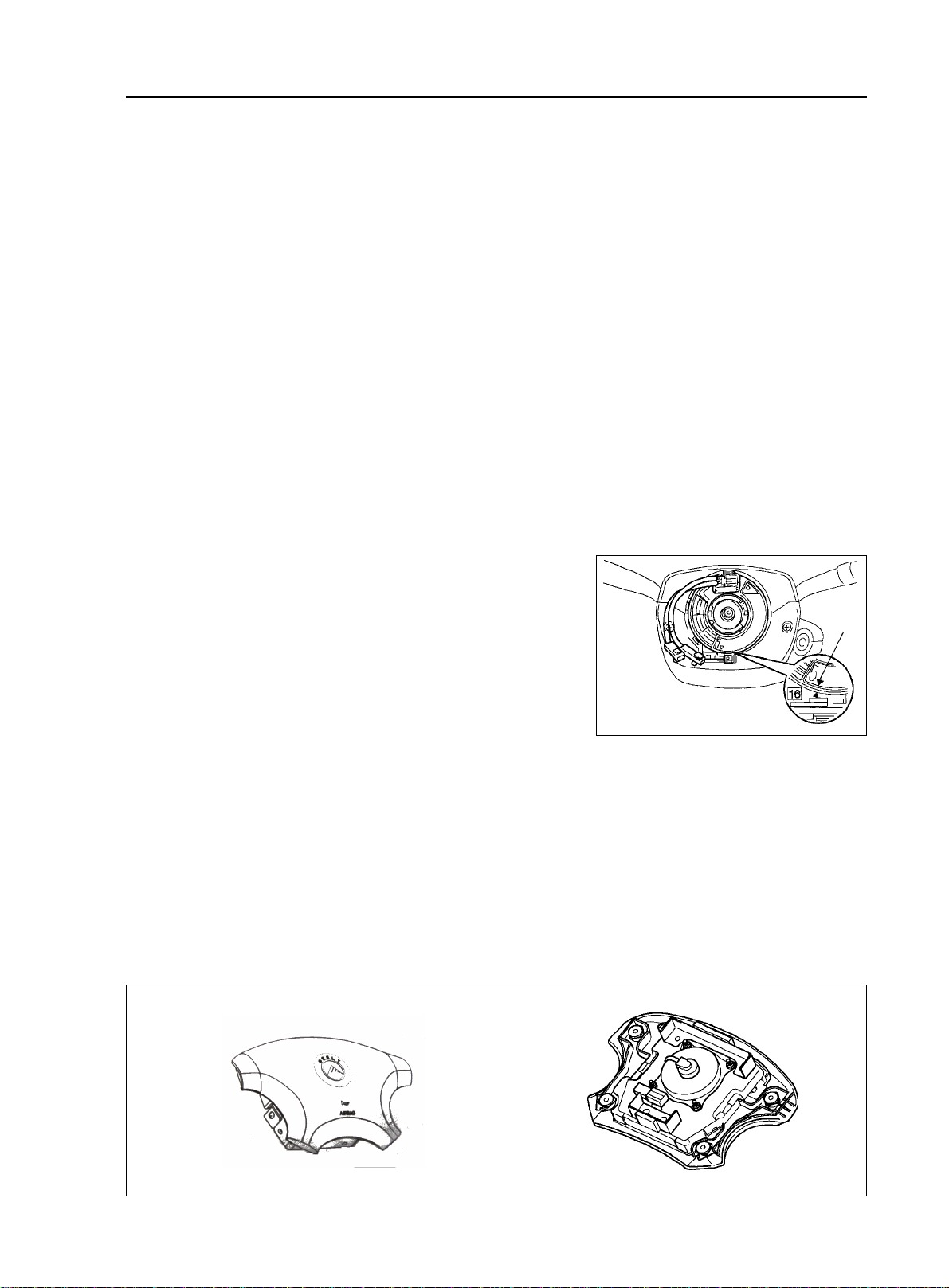
(3) Driver Airbag Assembly
a. When removing the driver airbag assembly or handling a new driver airbag assembly, it should be placed
with the steering wheel top surface facing up. Storing the steering wheel with its top surface facing downward
may lead to a serious accident if the airbag deploys for some reason. In addition do not store a driver airbag
assembly on top of another one.
b. Never measure the resistance of the airbag squib. (This may cause the airbag to deploy, which is very
dangerous.)
c. Grease should not be applied to the driver airbag assembly and the pad should not be cleaned with
detergents of any kind.
(2) Clock Spring (in combination switch)
The steering wheel must be fitted correctly to the steering col-
umn with the clock spring at the neutral position, otherwise clock
spring disconnection and other troubles may result.
c.
Even in cases of a minor collision where the SRS does not deploy, the driver airbag assembly, front
passenger airbag assembly and seat belt pretensioner should be inspected.
e.
Never use SRS parts from another vehicle. When replacing parts, replace them with new parts.
f.
Before repairs, remove the airbag ECU if shocks are likely to be applied to the sensor during repairs.
g.
Never disassemble and repair the airbag ECU assembly, driver airbag assembly, front passenger airbag
assembly or seat belt pretensioner.
h.
If the airbag ECU assembly, driver airbag assembly, front passenger airbag assembly or seat belt
pretensioner has been dropped, or if there are cracks, dents or other defects in the case, bracket or connector,
replace them with new ones.
i.
Do not directly expose the airbag ECU assembly, driver airbag assembly, front passenger airbag assem-
bly or seat belt pretensioner to hot air or flames.
j.
Use a volt/ohmmeter with high impedance (10 k ohm/ V minimum) for troubleshooting of the electrical
circuit.
Information labels are attached to the periphery of the SRS components. Follow the instructions on the
notices.
After work on the supplemental restraint system is completed, check the SRS warning light
Mark
Correct
Wrong
d.
k.
General Information - Repair Instruction
1-8
(5) Seat Belt Pretensioner
a. Never measure the resistance of the seat belt pretensioner. (This may cause the seat belt pretensioner to
activate, which is very dangerous.)
b. Never disassemble the seat belt pretensioner.
c. Never install the seat belt pretensioner in another vehicle.
d. Store the seat belt pretensioner where the ambient temperature remains below 80°C and away from
electrical noise without high humidity.
e. When using electric welding, first disconnect the connector (yellow color and 2 pins) before starting
work.
f. When disposing of a vehicle or the seat belt pretensioner alone, the seat belt pretensioner should be
activated before disposal. Perform the operation in a safe place away from electrical noise.
g. The seat belt pretensioner is hot after activation, so let it cool down sufficiently before the disposal.
However never apply water to the seat belt pretensioner.
h. There should be no oil or water on the seat belt, no cleanser should be used to wash it.
d. Store the driver airbag assembly where the ambient temperature remains below 93°C , without
high humidity and away from electrical noise.
e. When using electric welding, first disconnect the airbag connector (yellow color and 2 pins) under the
steering column near the combination switch connector before starting work.
f. When disposing of a vehicle or the driver airbag assembly alone, the airbag should be deployed using an
SST before disposal. Perform the operation in a safe place away from electrical noise.
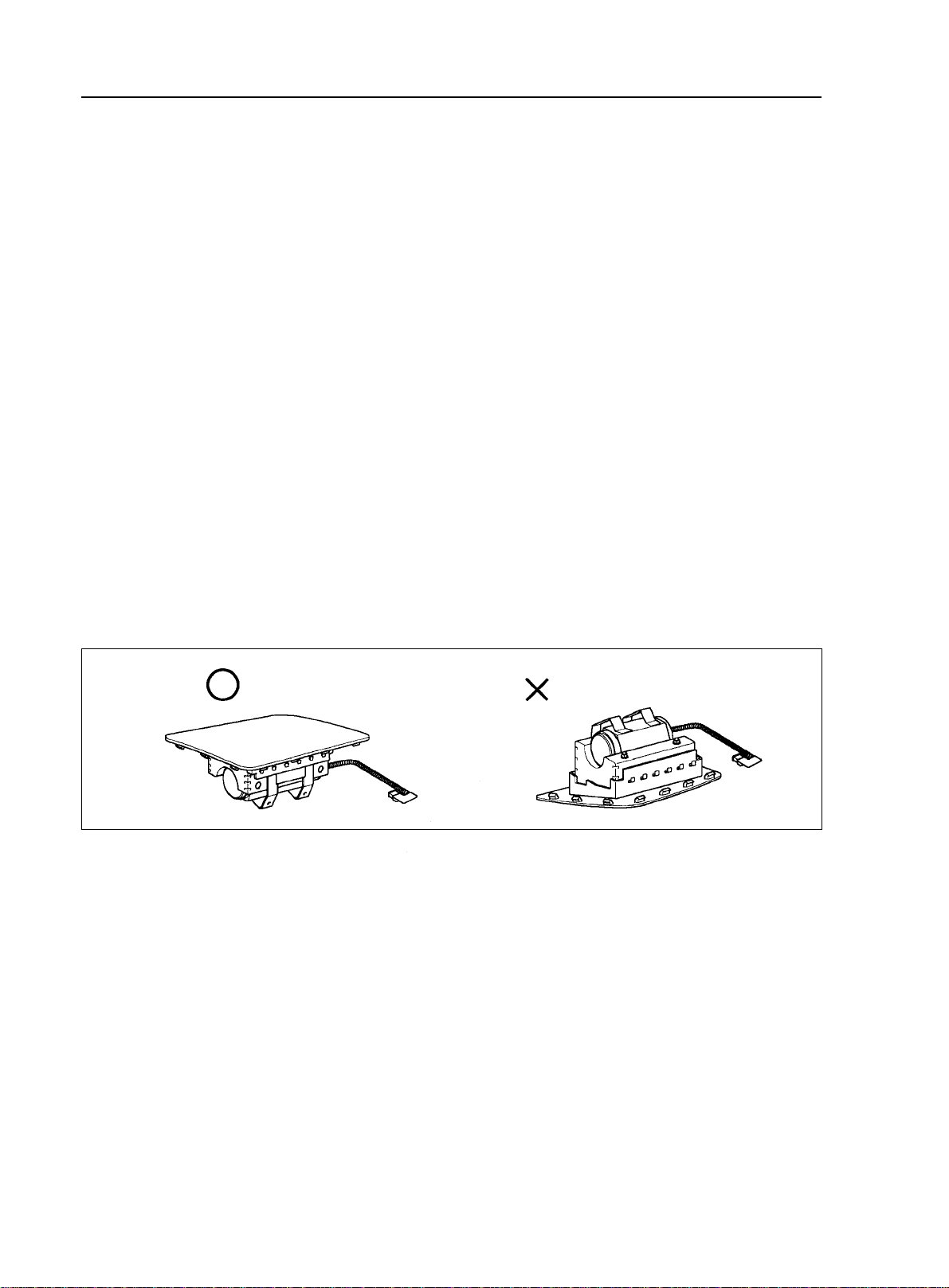
(4) Front Passenger Airbag Assembly
a. Always store a removed or new front passenger airbag assembly with the airbag rupture surface facing
up. Storing the airbag assembly with the airbag rupture surface facing down could cause a serious accident if the
airbag inflates.
b. Never measure the resistance of the airbag squib. (This may cause the airbag to deploy, which is very
dangerous.)
c. Grease should not be applied to the front passenger airbag assembly and the airbag door should not be
cleaned with detergents of any kind.
d. Store the airbag assembly where the ambient temperature remains below 93°C , without high humidity
and away from electrical noise.
e. When using electric welding, first disconnect the airbag connector (yellow color and 2 pins) installed on
the assembly before starting work.
f. When disposing of a vehicle or the airbag assembly alone, the airbag should be deployed using an SST
before disposal. Perform the operation in a safe place away from electrical noise.
Correct
Wrong
General Information - Repair Instruction
1-9
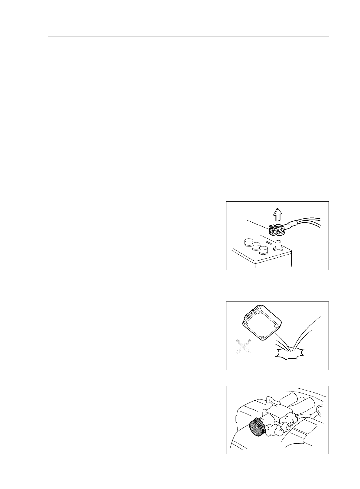
3. Electronic Control Device
(1) Removal of the battery terminal cable
a. Before performing electrical servicing, disconnect the nega-
tive (-) cable from the battery in order to avoid short for burnout.
b. When disconnecting the terminal cable, turn of f the ignition
and light switches, loosen the cable nut and raise the cable straight
up without twisting or prying it.
c. When disconnecting the terminal cable from the battery, all
information stored in the clock, radio and DTC shall be deleted,
therefore, these information shall be checked before disconnection.
(2) Processing of Electronic Parts
a. Do not open the cover or case of the ECU unless absolutely
necessary. (If the IC terminals are touched, the IC may be destroyed
by static electricity.)
b. To pull apart electrical connectors, pull on the connector itself,
not the wires.
c. Be careful not to drop electrical components, such as ECU
or relays. If they are dropped on a hard floor, they should be replaced
and not reused.
d. When steam cleaning an engine, protect the electronic
components, air filter and emission-related components from water.
e. Never use an impact wrench to remove or install tempera-
ture switches or temperature sensors.
f. When checking continuity at the wire connector, insert the
tester probe carefully to prevent terminals from bending.
4. Remove and Installation of Engine Intake Parts
(1) If any metal scrap is mixed in the inlet pass, that may give
a bad effect to the engine.
(2) When removing and installing of the inlet system parts, close
(6) Airbag ECU
a. Never reuse the airbag ECU involved in a collision when the SRS has deployed.
b. The connectors to the airbag sensor assembly should be connected or disconnected with the airbag ECU
mounted on the floor. If the connectors are connected or disconnected while the airbag ECU is not mounted to
the floor, it could cause undesired inflation of the supplemental restraint system.
c. Work must be started after 60 seconds from the time the ignition switch is turned to the "LOCK" position
and the negative (-) terminal cable is disconnected from the battery, even if only loosing the set bolts of the
airbag ECU.
(7) Wire Harness and Connector
The SRS wire harness is integrated with the instrument panel wire harness assembly. All the connectors in
the system are a standard yellow color. If the SRS wire harness becomes disconnected or the connector becomes
broken due to an accident, etc., repair or replace it.
Negative(-)
Cable
Wrong
General Information - Repair Instruction
1-10
3.Precautions for Use of Jack and Safety Stand
(1)always use the wheel stoppers when performing servicing on
level ground.
(2)use safety stand and rubber support as shown in the illustration.
(3)use the jack and safety stand to support specified location.
(4)When jacking up the front wheels of the vehicle, release the
park brake and place stoppers only behind the rear wheels. When
jacking up the rear wheels, place stoppers only before the front wheels.
(5)During the job, make sure to use safety stand instead of jack
only to support the vehicle.
(6)When only jacking up the front wheels or rear wheels, place
stoppers before or after the wheels touching the ground.
(7)when lowering the vehicle with its front wheels lifted, release
the park brake, and place the stopper only before the rear wheels.
When lowering the vehicle with its rear wheels lifted, place the stop-
per only after the front wheels.
the opening of the removed inlet system parts and the engine with a
clean shop lag or gum tape.
(3)When installing the inlet system parts, check that there is no
mixing of a metal scrap.
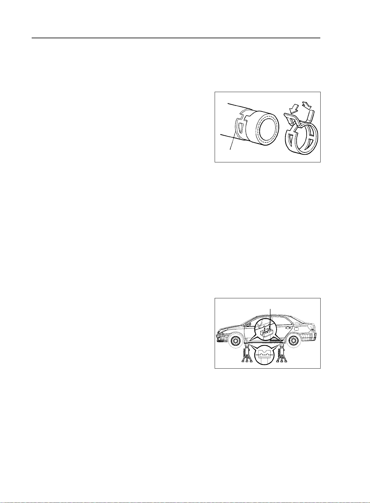
5. Handling of Hose Clamp
(1)Before removing the hose, check the clamp position to re-tighten
it for sure.
(2)Replace a deformed or dented clamp with a new one.
(3)In case of reusing the hose, install the clamp on the hose where
it has a clamp track.
(4)For a steel band circlip, make it adjust by adding force to the
arrow mark direction after the installation.
II. Vehicle Lift and Support Location
1. Vehicle Conditions To Be Under Attention During Lift
(1)Generally speaking, when being lifted, the vehicle should be empty, do not lift the heavily loaded vehicles.
(2)When removing heavy parts such as engine and transmission, the center of gravity of the vehicle will move.
Place balance weight to prevent the vehicle from rolling or use special jack to support the vehicle.
2. Precautions for Use of Four-tappet Lift
(1)follow the safe operation instruction described in this manual.
(2)do not damage the tire or rim.
(3)use wheel stopper to retain the vehicle.
Rubber Suport
Steel Band Circlip
Clamp Trace
General Information - Repair Instruction
1-11
4. Precautions for Use of Swing Arm Type Lift
(1) follow the safe operation instruction described in this manual.
(2) use bracket with rubber support as shown in the illustration.
(3) make the center of gravity of the vehicle as close as possible to that of the lift ("L" should be smaller).
(4) adjust the bracker height, level the vehicle, align the groove of the bracket with the safety stand
support location.
(5) the arm should be locked during the job
(6) lift the vehicle until the tires become round.Swing the vehicle to make sure of stable vehicle.
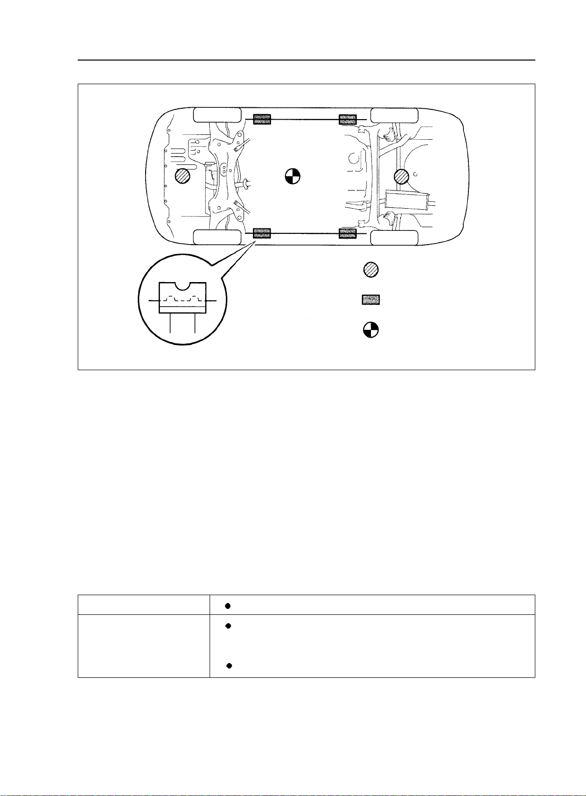
5. Precautions for Use of Plate Type Lift
(1) follow the safe operation instruction described in this manual.
(2) use the support of the plate type lift.
(3) make sure to secure the vehicle in the specified position.
Left and right set position
Front and rear set position
•
Place the vehicle over the center of the lift.
•
Align the cushion gum ends of the plate with the attachment
lower ends (A, C).
•
Align the attachment upper end (B) with the front jack supporting point.
Support Position
Jack Lifting Position
Jack Position
Center of Gravity of the Vehicle
(empty load)

Swing Arm Type Lifter
Lift Center
Plate T ype Lift
General Information - Repair Instruction
1-12
(3)lift the vehicle until the tires become a little bit round. Swing the vehicle to make sure of stable vehicle.
Cener of Gravity of the Vehicle
(Empty Load)
rubber support
Support Dimension
Support
Part II Vehicle Usage and Maintenance
Chapter 1 Brief Introduction of Geely MK
Section 1 Major Functional and Technical Data of MK Series.
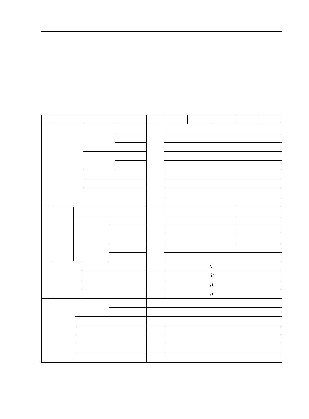
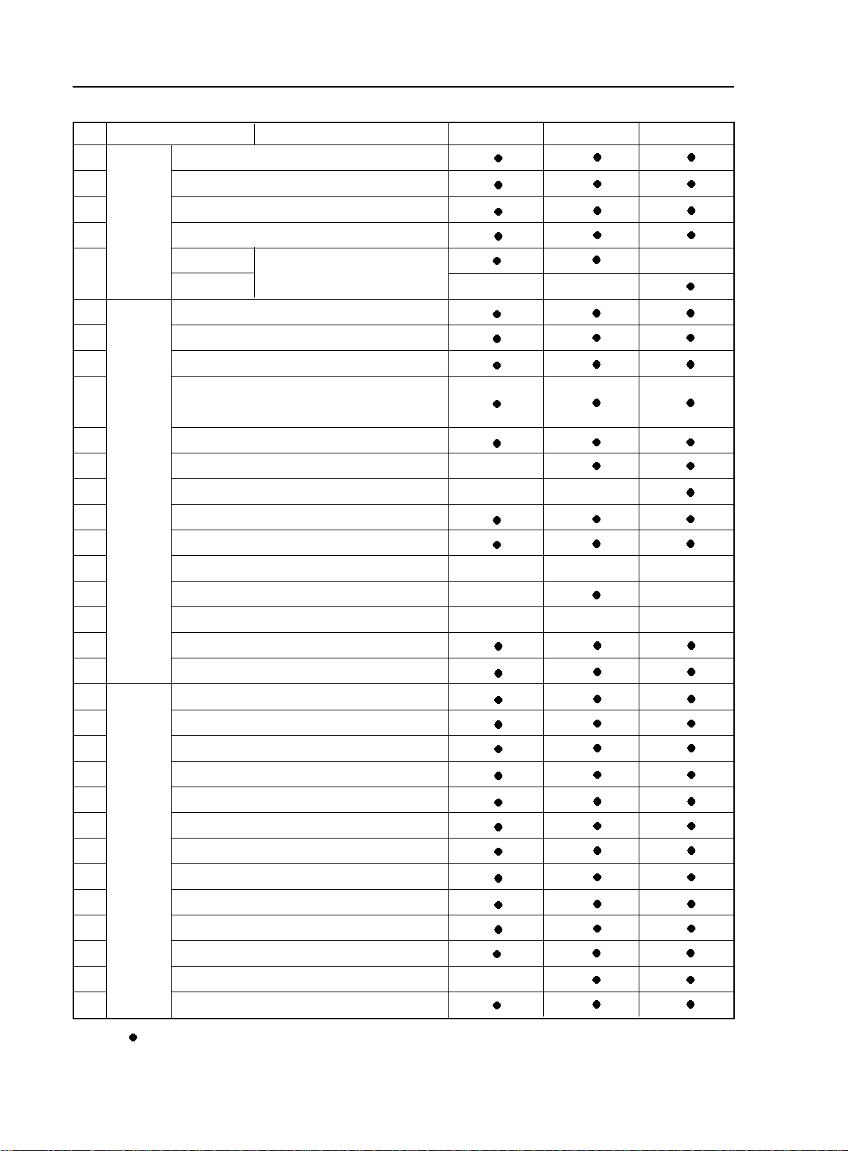
I. Vehicle performance and structural data
Table 1 vehicle data
Vehicle Usage and Maintenance - Brief Introduction of Geely MK
2-1
JL7162U
JL7152U
JL7132U
Unit
mm
mm
person
kg
m
mm
°
mm
Item
ID
1
2
3
4
5
Dimension
Dimension
Axle
4342
1692
1435
1450
1431
2502
848
992
5
150mm
15°
20°
-0°30'±45'
1±2mm
Length
Width
Height
Front
Rear
Wheelbase
Front Suspension
Rear suspension
Number of passengers
Weight
Curb weight
Front Axle
Rear Axle
V ehicle
Front
Rear
Curb
Gross Vehicle
W eight
Road
adaptability
Minimum turning diameter
Minimum Ground Clearance
Approach angle
Deviation angle
Wheel
Posi-
tioning
Left: Inner/out
Right: inner/out
Max turning angle
of front wheel
Front wheel leaning angle
Kingpin inward leaning angle
Kingpin rearward leaning angle
Left front wheel toe-in
Rear wheel outward
JL7132HU JL7152HU
1090(1040)
660(640)
430(400)
1460(1410)
780(760)
680(650)
1080
665
415
1450(1455)
780(785)
670
10.4m
°
°
°
°
°
°
°
37.2°±2°/ 32°±2°
37.2°±2°/ 32°±2°
2°0'±45'
10°0'±45'
-0°56'±45'
II. Introduction of major systems
Table 2 Models and technical data of major systems.
JL7132U JL7152U JL7162U JL7132HU JL7152HU
4
MR479Q MR479QA MR481QA MR479Q MR479QA
In-line 4 cylinderIn-line 4 cylinder In-line 4 cylinder In-line 4 cylinder In-line 4 cylinder
78.7 78.7 81.0 78.7 78.7
69.0 77.0 77.0 69.0 77.0
1.342 1.498 1.587 1.342 1.498
9.3 : 1 9.8 : 1 9.6 : 1 9.3 : 1 9.8 : 1
63/6000 69/6000 78.7/6000 63/6000 69/6000
110/5200 128/3400 137/4400 110/5200 128/3400
800±50
1-3-4-2 1-3-4-2 1-3-4-2 1-3-4-2 1-3-4-2
259 279 269 259 279
JL-S160 JL-S160A JL-Z110 JL-Z130
3.182 3.087 3.087
1.895 1.634 1.634
1.250 1 1
0.909 / /
0.703 / /
3.083 2.29 2.29
4.308 3.317 3.317
Hydraulic Gear-rack
Hydraulic, X-type pipe
Vacuum booster, Front Wheel Disc, Rear Wheel Drum
McPherson suspension strut system
Twist beam independent suspension system
85/60R15(1175/65R14)
230(Front)/210(Rear)
Aluminum 15X6J (Iron 14X5 1/2JJ)
45
Unitary construction body
Unit
mm
mm
L
kw/r/min
N
.
m/r/min
r/min
g/kw
.
h
KPa
L
Item Description
Drive Type
ID
1
2
3
4
5
6
7
8
9
10
Engine
Model
Type
Bore Diameter
Piston play
Displacement
Compression Ratio
Max Power
Max Torque
Idle Speed
Ignition Sequence
minimum fuel consumption rate
Transmission
Braking
system
suspension
Tire
Clutch Type
Steering type
Model
Booster type
Front
Rear
Specification
Tire pressure
Wheel
Fuel Tank Capacity
Body structure
Single disc, Plate and dry Spring
Brief Introduction of Geely MK - Major Functional and Technical Data of MK Series.
2-2
Model
1st gear
2nd gear
3rd gear
4th gear
5th gear
Reverse gear
Final Drive Ratio
/
Front Wheel Drive
›‹
2
800±50 800±50
800±50
800±50
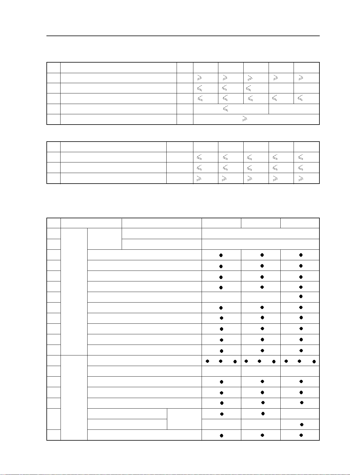
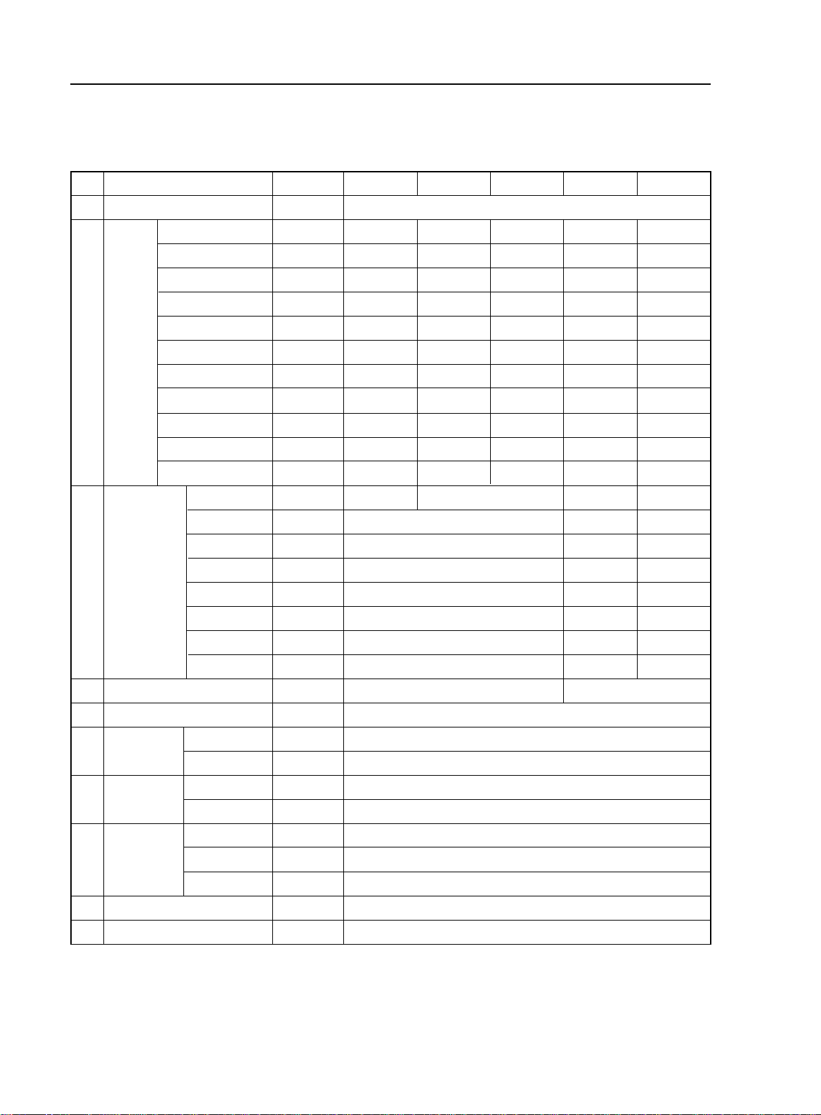
Table 3 Power Performance Parameter
Table 4 Economic Performance Parameter
Unit
km/h
s
s
km/h
%
Item Name
Maximum vehicle speed
Acceleration time within the fourth gear from 30km/h to 120km/h
Acceleration time from 0-100km/h
Minimum stable vehicle speed within the fourth gear
Maximum gradeability
No.
1
2
3
4
5
Unit
L/100km
L/100km
m
Item Name
Fuel consumption at constant speed (60km/h)
Fuel consumption at constant speed (90km/h)
Coasting distance (fully loaded, initial speed 50km/h)
No.
1
2
3
JL7132U JL7152U JL7162U JL7132HU JL7152HU
/
JL7132U JL7152U JL7162U
JL7132HU JL7152HU
4.5
550
Brief Introduction of Geely MK - Vehicle Configuration
2-3
Section 2 Vehicle Configuration
Type
Common color
Uncommon color
Exterior
device
Seat
Interior
device
Item Name
No.
1
2
3
4
5
6
7
8
9
10
11
12
13
14
15
16
17
18
19
Standard Comfortable Luxury
Firry red Firry red
Titanium silver
Body color
Chinese red, snow mountain white, pearl black, sky blue, ribbon silver
Crystal diamond silver, golden sand green, pineapple yellow
Front chromeplated trim molding
Diamond-shape headlight
Crystal diamond taillight
Highly penetrable front fog light
Green heat insulating four-door glass
Scuff strip with same color as that of the body
Aluminum alloy wheel rim
Tire (185/60R15) (with spare tire)
Retractive antenna (A pillar)
Bumper with same color as that of the body
Light color (T)deep color(S)mixed color(R)interior trim
Central control panel
A/C outlet vent + trim ring
Chromeplated inner handle
Sun shade (with ticket folder)
High-grade flannelette
Luxury leather
Front seat headrest front and rear angle/height adjustable function
//
20
25
22
16.5
18
20
165
33
28
30
155175165155
30
6.2
5.1
4.6 5.0
4.7
6.7
6.3
6.66.2
550
550
550
550
/ /
/ / / /
Brief Introduction of Geely MK - Vehicle Configuration
2-4
Electric
device
Interior
device
Adjustable steering wheel
Remark: - denote standard configuration Z - standard C - comfortable D - luxury S - dark interior trim
T - light colored interior trim R - mixed color
Type
Item Name
No.
20
21
22
23
24
25
26
27
28
29
30
31
32
33
34
35
36
37
38
39
40
41
42
43
44
45
46
47
48
49
50
51
Standard Comfortable Luxury
Single Disc Single Disc 6 Discs
6 speakers (2 Tweeters) 6 speakers (2 Tweeters) 6 speakers (2 Tweeters)
Front seat back trash bag
6/4 split foldable rear seat
Cable-controlled oil tank cap
Cable-controlled trunk
plastic
leather
Power window (with one-touch function)
Remote control central door lock
Power rearview mirror with turn signal light
Smart remote control key (control the closure of the
door and window and the delay of the vehicle lights)
Adjustable intermittent wiper
On-board handsfree handset
Anti-clamp retractive power window
Central pointer type instrument
Temperature display
Hi-fi CD audio
MP3 function
Speaker
Freon-free A/C system
Air cleaner
ABS + EBD
Driver side airbag
Front passenger side airbag
Telescopic steering column
Front seat belt pretensioner /height adjustable
Rear row triple-person seat belt
Anti-glaze inner rearview mirror
Anti-explosion and anti-leak plastic oil tank
Rear windshield defroster function
High-mounted stop light
Four-door anti-impact beam
Digital display rear parking radar
Follow me home light delay system
Safety
device

Section 3 Main Vehicle Test Technical Specification
Description
Front wheel outward leaning angle
Kingpin inward leaning angle
Kingpin rearward leaning angle
Left front wheel toe-in (mm)
Rear wheel outward leaning angle
% of braking total power vs. gross vehicle weight
% of front wheel braking power vs. front axle load
% of gap between left and right wheel brake power vs. the
greater braking power of them two
rolling resistance of each wheel should not be larger than the axle load by
parking brake total power should be lighter than the test vehicle weight by
sliding distance of front/rear wheels
when vehicle speed meter shows 40km/h, vehicle speed
monitor indicates
brightness of left/right headlamps
tolerance of close lamps is
tolerance of distant lamps is
Harsh brake at 50km/h. the stop distance is
Rain test. 100 points is full mark. Minus one point for each
seepage. Minus 3 points for slow seepage 3 points, and minus
6 for a quick seepage. The limit of vehicle sealing is
Check leaks of the vehicle. When vehicle has run 50km, stop it and
inspect for leaks. Check if there is oil/water marks at static joints,
or if there is oil/water drops dripping down at dynamic joints
10min after the vehicle is stopped, there is a leak; if there is oil/
water marks/drops, but it does not drip down, there is seepage.
Measure the temperature of transmission oil inspection hole.
Usually it is not higher than ambient temperature.
Check the surface temperature of wheel trim column. Usually
it is no higher than ambient temperature.
vehicle should be slightly steering insufficient i.e. driving on
a circle with same steering wheel angle, and accelerate from
low to high speed, the diameter of the circle increases gradually.
Maximum front wheel turning angle (inner/outer)
Item
Specification: GB18352.3-2005
Brief Introduction of Geely MK - Main Vehicle Test Technical Specification
2-5
Inspection
line items
Regular
quality
inspection
items
Specification
-0°30'± 45'
10°0'± 45'
2°0'± 45'
1±2
-0°56'± 45'
60% (no load, and full load)
20%(Front Axis),
24%(Rear Axis)
5%
20%
2 m/km
33.3 Km/h-42.1Km/h
15000 cd
(0.6-0.8)H, H refers to the central
height of headlamps.
10cm/10m
19m
93 points
Daily inspection and smell with
nose
70°C
40°C
Inspect regularly
37.2°±2°/ 32°±2°
Emission
60% (no load),
50% (full load)

Chapter 2 Usage and Maintenance of MK Series
Section 1 Usage of MK Series
1. Instrument Panel Overview
1.Instrument Panel Outlet Vent
2. Instrument Panel
3.Upper Glove Compartment
(Front Passenger Airbag Cover)
4.Sunshade
5.Dome Light And Sunroof
Switch
6.Inside Rearview Mirror
7.Glove Box
8. Power Window Regulator
Switch
9. Manual Transmission Shift
Lever Or Automatic Transmis-
sion Shift Lever
10.Parking Brake Control Lever
11.Engine Hood Release Handle
12.Power Window Lock
13.Power Door Lock Switch
1.Left Combination Switch
2.Right Combination Switch
3.Display
4.Audio
5.Short-Distance Odometer
Adjustment Button
6.Instrument Panel Brightness
Adjustment Switch
7.Hazard Warning Light
8.A/C Control Panel
9.Ash Tray
10.Defroster Switch
11.Cigarette Lighter
12.”A/C“ Switch
13.Ignition Switch
14.Tilt Steering Adjustment
Handle
15.Theft-Deterrent Indicator
16.Power Outside Rearview
Mirror Control Switch
Usage and Maintenance of MK Series - Usage of MK Series
2-6
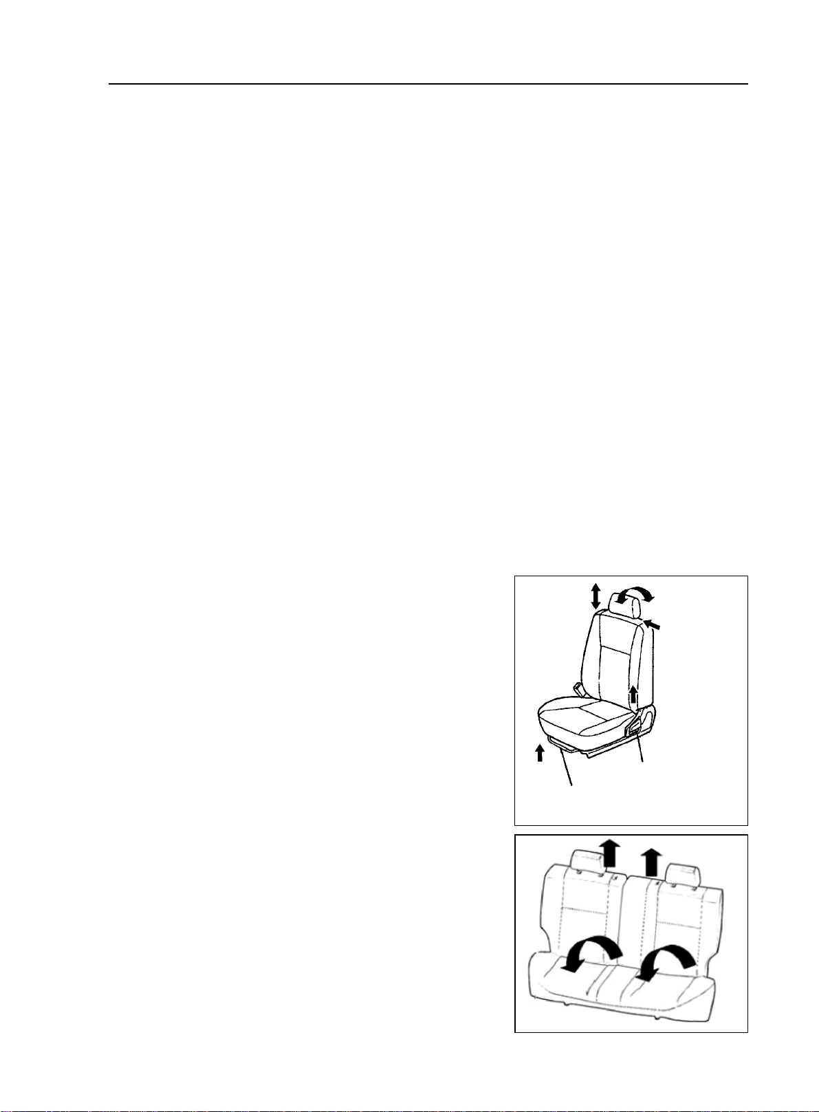
Adjust seat back angle
Move seat forward or backward angle
Usage and Maintenance of MK Series - Usage of MK Series
2-7
2
1
2.How to use ignition switch
(1) LOCK when key is at this position, it can be pulled out and inserted in easily. The function of this position
is to lock steering wheel. If the key cannot be turned from LOCK to ACC, please rotate the steering wheel slightly
while turning the ignition key.
(2) ACC radio and cigarette lighter is turned on when key is at this position.
(3) ON when key is at this position, the following indicator is on: battery charging, ABS, brake fluid level,
park brake, engine coolant temperature, engine MIL, airbag oil pressure.
(4) START Turn the key to this position to start the engine. When engine is started, release the key
immediately. It returns to ON automatically. When engine is on, do not turn the key to this position.
Notice:
(1) Do not pull the key out or turn it to LOCK before the car is fully stopped, or there will be dangers caused
by locking steering wheel or disabling some safety functions.
(2) It is prohibited to drive the car with engine turned off to ensure functioning of braking and steering booster.
(3) Do not let the key stay at ON for a long time when engine is off, or the battery fully discharged.
(4) Shift to neutral gear before ignition key is switched to START.
(5) Turn the steering wheel lightly after the car is fully stopped to make sure it is locked.
3.Unlock Steering Wheel
How to unlock steering wheel: insert ignition key, turn the steering wheel lightly and switch the ignition key.
Steering wheel is unlocked.
4.Adjust seat position
Seat back angle and cushion angle of front seats in MK-1 sedan can be adjusted.
(1) Adjust seat back angle
Turn around adjusting handle, and adjust seat back to appro
priate position.
(2) Move seat forward or backward
Steps:
a. pull adjusting handler up
b. Move the seat forward or backward, and adjust the seat to
appropriate position.
c. Put the handler down and move the seat again till it is
locked.
Attention: adjust the seat only when the car is fully stopped
to ensure safety.
(3) Front head rest can be adjusted in two ways.
Push the head rest from back to front, there are three fixed
positions to lock.If pushed over the final locking position,the
head rest can return to the original position after hand
withdraws.
(4) Fold Rear Row Seat
The seat back can be tilted forward so that the trunk will be
used to the last degree.
a. Remove the head rest
b. Unlock the seatback and fold it down.
Split seatback can be folded separately on demand.

2-8
5. Actions to ensure vehicle working condition and safe driving.
(1) To make sure of driving safety, execute the following inspections before driving.
a. Inspect fuel level, and add fuel when necessary.
b. Inspect illuminating lights, turning signal lights, braking signal lights to see if they work.
c.Check the position of rearview mirrors.
d.Check if breaking system functions well.
e.Check if glass of all the lights, windshield is clean.
(2) Regular inspection Perform the following regular inspections to ensure the vehicle work condition and
driving safety.
a. Check engine oil level. Park the vehicle on flat road; check the oil level with engine oil level indicator
at least 10 minutes after the engine is stopped. The oil level should be between the two marks. If it is
lower than "L" mark, add some oil; if it is higher than "F" mark, there is excessive oil, so release it.
Or investigate the cause of high oil level.
The volume between the lowest oil level ("L") and highest oil level ("F") is 1.4L.
b. Check engine coolant level. Check the level when the engine is cool. The coolant level should be between
LOW and FULL. If it is lower than "LOW", add coolant. If the coolant is much lower than Min (every
coolant fill is more than 1L) or the vehicle requires frequent fills,investigate if there is any problem with
the cooling system.
To keep the function of coolant, replace coolant every two years at the beginning of cold winter.
c. Check brake and clutch fluid level (sharing a reservoir). Brake fluid level should between the Max and
Min marks. And it is better to keep it close to the Max mark. Add fluid in time when there is not enough
fluid.
d. Check power steering fluid tank. The level should be between Max and Min marks. Refill when there
is not enough steering fluid to avoid pump stuck. It is strictly prohibited to run the vehicle without
steering fluid in any circumstances.
e. Check the charging status of battery and if the connection of battery wires is good.
f. Check tire status and pressure
g. Check the status of wipers.
(3) Observe warning lights and indicators on instrument panel.
a. There are various warning lights and indicators on the instrument panel of MK-1 sedans to indicate and
warn abnormal operations of engine, braking, and charging systems.
b. Pay attention to these lights when driving.When the warning lights or indicators are on,stop the vehicle,
check the vehicle and resolve the causes to make sure the vehicle works well or drives safely.
6. Correct ways to use new cars
Reliability and stability of components in new cars and recently repaired cars still need to be confirmed, and
relative parts are not broken-in, so they must be used carefully to ensure driving safety, to avoid abnormal damage,
and to extend the useful life of the car.
(1) Before driving inspection The following inspections must be performed on the new car to ensure car safety
and reliable operation:
a. Check if instrument panel, warning lights, and indicator, front and rear wiper and washer, and switches
work.
b. Check if the fastening of driveline, steering, suspension, wheels and other connection parts is good.
Usage and Maintenance of MK Series - Usage of MK Series

2-9
c. Check levels of braking fluid, engine coolant, engine oil, transmission oil, power steering fluid, and
washing fluid to see if there is any leaking.
d. Inspect if brake pedal, clutch pedal, accelerator pedal, transmission shifter, steering wheel, choke are
loose or stuck. The free travel of clutch pedal is 5~15mm, the free travel of brake pedal is 1~6mm and
the free play of steering wheel is less than 30mm(measurement point at margin of steering wheel). if it
is out of this normal range, the clutch needs to be tuned.
e. Inspect if the connection of battery, lamps and signal lights are normal, and if the wire routing and
position are correct and not loose.
f. Inspect if the tire pressure is correct.
(2) On-road inspection If the inspection result of the above items is good, start the engine and test the car on
road, and perform the following inspections.
a. Acceleration pedal, see if the operation is smooth and if it is loose.
b. Clutch, see if there is any stuck or abnormal noise, and slip when driving.
c. Transmission,check if shifting is smooth,or rough and wrong shifting.Inspect if the display of A/T
shift lever is normal.
d. Steering, check if steering is light and smooth, and if the steering wheel turns back after steering.
e. Brake pedal, apply brake pedal to check if the braking functions well when vehicle speed is at
40km/h and if the vehicle runs off track.
f. Park brake, when parking brake handler is pulled, there should be 6~9 clicking sounds. Pull park brake
when vehicle is running at the speed of 20km/h and transmission is at neutral gear to see if it brakes.
g. Vehicle speed meter, observe the vehicle speed meter while driving. When speed changes, check if the
indicator is moving steadily or shakes.
h. Heating and air-conditioning.Try every control button to see if both heating and cooling system work
well.
i. Abnormal noise, listen carefully to see if there is any abnormal noise from engine, drive line system or
any other parts of the vehicle at a steady speed and during accelerating, and decelerating.
(3) Inspection after test ride check if there is anything abnormal in the vehicle while driving and conduct the
following inspections after the vehicle is parked.
a. Check electrical fan When engine coolant temperature is beyond 92.5°C, the radiator fan should be
running; When A/C is on and the pressure of refrigerant is more than 1.5 cooling ton, air conditioning
cooling fan should be running.
b. Check headlamp, method: park the car 5m away from the inspection surface (inspection board, curtain,
or wall) to the front bumper, and check if the beam from headlamp is good. The upper level if headlamp
should be 540mm above the ground, and the distance between headlamps on the two sides is 900mm.
c. Inspect engine idle speed,idle speed of hot engine is 800r/min±50r/min,when A/C compressor works,
the idle speed should be 900r/min±50r/min. If idle speed is abnormal, adjust the idle speed adjust
ment screw to adjust it.
(4) Usage of new cars in breaking-in period Follow the instructions below in the first 1500~2500km breaking
mileage to avoid wear and abnormal damage in breaking-in period, and to improve vehicle performance, fuel
economy and to extend vehicle useful life.
a. Drive steadily during breaking-in; do not accelerate harshly to avoid running engine at high speed.
Engine should not exceed 4500r/min in any gears. Especially at the early stage of breaking-in, vehicle
Usage and Maintenance of MK Series - Usage of MK Series
 Loading...