

Page 1

Page 2

Page 3

Foreword
Geely “MK” series sedans (JL7132U,JL7132HU,JL7152U,JL7152HU,JL7162U) are brand
new superior models developed by Geely Group who has fully proprietary intellectual property
rights. As a result of the three years of involvements and ef forts of the experts from Geely Automobile Research Institute, these sedans reach international leading level in model design, power,
sense of comfort, safety and manufacturing technology while featured in beautiful appearance,
economy , environment protection and safety. The meaning of MK implied that Geely Automobile
has a great development from caterpillar to butterfly . W ith respect to the power, Geely “MK” series
sedans are equipped with 1.3L, 1.5L, and 1.6L EFI engines developed and manufactured by Geely
itself, and has reached “Chinese III” (Euro III) emission standard.
This manual contains a detailed description of the structures and principles, servicing and adjustment,
removal, assembling technology and matching clearance of the parts of the Geely “MK” sedans
with torque information of the bolts and nuts as well as schematic diagram for special tool operation.
This manual also introduces the transmission control system of the automatic transmission models,
vehicle electric circuits and elaborates ABS system, SRS, BOSCH M7.9.7 electronic control fuel
injection and ignition system, rear parking radar, sound, air conditioning and onboard hands-free
phone system. You can refer to this manual for the information about the regular maintenance,
servicing, adjustment, troubleshooting, removal and installation procedure, specific operations of
the “MK” sedans.
This manual covers the matching relation among the engine assembly, transmission assembly and
the vehicle, but does not have the further description of the structures and principles of the engine
and transmission assemblies and their servicing process. You can refer to the service manuals
solely prepared for engine assembly and transmission assembly for these information.
All information in this manual is based on the latest products released at the time of publication of
this manual. However, the specifications and procedures may need to be modified, and the subsequent change will be revealed in later versions.
This manual is prepared by Geely Automobile Research Institute under the assistance of technical
staff from Zhejiang Geely Automobile Co., Ltd and Geely International Corporation. Readers
discovering during the use of this manual the errors and careless omissions due to limited skills of
the preparers and tight schedule are encouraged and pled to contact Geely International in time for
our timely correction of the mistakes.
Geely International Corporation
Nov . 2007
Page 4

Table of Contents
Table of Contents
Part I General Information
Chapter 1 How to Use This Manual .................................................................................. 1-1
Chapter 2 Repair Instruction ............................................................................................. 1-3
Part II V ehicle Usage and Maintenance
Chapter 1 Brief Introduction of Geely MK ......................................................................... 2-1
Section 1 Major Functional and Technical Data of MK Series. ...................................... 2-1
Section 2 Vehicle System Configuration........................................................................ 2-3
I
Section 3 Main Vehicle Test Technical Specification...................................................... 2-5
Chapter 2 Usage and Maintenance of MK Series ............................................................ 2-6
Section 1 Usage of MK Series ....................................................................................... 2-6
Section 2 Maintenance Category and Content of MK Sedan..........................................2-12
Section 3 Daily Maintenance of MK Sedan.................................................................... 2-18
Part III Engine
Chapter 1 Engine Assembly ............................................................................................... 3-1
Section 1 Engine Inspection........................................................................................... 3-1
Section 2 Removal of the Engine Assembly from the Vehicle ....................................... 3- 5
Section 3 Drive Belt Replacement.................................................................................. 3 - 7
Chapter 2 Engine Mechanical ............................................................................................ 3-8
Section 1 Engine Components....................................................................................... 3-8
Section 2 Throttle Body .................................................................................................. 3-12
Section 3 Valve Clearance Adjustment .......................................................................... 3-14
Chapter 3 Fuel System ....................................................................................................... 3-15
Section 1 Check Fuel System Pressure......................................................................... 3-15
Section 2 Fuel Pump Inspection..................................................................................... 3-16
Section 3 Fuel Pump Replacement................................................................................ 3-17
Page 5

II
Section 4 Fuel Emission Control System ....................................................................... 3-18
Section 5 Carbon Canister Replacement....................................................................... 3-19
Chapter 4 Exhaust System ................................................................................................. 3-21
Chapter 5 Cooling System ................................................................................................. 3-22
Section 1 System Inspection .......................................................................................... 3-22
Section 2 Radiator Replacement................................................................................... 3-24
Chapter 6 Manual Transaxle Assembly ............................................................................. 3-25
Section 1 Frequent Problem Diagnosis.......................................................................... 3-25
Section 2 Vehicle Speed Sensor Replacement ............................................................. 3-26
Section 3 Manual Transaxle Replacement..................................................................... 3-27
Section 4 Transmission/Transaxle Case Oil Seal Replacement .................................... 3-28
Chapter 7 Automatic Transaxle Assembly ........................................................................ 3-29
Table of Contents
Section 1 Frequent Problems Diagnosis........................................................................ 3-29
Section 2 Hydraulic Torque Converter and Transaxle.................................................... 3-30
Section 3 Differential Front Oil Seal (ATM) .................................................................... 3-33
Section 4 Neutral Switch Assembly................................................................................ 3-35
Part IV Chassis
Chapter 1 Transmission Control ........................................................................................ 4-1
Section 1 Introduction of Transmission Control ............................................................. 4-1
Section 2 Cable Type Transmission Control .................................................................. 4-3
Section 3 Manual Transmission Shift Mechanism.......................................................... 4-5
Section 4 Automatic Transmission Shift Mechanism...................................................... 4 -7
Chapter 2 Accelerator Pedal Device ................................................................................. 4-11
Section 1 Introduction of Accelerator Pedal................................................................... 4-11
Chapter 3 Clutch Control System ...................................................................................... 4-12
Section 1 Introduction of Clutch Centrol......................................................................... 4-12
Section 2 Clutch Pedal ................................................................................................... 4-13
Chapter 4 Propeller Shaft/Driveshaft ................................................................................ 4-17
Section 1 Propeller Shaft, Driveshaft and Transaxle ..................................................... 4-17
Page 6

Table of Contents
Section 2 Front Driveshaft.............................................................................................. 4-19
Section 3 Front Wheel Hub ............................................................................................ 4-30
Section 4 Rear Wheel Hub and Bearing Assembly ....................................................... 4-35
Chapter 5 Front Suspension System ................................................................................ 4-38
Section 1 Front Suspension System .............................................................................. 4-38
Section 2 Front Suspension ........................................................................................... 4-40
Section 3 Front Wheel Alignment................................................................................... 4-43
Section 4 Front Strut Assembly...................................................................................... 4-46
Section 5 Front Lower Swing Arm Assembly ................................................................. 4-49
Section 6 Front Stabilizer Bar and Link Rod Assembly.................................................. 4-53
Chapter 6 Rear Suspension System ................................................................................. 4-54
Section 1 Rear Suspension System............................................................................... 4-54
III
Section 2 Rear Wheel Alignment ................................................................................... 4-56
Section 3 LH/RH Rear Suspension Coil Spring ............................................................. 4-57
Section 4 Rear Absorber Installation Assembly ............................................................. 4-60
Section 5 Rear Suspension Crossmember .................................................................... 4-62
Chapter 7 Wheel .................................................................................................................. 4-66
Section 1 Tire Inspection and Wheel Replacement....................................................... 4-66
Chapter 8 Power Steering System .................................................................................... 4-67
Section 1 Power Steering System.................................................................................. 4-67
Section 2 Steering Drive and Control Mechanism ......................................................... 4-69
Section 3 Steering Pipeline Component ........................................................................ 4-73
Section 4 Power Steering Gear...................................................................................... 4-75
Chapter 9 Brake System .................................................................................................... 4-79
Section 1 Brake System ................................................................................................. 4-79
Section 2 Brake Fluid ..................................................................................................... 4-81
Section 3 Brake Pedal.................................................................................................... 4-82
Section 4 Brake Master Cylinder Assembly ................................................................... 4-85
Section 5 Vacuum Booster ............................................................................................. 4-91
Section 6 Front Brake Disc............................................................................................. 4-94
Page 7

IV
Section 7 Rear Brake Drum............................................................................................ 4-99
Section 8 Parking Brake System.......................................................................................4-106
Table of Contents
Part V Electric System & Accessory
Chapter 1 Starting and Charging System ......................................................................... 5-1
Section 1 Starting System (MR479Q, MR479QA, MR481QA) ...................................... 5-1
Section 2 Charging System (MR479Q, MR479QA, MR481QA) .................................... 5-3
Chapter 2 Combination Instrument System ..................................................................... 5-7
Section 1
Section 2 Malfunction Symptom Table and Troubleshooting......................................... 5-10
Chapter 3 Wiper and Washer System ............................................................................... 5-21
Section 1 Wiper and Washer System Inspection........................................................... 5-21
Section 2 Replacement and Adjustment........................................................................ 5-23
Chapter 4 Light System ...................................................................................................... 5-26
Section 1 Light System Introduction............................................................................... 5-26
Section 2 Light System Malfunction Inspection ............................................................. 5-28
Section 3 Headlamp Replacement................................................................................. 5-34
Section 4 Front Fog Lamp Replacement ...................................................................... 5-35
Section 5 Rear Combination Lamp Replacement.......................................................... 5-36
Section 6 High-mounted Stop light Replacement .......................................................... 5-36
Section 7 Front Reading Lamp Replacement ................................................................ 5-37
Section 8 Rear Reading Lamp Replacement................................................................. 5-37
Wiring diagram of Combination Instrument and Location of Multi-pin Plug-in Terminal
5-7
Section 9 License Plate Lamp Replacement ................................................................. 5-37
Chapter 5 Audio System ..................................................................................................... 5-38
Section 1 Audio System Description .............................................................................. 5-38
Section 2 Audio System Connector Terminal Layout ..................................................... 5-40
Section 3 Audio System Inspection................................................................................ 5-41
Section 4 Audio System Replacement........................................................................... 5-52
Chapter 6 SRS (Supplemental Restraint System) ............................................................ 5-54
Page 8

Table of Contents
Section 1 SRS General Information ............................................................................... 5-54
Chapter 7 Air Conditioning System ................................................................................... 5-72
Section 1 General Information........................................................................................ 5-72
Section 2 Refrigerant...................................................................................................... 5-77
Section 3 A/C Operating Mechanism ............................................................................. 5-83
Section 4 Heater, Ventilation and Air Conditioning ........................................................ 5-86
Section 5 Layont of Air Conditioning Hose..................................................................... 5-92
Section 6 Multi-wedge belt (Connecting Compressor and Crankshaft Pulley).............. 5-93
Section 7 Compressor Assembly.................................................................................... 5-94
Section 8 Condenser Fan and Condenser Assembly.................................................... 5-96
Chapter 8 MK-60 ABS System ........................................................................................... 5-99
Section 1 ABS Diagnosis................................................................................................ 5-99
V
Section 2 ABS System Check ...................................................................................... 5-103
Section 3 Removal and Installation.............................................................................. 5-138
Section 2 Power Door Lock Control System ................................................................ 5-142
Part 6 Interior & Exterior Trim and Accessory
Chapter 1 Front Seat Assembly ......................................................................................... 6-1
Chapter 2 Rear Row Seat Assembly ................................................................................. 6-3
Chapter 3 Front Seat Belt ................................................................................................... 6-5
Chapter 4 Rear Seat Belt .................................................................................................... 6- 9
Chapter 5 Dashboard, Middle Console and Instrument Panel ....................................... 6-11
Chapter 6 Windshield ......................................................................................................... 6-16
Chapter 7 Rear Window Glass (with Defrosting Heater Wire) ........................................ 6-20
Chapter 8 Side Inner Panel Trim ........................................................................................ 6-22
Chapter 9 Roof Trim ............................................................................................................ 6-25
Chapter 10 Front Door Interior Trim .................................................................................. 6-27
Chapter 11 Rear Door Interior Trim ................................................................................... 6-30
Chapter 12 Front Bumper ................................................................................................... 6-33
Chapter 13 Rear Bumper .................................................................................................... 6-35
Page 9

VI
Chapter 14 Outside Rearview Mirror ................................................................................. 6-37
Chapter 15 Door Protecting Stripe .................................................................................... 6-38
Chapter 16 Carpet and Insulator ....................................................................................... 6-39
Chapter 17 Moonroof Assembly (Optional) ...................................................................... 6-40
Chapter 18 Plug List ........................................................................................................... 6-42
Table of Contents
Part 7 Body
Chapter 1 Survey ................................................................................................................ 7-1
Section 1 Body Structure................................................................................................ 7-1
Chapter 2 Body Repair ....................................................................................................... 7-9
Section 1 Body Damage Forms and Requirements for Repair...................................... 7-9
Section 2 Typical Technique of Body Panel Repair ....................................................... 7-16
Section 3 Repair After Body Damage ............................................................................ 7-16
Section 4 Features and Composition of Automobile Body ............................................ 7-24
Section 5 Painting Techniques After Body Repair ......................................................... 7-35
Section 6 Service Data For for Body.............................................................................. 7-36
Attachment: Body Key Dimensions
Appendix: T orque Table of the Fasteners for Important Assembly
Page 10

General Information - How to Use This Manual
1-1
Part 1 General Information
Chapter 1 How to Use This Manual
I. Instruction
1. General Information
(1)This manual conform to the first part of GB/T1.1--2000 Standardization Guide: The structure and preparing rule of the standard.
(2)Generally, the repairing job can be divided into the following 3 procedures:
1. Diagnosis
2. Removal and installation, replacement, disassembly and inspection, adjustment
3. Final inspection
(3) The first procedure “Diagnosis” (the details refers to each section or chapter) and second procedure “Removal and installation, replacement, disassembly and inspection, adjustment” are scattered in the chapters and
sections, and this manual omits the third procedure “Final inspection”.
(4) This manual does not include the following basic operations which are imperative in real scenarios.
a.
operate the jack or lifter
b. clean the removed parts if necessary.
c. inspect the appearance
2. Preparation
SST (Special Service Tools) and SSM (Special Service Materials) may be required and correctly used based
on the repairing condition, make sure the job procedure is followed.
3. Repair Procedure
(1) The disassembly illustration is placed under the title.
(2) The illustration shows the disassembly of the parts to help you understand the assembly of the parts.
(3) Non-reusable parts need to be coated with grease, and the precoated parts and torque are specially shown
in the disassembly illustration.
(4) Sometimes, the illustrations of the similar model are used where there may be some details differently
from the actual vehicle.
(5)The operational procedure is described in the following ways:
a. The illustration shows what to do and where to do it.
b. The task heading tells what to do.
c. The detailed text tells how to perform the task and gives other information such as specifications and
warnings.
4. Specification
Specifications are presented in bold type throughout the manual.
5.Term Definition
Caution indicates there is a possibility of injury to you or other people.
Notice indicates the possibility of damage to the components being repaired.
Tip provides additional information to help you perform the repair efficiently.
6. International System of Unit
The Units given in this manual are primarily expressed according to the International System of Unit.
Page 11
1-2
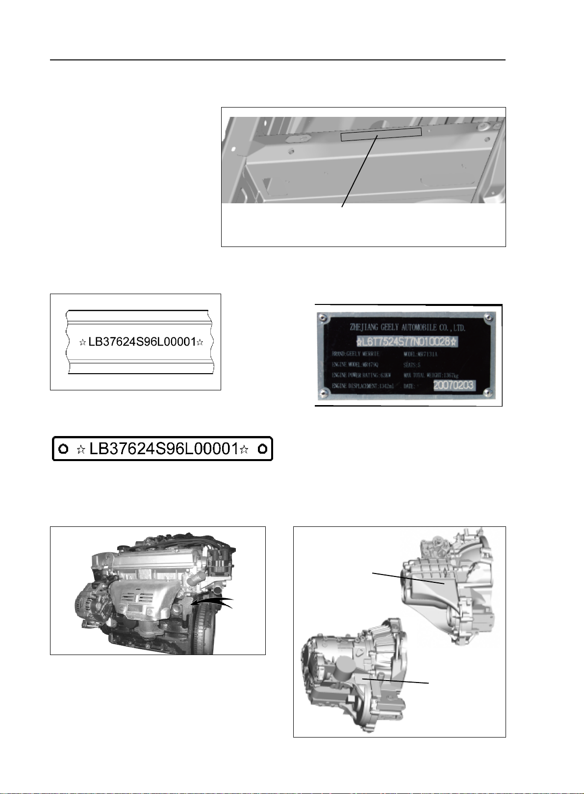
II. Vehicle Identification
1. Vehicle Identification Number
(VIN):
Vehicle Identification Number
(VIN) is the legal identification of the
vehicle which is printed on the middle
of the engine compartment cowl (as
shown in the illustration).
General Information - How to Use This Manual
VIN code position
2. VIN Code
4. VIN Code: on the left lower corner of the front windshield.
5. Engine Number:
marked on the engine block as shown in the illustration
3. Ex-work Nameplate: on the middle of the engine
compartment cowl
6. Transmission Mark:
printed on the left side of the transmission
Mark position
Mark position
Page 12
I. Precautions
1. Basic Repair Hint
(1)Operation Hint
1
General Information - Repair Instruction
Chapter 2 Repair Instruction
1-3
2
6
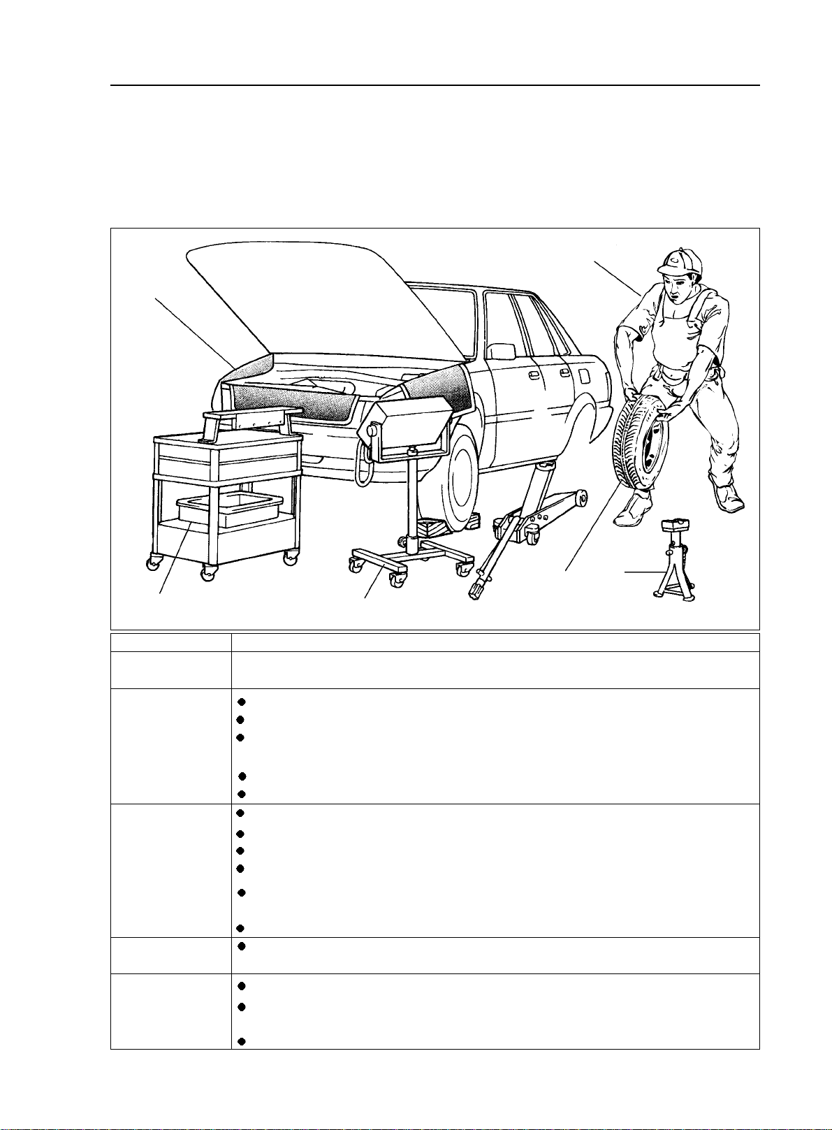
Vehicle Protection
Appearance
Safe Operation
Removal and
installation, disassemble and inspection
Prepare the tools and
measuring instrument
Removed parts
4
5
Before the work, place radiator fascia cloth, fender cloth, seat cover and mat.
Always wear clean uniform
Make sure to wear the helmet and safety shoe
when more than 2 persons work together, be sure to pay mutual attention to the safety.
when it is required to run the engine, you have to pay attention to the ventilation of the workshop.
When handling the high-temperature, rotating, moving and vibrating parts, be careful not to be scalded
or hurt.
When lifting the vehicle, safety stand should be used to support the specified position.
When lifting the vehicle, safety devices should be used.
The diagnosis requires full understanding of the trouble and effective operation.
Before the parts are removed, check the assembly for distortion and damage.
The diagnosis requires full understanding of the trouble and effective operation.
Before the parts are removed, check the assembly for distortion and damage.
If the structure is complicated, notes or marks should made to avoid mistake and impact of the part
function.
If needed, clean the removed parts and reassemble them after careful inspection.
Before the work, prepare the tool fixture, special tools, instrument, oil, workshop cloth and required
parts for replacement.
arrange the removed parts in correct sequence, do not confuse or contaminate them.
For non-reusable parts such as gasket, O ring and self-locking nut, replace them with new ones in
accordance with the instruction described in this manual.
Pick up replaced parts, put them in the containers, and show them to the customers.
3
Page 13

1-4
(2)Lift and support the vehicle
Be careful to lift and support the vehicle. Make sure that the vehicle is appropriately supported.
(3)Precoated Parts
a. Precoated parts are bolts, nuts, etc. that are coated with a seal
lock adhesive at the factory.
b. If a precoated part is retightened, loosened or caused to move
in any way, it must be recoated with the specified adhesive.
c. When reusing precoated parts, clean off the old adhesive and
dry with compressed air. Then apply the specified sealing adhesive
to the bolt, nut or threads.
Notice: the torque should achieve the lower limit of the allowed torque range.
d. The precoated parts should be kept intact for a period of time for induration based on the requirement of
the sealing adhesive.
(4)Gasket
If necessary, apply the sealant to the gasket to prevent disclosure.
(5)Bolt, nut and screw
Be careful to follow all torque specification and torque wrench should be used.
General Information - Repair Instruction
Sealing Adhesive
(6)Fuse
When replacing fuses, be sure the new fuse has the correct amperage rating. Do not exceed the rating or use one with a lower rating.
Illustration Symbol Part Name
Equal Rated Ampere Value
Fuse
Medium Current
Fuse
High Current Fuse
Page 14
General Information - Repair Instruction
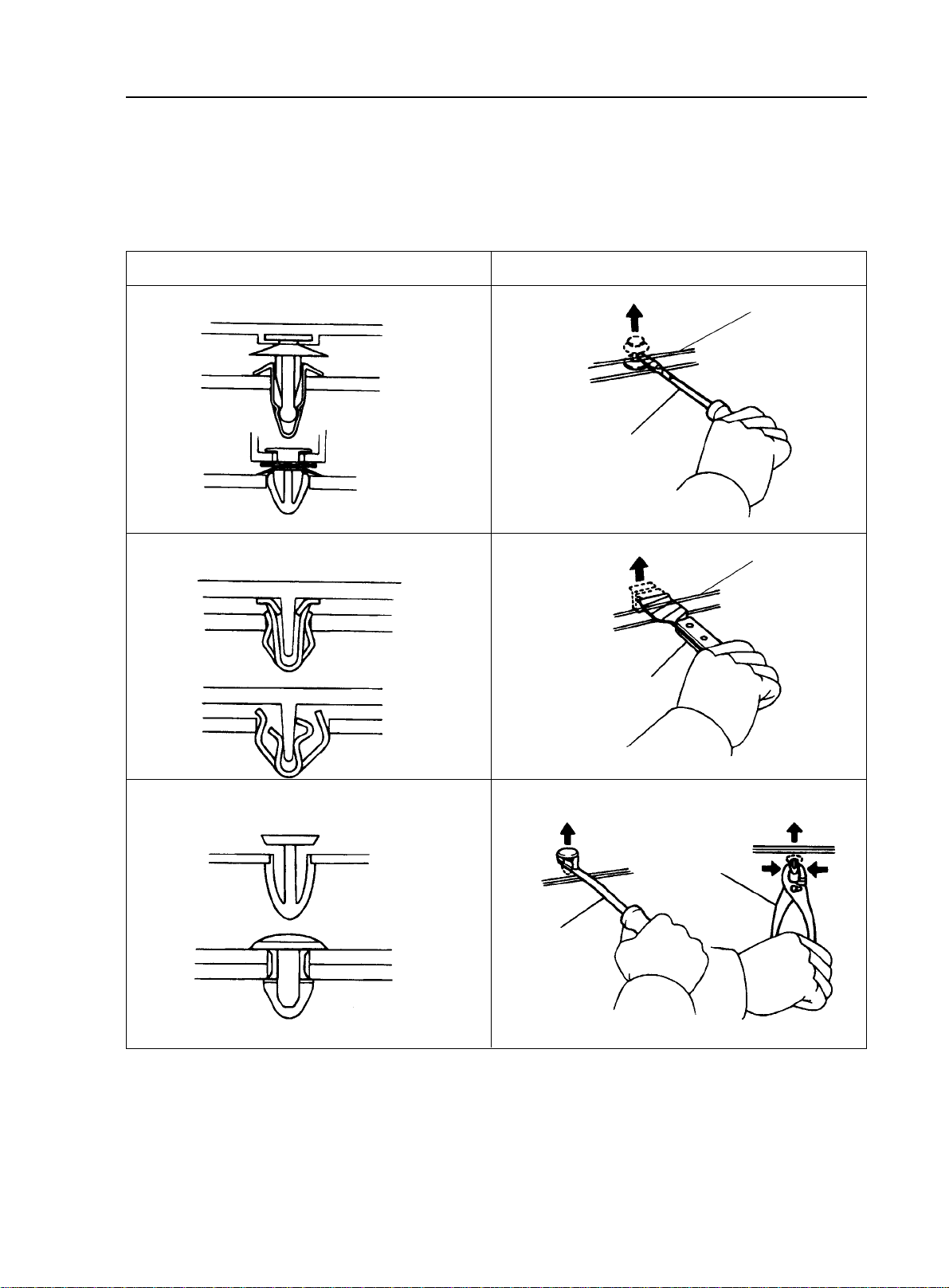
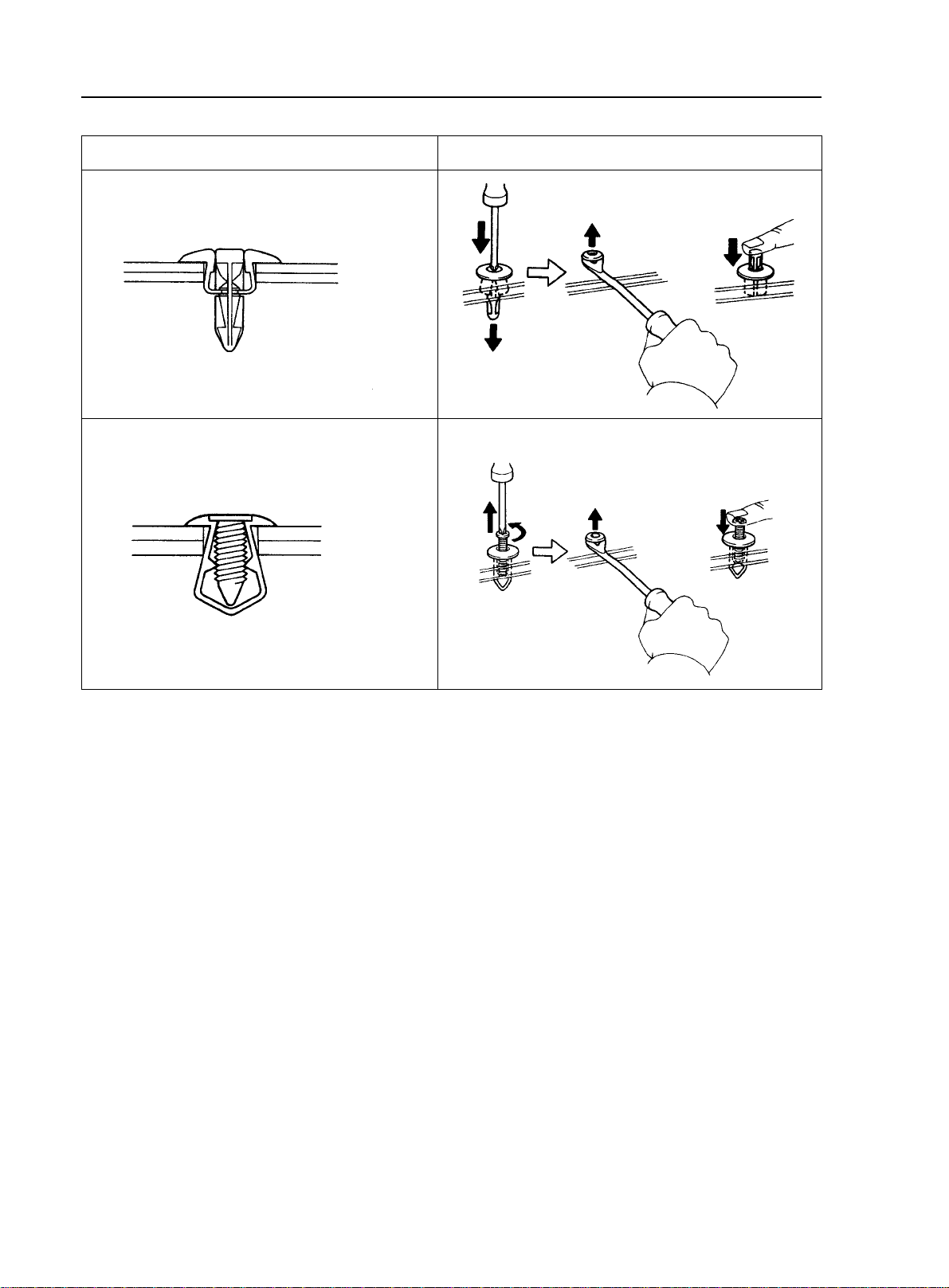
(7)Clip
The following illustration shows the typical removal and installation of the clip for body parts.
Tip:
If the clip is damaged during the operation, you have to replace it with a new one.
1-5
Illustration
Removal/installation
Protective Band
Screwdriver
Protective Band
Scraper
Clip Remover
Slip-joint
Pliers
Page 15
1-6
General Information - Repair Instruction
Illustration
Remove
Remove
Removal/installation
Install
Install
2. For Vehicles Equipped With SRS Airbag and Seat Belt Pretensioner
Tip: This is equipped with an SRS (Supplemental Restraint System), such as the driver airbag assembly,
front passenger airbag assembly airbag ECU and seat belt pretensioner. Failure to carry out service operations in
the correct sequence could cause the supplemental restraint system to unexpectedly deploy during servicing,
possibly leading to a serious accident. Further, if a mistake is made in servicing the supplemental restraint
system, it is possible the SRS may fail to operate when required. Before servicing (including removal or installation of parts, inspection or replacement), be sure to read the following items carefully, then follow the correct
procedure described in this manual.
(1) General Notice
a. Malfunction symptoms of the supplemental restraint system are difficult to confirm, so the diagnostic
trouble codes become the most important source of information when troubleshooting. When troubleshooting
the supplemental restraint system, always inspect the diagnostic trouble codes before disconnecting the battery.
b. Work must be started after 90 seconds from the time the ignition switch is turned to the "LOCK"
position and the negative (-) terminal cable is disconnected from the battery. (The supplemental restraint system
is equipped with a back--up power source so that if work is started within 90 seconds of disconnecting the
negative (-) terminal cable from the battery, the SRS may deploy.) When the negative (-) terminal cable is
disconnected from the battery, memory of the clock and audio systems will be cancelled. So before starting
work, make a record of the contents memorized by the each memory system. Then when work is finished, reset
the clock and audio systems as before. To avoid erasing the memory of each memory system, never use a backup power supply from another battery.
Page 16
General Information - Repair Instruction
1-7
c. Even in cases of a minor collision where the SRS does not deploy, the driver airbag assembly, front
passenger airbag assembly and seat belt pretensioner should be inspected.
d.
e. Never use SRS parts from another vehicle. When replacing parts, replace them with new parts.
f. Before repairs, remove the airbag ECU if shocks are likely to be applied to the sensor during repairs.
g. Never disassemble and repair the airbag ECU assembly, driver airbag assembly, front passenger airbag
assembly or seat belt pretensioner.
h. If the airbag ECU assembly, driver airbag assembly, front passenger airbag assembly or seat belt
pretensioner has been dropped, or if there are cracks, dents or other defects in the case, bracket or connector,
replace them with new ones.
i. Do not directly expose the airbag ECU assembly, driver airbag assembly, front passenger airbag assembly or seat belt pretensioner to hot air or flames.
j. Use a volt/ohmmeter with high impedance (10 k ohm/ V minimum) for troubleshooting of the electrical
circuit.
Information labels are attached to the periphery of the SRS components. Follow the instructions on the
notices.
k.
After work on the supplemental restraint system is completed, check the SRS warning light
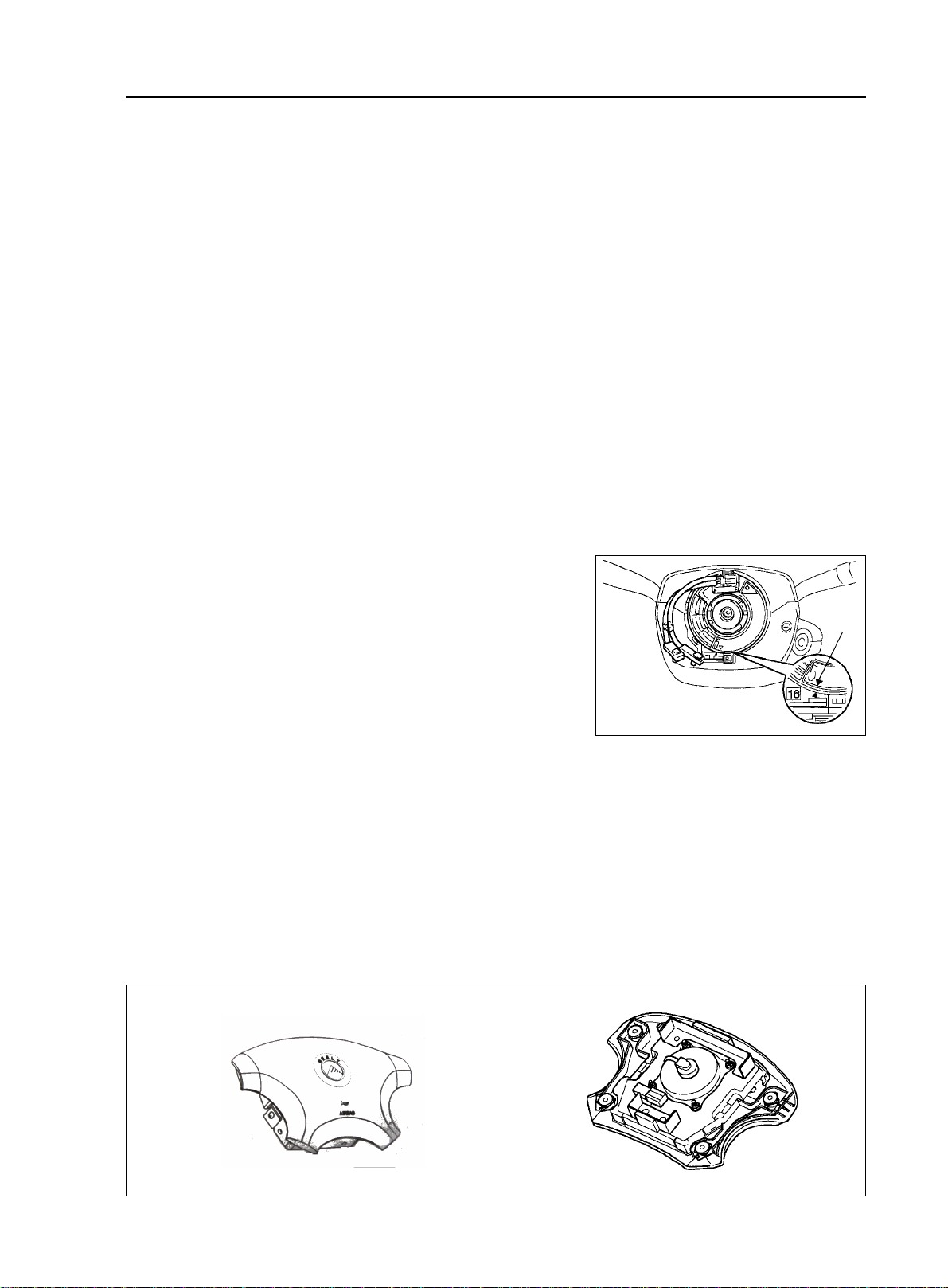
(2) Clock Spring (in combination switch)
The steering wheel must be fitted correctly to the steering column with the clock spring at the neutral position, otherwise clock
spring disconnection and other troubles may result.
Mark
(3) Driver Airbag Assembly
a. When removing the driver airbag assembly or handling a new driver airbag assembly, it should be placed
with the steering wheel top surface facing up. Storing the steering wheel with its top surface facing downward
may lead to a serious accident if the airbag deploys for some reason. In addition do not store a driver airbag
assembly on top of another one.
b. Never measure the resistance of the airbag squib. (This may cause the airbag to deploy, which is very
dangerous.)
c. Grease should not be applied to the driver airbag assembly and the pad should not be cleaned with
detergents of any kind.
Correct
Wrong
Page 17
1-8
d. Store the driver airbag assembly where the ambient temperature remains below 93°C , without
high humidity and away from electrical noise.
e. When using electric welding, first disconnect the airbag connector (yellow color and 2 pins) under the
steering column near the combination switch connector before starting work.
f. When disposing of a vehicle or the driver airbag assembly alone, the airbag should be deployed using an
SST before disposal. Perform the operation in a safe place away from electrical noise.
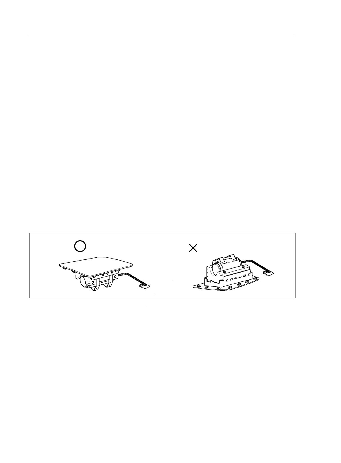
(4) Front Passenger Airbag Assembly
a. Always store a removed or new front passenger airbag assembly with the airbag rupture surface facing
up. Storing the airbag assembly with the airbag rupture surface facing down could cause a serious accident if the
airbag inflates.
b. Never measure the resistance of the airbag squib. (This may cause the airbag to deploy, which is very
dangerous.)
c. Grease should not be applied to the front passenger airbag assembly and the airbag door should not be
cleaned with detergents of any kind.
d. Store the airbag assembly where the ambient temperature remains below 93°C , without high humidity
and away from electrical noise.
e. When using electric welding, first disconnect the airbag connector (yellow color and 2 pins) installed on
the assembly before starting work.
f. When disposing of a vehicle or the airbag assembly alone, the airbag should be deployed using an SST
before disposal. Perform the operation in a safe place away from electrical noise.
General Information - Repair Instruction
Correct
(5) Seat Belt Pretensioner
a. Never measure the resistance of the seat belt pretensioner. (This may cause the seat belt pretensioner to
activate, which is very dangerous.)
b. Never disassemble the seat belt pretensioner.
c. Never install the seat belt pretensioner in another vehicle.
d. Store the seat belt pretensioner where the ambient temperature remains below 80°C and away from
electrical noise without high humidity.
e. When using electric welding, first disconnect the connector (yellow color and 2 pins) before starting
work.
f. When disposing of a vehicle or the seat belt pretensioner alone, the seat belt pretensioner should be
activated before disposal. Perform the operation in a safe place away from electrical noise.
g. The seat belt pretensioner is hot after activation, so let it cool down sufficiently before the disposal.
However never apply water to the seat belt pretensioner.
h. There should be no oil or water on the seat belt, no cleanser should be used to wash it.
Wrong
Page 18
General Information - Repair Instruction
1-9
(6) Airbag ECU
a. Never reuse the airbag ECU involved in a collision when the SRS has deployed.
b. The connectors to the airbag sensor assembly should be connected or disconnected with the airbag ECU
mounted on the floor. If the connectors are connected or disconnected while the airbag ECU is not mounted to
the floor, it could cause undesired inflation of the supplemental restraint system.
c. Work must be started after 60 seconds from the time the ignition switch is turned to the "LOCK" position
and the negative (-) terminal cable is disconnected from the battery, even if only loosing the set bolts of the
airbag ECU.
(7) Wire Harness and Connector
The SRS wire harness is integrated with the instrument panel wire harness assembly. All the connectors in
the system are a standard yellow color. If the SRS wire harness becomes disconnected or the connector becomes
broken due to an accident, etc., repair or replace it.
3. Electronic Control Device
(1) Removal of the battery terminal cable
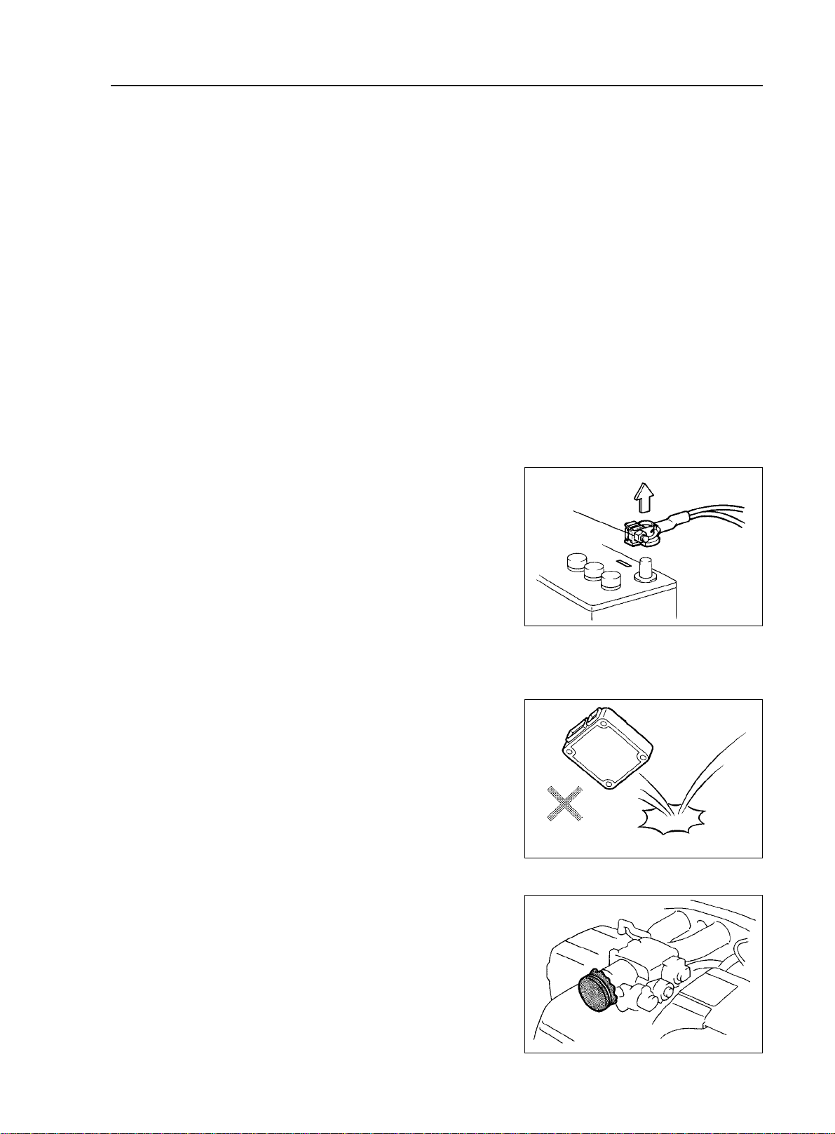
a. Before performing electrical servicing, disconnect the negative (-) cable from the battery in order to avoid short for burnout.
b. When disconnecting the terminal cable, turn of f the ignition
Negative(-)
Cable
and light switches, loosen the cable nut and raise the cable straight
up without twisting or prying it.
c. When disconnecting the terminal cable from the battery, all
information stored in the clock, radio and DTC shall be deleted,
therefore, these information shall be checked before disconnection.
(2) Processing of Electronic Parts
a. Do not open the cover or case of the ECU unless absolutely
necessary. (If the IC terminals are touched, the IC may be destroyed
by static electricity.)
b. To pull apart electrical connectors, pull on the connector itself,
not the wires.
c. Be careful not to drop electrical components, such as ECU
or relays. If they are dropped on a hard floor, they should be replaced
and not reused.
d. When steam cleaning an engine, protect the electronic
Wrong
components, air filter and emission-related components from water.
e. Never use an impact wrench to remove or install temperature switches or temperature sensors.
f. When checking continuity at the wire connector, insert the
tester probe carefully to prevent terminals from bending.
4. Remove and Installation of Engine Intake Parts
(1) If any metal scrap is mixed in the inlet pass, that may give
a bad effect to the engine.
(2) When removing and installing of the inlet system parts, close
Page 19
1-10
the opening of the removed inlet system parts and the engine with a
clean shop lag or gum tape.
(3)When installing the inlet system parts, check that there is no
mixing of a metal scrap.
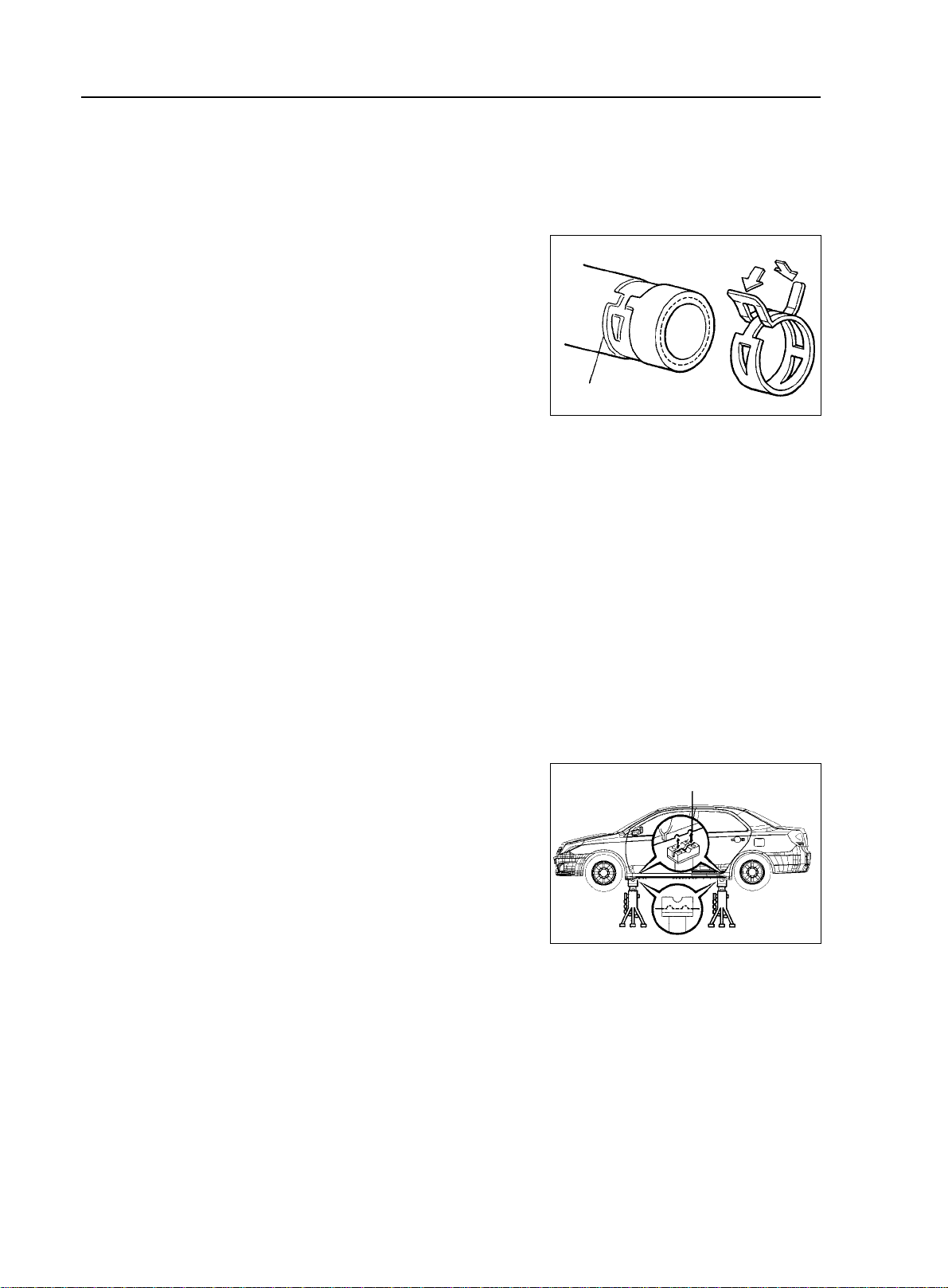
5. Handling of Hose Clamp
(1)Before removing the hose, check the clamp position to re-tighten
it for sure.
(2)Replace a deformed or dented clamp with a new one.
(3)In case of reusing the hose, install the clamp on the hose where
it has a clamp track.
(4)For a steel band circlip, make it adjust by adding force to the
arrow mark direction after the installation.
General Information - Repair Instruction
Steel Band Circlip
Clamp Trace
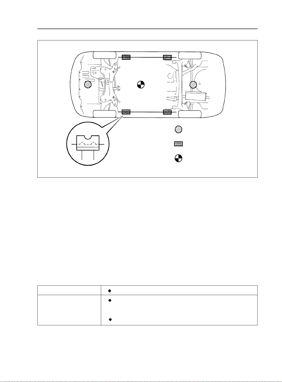
II. Vehicle Lift and Support Location
1. Vehicle Conditions To Be Under Attention During Lift
(1)Generally speaking, when being lifted, the vehicle should be empty, do not lift the heavily loaded vehicles.
(2)When removing heavy parts such as engine and transmission, the center of gravity of the vehicle will move.
Place balance weight to prevent the vehicle from rolling or use special jack to support the vehicle.
2. Precautions for Use of Four-tappet Lift
(1)follow the safe operation instruction described in this manual.
(2)do not damage the tire or rim.
(3)use wheel stopper to retain the vehicle.
3.Precautions for Use of Jack and Safety Stand
(1)always use the wheel stoppers when performing servicing on
level ground.
(2)use safety stand and rubber support as shown in the illustration.
(3)use the jack and safety stand to support specified location.
(4)When jacking up the front wheels of the vehicle, release the
park brake and place stoppers only behind the rear wheels. When
jacking up the rear wheels, place stoppers only before the front wheels.
(5)During the job, make sure to use safety stand instead of jack
only to support the vehicle.
(6)When only jacking up the front wheels or rear wheels, place
stoppers before or after the wheels touching the ground.
(7)when lowering the vehicle with its front wheels lifted, release
the park brake, and place the stopper only before the rear wheels.
When lowering the vehicle with its rear wheels lifted, place the stopper only after the front wheels.
Rubber Suport
Page 20
General Information - Repair Instruction
Jack Position
Center of Gravity of the Vehicle
1-11
Support Position
Jack Lifting Position
(empty load)
4. Precautions for Use of Swing Arm Type Lift
(1) follow the safe operation instruction described in this manual.
(2) use bracket with rubber support as shown in the illustration.
(3) make the center of gravity of the vehicle as close as possible to that of the lift ("L" should be smaller).
(4) adjust the bracker height, level the vehicle, align the groove of the bracket with the safety stand
support location.
(5) the arm should be locked during the job
(6) lift the vehicle until the tires become round.Swing the vehicle to make sure of stable vehicle.
5. Precautions for Use of Plate Type Lift
(1) follow the safe operation instruction described in this manual.
(2) use the support of the plate type lift.
(3) make sure to secure the vehicle in the specified position.
Left and right set position
Front and rear set position
•
Place the vehicle over the center of the lift.
•
Align the cushion gum ends of the plate with the attachment
lower ends (A, C).
•
Align the attachment upper end (B) with the front jack supporting point.
Page 21

1-12
General Information - Repair Instruction
(3)lift the vehicle until the tires become a little bit round. Swing the vehicle to make sure of stable vehicle.
Lift Center
Swing Arm Type Lifter
Plate T ype Lift
Cener of Gravity of the Vehicle
(Empty Load)
Support
rubber support
Support Dimension
Page 22
Vehicle Usage and Maintenance - Brief Introduction of Geely MK
Part II Vehicle Usage and Maintenance
Chapter 1 Brief Introduction of Geely MK
Section 1 Major Functional and Technical Data of MK Series.
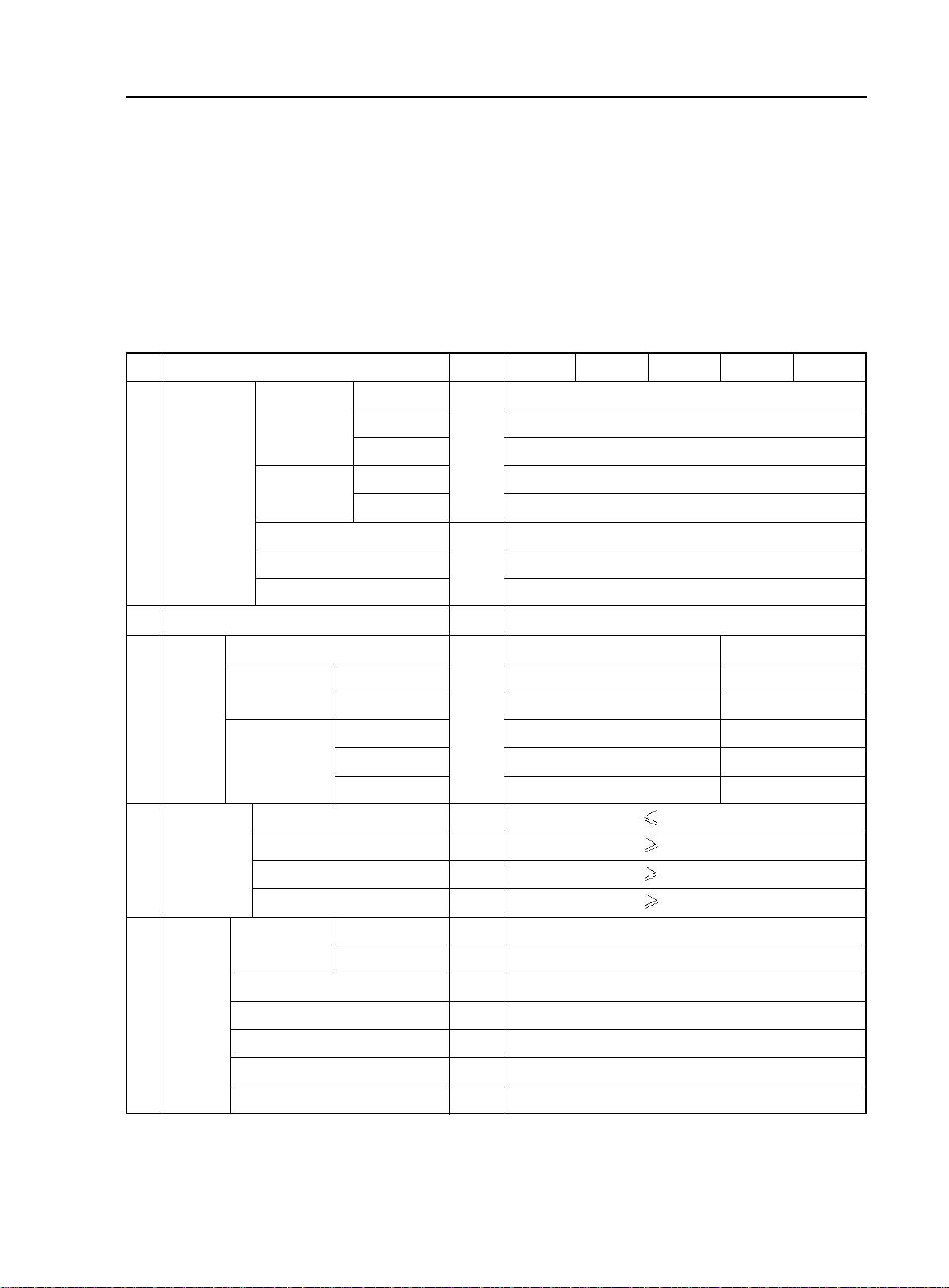
I. Vehicle performance and structural data
Table 1 vehicle data
2-1
ID
Dimension
1
2
Number of passengers
Curb weight
Weight
3
Road
4
adaptability
Curb
Gross Vehicle
W eight
Max turning angle
of front wheel
Item
Length
Dimension
Axle
Wheelbase
Front Suspension
Rear suspension
Minimum turning diameter
Minimum Ground Clearance
Approach angle
Deviation angle
Width
Height
Front
Rear
Front Axle
Rear Axle
V ehicle
Front
Rear
Left: Inner/out
Right: inner/out
Unit
mm
mm
person
kg
m
mm
°
°
°
°
JL7132U
JL7152U
1090(1040)
660(640)
430(400)
1460(1410)
780(760)
680(650)
JL7162U
4342
1692
1435
1450
1431
2502
848
992
10.4m
150mm
15°
20°
37.2°±2°/ 32°±2°
37.2°±2°/ 32°±2°
JL7132HU JL7152HU
5
1450(1455)
780(785)
1080
665
415
670
5
Wheel
Positioning
Front wheel leaning angle
Kingpin inward leaning angle
Kingpin rearward leaning angle
Left front wheel toe-in
Rear wheel outward
°
°
mm
°
°
-0°30'±45'
10°0'±45'
2°0'±45'
1±2mm
-0°56'±45'
Page 23
2-2
Brief Introduction of Geely MK - Major Functional and Technical Data of MK Series.
II. Introduction of major systems
Table 2 Models and technical data of major systems.
ID
1
Engine
2
3
Transmission
Item Description
Unit
Drive Type
Model
Type
Bore Diameter
Piston play
mm
mm
Displacement
Compression Ratio
Max Power
Max Torque
Idle Speed
kw/r/min
N.m/r/min
r/min
Ignition Sequence
minimum fuel consumption rate
Model
1st gear
2nd gear
3rd gear
4th gear
g/kw.h
JL7132U JL7152U JL7162U JL7132HU JL7152HU
›‹
Front Wheel Drive
2
4
MR479Q MR479QA MR481QA MR479Q MR479QA
In-line 4 cylinderIn-line 4 cylinder In-line 4 cylinder In-line 4 cylinder In-line 4 cylinder
78.7 78.7 81.0 78.7 78.7
69.0 77.0 77.0 69.0 77.0
L
1.342 1.498 1.587 1.342 1.498
9.3 : 1 9.8 : 1 9.6 : 1 9.3 : 1 9.8 : 1
63/6000 69/6000 78.7/6000 63/6000 69/6000
110/5200 128/3400 137/4400 110/5200 128/3400
800±50
800±50 800±50
800±50
800±50
1-3-4-2 1-3-4-2 1-3-4-2 1-3-4-2 1-3-4-2
259 279 269 259 279
JL-S160 JL-S160A JL-Z110 JL-Z130
3.182 3.087 3.087
1.895 1.634 1.634
1.250 1 1
0.909 / /
4
Clutch Type
5
Steering type
Braking
6
system
7
suspension
8
Tire
9
Fuel Tank Capacity
10
Body structure
5th gear
Reverse gear
Final Drive Ratio
Model
Booster type
Front
Rear
Specification
Tire pressure
Wheel
KPa
L
0.703 / /
3.083 2.29 2.29
4.308 3.317 3.317
Single disc, Plate and dry Spring
Hydraulic Gear-rack
Hydraulic, X-type pipe
Vacuum booster, Front Wheel Disc, Rear Wheel Drum
McPherson suspension strut system
Twist beam independent suspension system
85/60R15(1175/65R14)
230(Front)/210(Rear)
Aluminum 15X6J (Iron 14X5 1/2JJ)
45
Unitary construction body
/
Page 24
Brief Introduction of Geely MK - Vehicle Configuration
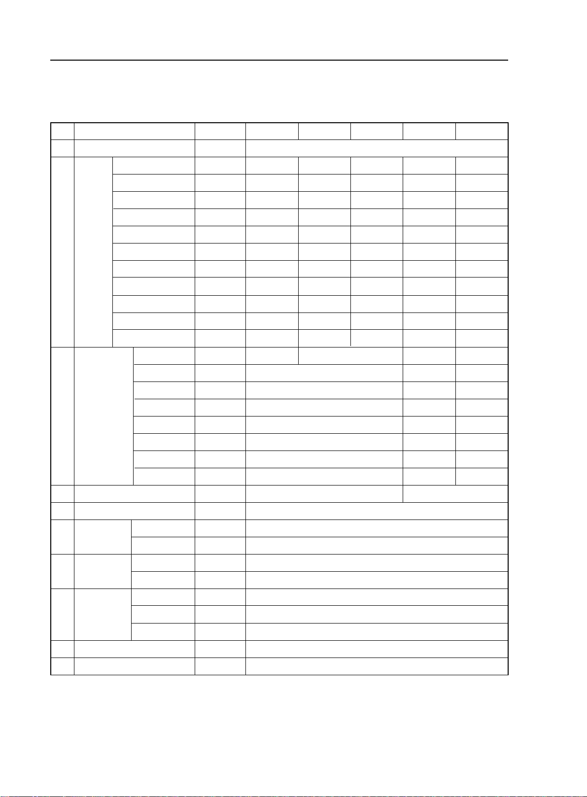
Table 3 Power Performance Parameter
No.
Item Name
Unit
JL7132U JL7152U JL7162U JL7132HU JL7152HU
2-3
1
Maximum vehicle speed
Acceleration time within the fourth gear from 30km/h to 120km/h
2
Acceleration time from 0-100km/h
3
Minimum stable vehicle speed within the fourth gear
4
Maximum gradeability
5
Table 4 Economic Performance Parameter
No.
1
Fuel consumption at constant speed (60km/h)
2
Fuel consumption at constant speed (90km/h)
3
Coasting distance (fully loaded, initial speed 50km/h)
Item Name
Unit
L/100km
L/100km
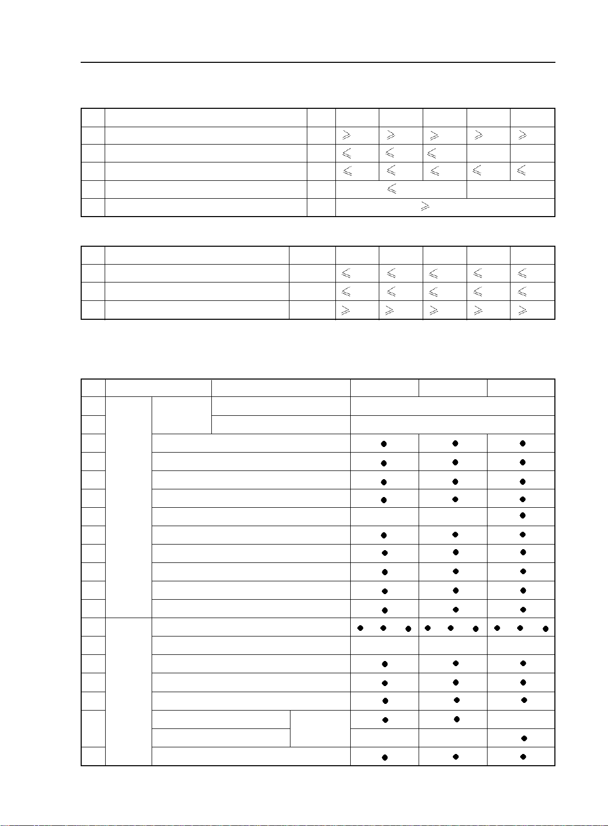
Section 2 Vehicle Configuration
No.
1
2
Item Name
Body color
Type
Common color
Uncommon color
km/h
km/h
%
m
33
s
s
20
30
18
25
JL7132U JL7152U JL7162U
4.5
4.6 5.0
6.2
550
550
Standard Comfortable Luxury
Chinese red, snow mountain white, pearl black, sky blue, ribbon silver
Crystal diamond silver, golden sand green, pineapple yellow
155175165155
28
16.5
30
22
165
//
20
/
JL7132HU JL7152HU
4.7
6.3
550
6.66.2
550
5.1
6.7
550
3
4
5
6
7
8
9
10
11
12
13
14
15
16
17
18
Exterior
device
Interior
device
Front chromeplated trim molding
Diamond-shape headlight
Crystal diamond taillight
Highly penetrable front fog light
Green heat insulating four-door glass
Scuff strip with same color as that of the body
Aluminum alloy wheel rim
Tire (185/60R15) (with spare tire)
Retractive antenna (A pillar)
Bumper with same color as that of the body
Light color (T)deep color(S)mixed color(R)interior trim
Central control panel
Firry red Firry red
A/C outlet vent + trim ring
Chromeplated inner handle
Sun shade (with ticket folder)
High-grade flannelette
Seat
Luxury leather
/ /
/ / / /
Titanium silver
19
Front seat headrest front and rear angle/height adjustable function
Page 25
2-4
Brief Introduction of Geely MK - Vehicle Configuration
No.
20
21
22
23
24
25
26
27
28
29
30
31
32
33
34
35
36
37
38
39
40
41
42
43
44
45
46
47
48
49
50
51
Interior
device
Electric
device
Safety
device
Item Name
Front seat back trash bag
6/4 split foldable rear seat
Cable-controlled oil tank cap
Cable-controlled trunk
plastic
leather
Power window (with one-touch function)
Remote control central door lock
Power rearview mirror with turn signal light
Smart remote control key (control the closure of the
door and window and the delay of the vehicle lights)
Adjustable intermittent wiper
On-board handsfree handset
Anti-clamp retractive power window
Central pointer type instrument
Temperature display
Hi-fi CD audio
MP3 function
Speaker
Freon-free A/C system
Air cleaner
ABS + EBD
Driver side airbag
Front passenger side airbag
Telescopic steering column
Front seat belt pretensioner /height adjustable
Rear row triple-person seat belt
Anti-glaze inner rearview mirror
Anti-explosion and anti-leak plastic oil tank
Rear windshield defroster function
High-mounted stop light
Four-door anti-impact beam
Digital display rear parking radar
Adjustable steering wheel
Type
Follow me home light delay system
Standard Comfortable Luxury
Single Disc Single Disc 6 Discs
6 speakers (2 Tweeters) 6 speakers (2 Tweeters) 6 speakers (2 Tweeters)
Remark: - denote standard configuration Z - standard C - comfortable D - luxury S - dark interior trim
T - light colored interior trim R - mixed color
Page 26

Brief Introduction of Geely MK - Main Vehicle Test Technical Specification
Section 3 Main Vehicle Test Technical Specification
2-5
Item
Inspection
line items
Description
Front wheel outward leaning angle
Kingpin inward leaning angle
Kingpin rearward leaning angle
Left front wheel toe-in (mm)
Rear wheel outward leaning angle
% of braking total power vs. gross vehicle weight
% of front wheel braking power vs. front axle load
% of gap between left and right wheel brake power vs. the
greater braking power of them two
rolling resistance of each wheel should not be larger than the axle load by
parking brake total power should be lighter than the test vehicle weight by
sliding distance of front/rear wheels
when vehicle speed meter shows 40km/h, vehicle speed
monitor indicates
brightness of left/right headlamps
tolerance of close lamps is
tolerance of distant lamps is
(0.6-0.8)H, H refers to the central
height of headlamps.
-0°30'± 45'
10°0'± 45'
2°0'± 45'
-0°56'± 45'
60% (no load),
60% (no load, and full load)
20%(Front Axis),
24%(Rear Axis)
33.3 Km/h-42.1Km/h
Harsh brake at 50km/h. the stop distance is
Rain test. 100 points is full mark. Minus one point for each
Specification
1±2
50% (full load)
5%
20%
2 m/km
15000 cd
10cm/10m
19m
Regular
quality
inspection
items
Emission
seepage. Minus 3 points for slow seepage 3 points, and minus
6 for a quick seepage. The limit of vehicle sealing is
Check leaks of the vehicle. When vehicle has run 50km, stop it and
inspect for leaks. Check if there is oil/water marks at static joints,
or if there is oil/water drops dripping down at dynamic joints
nose
10min after the vehicle is stopped, there is a leak; if there is oil/
water marks/drops, but it does not drip down, there is seepage.
Measure the temperature of transmission oil inspection hole.
Usually it is not higher than ambient temperature.
Check the surface temperature of wheel trim column. Usually
it is no higher than ambient temperature.
vehicle should be slightly steering insufficient i.e. driving on
a circle with same steering wheel angle, and accelerate from
low to high speed, the diameter of the circle increases gradually.
Maximum front wheel turning angle (inner/outer)
Specification: GB18352.3-2005
93 points
Daily inspection and smell with
70°C
40°C
Inspect regularly
37.2°±2°/ 32°±2°
Page 27

2-6
Usage and Maintenance of MK Series - Usage of MK Series
Chapter 2 Usage and Maintenance of MK Series
Section 1 Usage of MK Series
1. Instrument Panel Overview
1.Instrument Panel Outlet Vent
2. Instrument Panel
3.Upper Glove Compartment
(Front Passenger Airbag Cover)
4.Sunshade
5.Dome Light And Sunroof
Switch
6.Inside Rearview Mirror
7.Glove Box
8. Power Window Regulator
Switch
9. Manual Transmission Shift
Lever Or Automatic Transmission Shift Lever
10.Parking Brake Control Lever
11.Engine Hood Release Handle
12.Power Window Lock
13.Power Door Lock Switch
1.Left Combination Switch
2.Right Combination Switch
3.Display
4.Audio
5.Short-Distance Odometer
Adjustment Button
6.Instrument Panel Brightness
Adjustment Switch
7.Hazard Warning Light
8.A/C Control Panel
9.Ash Tray
10.Defroster Switch
11.Cigarette Lighter
12.”A/C“ Switch
13.Ignition Switch
14.Tilt Steering Adjustment
Handle
15.Theft-Deterrent Indicator
16.Power Outside Rearview
Mirror Control Switch
Page 28
Usage and Maintenance of MK Series - Usage of MK Series
2-7
2.How to use ignition switch
(1) LOCK when key is at this position, it can be pulled out and inserted in easily. The function of this position
is to lock steering wheel. If the key cannot be turned from LOCK to ACC, please rotate the steering wheel slightly
while turning the ignition key.
(2) ACC radio and cigarette lighter is turned on when key is at this position.
(3) ON when key is at this position, the following indicator is on: battery charging, ABS, brake fluid level,
park brake, engine coolant temperature, engine MIL, airbag oil pressure.
(4) START Turn the key to this position to start the engine. When engine is started, release the key
immediately. It returns to ON automatically. When engine is on, do not turn the key to this position.
Notice:
(1) Do not pull the key out or turn it to LOCK before the car is fully stopped, or there will be dangers caused
by locking steering wheel or disabling some safety functions.
(2) It is prohibited to drive the car with engine turned off to ensure functioning of braking and steering booster.
(3) Do not let the key stay at ON for a long time when engine is off, or the battery fully discharged.
(4) Shift to neutral gear before ignition key is switched to START.
(5) Turn the steering wheel lightly after the car is fully stopped to make sure it is locked.
3.Unlock Steering Wheel
How to unlock steering wheel: insert ignition key, turn the steering wheel lightly and switch the ignition key.
Steering wheel is unlocked.
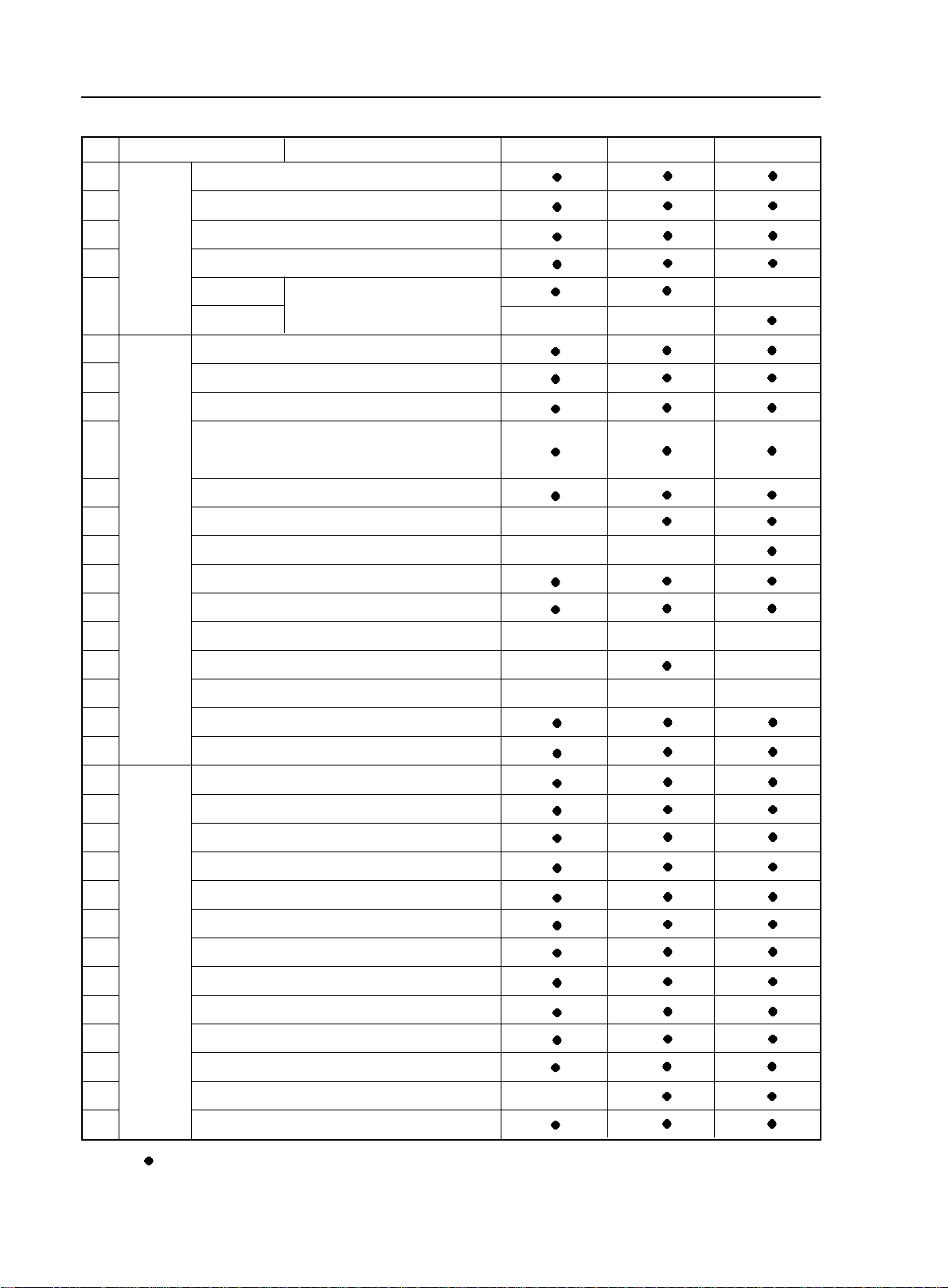
4.Adjust seat position
Seat back angle and cushion angle of front seats in MK-1 sedan can be adjusted.
(1) Adjust seat back angle
Turn around adjusting handle, and adjust seat back to appro
priate position.
(2) Move seat forward or backward
Steps:
a. pull adjusting handler up
b. Move the seat forward or backward, and adjust the seat to
appropriate position.
c. Put the handler down and move the seat again till it is
locked.
Attention: adjust the seat only when the car is fully stopped
to ensure safety.
(3) Front head rest can be adjusted in two ways.
Push the head rest from back to front, there are three fixed
positions to lock.If pushed over the final locking position,the
head rest can return to the original position after hand
withdraws.
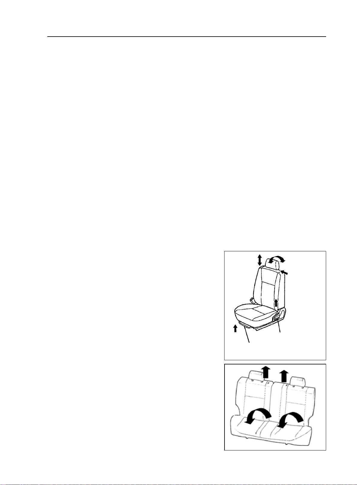
(4) Fold Rear Row Seat
The seat back can be tilted forward so that the trunk will be
used to the last degree.
a. Remove the head rest
b. Unlock the seatback and fold it down.
Split seatback can be folded separately on demand.
2
Move seat forward or backward angle
1
Adjust seat back angle
Page 29

2-8
5. Actions to ensure vehicle working condition and safe driving.
(1) To make sure of driving safety, execute the following inspections before driving.
a. Inspect fuel level, and add fuel when necessary.
b. Inspect illuminating lights, turning signal lights, braking signal lights to see if they work.
c.Check the position of rearview mirrors.
d.Check if breaking system functions well.
e.Check if glass of all the lights, windshield is clean.
(2) Regular inspection Perform the following regular inspections to ensure the vehicle work condition and
driving safety.
a. Check engine oil level. Park the vehicle on flat road; check the oil level with engine oil level indicator
at least 10 minutes after the engine is stopped. The oil level should be between the two marks. If it is
lower than "L" mark, add some oil; if it is higher than "F" mark, there is excessive oil, so release it.
Or investigate the cause of high oil level.
The volume between the lowest oil level ("L") and highest oil level ("F") is 1.4L.
b. Check engine coolant level. Check the level when the engine is cool. The coolant level should be between
LOW and FULL. If it is lower than "LOW", add coolant. If the coolant is much lower than Min (every
coolant fill is more than 1L) or the vehicle requires frequent fills,investigate if there is any problem with
the cooling system.
To keep the function of coolant, replace coolant every two years at the beginning of cold winter.
c. Check brake and clutch fluid level (sharing a reservoir). Brake fluid level should between the Max and
Min marks. And it is better to keep it close to the Max mark. Add fluid in time when there is not enough
fluid.
d. Check power steering fluid tank. The level should be between Max and Min marks. Refill when there
is not enough steering fluid to avoid pump stuck. It is strictly prohibited to run the vehicle without
steering fluid in any circumstances.
e. Check the charging status of battery and if the connection of battery wires is good.
f. Check tire status and pressure
g. Check the status of wipers.
(3) Observe warning lights and indicators on instrument panel.
a. There are various warning lights and indicators on the instrument panel of MK-1 sedans to indicate and
warn abnormal operations of engine, braking, and charging systems.
b. Pay attention to these lights when driving.When the warning lights or indicators are on,stop the vehicle,
check the vehicle and resolve the causes to make sure the vehicle works well or drives safely.
6. Correct ways to use new cars
Reliability and stability of components in new cars and recently repaired cars still need to be confirmed, and
relative parts are not broken-in, so they must be used carefully to ensure driving safety, to avoid abnormal damage,
and to extend the useful life of the car.
(1) Before driving inspection The following inspections must be performed on the new car to ensure car safety
and reliable operation:
a. Check if instrument panel, warning lights, and indicator, front and rear wiper and washer, and switches
work.
b. Check if the fastening of driveline, steering, suspension, wheels and other connection parts is good.
Usage and Maintenance of MK Series - Usage of MK Series
Page 30

Usage and Maintenance of MK Series - Usage of MK Series
c. Check levels of braking fluid, engine coolant, engine oil, transmission oil, power steering fluid, and
washing fluid to see if there is any leaking.
d. Inspect if brake pedal, clutch pedal, accelerator pedal, transmission shifter, steering wheel, choke are
loose or stuck. The free travel of clutch pedal is 5~15mm, the free travel of brake pedal is 1~6mm and
the free play of steering wheel is less than 30mm(measurement point at margin of steering wheel). if it
is out of this normal range, the clutch needs to be tuned.
e. Inspect if the connection of battery, lamps and signal lights are normal, and if the wire routing and
position are correct and not loose.
f. Inspect if the tire pressure is correct.
(2) On-road inspection If the inspection result of the above items is good, start the engine and test the car on
road, and perform the following inspections.
a. Acceleration pedal, see if the operation is smooth and if it is loose.
b. Clutch, see if there is any stuck or abnormal noise, and slip when driving.
c. Transmission,check if shifting is smooth,or rough and wrong shifting.Inspect if the display of A/T
shift lever is normal.
d. Steering, check if steering is light and smooth, and if the steering wheel turns back after steering.
e. Brake pedal, apply brake pedal to check if the braking functions well when vehicle speed is at
40km/h and if the vehicle runs off track.
f. Park brake, when parking brake handler is pulled, there should be 6~9 clicking sounds. Pull park brake
when vehicle is running at the speed of 20km/h and transmission is at neutral gear to see if it brakes.
g. Vehicle speed meter, observe the vehicle speed meter while driving. When speed changes, check if the
indicator is moving steadily or shakes.
h. Heating and air-conditioning.Try every control button to see if both heating and cooling system work
well.
i. Abnormal noise, listen carefully to see if there is any abnormal noise from engine, drive line system or
any other parts of the vehicle at a steady speed and during accelerating, and decelerating.
(3) Inspection after test ride check if there is anything abnormal in the vehicle while driving and conduct the
following inspections after the vehicle is parked.
a. Check electrical fan When engine coolant temperature is beyond 92.5°C, the radiator fan should be
running; When A/C is on and the pressure of refrigerant is more than 1.5 cooling ton, air conditioning
cooling fan should be running.
b. Check headlamp, method: park the car 5m away from the inspection surface (inspection board, curtain,
or wall) to the front bumper, and check if the beam from headlamp is good. The upper level if headlamp
should be 540mm above the ground, and the distance between headlamps on the two sides is 900mm.
c. Inspect engine idle speed,idle speed of hot engine is 800r/min±50r/min,when A/C compressor works,
the idle speed should be 900r/min±50r/min. If idle speed is abnormal, adjust the idle speed adjust
ment screw to adjust it.
(4) Usage of new cars in breaking-in period Follow the instructions below in the first 1500~2500km breaking
mileage to avoid wear and abnormal damage in breaking-in period, and to improve vehicle performance, fuel
economy and to extend vehicle useful life.
a. Drive steadily during breaking-in; do not accelerate harshly to avoid running engine at high speed.
Engine should not exceed 4500r/min in any gears. Especially at the early stage of breaking-in, vehicle
2-9
Page 31

2-10
must be running at medium speed without load. Increase the speed and load gradually with the
accumulation of breaking-in mileage.
b. Because the brake plat is not broken in on a new vehicle,in order to ensure safety and reduce wear,avoid
harsh brake, and brake for multiple times to break in the brake plate faster.
c. It is better to avoid driving vehicle on steep roads or in bad conditions during breaking-in period.
d. Pay special attention to engine coolant temperature meter and oil pressure meter.Check engine oil level
frequently and make sure engine works in normal temperature and good lubrication.
e. Maintain the vehicle strictly according to first-time maintenance requirements to bring the vehicle into
normal usage life under good condition.
7.vehicle towing
There are towing facilities both in the front and rear end of MK-1 sedan for towing other vehicles and being towed.
To ensure safety, pay attention to the following instructions when towing.
(1) Towing car Towing car should be started and shifted steadily.The speed should be no more than 40km/h.
(2) Follow the instructions below when being towed:
a. Steering system of the vehicle being towed works well.
b. Braking system of the vehicle being towed works well or it cannot be towed with a rope and must be
towed with the towing shaft instead.
c. Release park brake and shift the transmission to neutral gear when the vehicle is being towed.
d. Turn the ignition switch to ACC to allow turning signal lights,braking indicator to be turned on when
necessary.
e. The towing rope must be tensioned in the towing process.
f. If the purpose of towing is to start the engine, shift the transmission to the 2nd or 3rd gear to increase
engine speed. It is good for starting the engine.
8. Instructions to save fuel when using the vehicle
(1) Reasonable load Do not store useless articles in luggage compartment because they consumes fuel for
nothing.
(2) Correct driving style Instructions as follows:
a. When engine is started, do not heat it but press the accelerator pedal slightly, drive the vehicle slowly
and accelerate gradually.
b. Shift to higher gears when driving to allow the engine to work at appropriate engine speed and avoid
running the engine at low or high speed. The engine speed should be higher than 2500r/min when
driving, and higher than 3000r/min when up-shifting.
c. Keep the vehicle speed stable, and avoid harsh acceleration and frequent braking.
d. Pay attention to vehicle speed. Drive at high speed results in excessive fuel consumption.
(3) Organize vehicle usage well Pay attention to the following two instructions.
a. Organize vehicle usage time and avoid short trips. Because at the beginning when the vehicle is started
(around 1km), the engine has not reached its efficiency point, and the fuel consumption doubles
compared to regular.
b. Select a good driving route, avoid driving through the city or blocks with heavy traffic.
(4) Keep the vehicle under good work condition Strictly follow instructions to maintain the vehicle to make
sure the vehicle is under good technical working condition, and inspect and replace key parts that affect vehicle
fuel consumptions. For example:
Usage and Maintenance of MK Series - Usage of MK Series
Page 32

Usage and Maintenance of MK Series - Usage of MK Series
a. Keep air filter clean, Block of air filter affects engine air induction efficiency and increases fuel
consumption. So it must be cleaned and replaced in time.
b. Keep ignition system under good work condition. Bad connection or electricity leak of ignition coil and
power distributor or inappropriate gap or carbon residue of spark plug decreases ignition power supply
and efficiency, which leads to engine fuel consumption increase. So they need regular inspection and
repair to keep their good work condition.
c. Fuel feeding system works well. Often check if fuel feeder pipe leaks, and check if injectors and other
parts perform well on regular basis (electrical injection engines).
d. Keep regular tire pressure. If the tire pressure is not enough, vehicle rolling resistance increases and
engine fuel consumption increases accordingly. So tire pressure must be checked on time (around once
a week).
2-11
Page 33

2-12
Usage and Maintenance of MK Series - Maintenance Category and Content of MK Sedan
Section 2 Maintenance Category and Content of MK Sedan
As the vehicle is being used, its technical performance changes as the mileage accumulates and being affected by
various factors, which results in decrease of power, fuel economy, safety, and increase of emission pollutions,
noise and incidents. So timely maintenance during vehicle usage eliminates potential risks and prevents incidents
from happening, improves vehicle integrity and technical functionality, and prolongs useful life of the vehicle.
According to the vehicle technical requirements and usage history, maintenance of freedom Cruiser sedan can be
classified into several categories.
I. first time maintenance
First time maintenance is also called breaking-in maintenance. It is performed when the vehicle mileage has
accumulated to 1500~2500km in breaking-in period. First time maintenance must be conducted at the appointed
service shops. It includes:
1. Check if there is any leak in engine, transmission, and differential. Fix if there is any.
2. Replace engine oil filter, engine oil and ATF for A/T.
3. Check the level of engine coolant, braking fluid, windshield washing fluid, power steering fluid and if there
is any leak. Refill if the level is too low and repair if there is any leak.
4. Check if there is any damage in triangle arm and ball joint, connection ball joint, triangle arm flexible hinge,
or the ball joint is loose. If there is, fix or replace it.
5. Check if the drive shaft dust cover is damaged. If there is, replace it.
6. Check if there is any leak in steering mechanism, or front and rear absorber and fix it there is any.
7. Check the tire pressure, front 230kpa, and rear 210kpa.
II. Regular maintenance
After first time maintenance, the vehicle is in regular usage life. During regular use, the vehicle needs to be
maintained regularly according to the way it is used in.
1.Regular maintenance for vehicles used under extreme bad conditions. Any of the condition below is defined
as extreme bad condition:
(1) Frequent start.
(2) Often drive the vehicle in dusty circumstances.
(3) Drive the vehicle in hot areas (such as in summer in the south).
(4) Often drive in cold areas (often runs short trips, engine temperate cannot reach regular work temperature).
Vehicles ran under extreme bad conditions need to be maintained every 5000km.
2. Regular maintenance for vehicles Vehicles that have not been through extreme bad conditions need to be
maintained every 7500km.
Regular maintenance is required to be performed at Geely service shop, too.
List of parts that need to be replaced regularly is in table 1.
Maintenance timetable is in table2.
III. Geely maintenance program
Geely recommends following Geely maintenance program.
The intervals of maintenance schedules are determined by mileage meter or time periods. Maintain the vehicle
when either meets the schedule. For details, please refer to the schedule.
Page 34

Usage and Maintenance of MK Series - Maintenance Category and Content of MK Sedan
For servicing items whose deadlines have expired, they should be maintained at the same intervals as before. The
intervals are recorded in maintenance schedule.
Rubber hoses
Used in cooling and heating system, braking and fuel-feeding systems should be inspected by qualified Geely
technicians according to Geely maintenance schedule.
There are all very important maintenance items. Hoses must be replaced immediately should there be any aging
or damage. Please pay attention, rubber hoses age as time goes by, and they may have problems of inflation, wear,
or crack.
Special Tips
If the vehicle is driven under one or more of the following circumstances, the maintenance items should be
carried out more frequently. See attached maintenance schedule.
A Road condition
1. drive on rough, muddy or skiddy roads
2. drive on dusty roads.
B driving condition
1. Repeat driving within 8km a few times, or when the outdoor temperature is below 0 degree centigrade.
2. Idle the car drive at a low speed for a long time, such as police car, taxi, or door to door delivery vehicles.
3. Continuously drive the car at high speed for more than 2 hours (80% of the max speed).
2-13
IV. Regular inspections
1. weekly schedule
inspect engine oil level and cleanness
inspect engine coolant level
inspect brake fluid level
inspect windshield wash fluid level
inspect power steering fluid level
2. monthly inspections
inspect water pump belt
inspect electrolyte level in battery
inspect tire air pressure and wear
inspect steering wheel
inspect brake
inspect acceleration pedal
3. inspection when driving (low speed)
inspect speed meter and water temperature
check steering wheel power and if vehicle runs off-track
check if the front wheels skid or swing
inspect if brake functions or if the vehicle runs off-track when brake is functioning
4. other inspection items
Eliminate problems immediately when there is anything abnormal
Page 35

2-14
Usage and Maintenance of MK Series - Maintenance Category and Content of MK Sedan
V. Table 1 List of parts to be replaced regularly
System
Braking
System
Driveline
Steering System
A/C System
Engine
Parts need to be replaced regularly
1
Brake master cylinder cup valve and dust cover
2
Brake master cylinder cup
3
Brake hose
4
Brake caliper valve
5
Brake booster rubber
6
Brake booster vacuum hose
7
Brake fluid
8
MT Transmission oil
9
AT Transmission oil
10
Steering fluid
11
Air Cleaner
12
Air c leaner f ilter
13
14
15
16
17
18
19
Lubricant
Oil filter
Fuel filter
Coolant
All hoses
Canister
Timing belt
(API) SG or above
(Table 1)
Intervals
Every 2 years (or as required)
Every 2 years (or as required)
Every 2 years (or as required)
Every 4 years (or as required)
Every 2 years (or as required)
Every 4 years (or as required)
Every 2 years,or 40000km (or as required)
Every 2 years,or 40000km (or as required)
Every 2 years,or 40000km (or as required)
Every 2 years,or 40000km (or as required)
To be cleaned every 10,000km and changed
every 30,000km (or as required)
First 2500km or 2 months. Every 7500km or
6 months afterward (or as required)
First 2500km or 2 months. Every 7500km or
6 months afterward (or as required)
Every 5000km (or as required)
Every 40000km (or as required)
Every year (or as required)
Every 2 years (or as required)
Every 60000km (or as required)
Every 120000km (or as required)
Wedge belt (including the power steering pump,
20
air conditioner compressor and generator belts)
21
PCV system
22
Spark plug
The intervals in the part list are for cars driven under normal condition. If the car is driven in special circumstances,
the replacement can be advanced from the schedule above.
Every 50000km (or as required)
Every 20000km or 12 months (or as required)
Every 20000km (or as required)
Page 36

Usage and Maintenance of MK Series - Maintenance Category and Content of MK Sedan
2-15
VI. Table 2 Maintenance Timetable of Geely Freedom Cruiser Sedan
Maintain the vehicle when either mileage or time has reached maintenance requirements. User should keep
maintaining the vehicle to no less than 100000km. User can send the vehicle for inspection and repair in advance
if it has been through special conditions.
System Inspection item
Steering
System
Drive
line
Drive
Train
Braking
System
Steering
Wheel
Steering
Gear
Steering
Link and
Joint
Knuckle
Front
Wheel
Wheel
Clutch
Manual
Transmission
Automatic
Transmission
Driveshaft
Brake
Pedal
Parking
Brake
Steering-wheel Play,Fastening and abnormal noise
Operation
Oil Leak
Fastening
Fastening,abnormal noise and damage
Steering link,joint,rack and dust boot
crack and damage
Abnormal noise at a joint
Wheel adjustment
Left and right rotation angle
Trie pressure
Tire crack and damage
Tire thread and uneven wear
Metal dust,stone and foreign material
Loose hub nut and bolt
Front wheel bearing abnormal noise
Rear wheel bearing abnormal noise
Free play
Operation
Oil leak and oil level
Operation system abnormal noise
Replace oil
Replace ATF
Oil leak and oil level
Joint fastening
Universal joint,dust root crack and damage
Spline abnormal noise
Universal joint abnormal nosie
Free play and Function
Function
Operating travel
Function
Parking brake cable fastening,abnormal noise and damage
X1000km
Year
oooo
oooo
oooo
oooo
oooo
oooo
oooo
oooo
......Replace
o
ooo
o
o
o
o
o
o
o
o
Table 2
o
o
o
o
oo
o
o
o
oo
oo
oo
oo
o
o
oo
o
o
o
oo
oo
oo
o
o
o
o
o
o oo
o oo
o oo
o oo
oo
o oo
oo
oo
oo
oo
oo
o oo
o oo
o oo
oo
......Inspect
o
7. 5 15 22.5 30 37.5 45 52.5 60 67.5 75
0.5 1 1.5 2 2.5 3 3.5 4 4.5 5
o
o
o
o
oo
o
o
o
o
o
o
o
o
o
o
o
o
o
o
o
o
o
o
o
o
o
o
o
o
o
o
o
o
o
o
o
o
o
o
o
o
Page 37

2-16
Usage and Maintenance of MK Series - Maintenance Category and Content of MK Sedan
o
......Inspect
......Replace
System Inspection item
Brake
Booster
Brake reservoir level
Function
Master brake cylinder,brake
cylinder and brakecalipel
Braking
System
Suspension
System
Brake
Drum and
Shoe
Brake Disc and
Brake Lining
Spring
Attachment
and Joint
Suspension
Arm and
Shock
Absorber
Clearance between brake drum and brake lining
Brake shoe sliding part and brake lining wear
Brake drum wear and damage
Brake lining wear
Brake disc wear and damage
Damage
Fastening and damage of attachment
Abnormal noise at a joint
Noise from joint,damage to arm and
shock absorber fluid leak and damage
Abnormal noise at fixture
Spark plug working status
Lgnition time
Ignition System
Distributor air gap
Electrical
System
Battery
Wiring Harnee and Clip
Lighting
Comblned Instrument
Horn,Wiper and
W asher
Distributor cap condition
Connection
Fastening and damage of joints
Function
Function
Function
X1000km
Year
Brake liguid leak
7. 5 15 22.5 30 37.5 45 52.5 60 67.5 75
0.5 1 1.5 2 2.5 3 3.5 4 4.5 5
o o oo
Function wear and damage
oo o oo
o oo
o oo
o oo
o oo
o oo
o oo
o oo
o oo
o oo
o
oo
o
o
o o
o
o
oo
o
o
o
o
oo
o
o
oo
oo
oo
oo
oo
oo
ooo o oo
oo
o
o
o
o
ooo o oo
oo
o
o
o o
o
o
o
o
oo
o o
o
o
Engine
Body
and
Accessory
Defrost and
Power Door Lock
Starting performance,abnormal noise,
Engine
General
Status
Door and Trunk Lock
Hood
Seat
Others
idle and acceleration
Valve clearance
Oil leak
Function
o o oo
Lock Function
Fastening abnormal noise and damage
Seat and seat belt status
Lubrication
o oo
o oo
o oo
o
o
oo
o
oo
oo
oo
o
o
o
o
o
Page 38

Usage and Maintenance of MK Series - Maintenance Category and Content of MK Sedan
VII . Additional maintenance schedule
Vehicles run in special circumstances require higher frequency of maintenance as listed below.
A-1: driving on bumpy, muddy or melted snow road.
Inspection of the brake friction wafer and braking drum
o
Inspection of the braking pad and braking disc
o
Inspection of the brake piping and hose
o
Inspection of the transmit shaft ball and joint and dust shield
o
Inspection of the drive shaft cover
o
Inspection of the steering wheel, connecting rod and steering gear
o
box oil
Inspection of the front and rear suspension devices
o
Screwing down the bolts and nuts of the chassis and vehicle body
o
A-2: driving on dusty road
Replacement of engine oil
o
Replacement of engine oil filter
o
Inspection and replacement of air filter
o
Inspection of the brake friction wafer and braking drum
o
Inspection of the braking pad and braking disc
o
Replacement of the air conditioner filter
o
Every 5,000km (kilometer) or every 6 months
Every 5,000km (kilometer) or every 6 months
Every 2,500km (kilometer) or every 3 months
Every 10,000 km (kilometer) or every 6 months
Every 5,000km (kilometer) or every 3 months
Every 10,000km (kilometer)
Every 10,000 km (kilometer) or every 6 months
Every 5,000km (kilometer) or every 3 months
Driving for 1000 km (kilometer) for the first time and
then every 10,000 km or every 6 months
Every 10,000 km (kilometer) or every 6 months
Every 10,000 km (kilometer) or every 12 months
Every 5,000km (kilometer) or every 3 months
Every 10,000 km (kilometer) or every 6 months
Every 10,000 km (kilometer) or every 6 months
2-17
B-1: repeated short-distance driving and outer air temperature under zero within 8km (kilometer)
Replacement of engine oil
o
Replacement of engine oil filter
o
B-2: long-term empty run and / or long-distance driving with low speed, such as police wagon, taxi or automobile delivering
goods to the customers etc
Inspection of the brake friction wafer and braking drum
o
Inspection of the braking pad and braking disc
o
B-3: continuous high-speed driving for more than 2 hours (80% of the maximum vehicle speed or above)
Replacement of driving axle oil of the manual transmission
o
Inspection or replacement of the driving axle fluid of the
o
automatic transmission
Every 2,500km (kilometer) or every 3 months
Every 5,000km (kilometer) or every 6 months
Every 10,000 km (kilometer) or every 6 months
Every 5,000km (kilometer) or every 3 months
Every 40,000km (kilometer) or every 48 months
Every 40,000km (kilometer) or every 24 months
Page 39

2-18
Usage and Maintenance of MK Series - Daily Maintenance of MK Sedan
Section 3 Daily Maintenance of MK Sedan
Daily maintenance means operation of vehicle regular inspection, cleaning, fastening, and refilling according to
vehicle usage and condition on the basis of regular maintenance to make sure the vehicle is at good status. Daily
maintenance can be performed by driver or professional automotive mechanics in daily use of vehicle. But some
of the items must be conducted by professional mechanics at service shops.
1. Maintenance of air cleaner
Air cleaner filters the air that is coming into engine for the first time. Dust and other dirt filtered out gathers in the
induction tube. Air cleaner filters a lot of dust and dirty, so it must be cleaned in time.
2. Maintenance of air filter
Air filter does not only filter the dust and dirt in the air, but also keeps smooth ventilation. Its status has great effects
on the fuel economy and power of the engine, so it must be checked and maintained in time.
Before it is time to replace air filter, maintain it. Remove the filter, knock it with hand or stick to get rid of dust
on the filter and remove dirt inside the filter cover according to the cleanness of the road that the vehicle usually
runs on.
ATTENTION: do not clean the filter with wet cloth. Fasten the filter well when installing it back.
3. Maintenance of battery
Battery is used to start the vehicle and supply power to electrical facilities. Its status directly affects the regular
usage of the vehicle, especially for vehicles equipped with electrical controlled facilities. Keeping the battery in
good technical status and connections is especially important. It is necessary to often perform the following
inspections and maintenance in regular usage:
(1) Clean the outside of battery Inspect if the battery case or cover surface is dirty or has dirt, oil, or other dirty
things regularly. Clean it and keep the surface dry to avoid electrical leak caused by cover deformation.
(2) Check battery connections Bad connection between battery electrode and cable results in low engine start
speed which makes it difficult to start the vehicle or the vehicle cannot be started because of low output voltage
from battery. Loose connection at battery end leads to damage of electrical components and loss of trouble code
and other information stored in RAM of the computer system as a result of low voltage. Therefore, it is necessary
to check if the connection of cables on the battery electrode is good. When it is found loose, it must be fastened.
If there is any rust, the cables must be loosened, washed clean and be connected again.
4. Maintenance of tires and wheels
(1) Keeping tires and wheels under good condition is very important to vehicle fuel consumption and driving
safety. Therefore, inspect and maintain the tires regularly. Every 10000 km, the wheels should be adjusted. Follow
the sequence in picture 3:
Judge if there is any hidden problems in vehicle chassis mechanism by observing wear in different places, and
finding out the hidden problems does not only help you to understand
the technical status of the vehicle, but also benefits driving safety.
a. Serious wear on both edges of tire tread, means tires often
work with low tire pressure.
b. Wear of middle of the tire tread is mainly because the tires
are used with high tire pressure.This kind of wear shortens
the useful life of tires, and may result in sudden flat tire
when the vehicle runs on uneven road surface or meets any
obstacles.
Page 40

Usage and Maintenance of MK Series - Daily Maintenance of MK Sedan
c. Wavy wear on the tread is related to its quality and positioning of the wheels. Find out the root cause
and eliminate any problems.
d. Serious wear on the outer side beside the tread of steering wheels means the wheel outward leaning angle
is too big; wear on the inner side beside the tread means the leaning angle is too small.
e. When the toe-in value is getting smaller, the wear on the outer side of tread is in shape of saws. On the
contrary, when the inner side has the saw shape wear means the toe-in value is too big.
(2) Maintenance
a. Keep the tire pressure to specified value under any circumstances. Measure the pressure on cold tire
b. Check tire pressure regularly, and remove any indented objects that may stick through the tires.
c. Avoid oil, gasoline, and brake fluid on tires.
d. When replaced with new tires, the wheels need to be balanced and adjusted again. Or the vehicle may
shake when running at high speed and bear abnormal wear.
e. Do not mix tires of different structure, pattern, or brand on one vehicle.
(3) Tire specification and pressure
Tire Specification Tire Pressure (KPa)
Front Tire 185/60R15 84H or 175/65R14 82H 230
Rear Tire 185/60R15 84H or 175/65R14 82H 210
2-19
(4) Tire wear limits
When the wear limit mark on tire shows up as the tire wears, it must be replaced with new tires (wear limit mark
indicates the thickness of tire pattern is 1.6mm).
5. Maintenance of wiper and washer
Status of wiper and washer directly influences windshield and driver's view. So, pay attention to wipers and
washers.
(1) Wiper Check if the wiper blade has any damage, deformation, which affects windshield wiping quality
and if the wiper works well. If wiper blade does not wipe well or the wiper does not work well, fix or replace it
in time.
(2) Washer Check washing fluid level in the tank, and refill when necessary. To get best washing effects, use
specified washing fluid, refill slowly, and pay attention not to mix it with any dirt. Mix the washing fluid with some
alcohol in winter to avoid freezing.
6. inspect and adjust headlamp
Incorrect beam of the headlamps affects safety of driving in the dark. So they must be inspected regularly, and be
adjusted when necessary.
7. Maintenance of inside the vehicle
The major content of maintenance inside the vehicle is cleaning, to keep the vehicle clean and provide fresh and
pleasant driving circumstance. The key points of indoor cleaning are:
(1) Ways to remove stains Get rid of dust before trying to remove stains, and then apply appropriate cleansing,
and wipe the stains off with clean, soft, and not too wet cloth repeatedly.
(2) Cleansing It is better to remove stains on textile and man-made leather with hydro solvent made from soap
fluid and surface active agent. Be careful to avoid using any cleansing because they may corrode the synthetic
decoration materials more or less. Ball-pen and lipstick marks can be removed with alcohol, grease can be removed
with low Ron value gasoline, and chocolate and sugar stains can be cleaned with ammonia spirit, asphalt must be
cleaned with special cleansing.
Page 41

2-20
(3) Long time exposure to sun damages interior. So it is better to use covers on upper seat backs, and rear
separation board that are exposed to sun.
8. Maintenance of body exterior
Body exterior is to keep body cleanness and brightness to give the impression of beauty and comfort, and to avoid
rust and abnormal paint peeling off. The key points of body maintenances are:
(1) Wash body using the method below:
a. Wash the dirty things off the body by pressurized water, and then clean the body with
soft cloth of sponge from up to down.
b. Dry body surface with good white cloth. Apply brake pedal several times when driving
after the car is washed to get rid of water in braking system.
c. Do not wipe the body when it is dry. Do not clean paint surface and glass with gasoline,
coal oil, narkosid, strong lye or alcohol.
(2) Cleaning windshield glass
Do not use silicon-bronze radical products. To get better cleaning effects, use special glass cleanser.
(3) Cleaning asphalt on the body
Do not peel the asphalt off from body or bumper, but use special cleanser
(4) Paint
Scratches or slight damages can be fixed with special paint spray. It dries in the air.
(5) Cleaning exterior decoration parts and aluminum parts.
Wash with water with soap fluid or cleanser, and wash with clean water. To keep the gloss of painted surface,
wax on the surface after it is dry.
(6) Polish and wax the body paint polishing and waxing keeps the body bright and pretty, and protects the paint
as well.
a. Polish in winter. Make sure the vehicle body is absolutely clean and dry before
polishing, polish with fluid or milky wax.
b. Vehicle body must be absolutely dry and clean before waxing. Use waxing tools (soft
table tissue or smooth cotton cloth) to cover the body paint surface evenly with wax.
Check if the vehicle body is covered by wax: spray some water onto the paint surface,
if water drops are formed, that surface is waxed, otherwise, clean the surface and wax
it again. Attention: do not wax under sun, or in cold weather.
Attention
1) When using high pressure washing machine, do not point the washing sprayer to transmission, steering
mechanism and other rubber protection parts, or exterior decoration parts, roof welding lines, heat radiator
or engine compartment.
2) The bottom of vehicle body is made of anti-corrosion material,and has been through anti-corrosion process.
After the vehicle has been running frequently on roads de-frozen with salt for some time, clean engine
compartment and lower part of vehicle body and take some protection actions.
Usage and Maintenance of MK Series - Daily Maintenance of MK Sedan
Page 42

Engine Engine Assembly
-
3-1
Part III Engine
Chpater 1 Engine Assembly
Information about engine accessories in MK-1 Car Maintenance Manual deals with only that concerned with a
complete car. Please refer to separated Maintenance Manual for information about the engine body. Engines
concerned are MR479Q, MR479QA and MR481QA.
Section 1 Engine Inspection
1. Check the engine oil
(1) Check the oil level.
(2) Start the engine, and reach warm-up temperature.
(3) Shut the engine down, wait for 3-5min, and check the oil level.
(4) Check whether the oil level is in within the range marked by the scale; if it is lower than the limit (mark
L), fill oil to mark F.
(5) Keep the oil clean without any coolant or petrol mixed in and with appropriate viscosity.
2. Change oil.
(1) Start the engine. When normal temperature is reached, shut down the engine.
(2) Open the oil cap, remove the oil drain plug, and drain the oil.
(3) Tighten the oil drain plug to a specified torque 54N.m.
(4) Fill fresh oil into the crank case with oil quantity 2.8L in case of the filter not changed, 3.0L in case of the
filter changed and 3.5L in case of the dry filter.
(5) Fit on the oil filling cap.
(6) Start the engine.
(7) Shut down the engine and check the oil quantity, and fill oil to the mark F on the oil scale if necessary.
3. Replace the oil filter.
(1) Remove the oil filter.
(2) Before mounting the oil filter, apply a small quantity of engine oil to the O-ring of the new oil filter.
(3) Tight the oil filter to a specified torque (12.7N.m).
(4) Start the engine, and check whether there is any leakage
(5) Shut down the engine, check the oil quantity and fill as required.
4. Oil selection
Oil over PAI SG grade is preferred.
SAE10W-30 or SAE10W-40 is preferred, and ASE5W-30 is used in cold region in the winter.
Note: For the best effect and the greatest safety, it is advisable to use the following lubrication oil.
a. Meet the requirements of API level.
b. Select proper SAE viscosity rating within expected ambient temperature.
The lubrication oil that can not meet the requirements of SAE viscosity and API label at the same time is not
allowed.
5. Check the coolant.
(1) After the engine is cooled down, remove the radiator cover.
Page 43

3-2
Engine Assembly Engine Inspection
-
(2) Make sure that the coolant level is above the neck of the radiator.
(3) Put the radiator cover in place, pressurize to 2.0Mpa, and keep the pressure for 1minute unless the coolant
leaks. (Mount a tester on the radiator cover, start the engine, and then shut down under a pressure 2.0Mpa).
(4) Check whether the coolant quantity in the dilatation can is between the mark "Low" and "Full".
(5) Check whether the radiator cover is clean; test whether the opening pressure of the main valve is 107.8KPa
with a radiator cover tester. The minimum opening pressure is 58.5KPa.
6. Check the battery.
(1) The terminal voltage of the battery is 12.5-12.9V at 20°C, and charge when the voltage value is less than
the specified value. Check whether the fusible cutout and the fuse are loose, corrosive or on.
7. Check the air filter.
(1) Whether the cover, the case or the element of the filter is distorted, corroded or damaged.
(2) Whether the air hose is damaged.
(3) Whether the air chamber is distorted or damaged.
(4) Whether the air filter element is blocked, polluted or damaged. If the filter element is blocked slightly,
remove the dirt by blowing the element from above.
(5) Whether there is any pollutant or dirt on the air filter support.
8. Check the spark plug.
(1) Spark generation.
a. Disconnect the coupling of the injector.
b. Remove the spark plug from the secondary wire.
c. Remove the spark plug.
d. Connect the spark plug to the secondary wire.
e. Ground the spark plug.
f. Start the engine, and check whether spark is generated.
Prompt: The starting time is not more than 1-2s.
(2) Clean the spark plug: The air pressure is not greater than 588kp and the time is not more than 20s.
(3) Check whether the thread and the insulator of the spark plug are damaged. Replace if necessary.
(4) Check the electrode gap of the spark plug: 0.8±0.1mm for MR479Q and MR479QA; 1±0.05mm for
MR481QA.
9. Check the driving belt.
Belt distortion (see Table 1):
Belt pressure: 98N
Water
pump
3
1
Alternator
Table
New belt mm Used belt mm
Generator drive belt 7~9 11.5-13.5
Power steering belt 5~6 6~8
Air conditioner belt 6.5~7 8~9
Power steering
pump
Crank
2
Measure belt looseness
Note:
Check the belt distortion at the specified point (see Figure 1-1).
When mounting a new belt, set the tensioning force to specified value.
After the belt has been operated more than 5 minutes, check and ensure the distortion not exceeding specified
Figure 1-1
value.
Compressor
Page 44

Engine Assembly Engine Inspection
-
After the belt is re-mounted and operates more than 5 minutes, check the distortion based on old belt
distortion.
Check the tensioning force and the distortion of the V-belt after the crankshaft of the engine has rotated 2
turns.
10. Check the ignition timing (see Figure 1-2).
(1) Start the engine for warming up.
(2) When using the portable tester:
Connect the portable tester to the fault diagnosis socket
(DLC3).
Ignition timing:
before the top dead center when idling.
10°±20'
Prompt:
Please refer to the operating manual of the portable tester for
Figure 1-2
detail.
(3) When not using the portable tester:
a.Short the terminals 13(TC) and 4(CG) of the fault diagnosis socket(DLC3) with special service tool(SST).
Attention:
Make sure to connect correctly, or else the engine can be damaged.
Switch off all the electric systems.
Check when the cooling fan motor is disconnected.
b.Check the ignition timing with a timing light.
Ignition timing: 10°±20' before the top dead center when idling.
Note:
(a) Check the ignition timing, and the transmission should be set to the neutral position.
(b) Keep the engine speed at 1,000-1,300r/min for 5s and check when idling.
(c) Remove the special tool on the fault diagnosis socket.
(d) When the engine speed rises, the advance angle of ignition timing will increase.
(e) Remove the timing light.
11. Check the engine idle (see Figure 1-3).
(1) The engine warms up.
(2) When using the portable tester: Connect the portable tester to the fault diagnosis socket (DLC3).
Tip: Please refer to the operating manual of the portable tester for
detail.
Tachometer
(3) When not using the portable tester:
Connect the test pen of the tachometer to the terminal 9(TAC) of
the fault diagnosis socket (DLC3) with special tool (SST). (see
Figure 1-3).
(4) Check the idling speed: 800±50r/min.
Attention:
Check idle when the cooling fan motor is disconnected.
Switch off all the electric accessories and air conditioners.
Battery
Figure 1-3
3-3
Page 45

3-4
12. Check the compressing pressure (see Figure 1-4).
(1) Warm up and switch off the engine.
(2) Remove the secondary wire.
(3) Remove the spark plug.
(4) Check the compressing pressure in the cylinder.
a.Insert the pressure gauge into the spark plug bore.
b. Throttle widely opens.
c. Rotate the engine crankshaft and measure the compressing
pressure (see Table 2).
Engine Assembly Engine Inspection
-
Figure 1-4
Table 2
Cylinder compressing pressure (KPa)
Pressure difference range of cylinders of this model (KPa)
Minimum compressing pressure (KPa)
MR479Q MR479QA MR481QA
1250 1320 1360
100
980
Attention:
The electric quantity in the battery should be always enough, and the engine speed should be not less than
250r/min.
Check the compressing pressure in other cylinders in the same way.
Measure as soon as possible.
(5) If the compressing pressure in more than one cylinder is relatively low, fill a bit engine oil to the cylinder
through the spark plug bore, and repeat step a to c to check.
Tip:
If the compressing pressure is increased after the oil is filled, the piston ring or the cylinder may be worn or
damaged.
If the pressure is still low, the valve may be jammed or badly sealed, or the washer may be leaked.
13. Check CO/HC.
(1) Start the engine.
(2) Keep the engine running at a speed of 2500 r/min for about 180s.
(3) During idling, insert the test bar of CO/HC instrument into the exhaust pipe about 40cm depth at least.
(4) Check the concentration of emission of CO/HC at idle speed and at a speed of 2500 r/min respectively.
Tip:
Measure within 3 minutes.
Test the concentration of emission and lambda value of CO/HC at idle speed and at a speed of 2500 r/min
respectively according to GB18352.3-2005 standard.
(5) If the concentration of CO/HC is not up to standard, carry out fault diagnosis by following the steps below.
(1) Check oxygen sensor.
(2) Refer to Table 3 to find possible causes, check and repair.
Page 46

CO
Normal
Low
High
Engine Assembly Removal of the Engine Assembly from the Vehicle
HC
High
High
High
-
Problems
Bad idle speed
Bad idle speed
(HC reading fluctuates)
Bad idle speed
(Black smoke exhausts)
Causes
1. Ignition fault:
Incorrect ignition timing;
Dirt, short circuit, or incorrect spark plug gap.
2. Incorrect valve gap.
3. Suction and exhaust valve leak.
4. Cylinder leaks.
1. Vacuum leaks.
PCV pipe . manifold;
Idle speed control valve;
Brake booster pipeline.
2. Spark lacks since the mixed gas is too thin.
1. Air filter is blocked.
2. PCV valve is blocked.
3. EFI system fails.
ECU fails.
Pressure regulator of fuel oil is out of order.
Water temperature sensor does not work.
Suction pressure/temperature sensor fails.
Injector fails.
The throttle position sensor fails.
3-5
Table 3
Section 2 Removal of the Engine Assembly from the Vehicle
1. Avoid petrol overflowing (Disconnect from the fuel tank).
2. Remove the front wheel.
3. Discharge the coolant completely.
4. Remove the air filter assembly with hose (see Figure 1-5).
(1) Disconnect the joint of the temperature sensor and the wire
plug.
(2) Disconnect the vent duct from the hose of the air filter.
(3) Release the wire clip bolt on the air filter.
(4) Disconnect the hose of the air filter from the throttle body.
(5) Remove 3 bolts and the air filter assemblies.
5. Remove the battery.
6. Remove the fuel pipe sub-assembly.
7. Disconnect the water pipe; disconnect the water outlet pipe of the
heater from the air conditioner pipe.
8. Release the nut and remove the accelerator control cable.
Figure 1-5
Page 47

3-6
Engine Assembly Removal of the Engine Assembly from the Vehicle
-
9. Remove the oil tank assembly of the power steering pump (with power steering).
10. Remove the radiator assembly.
11. Disconnect the harness.
12. Disengage the steering column assembly.
13. Disengage No.2 steering countershaft assembly (see Figure 1-6).
Remove the cover sheet of the steering column on the car body.
14. Remove the exhaust pipe assembly in the front.
15. Remove the nut on the front hub (Parts on the other side are
Mark
disassembled in the same way).
16. Disconnect the speed sensor on the front wheel (with ABS).
17. Disengage the ball assembly of the steering tie rod.
18. Disengage the front suspension arm sub-assembly.
19. Disengage the front drive shaft assembly (see Figure 1-7).
20. Disengage the front drive shaft from the hub with a plastic
hammer.
21. Disconnect the shift cable or the tie-rod assembly of the
transmission.
22. Disconnect the clutch wheel cylinder assembly or the clutch
cable (M/T).
Figure 1-6
23. Remove the engine assembly together with the drive bridge:
(1) Hoist the engine a bit with lifting equipment;
(2) Remove 2 bolts, and disengage the right support of the engine
(see Figure 1-8);
(3) Remove 2 bolts, and disengage the left support of the engine;
(4) Remove one bolt, 3 nuts and disengage the rear support of the
engine;
(5) Remove the engine together with the drive bridge and place
them on the floor;
(6) Lift the body.
Figure 1-7
Figure 1-8
Page 48

Engine Assembly Drive Belt Replacement
-
Section 3 Drive Belt Replacement
1. Remove the V-belt of the generator (see Figure 1-9).
(1) Release bolts A and B.
(2) Release the bolt C and remove the V-belt.
3-7
2. Remove the V-belt (from the air conditioner compressor to the
crankshaft sheave (see Figure 1-10).
(1) Release the nut A.
(2) Release the bolt B, and remove the V-belt.
3. Remove the belt of the water pump.
Release bolts A and B, and remove V-belt.
4. Mount the V-belt of the water pump.
Mount the V-belt on the sheave briefly.
5. Adjust the V-belt of the steering pump (see Figure 1-11).
(1) Adjust the tension of the power steering belt, and fasten the
bolt B.
(2) Fasten the bolt A.
Torque: 39N.m
Figure 1-9
Figure 1-10
Figure 1-11
6. Mount No.1 V-belt (from the air conditioner compressor to the crankshaft sheave). (See Figure 1-10).
7. Adjust No.1 V-belt (from the air conditioner compressor to the crankshaft sheave).
(1) Adjust the tension of the belt of the air conditioner by fastening the bolt B.
(2) Fasten the nut A. Torque: 39N.m.
8. Mount the V-belt of the generator (see Figure 1-9).
9. Adjust the V-belt of the generator.
Fasten the bolt A, and then the bolt B.
Torque: 18N.m for bolt A, 58N.m for bolt B.
10. Check distortion and tension of the driving belt.
Page 49

3-8
Component View
Air filter assembly with hose
Engine Mechanical Engine Components
-
Chapter 2 Engine Mechanical
Section 1 Engine Components
Accelerator control cable assemble
Water inlet pipe of heater
Water outlet pipe of heater
Fuel oil sub-assembly
Upside of radiator support
Engine cover lock assembly
Radiator assembly
Clutch release assembly
Water inlet pipe of radiator
Water outlet pipe of radiator
Output pipe of oil cooler
Input pipe of oil cooler
Transmission control cable assembly
Transmission control cable assembly
Starter assembly
Battery
Suitable for 1.5L/1.6L(Tight coupling)
Suitable for 1.3L/1.5L(Non-tight coupling)
Figure 2-1
Page 50

Component View
Engine Mechanical Engine Components
-
3-9
V-belt of fan and generator
V-belt of vane pump (with power
steering mechanism)
No.1 V -belt
Separator of the right
engine support
Steering
column
cover
Glove case door
assembly
Steering column
assembly
Mounting support of the left engine
: Non-reusable parts
Left front drive shaft assembly
Front exhaust pipe assembly
Washer
Figure 2-2
Left front speed sensor (with ABS)
Left nut on the front hub
Washer
Page 51

3-10
Component View
Engine Mechanical Engine Components
Fuel oil pipe subassembly
Fuel oil pipe clip
-
Secondary wire
Vent duct
Fastener of
No.1
injector
Throttle assembly
adjusting support
with power steering
Water temperature sensor
Crankshaft position sensor
O-ring
Injector
O-ring
Vane pump assembly with
power steering
Washer
Pump support with
power steering
Knock sensor
Suction manifold
Washer
Water inlet pipe housing
Water outlet
pipe housing
No.1 heat shield of
exhaust manifold
Bypass hose
Rear end housing
Hex. flange
M6¡Á50
bolt
Ignition coil
Ignition coil
installation bracket
Bolt M8¡Á31
Generator assembly
No.1 support of compressor
Air conditioner compressor
Oil filter assembly
Washer
Exhaust manifold
Support of exhaust
manifold
Figure 2-3
Page 52

Component View
Support of the right engine
Engine Mechanical Engine Components
Air filter assembly with hose
V-belt of vane pump with
power steering
-
Vent duct
Gasket
Cylinder head
3-11
Secondary wire
Washer
Washer of the cylinder head
No.1 V-belt
No.2 Timing belt hood
Crankshaft
sheave
No.3 Timing belt hood
Timing belt guide pulley
No.1 Timing belt hood
V-belt of fan and generator
Timing belt
Fan sheave
Generator assembly
: Non-reusable parts
Figure 2-4
Page 53

3-12
Component View
Engine Mechanical Throttle Body
-
Section 2 Throttle Body
Washer
Throttle body
Accelerator cable
Air filter case with pipe
: Non-reusable parts
Bypass hose
Vent duct
Idle control valve assembly
Throttle position sensor
Seal
Figure 2-5
Page 54

Engine Mechanical Throttle Body
-
3-13
Dismounting/mounting and disassembly and assembly (see Figure 2-1~2-5).
1. Drain the coolant.
Warning: Do not remove the radiator cover, liquid under pressure or steam (likely to eject) while the engine
and the radiator are still hot in order to avoid scalding.
(1) Remove the radiator cover.
(2) Remove the plug of the radiator, and discharge the coolant.
2. Remove the cable of the accelerator.
Release the nut and remove the cable of the accelerator.
3. Remove the air filter hood with hose.
(1) Disconnect the connector and the wire fastening device of the suction temperature sensor.
(2) Disconnect the vent duct from the air filter hose.
(3) Release the clamping collar bolt of the air filter hose.
(4) Release 2 clamps on the air filter hood.
(5) Disconnect the air filter hose from the throttle body, and remove the air filter hood together with the hose.
4. Remove the throttle body assembly (see Fig. 2-6).
(1) Disconnect the connector of the throttle position sensor.
(2) Disconnect the connector of ISC valve.
(3) Remove 2 bolts and 2 nuts, and remove the throttle body from
the suction manifold (see Fig. 2-7).
(4) Disconnect 2 bypass hoses, remove and check the throttle
body (see Fig. 2-8).
Check:
a. Check whether the throttle shaft shakes.
b. Check whether there is any block at each state.
c. Check whether the throttle can open and close smoothly.
d. Check whether there is a gap between the check screw and the
rod of the throttle when the throttle is at CLOSE position.
Attention:
Do not adjust the check screw of the throttle.
If the operation deviates from specifications, replace the
throttle.
(5) Remove the washer of the throttle body.
5. Dismantle throttle body idle speed control valve assembly.
Detach 4 screws, idle speed control valve and washer.
6. Detach throttle position sensor
Detach 2 screws and throttle position sensor.
Figure 2-6
Figure 2-7
Coolant Bypass Pipe
Figure 2-8
Page 55

3-14
Engine Machinery Valve Clearance Adjustment
-
Section 3 Valve Clearance Adjustment
Adjust the throttle gap (see Figure 2-9).
Calculate the thickness of new washer to allow the
gap of the exhaust valve to reach a specified value.
N=T+(A-0.2mm)
Note: where,
N -- Thickness of new washer
T -- Thickness of the washer removed
A -- Measured throttle gap
Calculation formula of the suction valve is: N= T+(A-0.3mm).
(1) Remove the adjusting washer.
a. Rotate the crankshaft until the top of the cam is upwards.
b. The nick of the valve tappet faces toward the front.
c. Press the valve tappet down with a special tool, and place
the tool between the camshaft and the valve tappet (see
Figure 2-10).
Tip:
Place one end, with a mark "9", of the special tool to the position
shown in Figure 1-24 a bit aslant.
If the special tool (B) is put into a deep position too much, it will
be clipped by the washer. In order to avoid the special tool (B) being
too hard to take out, put it into slowly by decreasing the inclination
angle from the suction side.
It is difficult for the special tool (B) to insert due to the shape
of the cam when inserting it from the suction side to the back side of
No.3 cylinder (see Figure 2-10). When adjusting the washer, therefore,
it is advisable to insert from the exhaust side.
d. Press the valve tappet down alternately with the special tool
(A) and (B) to check the throttle gap.
Camshaft Top
Notch
Figure 2-9
Figure 2-10
No.3 Cylinder back side
Up
Vehicle Front
Notch
(2) Re-mount the adjusting washer.
a. Mount a new adjusting washer on the valve tappet.
b. Press the valve tappet down with the special tool (A), and
remove the special tool (B).
c. Re-check the throttle gap.
Notch
Figure 2-11
Page 56

Fuel System Check Fuel System Pressure
-
3-15
Chapter 3 Fuel System
Section 1 Check Fuel System Pressure
On-board inspection
1. Check the operation of the fuel pump.
(1) Connect the positive and the negative of the battery to
appropriate connector sockets of the fuel pump (see Figure 3-1).
Attention: Do not start the engine.
If there is pressure present, you will hear that the fuel is flowing.
If there is no pressure present, check the fusible cutout, fuse, EFI
open-circuit relay, fuel pump, ECM (Electronic Control Module) and
circuit joint.
(2) Turn the ignition switch to "OFF".
2. Check the pressure of the fuel.
(1) Check whether the battery voltage is more than 12V.
(2) Disconnect the negative wiring cable from the battery.
(3) Mount a pressure gauge on the fuel input pipe
(see Figure 3-2).
(4) Connect the negative terminal of the battery.
(5) Measure the fuel pressure.
Fuel oil pressure: 265-304kPa
If the pressure is low, check the fuel pipe and connection,
fuel pump, and fuel filter. If the pressure is too high,
replace the regulator.
(6) Start the engine. Measure the fuel pressure at idle speed. The
fuel pressure is 265-304KPa. If the pressure is unsatisfactory, check
the fuel pump, pressure regulator, and injector, and replace if necessary.
(7) After shutting down the engine, check the fuel pressure and
keep the specified pressure for about 5 minutes. The fuel pressure is:
147KPa.
3. The fuel oil pressure regulator (DR) (see Figure 3-3).
Mounting position: On the distributing pipe for fuel.
Faults: Too low or too high fuel pressure, or hard to start.
General causes: Using poor fuel for a long time results in: 1.
strainer blocked; 2. serious leakage caused by particles and impurities.
Other reasons: Man-made mechanical damage, etc.
Maintenance precautions: During maintenance: 1. Never impact the diaphragm element with high pressure
gas; 2. Never clean it with aggressively corrosive liquid; 3. No distortion caused by external force.
Easy measuring method: For the system with oil return, connect a pressure gauge for the fuel on the suction
pipe, start the engine, and run at idle speed. Now, the fuel pressure in the engine should be about 260KPa; pull out
the vacuum pipe of the fuel pressure regulator, and the pressure should be 300KPa approximately.
Battery
Figure 3-1
T conector
Hose
Hose
Fuel Inlet Pipe
Fuel Pipe
Conector
Figure 3-2
Figure 3-3
Page 57

3-16
Fuel System Fuel Pump Inspection
-
Section 2 Fuel Pump Inspection
1. Fuel pump
(1) Check whether the resistance of the fuel pump is 0.2~3.0 ohm¸ at 20°C. If not, replace the fuel pump (see Figure
3-4).
(2) Fuel oil pump running:
Switch on the fuel pump with a battery and check. If the operation is unsatisfactory, replace the fuel pump or
wires (see Figure 3-5).
The test should be done within 10s to protect the coil from burning out.
2. Fuel injector assembly
3
Oil injecting quantity: 40~50cm
Tolerance of each injector: not more than 10 cm3.
If the fuel injecting quantity is not up to the specification, replace the injector.
Check leakage: Under above conditions, disconnect the wire from the battery, the fuel should not drip one per
minute.
/s.
Ohm
meter
Battery
Figure 3-4 Figure 3-5
Page 58

Component View
Fuel return hose
Fuel System Fuel Pump Replacement
-
Section 3 Fuel Pump Replacement
Fuel tank cap
Fuel oil hose
Fuel pump with fuel sensor assembly
3-17
O-ring
Fuel tank assembly
Figure 3-6
Replace
1. Operations avoiding petrol overflowing.
2. Disconnect the fuel oil hose from the oil tank.
3. Disconnect the oil return hose from the oil tank.
4. Disconnect the vapor discharge pipe from the oil tank.
5. Remove the fuel oil pump assembly with a filter (see Figure 3-7)
Loosen the oil tank cap with a tailored tool. Take care not to bend
the arm of the oil quantity sensor when taking the fuel oil pump out
6. Mount the fuel oil pump assembly (see Figure 3-8).Replace the
sealing ring. Align the boss on the oil pump with the nick on the oil
tank port; tighten the oil tank cap with special tool.
Torque: 40N.m
7. Mount the vapor discharge pipe.
(1) Mount the oil return hose;
(2) Mount the fuel oil hose;
(3) Check leakage of the fuel oil.
Figure 3-7
snap ring
Figure 3-8
Page 59

3-18
Fuel System Fuel Emission Control System
-
Section 4 Fuel Emission Control System
On-board Inspection
1. Check the operation when disconnecting the fuel supply.
(1) Warm the engine up to 2,500r/min at least, and check the noise of the injector with a sound level meter
(see Figure 3-9).
(2) When the throttle releases, the noise from the injector should stop immediately; repeat several times.
2. Check the fuel vapor discharge control system (see Figure 3-10).
(1) After starting the engine, disconnect the vacuum pipe.
(2) Make sure that there is vacuum present at the canister control valve (TEV) port when selecting ”ACTIVE
TEST" and "PURGE TEV" based on the display on the fault diagnosis instrument.
(3) After "ACTIVE TEST", connect the vacuum pipe.
(4) Carry out "ECM DATA MONITOR" on the fault diagnosis instrument, and then select "PURGE TEV"
for operation inspection.
(5) Start up the car after the engine warms up, and make sure the TEV ON from OFF (see Figure 3-11).
3. Check whether there is any distortion or damage on the filling cap and the washer (see Figure 3-12).
Sound level meter
Figure 3-9 Figure 3-10
Figure 3-11 Figure 3-12
Gasket
Page 60

Fuel System Carbon Canister Replacement
-
Section 5 Carbon Canister Replacement
1. Check and replace the canister.
(1) Check for crack or damage on the canister visually (see Figure 3-13).
(2) Check the operation of the canister.
a. Plug the discharge port (see Figure 3-14).
2
b. Blow air (4.71KPa, 48kgf/cm
air should flow out from the exit port.
If the operation is unsatisfactory, replace the canister.
c.Blow air into the absorption port, the air should flow from other ports without any resistance.
If the operation is unsatisfactory, replace the canister.
(3) Clean the canister: Block the desorption port, blow air (4.71KPa, 48kgf/cm
the air should flow from the discharge port (see Figure 3-15).
) into the absorption port when keeping the discharge port closed, and the
2
) into the absorption port, and
3-19
Absorption port
Discharge port
Exit port
Figure 3-13 Figure 3-15
Figure 3-14
Absorption port
Discharge port
Exit port
Plug up
2. Canister control valve (TEV) (see Figure 3-16)
Mounting position: On the vacuum pipeline of the canister - suction manifold.
Faults: Bad idle speed, malfunction, etc.
General cause: Ingress of foreign materials into inside of the valve results in corrosion and Poor tightness.
Maintenance precautions: During maintenance:
1. Air flowing direction must conform to specifications;
2. If the control valve fails due to black particles in the valve body, and it is necessary to replace the control
valve, please check the condition of the canister;
3. Avoid liquid such as water and oil entering into the valve during maintaining as possible;
4. It is advisable to mount the canister control valve on the hose hanging in the air or fasten with soft rubber
to avoid transmission of solid borne noise.
Page 61

3-20
Fuel System Carbon Canister Replacement
-
Easy measuring method: (disconnect the connector) Set the digital multi-meter to ohm position, with two leads
connecting to two pins of the canister control valve respectively, rated resistance 22-30 ohm at 20°C
Figure 3-16
3. Vent valve (PCV) sub-assembly
Air should flow through the cylinder cap side freely.
Attention:
Do not suction air through the valve.
Never put anything into the valve. If the operation is unsatisfactory, replace PCV.
Blow air into from the suction side, and the air should be hard to flow through. If the operation is
unsatisfactory, replace PCV (see Figure 3-17).
Cylinder head side
Cleaning pipe
Easy Hard
Manifold side
Figure 3-17
Page 62

Component View
Front Muffer
Three-way Catalytic Converter
Exhaust System Exhaust System
-
Chapter IV Exhaust System
Suitable for 1.5L/1.6L(Tight coupling)
Center Muffer
Rear Muffer
Suitable for 1.3L/1.5L(Non-tight coupling)
Front Rubber Bracket
3-21
Rear Rubber
Bracket
Figure 4-1
Replace
1. Remove the tail exhaust pipe assembly.
Remove 2 bolts and the tail exhaust pipe assembly.
2. Remove the middle exhaust pipe assembly.
Replace the exhaust system.
Remove 2 bolts and the middle exhaust pipe assembly.
3. Remove the front exhaust pipe assembly.
Remove 2 bolts and the front exhaust pipe assembly.
4. Mount the front exhaust pipe assembly.
Measure the free length of the spring with a slide caliper.
Free length: 42mm
Mount the front exhaust pipe on the exhaust manifold with new washer.
Notes:
Do not use the removed washer any more.
5. Mount the front exhaust pipe assembly.
Torque: 43N.m
6. Mount the middle exhaust pipe assembly.
Mount the middle exhaust pipe on the front exhaust pipe with new washer.
Torque: 44N.m
7. Mount the tail exhaust pipe assembly.
Mount the tail exhaust pipe on the middle exhaust pipe with new washer. (see Figure 4-2).
Torque: 43N.m
8. Check exhaust leakage.
Figure 4-2
Tail pipe side
washer
Page 63

3-22
Cooling System System Inspection
-
Chapter 5 Cooling System
Section 1 System Inspection
1. Check leakage in the cooling system (see Figure 5-1).
(1) Fill coolant in the radiator, and mount the tester at the radiator
cover port.
(2) Start the engine.
(3) Keep the pump pressure at 118KPa without drop. If the
pressure drops,check whether there is any leakage at the port,
radiator and water pump; if not, check the heating core,
cylinder and cap.
2. Check the engine coolant quantity in the compensating tank.
The coolant level should be between LOW and FULL.
3. Check the coolant quality.
(1) Remove the radiator cover.
Do not remove the radiator cover when the engine and the radiator are still hot in order to avoid scalding
since the liquid vapor may inject.
(2) Check whether there are excessive deposit and rust or sundries around the radiator cover. The coolant is
not allowed to contact with oil.
(3) Remount the radiator cover.
4. Thermostat
Notes:
The temperature indicated on the thermostat is marked as open
temperature of the valve (see Figure 5-2).
(1) Submerge the thermostat into water and heat gradually.
(2) Check the open temperature of the valve.
Open temperature of the valve: 80-84°C
(3) Check the lift of the valve (see Figure 5-3 and Figure 5-4).
Lift of the valve: 8mm or more at 95°C
Tester of radiator cap
Figure 5-1
Figure 5-2
8.0mm or more
Figure 5-3 Figure 5-4
(4) When the thermostat is at low temperature (lower than 77°C), the valve should close completely.
Page 64

Cooling System System Inspection
-
5. Fan
(1) At low temperature (lower than 83°C), check the operation of
the cooling fan.
a. The ignition switch is set to ON.
b. The cooling fan should stop.
c. Disconnect the connector of the water temperature sensor.
(see Figure 5-5)
d.Touch the ground with a wire.
e.Check if the cooling fan rotates.
f. Re-connect the connector of the water temperature sensor.
3-23
disconnect
Figure 5-5
(2) At high temperature (more than 93°C), check the operation of
the fan (see Figure 5-6).
a. Start the engine, and enable the coolant temperature higher
than 93°C.
b.Check whether the cooling fan rotates.
If not, replace the water temperature switch.
(3) Check the cooling fan (see Figure 5-7).
a. Disconnect the joint of the cooling fan.
b. Connect the battery and the ammeter with the connector.
c. The cooling fan should rotate stably and check the current
readings.
Standard current: 5.7-7.7A.
d. Connect the connector of the cooling fan.
Above 93°C
Figure 5-6
Amper meter
Battery
Figure 5-7
Page 65

3-24
Cooling System Radiator Replacement
-
Section 2 Radiator Replacement
1. Replace the radiator.
(1) Open the radiator cover.
(2) Open the water drain valve and discharge the coolant.
(3) Disconnect the water inlet pipe of the radiator.
(4) Disconnect the water outlet pipe of the radiator.
(5) Disconnect the input pipe of the oil cooler of the automatic transmission (automatic transmission).
(6) Disconnect the output pipe of the oil cooler of the automatic transmission (automatic transmission).
(7) Remove 4 bolts of the radiator mounting support (see Figure 5-8).
Figure 5-8
(8)Remove the radiator assembly, remove 4 bolts, and separate
the fan and the fan housing (see Figure 5-9).
Figure 5-9
(9) Mount the cooling fan assembly.
a. Secure the compensating tank assembly on the cooling fan support with bolts; torque: 16 N.m.
b. Mount the fan and the fan housing with 3 bolts; torque: 7.5N.m.
c. Mount the cooling fan assembly on the radiator assembly with 3 bolts; torque: 16N.m.
d. Connect the overflow pipe on the compensating tank assembly and the radiator assembly, and fasten
with the elastic ring.
e. Mount the radiator assembly in the reverse order of dismounting.
Page 66

Chapter 6 Manual Transaxle Assembly
Component View
Manual Transaxle Assembly Frequent Pr oblem Diagnosis
-
Section 1 Frequent Problem Diagnosis
3-25
Starter Connector
Right front
drive shaft
assembly
Snap ring
Clutch
Cylinder
Engine hood
Harness of starter
Starter assembly
Battery
fixing bar
Control cable of
transmission
Clamp
Clamp
W asher
Battery support
Battery
Bottom board
Connector of
odometer sensor
Rear Engine
Vibration Absorber
Rear support of
engine
5 Spead Manual Transmission
(JL-S160/S160A)
Back-up lamp
Connector
: Non-reusable parts
Filling plug
Washer
Left support of engine
figure 6-1
Snap ring
Clamp
Hub nut
Washer
Drain Plug
Left front
drive shaft
Cotter pin
Ball tie-rod
Page 67

3-26
Manual Transaxle Assembly Vehicle Speed Sensor Replacement
Table 6-1 Frequent problem diagnosis
-
Sympton
Vibration and noise
Oil leakage of the transmission
Hard to shift
Trip stop
Section 2 Vehicle Speed Sensor Replacement
Possible causes
Transmission or the engine is suspended loosely or damaged;
Axial gap is improper;
Gear or bearing is worn or damaged;
Unsatisfactory transmission oil is used or oil level is low;
Engine idle is incorrect.
The oil seal or the O-ring is damaged.
The control cable is unqualified;
Synchronizer is poorly contacted with gear or worn;
Elasticity of the synchronous spring is insufficient;
Unqualified transmission oil is used.
Fork of the shift gear is worn or lifting spring is broken;
Gap between the synchronizer bush and the sleeve spline is too large;
Gear or bearing is worn or damaged.
1. Disengage the vehicle speed sensor (see Figure 6-2).
2. Remove the bolt and the vehicle speed sensor.
3. Mount the vehicle speed sensor (see Figure 6-3).
4. Connect the vehicle speed sensor.
Figure 6-2
Figure 6-3
Page 68

Manual Transaxle Assembly Manual Transaxle Replacement
-
Section 3 Manual Transaxle Replacement
Replace
1. Open the engine cover.
2. Remove the battery.
3. Remove the clutch wheel cylinder assembly (see Figure 6-4).
4. Separate the transmission shift cable assembly (see Figure 6-5).
5. Disengage the joint of the backup lamp switch.
6. Disengage the speed sensor.
Disengage the speed sensor joint.
7. Remove the forepart of the exhaust pipe.
8. Discharge the drive bridge oil.
9. Remove the nut on the left and the right front hub.
10. Disengage the speed sensor on the left and the right front wheel
(ABS).
11. Disengage the front stabilizer bar.
12. Disengage the left and the right ball tie-rod.
13. Disengage the front stabilizer bar.
14. Disengage the left and the right lower cantilever.
15. Remove the left and the right front drive shaft assembly.
16. Hoist the engine from the machinery space according to "Point
24, Section 2, Chapter 1".
17. Remove the starter assembly.
18. Disengage the engine support.
19. Remove the manual drive bridge assembly.
20. Mount the engine support.
21. Mount the manual drive bridge assembly.
22. Couple the vibration insulating pad of the engine.
23. Mount the starter assembly.
24. Mount the left and the right front drive shaft assembly.
25. Connect the left and the right lower cantilever.
26. Connect the left and the right ball tie-rod.
27. Connect the front stabilizer bar.
28. Connect the left and the right front speed sensor (ABS).
29. Mount the left and the right front shaft nut.
30. Mount the fore part of the exhaust pipe.
31. Connect the joint of the odometer sensor.
32. Connect the joint of the back-up lamp switch.
33. Connect the transmission shift cable assembly (see Figure 6-5).
34. Mount the clutch wheel cylinder assembly (see Figure 6-4).
3-27
Figure 6-4
Figure 6-5
Page 69

3-28
Manual Transaxle Assembly Transmission/Transaxle Case Oil Seal Replacement
-
Section 4 Transmission/Transaxle Case Oil Seal Replacement
I. Replace the oil seal of transmission housing
1. Remove the oil seal of the transmission housing (see Figure 6-6).
2. Mount the oil seal of the transmission housing (see Figure 6-7).
Attention:
Take care not to damage the lip surface of the oil seal.
II. Replace the Oil Seal of the Drive Bridge Housing
1. Remove the oil seal of the transaxle housing with special
maintenance tool (see Figure 6-8).
Figure 6-6
Figure 6-7
2. Mount the oil seal of the transaxle housing (see Figure 6-9).
Figure 6-8
Figure 6-9
Page 70

Automatic Transaxle Assembly Frequent Problems Diagnosis
-
Chapter 7 Automatic Transaxle Assembly
Section 1 Frequent Problems Diagnosis
Possible Cause
1. There is no scan information.
(1)The diagnosis system fails.
(2)The automatic transmission unit fails.
2. The engine can't start.
(1)The engine system fails.
(2)The fuel pump or torque meter fails.
3. The vehicle cant' runs forwards.
(1)The circuit voltage is improper.
(2)The rear clutch or single clutch fails.
(3)The valve fails.
4. The vehicle can't run backwards.
(1)The low speed brake or front clutch pressure is improper.
(2)The front clutch or low speed reverse gear fails.
(3)The valve fails.
5. The vehicle can't runs forwards or backwards.
(1)The pressure deduction is improper or the transmission signal fails.
(2)There is pressure in the oil pump or the valve body fails.
6. The engine stalls in gear shift.
(1)The engine system or clutch torque meter fails.
(2)The valve body or torque meter fails.
7. The vehicle vibrates and lasts for a long time when the gear is shifted from N to D.
(1)The rear clutch fails.
(2)The valve body clutch fails.
(3)The restrictor switch fails.
8. The vehicle vibrates and lasts for a long time when the gear is shifted from N to R.
(1)The front clutch pressure fails.
(2)The front clutch or valve body fails.
(3)The low speed reserve gear pressure or low speed reverse gear fails.
9. The vehicle vibrates and lasts for a long time when the gear is shifted from N to D/R.
(1)The pressure reduction fails.
(2)The oil pump fails.
(3)The valve body fails.
10. The gear shift impacts.
(1)The servo switch or restrictor position switch fails.
(2)The pressure is decreases abnormally.
(3)The clutch or brake fails.
11. All gear shift points are either too early or too late in the running status.
3-29
Page 71

3-30
The valve body fails.
12. The vehicle shifts before or after some gear points in the running status.
The vehicle switch or parking switch fails.
13. The vehicle has poor acceleration in running.
(1)The clutch or brake fails.
(2)The engine system fails.
14. The vehicle vibrates when it runs at a constant speed or accelerating speed.
(1)The hydraulic torque clutch pressure or hydraulic torque meter fails.
(2)The engine system or valve fails.
15. The acceleration switch system fails.
(1)The acceleration switch or ignition switch fails.
(2)The connector or automatic transmission control unit fails.
Automatic Transaxle Assembly Hydraulic Torque Converter and Transaxle
-
Section 2 Hydraulic Torque Converter and Transaxle
I. Automatic transmissions Removal
1. Put the select lever in "N" position
2. Remove 3 bolts of the flexibility plate (engine side)
3. Remove starter and 2 cooling hoses.
4. Disconnect neutral switch connector and odometer sensor.
5. Loosen the drain screw under the housing to bleed ATF and tighten the drain screw with sealing glue when
assembling. Tightening torque is 29~35N.m
6. Loosen the locking bolt for select lever cable.
7. Remove Drive Shaft LH&RH, using plastic stopper in the oil sealing of differential.
8. Detach suspension bolts.
9. Separate transmission from engine after bolts between engine and transmission remove.
II. Automatic Transmission Installation
1. Check whether torque converter of the transmission is in the right position, the methods as follows:
Check whether the distance from 3 anchor point of torque converter to front contact face of the transmission
box A 28mm , If the space A<28 mm, try install again. The way to install is that left hand catch hold of the
central anchor column of the converter and make it in alignment with input shaft as near as possible, push the torque
converter in rotating way by right hand until it gets to the bottom to meet the requirement of A 28 mm. (See
figure 7-1 and 2)
2. Install Flexibility plate and central plate on the crankshaft end face with 6 bolts in the direction of Figure 2.
Tightening torque is 45~55 N.m. Turn the longer hole of the Flexibility plate to the lowest of the engine position
in order to connect torque converter.
Page 72

Automatic Transaxle Assembly Hydraulic Torque Converter and Transaxle
-
3-31
Front contact face
Figure 7-1
Torque converter
anchor point
Central anchor column
Central
plate
Torque
converter
Figure 7-2
Flexible plate
Torque converter
housing end
3. Install transmission in the engine, its way like manual transmission. The torque converter cannot be allowed to
move in axial motion during operating (The dimension of A keeps constant). Install starter in the transmission
housing.
4. Connect Flexibility plate with torque converter, using 3 special bolts. The way is as follows. First, assemble one
bolt in the torque converter by the longer hole of the Flexibility plate, and then rotate engine belt pulley to install
the other bolts, finally use torque spanner to tighten the bolts. Tightening torque is 40~50N.m.
5. Install suspension bolt and drive shaft LH&RH, the assembling way like manual transmission.
6. Connect two cooling pipes as showed in the figure 7-3 with the corresponding pipe of transmission with clip.
7. Connect the cable between bracket of throttle and transmission actuator.
8. Throttle valve cable adjustment as follows:
First, use pliers to clip the hexangular position under throttle valve cable.Turn 60°~90°counterclockwise,
and lift throttle valve cable to make throttle valve cable adjustable move to top position, and then turn back
60°~90° clockwise, meanwhile, make it lock (See figure 7-4). Finally put accelerator pedal to end position.
When throttle valve makes "ka-ka" sound, the distance under the throttle valve should meet B=2~8mm. If not,
try again until the gap B=2~8mm under the throttle valve (see figure 7-5), if gap B=2-8mm, throttle valve cable
adjustment is finished.
Figure 7-3
Figure 7-4
Figure 7-5
Page 73

3-32
Automatic Transaxle Assembly Hydraulic Torque Converter and Transaxle
-
9. Put shift lever to "N" position, meanwhile, adjust the shift fork in
neutral position. Connect shift cable with bracket and fix by fastening
bolt. The tightening torque is 6.9~13.7 N.m (See figure 7-6).
10. Connect neutral switch connector.
11. Install odometer sensor (connect the sensor with the actuator of
odometer in the transmission)
12. Fill in ATF.
Figure 7-6
"ATF " is the oil only for automatic transmission, its grade is DEXRONII or DEXRONIII. First, take
dipstick out of automatic transmission and fill in 3 liter ATF from dipstick pipe. Put select lever to "P" position
and start engine until AT temperature is up to 80°C, and then put select lever in "P" "R" "N" "D"
"2" "L" and "L" "2" "D" "N" "R" "P" step by step. Insert and take out dipstick,
wipe out the liquid in the dipstick. Repeat above-mentioned procedure without wiping to check oil level by
dipstick. If oil level is between the third and fourth hole in the dipstick, the level is normal. Filling in oil is over
and Insert dipstick tightly.
13. Wipe ATF in the A/T surface when filling.
14. A/T installation is completed.
III. Automatic Transmission Assembly JL-Z110 and JL-Z130
Central Plate
Throttle cable
Flexible Plate Set
Install in the engine
Hydraulic Torque
Corverter
Dipsitick
Filling
Pipe
Figure 7-7
Fluid Pan
Page 74

Automatic Transaxle Assembly Differential Front Oil Seal (ATM) -
1. Check the hydraulic torque converter assembly.
(1)Measure the status of the hydraulic torque converter.
(2)Replace the ATF in the hydraulic torque converter.
(3)Wash and check oil freezer and oil pipe.
(4)Prevent the hydraulic torque converter being deformed and
the oil pump gear being damaged.
2. Check the drive disc and gear ring.
(1)Install a dial test indicator to measure the runout of the drive
disc. (See Fig.7-8)
(2)Check the damage of the gear ring.
Maximum runout: 0.25mm
If the runout is beyond the specified scope or the gear ring is
damaged, replace the drive disc.
Torque: 64N.m
3. Check the hydraulic torque converter. (See Fig.7-9)
Install the hydraulic torque converter on the drive disc temporarily,
and install a test indicator to measure the radial runout of the
hydraulic torque converter bushing.
Maximum radial runout: 0.20mm
If the radial runout is beyond the specified scope, readjust the
direction of installation.
Notes:
Mark the position of the torque converter to install it properly.
Remove the hydraulic torque converter.
3-33
Figure 7-8
Figure 7-9
Section 3 Differential Front Oil Seal (ATM)
Replacement
1. Discharge the automatic transmission oil.
(1) Remove the discharge plug and washer to discharge the ATF oil.
(2) Install the discharge plug and new washer.
Torque: 25N.m
2. Remove the front wheel.
3. Remove the left/right front wheel hub nuts.
4. Unfix the front stabilizer bar.
5. Unfix #1 left/ring front suspension sub-assembly.
6. Unfix the left/right ball extension rod sub-assembly.
7. Unfix the left/right front axles.
8. Remove the differential front oil seal (on the transaxle housing).
Page 75

3-34
Automatic Transaxle Assembly Differential Front Oil Seal (ATM)
-
9. Pull out oil seal (on the transaxle housing) with a special tool.
(See Fig.7-10)
10. Remove the differential front oil seal on the transmission housing.
Pull out the oil seal on the transmission housing with a special
tool. (See Fig.7-11)
Figure 7-10
11. Install the differential front oil seal onto the transmission housing.
(1) Install a new oil seal on the transmission housing with a
special tool and hammer. (See Fig.7-12)
(2) Apply MP lube on the flange of the oil seal.
12. Install the differential front oil seal onto the transmission housing.
(1) Install a new oil seal onto the transmission housing with a
special tool and hammer. (See Fig.7-13)
(2) Apply MP lube on the flange of the oil seal.
Figure 7-11
Figure 7-12
Figure 7-13
13. Install all parts in the sequence of removal till the front wheel is installed, and then add transmission oil.
14. Check and adjust the alignment of the front wheel.
Page 76

Automatic Transaxle Assembly Neutral Switch Assembly
-
Section 4 Neutral Switch Assembly
Replacement
1. Remove the lower engine mud baffle assembly.
2. Disconnect shift cable.
(1) Detach the bolt and remove shift cable from the rocker arm.
(2) Detach E-shaped clip to remove shift cable from the
rocker arm.
3-35
3. Detach neutral switch assembly.
(1) Remove the connector from neutral switch.
(2) Loosen nut and rocker arm.
(3) Detach bolt to separate neutral switch.
4. Install neutral switch.
(1) Install neutral switch to the manual valve axle.
(2) Install bolt temporarily.
(3) Install neutral switch temporarily.
Page 77

3-36
Automatic Transaxle Assembly Neutral Switch Assembly
-
(4) Turn the rocker arm to the end counterclockwise and rotate 2
teeth clockwise.
(5) Make the position of neutral switch parallel to the basic
central line of neutral switch with a straight rule.
(6) Keep this position and tighten the bolt.
Neutral Referenc
line
(7) Tighten the shift rocker arm.
(8) Connect the harness of neutral switch.
5. Install transmission cable
(1) Put shift lever to "P" position, meanwhile, make neutral
switch at "P" position.
(2) Use a new E-shaped clip to fix shift cable on the bracket.
(3) Tighten the nut in the front of shift cable.
Torque: 6.9 ~ 13.7 N.m
6. Check and adjust neutral switch. The display should be clear and
correct.
7. Install the lower engine mud baffle.
Page 78

Chassis Transmission Control
-
4-1
Part IV Chassis
Chapter 1 Transmission Control
Section 1 Introduction of Transmission Control
I. Description on Transmission Control
This model is equipped with cable Transmission Controls, respectively used for 1.3L, 1.5L and 1.6L engine. Their
gears are: 5 forward gears + 1 reverse gear.
II. Symptom Table
Use the table below to help you find the cause of the problem. The numbers indicate the priority of the likely cause
of the problem. Check each part in order. If necessary, replace these parts.
Symptom
Transmission out of gear
Transmission shift difficult
Suspected Area
1. Transmission Control selector (position changing) cable
(improperly assembled)
2. Cable or shift lever (worn)
3. Cable assembly (incorrect)
4. Transmission (faulty)
1. Transmission control selector (position changing ) cable
(improperly assembled)
2. Cable or shift lever (worn)
3. Cable assembly (incorrect)
4. Transmission (faulty)
Page 79

4-2
Component View
Transmission Control Introduction of Transmission Control
-
Floor gear shift lever handle
Gear shift lever shield
Control box
decoration cover
Floor storage box
#
1 gear shift cable retainer
Snap Clip
12.0
E Clip
Speed changer control cable
Shift Bracket
Clip
Washer
E Clip
Clip
5.0
Control
box hole
Control box
rear part
12.0
Clip
Floor gear shift
lever assembly
Washer
Shift Bracket
N•m : Specified torque
: Non-reusable parts
Clip
Page 80

Transmission Control Cable Type Transmission Control
-
Section 2 Cable Type Transmission Control
Replacement
1. Remove the upper cover in dashboard panel.
2. Remove the lower cover in dashboard panel.
3. Remove the cup-holder in the middle console.
4. Loosen transmission control cover.
5. Remove the handle of the gear shift lever.
6. Remove the middle console body.
7. Remove the control cables assembly of the transmission.
(1) Remove the two cotter pins and unfix the head of the control
cables of the transmission (see the right figure).
(2) Remove the control cables assembly after loosening the shift
bracket with bolts.
4-3
(3) Remove the two cotter pins and two washers, and then unfix
the two control cables from the manual transmission.
(4) Remove the two spring clips and unfix the two control cables
from the bracket.
(5) Remove the bolt and unfix the control cables.
(6) Remove the two bolts.
(7) Pull the control cables out of the body.
(8) Remove the retainer from the control cables.
Page 81

4-4
8. Install the control cables assembly of the transmission.
(1) Install the retainer on the control cables.
(2) Push the control cables into the floor.
(3) Install the control cables assembly with two bolts.
Torque: 5.0N.m
(4) Connect the control cables assembly and fix the control cable
with bolts.
Torque: 5.0N.m
Transmission Control Cable Type Transmission Control
-
(5) Connect the ends of the two control cables, and then install
two washers and two new spring clips.
(6) Install two new spring clips on the cable bracket.
(7) Connect the control cables to gear shift lever.
Note:
Make sure the claws engage firmly.
(8) Connect the ends of the control cables to the gear shift lever
selectively, and then install the cotter pin.
Note:
When connecting the control cables, the dents of their ends
hall be made upwards.
The cotter pins are inserted in a direction as shown in the
figure.
(9) Connect the ends of the gear shift cables to the gear shift lever
assembly.
9. Install the middle console body.
10. Install the parking brake cover.
11. Install the handle of the gear shift lever.
12. Install the cup-holder.
13. Install the lower cover in dashboard panel.
14. Install the upper cover in dashboard panel.
Page 82

Transmission Control Manual Transmission Shift Mechanism
-
Section 3 Manual Transmission Shift Mechanism
Replacement
1. Remove the upper cover in dashboard panel.
2. Remove the lower cover in dashboard panel.
3. Remove the cup-holder in the middle console.
4. Loosen transmission control cover.
5. Remove the handle of the gear shift lever.
6. Remove the middle console body.
7. Remove the control cables assembly of the transmission.
(1) Remove the two cotter pins and unfix the head of the control
cables of the transmission
4-5
(2) Remove the spring clips and separate the control cables from
the bracket.
8. Remove the four bolts and floor gear shift lever assembly.
9. Install the floor gear shift lever assembly.
Install the floor gear shift lever assembly with four bolts.
Torque: 12N.m
Page 83

4-6
10. Connect the control cables assembly.
(1) Connect the control cables to floor gear shift lever assembly.
Note:
Make sure the spring clips engage firmly.
(2) Connect the ends of the control cables to the floor gear shift
lever assembly, and then install the cotter pins.
Note:
When connecting the ends, the dents shall be made upwards.
The cotter pins are inserted in a direction as shown in the figure.
(3) Connect the ends of the gear shift cables to the floor gear shift
lever assembly.
11. Install the middle console body.
12. Install the parking brake cover.
13. Install the handle of the gear shift lever.
14. Install the cup-holder.
15. Install the lower cover in dashboard panel.
16. Install the upper cover in dashboard panel.
Transmission Control Manual Transmission Shift Mechanism
-
Sawcat part
Page 84

Transmission Control Automatic Transmission Shift Mechanism
Section 4 Automatic Transmission Shift Mechanism
Component View
E Clip
-
4-7
Console Panel Upper
Cover Assembly
Console Panel Lower
Cover Assembly
Cup Holder
Park Brake Cover Plate
E Clip
Console Assembly
Automatic Shifter Assembly
Specified Torque
12
E Clip
Key Retaining Cable
Shift Cable
12
12
Page 85

4-8
Transmission Control Automatic Transmission Shift Mechanism
Component View
Automatic Shifter Panel
-
Automatic Shift Handle
Shift Lever Knob Cover
Spring
Inner Rod
Shift Lever Button
Spring
Dust-Proof Sliding Plate
Shift Lock Release Button
Cap
Bulb
Gear Range Indicator
Wire Harness
Shift Lock Unit
Solenoid
Gear Range Display
Button Spring
Handle Connecting Rod
Shift Lever Support
Slot Pin
Key Retaining
Cable Control
Arm
Control Shaft
Shift Lever Sub-Assembly
Precoated Part
Shift Lock Control Arm
Page 86

Transmission Control Automatic Transmission Shift Mechanism
-
Replacement
1. Remove CD cover
2. Remove console panel lower cover assembly
3. Remove cup holder
4. Remove console assembly
5. Remove key retaining cable.
(1) loosen the adjustment locking cap.
Tip:
Face the vehicle front and turn rotate it clockwise by 90°.
(2) Use screwdriver to remove the key retaining cable
6. Disconnect shift cable assembly
(1) Remove the nut, disconnect the shift cable from the shifter
assembly
4-9
(2) Use screwdriver to disconnect the shift cable from the shift
lever tray.
7. Remove automatic shifter assembly
(1) Remove the four bolts.
(2) Disconnect the two connectors.
(3) Remove the shifter assembly.
Page 87

4-10
Transmission Control Automatic Transmission Shift Mechanism
-
8. Install the automatic shifter assembly
Install it in place in the reverse order of removal.
9. Check and adjust the shift lever position
(1) Check that the starter works only when the shift lever is in P position, but doesn't work in other positions.
(2) Move the shift lever, check whether the display of the gear range indicator is consistent with the actual gear
range.
(3) Check that the key can be pulled out in P position.
(4) Except the P position, the ignition key can not be turned to LOCK position with the shift lever in other
positions.
(5) Check that when shift release button is pressed down, the shift lever can be transferred to other positions
from the P position.
10. Adjustment
(1) When moving shift lever among the positions, make sure to
move the shift lever in a stable way, operate properly and the
positive display is correct.
Gear positions able to be operated without pressing down the
knob button are:
R N D,
L 2 D N
Gear positions able to be operated only when the knob button
is pressed down are:
2 L, N R P
(2) Gear positions able to be operated only when the knob button
is pressed down, the ignition switch is turned ON and the
brake pedal is depressed are:
P R
Depress the brake pedal, press down the shift
lever knob button to shift the gear position.
(ignition switch must be turned ON)
press the knob button to shift
the gear position
Normal shift
(3) Start the engine, make sure the vehicle drives ahead when the
shift lever is moved from N position to D position, and back
up when the shift lever is set to R position.
Page 88

Chapter 2 Accelerator Pedal Device
Section 1 Introduction of Accelerator Pedal
Component View
Accderator
Pedal Rotation
Assemloy
Accelerator Pedal Device Introduction of Accelerator Pedal
-
Hex. flange nut
22~29N .m
4-11
Accelerator pedal
bracket assembly
Speaial
Spring Clip
Lubrication
bushing
Accelerator cable assembly
Accelerator cable
Replacement
1. Disconnect the accelerator cables.
Loosen the accelerator cables and the bolts on the accelerator cable frame of the engine, and then disconnect
the accelerator cables from the rocker of the motor restrictor.
2. Remove the accelerator pedal.
(1)Remove the two bolts that connect the accelerator pedal and the body.
(2)Disconnect the accelerator cables.
3. Remove the accelerator cables.
4. Install the accelerator cables and accelerator pedal assembly in a reverse order.
Note:
(1)The torque of the bolt is 20~25N.m.
(2)Adjust the position of the accelerator cables properly to obtain a proper tension.
(3)Check that the acceleration runs freely and reliably.
Page 89

4-12
Clutch Control System Introduction of Clutch Centrol
-
Chapter 3 Clutch Control System
Section 1 Introduction of Clutch Centrol
I. Description
A hydraulic clutch control system is equipped which can be used in cars with various displacements (including
1.3L, 1.5L and1.6L).
II. Symptom Table
The table below lists the common symptoms and possible causes of the failures. The number means the
possible sequence of the causes. Check the parts, and replace the corresponding parts if necessary.
Symptom
Clutch is trapped or shaken.
Clutch pedal is loosened.
Abnormal noise occurs.
Clutch skids.
Clutch can not be separated.
Suspected area
1. Engine fixture is loosened.
2. Clutch disc shakes seriously.
3. Clutch disc is contaminated by oil or wore down.
4. Torque spring of the clutch disc is damaged.
5. Clutch disc is hardened.
6. Diaphragm spring is not aligned on the top.
1. There is air in the clutch oil pipe.
2. Cup of the master cylinder is damaged.
3. Cup of the wheel cylinder is damaged.
1. Clutch release bearing is worn out, contaminated or damaged.
2. Torque spring of the clutch disc is damaged.
1. Clutch pedal has maladjusted free stroke.
2. Clutch disc is contaminated by oil.
3. Clutch disc is worn.
4. Diaphragm spring is damaged.
5. Platen is deformed.
6. Flywheel is deformed.
1. Clutch pedal has maladjusted free stroke.
2. There is air in the clutch oil pipe.
3. Cup of the master cylinder is damaged.
4. Cup of the wheel cylinder is damaged.
5. Clutch disc id deformed or wiggled.
6. Clutch disc is worn out.
7. Clutch disc is contaminated or burned out.
8. Clutch disc is contaminated by oil.
9. Clutch disc has no lube on its spline.
Page 90

Component View
Clutch Control System Clutch Pedal
-
Section 2 Clutch Pedal
4-13
Hydranlic clutch hose
ÒLÓ Clip
Clutch hose Bracket
Bolt
Master cylinder
Inlet hose
Sted Band Clamp
Master cylinder
outtet pipeset
Clutch Peader Axis
N•m :Specified torque
Non-reusable parts
Multi-function lube
12
Clip
Clutch pedal bushing
Clutch master cylinder cone
U-connector bushing
Clutch pedal
Transimissin Rod
Clutch pedal bracket
Hex. flange nut
Clutch pedal spring
37
Clutch pedal
bushing
Absorber
Clutch pedal cover
Adjustment
1. Check and adjust the clutch pedal.
(1) Lift the carpet on the floor.
(2) Check the pedal’s height is proper.
Pedal's height from oil felt: 134.3-144.3mm
(3) Adjust the pedal's height.
Loosen the lock nut, and turn the bolt till the correct pedal's
height is reached, and then tighten the lock nut.
Torque: 16N.m
(4) Check whether the pedal's free travel and push bar travel are
proper.
a. Step the pedal down till a resistance appears.
Pedal's free stroke: 5-15mm
b. Step the pedal down lightly till the resistance increase a
little.
Push bar (on the pedals top) travel: 1.0-5.0mm
(5) Adjust the pedal's free travel and push bar travel.
a. Loosen the lock nut, and turn the push bar till the pedal's
free travel and push bar travel are proper.
Pedal height
adjustment
Push travel &
free travel adjustment
point
Pedal free travel
Clutch
Travel
pedal
Pedal height
Page 91

4-14
Clutch Control System Clutch Pedal
-
b. Tighten the lock nut.
25mm or more
Torque: 12N.m
c. Check the pedal's height after adjusting the pedal's free
travel.
(6) Check the clutch's separating point.
a. Tension the parking brake device and install a wheel
stopper.
Max. travel
end position
Separating point
b. Start the motor and make it run idly.
c. DonÕt step the clutch pedal,and put the gear shift lever to the reverse gear slowly till the gears engage.
d. Step the clutch pedal down slowly,and measure the travel distance between the separating point to the
pedal travel end position.
Standard distance: 25mm or above (pedal travel end position to separating point)
If the distance doesn't meet standard, carry out the following steps:
Check the pedal's height.
Check the push par stroke and pedal's free travel.
Discharge the air in the clutch fluid pipe.
Check the clutch cover and clutch disc.
Check the pedal's travel.
Pedal travel: 120-130mm
Replacement
1. Remove the battery negative terminal.
2. Remove the upper cover in dashboard panel.
3. Remove the lower cover in dashboard panel.
4. Remove the pane of the control board.
5. Remove the clutch pedal spring.
6. Remove the U-connector with pin on the clutch master cylinder
push bar.
Remove the clips and pins.
7. Remove the clutch pedal bracket.
Remove the two nuts and bolts, and then remove the clutch pedal
bracket.
8. Remove the clutch pedal.
(1) Remove the bolts and nuts.
(2) Remove the clutch pedal from the clutch pedal bracket.
Page 92

Clutch Control System Clutch Pedal
-
9. Remove the clutch pedal gasket.
10. Remove the clutch pedal absorber.
Remove absorber from the clutch pedal.
11. Remove the clutch pedal bushing.
Remove the two bushings from the clutch pedal.
12. Remove the U-connector bushing on the clutch master cylinder's
push bar.
Remove the U-connector bushing from the clutch pedal with an
8mm hexagon wrench and hammer.
4-15
13. Install the U-connector bushing on the clutch master cylinder
push bar.
(1) Apply multi-function lube inside the new U-connector bushing.
(2) Install the U-connector bushing on the clutch pedal.
Tips: Install the U-connector bushing from the right side.
14. Install the clutch pedal bushing.
(1) Apply multi-function lube on both sides of the two new
bushings.
(2) Install the two bushings on the clutch pedal.
15. Install absorber on the clutch pedal.
Put absorber on the clutch pedal.
16. Install the clutch pedal.
Install the clutch pedal on the clutch pedal bracket with bolts and
nuts.
Torque: 37N.m
Tips: Install the bolts from the left side.
Page 93

4-16
17. Install the clutch pedal bracket.
Install the clutch bracket with two bolts and nuts.
Torque: 12N.m
18. Install the U-connector with pin on the clutch master cylinder
push bar.
(1) Apply multi-function lube on the surfaces of the pin and the
U-connector bushing.
(2) Connect the U-connector to the clutch pedal with clip.
Tips: Install the pin from the right side.
(3) Install the clip on the pin.
19. Install the clutch pedal spring.
20. Check and adjust the clutch pedal.
21. Connect the battery negative terminal.
Clutch Control System Clutch Pedal
-
Page 94

Propeller Shaft/Driveshaft Propeller Shaft, Driveshaft and Transaxle
-
4-17
Chapter 4 Propeller Shaft/Driveshaft
Section 1 Propeller Shaft, Driveshaft and Transaxle
I. Symptom Table
The table below can help find the causes of the problem. The numbers indicate the priority of the causes of the
problem. Replace the parts if necessary.
Symptom
Deviation
Front wheel vibration
Noise (drive shaft)
1. Wheel
2. Front wheel alignment
3. Rear wheel alignment
4. Front wheel hub bearing (worn)
5. Rear wheel hub bearing (worn)
6. Front shock absorber with coil spring
7. Steering linkage (loose or damaged)
8. Stabilizer bar
1. Wheel balance
2. Wheel hub bearing (worn)
3. Front shock absorber with coil spring
1. Outer joint (worn)
2. Inner joint (worn)
Inspection Area
II. On-board Inspection
1. Check front wheel hub bearing
(1) Remove front wheel.
(2) Remove front brake caliper assembly.
(3) Remove front brake disc.
(4) Check the bearing backlash.
Set a dial indicator near the front wheel hub center to check
the backlash.
Maximum: 0.05mm
If the backlash exceeds the maximum value, replace the front
wheel hub bearing.
Reference
(5) Check the front wheel hub deviation
Using a dial indicator, check the deviation of the surface of the
wheel hub outside the hub bolt.
Maximum: 0.07mm
If the backlash exceeds the maximum value, replace the front
wheel hub subassembly.
Page 95

4-18
(6) Install front brake disc.
(7) Install front brake caliper assembly
(8) Install font wheel.
Torque: 103N.m
2. Check back wheel hub bearing
(1) Remove rear wheel.
(2) Remove rear brake drum subassembly.
(3) Check bearing backlash.
Set a dial indicator near the rear wheel hub center to check the
backlash.
Maximum: 0.05mm
If the backlash exceeds the maximum value, replace the rear
wheel hub and bearing assembly.
Propeller Shaft/Driveshaft Propeller Shaft, Driveshaft and Transaxle
-
(4) Check rear wheel hub deviation
Using a dial indicator, check the deviation of the surface of
the rear wheel hub inside the hub bolt.
Maximum: 0.07mm
If the backlash exceeds the maximum value, replace the rear
wheel hub and bearing assembly.
(5) Install rear brake subassembly
(6) Install rear wheel
Torque: 103N.m
Page 96

Component View
Propeller Shaft/Driveshaft Front Driveshaft
-
Section 2 Front Driveshaft
right constant velocity drive
shaft assembly
4-19
with ABS LF vehicle speed sensor
brake hose
collar
gasket
snap ring
Tie rod left end assembly
snap ring
right constant velocity drive
shaft assembly
front stabilizer bar
N.m :
specified torque
Non-reusable parts
cotter pin
gasket
collar
set nut
cotter pin
left lower swing arm
Page 97

4-20
Component View
Propeller Shaft/Driveshaft Front Driveshaft
outboard rzeppa joint
-
outboard joint big clamp
outboard joint boot
outboard joint small clamp
inboard joint small clamp
inboard joint boot
RH:
right front drive
shaft damper
drive shaft damper clamp
Non-reusable parts
inboard joint big clamp
tripod
retainer
tripod joint
Page 98

Propeller Shaft/Driveshaft Front Driveshaft
-
Overhaul
1. Drain manual transmission oil (M/T transmission)
Torque: 39N.m
2. Drain automatic transmission oil (A/T transmission)
Torque: 25N.m
3. Remove front wheel
4. Remove engine bottom left shield (M/T transaxle)
5. Remove engine bottom right shield (M/T transaxle)
6. Remove engine bottom shield assembly (A/T transaxle)
7. Remove front wheel hub left bolt
(1) Using a hammer and a drive shaft nut chisel, unstake the
staked part of the left wheel hub nut.
(2) While applying the brake pedal, remove the left wheel hub
nut.
Notice: the staked part of the nut should be fully unstaked,
otherwise it may damage the thread of the drive shaft.
4-21
8. Remove left front vehicle speed sensor (with ABS)
(1) Remove the bolt and clip, remove vehicle speed sensor and
brake hose from left front shock absorber assembly.
(2) Remove the bolt, separate the left front vehicle speed sensor
from steering knuckle.
9. Remove front stabilizer bar
(1) Use a 10mm wrench to hold the bolt, remove the nut
(2) Remove two collars, No.1 and No.2 gaskets, remove front
stabilizer bar
Page 99

4-22
10. Separate left lower swing arm assembly
(1) Remove cotter pin and nut
(2) On steering knuckle, remove the left lower swing arm
assembly with ball joint puller.
11. Separate steering gear with tie rod assembly
(1) Remove cotter pin and nut
(2) On steering knuckle, remove the steering gear with tie rod
assembly with ball joint puller.
Propeller Shaft/Driveshaft Front Driveshaft
-
12. Separate LF steering knuckle assembly
Using a plastic hamper, separate left front drive shaft assembly from left front steering knuckle assembly
Notice:
Do not damage the boot.
With ABS:
Be careful not to damage the vehicle speed sensor rotor.
13. Remove left constant velocity drive shaft assembly
Using a differential side gear shaft remover, remove the left
constant velocity drive shaft assembly.
Notice:
Do not damage the boot and oil seal.
Be careful not to drop the drive shaft assembly.
14. Remove right constant velocity drive shaft assembly
Using a brass bar and a hammer, remove the right constant
velocity drive shaft assembly.
Notice:
Do not damage the boot and oil seal.
Be careful not to drop the drive shaft assembly.
Page 100

Propeller Shaft/Driveshaft Front Driveshaft
15. Install LF steering knuckle assembly
Notice:
The hub bearing could be damaged if it is subjected to the vehicle
weight, such as when moving the vehicle with the drive shaft
bearing removed.
Therefore if it is absolutely necessary to place the vehicle weight
on the hub bearing, first support it with the special service tool for
front hub bearing.
16. Check left constant velocity drive shaft assembly
(1) Check the outboard joint for apparent looseness.
(2) Check that the inboard joint slide smoothly.
(3) Check the inboard joint for radial looseness.
(4) Check the boot for damage.
Notice:
Place the drive shaft assembly on level surface during the
inspection.
17. Remove inboard joint big clamp
Using a screw driver, loosen the inboard joint big clamp.
-
4-23
18. Remove inboard joint small clamp
Using a screw driver, loosen the inboard joint small clamp.
19. Separate inboard joint boot
Separate the outboard joint boot from the outboard Rzeppa joint
assembly.
20. Remove left tripod joint assembly
(1) Wipe off the old grease from the tripod joint assembly.
(2) Place the matchmarks between the tripod joint assembly and
the outboard Rzeppa joint.
Notice:
Do not punch the matchmarks.
Mark
 Loading...