

Page 1
Page 2
Page 3

Preface
Geely “FC” is an automobile with high performance/price ratio and it meets the requirement
of national safety, energy saving, emission regulations and personal use. This automobile is
a completely new and excellent model produced by Zhejiang Geely Automobile Co., Ltd with
development in self-reliance of Geely group and with self-dominated intellectual property
right. It characterizes elegant appearance, energy conservation and environmental protection,
safety and comfort. “FC” is a product opening a completely new viewpoint of automobile
selection, because it is developed on the basis of creative design thinking that breaks through
all established customs and it features perfectly balanced performance of power, space,
safety, manipulation and comfort. “FC” is a competitive product for Geely developing brand
and exploring mid-level automobile market, which takes over the company philosophy “make
good cars that common people can afford, and let Geely cars go to the whole world” of Geely
automobile. “FC” is combination of creativity and intelligence of quite a large number of
automobile experts, who have been developing and searching with great concentration for
more than 30 months, and it fully embodies persistent Geely style of fashion appearance
and high performance/price ratio.
“FC” is equipped with engine JL4G18 completely developed and produced by Geely group.
Engine JL4G18 applies the following advanced technology such as VVT, full aluminum cylinder body, plastic intake manifold, completely new VVT inside seal method, completely new
OCV valve filtering method etc. with M7.9.7 electric injection system of BOSCH, and its
index on power efficiency, economical efficiency, and safety efficiency etc. reaches leading
level of national model with the same type. This engine features strong power, low fuel
consumption, low noise and high power per liter etc.
We start to compile “FC” Automobile Maintenance Manual, which is divided into 27 sections with detailed description of overall structure and maintenance of engine 4G18.VVT;
inspection and repair of engine BOSCH M7.9.7 electric control fuel injection system; structure and maintenance of chassis; structure and maintenance of FC electrical equipment;
structure and maintenance of ABS anti-lock brake system; structure and maintenance of
SRS air bag; structure and maintenance of auto air conditioning system; structure and maintenance of vehicle body etc. Information is detailed and accurate, contents are in systematic
coherence and description is concise and comprehensive.
This manual is compiled from structure, which prompts “FC” service personnel to master
Page 4

necessary maintenance, repair and malfunction knowledge on the basis of understanding
main structure characteristics and simple principle of vision automobile. Electric control system of “FC” automobile is particularly described with detail, and detailed steps and methods
are given for trouble shooting process. All kinds of malfunction could be eliminated quickly
and efficiently within the shortest time as long as you detect as the repair steps of this manual.
In addition, this manual is compiled with the following characteristics: in proper sequence,
clear demarcations, easy to understand, excellent in picture and its accompanying essay,
simple and clear, which is very applicable for a quite large number of “FC” automobile maintenance technicians and service personnel to refer to.
This manual is mainly compiled by Geely International Corporation; Geely Automobile Engine No. 2 Plant and engineering technicians of service corporation help complete this work.
Defects and mistakes are inevitable in this manual for limited level of compiler and limited
time, please contact Geely International Corporation if you find mistakes and careless omissions in using and we can correct in time and reverse in next version.
Geely International Corporation
Nov. 2007
Page 5

Note
This manual is mainly for qualified vehicle technicians, but it does not include all items on repair and maintenance.
In order to avoid personnel injury and vehicle damage caused by dangerous
operation, please observe the following regulations.
z Please read this manual carefully, and particularly fully master all con-
tents in “Precautions”.
z Maintenance methods described in the manual are quite useful for vehicle
maintenance. Please adopt specified or recommended tools in maintaining vehicle as steps described in this manual; maintaining vehicle with
tools or methods not specified or recommended in this manual will cause
personnel injury or vehicle damage. Therefore, please consider ensuring
the safety of technicians and vehicle at first before performing maintenance.
z If it is necessary to replace parts, please replace with parts of the same or
similar size with original ones. It is forbidden to use inferior parts.
z In order to effectively avoid technician injury and vehicle damage and hid-
den danger caused by incorrect operation, it is very important to observe
“Warning” and “Notes” in this manual. It particularly needs to mention that
not all precautions on safety are included in “Warning” and “Notes” etc. in
this manual. Therefore, please fully realize that perform maintenance not
as regulations will cause dangerous consequences.
Page 6

Contents
Brief introduction on Geely model “FC”
Basic parameters
Maintenance period
Regular maintenance items
Table on maintenance period at normal conditions5
Table on maintenance period at severe conditions..7
Engine control system
EFI system
On-vehicle inspection
Inspection
Throttle body assembly
Removing, installing and disassembling, assembling
Fuel
Fuel system
Precautions
On-vehicle inspection
Inspection
Injection nozzle assembly
Replacement
Fuel pump assembly
Removing, installing and disassembling, assembling
Fuel tank assembly
Removing, installing and disassembling, assembling
Exhaust gas control
Exhaust gas control system
On-vehicle inspection
Inspection
Engine mechanism
Engine assembly
...................................................
...................................
.............................................................
........................................
..........................................................
........................................
..........................................................
......................................................
......................................
........................................................
....................................
...................................................
...........................................
.............................................
...............................
......................................
........................................................
..................................................
...
....
.....
13
13
14
14
16
17
18
18
20
20
21
21
23
23
25
26
Inspection
1
4
8
8
9
Drive belt
Replacement
Valve clearance
Adjustment
Engine assembly
Replacement
Timing chain assembly
Replacement
Camshaft
Replacement
Crankshaft front oil seal assembly
Replacement
Crankshaft rear oil seal assembly
Replacement
Cylinder cover gasket components
Replacement
Exhaust
Exhaust pipe assembly
Removing, installing and disassembling, assembling
Cooling
Cooling system
On-vehicle inspection
Inspection
Cooling fan system
On-vehicle inspection
Inspection
Water pump assembly
Replacement
Temperature regulator components
Replacement
Radiator with electronic fan assembly
........................................................
..............................................................
...................................................
....................................................
......................................................
.................................................
...................................................
.......................................
...................................................
.............................................................
...................................................
.....................
...................................................
......................
...................................................
.....................
...................................................
........................................
.....
....................................................
......................................
........................................................
..............................................
......................................
........................................................
........................................
...................................................
...................
...................................................
................
26
29
29
30
30
36
36
45
45
52
52
60
60
62
62
63
63
65
65
66
66
66
68
68
68
69
69
71
71
72
Page 7

Replacement
Coolant
Lubrication
Lubricating system
Oil filter assembly
Oil pump assembly
Ignition
Ignition system
.................................................................
Replacement
On-vehicle inspection
Replacement
Replacement
Inspection
On-vehicle inspection
...................................................
...................................................
...............................................
......................................
.................................................
....................................................
...............................................
....................................................
.....................................................
........................................................
......................................
72
73
73
74
74
75
75
76
76
77
77
77
Front stabilizer bar
Overhaul
Front left lower control arm ball joint assembly
Replacement
Rear suspension
Rear suspension system
Table on trouble occurrence
Rear wheel alignment
Adjustment
Rear strut assembly
Overhaul
Handling
Rear stabilizer bar
Overhaul
Rear shaft assembly
Overhaul
.........................................................
...............................................
..........................................................
...................................................
....................................
..........................
.........................................
.....................................................
...........................................
........................................................
..............................................
........................................................
...........................................
........................................................
..
100
100
101
101
102
102
104
105
105
106
106
96
96
99
99
Starting and charging
Starting system
Inspection
Charging system
Precautions
On-vehicle inspection
Alternator components
Replacement
Starter components
Replacement
Front suspension
Front suspension system
Table on trouble occurrence
Front wheel alignment
Adjustment
Front absorber and helical spring
Overhaul
Handling
Lower left control arm assembly
Replacement
.....................................................
........................................................
..................................................
......................................................
......................................
..............................................
....................................................
..............................................
....................................................
.........................................
......................................................
..........................................................
..........................................................
...................................................
....................................
...........................
.......................
.........................
79
79
81
81
82
84
84
85
85
86
86
87
87
90
90
93
94
94
Tire and wheel
Wheel and tire system
Inspection
Drive shaft
Drive shaft
Notes
Malfunction phenomenon table
Inspection on automobile
Front drive shaft
Overhaul
Left front shaft hub assembly
Change
Left front shaft hub bolt
Change
Left rear shaft hub and bearing assembly
Change
Left rear shaft hub bolt
Change
......................................................
.......................................................
.............................................................
........................................................
..........................................................
..........................................................
..........................................................
..........................................................
.......................................
.............................
.................................................
............................
......................................
.......................................
....................
........
109
109
111
111
111
112
113
113
123
123
128
128
129
129
131
131
Page 8

Brake
Brake system
Notes
Remove malfunction
Malfunction phenomenon table
Brake liquid
Discharge the air in brake system
Brake pedal assembly
Adjustment
Change
Vacuum booster assembly
Inspection on automobile
Change
Front brake assembly
Overhaul
Rear brake assembly
Overhaul
Hydraulic pressure control unit (equipping with ABS)
Inspection on automobile
Change
Speed sensor of front wheel
Change
Speed sensor of rear wheels
Change
Parking brake
Parking brake system
Malfunction phenomenon table
Adjustment
Parking brake handle assembly
Change
Parking front bake pull cable assembly
Change
Parking rear brake pull cable assembly
Change
Parking brake assembly
Overhaul
......................................................
..............................................................
...........................................
.....................
.........................................................
.................
........................................
.....................................................
..........................................................
.................................
...............................
..........................................................
.........................................
........................................................
.........................................
........................................................
...............................
..........................................................
..............................
..........................................................
...........................
..........................................................
.........................................
.....................
.....................................................
.........................
..........................................................
..........................................................
..........................................................
....................................
........................................................
............
...........
Transmission
132
132
133
133
135
135
136
136
137
138
138
138
141
141
144
144
...
148
148
148
151
151
152
152
154
154
154
155
155
156
156
158
158
161
161
Disassemble assembly
Assemble the assembly
Steering column
Steering system
...............................................................
Note
Malfunction phenomenon table
Inspection on automobile
Steering column system
Overhaul
Power steering
Power steering system
...............................................................
Note
Malfunction phenomenon table
Inspection on automobile
Power steering oil pump assembly
Overhaul
Power steering gear assembly
Overhaul
Air conditioner
Air conditioning system
...............................................................
Note
Inspection on automobile
Inspection
Refrigerant
Inspection on automobile
Change
Refrigerant pipeline
...............................................................
Parts
Control assembly, air conditioner control panel (AUTO A/C)
Overhaul
Fan assembly
Overhaul
Air conditioner central heating core assembly..227
Overhaul
Compressor assembly
..................................................
........................................................
........................................................
........................................................
......................................................
..........................................................
..........................................................
........................................................
...................................................
........................................................
........................................................
...................................
....................................
.....................
...............................
.....................................
......................................
....................
.............................
..................
.........................
......................................
...............................
...............................
............................................
.....................................
165
191
192
192
192
193
194
194
198
198
199
200
203
203
205
205
213
213
213
214
215
215
221
222
222
...
223
223
224
224
227
234
Page 9

Change
Condenser Assembly
Inspection on the automobile
Overhaul
Supplemental restraint system
Note
Malfunction treatment
Repair
Inspection
Remove malfunction
Malfunction table
Diagnosis of impacted automobile
Disassemble and assemble
Electronic control unit of safety airbag (ECU)..261
Safety airbag assembly at the side of driver..261
Safety airbag assemble at the side of passenger
Scrap treatment for safety airbag
Safety belt
Safety belt
Note
Treatment
Subassembly
Change
Rear safety belt
Subassembly
Change
Light
Light System
Notes
The phenomena table
Inspect the car
Inspect
Front combination light (LH)
Subassembly
Change
..........................................................
...........................................
.......................
........................................................
....................................................................
.........................................
.................................................................
...........................................................
...........................................
............................................
.................
...............................
..................
..........................................................
...............................................................
.......................................................
.................................................
..........................................................
..................................................
.................................................
..........................................................
.......................................................
..............................................................
....................................
...............................................
...........................................................
..............................
................................................
..........................................................
....
234
236
236
236
239
244
247
249
251
251
260
261
263
264
270
270
270
273
274
275
275
277
279
279
279
281
283
286
286
287
Adjustments
Front fog light
Components
Change
Adjustment
Side turning light
Components
Rear combination light (LH)
Components
Change
Rear fog light
Components
Change
Number plate light
Change
High brake light assembly
Change
Left combination switch
Change
Wiper and cleaner
Wiper and cleaner system
Malfunction phenomena table
Inspect the car
Inspect
Right combination switch
Change
Wiper motor
Change
..................................................................
Wiper
Change
Cleaner nozzle
Adjustments
Audio system
Audio system
Notes
Radio assembly
..................................................
.....................................................
.................................................
..........................................................
....................................................
................................................
.................................................
.................................................
..........................................................
......................................................
.................................................
..........................................................
.............................................
..........................................................
..........................................................
..........................................................
...............................................
...........................................................
..........................................................
.......................................................
..........................................................
..........................................................
...................................................
..................................................
.....................................................
.............................................................
.................................................
..............................
.................................
.....................................
.................................
......................
.................................
287
289
289
290
290
291
291
292
292
293
294
294
295
296
296
297
297
298
298
299
299
299
300
302
302
303
303
305
305
306
306
307
307
308
Page 10

Replacement
Left front door loudhailer
Change
Left front small loudhailer
Change
Rear loudhailer
Change
Outdoor antenna
Change
Circuitry
Power supply
Components
Horn system
Horn system
Position
Inspect
Windshield/window glass/wing mirror
Electric window control system
Position drawing
Inspect the car
Malfunction phenomena table
Inspect
Front windscreen
Change
Rear ventilation window
Change
Fog defrost system
Position drawing
Malfunction phenomena table
Inspect
Electric rearview mirror control system(option).329
Inspect the vehicle
Position drawing
Trouble table
INSPECT
.................................................
....................................
..........................................................
..................................
..........................................................
..................................................
..........................................................
...............................................
..........................................................
......................................................
..................................................
.......................................................
..........................................................
...........................................................
..........................
............................................
...............................................
.......................
...........................................................
................................................
..........................................................
.....................................
..........................................................
............................................
...........................................
......................
...........................................................
.........................................
...........................................
.................................................
.......................................................
308
309
309
310
310
311
311
312
312
313
313
316
316
316
317
317
317
319
319
321
321
324
324
327
327
327
328
329
331
331
332
Panel / combination panel
combination panel
Trouble table
Vehicle inspection
Inspection
..................................................................
Panel
Preparation
Change
Combination instrument assembly
Disassembly and assembly
Chair
Front chair
Subassembly
Overhaul
Rear chair (separating type)
Overhaul
Rear chair (fixing type)
Overhaul
Anti-stealing and door lock
Electric door lock control system
Position of parts
Inspection on automobile
Malfunction phenomenon table
Inspection
Electronic anti-stealing system
Electric sunroof
Sunroof
.................................................................
Overhaul
Specification for sunroof function
Inspection for sunroof function
Inspection for sunroof switch
Position of parts
Malfunction phenomenon table
..............................................
..................................................
..........................................
......................................................
....................................................
..........................................................
..........................................................
.................................................
........................................................
........................................................
.......................................
........................................................
.............................................
......................................................
........................................................
............................................
.....................
...........................
...............................
........................
...............................
.....................
...........................
......................
......................
........................
....................
334
334
335
339
340
340
340
347
347
348
348
349
352
352
354
354
355
355
355
358
359
361
362
362
364
364
365
365
365
Page 11

Engine cover/automobile door
Engine cover
Adjustment
Front automobile door
Subassembly
Overhaul
Adjustment
Rear automobile door
Overhaul
Adjustment
Trunk cover
Adjustment
Torsion spring of trunk cover
Change
Exterior/inner trim board
Front bumper
Subassembly
Change
Rear bumper
Subassembly
Change
Name plate
Change
Exterior seal tape of left front door glass (LH)
Change
Exterior seal tape of left rear door glass
Change
Light fender
Change
Top left trim tape
Replacement
Left lower fender of automobile body (LH)
Subassembly
Change
Inner trim board of top
Change
......................................................
.....................................................
........................................
.................................................
........................................................
.....................................................
.......................................
........................................................
....................................................
.........................................................
....................................................
.............................
..........................................................
....................................................
................................................
..........................................................
......................................................
................................................
..........................................................
........................................................
..........................................................
..........................................................
..........................................................
........................................................
..........................................................
.................................................
.................................................
................................................
..........................................................
........................................
..........................................................
...........
........
Automobile control system
366
366
367
367
369
372
373
373
375
377
377
378
378
379
379
380
381
381
382
383
383
...
384
384
385
385
386
386
387
387
388
388
389
390
390
Ignition switch and anti-versa lock key warning switch.394
Malfunction phenomenon table
Inspection
Electrical schematic diagram
......................................................
.....................
..............................
394
394
395
Page 12
Brief introduction on Geely model “FC” Basic parameters
Brief introduction on Geely model “FC”
Basic parameters
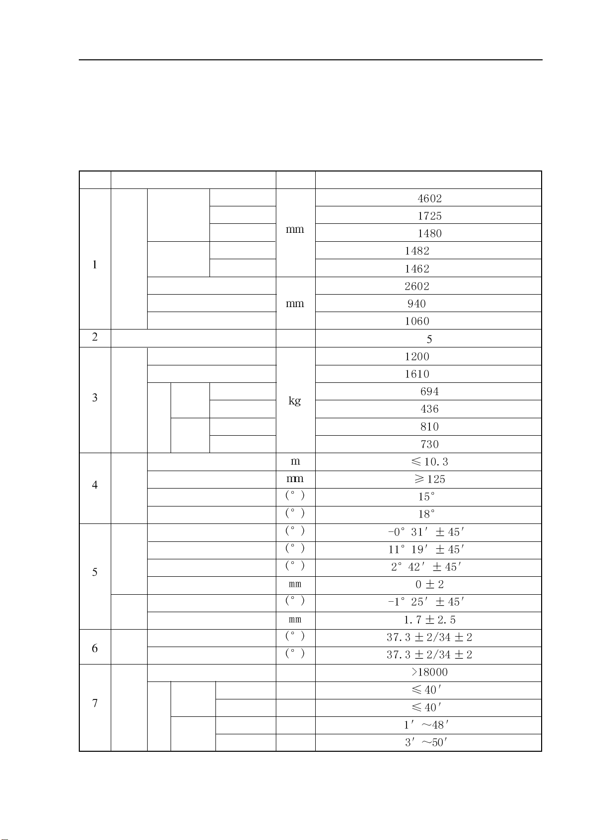
Table 1 Complete vehicle basic parameters
Number
Item name
Length
Overall
dimension
Width
Height
Front wheel
Wheel track
Rear wheel
Wheel base
Front suspension
Dimension parameters
Rear suspension
Passenger number
Complete vehicle herb mass
Max. total mass
No
load
Full
Mass parameters
load
Weight distribution
Front axle
Rear axle
Front axle
Rear axle
Min. turning diameter
Unit
Person
Parameters
±15
±15
±20
±10
±10
±30
±30
Min. gound clearance
Approach angle (full load)
Departure angle (full load)
Traverse ability
Front wheel camber
Kingpin inclination angle
caster angle
parameters
Convergence of front wheels
Front wheel alignment
Rear wheel camber
Convergence of rear wheels
alignment
Rear wheel
parameters
Left wheel: inside/outside
wheel
steering
Right wheel:inside/outside
Front wheel
Head lamp light
Luminous intensity of
high beam of head lamp
Left and
right
inclination
Down
High beam
optical axis
inclination
Candera
Left lamp
Right lamp
Left lamp
Right lamp
1
Page 13
Brief introduction on Geely model “FC” Basic parameters
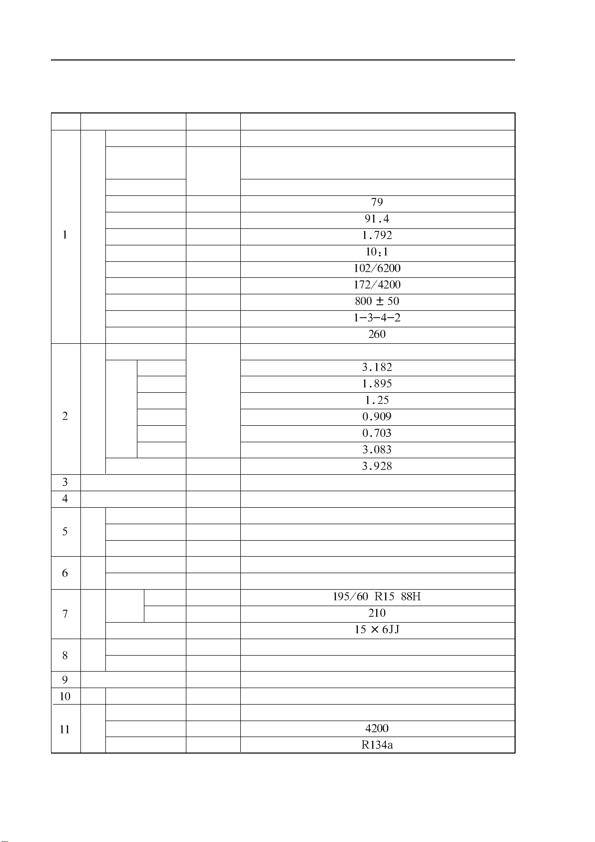
Table 2 Types and parameters of main assembly
Number
Item name
Electric injection system model
Delivery capacity
Engine
Compression ratio
Max. power
Max. torque
Idling speed
Ignition sequence
Min. fuel consumption
Each gear ratio
Transmission
Main gear box ratio
Clutch type
Steering gear
Front brake
system
Braking
Rear brake
Front suspension type
Rear suspension type
Sus-
pension
Radial
Tire
tire
Model
Type
Bore
Stroke
Type
1st gear
nd
gear
2
3rd gear
4th gear
5th gear
Reverse gear
Type
Specification
Air pressure
Unit
//
.//
/
/.
Types and parameters
JL4G18
4-cylinderin-line, four-stroke, water-cooling, double over-head
camshaft, 16-valve, CVVT multipoint injection gasoline engine
United Automotive Electronic Systems Co., Ltd. M7.9.7 electric injection system
5 gears synchronizer of constant mesh gear
Dry single, diaphragm spring, constant pressure
Rack-and-pinion steering gear with hydraulic power
Double pipeline, vacuum boosterwith ABS +EBD anti-lock system
Disc brake
Disc brake
Strut-type front independent suspension
Longitudinal swinging arm and anti-twist beam compound rear suspension
2
axle
Drive
Drive shaft
Body structure
Tail gas
Catalytic converter
Air
Compressor type
condi-
Nominal refrigerating capacity
tioning
system
Refrigerant
Rim
Type
Breakaway
BalI cage and tripot type constant velocity universal joint
Loaded all-metal body
Honeycomb cordierite carrier, noble metal catalyst
Swirl or swash plate compressor
Page 14
Brief introduction on Geely model “FC” Basic parameters
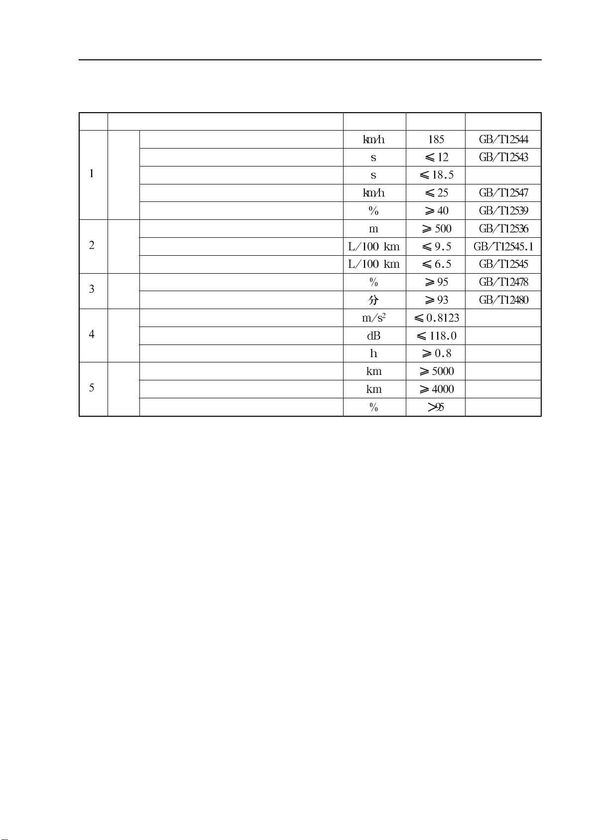
Table 3 Main performance parameters of complete vehicle
Number
Item name
Max. vehicle speed
0-100 km/h accelerating time
Accelerating time from 30km/h to 100km/h at 4th gear
Min. stable vehicle speed at 4th gear
Power performance
Slide Distance (full-load, initial speed 50km/h)
Max. climbing speed
Fuel consumption with 4 operating modes
Economy
Average fuel consumption at specified operating mode
performance
Dust sealing degree
Seal
perfor-
Ride
perfor-
mance
mance
Rain protection seal limit value
Weighted acceleration root of mean square
Equivalent mean value
Reduced comfort boundary
Average mileage to first failure
Average mileage between failures
Reliability
Efficient degree
Unit
Parameters Remarks
3
Page 15
Maintenance period-Regular maintenance items
Maintenance period
Regular maintenance items
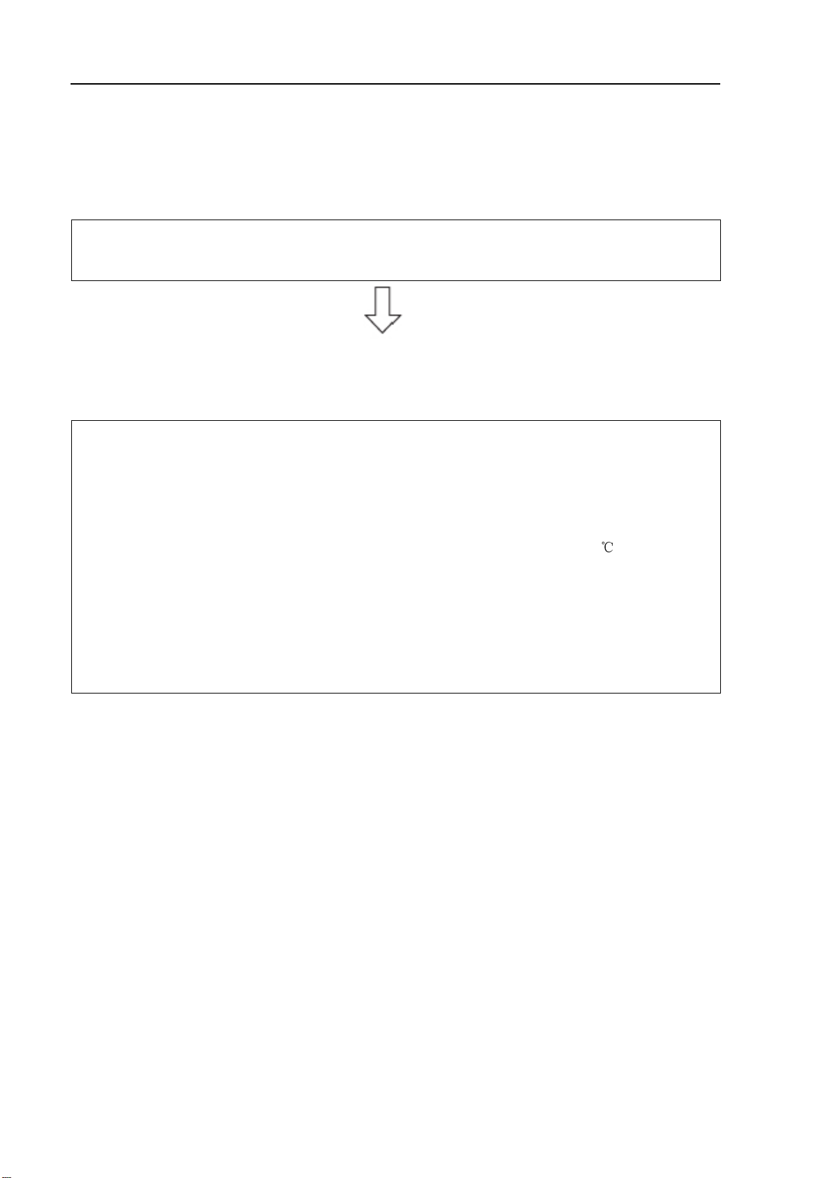
Your precious automobile should be maintained according to maintenance period
at normal conditions (see table on maintenance period at normal conditions)
If your precious automobile is mainly driven under one or more of the following conditions, some
maintenance items must be performed more frequently (see table on maintenance period at severe
conditions).
A. Road conditions
1. Driving on rugged, muddy or melting snow road.
2. Driving on dusty road.
B. Driving conditions
1. Towing tail vehicle, equipped with camp frame or top storage racks.
2. Repeated on short-distance driving within 8 km and the temperature is below 0 .
3. Vehicles driven for long distance under idle speed or low speed over a long period of time,
such as police car, taxi or delivery truck.
4. Continuously driving at high speed for more than 2 hours frequently. (With 80% of max. vehicle speed)
5. Vehicles driven with idle speed or low speed over a long period of time or frequently accelerated or decelerated, such as training car of driving training class.
4
Page 16
Maintenance period-Table on maintenance period at normal conditions
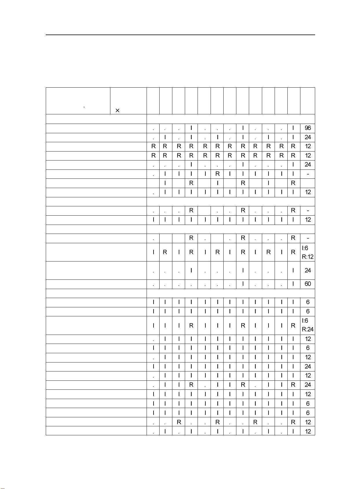
Table on maintenance period at normal conditions
Maintenance content:
I: Inspection and correction or replacement if necessary R: Replacement
Maintenance period
(Odometer readings or
operating months subject to
the first coming)
Engine basic elements
1. V alve clearance*
1
2. Drive belt
3. Engine oil (APLSJ,SL or ILSAC) *
4. Oil filter*
5. Cooling and heating system hose and joint*3*
6. Engine coolant*5*
2
6
7. CVVT oil duct filter screen
8. Exhaust pipe and fixed mount
Ignition system
9. Spark plug
10. Battery
Fuel and exhaust gas control system
11. Fuel filter
mileage
reading
1000km
7. 5 1 5 22.5 30 37.5 45 53.5 60 67.5 7 5 82.5 90
2
4
months
12. Air filter core
Connecting conditions of fuel tank cover,
13.
fuel pipe and fuel evaporation control valve*
7
14. Activated carbon canister
Chassis and vehicle body
15. Brake pedal and parking brake
16. Brake pad and brake disc
17. Brake fluid
18. Brake Pipe and hose
19. Power steering oil
20. Steering wheel, steering linkage and gear box oil
21. Drive shaft dust cover
22. Ball joint and dust cap
23. Transmission oil
24. Front and rear suspension
25. Tire and tire pressure
26. All light, horn, wiper and washer
27. Air conditioner cleaning filter screen
Air conditioning system/ secondary refrigerant
5
Page 17

Maintenance period-Table on maintenance period at normal conditions
Note: *1 Indicating that check valve noise and engine vibration condition, and adjust them if necessary.
*2
It is suggested that see operating modes on page 116 of operating instruction to perform.
*3
Indicating that check once every 20000km or 12 moths after 80000km or 48 months.
*4
Indicating that check water tank and condenser are blocked by leaves, dust or insects, and clean
hose connections.
*5
Replace at initial 60000km, and replace every 30000km in future.
*6
Only “Geely genuine ultra-long engine coolant” or equivalent high-quality ethylene glycol engine
coolant without silicate, amines, nitrite, borate and with long-life compound organic acid technology
are allowed to use, and coolant should be repeated several times until it is filled up.
*7
Indicating that check once every 20000km or 12 moths after 80000km or 48 months.
6
Page 18
Maintenance period-Table on maintenance period at severe conditions
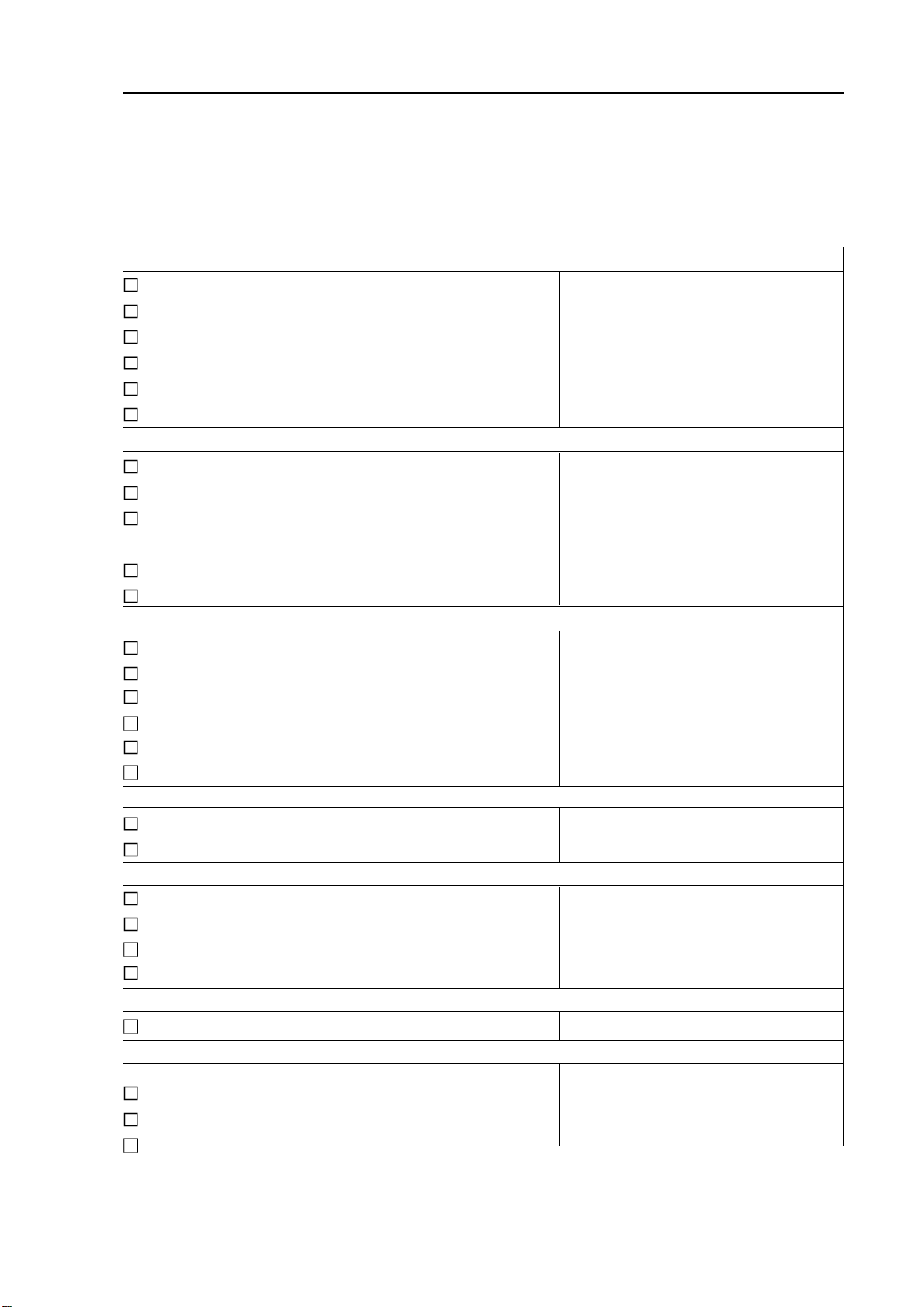
Table on maintenance period at severe conditions
According to the driving conditions listed below, maintenance should be performed to the items that
should be maintained more frequently (for other items not listed, please see Table on maintenance
period at normal conditions)
A-1: Driving on rugged, muddy or melting snow road
Inspection of brake pad and brake disc Every 5,000 km or 3 moths
Inspection of brake pipeline and hose Every 10,000 km or 6 moths
Inspection of ball joint and dust cover Every 10,000 km or 6 moths
Inspection of drive shaft dust cover Every 10,000 km or 12 moths
Inspection of the steering wheel, steering linkage and gear box oil
Check of front and rear suspension Every 10,000 km or 6 moths
A-2: Driving on dusty road
Replacement of engine oil Every 5,000 km or 6 moths
Replacement of engine oil filter Every 5,000 km or 6 moths
Inspection or replacement of air filter core I: Every 2,500 km or 3 moths
Inspection of brake block and brake disc Every 5,000 km or 3 moths
Replacement of air conditioner cleaning filter screen Every 15,000 km
B-1: Towing tail vehicle, equipped with camp frame or top storage racks
Every 5,000 km or 3 moths
R: Every 10,000 km or 6 moths
Replacement of engine oil Every 5,000 km or 6 moths
Replacement of engine oil filter Every 5,000 km or 6 moths
Inspection of brake pad and brake disc Every 5,000 km or 3 moths
Inspection or replacement of transmission oil Every 60,000 km or 24 moths
Inspection of front and rear suspension Every 10,000 km or 6 moths
Screwing down the bolts and nuts of the chassis and vehicle body
Every 10,000 km or 6 moths
B-2: Repeated on short-distance driving within 8 km and the temperature is below 0 °C
Replacement of engine oil Every 5,000 km or 6 moths
Replacement of engine oil filter Every 5,000 km or 6 moths
Vehicles driven for long distance under idle speed or low speed over a long period of time, such as police car, taxi or delive rytruck
B-3:
.
Replacement of engine oil Every 5,000 km or 6 moths
Replacement of engine oil filter Every 5,000 km or 6 moths
Inspection of PCV valve and pipelines Every 5,000 km or 6 moths
Inspection of brake block and brake disc Every 5,000 km or 3 moths
Continuously driving at high speed for more than 2 hours frequently (With 80% of max. vehicle speed)
B-4:
Replacement of transmission oil Every 40,000 km or 12 moths
Vehicles driven with idle speed or low speed over a long period of time or frequently accelerated or
B-5:
decelerated, such as student car of driving training class.
Replacement of engine oil Every 3,000 km or 3 moths
Replacement of engine oil filter Every 3,000 km or 3 moths
Inspection of PCV valve and pipelines Every 3,000 km or 3 moths
7
Page 19
Engine control system·- EFI system
Engine control system
EFI system
On-vehicle inspection
1. Inspection of the voltage of power steering oil pres-
sure sensor
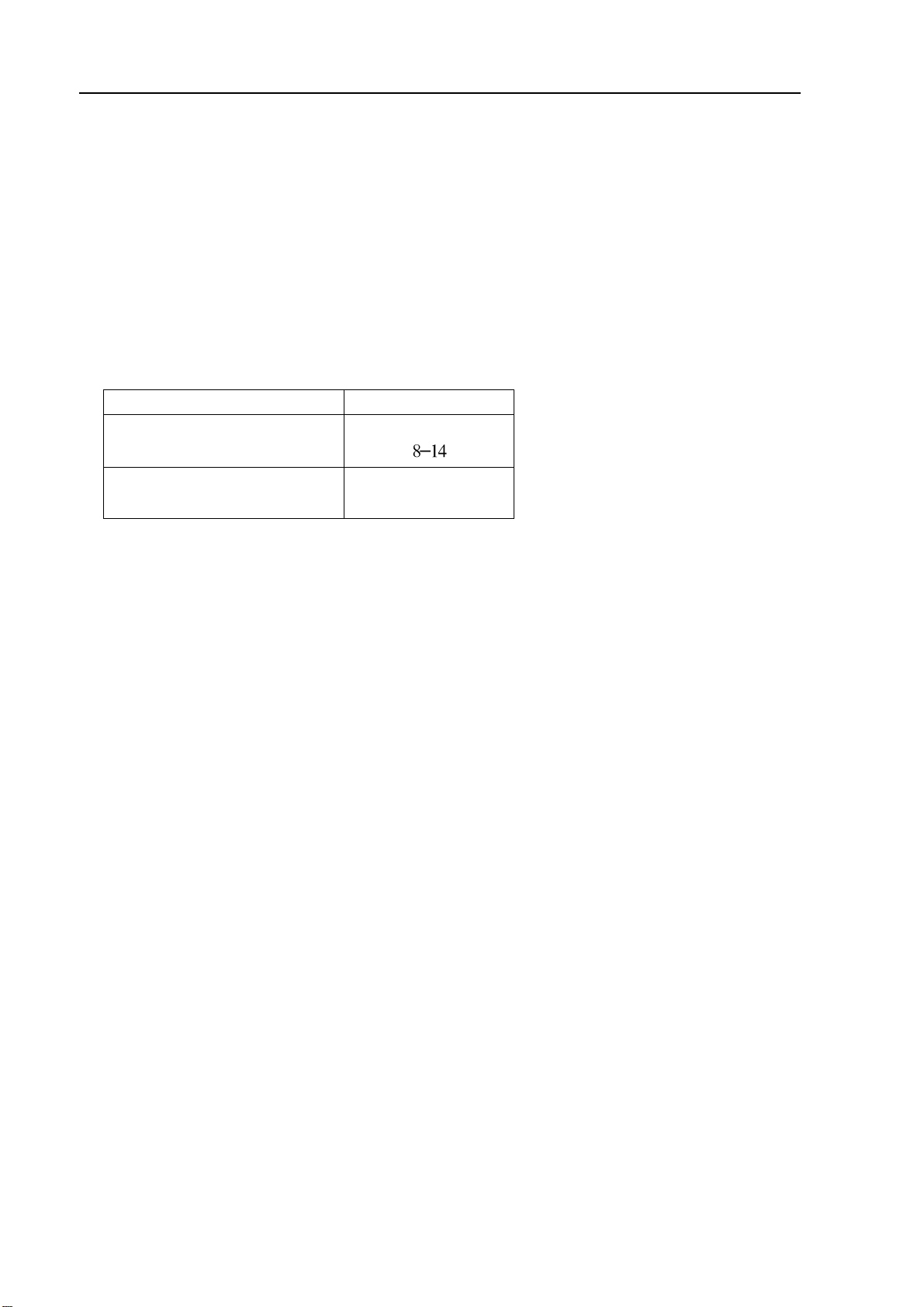
Measure the voltage between PS terminal and E2 terminal
with ohmmeter
Conditions Voltage (V)
Not turning steering wheel with
engine at idle speed
Turning steering wheel with
engine at idle speed
2. Inspection of stepping motor
(a) With engine running at idle speed, pull out the connection harness of stepping motor, and the change
of engine rotating speed indicates that the stepping motor operates normally.
(b)Pull out the connection harness of stepping motor, and measure the terminal current with universal
meter. When engine is running, there being impulse current output at the terminal indicates that there
is no trouble with ECU and stepping motor control system, and if idling is not stable at the moment
and deviates greatly from specified value, the stepping motor should be replaced. If there is no
impulse current output at the terminal, turn on air conditioner to test again, and still no impulse
current output indicates that there is trouble with ECU and stepping motor control system circuit.
(c) Check the malfunction of stepping motor circuit with diagnostic instrument.
0-1.5
8
Page 20
Engine control system·- EFI system
Inspection
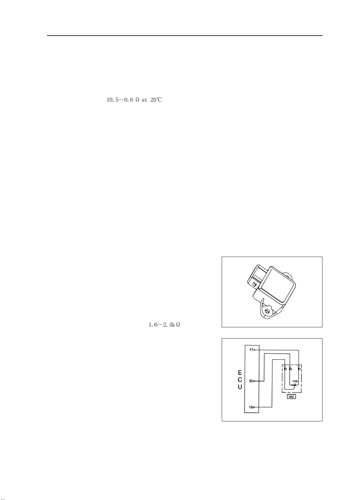
1. VVT control solenoid valve assembly (4G18-1006200)
(a)Resistance inspection
(1)Measure the resistance between terminals with ohmmeter
Resistance:
(b)Operation inspection
Connect battery positive (+) wire to No.1 terminal and negative (-) wire to No. 2 terminal, and check
valve operation.
Note: ensure that the valve is not stuck.
Hint: if there are foreign matters in the valve, the valve could not be closed tightly and will
thus result in slight pressure being lifted toward higher direction.
2. Throttle body components (4G18-1001240)
(a)Inspection of throttle body
(1)Throttle valve shaft should not swing.
(2)All channels should not be blocked.
(3)Throttle valve plate should rotate flexibly and act smoothly.
(4) When the throttle is at closed position, there should be no clearance between throttle stop bolts and
throttle lever.
Note: it is not allowed to adjust the throttle stop bolts.
3. Throttle position sensor (4G18-3600080)
(a)Resistance inspection
(1)Remove the wiring harness connectors of throttle posi-
tion sensor.
(2)Measure the resistance between 1# pin and 2# pin with
ohmmeter, resistance value: .
(3)Connect 2 terminals respectively to 1# pin and 3# pin,
and turn the throttle, the resistance value varies linearly
with the opening of throttle, but 2# pin and 3# pin are
contrary to this.
Note: pay attention whether there is great jump with
resistance value when observing resistance change.
9
Page 21
Engine control system·- EFI system
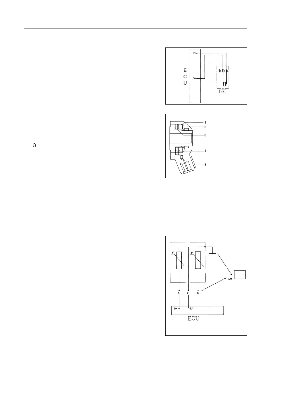
4. Knock sensor (4G18-3600020)
Measuring method:
(Removing the joint) place digital universal meter at ohm gear,
and connect 2 terminals respectively to 1# pin and 2# pin, and
the resistance under normal temperature should be more than
1M . Place digital universal meter at millivolt gear, and knock
around knock sensor with a hand hammer, there should be voltage
signal output at the moment.
1 Vibration block
2 Housing
3 Piezoelectric ceramics
4 Contact
5 Electric connection
5. Water temperature sensor (4G18-3600040)
This sensor applies sealing NTC thermal resistor in temperature sensor, and resistance value varies with
ambient temperature, thus slight change of outside temperature could be measured. Measuring its output resistance could reflect the temperature of contact media. Signals from A and C are sent to ECU,
and Signals from B and earth are sent to instrument.
Operating principle (Fig. 1):
Fig. 1
Note: A, B and C represent 3 pins of sensor, and see pin root for the mark.
10
Page 22
Engine control system·- EFI system
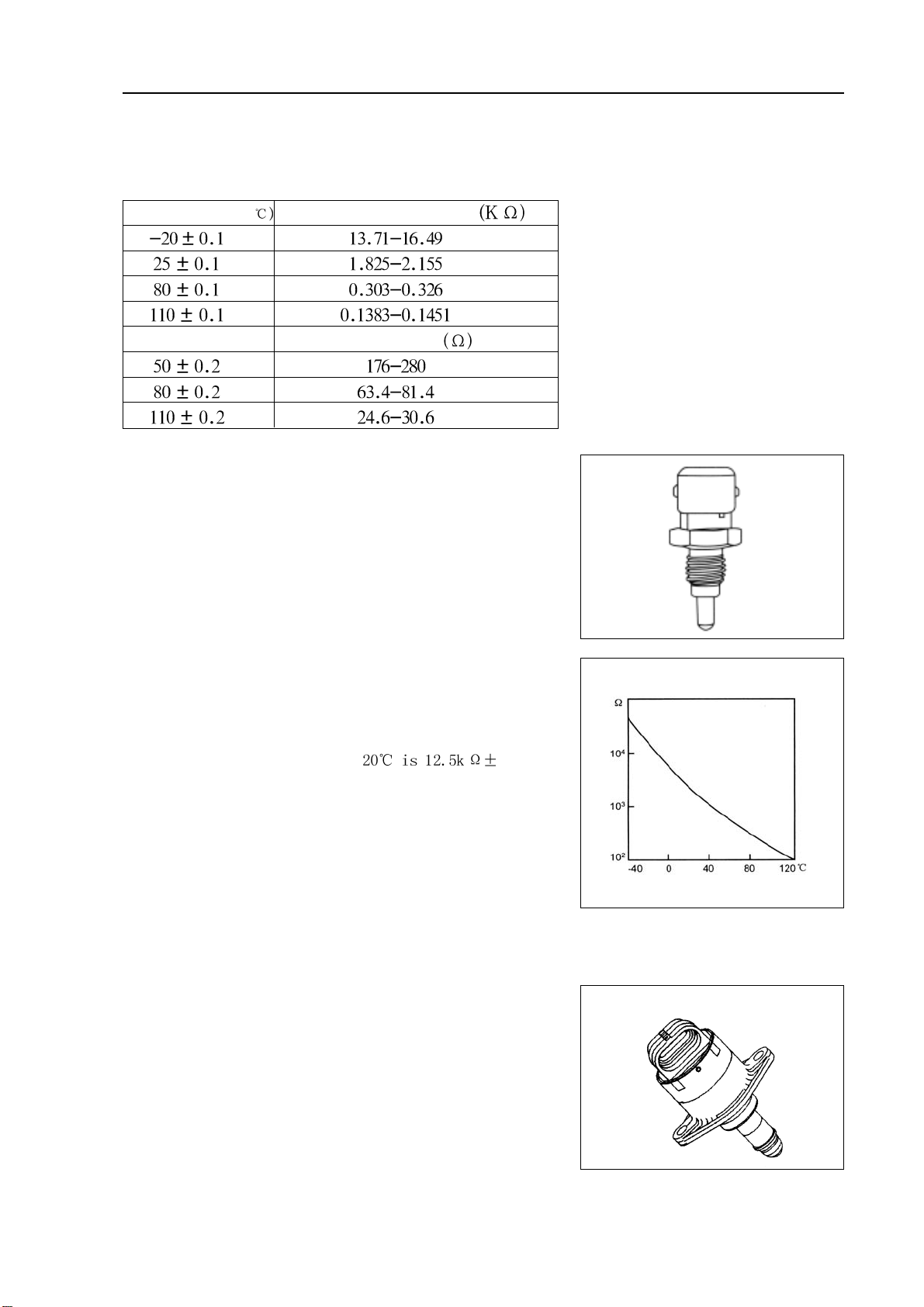
Use digital universal meter to measure:
Resistance-temperature characteristics of temperature sensor
Temperature range(
Resistance at A and C
Resistance at B
6. Intake air temperature sensor (4G18-3600090)
Intake air temperature sensor is a resistor with negative temperature coefficient (NTC), resistance varies with intake air
temperature, and this sensor sends a voltage indicating change
of intake air temperature to controller.
Simple measuring method:
(Removing the joint) place digital universal meter at ohm gear,
and connect 2 terminals respectively to 1# pin and 2# pin of
sensor, and rated resistance at 5%, and
other corresponding resistance values could be measured according to the characteristic curve in above drawing. Analog
method could also be applied in measurement. Use an electric blower to blow air into the sensor (pay attention not to
keep them too near), and observe the change of resistance,
which should decrease at the moment.
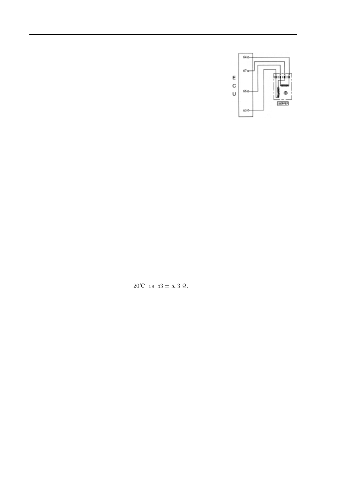
7. Stepping motor (4G18-3600070)
Schematic diagram and pins
Characteristic curve of
temperature sensor
Characteristic curve of intake air
temperature sensor NTC resistor
Stepping motor of idle speed actuator
11
Page 23
Engine control system·- EFI system
Electrical
Pins: Pin A is connected to ECU No. 65 pin
Pin B is connected to ECU No. 66 pin
Pin C is connected to ECU No. 67 pin
Pin D is connected to ECU No. 64 pin
wiring
diagram
on stepping motor
of idle
speed
actuator
Maintenance precautions:
1. It is not allowed to apply any force at axial direction with the purpose of pressing into or pulling out the
axle;
2. Before idle speed regulator with stepping motor is mounted into throttle body, its shaft must be at fully
retractive position;
3. Pay attention to clean and maintain bypass air passage frequently;
4. After removing battery or ECU, pay attention to self-teach stepping motor in time.
Self-teach method of M7 system: turn on ignition switch but not start engine immediately, and start it
after 5 seconds. If engine idle speed is found bad at the moment, it is
necessary to repeat the above steps.
Simple measuring method: (removing the joint) place digital universal meter at ohm gear, and connect
2 terminals respectively to Ad pin and BC pin of regulator, and rated resistance at
12
Page 24
Engine control system·- Throttle body assembly
Throttle body assembly
Removing, installing and disassembling, assembling
1. Discharge coolant (see Page 73).
2. Remove air cleaner hose assembly.
3. Remove engine plastic hood components [4G18-1000310].
4. Remove throttle pull cable assembly.
5. remove throttle body assembly [4G18-1008240].
(a ) Uncouple throttle position sensor joint and stepping motor joint.
(b)Disassemble ventilation hose.
(c) Remove 2 bolts and throttle control pull cable bracket.
(d)Remove 2 preheating water inlet and outlet hoses of throttle.
(e)Remove 2 bolts and 2 nuts, and remove throttle body from intake air manifold.
6. Remove stepping motor of throttle body [4G18-3600070].
Remove 3 screws and stepping motor.
7. Install stepping motor of throttle body.
Install stepping motor.
8. Install throttle body assembly.
(a)Install new seal gasket on intake air manifold.
(b)Install throttle body, 2 bolts and 2 nuts.
Torque:
9. Refill coolant.
10.Check there is leakage with coolant.
13
Page 25
Fuel-Fuel system
Fuel
Fuel system
Precautions
1. Before repairing fuel system, uncouple battery negative (-) wire at first.
2. When operating on fuel system, do not smoke or repair near fire area.
3. Do not let gasoline come into contact with rubber or leather parts.
4. Take measures to prevent gasoline leaking.
(a)Uncouple electric fuel pump joint.
(b)Start engine and turn ignition switch to LOCK position
after the engine flames out.
(c) Uncouple battery negative (-) wire.
(d)Couple electric fuel pump joint.
5. Fuel system
(a ) There will be a great amount of gasoline flowing out
when disassembling high-pressure fuel pipe,
therefore, it is required to observe the following
procedures.
(1 ) T ake measures to prevent gasoline leaking.
(2 ) Disassemble fuel pipe.
(3 ) Completely discharge the oil in fuel pipe.
(4 ) Cover the fuel pipe with plastic bag to avoid pipe
damage and foreign matters entering.
(5 ) Place a container under the joint.
(b)When removing and installing injection nozzle, always
observe the following precautions.
14
Page 26
Fuel-Fuel system
(1)It is not allowed to use o-ring repeatedly.
(2)When installing o-ring, always be careful to avoid dam-
aging o-ring.
(3) Before installing, coat o-ring with spindle oil or gasoline.
It is not allowed to coat with engine oil, gear oil or
brake fluid.
(c) As shown in the diagram, install injection nozzle to oil feed
pipe and cylinder head.
Before installing, ensure that spindle oil and gasoline are
coated at the contact position between o-ring and oil feed
pipe.
injection nozzle
o-ring
oil feed pipe
Correct
Wrong
oil feed pipe
o-ring
washer
(d) When disassembling oil feed pipe, always observe the fol-
lowing precautions.
(1)Remove oil feed pipe clips.
(2)Remove oil feed hose.
(3)Cover oil inlet of fuel distribution pipe with plastic bag
to avoid foreign materials entering the fuel distribution
pipe.
6. Inspection of fuel leakage
(1)After completing maintenance, check there is leakage with the whole fuel system.
(2)Connect hand-held tester to diagnostic joint.
(3)Turn ignition switch to ON and turn main switch of hand-held tester to ON.
(4)Switch hand-held tester to function test state.
(5)For further details, please see hand-held tester operating instruction.
(6)If there is no hand-held tester, connect battery anode and cathode to electric fuel pump joint.
(7)Ensure that there is no leakage with all parts of electric fuel pump.
(8)Turn ignition switch to LOCK.
(9)Disassemble hand-held tester from diagnostic interface joint.
15
Page 27
Fuel-Fuel system
On-vehicle inspection
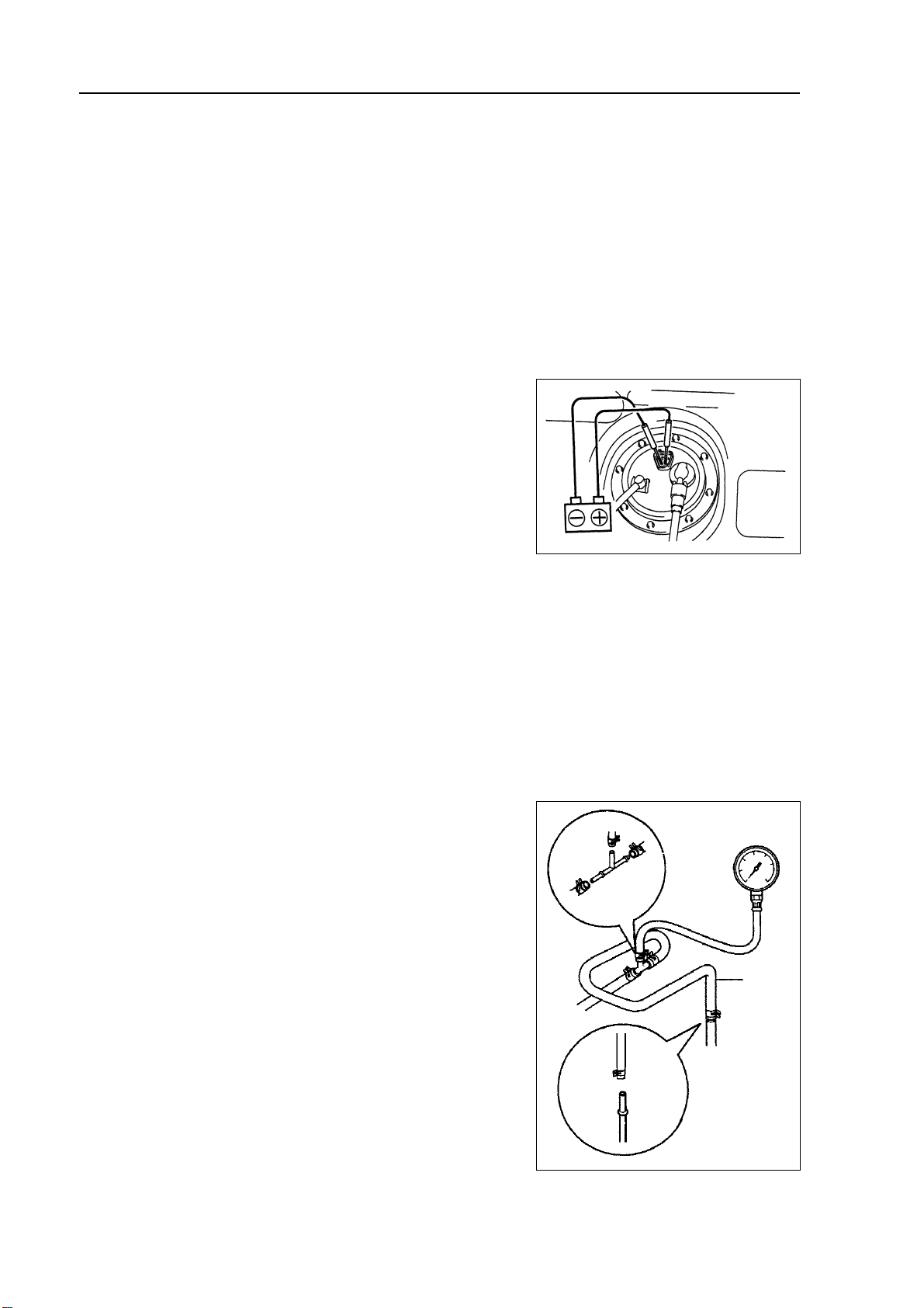
1. Inspection of fuel pump function
(a)Connect hand-held tester to diagnostic joint.
(b)Turn ignition switch to ON and turn main switch of hand-
held tester to ON.
Note: do not start the engine.
(c) Switch hand-held tester to function test state.
(d)For further details, please see hand-held tester operating
instruction.
(e)If there is no hand-held tester, connect battery positive (+)
wire to P+ terminal and negative (-) wire to P- terminal.
2. Inspection of fuel pressure
(a)Preparation of inspection.
Purchase new fuel hose and take out fuel pipe joint.
(b)Take measures to prevent gasoline leaking.
(c) Disassemble fuel pipe clamp at fuel pipe joint of fuel rail
component.
(d) Disassemble fuel hose from fuel pipe of fuel rail component.
(e)As shown in the diagram, install special tool (pressure
gauge) with special tool and fuel pipe joint.
(f) Check there is fuel leakage.
(g)Start engine.
(h)Measure the fuel pressure at idle speed state.
Fuel pressure: 390~400Pa
(i) Take measures again to prevent gasoline leaking.
(j) After measuring the fuel pressure, remove special tool.
(k) Connect back fuel hose.
(l) Install fuel hose fixing clip to fuel pipe joint.
(m)Check there is fuel leakage.
16
Special
tool
Page 28
Fuel-Fuel system
Inspection
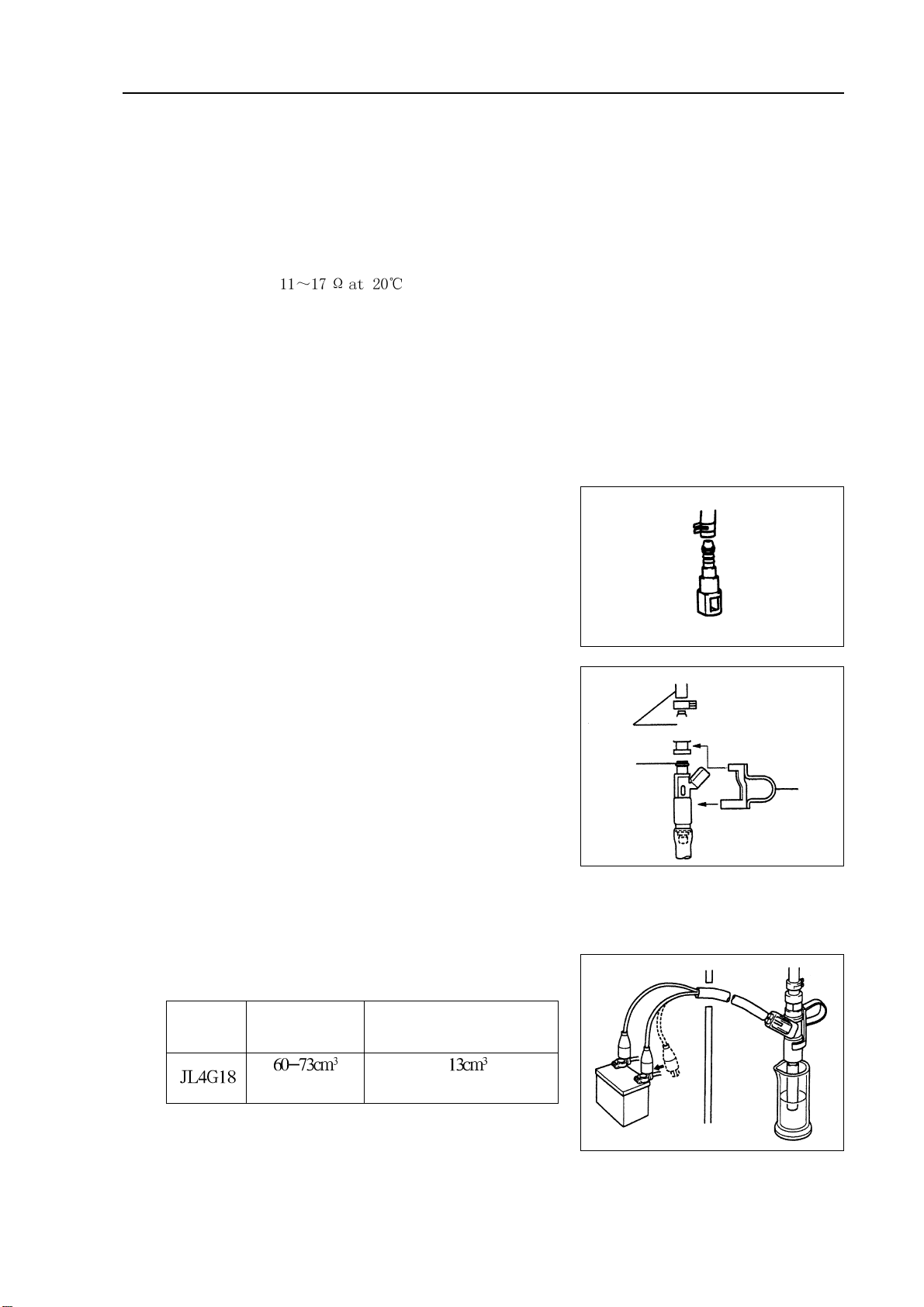
1. Fuel injector components [4G18-1112120]
(a)Check injection nozzle resistance.
(1) Measure the resistance between terminals with
ohmmeter.
Resistance:
Hint: if resistance is not within specification, replace injection nozzle.
(b)Injection nozzle test.
Warning: there should be no sparks during testing.
(1 ) Purchase new fuel pipe and take out fuel hose joint.
(2 ) Install special tool and fuel hose joint to fuel pipe.
Note: Only after performing precautions could the
connection operation of fuel hose joint (fastjoint mode) be allowed to perform.
Warning: before connecting fuel pipe joint (fast-joint
mode), please read precautions carefully
(3)Install o-ring to injection nozzle.
(4) Connect special tool (joint and hose) to injection nozzle,
and hold down the injection nozzle to prevent fuel splash.
(5 ) Place injection nozzle into measuring cup.
Hint: install proper hose on injection nozzle to prevent
gasoline injecting out of the cup.
(6)Connect special tool to injection nozzle joint.
(7)Connect special tool to battery for 15 seconds, and measure the injection volume with measuring
cup, each injection nozzle should be test for 2~3 times.
Injection volume:
Engine Injection volume Uneven volume between
each injection nozzle
Every 15 seconds
Hint: if injection volume is not within specification, replace
injection nozzle.
or less
Special
tool
o-ring
Special
tool
17
Page 29
Fuel-Injection nozzle assembly
Injection nozzle assembly
Replacement
1. Take measures to prevent gasoline leaking.
2. Remove engine plastic hood components.
3. Uncouple engine wire harness [4G18-3724100].
(a)Remove injection nozzle joint.
(b)Remove exhaust gas hose.
4. Remove fuel pipe assembly
(a)Loosen oil feed hose clips.
(b)Pull oil feed hose away from fuse distribution pipe.
Notes:
z
Check there is dirt on fuel pipe and its joint before removing, and clean it off in the case of dirt.
z
It is only allowed to remove with hands.
z
Check there are foreign matters with the removed fuel pipe seal surface, and clean them off in the
case of foreign matters.
z
Cover the fuel pipe with plastic bag to avoid pipe damage and foreign matters entering.
5. Remove fuel pipe assembly
Remove 2 bolts and oil feed pipe (together with injection nozzle).
6. Remove injection nozzle components.
Pull out 4 injection nozzles from oil feed pipe.
7. Install injection nozzle components.
Coat a thin layer of gasoline on o-ring and rotate left and right to push injection nozzle into oil feed pipe.
Notes:
z Be careful not to rotate o-ring.
z Check injection nozzle could rotate smoothly after it is installed, and if not replace with new o-ring.
8. Install fuel hose assembly.
Install fuel hose to oil feed pipe.
Notes:
z Check there are damage or foreign matters in the binding site of fuel pipe.
z After installing, pull the fuel pump with hands to check the fuel pipe is bound firmly with joint.
18
Page 30

Fuel-Injection nozzle assembly
9. Install fuel rail component [4G18-1112110].
(a)Check injection nozzle o-ring and replace if there is damage.
(b)Install isolator on cylinder head.
(c) Install fuel rail component together with injection nozzle.
Torque:
(d ) Install fuel pipe fixing clip.
Torque: m
10. Check the function of electric fuel pump and check there is fuel leakage.
19
Page 31

Fuel - Fuel pump assembly
Fuel pump assembly
Removing, installing and disassembling, assembling
1. Take measures to prevent gasoline leaking
2. Remove rear seat cushion assembly
3. Remove rear floor repairing hole cover
4. Remove No. 2 fuel evaporation assembly
Notes:
z Check there is contaminant looked like dirt around the joint before operating and clean it off in the
case of contaminant.
z Be careful of the contaminant looked like dirt, because fast-joint depends on o-ring to seal fuel pipe
and joint.
z Do not perform this operation with tools.
z Do not bend or distort nylon hose.
z Cover the joint with plastic bag after removing the fuel hose.
z When the joint is stuck with fuel pipe, clip the hose with fingers and rotate carefully to release the
hose, and then remove it.
5. Remove fuel tank main fuel hose and oil return pipe assembly
Notes:
z Check there is contaminant looked like dirt around the joint before operating and clean it off in the
case of contaminant.
z Be careful of the contaminant looked like dirt, because fast-joint depends on o-ring to seal fuel pipe
and joint.
z Do not perform this operation with tools.
z Do not bend or distort nylon hose.
z Cover the joint with plastic bag after removing the fuel hose.
z When the joint is stuck with fuel pipe, clip the hose with fingers and rotate carefully to release the
hose, and then remove it.
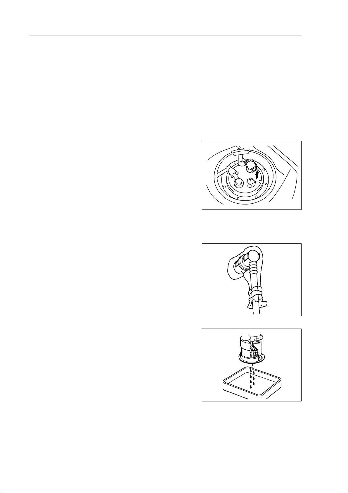
6. Remove fuel pump assembly
(a ) Screw off fuel pump tighten nut (plastic fuel tank) or remove
6 screws (iron fuel tank).
(b)Pull out fuel pump assembly.
Notes:
z Do not damage fuel pump filter screen.
z Be careful not to bend the measuring oil arm of fuel gauge
float unit.
7. Install fuel pump assembly
Torque: 8 N.m
8. Install rear floor repairing hole cover
Install rear floor repairing hole cover with butyl rubber cloth.
9. Check there is fuel leakage.
20
Page 32

Fuel - Fuel tank assembly
Fuel tank assembly
Removing, installing and disassembling, assembling
1. Take measures to prevent gasoline leaking
(see Page 14)
2. Remove rear seat cushion assembly
3. Remove rear floor repairing hole cover
4. Remove No. 2 fuel evaporation assembly
5. Remove fuel tank main fuel hose and oil return pipe
assembly
6. Remove fuel pump assembly
7. Discharge fuel
8. Remove front floor bracket
9. Remove front exhaust pipe assembly
(a)Move away carpet and remove oxygen sensor joint.
(b)Remove front exhaust pipe assembly
10.Disassemble the vent pipe of fuel hose
11.Disassemble filler pipe from fuel tank
12.Remove No. 2 fuel evaporator hose assembly
Press fuel hose joint and then pull out the hose.
Notes:
Check there is contaminant that looked like dirt around the
joint before operating and clean it off in the case of
contaminant.
Be careful of the contaminant that looked like dirt, because
fast-joint depends on o-ring to seal fuel pipe and joint.
Do not perform this operation with tools.
Do not bend or distort nylon hose.
Cover the joint with plastic bag after removing the fuel hose.
When the joint is stuck with fuel pipe, clip the hose with
fingers and rotate carefully to release the hose, and then
remove it.
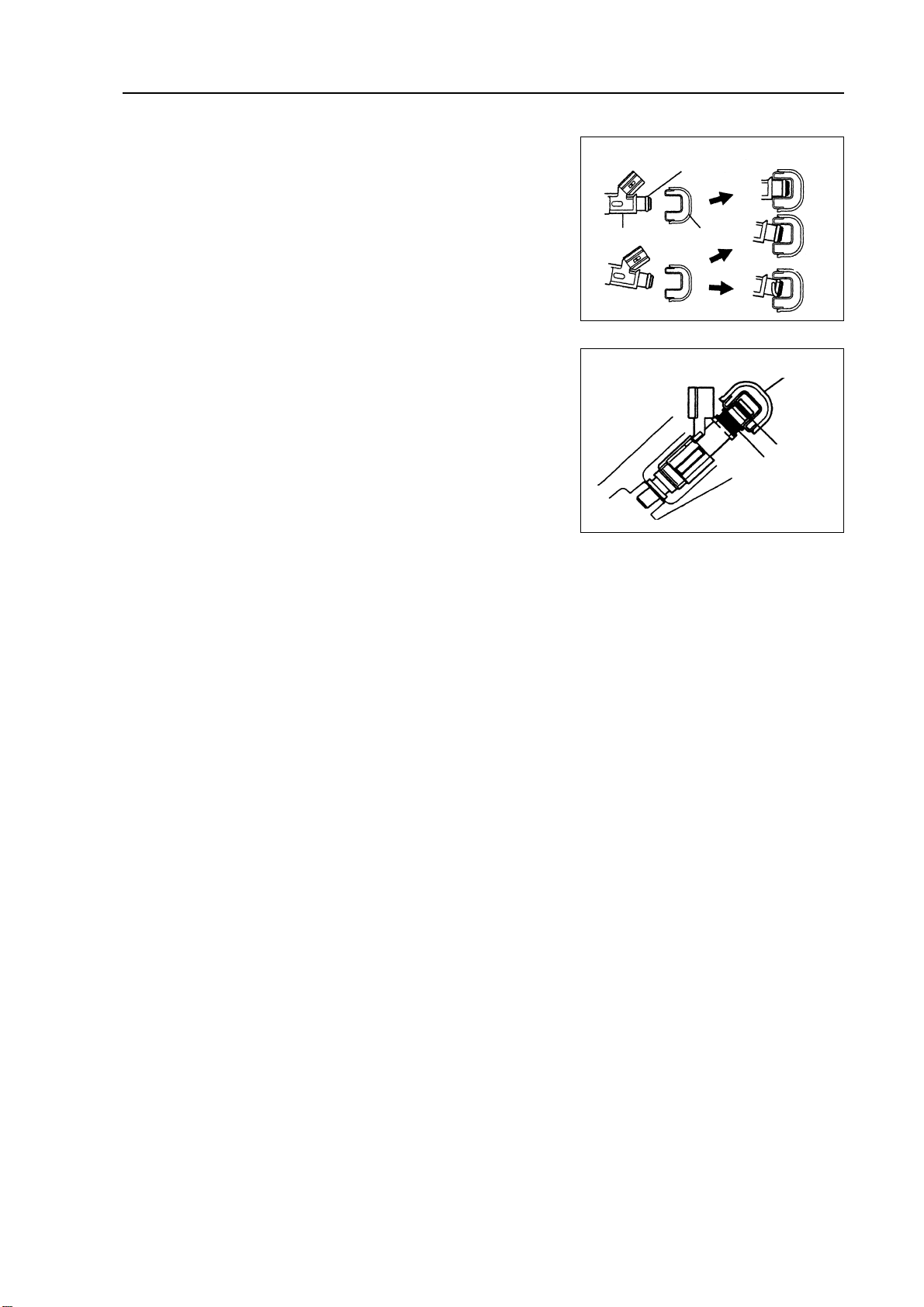
13.Disassemble fuel tank main fuel hose assembly
Clip the protrusion part of fixing ring and move lock claw toward
open direction, and then pull out the hose as shown in the
diagram.
Notes:
Check there is contaminant looked like dirt around the joint
before operating and clean it off in the case of contaminant.
Nylon pipe
Fuel pipe clip
O-ring
Pipe
21
Page 33

Fuel - Fuel tank assembly
Be careful of the contaminant that looked like dirt, because
fast-joint depends on o-ring to seal fuel pipe and joint.
Do not perform this operation with tools.
Do not bend or distort nylon hose.
Cover the joint with plastic bag after removing the fuel hose.
When the joint is stuck with fuel pipe, clip the hose with
fingers and rotate carefully to release the hose, and then
remove it.
14. Remove fuel tank assembly
(a ) Remove parking brake pull cable retaining clip.
(b)Place jack under fuel tank. Remove fuel tank band harness and fuel
tank assembly.
15. Remove fuel tank main fuel hose and oil return pipe
assembly
16. Remove No. 2 fuel evaporation hose assembly
17. Remove No. 1 fuel tank gasket
18. Remove No. 1 fuel tank protector
Remove rivet with electric drill and then remove fuel tank protector.
19. Install No. 1 fuel tank protector
Install fuel tank protector with rivet.
20. Install No. 1 fuel tank gasket
As shown in the diagram, install new fuel tank gasket.
21. Install fuel tank assembly
Torque: 39 N.m
22. Install front exhaust pipe assembly
Torque: 40 N.m
23. Install front floor bracket
Torque: 30 N.m
24. Install rear floor repairing hole cover
Install rear floor service hole cover with butyl rubber cloth.
25. Check fuel leakage (see Page 14)
26. Check gas leakage of exhaust system
22
Page 34

Exhaust gas control - Exhaust gas control system
Exhaust gas control
Exhaust gas control system
On-vehicle inspection
1. Check oxygen sensor.
(a)Let the engine run at idle speed for 3 minutes to ensure oxygen sensor reaches operating tempera-
ture of 350
(b)Place digital universal meter at DC voltage gear, and connect 2 terminals respectively to (gray) pin
and (black) pin of sensor, and voltage should fluctuate
quickly between 0.1-0.9V at the moment.
Warning:
Perform inspection immediately after warming
up vehicle.
If voltage change could not be confirmed,
it is necessary to heat oxygen sensor again.
2. Check rotating speed after fuel cut off.
(a)Accelerate engine at least to 3500rpm.
(b)Check the operating noise of injection nozzle with listening device.
(c) When throttle is released, check the operating noise of injection nozzle recovers after stop.
3. Check fuel evaporation exhaust control system.
(a)Check the pipe clamps of connecting pipeline between
charcoal canister and carbon canister solenoid valve are
firmly clipped and check there is leakage.
(b)Check there is trouble with fuel evaporation exhaust con-
trol system with failure diagnostic instrument.
4. Visually check hose, joint and hot fin.
Check cracks, leakage and damage.
Hint: the disconnecting of engine oil level gauge, oil opening
cover and PCV hose may cause running failure of engine.
The cracks, looseness and not connecting at the intake
system between throttle and cylinder head will result in
redundant air entering and running failure of engine.
23
Page 35

Exhaust gas control - Exhaust gas control system
5. Check heater resistance of heated oxygen sensor.
(a)Uncouple oxygen sensor joint.
(b) Place digital universal meter at ohm gear, and connect 2 terminals respectively to 1# (white) pin and
2# (black) pin, and the resistance under normal temperature is 1 6
Oxygen sensor
Main relay
6. Check fuel tank cover.
Visually check fuel tank cover and gasket are distorted or damaged.
24
Page 36

Exhaust gas control - Exhaust gas control system
Inspection
1. Carbon canister assembly [4G18-1129020]
Carbonl canister assembly. Check the function of carbon canister according to the following tables.
Standard:
Inspection Methods Standard
Close B hole and C hole and then
supply vacuum to A hole No leakage
Close C hole and then supply vacuum Air flown out
to A hole from B hole
Close C hole and then blow air Air flown out
into A hole from B hole
Blow air into A hole Air flown out from B hole
and C hole
2. Carbon canister control valve
(a ) For carbon canister control valve, check the conduction be-
tween terminals.
Resistance:
(b)Check the control valve operates.
(1) Supply battery voltage to its terminal.
(2) Check air is flown as the arrow direction on valve body.
3. PCV valve assembly [4G18-1014110]
(a)Blow air into valve from cylinder side and check the air is
easy to get through.
Warning: do not suck against the valve, because the
gasoline left in the valve will make you be
injured.
(b)Blow air into valve from intake manifold side and check
the air is hard to get through.
Hint: if the function does not conform to the standard, PCV
valve should be replaced.
Cylinder side
Clean hose
Intake manifold side
25
Page 37

Engine mechanism - Engine assembly
Engine mechanism
Engine assembly
Inspection
1. Check coolant.
2. Check engine oil.
3. Check battery.
4. Check air filter assembly.
5. Check spark plug [4G18-3705113].
6. Check drive belt [4G18-1307107].
Hint: do not check belt tension, because automatic tensioner is applied.
7. Check ignition timing.
(a)Warm up engine.
(b)Connect timing lamp to engine.
(c) Check ignition timing at idle speed.
Ignition timing: before top dead center
Note: when checking ignition timing, place
transmission at neutral position.
Hint: After run the engine for 5 seconds with rotating
speed of 1000-1300rpm, check the engine could
recover to idle running.
8. Check engine idle speed.
(a)Warm up engine and run it at idle speed.
(b)Read engine rotating number in data flow with diagnostic instrument.
(c) Check idle speed.
Idle speed: about 750-850rpm
Notes:
When checking idle speed, place cooling fan at OFF position.
Turn off all auxiliary devices and air conditioner.
K-line
26
Page 38

Engine mechanism - Engine assembly
9. Check compression pressure.
(a)Warm up engine.
(b)Remove ignition coil.
(c) Remove spark plug.
(d)Check cylinder compression pressure.
(1)Install cylinder compression pressure gauge on spark plug hole.
(2 ) Wide open throttle.
(3)Measure the pressure during crankshaft rotating.
Notes:
Ensure to use fully charged battery to make the rotating speed of engine reach or exceed 250rpm.
When measuring other items, please repeat steps (1) to (3).
Finish the measurement as soon as possible.
Compression pressure: 1080kPa
Min pressure: 1000kPa
Difference among cylinders: 100kPa
(4) If the compression pressure of one or more cylinders is too low, inject a small amount of engine oil
from spark plug hole into the cylinder with low pressure, and repeat steps (1) to (3) to check
pressure.
If the pressure increases after engine oil is injected, the piston ring of this cylinder or the
cylinder has been worn or scratched.
If the pressure is still too low, the valve may be stuck or not fully closed, or the cylinder head
gasket leaks.
10. Check CO/HC.
(a)Start engine.
(b)Keep the rotating speed of engine at 2500rpm for about 180 seconds.
(c) When the engine is idle running, insert the test bar of CO/HC gauge into exhaust pipe at least 40cm.
(d)Immediately check idle speed and CO/HC concentration at 2500rpm.
Hints:
Finish test within 3 minutes.
Perform the test under 2 analog states (idle speed and 2500rpm) according to measuring methods and sequences specified by Emission Regulations.
(e)If CO/HC concentration is not within specified value, perform trouble shooting according to the
following sequences.
(1)Check the function of oxygen sensor.
(2)See possible failure causes listed in the table below, and repair and correct if necessary.
27
Page 39

Engine mechanism - Engine assembly
CO HC Trouble occurrence Possible causes
1. Ignition system malfunction
Ignition timing incorrect
Normal High Unstable idle speed
Low High Unstable idle speed
(HC readings not stable)
Spark plug too dirty, short circuit or clearance
incorrect
2. Valve clearance incorrect
3. Air inlet and exhaust valve leaky
4. Cylinder leaky
1. Vacuum leak:
PCV hose
Intake manifold
Throttle body
Idle speed stepping motor
Vacuum booster and pipelines
2. Fire caused by too thin mixing ratio
1. Air filter core blocked
High High Unstable idle speed
(black smoke emission)
2. PCV valve blocked
3. EFI system malfunction
Fuel pressure regulator malfunction
Water temperature sensor malfunction
Intake pressure sensor malfunction
ECU malfunction
Injection nozzle malfunction
Throttle position sensor malfunction
28
Page 40

Engine mechanism - Drive belt
Drive belt
Replacement
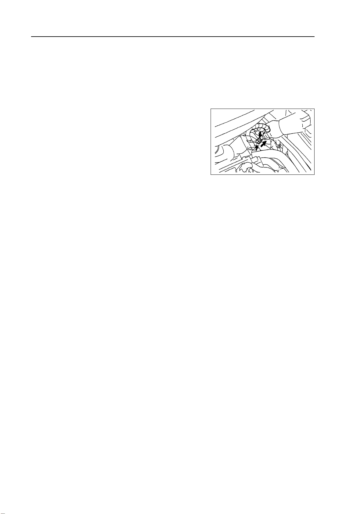
1. Remove engine right bottom shield.
2. Remove drive belt
Slowly turn drive belt tensioner clockwise to loosen it.
Then remove drive belt and put back drive belt tensioner slowly
and gently.
3. Install drive belt
Slowly turn drive belt tensioner clockwise to loosen it.
Then install drive belt and put back drive belt tensioner slowly
and gently.
29
Page 41

Valve clearance
Adjustment
Engine mechanism - Valve clearance
1. Remove engine plastic hood components.
2. Remove ignition coil components [4G18-3705110].
3. Remove cylinder head cover components [4G181003130].
4. Remove engine right bottom shield.
5. T urn crankshaft to cylinder 1 compression top dead
center position.
(a)Turn crankshaft pulley to align its groove with “o” mark on
timing chain hood.
(b)Check dot marks on camshaft timing sprocket and VVT
timing sprocket, and they should be in a line on timing chain
hood surface as shown in the diagram.
Hint: if not, turn crankshaft for one circle again
and align the above marks.
6. Check valve clearance.
(a)Only check the valves shown in the diagram.
(1 ) Measure the clearance between valve tappet and cam-
shaft with plug gauge.
(2)Record valve clearance measuring value exceeding
specification, and this value will be used to determine
valve tappet thickness that needs change.
Valve clearance (cold vehicle)
Mark
Groove
Mark
Mark
Timing chain
hood surface
Intake air
Exhaust
(b) Turn crankshaft for one circle ), and cylinder 4 is
turned to compression top dead center position.
(c) Only check the valves shown in the diagram. Measure valve
clearance (see step (a)).
7. Remove drive belt
Slowly turn drive belt tensioner clockwise to loosen it.
Then remove drive belt and put back drive belt tensioner slowly
and gently.
30
Page 42

Engine mechanism - Valve clearance
8. Remove right engine mounting assembly
(a)Remove PS oil pump reservoir and put it aside.
(b)Place wooden block between jack and engine, properly
place the jack, and then remove right engine mounting
assembly.
9. Remove drive belt tensioner device [4G181300200].
Hint: operate the jack up and down to remove bolts.
10. Adjust valve clearance.
Note: do not turn crankshaft before installing chain
tensioner.
(a)Turn crankshaft to cylinder 1 top dead center position.
(b)Align the marks on timing chain and camshaft timing
sprocket.
(c) Remove 2 bolts and chain tensioner.
Painting
mark
(d) Fix camshaft with adjustable wrench and then loosen
the fixed bolts of exhaust camshaft timing sprocket.
Note: be careful not to damage valve lifter.
(e)As sequences shown in the diagram, loosen camshaft
bearing cover bolts on exhaust camshaft at several
times and remove the bearing cover at the same time.
Fixing
Loosening
(f) As shown in the diagram, remove exhaust camshaft
timing sprocket.
31
Page 43

Engine mechanism - Valve clearance
(g)As sequences shown in the diagram, loosen camshaft
bearing cover bolts on intake camshaft at several times
and remove the bearing cover at the same time.
(h) Hold timing chain with hands and then remove the
camshaft.
(i) As shown in the diagram, tie up the chain with bandage.
Note: be careful not to let anything fall into the
timing chain hood.
(j) Remove valve lifter.
(k) Measure the thickness of this valve lifter with
micrometer.
(1 ) Calculate the thickness of new valve tappet and
adjust valve clearance within specification.
Thickness of new valve lifter
Thickness of old valve lifter
easured valve clearance
:
Exhaust:
Hints:
New valve tappet chosen should be near the value calculated as much as possible.
The thickness of valve tappet is from 5.06mm to 5.74mm,
and there is one specification every 0.02mm, therefore
there are totally 35 different dimensions to chose.
(m) As shown in the diagram, align alignment mark with tim-
ing mark on camshaft timing sprocket, and install timing
chain on the timing sprocket.
Timing remark
chain link
Timing mark
32
Page 44

Engine mechanism - Valve clearance
(n) Check intake side camshaft bearing cover forward re-
mark and figure, and tighten the bolts as sequences
shown in the diagram.
Torque:
(o)Align alignment mark on the chain with timing mark on
camshaft timing sprocket, and place exhaust camshaft
in cylinder head.
(p) Temporarily lock fixed bolts.
(q)Check exhaust side camshaft bearing cover forward
remark and figure, and tighten the bolts as sequences
shown in the diagram.
Torque:
(r) Install camshaft front bearing cover.
Torque:
Timing remark chain link
Timing mark
(s) Fix camshaft with adjustable wrench and then tighten
the fixed bolts of camshaft timing sprocket.
Torque:
Note: be careful not to damage valve lifter.
Fixing
Tightening
33
Page 45

Engine mechanism - Valve clearance
(t) Check the matching marks on timing chain and cam-
shaft timing sprocket, and then align the groove of crankshaft pulley with the timing mark on timing chain hood
as shown in the diagram.
(u)Install chain tensioner.
(1)Check o-ring is clean, and buckle on the hook as
shown in the diagram.
Mark
Groove
Pressing
in
Lifting
Mark
Mark
Timing chain
hood surface
(2)Coat engine oil on the chain tensioner, and then
install it.
Note: when installing the chain temsioner, buckle
on the hook again if plunger has ejected.
(3)Turn crankshaft counterclockwise to separate the
hook from lock pin on the plunger.
Hook
Pin
Pressing in
Separation
Hook
34
Pin
Turning
Page 46

Engine mechanism - Valve clearance
(4 ) Turn crankshaft clockwise, and check the sliding
parts are blocked by plunger.
Plunger
Hint: if the plunger does not eject, press the chain ten-
sion rail toward chain tensioner with screwdriver
or fingers to separate the hook from lock pin and
make the plunger eject.
11.Install cylinder head cover components.
(a)Install cylinder head cover gasket on cylinder head cover.
(b)Eliminate all old sealant (FIPG) materials.
(c) Coat sealant on 2 positions shown in the diagram.
Notes:
Wipe off all the oil stains on junction plane.
After coating sealant, finish installation of cylinder head
cover within 3 minutes.
After installing, do not refill engine oil within 2 minutes.
Pushing
Sealant
Turning
(d ) Install cylinder head cover components with 9 bolts, 2 seal washers and 2 nuts.
Evenly tighten bolts and nuts at several times.
Torque:
Short bolt:
Nut, long bolt etc.: m
12. Install drive belt tensioner device.
Torque: nut:
Bolt:
13. Install fixing bracket absorber on the left of engine.
Torque:
14. Check there is oil leakage.
35
Page 47

Engine mechanism - Engine assembly
Engine assembly
Replacement
1. Take measures to prevent gasoline leaking.
2. Remove engine right bottom shield.
3. Remove engine left bottom shield.
4. Discharge coolant.
5. Remove front wheels.
6. Remove engine plastic hood components.
7. Remove battery.
8. Remove air filter assembly.
9. Remove air filter hose.
10.Remove battery tray.
11.Disassemble fuel hose assembly.
12.Remove throttle cable assembly.
13.Disassemble radiator hose inlet end.
14.Disassemble radiator hose outlet end.
15.Disassemble cold air pipe inlet hose.
16.Disassemble cold air pipe outlet hose.
17.Remove transmission control pull cable assembly.
18.Disassemble warm air water inlet hose [4G18-1300102].
19.Disassemble warm air water outlet hose [4G18-1300108].
20.Disassemble the hoses of all joints to connect vehicle body end.
21.Uncouple engine wire harness.
(a)Remove glove compartment door.
(b)Remove engine wire harness from engine ECU and junction block.
(c) Pull out engine wire harness.
(b)Remove engine wire harness from junction block of engine room.
(e)Remove vehicle body earth wire.
36
Page 48

Engine mechanism - Engine assembly
22. Remove drive belt.
Drive belt tensioner could turn belt tensioner clockwise to
loosen it.
23. Remove alternator mounting components [4G18-
3701100].
24. Remove compressor assembly.
25. Remove front chassis bracket.
26. Remove front exhaust pipe assembly.
27. Remove steering middle shaft assembly.
(a ) Remove steering column seal hole cover.
(b ) Make alignment mark on steering middle shaft.
(c) Remove 2 bolts and steering middle shaft.
(d)Remove steering column cover.
Alignment
mark
28. Remove the nuts on left side of front shaft hub.
(a) Completely knock out the concave part of fixed nuts with
special tool and hammer.
Notes:
Completely knock out the concave part of fixed
nuts before removing the fixed nuts.
Do not damage thread of drive shaft.
Do not sharpen the sharp end of special tool.
Place the special tool in groove with its plane facing
upward.
(b)Remove fixed nuts with socket wrench (30mm).
Hint: perform the same steps at another side.
29. Disassemble left side transversal lever assembly.
Disassemble transversal lever assembly from steering
knuckle with special tool.
Hint: perform the same steps at another side.
Sliding out
Lifting
Special tool
Special tool
37
Page 49

Engine mechanism - Engine assembly
30. Disassemble left end front stabilizer link
assembly.
Fix bolts with hex socket wrench, and then remove nuts.
Hint: perform the same steps at another side.
31. Disassemble lower left control arm assembly.
(a)As shown in the diagram, remove bolt and 2 nuts.
(b) Disassemble drive shaft from shaft hub with plastic
hammer.
Hint: perform the same steps at another side.
32. Remove oil return pipe assembly.
After removing 3 retaining clips and 2 bolts of power steering oil reservoir, remove the oil return pipe from vehicle.
33. Remover engine assembly [4G18-1000000] and
transmission assembly.
(a)Erect engine hanger.
(b) Remove 4 bolts, 2 nuts and right engine mounting
assembly.
(c)Remove through bolt and nut, and then remove left
engine mounting assembly from vehicle.
(d)As shown in the diagram, remove 6 bolts.
(e)Carefully remove engine assembly and transmission
assembly from vehicle.
38
Page 50

Engine mechanism - Engine assembly
(f) As shown in the diagram, install front and rear hooks of
engine.
Torque:
Hint: install engine hooks to front and rear sides of
engine.
(g)Lift engine assembly with chain pulley block and en-
gine lifting device.
34. Remove power steering pump assembly.
35. Remove sub frame together with side member.
(a)Remove front engine mounting assembly and rear en-
gine mounting assembly from engine assembly.
(b)Remove sub frame assembly.
36. Remove starter mounting components
[4G18-3708100].
37. Remove transmission assembly.
(a) Fix crankshaft with special tool, ant then remove 6 bolts.
(b)Remove transmission assembly.
38. Remove clutch assembly [4G18-1601000]
and flywheel components [4G18-1005120J].
(a)Fix crankshaft with special tool, ant remove clutch
assembly at first.
(b)Then remove flywheel components.
39. Remove throttlesupporting plate [4G18-1008202].
40. Remove intake manifold assembly [4G181008200].
Front
Special tool
Engine hook
Rear
41. Remove exhaust manifold upper heat shield components [4G18-1008120].
42. Remove exhaust manifold assembly [4G18-1008100].
43. Remove fuel rail injector assembly [4G18-1112100].
44. Remove ignition coil installation components.
45. Remove oil level gauge tube components [4G18-1002140].
46. Remove temperature regulator assembly [4G18-1306100].
47. Disassemble warm air water outlet pipe components [4G18-1300100].
48. Remove oil pressure alerter [4G18-3757100].
Remove oil pressure alerter with SST.
49. Remove the hoses on all hose joint of engine.
Remove clips and hose.
50. Remove drive belt tensioner device.
51. Remove phase sensor [4G18-3600030].
39
Page 51

Engine mechanism - Engine assembly
52. Remove speed sensor [4G18-3600010].
53. Remove knock sensor.
Remove knock sensor with special tool.
54. Remove water temperature sensor.
Remove water temperature sensor with special tool.
55. Replace engine assembly.
56. Install water temperature sensor.
(a ) Install new gasket to water temperature sensor.
(b)Install water temperature sensor with special tool.
Torque:
57. Install knock sensor.
Install knock sensor with special tool.
Torque: m
58. Install speed sensor.
Install speed sensor and harness clips.
Torque:
59. Install phase sensor.
Torque:
60. Install drive belt tensioner device.
Torque: nut: m
Bolt: m
61. Install the hoses on all hose joint of engine.
Install clips and hose.
62. Install oil pressure alerter.
(a)Clean thread of oil pressure alerter and coat adhesive.
Adhesive: anaerobic pipe thread sealing adhesive 1545
(Kesaixin 1545)
(b)Install oil pressure alerter with special tool.
Torque:
63. Install warm air water outlet pipe components.
Install new gasket and warm air water outlet pipe
components.
Torque: nut: m
Bolt:
40
Page 52

Engine mechanism - Engine assembly
64. Install temperature regulator assembly.
(a)Check temperature regulator assembly o-ring.
(b) Install temperature regulator assembly as shown in the
diagram.
(c) Install engine water inlet pipe joint components.
Torque:
65. Install oil level gauge tube components.
66. Install ignition coil mounting components.
Torque: m
67. Install fuel rail injector assembly.
(a)Install isolator on cylinder head.
(b)Install fuel rail injector assembly.
Torque:
(c) Install fuel pipe retaining clip.
68. Install exhaust manifold gasket and exhaust
manifold assembly.
Torque:
69. Install exhaust manifold upper heat shield
components.
Torque:
70. Install intake manifold assembly.
Install new gasket and intake manifold assembly.
Torque: m
71. Install throttle supporting plate.
Torque:
72. Install flywheel components and clutch assembly.
(a)Fix crankshaft with special tool.
(b)Clean bolts and bolt holes.
(c) Coat bolts with adhesive.
Adhesive: thread locking sealant 1234 (Kesaixin 1234).
(d)Install flywheel components.
As sequences shown in the diagram, tighten bolts at
several times.
Torque: 88 5N m
(e)Install clutch assembly.
Special
tool
41
Page 53

Engine mechanism - Engine assembly
73. Install transmission assembly.
(a)Install transmission assembly.
Torque: bolt A:
Bolt B:
Bolt C:
(b)Install 6 bolts.
Torque:
74. nstall starter mounting components.
Torque: bolt:
Nut:
75. Install sub frame together with side member.
Install front mounting assembly and rear mounting
assembly.
Torque: front:
Rear:
76. Install power steering pump assembly.
Torque:
77. Install engine assembly together with
transmission assembly.
(a)Erect engine together with transmission assembly on
engine crane.
(b)Install engine assembly to vehicle.
(c) Temporarily install side member and 6 bolts.
(d)Install left engine mounting assembly.
Torque:
(e)Install right engine mounting assembly.
(f) Insert special tool into location hole on right side of sub
frame and vehicle.
(g)Temporarily lock bolt A at first, and then lock bolt B.
(h)Insert special tool into location hole on left side of sub
frame and vehicle.
(i) Temporarily lock bolt A at first, and then lock bolt B.
(j) Insert special tool into location hole on right side of sub
frame and vehicle, and then tighten bolts up to speci-
fied torque.
Torque: bolt A: m
Bolt B:
Special
tool
Special tool
42
Page 54

Engine mechanism - Engine assembly
(k) Insert special tool into location hole on left side of sub
frame and vehicle, and then tighten bolts up to specified torque.
Torque: bolt A:
Bolt B: m
(l) As shown in the diagram, tighten 2 bolts.
Torque:
Note: after installing sub frame, check the sub
frame is aligned with location hole on
vehicle.
78. Install compressor.
Torque:
79. Install lower left control arm assembly.
(a)Install drive shaft to steering knucle.
(b)Install lower left control arm.
Torque:
Hint: perform the same steps at another side.
80. Install front left shaft hub nut.
(a)Install fixed nut with socket wrench (39mm).
Torque:
(b)Drive the cutout part of hub nut into groove with chisel.
Hint: perform the same steps at another side.
81. Install left end front stabilizer link assembly.
Fix bolts with hex socket wrench.
Torque:
Hint: perform the same steps at another side.
82. Install left side transversal lever assembly.
(a) Connect transversal lever assembly to steering knucle
and install new nuts.
Torque:
Note:
Do not coat lubricant on thread and conical surface.
After tightening nuts up to specified torque, continue turning nuts for 60¡ãand insert open pin.
(b)Insert new open pin.
83. Connect fuel hose assembly.
84. Install battery tray.
Torque:
43
Page 55

Engine mechanism - Engine assembly
85. Install alternator mounting components.
Torque: 12mm bolt head A:
14mm bolt head B:
86. Install drive belt.
87. Install engine wire harness and all hoses
not connected.
(a)Check and connect all joints of engine wire harness.
(b)Check and connect all hoses.
88. Install transmission control pull cable assembly
and valve control pull cable.
89. Install air filter assembly and its hose.
90. Install steering middle shaft assembly.
(a ) Align alignment mark on steering middle shaft.
(b)Install 2 bolts.
Torque: m
(c) Install steering column cover.
91. Install front exhaust pipe assembly.
92. Install front chassis bracket.
Torque:
93. Install battery and connect wire.
94. Install engine plastic hood components.
95. Install front wheel and engine bottom shield.
96. Refill transmission lubricant.
97. Refill engine oil.
98. Refill coolant.
99. Check there is oil leakage.
100. Check there is coolant leakage.
101. Check idle speed and ignition timing.
102. Check CO/HC.
Alignment
mark
Sliding in
Pulling
44
Page 56

Engine mechanism - Timing chain assembly
Timing chain assembly
Replacement
1. Remove engine left bottom shield.
2. Remove engine right bottom shield.
3. Discharge coolant.
4. Remove engine plastic hood components.
5. Remove drive belt.
6. Remove power steering pump assembly.
7. Remove alternator assembly.
8. Uncouple engine wire harness.
(a)Remove ignition coil joint, PS fuel pressure switch joint,
fuel line control joint and speed sensor joint.
(b)Remove bolts and nuts of fixed earth wire and put aside
engine wire harness.
9. Remove ignition coil assembly.
10. Remove cylinder head cover components.
(a)Remove fuel pipe retaining clip and 2 PCV hoses from
cylinder head cover.
(b)Remove 9 bolts, 2 seal washers, cylinder head cover
components and gasket.
11. Remove right engine mounting assembly.
(a)Remove PS oil pump reservoir and put it aside.
(b)Place wooden block between jack and engine, prop-
erly place the jack, and then remove right engine mounting assembly.
12. Turn crankshaft to cylinder 1 compression top
dead center position.
13. Remove damping pulley components
[4G18-1005110].
Remove pulley bolts with special tool.
Remove damping pulley components with special tool.
Special
tool
Special
tool
45
Page 57

Engine mechanism - Timing chain assembly
14. Remove drive belt tensioner device.
Hint: operate the jack up and down to remove bolts.
15. Remove water pump components [4G18-1307110].
(a)Remove 6 bolts and water pump components.
16. Remove engine stabilizer bracket on engine cross
member.
17. Remove compressor.
18. Remove speed sensor.
19. Remove chain tensioner components
[4G18-1006160].
Note: do not turn crankshaft before installing chain
tensioner components.
20. Remove timing chain hood components
[4G18-1006140].
(a)Remove 11 bolts and nuts.
(b)Remove studs with star wrench.
(c) Pry open timing chain hood from timing chain hood pro-
trusion part between cylinder head and body with screwdriver and remove it.
Note: be careful not to damage timing chain
hood, the contact surface of cylinder head and
body.
21. Remove crankshaft front oil seal assembly
[4G18-1006150].
Remove oil seal with screwdriver.
22. Remove speed sensor signal panel
[4G18-3600011A].
23. Remove chain tension rail components
[4G18-1006120].
24. Remove chain guide rail components
[4G18-1006130].
25. Remove timing chain [4G18-1006110].
Remove it with 2 screwdrivers.
Notes:
Place a piece of cloth to protect engine.
In the state of timing chain separating from timing
sprocket and turning camshaft, turn crankshaft 1/4
circle to avoid valve contacting with piston.
26. Install timing chain.
(a)Turn crankshaft to cylinder 1 compression top dead
center position.
(1)Turn camshaft from hexagon head part of
camshaft, and align dot marks on camshaft timing
sprocket.
46
Page 58

Engine mechanism - Timing chain assembly
(2 ) Use damping pulley bolts to turn crankshaft with its key
toward upward.
(b)Install timing chain on crankshaft timing sprocket and
align the chain link having yellow mark with timing mark
of crankshaft timing sprocket.
Hint: there are 3 yellow chain links on the timing chain.
(c) Install crankshaft timing sprocket with special tool.
Toward port
Timing mark
Set key
Yellow
mark
(d)Install timing chain on camshaft timing sprocket and
align the chain link having yellow mark with camshaft
timing sprocket.
27. Install chain guide rail components.
Torque: m
28. Install chain tension rail components.
Torque:
29. Install speed sensor signal panel.
Install signal panel with “F” mark toward forward.
Special tool
Color (yellow) mark
Timing mark
47
Page 59

Engine mechanism - Timing chain assembly
30. Install crankshaft front oil seal assembly.
(a) Coat a little MP grease on oil seal lip.
(b)Gently knock new oil seal in with special tool and ham-
mer until the seal surface is parallel and level with the
edge of timing chain cover.
Note: do not let oil seal mouth contact with foreign
matters.
31. Install timing chain hood components.
(a)Eliminate all old seal materials from contact surface.
(b) As shown in the diagram, coat sealant on the edge
(diameter 3.5mm-4.5mm).
Sealant: silicon rubber flange sealant 1596 (Kesaixin
1596).
(c) Install timing chain hood with 12 bolts and nuts.
Torque:
Special
tool
Sealant width
Sealant
Chain cover
groove
Notes:
Eliminate all grease on contact surface.
After coating sealant, finish installation of timing chain
hood within 3 minutes.
After installing, do not refill engine oil within 2 minutes.
32. Install chain tensioner components.
(a) Check o-ring is clean, and buckle on the hook as shown
in the diagram.
Sealant
concentration
Entering
Cylinder
head groove
Lifting
48
Hook
Pin
Page 60

Engine mechanism - Timing chain assembly
(b) Coat engine oil on the chain tensioner, and then install
it.
Torque:
Note: when installing the chain temsioner, buckle
on the hook again if plunger has ejected.
33. Install damping pulley.
(a)Align the key groove on the damping pulley with the
key on the crankshaft, and slide damping pulley in.
(b)Install damping pulley bolts with special tool.
Torque:
Pushing into
Special
tool
(c) Turn crankshaft counterclockwise to separate the hook
from lock pin on the plunger.
(d)Turn crankshaft clockwise, and check the chain ten-
sion rail is blocked by plunger.
Hint: if the plunger does not eject, press the chain ten-
sion rail toward chain tensioner with screwdriver
or fingers to separate the hook from lock pin and
make the plunger eject.
Pushing
into
Separation
Hook
Pin
Plunger
Turning
Turning
49
Page 61

Engine mechanism - Timing chain assembly
34. Install speed sensor.
Torque:
35. Install engine fixing bracket
Torque:
36. Install water pump mounting components
[4G18-1307100].
(a)Install new o-ring on water pump.
(b)Install water pump with 6 bolts.
Torque: bolt A:
37. Install drive belt tensioner device.
Torque: nut:
Bolt: m
38. Install right engine mounting assembly.
Torque:
39. Install cylinder head cover components.
(a)Install gasket to cylinder head cover.
(b)Eliminate all old seal materials.
(c) Coat sealant on 2 positions shown in the diagram.
Sealant: silicon rubber flange sealant 1596
(Kesaixin 1596).
Notes:
Eliminate all grease on contact surface.
After coating sealant, finish installation of cylinder
head cover within 3 minutes.
After installing, do not refill engine oil within 2
minutes.
m
(d) Install cylinder head cover and cable bracket with 9 bolts,
2 seal washers and 2 nuts.
Torque: nut:
Bolt: m
40. Install ignition coil mounting components.
Torque:
50
Page 62

Engine mechanism - Timing chain assembly
41. Install alternator mounting components.
Torque: 12mm bolt head:
14mm bolt head: m
42. Refill coolant.
43. Check there is coolant leakage.
44. Check there is oil leakage.
51
Page 63

Engine mechanism - Camshaft
Camshaft
Replacement
1. Remove engine hood.
2. Remove ignition coil assembly.
3. Remove cylinder head cover assembly.
4. Remove engine right bottom shield.
5. T urn crankshaft to cylinder 1 compression top dead
center position.
(a)Turn damping pulley to align its groove with “o” mark on
timing chain hood.
Mark
Mark
(b)Check dot marks on camshaft timing sprocket and VVT
timing sprocket, and they should be in a line on timing chain
hood surface as shown in the diagram.
Hint: if not, turn crankshaft for one circle (360 ) again
and align the above marks.
6. Remove drive belt.
Slowly turn drive belt tensioner clockwise to loosen it.Then
remove drive belt and put back drive belt tensioner slowly and
gently.
7. Remove right engine mounting assembly.
(a)Remove PS oil pump reservoir and put it aside.
(b)Place wooden block between jack and engine, properly
place the jack, and then remove engine fixing bracket shock
absorber.
8. Remove drive belt tensioner assembly.
Hint: operate the jack up and down to remove bolts.
Groove
Mark
Timing chain
hood surface
52
Page 64

Engine mechanism - Camshaft
9. Remove camshaft.
Note: do not turn crankshaft before installing timing chain
tensioner.
(a)Turn crankshaft to cylinder 1 top dead center position.
(b) Make marks on timing chain and camshaft timing sprocket.
(c) Remove 2 bolts and chain tensioner.
Painting
mark
(d) Fix camshaft with variable wrench and then loosen the fixed
bolts of camshaft timing sprocket.
Note: do not damage valve lifter.
(e) As sequences shown in the diagram, loosen camshaft bear-
ing cover bolts on exhaust camshaft at several times and
remove the bearing cover at the same time.
(f) As shown in the diagram, remove exhaust camshaft tim-
ing sprocket.
Fixing
Loosening
(g) As sequences shown in the diagram, loosen camshaft bear-
ing cover bolts on intake camshaft at several times and
remove the bearing cover at the same time.
53
Page 65

Engine mechanism - Camshaft
(h) Hold timing chain with hands and then remove intake
camshaft.
(i) As shown in the diagram, tie up the chain with bandage.
Note: be careful not to let anything fall into the timing
chain hood.
10. Check VVT driver assembly [4G18-1006300].
(a)Check locking state of timing sprocket.
Clip the camshaft with a jaw vice, and ensure VVT driver
is locked tightly.
Note: be careful not to damage intake camshaft.
(b)Release lock pin.
(1)As shown in the diagram, seal 5 oil ducts of intake
camshaft journal with vinyl rubber cloth.
Hint: there are 2 advance side oil ducts in the groove
of intake camshaft, and clog one of them with
rubber block.
(2)In opposite side of the groove, prick a hole on
vinyl rubber cloth of advance side oil duct surface
and delay side oil duct surface.
Delay side
oil duct
Advance
side oil
duct
54
(3)Send in 2 oil ducts (advance side oil duct and
delay side oil duct) with the surface rubber cloth
pricked under the pressure of 150Kpa.
Warning: cover the oil ducts with cloth to avoid
oil injecting out in pushing.
Close
Open
Vinyl rubber cloth
Delay side
oil duct
Close
Open
Rubber block
Advance
side oil
duct
Page 66

Engine mechanism - Camshaft
(4)Ensure whether the timing sprocket of VVT driver
will turn toward timing advance direction in decreasing the pressure of timing delay oil duct.
(5)When camshaft timing sprocket turns at max.
timing advance position, release the air pressure
in timing delay side oil duct, and then release the
air in timing advance side oil duct.
Hint: camshaft timing sprocket will turn only af-
ter the lock pin is released.
Warning: if the air pressure in timing advance side oil duct is released earlier than that
in timing delay side oil duct, VVT driver assembly will move suddenly toward
delay side, and the lock pin will be damaged.
(c) Check rotating is smooth.
Besides max. delay position, turn VVT driver assembly within rotating rang and check rotating is
smooth.
Warning: Perform inspection with hands but not with
compressed air.
(d)Check the fixing state of max. delay position.
Ensure camshaft timing sprocket assembly is fixed at
max. delay position.
11. Remove VVT driver assembly.
(a) Clip the camshaft with a jaw vice, and ensure VVT driver
is locked tightly.
Warning: be careful not to damage camshaft.
(b)As shown in the diagram, seal 5 oil ducts of camshaft
journal with vinyl rubber cloth.
Hint: there are 2 advance side oil ducts in the
groove of camshaft, and clog one of them
with rubber block.
(c) In opposite side of the groove, respectively prick a hole
on vinyl rubber cloth of advance side oil duct surface
and delay side oil duct surface.
(d)Send in 2 oil ducts (advance side oil duct and delay
side oil duct) with the surface rubber cloth pricked
under the pressure of 150Kpa.
Warning: cover the oil ducts with cloth to avoid
oil injecting out in pushing.
(e)Ensure whether the timing sprocket of VVT driver will
turn toward timing advance direction in decreasing the
pressure of timing delay oil duct.
Hint: camshaft timing sprocket will turn toward
advance direction only after the lock pin is
released.
(f) When camshaft timing sprocket turns at max. timing
advance position, release the air pressure in timing
delay side oil duct, and then release the air in timing
advance side oil duct.
Delay side
oil duct
Dropping
pressure
Delay side
oil duct
Close
Open
Vinyl rubber cloth
Delay side
oil duct
Delay side
oil duct
Dropping
pressure
Advance
side oil
duct
Maintaining
pressure
Advance
side oil
duct
Close
Open
Rubber block
Advance
side oil
duct
Advance
side oil
duct
Maintaining
pressure
55
Page 67

Engine mechanism - Camshaft
Warning: if the air pressure in timing advance side oil duct is released earlier than that in
timing delay side oil duct, VVT driver assembly will move suddenly toward
delay side.This will cause the damage of lock pin.
(g ) Remove VVT drive fixed bolts.
Notes:
It is strictly forbidden to remove other 4 bolts.
Under the condition of repeating using camshaft
timing sprocket, release lock pin at first, and then
install sprocket.
12. Install VVT driver assembly.
13. Install camshaft.
Put VVT driver assembly together with intake camshaft.
(a)As shown in the diagram, gently make VVT assembly
hold camshaft and turn it toward left until straight pin is
inserted into groove.
Warning: it is strictly forbidden to turn camshaft
timing sprocket toward timing delay side
(toward right).
Flange bolt
Straight pin
Straight pin
key
groove
(b)Check there is no clearance between sprocket flange
and camshaft.
(c)Fix camshaft timing sprocket and then tighten flange
bolt.
Torque: 70 ±5N.m
(d ) Check VVT driver assembly could move to timing
delay side and is locked at max. timing delay position.
(f) As shown in the diagram, align alignment mark with
timing mark on camshaft timing sprocket, and install
timing chain on the timing sprocket.
(g)Check forward mark and figure, and tighten bolts as
sequences shown in the diagram.
Torque: 13 ±0.78N.m
Timing remark
chain link
Timing mark
Timing remark chain link
(h)Align alignment mark on the chain with timing mark on
camshaft timing sprocket, and place exhaust camshaft
in cylinder head.
56
Timing mark
Page 68

Engine mechanism - Camshaft
(i) Temporarily tighten fixed bolts.
(j) Check forward mark and figure, and tighten bolts as
sequences shown in the diagram.
Torque: ±0.78N.m
(k) Install camshaft front bearing cover.
Torque: 23 ±1.38N.m
(l) Fix camshaft with variable wrench and then tighten the
fixed bolts of exhaust camshaft timing sprocket.
Torque: 54 ±10.8N.m
Note: be careful not to damage valve lifter.
(m)Check the alignment marks on timing chain and cam-
shaft timing sprocket, and then align the groove of damping pulley with the timing mark on timing chain hood as
shown in the diagram.
Tightening
Mark
Fixing
Mark
Mark
Timing chain hood
Groove
57
Page 69

Engine mechanism - Camshaft
(n ) Install chain tensioner components.
(1)Check o-ring is clean, and buckle on the hook as
shown in the diagram.
(2)Coat engine oil on the chain tensioner, and then
install it.
Torque: 9 ±1.8N.m
Note: when installing the chain temsioner,
buckle on the hook again if plunger has
ejected.
Lifting
Pressing
in
Hook
Pin
Pushing into
(3)Turn crankshaft counterclockwise to separate the
hook from lock pin on the plunger.
(4)Turn crankshaft clockwise, and check the sliding
parts are blocked by plunger.
Hint: if the plunger does not eject, press the ten-
sion rail toward chain tensioner with
screwdriver or fingers to separate the hook
from lock pin and make the plunger eject.
Pushing into
Sepa-
rate
Hook
Pin
Plunger
Turning
58
Page 70

Engine mechanism - Camshaft
14. Adjust valve clearance.
15. Install cylinder head cover components.
(a)Install gasket to cylinder head cover.
(b)Eliminate all old sealant (FIPG) materials.
(c) Coat sealant on position shown in the diagram.
Sealant: silicon rubber flange sealant 1596 (Kesaixin
1596).
Notes:
Eliminate all oil on contact surface.
After coating sealant, finish installation of cylinder
head cover within 3 minutes.
After installing, do not refill engine oil within 2
minutes.
(d)Install cylinder head cover and harness bracket with 9
bolts, 2 oil seal washers and 2 nuts.
Evenly tighten bolts and nuts at several times.
Torque: nut: 29 ±5.8N.m
Bolt: 69 ±13.8N.m
16. Install drive belt tensioner device.
Torque: nut: 29 ±5.8N.m
Bolt: 69 ±13.8N.m
17. Install right engine mounting assembly.
T orque: 52N.m
18. Check there is oil leakage.
59
Page 71

Engine mechanism - Crankshaft front oil seal assembly
Crankshaft front oil seal assembly
Replacement
1. Remove engine right bottom shield.
2. Remove drive belt.
Slowly turn drive belt tensioner clockwise to loosen it. Then
remove drive belt and put back drive belt tensioner slowly and
gently.
3. Remove right engine mounting assembly.
(a)Remove PS oil pump reservoir and put it aside.
(b)Place wooden block between jack and engine, properly
place the jack, and then remove right engine mounting
assembly.
4. remove damping pulley.
(a)Remove pulley bolts with special tool.
(b)Remove damping pulley with special tool.
Special
tool
Special
tool
60
Page 72

Engine mechanism - Crankshaft front oil seal assembly
5. Remove crankshaft front oil seal.
(a) Cut oil seal lip with blade.
(b) Prize out oil seal with flat screwdriver whose sharp end is
winded with tape.
Note: check crankshaft is damaged after removing oil
seal, and repair with abrasive paper (#400) if it
is damaged.
6. Install crankshaft front oil seal.
(a) Coat a little MP grease on new oil seal lip.
Note: do not let oil seal lip contact with foreign
matters.
(b)Gently knock new oil seal in with special tool and hammer
until the seal surface is parallel and level with the end surface edge of mounting hole.
Note: wipe off redundant grease on crankshaft.
7. Install damping pulley.
(a) Align the key groove on the pulley with the key on the
crankshaft, and slide pulley in.
(b)Install pulley bolts with special tool.
Torque: m
Cut
position
Prizing out
Special
tool
Special
tool
8. Install right engine mounting assembly.
Torque:
9. Check there is oil leakage.
61
Page 73

Engine mechanism - Crankshaft rear oil seal assembly
Crankshaft rear oil seal assembly
Replacement
1. Remove transmission assembly.
2. Remove clutch assembly and flywheel components.
Fix crankshaft with special tool, remove clutch assembly at
first, and then remove flywheel components.
3. Remove crankshaft rear oil seal.
(a)Cut oil seal mouth with blade.
(b)Prize out oil seal with flathead screwdriver whose sharp
end is winded with tape.
Note: check crankshaft is damaged after removing oil
seal, and repair with abrasive paper (#400) if it is
damaged.
Special
tool
4. Install crankshaft rear oil seal [4G18-1002130].
(a) Coat a little MP grease on new oil seal lip.
Note: do not let oil seal lip contact with foreign
matters.
(b)Gently knock new oil seal in with special tool and hammer
until the seal surface is parallel and level with the end surface edge of mounting hole.
Note: wipe off redundant grease on crankshaft.
5. Install flywheel components and clutch assembly.
(a)Fix crankshaft with special tool.
(b)Clean bolts and bolt holes.
(c) Coat bolts with adhesive.
Adhesive: thread locking adhesive 1234 (Kesaixin 1234)
Special
tool
Cut
position
(d)Install flywheel components.
As sequences shown in the diagram, tighten bolts at several times.
Torque:
(e)Install clutch assembly.
6. Install transmission assembly.
62
Page 74

Engine mechanism - Cylinder cover gasket components
Cylinder cover gasket components
Replacement
1. Take measures to prevent gasoline leaking.
2. Remove timing chain assembly.
3. Remove camshaft.
As sequences shown in the diagram, evenly loosen at
several times, and remove 19 bearing cover bolts, and then
remove 9 bearing covers of intake camshaft and exhaust
camshaft.
4. Remove cylinder head assembly.
(a)Remove warm air water outlet pipe from cylinder head.
(b)As shown in the diagram, evenly loosen 10 cylinder head
bolts with 10mm dual hexagonal sleeves at several times,
and then remove 10 cylinder head bolts and plain washer.
Notes:
Be careful not to let washer fall into cylinder head.
Incorrect disassembling sequence will cause cylin-
der head warp or chap.
5. Remove cylinder head gasket components
[4G18-1003160].
6. Install cylinder head gasket components.
Put new cylinder head gasket on the cylinder body.
Notes:
Pay attention to installation direction.
Gently put down cylinder head to avoid damaging
cylinder head gasket.
7. Install cylinder head assembly.
Hint: Lock up cylinder head bolts as 2 steps.
(a) Coat a thin layer of engine oil at bolt thread and the bottom
of bolt head.
(b)As shown in the diagram, evenly tighten 10 cylinder head
bolts and plain washer with 10mm dual hexagonal sleeves
at several times.
Torque:
63
Page 75

Engine mechanism - Cylinder cover gasket components
(c) Tighten each cylinder head bolt in turn again.
Torque: m
(d ) Install heating air water outlet pipe components.
Torque:
8. Install camshaft.
(a)Coat engine oil on camshaft journal.
(b ) Put 2 camshafts on cylinder head and with cylinder 1 cam-
shaft end toward the direction shown in the diagram.
(c) Check forward remarks and figures of all bearing cover, and
tighten the bolts as sequences shown in the diagram.
Torque:
Camshaft front bearing cover:
Camshaft bearing cover:
9. Check idle speed and ignition timing.
10. Check compression pressure.
11. Check CO/HC.
64
Page 76

Exhaust - Exhaust pipe assembly
Exhaust
Exhaust pipe assembly
Removing, installing and disassembling, assembling
1. Remove oxygen sensor.
(a)Uncouple oxygen sensor joint.
(b)Remove oxygen sensor.
2. Remove exhaust pipe guard [64000051].
3. Remove front exhaust pipe together with three-way catalytic converter assembly
[64000042].
4. Remove middle exhaust pipe together with middle silencing device assembly [64000043].
5. Remove rear exhaust pipe together with rear silencing device assembly [64000044].
6. Install front exhaust pipe together with three-way catalytic converter assembly [64000042].
(a)Measure free length of compression spring with vernier caliper.
Free length: 43mm
Hint: if the free length does dot reach the standard value, it is necessary to replace compression spring.
(b ) Gently knock silencing device inlet seal ring to exhaust manifold with hammer and wooden block until
the surfaces are parallel and level with each other.
Notes:
Gently knock gasket toward positive direction.
Do not repeat using the gasket that has been removed.
Do not push the gasket in by means of tightening
bolt connection.
(c) Install exhaust pipe.
Torque: 43 N.m
7. Install oxygen sensor.
Torque: 44 N.m
Gaskett
8. Install middle exhaust pipe together with middle silencing device assembly [64000043].
Couple front intake pipe of middle exhaust pipe together with
middle silencing device assembly with outlet pipe of front exhaust pipe together with three-way catalytic converter using a
new gasket.Torque: 43 N.m
9. Install rear exhaust pipe together with rear guard
assembly [64000044].
(a)Measure free length of compression spring with vernier
caliper.
Free length: 40mm
Hint: if the free length does dot reach the standard value, it is necessary to replace com-
pression spring.
(b ) Install tail pipe to front pipe using a new gasket.
Torque: 43 N.m
10. Install front exhaust pipe guard [64000051].
11. Check there is gas leakage with exhaust system.
Tail pipe side
wooden
block
Gasket
65
Page 77

Cooling - Cooling syste
Cooling
Cooling system
On-vehicle inspection
1. Check there is leakage with cooling system.
Warning: when the temperature of engine and radiator is
high, do not remove radiator cap to avoid being scalded, because coolant and steam will
spurt under high pressure.
(a)Refill coolant to radiator, and install radiator cap tester.
(b)Preheat engine.
(c) Pump tester to make pressure go up to 118KPa, and check
the pressure falls.
Hint: if the pressure falls, check there is leakage with
hose, radiator or water pump, and check heater,
cylinder body and cylinder head if no external leakage is found.
2. Check engine coolant level in reservoir.
Engine coolant level should be between “Low” and “Full” mark line.
Hint: if the level is too low, check there is leakage and refill coolant to “Full” mark line.
3. Check engine coolant quality.
(a)Remove radiator cap.
Warning: when the temperature of engine and radiator is high, do not remove radiator cap to
avoid being scalded, because coolant and steam will spurt under high pressure.
(b)Check there is too much rust deposit around radiator cap or at outlet and check there is flake; there
should not be oil in the coolant.
Hint: if coolant is too dirty, it is required to replace coolant.
(c) Install back radiator cap.
Inspection
1. Temperature regulator
Hint: the figure on temperature regulator is the
opening temperature of valve.
66
Page 78

Cooling - Cooling syste
(a) Immerse temperature regulator into water and heat
gradually.
(b)Check opening temperature of valve.
Opening temperature of valve: 80 84
Hint: if opening temperature of valve is not within
specified range, it is required to replace temperature regulator.
(c) Check opening of valve.
Opening of valve:
Temperature Degree of valve opening
Hint: if degree of valve opening is not within speci-
fied range, it is required to replace temperature regulator.
(a) When temperature regulator is at low temperature (below
), check valve is tightly closed.
Hint: if the valve could not be closed, it is required to
replace temperature regulator.
2. Radiator cap assembly
Notes:
If radiator is dirty, wash it with clean water.
Before using radiator cap tester, dampen relief valve
and pressure valve with coolant or water.
(a)Use radiator cap tester to slowly pump radiator cap
tester, and check the air is released by vacuum valve.
Pumping speed: 1 time /(3 seconds or more)
Note: pump radiator tester with constant speed.
Hints:
Pumping speed: 1 time /(3 seconds or more)
If air could not be released by vacuum valve,
please replace radiator cap.
(b)Pump tester and check opening pressure of relief valve.
Standard opening pressure: 74-108KPa
Min. opening pressure: 59KPa
Note: pumping speed means that the speed could be increased after the first time pumping
speed (to close vacuum valve).
Hints:
Pumping speed: 1 time within 1 second
Max. reading of tester is opening pressure.
If opening pressure is less than min. value, please replace radiator cap.
67
Page 79

Cooling - Cooling fan system
Cooling fan system
On-vehicle inspection
1. Check cooling fan function at low temperature (below 95 ).
(a)Turn ignition switch to ON.
(b)Check cooling fan is stopped.
Hint: if it is not stopped, check cooling fan relay and water temperature sensor, or check the
joint or wire harness between them.
(c) Uncouple water temperature sensor joint.
(d)Check cooling fan runs.
If it does not run, check fuse, cooling fan relay, engine ECU and cooling fan, or check there is short
circuit between them.
(e)Connect back water temperature sensor joint.
2. Check cooling fan function at high temperature (above 95 ).
(a ) Start engine and increase coolant temperature up to above
Hint: water temperature is the value measured by water temperature sensor on water outlet.
(d)Check cooling fan runs.
Hint: if it does not run, please replace water temperature sensor.
3. Check cooling fan.
(a)Uncouple cooling fan joint.
(b)Connect battery and ampere meter to cooling fan joint.
(c) Check cooling fan runs normally and check ampere meter reading.Standard current: 7 12A
(d)Connect back cooling fan joint.
Inspection
1. Electronic fan relay [67000064]
Conditions
Normal state Conduction
Supply battery voltage
to No. 1 and No. 2
terminals
Terminal connected
by three-use meter
2. Electronic fan relay II [67000072]
Conditions
Normal state
Supply battery voltage
to No. 1 and No. 2
terminals
Terminal connected
by three-use meter
3. Cooling fan speed adjusting resistance assembly
[67000001]
Measure resistance between terminals with ohmmeter.
Resistance: at normal temperature: 1.3
Specified
conditions
Conduction
Specified
conditions
Conduction
Conduction
68
Page 80

Cooling - Water pump assembly
Water pump assembly
Replacement
1. Remove engine right bottom shield.
2. Discharge engine coolant.
3. Remove drive belt.
Slowly turn drive belt tensioner clockwise to loosen the belt;
then remove drive belt and put back drive belt tensioner slowly
to completely loosen the tensioner.
4. Remove alternator assembly.
(a)Remove rubber cover and nuts.
(b)Uncouple alternator joint.
(c) Remove 2 bolts and alternator.
5. Remove water pump assembly.
Remove 6 bolts, water pump and o-ring.
69
Page 81

Cooling - Water pump assembly
6. Install water pump assembly.
(a)Install new o-ring on water pump.
(b)Install water pump with 6 bolts.
Torque: bolt A:
Bolt B:
7. Install alternator mounting components.
Torque: 12mm bolt head:
14mm bolt head:
8. Refill engine coolant.
9. Check there is leakage with coolant.
70
Page 82

Cooling - Temperature regulator components
Temperature regulator components
Replacement
1. Remove engine right bottom shield.
2. Discharge engine coolant.
3. Remove drive belt.
Slowly turn drive belt tensioner clockwise to loosen the belt;
then remove drive belt and put back the tensioner slowly to
completely loosen it.
4. Remove alternator components.
(a)Remove rubber cover and nuts.
(b)Uncouple alternator joint.
(c) Remove 2 bolts and alternator.
5. Remove water inlet pipe.
6. Remove temperature regulator.
7. Install temperature regulator.
(a ) Install new gasket to temperature regulator.
(b) As shown in the diagram, install temperature regulator with
inching valve toward upward.
8. Install water inlet pipe and joint.
Torque:
9. Install alternator installation components.
Torque: 12mm bolt head: m
14mm bolt head:
10. Refill engine coolant.
11. Check there is leakage with coolant.
71
Page 83

Cooling - Radiator with electronic fan assembly
Radiator with electronic fan assembly
Replacement
1. Discharge coolant (see Page 73).
2. Disassemble radiator water inlet hose [64000062].
3. Disassemble radiator water outlet hose [64000063].
4. Disassemble No.1 oil cooler inlet pipe (auto gear).
5. Disassemble No.1 oil cooler outlet pipe (auto gear).
6. Disassemble fixing clips of 2 wire harnesses from fan cover.
7. Remove mounting bracket assembly on radiator [64000058].
8. Remove radiator together with electronic fan assembly [64000057].
9. Remove electronic fan together with fan cover assembly [64000060].
(a ) Screw off fixed nuts connecting electronic fan together with fan cover assembly with radiator.
(b ) Uncouple fan motor joint.
(c) Remove 2 bolts of fan.
(d ) Remove fan motor at the same time.
10. Replace and install as sequences opposite to the above.
11. Refill engine coolant (see Page 73).
12. Check there is leakage with coolant (see Page 66).
72
Page 84

Cooling - Coolant
Coolant
Replacement
1. Discharge engine coolant.
Warning: when the temperature of engine and radiator is high, do not remove radiator cap to
avoid being scalded, because coolant and steam will spurt under high pressure.
(a)Remove radiator cap.
(b)Open radiator drain valve and engine drain valve.
Engine drain valve
Radiator cap
Radiator drain valve
Drain pipe
2. Refill engine coolant.
(a)Lock 2 drain valves and pour coolant into radiator until it is full.
Hints:
Press radiator water inlet hose and outlet hose with hands several times.
If coolant level is too low, please refill coolant again.
(b)Screw down radiator cap.
(c) Pour coolant into expansion tank until the level is up to “FULL” mark line.
(d ) Run engine with vehicle warning up until thermostat valve is opened.
Hint:During vehicle warning up, press radiator water inlet hose and outlet hose with hands
several times.
(e)Engine flames out until coolant temperature falls to “cold”. Then open radiator cap and check coolant
level.
(f) If coolant level is too low, please perform the above steps again.
(g)If coolant level is not too low, please adjust expansion tank coolant level.
3. Check there is leakage with coolant.
(a)Refill engine coolant to radiator, and install radiator cap tester.
(b)Pressurize radiator to 118kPa, and check there is leakage.
73
Page 85

Lubrication - lubricating system
Lubrication
Lubricating system
On-vehicle inspection
1. Check oil level.
During engine warming up and after it flames out for 5 minutes, check oil level, and the level should
be between two marks on oil dipstick at the moment.If oil level is too low, check there is leakage, and
refill oil up to upper mark on oil dipstick.
Note: oil level should not be above upper mark on oil
dipstick.
2. Check oil quality.
(a)Check there is deterioration, water penetration, color
change or thinning with oil.
(b)If oil quality becomes poor, please replace with new oil.
Hint: oil grades: API, SH, SJ, SG grade oil or ILSAC
multigrade oil. Recommended viscosity is
shown as below.
The temperature increases from left to right.
3. Remove oil pressure alerter assembly.
(a)Uncouple oil pressure alerter joint.
(b)Install oil pressure alerter with special tool.
Recommended viscosity (SAE)
Temperature range in forecasting next
oil replacement
4. Install oil pressure gauge.
Install oil pressure gauge.
5. Warm up vehicle.
6. Check oil pressure.
Oil pressure:
7. Install oil pressure alerter.
(a)Coat adhesive on 2nd or 3rd circle thread of oil pressure
alerter.
Adhesive: anaerobic pipe thread sealing adhesive
1545 (Kesaixin 1545).
(b)Install oil pressure alerter with special tool.
Torque: m
(c) Connect oil pressure alerter joint.
8. Start engine and check there is leakage.
Oil pressure alerter
Oil pressure gauge
Adhesive
74
Page 86

Lubrication - Oil filter assembly
Oil filter assembly
Replacement
Warning:
Long-term or repeat contacting mineral oil will cause decomposing of natural fat on skin, which
will result in dry and sensitive skin and skin rankling. Used oil has potential harm and may cause
carcinoma cutis.
When replacing engine oil, always wear protective clothes and gloves to avoid waste oil
penetrating, and reduce the frequency and time of skin contacting waster oil, and clean with
soapy water or clean water not with gasoline, thinner or solvent if skin contacts waste oil.
To protect environment, waste oil and oil filter must be abandoned at named place.
1. Remove engine right bottom shield.
2. Discharge engine oil.
3. Remove oil filter assembly [4G18-1012100].
Remove oil filter with special tool.
4. Install oil filter assembly.
(a)Check and clean oil filter junction plane.
(b)Coat oil seal of new oil filter with clean oil.
(c) Tighten oil filter with hands to the extent that oil seal
just touches fixing base.
(d)Tighten oil filter for another 3/4 circle with special tool.
5. Install oil drain plug [4G18-1009101].
Clean oil drain plug, and install it back after replacing oil drain plug gasket.
Torque:
Special tool
3/4 circle
Special tool
6. Refill engine oil.
7. Check there is oil leakage.
75
Page 87

Lubrication - Oil pump assembly
Oil pump assembly
Replacement
1. Remove timing chain assembly (see Page 45).
2. Remove oil pump assembly [4G18-1011100].
Remove 5 bolts, oil pump and oil pump gasket.
3. Install oil pump assembly.
(a ) Install new gasket on cylinder body.
(b)Align the guide groove of oil pump drive rotor with the key
on crankshaft, and slide the oil pump in.
(c) Install oil pump with 5 bolts.
Torque:
76
Page 88

Ignition - Ignition system
Ignition
Ignition system
Inspection
1. Spark plug
(a)Clean spark plug.
Air pressure: below 588kPa.
Time: 20 s or less
(b) Check the damage condition of spark plug and insulator. If
there is something abnormal, please replace with new spark
plug.
Recommended spark plug specification:
Made in Xianghuoju Company: K6RTC
Spark plug
cleane
(c) Adjust electrode gap.
Electrode gap: 0.8mm
On-vehicle inspection
1. Phase sensor
(a)Turn on ignition switch but do not start engine, and place digital universal meter at DC voltage gear,
then connect 2 terminals respectively to 1# pin and 3# pin of sensor, and ensure the voltage is 12V.
(b)Start engine, and phase signal is read by 2# pin via vehicle oscilloscope.
2. Speed Sensor
(a)Remove speed sensor joint.
(b) Place digital universal meter at ohm gear, and connect 2 terminals respectively to 2# pin and 3# pin of
sensor, and the resistance at should be 8601/2 ±801/2.
(c) Connect speed sensor joint.
(d) Place digital universal meter at AC voltage gear , and connect 2 terminals respectively to 2# pin and 3
pin of sensor, and start engine, there should be voltage output at the moment.(It is recommended to
check with vehicle oscilloscope)
#
77
Page 89

Ignition - Ignition system
3. Inspection of ignition coil (including igniter) and spark test
(a)Check DTC.
Note: if there is display with DTC, perform trouble shooting according to DTC procedure.
(b)Check there is spark.
(1)Remove ignition coil (including igniter).
(2)Remove spark plug with 16mm spark plug sleeve.
(3)Install spark plug to each ignition coil (including igniter), and connect ignition coil joint.
(4)Uncouple joints of 4 injection nozzles.
(5)Earth spark plug.
(6)Check spark with engine running.
Notes:
Be sure to earth spark plug during checking.
When there is falling or collision with ignition coil,please replace with a new one
Running engine time for each time should not be more than 2 seconds.
If there is no spark, please perform test as the following steps.
(c) Install spark plug with 16mm spark plug sleeve.
Torque:
(d ) Install ignition coil and igniter.
Torque:
4. Test procedure in the state of not spark
Spark test
Replace bad spark plug with a good one, and perform spark test again.
Replace with a new ignition coil (including igniter)
Replace all spark plugs with new ones, and perform spark plug again.
Replace bad ignition coil (including igniter) with a new one.
Perform step 3
Replace with a new spark plug
Spark plug is not good
78
Page 90

Starting and charging - Starting system
Starting and charging
Starting system
Inspection
1. Starter installation components
Note: this test must be finished within 3 to 5 seconds to
avoid burning out coil.
(a)Remove nut at C terminal to uncouple wire of field coil.
(b)As shown in the diagram, connect battery wire to electro-
magnetic switch, and check drive pinion is pushed outside,
(pull-in coil and hold-in coil).
Terminal C
Terminal 50
(c) As shown in the diagram, uncouple negative wire from ter-
minal C after the above connections, and check drive pin-
ion is still at the state of being pushed outside.(Hold-in coil)
(d)Push drive pinion toward armature side, and measure the
clearance between drive pinion end and stop ring.
Standard clearance: 1.0~5.0mm
(e)Uncouple negative wire from electromagnetic switch
housing, and check drive pinion returns back to original
position toward inside.
Terminal C
Terminal 50
Terminal C
Terminal 50
79
Page 91

Starting and charging - Starting system
(f) Connect magnetic field coil wire to terminal C.
(h) Torque:
(i) Clamp starter with jaw vice.
(j) As shown in the diagram, connect battery with ampere
meter.
(k) Read current value displayed on ampere meter.
(l) Current value specification: 90 A or lower at 11.5 V.
2. Starter relay
Terminal 50
Ampere
meter
Terminal 30
Conditions
Terminal connected
by three-use meter
Specified
conditions
Normal state Conduction
Supply battery voltage
to No. 1 and No. 2
Conduction
terminals
80
Page 92

Starting and charging - Charging system
Charging system
Precautions
1. Check positive and negative wire of battery is connected correctly.
2. When performing quick charge to battery, please
uncouple battery wire.
3. Do not test with high-pressure insulation resistance
tester.
4. do not uncouple battery wire during engine running.
81
Page 93

Starting and charging - Charging system
On-vehicle inspection
1. Check battery voltage.
(a) If extinguishing time of engine is not more than 20 minutes
after driving, please turn on ignition switch and electric
equipment (head lamp, blower motor and rear window
defog line etc.) for about 60 seconds to eliminate surface
charging during driving.
(b)Turn ignition switch to OFF, and then switch off electric
equipment system.
(c) Measure the voltage between battery negative (-) terminal
and positive (+) terminal.
Standard voltage: 12.5~12.9V at 20 .
Hint: if the voltage is lower than standard
specification, please charge battery.
(d)As shown in the diagram, check battery window.
Hints:
Green: OK
White: requiring charge
Black: replacing battery
2. Check battery joint, fusible link and slow fuse (100A).
(a ) Check battery joint is loose or eroded.
(b ) Check fast fuse and slow fuse (100A) are in conduction.
3. Check drive belt.
(a)Check belt is excessively worn or cable is broken etc.
Hints:
If any inferior part is found, please replace drive
belt.
It is allowable for the crack at the edge of drive belt
rib.
If there is block falling with belt rib, please replace with
new belt.
(b)Check the belt is correctly installed in guide groove.
Hint: Check with hands to ensure that the belt does
not slide out from the groove of pulley bottom.
4. Visually check alternator wire harness.
Check the condition of wire is perfect.
5. Listen to whether there is abnormal sound with alternator.
There should not be abnormal sound with alternator during engine running.
6. Check the circuit of charge alarm light.
(a)Turn ignition switch to “ON”, and check charge alarm light is on.
(b)Start engine, and charge alarm light should be off.
Hint: if the function of charge alarm light does not conform to the regulation, please perform
trouble shooting to the circuit of charge alarm light.
Green White Black
82
Page 94

Starting and charging - Charging system
7. Check charging system circuit at no load.
(a)If there is battery/alternator tester, please connect tester
to charging system circuit as manufacturer instruction.
(b)If there is no battery/alternator tester, please connect volt-
meter to charging system circuit as the following way.
z Uncouple wire on engine terminal B, and connect wire
on negative (-) test bar of ampere meter.
Battery
z Connect positive (+) test bar of ampere meter to alter-
nator terminal B.
z Connect positive (+) test bar of voltmeter to alternator
terminal B.
z Connect negative test bar of voltmeter to earth.
(c) Check charge system circuit.
(1)Check the readings of ampere meter and voltmeter with engine from idle speed to 2000rpm.
Standard current: 10A or less.
Standard voltage: 12.9~14.9V.
Hints:
If voltmeter reading is more than standard value, please replace with new voltage regulator.
If voltmeter reading is less than standard value, please check voltage regulator and alternator
as the following way.
(2)Earth terminal F, start engine and check voltage of
terminal B.
Terminal F
Hints:
If voltmeter reading is more than standard value,
please replace with new voltage regulator.
If voltmeter reading is less than standard value,
please check alternator.
Ampere meter
Voltmeter
Uncoupling
terminal B wire
Alternator
8. Check charging system circuit at load.
(a)Turn on high beam of front combination lamps with engine running at 2000rpm,and turn blower to
“HI” position.
(b)Check the reading of ampere meter.
Standard amperage: 30A or more.
Hints:
If amperage is less than standard value, please repair alternator.
If battery is under the state of full charge, amperage may be less than standard value sometimes.
83
Page 95

Starting and charging - Alternator components
Alternator components
Replacement
1. Remove engine right bottom shield.
2. Remove drive belt.
Slowly turn drive belt tensioner clockwise to loosen the belt,
then remove drive belt and put back the tensioner slowly to
completely loosen it.
3. Remove alternator components.
(a)Remove rubber cover and nuts.
(b)Uncouple alternator joint.
(c) Remove 2 bolts and alternator.
4. Install alternator components.
Torque: 12mm head bolt : m
14mm head bolt :
84
Page 96

Starting and charging - Starter components
Starter components
Replacement
1. Remove engine lower left shield.
2. Remove starter components.
(b)Uncouple starter joint.
(b)Remove nuts, and uncouple starter wire.
(c) Remove 2 bolts and starter.
3. Install Starter components.
Torque: bolt:
Wire harness:
85
Page 97

Front suspension - front suspension system
Front suspension
Front suspension system
Table on trouble occurrence
This table could help you find out failure causes, and each figure in the table indicates the possible
sequence of failure causes, please check every part as the sequence, and replace if necessary.
Trouble occurrence Possible trouble part Pages to refer to
1. Tire (abrasion or improper tire pressure) 109
2. Wheel alignment (incorrect) 87
Deflection/single side 3. Steering linkage (looseness or abrasion) -
4. Shaft hub bearing (abrasion) 123
5. Suspension parts (abrasion) -
6. Steering gear (poor adjustment or breakage) -
1. Vehicle (overload) -
Bottoming 2. Spring (elastic fatigue) 90
3. Absorber (abrasion) 90
1. Tire (abrasion or improper tire pressure) 109
Swaying left and right/ 2. Stabilizer bar (bending or breakage) 96
shaking forward and backward
Front wheel shimmy 4. Wheel alignment (incorrect) 87
Abnormal tire abrasion 2. Wheel alignment (incorrect) 87
3. Absorber (abrasion) 90
1. Tire (abrasion or improper tire pressure) 109
2. Wheel (poor balance) 109
3. Absorber (abrasion) 90
5. Ball joint (abrasion) 99
6. Shaft hub bearing (looseness or abrasion) 12 3
7. Steering linkage (looseness or abrasion) -
8. Steering gear (poor adjustment or breakage) -
1. Tire (abrasion or improper tire pressure) 109
3. Absorber(abrasion) 9 0
4. Suspension parts (abrasion) -
86
Page 98

Front suspension - Front wheel alignment
Front wheel alignment
Adjustment
1. Inspection
(a)Check tire is worn and inflation pressure is proper.
Tire inflation pressure under normal temperature:
Tire size Front and rear kPa
*1 It is used under the condition of speed below 160 km/h.
*2 It is used under the condition of speed above 160 km/h.
(b)Check tire run-out with dial indicator.
Tire run-out: 3.0mm.
2. Measurement of vehicle height
Vehicle height:
(General road)
Front
Rear
(Coarse road)
Front
Rear
Measuring point:
A. Height for ground and front wheel center
B. Height for ground and bolt center in front of lower
control arm
C. Height for ground and fixed bolt center of rear axle beam
D. Height for ground and rear wheel center
Note: adjust vehicle height to standard value before checking front wheel alignment.
If vehicle height does not conform to regulations, please shake upward and downward or lift vehicle
body to adjust vehicle height.
3. Inspection of toe-in
Toe-in:
Toe-in
(Total)
Front
If toe-in is not within specification, please adjust left and
right levers of steering gear.
4. Adjustment of toe-in
(a ) Remove dust cover fixing clip.
87
Page 99

Front suspension - Front wheel alignment
(b ) Loosen lock nuts at the end of transversal lever .
(c) Evenly rotate end levers of left and right rack to
adjust toe-in.
Hint: try adjusting toe-in to medium value.
(d)Ensure that the end lever length of left rack equals that
of right rack.
(e ) Tighten lock nuts at the end of transversal lever.
Torque: 74
5 N.m
(f) Install dust cover fixing clip.
Hint: ensure that the dust cover does not distort.
5. Inspection of turning angle
(a)Completely rotate steering wheel to the bottom and then
measure turning angle.
Turning angle:
(General road)
Inside wheel
Outside wheel: reference
38o45 2
32o50
(Coarse road)
Inside wheel 39
Outside wheel: reference
33o10
o
05 2
o
o
Front
A: inside
B: outside
If left and right inside wheels are not within specification, please check the end lever length of left rack
and right rack.
6. Inspection of camber, caster and steering shaft inclination
(a)Install camber-caster-kingpin gauge or erect wheel alignment tester.
(b)Check camber, caster and steering-axis inclination.
Camber, caster and steering shaft inclination:
(General road)
Camber -0 31’ 45’
Left-right error
45’
Caster 2 42’ 45’
Left-right error
Steering shaft inclination
Left-right error
45’
18’ 45’
45’
(Coarse road)
-
Camber
Left-right error
Caster
Left-right error
Steering shaft inclination
Left-right error
0 18’ 45’
45’
2 30’ 45’
45’
10 52’ 45’
45’
Wheel
alignment
tester
Gauge
If caster and steering axis inclination are not within specification, please adjust the caster and
then check parts of lower control arm is damaged or worn.
88
Page 100

Front suspension - Front wheel alignment
7. Adjustment of camber
Note: after adjusting the camber, please check toe-in.
(a)Remove front wheels.
(b ) Remove 2 nuts under absorber.
If it is necessary to repeat using bolts or nuts, please coat
oil to thread of nuts.
(c) Clean nut absorber and attachment face of steering knucle.
(d ) Temporarily install 2 nuts.
(e ) Push or pull lower end of absorber in the direction that cam-
ber requires adjustment to adjust the camber.
(f) Tighten nut.
Torque: 153 10 N.m
(g)Install front wheels.
Torque: 103 10 N.m
(h)Check camber.
89
 Loading...