

Page 1
Page 2

Table of Contents
Part I Engine ...........................................................................1
Chapter 1 Engine Assembly (MR479Q, MR479QA, MR481QA)...................1
Section 1 Routine Inspection.........................................................................................1
Section 2 Drive Belt Replacement ...............................................................................5
Section 3 Valve Clearance Adjustment ...........................................................................6
Chapter 2 Engine Components Replacement
(MR479Q, MR479QA, MR481QA) ................................................................10
Section 1 Engine Components ....................................................................................10
Section 2 Engine Components Replacement ............................................................13
Section 3 Timing Belt Replacement .........................................................................17
Section 4 Camshaft Replacement ............................................................................22
Section 5 Cylinder Head Gasket Replacement .........................................................28
Section 6 Oil Pump Oil Seal Replacement ................................................................33
Section 7 Engine Rear Oil Seal Replacement ............................................................34
Chapter 3 Lubrication System (MR479Q, MR479QA, MR481QA) ...............35
Section 1 Oil Pressure Gage Sensor Replacement ....................................................35
Section 2 Oil Pump Assembly Replacement ..............................................................36
Section 3 Oil Filter Replacement ................................................................................38
Section 4 Starter Replacement .................................................................................39
Section 5 Generator Replacement ............................................................................40
Chapter 4 Fuel System (MR7131A, MR7151A, MR7161A) ........................41
Section 1 Check Fuel System Pressure .....................................................................41
Section 2 Fuel Pump Inspection ...................................................................................42
Section 3 Fuel Injector Replacement .........................................................................43
Section 4 Fuel Pump Replacement ............................................................................45
Section 5 Fuel Emission Control System ....................................................................47
Section 6 Carbon Canister Replacement ....................................................................48
Chapter 5 Exhaust System (MR7131A, MR7151A, MR7161A) .................50
Page 3

Chapter 6 Cooling System Inspection
(MR7131A, MR7151A, MR7161A) .................................................................52
Section 1 System Check
Section 2 Water Pump, Thermostat and Radiator Replacement.................................... 54
...............................................................................................52
Chapter 7 Clutch (MR7131A, MR7151A, MR7161A) ....................................56
Section 1 Clutch Replacement ...................................................................................57
Chapter 8 Maunal Transaxle Assembly
(MR7131A, MR7151A, MR7161A) ................................................................59
Section 1 Manual T ransaxle Replacement ..................................................................60
Section 2 Vehicle Speed Sensor Replacement
Section 3 Transmission Case Oil Seal ..........................................................................62
Section 4 Transaxle Case Oil Seal Replacement ........................................................63
..............................................................61
Chapter 9 General Engine Troubles and Their Troubleshooting ....................64
Section 1 Overview ........................................................................................................64
Section 2 General Engine Fault and T roubleshooting .......................................................64
Section 3 Engine Noise Diagnosis and T roubleshooting ................................................77
Chapter 10 Engine Management Unit..............................................................81
Section 1 System Description .........................................................................................81
Section 2 System Component and W orking Principle ......................................................82
Part II Chassis............................................................................85
Chapter 1 Transmission Control Device .........................................................85
Section 1 Transmission Control Device .........................................................................85
Section 2 Lever Type Transmission Control Device ......................................................85
Section 3 Cable T ype Transmissi on Control Module ......................................................87
Chapter 2 Accelerator Pedal............................................................................90
Section 1 Accelerator Pedal ..........................................................................................90
Chapter 3 Clutch Control System ....................................................................91
Section 1 Clutch Control System ....................................................................................91
Section 2 Clutch Cable Control Mechanism .....................................................................91
Section 3 Clutch hydraulic Control Device .......................................................................94
Chapter 4 Propeller Shaft ...............................................................................97
Page 4

Section 1 Propeller Shaft .................................................................................................. 97
Chapter 5 Front Suspension System ............................................................... 103
Section 1 Front Suspension System ................................................................................ 103
Section 2 Front Suspension ............................................................................................105
Section 3 Front Wheel Alignment .......................................................................................106
Section 4 Front Strut Assembly ....................................................................................... 107
Section 5 Lower Swing Arm Assembly ............................................................................ 110
Section 6 Front Stabilizer Bar and Link Rod Assembly .....................................................113
Chapter 6 Rear Suspension System ................................................................116
Section 1 Rear Suspension System
Section 2 Rear Suspension ............................................................................................117
Section 3 Rear Wheel Alignment .................................................................................... 118
Section 4 Left & Right Rear Strut Assembly .....................................................................119
Section 5 Rear stabilizer bar assembly, strut rod components ..........................................121
Section 6 Left & Right Trailing Rod Assembly .............................................................. 123
Section 7 No. 1 Transverse Arm Assembly .....................................................................124
Section 8 No. 2 Transverse Arm Assembly .....................................................................125
..................................................................................116
Chapter 7 Wheel ................................................................................................126
Section 1 Tire Inspection ................................................................................................. 126
Section 2 Wheel Replacement ......................................................................................... 127
Chapter 8 Power Steering System .................................................................. 128
Section 1 Power Steering System .................................................................................... 128
Section 2 Steering Drive and Control Mechanism ......................................................... 130
Section 3 Steering Pipeline Component .......................................................................... 133
Section 4 Power Steering Gear Retaining Device
..........................................................136
Chapter 9 Brake System .................................................................................. 139
Section 1 Brake System................................................................................................... 139
Section 2 Brake Fluid ....................................................................................................... 140
Section 3 Brake Pedal...................................................................................................... 141
Section 4 Vacuum Booster with Brake Master Cylinder Assembly ....................................143
Section 5 Front Brake Assembly ..................................................................................... 144
Section 6 Rear Brake
Section 7 Brake Line ....................................................................................................... 151
.....................................................................................................147
Page 5

Section 8 Parking Brake System ..................................................................................... 155
Part III Electrical Equipment
........................................................157
Chapter 1 Survey................................................................................................157
Chapter 2 Starting and Charging System .........................................................161
Section 1 Starting System (MR479Q MR479QA MR481QA) ..........................................161
Section 2 Charging System (MR479Q, MR479QA, MR481QA) .......................................164
Chapter 3 Combination Meter System ..............................................................171
Section 1 Circuit Diagram of Combination Meter and Location of Multi-pin Plug-in
Terminal ............................................................................................................................ 171
Section 2 Malfunction Symptom T able and Solution Pr ocedure ...........................................174
Section 3 Combination Meter .......................................................................................... 187
Chapter 4 Wiper and Washer System ...............................................................193
Section 1 Wiper and W asher System Inspection ............................................................ 193
Section 2 Replacement and Adjustment ............................................................................196
Chapter 5 Light System ......................................................................................198
Section 1 Survey of Light System......................................................................................198
Section 2 Light System Symptom Inspection .................................................................. 202
Section 3 Headlamp Replacement ....................................................................................211
Section 4 Front Fog Lamp Replacement ............................................................................215
Section 5 Rear Combination Lamp Replacement ..............................................................217
Section 6 High Mounted Stop Lamp Replacement ............................................................218
Section 7 Interior Dome Lamp Replacement .....................................................................219
Section 8 Rear Row Reading Lamp Replacement ...........................................................220
Section 9 License Plate Lamp Replacement ...................................................................220
Chapter 6 Audio System......................................................................................221
Section 1 Audio System Description .................................................................................221
Section 2 Audio System Connector Terminal Layout ...........................................................224
Section 3 Audio System Inspection ................................................................................. 225
Section 4 Audio and V ideo System Replacement ........................................................... 238
Chapter 7 SRS (Supplemental Restraint System).............................................242
Section 1 SRS-General Information .................................................................................242
Section 2 Troubleshooting ................................................................................................ 251
Page 6

Section 3 Removal & Installation ................................................................................... 262
Chapter 8 MK-20 ABS System ........................................................................ 272
Section 1 ABS Diagnosis ................................................................................................. 272
Section 2 ABS System Check.......................................................................................... 276
Section 3 Removal and Installation .................................................................................292
Part IV Air Conditioner and Inside & Outside Trim ......................297
Chapter 1 A/C System ...................................................................................... 297
Section 1 The Structure & W orking Principle of Refrigeration System ...............................297
Section 2 Heating System ................................................................................................ 299
Section 3 A/C contr olling system .................................................................................... 302
Section 4 Service Caution & Notice ................................................................................ 304
Section 5 The Refrigeration System Operation Procedure ..............................................305
Section 6 Basic System.................................................................................................... 308
Section 7 A/C System Faults Check & Troubleshooting ................................................ 313
Chapter 2 Inside & outside Trim and Accessory................................................318
Section 1 Configuration Index ............................................................................................318
(I) Outside Trim And Front Accessory .................................................................................318
(II) Outside Trim and Rear Accessory .................................................................................319
(III) Front inside trim ..........................................................................................................320
(IV) Rear inside trim ............................................................................................................321
Section 2 Inside & Outside T rim and Accessories Removal and Installation .......................322
(I) Front Bumper ..................................................................................................................322
(II) Engine Hood .................................................................................................................324
(III) Outside Rear View Mirror
(IV) Rear trunk Lid ...............................................................................................................327
(V) Rear Bumper ...................................................................................................................329
(VI) Seat Removal, Installation and Adjustment ...................................................................331
(VII) Seat Belt .....................................................................................................................335
...............................................................................................326
(VIII) Instrument panel and auxiliary console .....................................................................338
(IX) A pillar inside trim and front door sill ............................................................................343
(X) B pillar inside trim ........................................................................................................344
(XI) Cpillar inside trim and rear door sill .............................................................................345
(XII) Roof inside trim
(XIII) Carpet and Heat Insulator.............................................................................................347
...........................................................................................................346
Page 7

(XIV) Rear trunk Inside Trim ............................................................................348
(XV) Engine Hood Inside Trim ...........................................................................349
(XVI) Door ..............................................................................................................350
Part V Body............................................................................359
Chapter 1 General Information .....................................................................359
Section 1 Body Structure ..............................................................................................359
Chapter 2 Body Repair..................................................................................369
Section 1 Body Damage Forms and Requirements for Repair ....................................369
Section 2 T ypical Technology Of Body Panel Repair ..................................................372
Section 3 Repair after Body Damage ..........................................................................372
Section 4 Features and Composition of Automobile Body ............................................. 377
Section 5 Painting Technique after Body Repair............................................................383
Section 6 Service Data For Body ................................................................................385
Page 8
Part I Engine
Chapter 1 Engine Assembly
(MR479Q, MR479QA, MR481QA)
Section 1 Routine Inspection
1. Check coolant
2. Check engine oil
3. Check battery
4. Check air cleaner element assembly
5. Check spark plug
6. Check drive belt
Water pump
generator
Power steering
pump
crankshaft
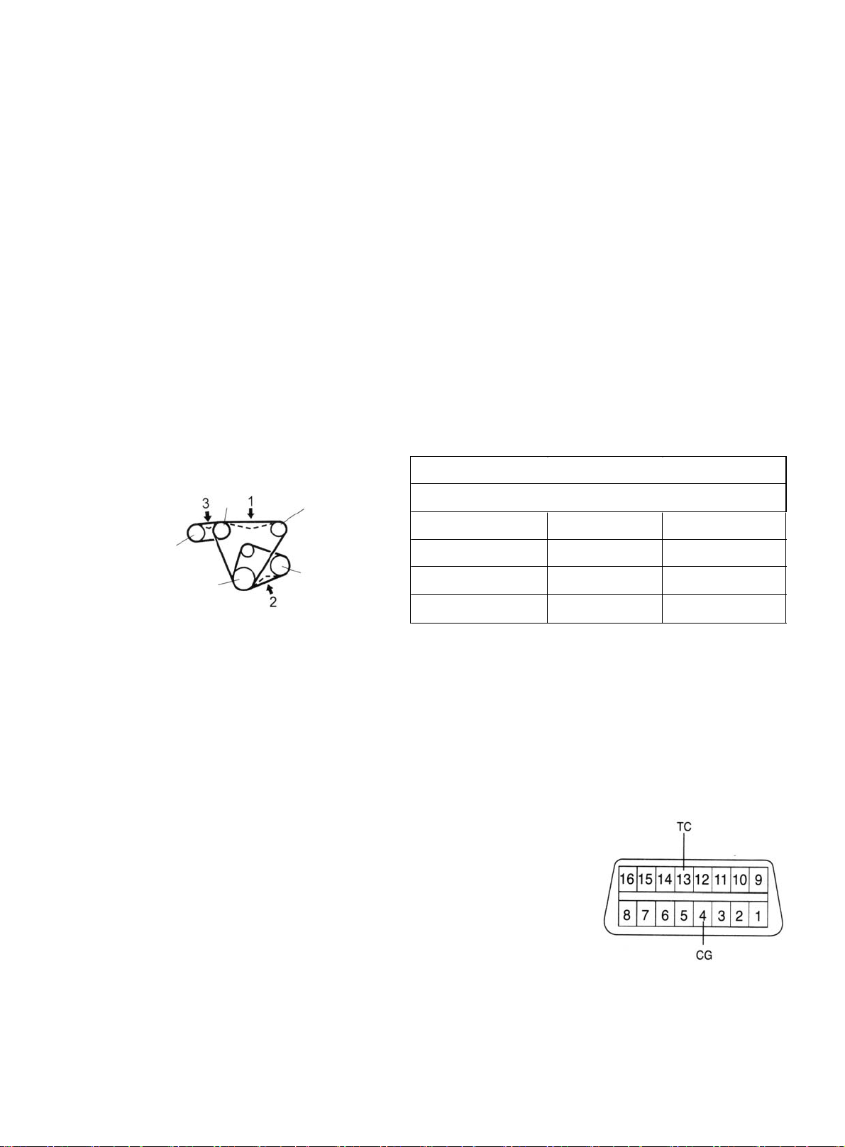
Belt Looseness
Notice:
Check the belt deflection at the specified point See (Figure 1).
z
Measuring Point
Figure 1
Air condition
compressor
Fan Belt 7
Power steering Belt 5~66
A/C Belt 6. 5~78
Belt deflection See (Table 1)
Belt pressure : 98N
New Belt mm Old Belt mm
~
9
11.5
~
~
~
13.5
8
9
z Set tension to specified value when installing new belt.
z Check the deflection to ensure it is below the specified value after the belt runs for over 5 minutes.
z Reinstall the belt which has been running for over 5 minutes. The deflection of the old belt is regarded as
the standard for inspection.
z Check V-belt for tension and distortion after the engine cranks for 2
turns.
7. Check ignition timing See (Figure 2)
a) Warm up the engine.
b) When using fault diagnosis tester
Connect fault diagnosis tester to fault diagnosis interface socket.
Ignition timing:
MR479Q: 10 ± 2° BTDC (before top dead center) at idle
MR479QA: 10 ± 2° BTDC at idle
MR481QA: 10 ± 2° BTDC at idle
Figure 2
1
Page 9
c) When fault diagnosis tester is not used
(1) Shorting fault diagnosis interface socket 13 (TC) terminal and 4(CG) terminal.
Notice:
z Ensure correct connection, otherwise the engine will be damaged.
z Switch off all electrical appliance system.
z Check when disconnecting cooling fan motor.
(2) Using timing light to check ignition timing.
Ignition timing: 10 ± 2° BTDC at idle
Notice:
(1) Transmission shift lever should be in neutral position when checking ignition timing.
(2) Running engine at 1,000-1,300rpm for 5s and check at idle.
(3) Remove the tester on fault diagnosis socket.
(4) Ignition timing advance angle becomes larger when the engine roate speed is higher.
(5) Remove timing light.
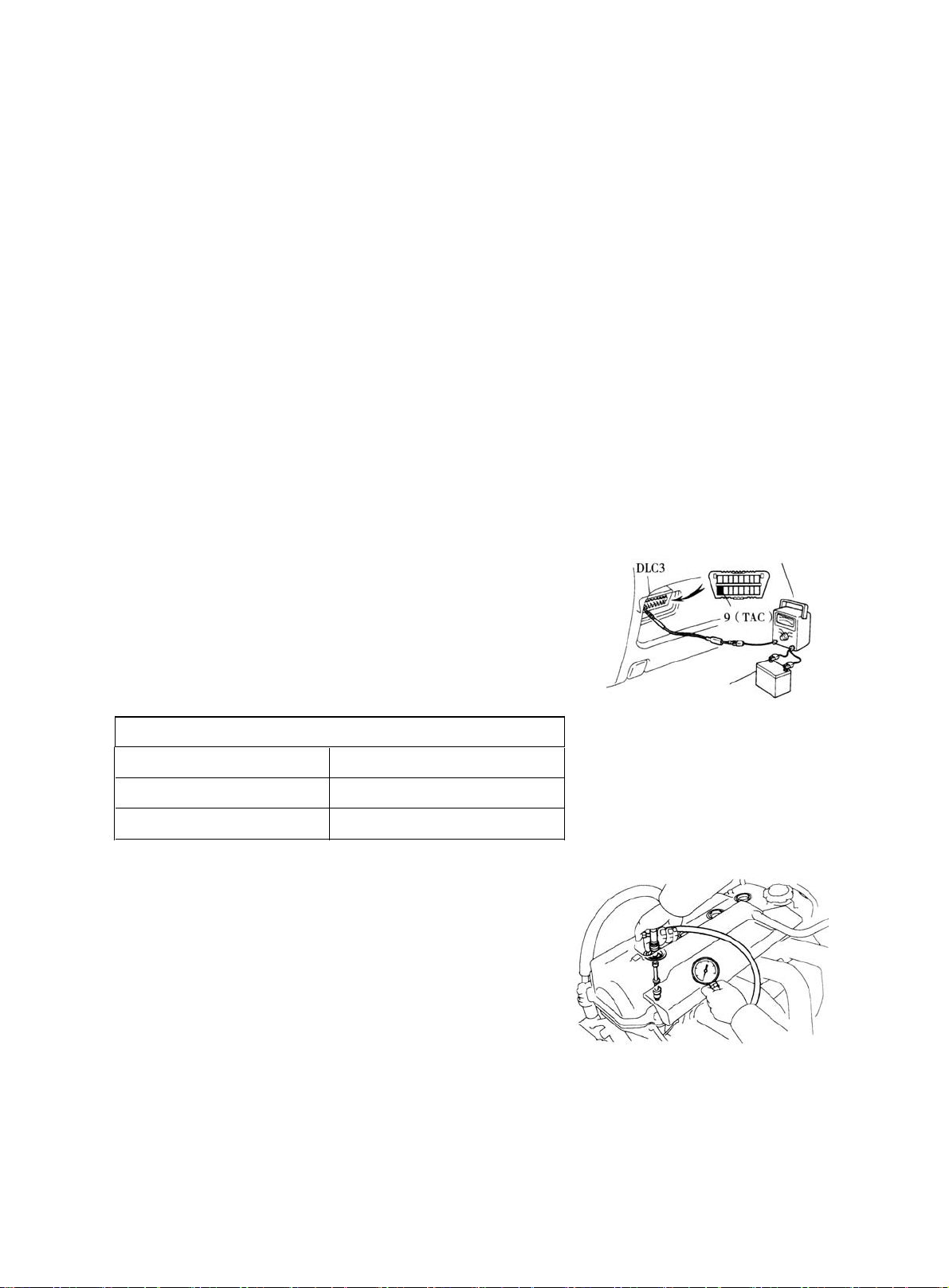
8. Check engine idle See (Figure 3)
(a) Warm up the engine.
(b) Connect fault diagnosis tester to fault diagnosis interface socket.
(c) Connect tachometer testing pen to fault diagnosis socket terminal
9 when not using fault tester.
(d) Check idle See (Table 2).
Table 2
MR479Q 800±50 (rpm)
MR4 79QA 800±50 (rpm)
MR 4 81QA 800±50 (rpm)
Notice:
z Check idle when cooling fan motor is disconnected.
Switch off all electrical accessories and A/C.
z
9. Check compression pressure See (Figure 4)
(a) Engine switched off.
Techometer
Battery
Figure 3
(b) Detach high voltage cable.
(c) Detach spark plug.
(d) Check the compression pressure in the cylinder.
(1) Insert pressure gauge into the hole of the spark plug.
(2) Throttle valve full open.
(3) Crank the engine, measure the compression pressure.
2
Figure 4
Page 10

The Min. compression pressure: 980 kPa
The tolerance range of the cylinders pressure: 100 kPa
Notice:
z
Ensure sufficient battery power and the engine speed is no less than 250 RPM (revolutions per minute).
z Check the compression pressure of other cylinders in the same way.
z Complete the measure as quick as possible.
(4) If the compression pressure in several cylinder is too low, fill some engine oil to the cylinder via the
hole of the spark plug. Check by repeating step 1-3.
Hint:
z If the compression pressure is improved after filling oil, the piston ring or the cylinder may be abrased
or damaged.
z If the pressure is still too low, the valve is stagnation or poor seal, or there is a leakage in gasket.
10. Check CO/HC
(a) Start engine.
(b) Running engine at 2500rpm for approximately 3 minutes.
(c) Insert CO/HC meter testing probe into tailpipe at least 40cm during idling.
(d) Check CO/HC concentration at idle and 2500rpm.
Hint:
Complete measurement within 3 minutes.
z
z Test the CO/HC emission concentration at idle and 2500 rpm on QC/T630-1999 standard.
(e) Take the following steps to diagnose the fault if the CO/HC concentration does not comply with standard .
(1) Check the oxygen sensor operation.
(2) See (Table 3) for the possible cause and check and repair.
3
Page 11
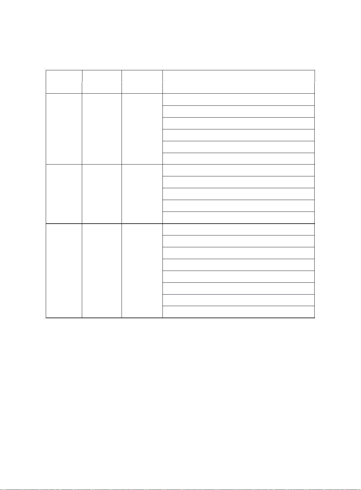
CO HC Problems Causes
1. F ault
. I ncorrect ignition timing
Table 3
Normal
Low High
High High
Rough idleHigh
Rough idle
Rough idle
(Bla c k smoke
from exhaust
pipe)
. Fouled, s hor t ed or improperly cle ara nce of spar k plug
2. Incorrect valve clearance
3. Leaky inta ke & exhaus t valves
4. Leaky cylinders
1. Air leaks
. PCV hoses, intake manifold
. Throttle body
. Brake booster circuit
2. L ean mixture gas caus ing misfire
1. Clogged air filter
2. C logged PCV valve
. Faulty ECU
. Faulty fuel pre ssure regula t or
. Faulty wa ter temperature sensor
. Faulty air compressor
. Faulty injectors
. Faulty throttle position sensor
4
Page 12
Section 2 Drive Belt Replacement
1. Disconnect all engine pipe hose and wire joint. Remove engine assembly from the engine
compartment, jack up the body, take out the engine assembly slowly (See Provision 20, Section
Two, Chapter Two for detailed information)
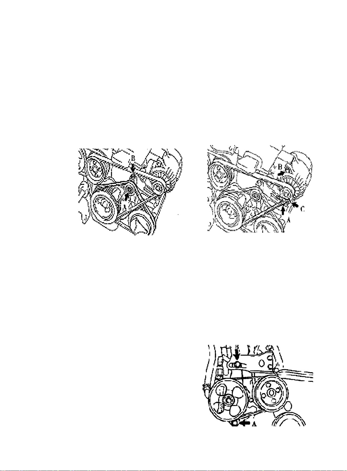
2. Remove generator V-belt See (Figure 5)
3. Remove No. 1 V-belt A/C compressor to crankshaft pulley
4. Remove water pump belt See (Figure 6)
5. Install water pump V-belt
6. Adjust V-belt of steering assisting pump
(a) Adjust power steering belt tension, tighten bolt B.
(b) Tighten bolt A.
Torque : 39N. m
7. Install V-belt A/C compressor No. 1 to crankshaft pulley
8. Adjust V-belt A/C compressor No. 1 to crankshaft pulley
(a) Adjust A/C belt tension by tightening bolt B.
(b) Tighten nut A.
Torque : 39N. m
9. Install Generator V-belt See (Figure 7)
10. Adjust Generator V-belt.
Tighten bolt A and then bolt B.
Figure 6Figure 5
Torque: Bolt A 18N. m Bolt B 58N. m
11. Check driving belt for distortion and tension
Figure 7
5
Page 13
Section 3 Valve Clearance Adjustment
1. Remove right camshaft timing gear
2. Remove ignition coil and high voltage cable
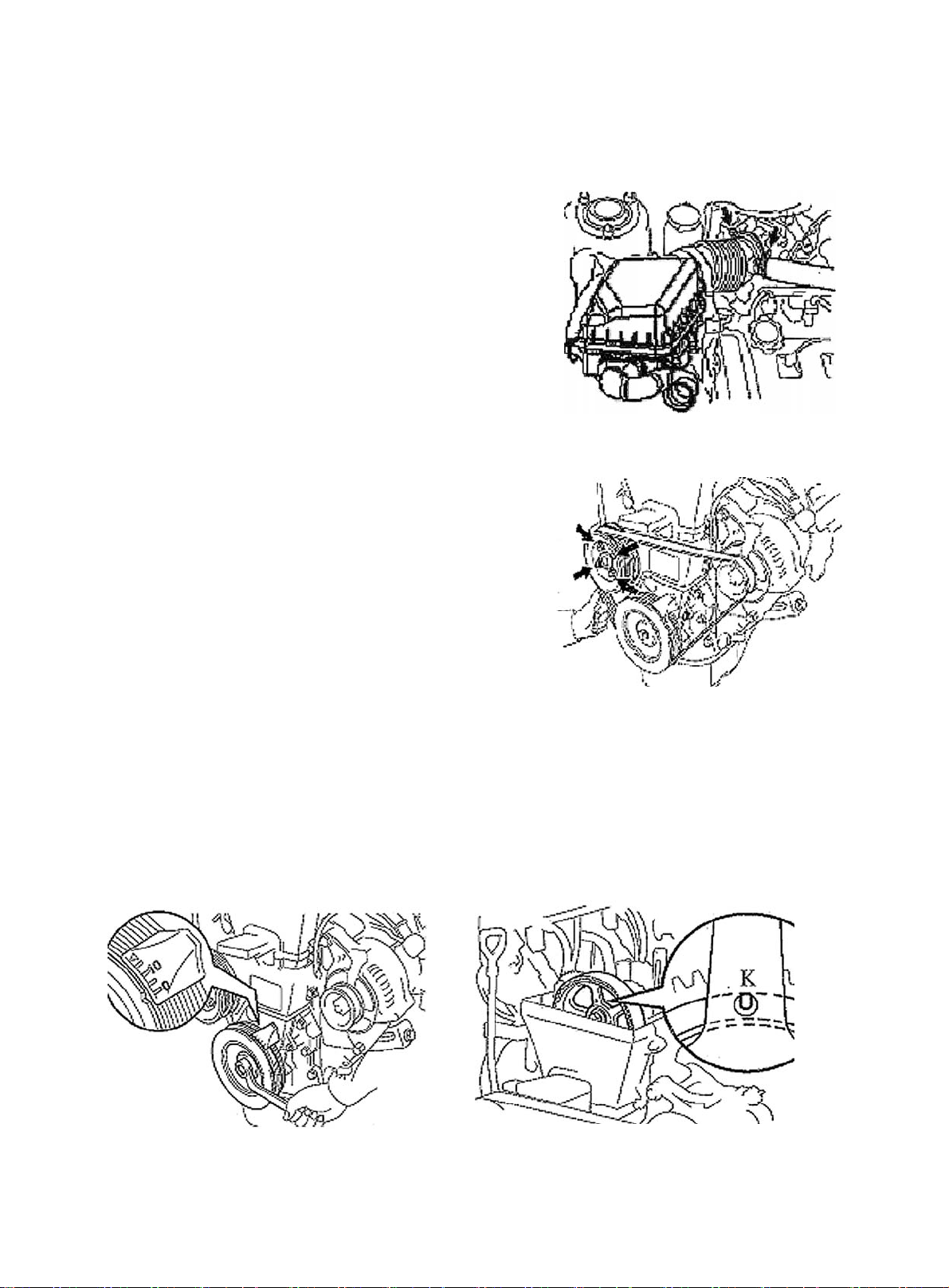
3. Remove cylinder head cover sub-assembly See (Figure 8)
(a) Disconnect generator wire joint..
(b) Disconnect generator circuit.
(c) Disconnect oil pressure switch connector.
(d) Disconnect A/C compressor switch connector.
(e) Open the wire harness clip.
(f) Remove wire harness from cylinder head cover.
(g) Separate 2 ventilation hoses from cylinder head cover.
(h) Remove 4 screw nuts, 4 oil seal gaskets, cylinder head and gasket.
4. Adjust piston of Cylinder 1 to the compression position
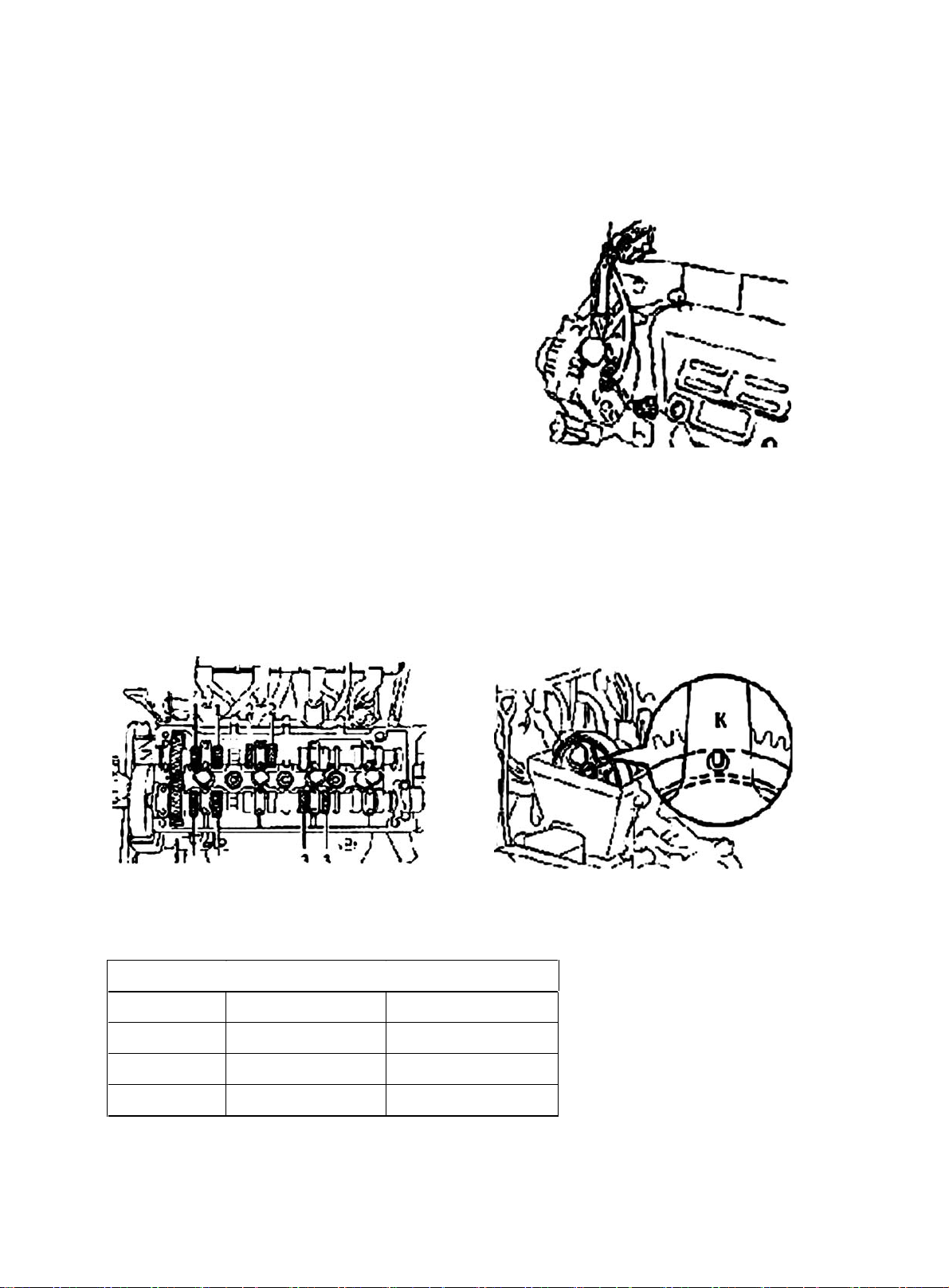
(a) Turn crankshaft pulley, align notch to timing mark "0" on Cylinder 1. See (Figure 9).
Figure 8
(b) Align mark "K" on camshaft timing pulley to the timing mark on bearing cap. See (Figure 10) Crank 360°
if it is not aligned.
Figure 9
5. Check valve clearance (cool). See (Table 5)
Table
5
Figure 10
Intake Valve mm Exha ust Valve mm
MR479Q 0.20 ± 0.05 0.30 ± 0.05
MR479Q A 0. 20 ± 0.05 0.30 ± 0.05
MR481Q A 0.20 ± 0.05 0.30 ± 0.05
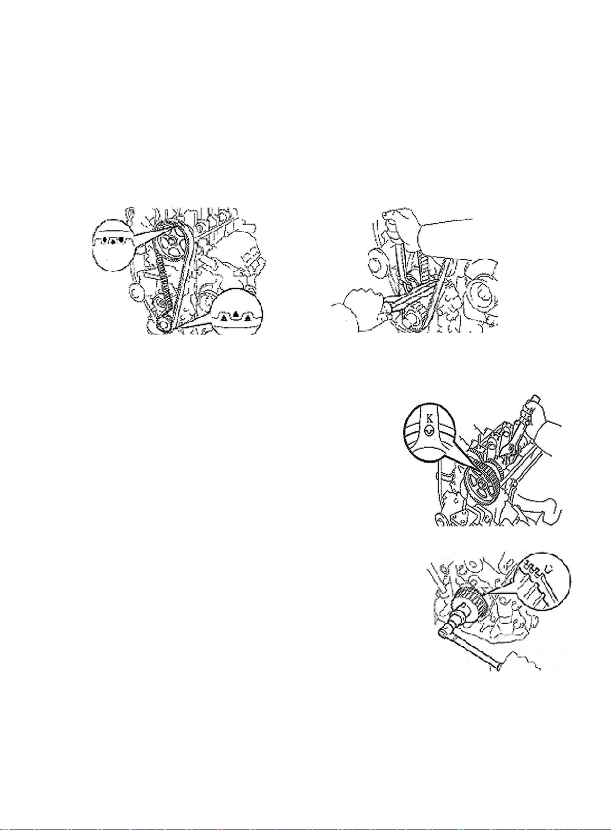
(a) Turn the crankshaft pulley for 360°. Align notch to timing mark "0" on timing belt cover No. 1.
(b) Only check the valve as shown in the figure. Valve clearance measurement. See (Figure 11).
6
Page 14
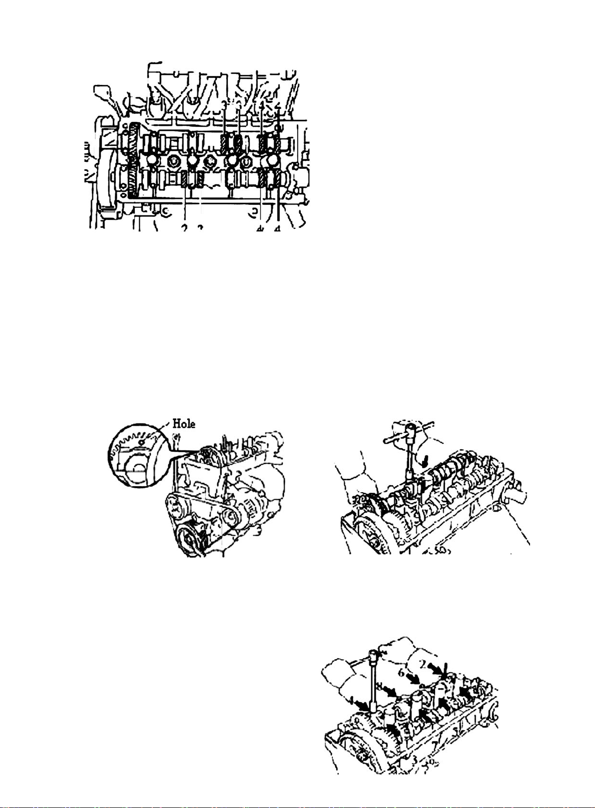
Figure 11
6. Adjust intake valve clearance
(a) Detach intake camshaft
Notice:
Because the camshaft end play is quite small, keep camshaft horizontal when removing it. If not, cylinder
head may be partially damaged by the thrust force£¬it may stuck or damage camshaft when turning crankshaft.
Take the following steps to avoid the damage:
(1) Turn the pulley to access the hole on the camshaft drive gear where the counter gear is installed. See
(Figure 12).
Hint:
The above condition allows the cylinders No. 1 and No. 3 of the intake camshaft to push up the valve tappet.
Figure 12
Figure 13
(2) Remove bolt and bearing cap No. 1.
(3) Install camshaft counter gear to drive gear with service bolt. See (Figure 13).
(4) Uniformly loose and remove 8 bearing cap bolts in several passes as
shown in the figure. See (Figure 14).
(5) Remove 4 bearing caps and camshafts.
Figure 14
7
Page 15
Notice:
Due to the small end play on camshaft, the cylinder head may be damaged by the thrust force when removing
it, it may stuck or damage camshaft. Take the following steps to avoid damage:
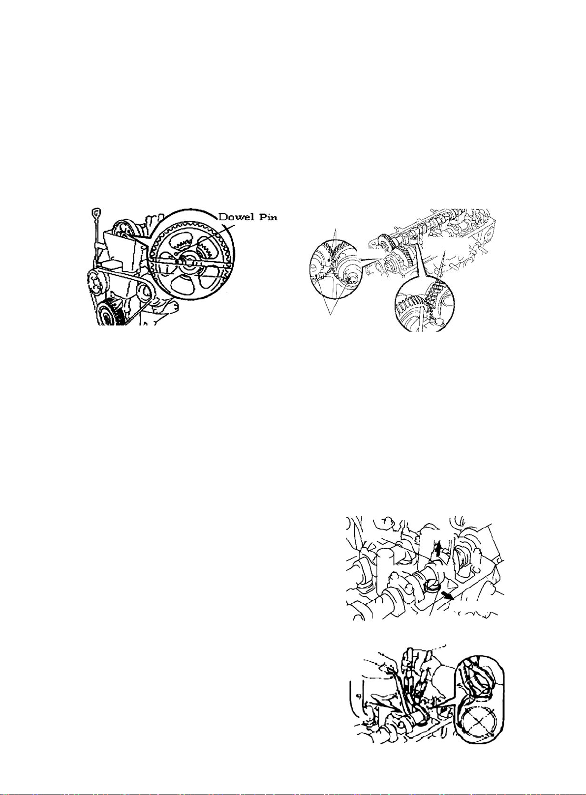
(1) Turn the crankshaft pulley to make exhaust camshaft dowel pin is a bit higher than the cylinder head. See
(Figure 15).
(2) Align the matchmark on each gear to engage intake camshaft gear and exhaust camshaft gear. See
(Figure 16).
(3) When the gears are engaged, install the intake camshaft bearing onto bearing journal.
Install Mark
March Mark
Timing Mark
Figure 15
Figure 16
Hint:
The intake camshaft lobe of cylinder 1 and 3 can jack up their own valve tappet.
(5) Install 4 bearing caps to the right position.
(6) Apply a light layer of engine oil on the thread and under the head of bearing cap bolts.
(7) Uniformly install and tighten 8 bearing cap bolts in several times, in the sequence shown in the figure.
Torque: 13N. m
(8) Remove service screw.
(9) Install the bearing cap No. 1. in the direction of the forward arrow mark.
(10)Apply a light layer of engine oil on the thread and under the head of bearing cap bolts.
(11)Alternatively tighten and install 2 bearing bolts.
Torque: 13N. m
Cam Lobe
Upward
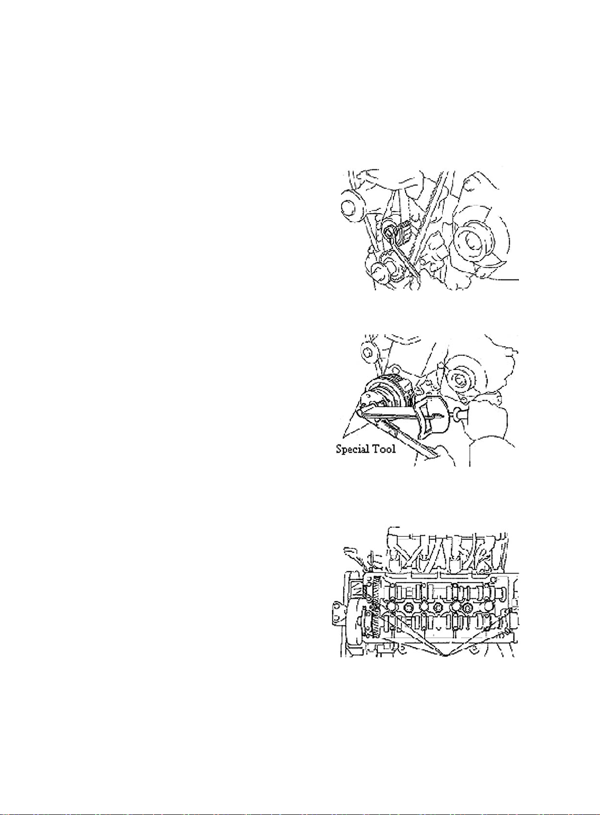
7. Adjust exhaust valve clearance. See (Figure 17)
Remove adjust gasket.
Front
(1) Crank to keep the camshaft head upward.
Nick
(2) Face valve tappet nick to vehicle front.
(3) Press valve tappet, put special tool between camshaft and valve tappet.
Figure 17
Hint:
z Lean the end with mark "9" into the position in (Figure 18).
8
Figure 18
Page 16
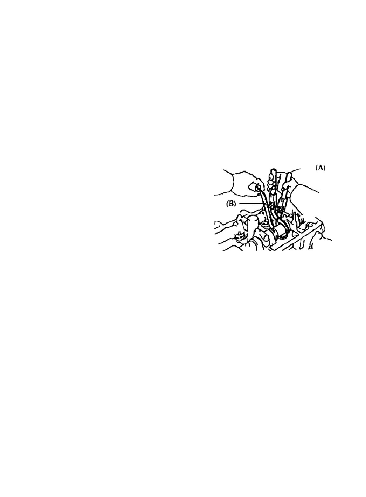
(4) Alternatively press valve tappet with the special tool (A) (B). Check
valve clearance. See (Figure 19).
8. Install cylinder head sub-assembly
(a) Remove all old gasket material.
(b) Apply the seal glue to the cylinder head.
(c) Connect wire harness and clip.
(d) Install gasket under of cylinder head.
(e) Install the cylinder head cover with 4 seal gaskets and 4 screw caps.
T orque: 7.8N. m
(f) Install 2 ventilation hoses to cylinder head cover.
(g) Connect generator wire joint.
(h) Connect generator wires.
(i) Connect oil pressure switch connector.
(j) Install wire clip.
(k) Connect A/C compressor switch connector.
9. Install electronic ignition coil and high voltage cable
10. Check engine oil for leakage
Figure 19
9
Page 17
Chapter 2 Engine Components Replacement
(MR479Q, MR479QA, MR481QA)
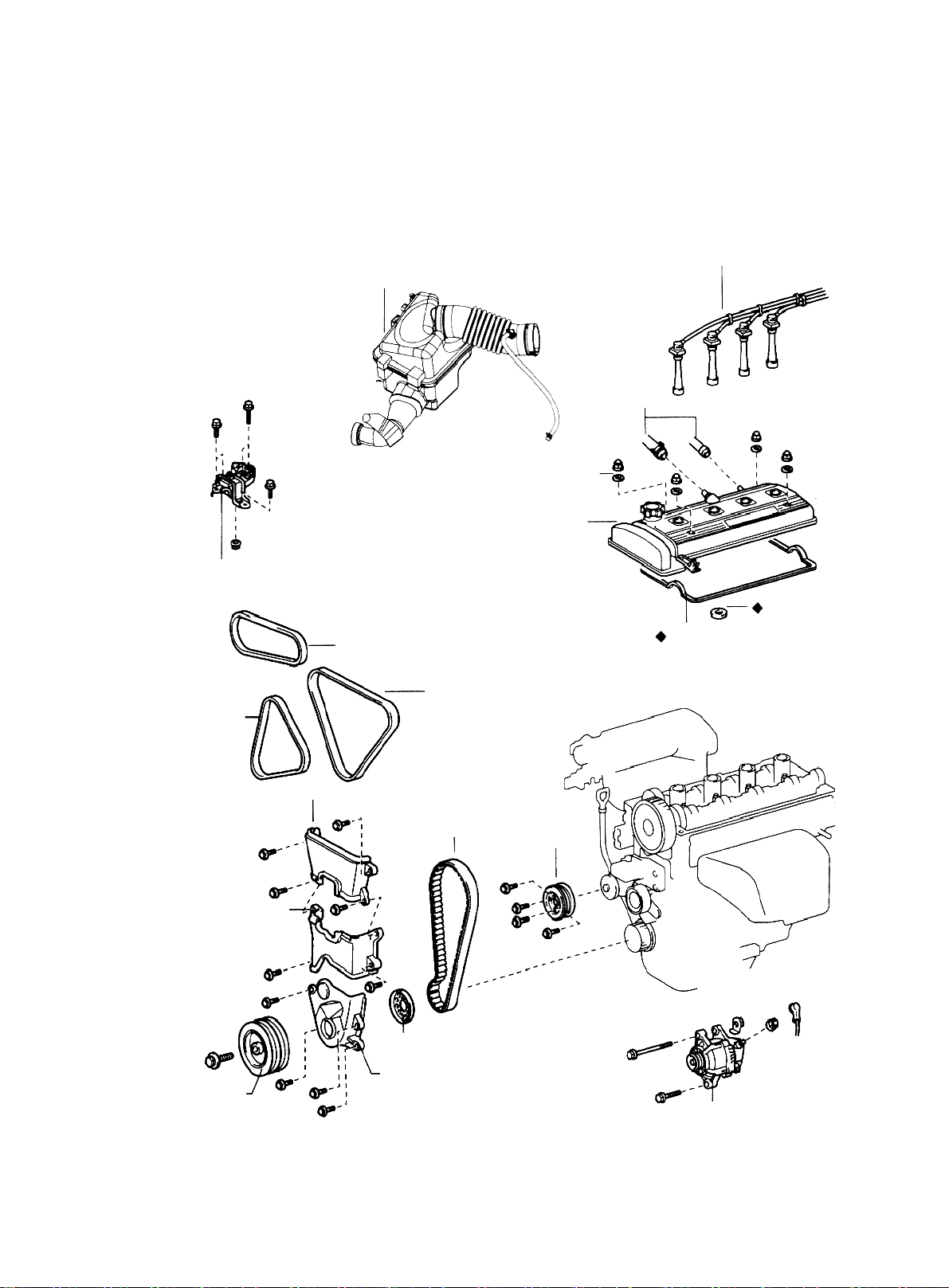
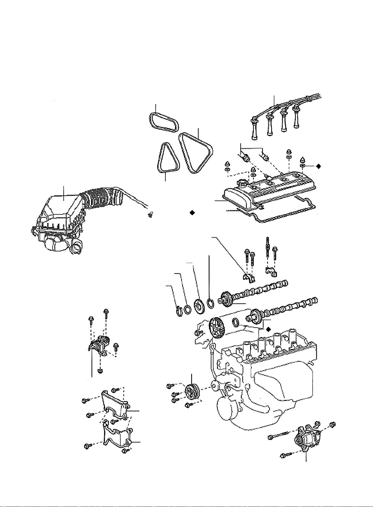
Section 1 Engine Components
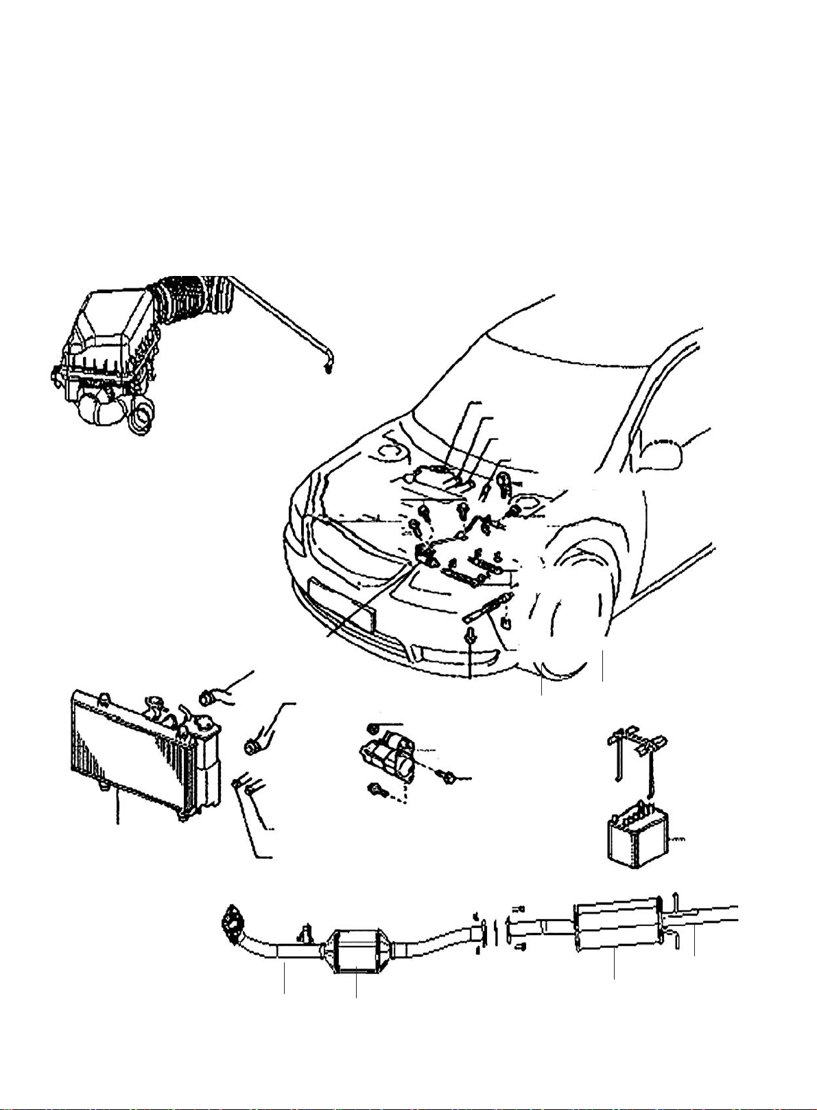
Component 1
Air Filter Assembly W/ Hose
Accelerator Control
Cable Assembly
Heater Inlet Hose
Heater Outlet Hose
Fuel Sub-Assembly
Efi Fuel Pipe Clamp
Radiator Assembly
MT:
Clutch Release
Cylinder Assembly
Radiator Inlet Pipe
AT: Oil Cooler
AT: Oil Cooler
Outlet
Pipe
Inlet
Pipe
Radiator Outlet Pipe
Starter Assembly
MT:
Transmission
Control Cable
Assembly
AT:
Transmission Control Cable Assembly
Battery
10
Front Exhaust
Pipe Assy.
Tail Pipe
Muffler
3-way catalytic
converter
Figure 20
Page 18
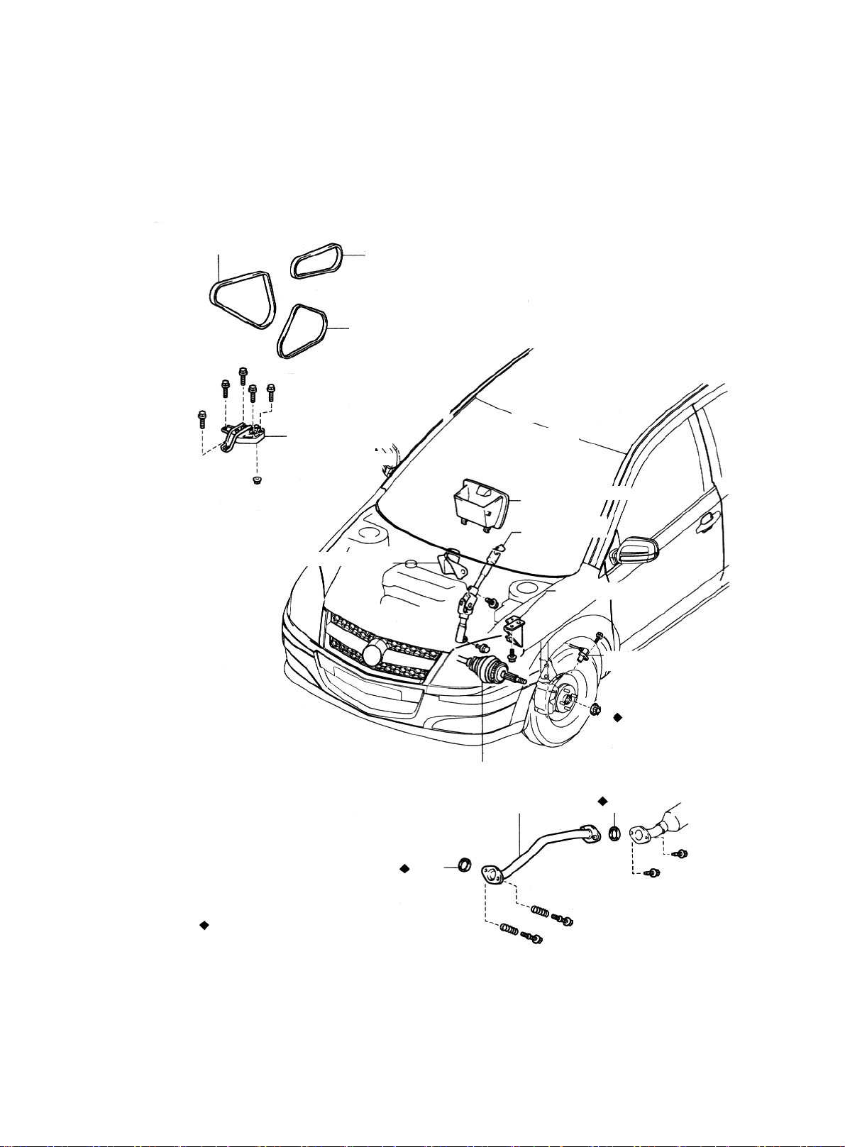
Component 2
Fan & Generator V-Belt
Vane-Type Pump V-Belt (V/ Power Steering)
V-Belt No.1
Right Engine
Glove Compartment
Steering Column
Hole Cover
Mounting Insulator
Door Assembly
Steering Column
Assembly
Steering Column Hole Cover
One-off accessory
Front Shaft Hub Left Nut
Front exhauxt pipe assembly
Gasket
Figure 21
Left Engine Mounting Bracket
Left Front Speed Sensor
Gasket
11
Page 19
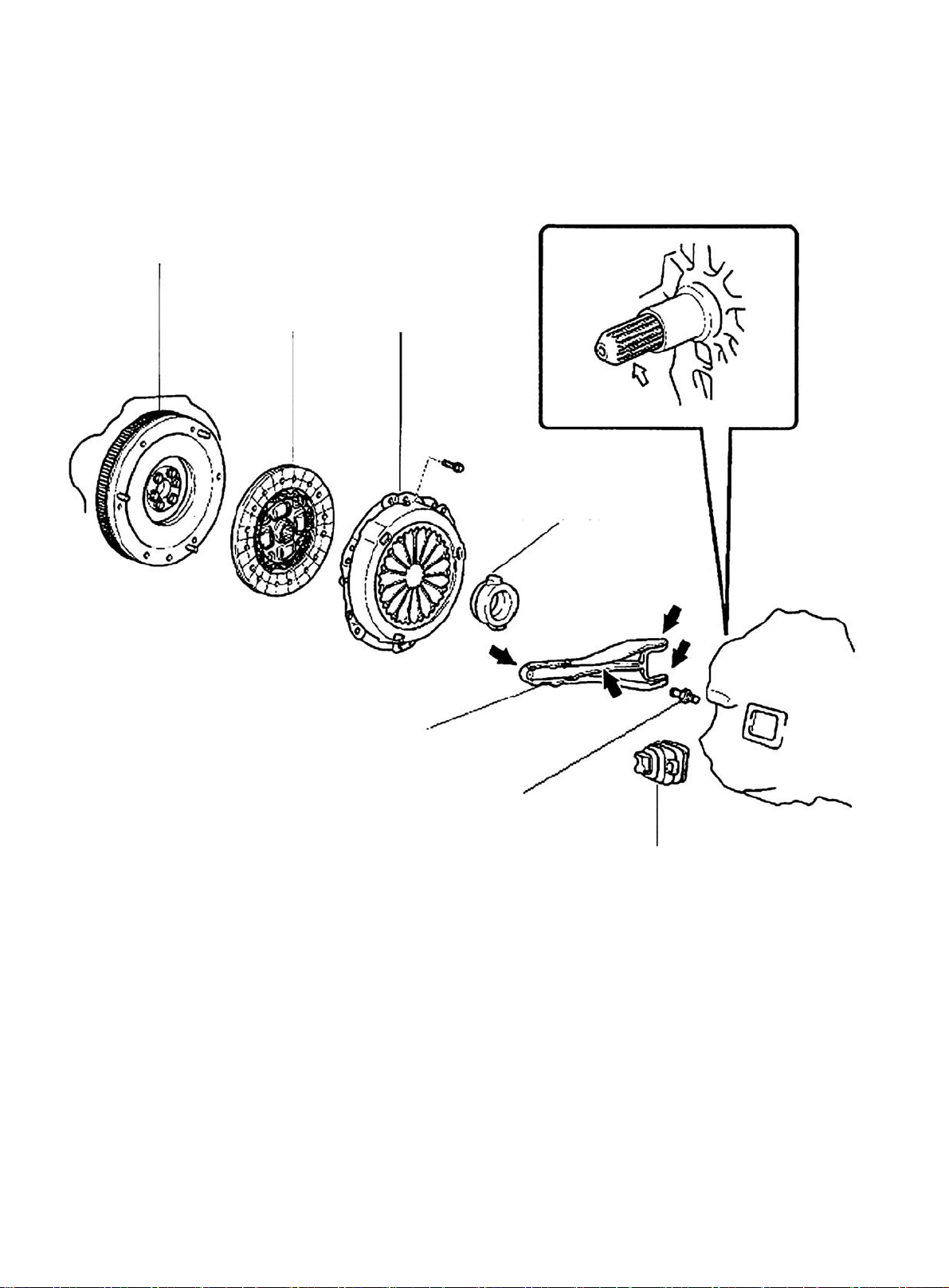
Flywheel
Component 3
Clutch Disc
Clutch Release Fork
Clutch Cover
Clutch Release Bearing
12
Release Fork Support
Release Fork Boot
Figure 22
Page 20
Section 2 Engine Components Replacement
1. Avoid gasoline ejection when work.
2. Drain the coolant to empty.
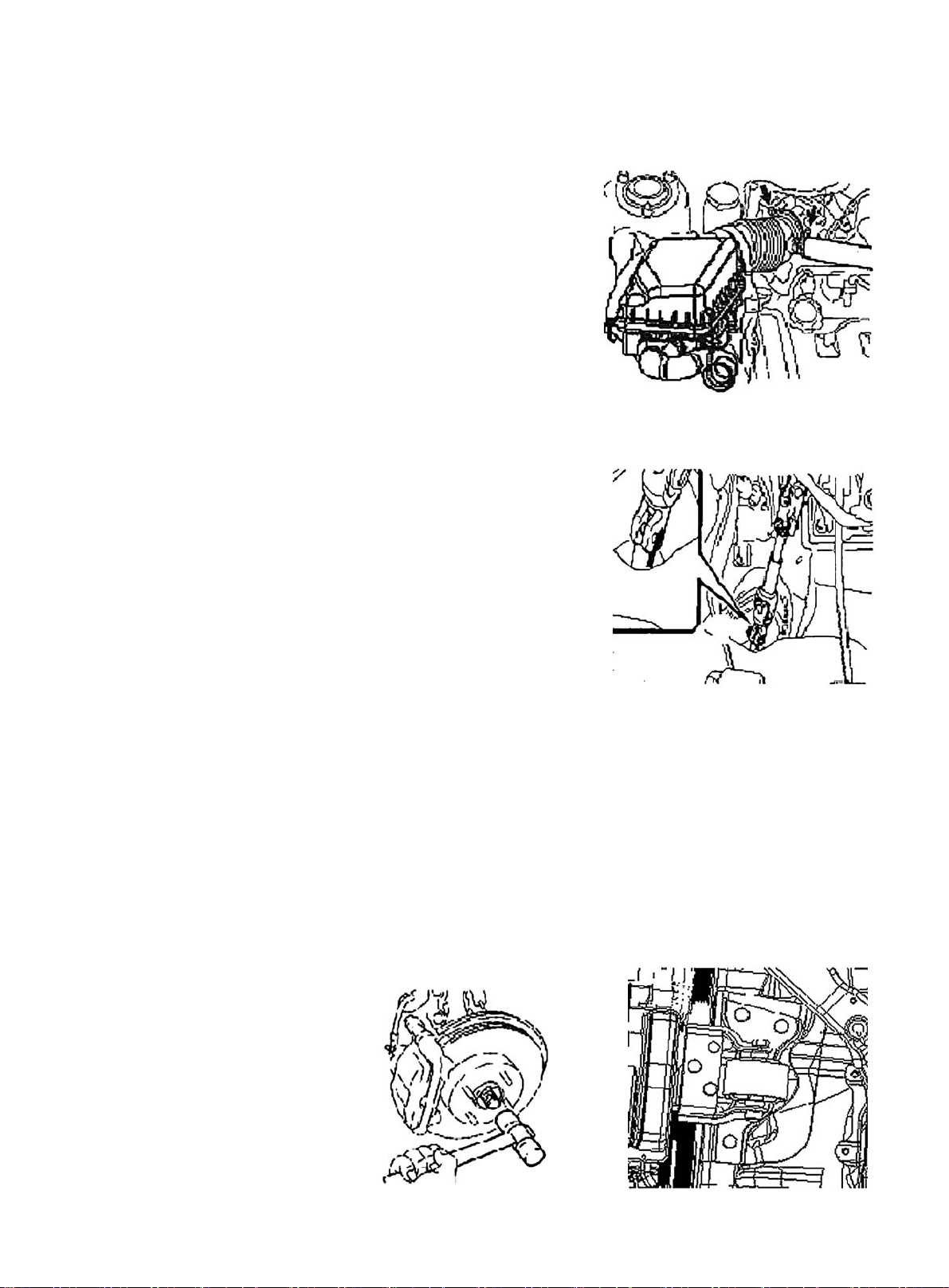
3. Remove air filter assembly with hose. See (Figure 23)
4. Remove battery
5. Remove fuel delivery pipe sub-assembly
6. Disconnect water hoses, disconnect heater outlet hose
from A/C hose.
7. Loose nut, remove accelerator control cable
8. Remove throttle body assembly
9. Remove power steering pump reservoir assembly
10. Remove front exhaust pipe assembly
11. Remove steering gear boot
12. Seperate steering column assembly. See (Figure 24)
13. Remove front wheel hub nut
Figure 23
14. Disconnect front wheel vehicle speed sensor (with ABS)
15. Detach steering tie rod ball stud pin assembly
16. Detach front lower swing arm sub-assembly
17. Detach front propeller assembly. See (Figure 25)
Detach front propeller from the shaft hub with plastic hammer.
18. Disconnect transmission shift cable or gear shift level assembly
19. Disconnect clutch cylinder assembly or disconnect clutch cable
20. Detach engine assembly and transaxle
(a) Hoisting engine ;
(b) Remove 3 bolts. Detach the right engine mounting bracket. See (Figure 26) ;
(c) Remove 1 bolt. Detach the left engine mounting bracket;
(d) Remove 1 bolt. Detach the rear engine mounting bracket;
(e) Remove engine and transaxle and put them on the pallet;
(f) Jack up the boday.
Figure 24
Figure 25 Figure 26
13
Page 21
21. Remove radiator assembly
22. Remove engine V-belt
23. Remove No. 1 V- belt (A/C compressor to crankshaft pulley)
24. Remove generator assembly
25. Remove A/C compressor
26. Remove compressor installing No. 1 bracket. Remove 4 bolts and compressor installing No.
1 bracket.
27. Remove starter assembly
28. Remove power steering pump V- belt
29. Detach power steering pump assembly
30. Remove power steering pump, adjust the bracket
31. Detach manual transaxle assembly (Separate automatic transaxle assembly)
32. Detach clutch cover panel assembly.
33. Detach clutch pressure plate assembly.
34. Detach flywheel sub-assembly.
35. Remove engine rear end cover.
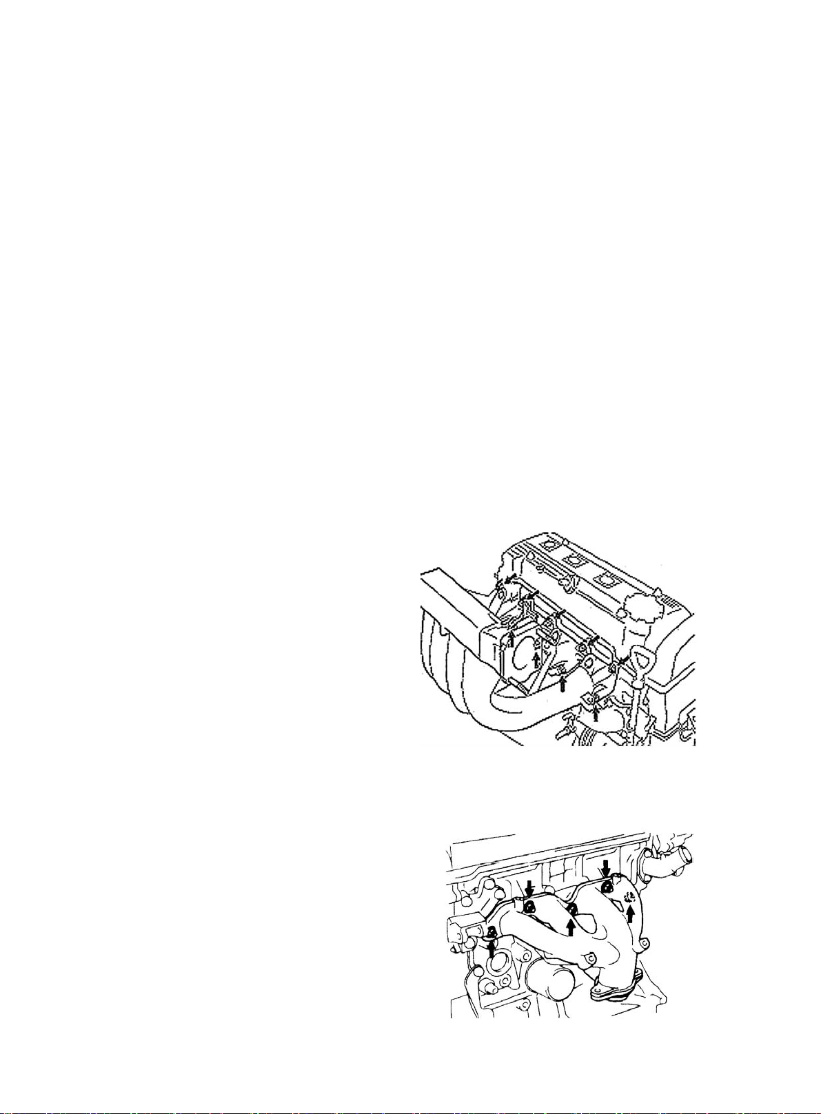
36. Remove injector assembly and remove intake manifold.
Remove 2 bolts and intake manifold support and remove 7 bolts,
2 nuts, intake manifold and gasket. See (Figure 27).
37. Remove knock sensor
38. Remove water temperature gauge sensor
39. Remove crankshaft position sensor
40. Remove engine oil pressure switch
41. Remove water inlet hose housing
42. Remove water outlet hose joint
43. Detach exhaust manifold. See (Figure 28)
44. Remove engion oil filter sub-assembly
45. Remove ignition coil and high voltage cable
46. Install engine sub-assembly
47. Install ignition coil and high voltage cable
48. Install engine oil filter sub-assembly
49. Install exhaust manifold
Figure 27
(a) Install new gasket and exhaust manifold stay with
5 nuts, Torque: 34N. m
(b) Install exhaust manifold stay with two bolts.
Torque: 59N. m
(c) Install upper heat shield with 4 bolts.
14
Torque: 17N. m
Figure 28
Page 22
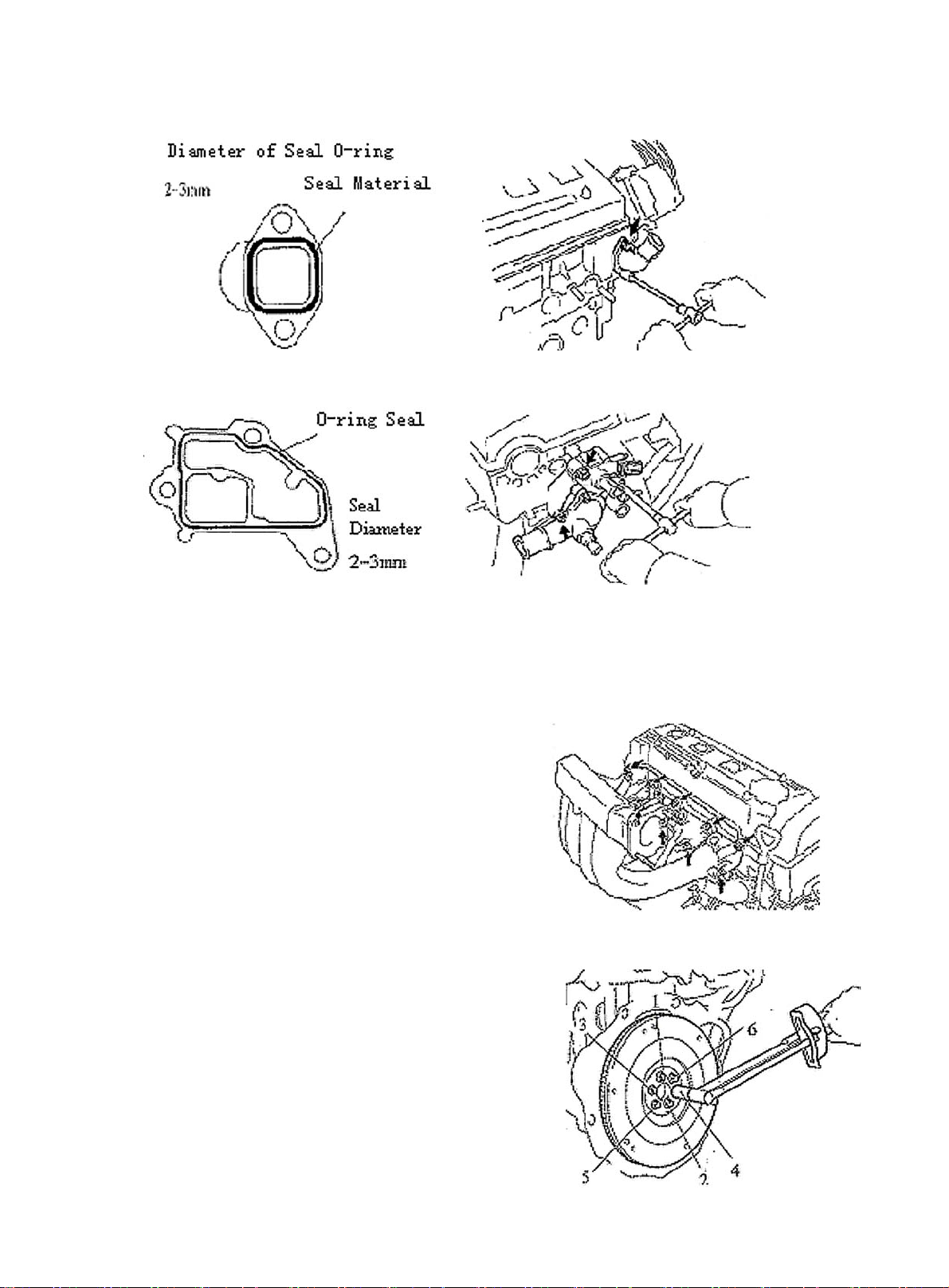
50. Install water outlet hose joint. See (Figure 29, 30)
Figure 29
Figure 30
51. Install water inlet hose housing. See (Figure 31, 32)
Figure 31 Figure 32
52. Install engine oil pressure switch
53. Install crankshaft position sensor
T orque: 9, 3N. m
54. Install water temperature gauge and water temperature sensor
T orque: 15N. m
55. Install knock sensor
Torque: 44N. M
56. Install intake manifold. See (Figure 33)
Install the intake manifold with new gasket with 7 bolts and 2
nuts. Uniformly tighten bolts and nuts in several time.
57. Install injector assembly
58. Install rear end cover
59. Install flywheel sub-assembly. See (Figure 34)
(a) Install flywheel to crankshaft.
(b)Install and uniformly tighten and connect bolt as shown in the
figure. Torque: 78N. m
60. Install clutch assembly
61. Install flywheel and ring gear. See (Figure 35)
(a)Install the oil thrower, it’s chamfer side on crankshaft in
the axie direction.
(b) Install flywheel and ring gear on crankshaft.
Figure 33
Figure 34
15
Page 23
(c) Install and uniformly tighten connecting bolt in the sequence shown in
the figure.
Torque: 64N. m
62. Install manual transaxle assembly
63. Install starter assembly
64. Install power steering pump bracket
65. Install power steering pump adjusting bracket with 2 bolts.
66. Connect power steering pump assembly
67. Install engine assembly and transaxle
68. Connect left, right, front and rear lower suspension arm sub-assembly
69. Connect left and right tie rod ball stud pin assembly
70. Connect left, right and front vehicle speed sensor (with ABS)
71. Install left & right nuts on the front shaft hub
72. Install front exhaust pipe assembly
73. Connect steering shaft assembly and steering column hole cover. See (Figure 36)
74. Connect wire harness
75. Install belt adjusting bracket of A/C compressor
76. Connect A/C compressor
77. Install generator assembly
78. Install A/C compressor to crankshaft pulleyV-belt
79. Install generator belt
80. Install engine assembly with transaxle
81. Install radiator assembly
82. Install throttle body assembly
83. Install fuel delivery pipe sub-assembly
84. Install battery
85. Install air filter assembly with hose
86. Install front wheel
87. Fill engine oil
88. Fill coolant
89. Check engine oil for leakage
90. Check engine coolant for leakage
Figure 35
91. Check fuel for leakage
92. Check idle and ignition timing
93. Check CO/HC
94. Check and adjust front wheel alignment
95. Check ABS vehicle speed sensor signal
16
Figure 36
Page 24
Right Engine Mounting
Section 3 Timing Belt Replacement
Air Filter Assembly W/ Hose
Ventilation Pipe
Seal
Cylinder Head
Vane-Type Pump V-Belt V/ Power Steering
Cylinder Head Gasket
High Pressure Cable
Gasket
V-Belt No.1
Timing Chain Or Timing Belt Cover Assembly No. 2
Crankshaft Or Pulley
Cover Sub-Assembly
Timing Chain Timing Belt
Crankshaft Pulley
Cover Sub-Assembly
Fan & Generator V-Belt
Timing Belt
Timing Belt Guide
Fan Pulley
Generator Assembly
Figure 37
17
Page 25
1. Disconnect engine from all the wire harnesses and cables connected to body.
2. Remove air filter assembly with hose. See (Figure 38)
3. Disconnect oil pipe and water hoses
4. Loose positive and negative cables on battery
5. Detach propeller shaft
6. Loose engine left & right rear brackets after hoisting engine
7. Disconnect all the connectors of engine and the body
8. Remove engine per "Provision 20, Section 2, Chapter 2"
9. Remove A/C compressor to crankshaft pulley V-belt
10. Remove power steering pump V-belt
11. Remove water pump fan pulley
12. Remove high pressure cable.
13. Remove cylinder head cover sub-assembly
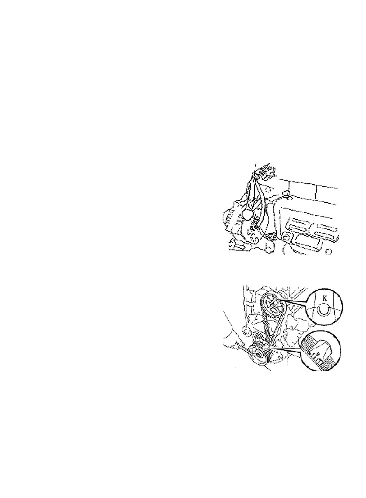
14. Remove generator assembly. See (Figure 39)
15. Put the piston in Cylinder 1 to TDC compression position
(a)Turn crankshaft pulley to align its notch to the timing mark "0"
on the timing belt cover. See (Figure 40).
(b) Check if the "K" mark on camshaft timing pulley and the timing mark
on the bearing cap are aligned. Crank the crankshaft for 360 degrees
if not. See (Figure 41).
16. Remove crankshaft pulley
17. Remove timing belt cover
18. Remove crankshaft gear or pulley cover sub-assembly
19. Remove timing belt cover sub-assembly
Figure 38
Figure 39
18
Figure 40
Figure 41
Page 26
20. Remove timing belt guide wheel
Hint:
(a) Mark on pulley and belt (in engine turning direction) if re-using timing belt (See Figure 42).
(b) Install bolt to the idler pulley. Move pulley to its far left and tighten it temperarily (See Figure 43).
21. Remove spark plug and gasket
Figure 42
22. Install spark plug and gasket
23. Put the piston in Cylinder 1 to TDC compression position.
See (Figure 44)
(a) Turn camshaft hexagon part. Align the mark "K" on the camshaft
timing pulley to the mark on the bearing cap.
(b) Using the crankshaft pulley bolt, turn the crankshaft, align the mark
on crankshaft timing pulley to the oil pump.
24. Install timing belt. See (Figure 45)
Notice: The engine must be cool.
(a) Install timing belt. Check the tension force between crankshaft timing
pulley and camshaft timing pulley.
Hint: Align the marks if re-using the timing belt when removing. The
engine's rotating direction should be the same with the arrow's when
installing belt.
Figure 43
Figure 44
(b) Check valve timing. Loose idler bolt.
(1) Turn crankshaft from TDC to BDC slowly.
Notice: Crank always in clockwise.
Figure 45
(2) Align each pulley to timing mark as shown in the figure. If the timing mark is not aligned,
remove timing belt and reinstall it.
(3) Tighten idler bolt.
T orque: 37N. m
(4) Remove crankshaft pulley bolt.
19
Page 27
(c) Check timing belt for deflection
Check the belt distorn as shown in the figure.
Belt deflection:
20N: 5~6mm
Re-adjust the idler if the deflection does not comply with the regulation.
25. Install timing belt guide wheel. See (Figure 46)
Install guide, place the cup side outward.
26. Install timing belt cover sub-assembly
Torque: 9.3N. m
27. Install crankshaft gear or pulley cover sub-assembly
Torque: 9.3N. m
28. Install timing belt cover
Torque: 9.3N. m
29. Install crankshaft pulley. See (Figure 47)
(a) Align pulley lock key and pulley key groove. Install pulley .
Figure 46
(b) Install pulley bolt T orque: 127N. M
30. Install generator assembly
31. Install water pump pulley
32. Install power steering pump V-belt
33. Install A/C compressor fan to crankshaft pulleyV-belt
34. Install cylinder head cover sub-assembly.
(a) Wipe off all seal packing material.
(b) Apply the seal glue on cylinder head cover as shown in Figure 48.
(c) Install gasket onto cylinder head cover.
(d) Install cylinder head cover with 4 seal gaskets and 4 nuts.
Torque: 7.8N. M
(e) Install 2 ventilation hoses onto cylinder head cover.
(f) Install engine wire harness onto cylinder head cover.
(g) Connect generator wire joint.
(h) Connect generator wire.
Figure 47
(i) Connect oil pressure switch connector.
(j) Install wire clip.
(k) Connect A/C compressor switch connector.
35. Hoist the engine back into the compartment
36. Install left & right rear engine mounting brackets
37. Install ignition coil and high pressure cable
38. Install air filter assembly with hose
20
Figure 48
Page 28

39. Install oil pipe and water hose
40. Install left & right propeller shaft
41. Install left & right front wheel
42. Check engine oil for leakage
43. Install all connected wire harnesses and the cables on engine and vehicle body
21
Page 29
Section 4 Camshaft Replacement
Air Filter Assembly W/ Hose
Vane-Type Pump V-Belt
V/ Power Steering
Fan & Generator V-Belt
V-Belt No.1
Cylinder Head
Crankshaft Bearing Cap
Crankshaft Timing Belt Washer
Crankshaft Counter Gear
Wave Gasket
Ventilation Pipe
Cylinder
Head Gasket
High Pressure Cable
Seal
Right Engine Mounting
Snap Ring
Camshaft Timing Pulley
Fan Pulley
Timing Belt
Cover No. 2
Crankshaft Or Pulley
Cover Sub-Assembly
Figure 49
Camshaft
Camshaft No. 2
Oil Seal
Generator Assembly
22
Page 30
1. Disconnect all connected wire harnesses and the cable on the engine and the vehicle body
2. Remove air filter assembly with hose
3. Disconnect oil pipe and water hose
4. Loose positive and negative cables of the battery
5. Detach propeller shaft
6. Loose left & right rear engine mounting bracket after hoisting the engine.
7. Disconnect all other connectors between the engine and the vehicle body.
8. Remove engine per "Provison 20, Section 2, Chapter 2"
9. Remove A/C compressor to crankshaft pulleyV-belt
10. Remove power steering pump V- belt
11. Remove water pump fan pulley
12. Disconnect ignition coil and high voltage cables
13. Remove cylinder head cover sub-assembly
14. Remove generator assembly
15. Remove cylinder head cover sub-assembly
(a) Disconnect generator wire joint.
(b) Disconnect generator circuit
(c) Disconnect A/C compressor switch connector.
(e) Open wires clips.
(f) Disconnect wire harness from the cylinder head cover.
(g) Disconnect 2 ventilation PCV hoses from cylinder head cover.
(h) Remove 4 screws, 4 seal gaskets, cylinder head and gasket.
16. Remove generator assembly. See (Figure 50)
17. Remove timing belt cover
18. Remove crankshaft gear or pulley cover sub-assembly
19. Put the piston on Cylinder 1 to TDC compression position.
(a) Turn crankshaft pulley. Align its notch to the timing mark "O" on the
timing belt cover.
(b) Check if the mark "K" on camshaft timing pulley is aligned to the
timing mark on the bearing cap. Turn crankshaft 360° if not.
20. Remove ignition coil assembly
Figure 50
Figure 51
21. Remove timing belt. See (Figure 51)
(a) Mark on the timing belt and the camshaft pulley. The mark on the
timing belt to the timing belt cover No. 1 should match.
(b) Remove rubber gasket from timing belt cover.
23
Page 31

(c) Loose installing bolt of the idler. See (Figure 52). Move the pulley to
its far left and tighten it temporarily.
(d) Remove the belt from the camshaft timing pulley.
Notice:
z Hold the timing belt, the engagement of the crankshaft timing
pulley and timing belt will not move.
z Be careful not to drop anything into the timing belt cover.
z Do not let the belt contact oils, water or dirt.
Figure 52
Figure 53
22. Remove the camshaft and the timing pulley. See (Figure 53)
(a) Turn the camshaft hexagon head and loose pulley bolt.
(b) Remove pulley bolt and timing pulley.
23. Remove camshaft. See (Figure 54)
Because the camshaft end play is quite small, keep camshaft horizontal
when removing it.Take the following steps to avoid the damage:
(a) Remove the camshaft
(1) Turn the camshaft to access the hole of the counter gear installed on camshaft drive gear.
Hint: The intake camshaft lobe of Cylinder 1 and 3 can push up their
own valve tappet.
(2) Remove 2 bolts and bearing cap No. 1.
(3) Install the counter gear on the intake camshaft with the service
bolt onto the drive gear.
(4) Uniformly loose and detach 8 bearing cap bolts in several times
in the sequence shown in Figure 55.
Figure 54
Figure 55
(5) Remove 4 bearing caps and camshaft.
If the camshaft can not be kept horizontal, lift it vertically. Reinstall the
bearing cap with 2 bolts. Alternatively loose and detach the bearing cap
bolts and lift the camshaft gear. See (Figure 56)
24
Figure 56
Page 32

(b) Remove the counter gear of the camshaft.
(1) Clamp the camshaft's hexagon on the vise.
(2) Turn the counter gear cloclwise, Remove the service bolt.
(3) Remove the snap ring with a circlip pliers. See (Figure 57).
(4) Remove waved gasket, camshaft counter gear and the camshaft gear spring. See (Figure 58)
24. Remove and install spark plug hole gasket. See Provision 15 and 16, Section 3 Timing Belt
Replacement for detailed information. See (Figure 44, 45).
Rotate
Figure 57
Figure 58
25. Install camshaft
(a) Install exhaust camshaft and turn camshaft counterclockwise to make the dowel pin cross the vertical
line a little. See (Figure 59).
(b) Apply grease to a new oil seal lip and install it into the oil seal. See (Figure 60).
Figure 59
Figure 60
(c) Install camshaft counter gear.
Figrue 61
(1) Clamp the camshaft's hexagon head with a vise.
(2) Install camshaft gear spring, camshaft counter gear and waved washer. (Figure 61).
Hint: Align the pin on the gear to the spring end of the counter gear.
(3) Install the snap ring with a circlip plier.
(4) Turn the counter gear clockwise with the special tool. Align the
holes on the camshaft drive gear. Install the service bolt.
25
Page 33

(d) Install intake camshaft.
(1) Make the exhaust camshaft dowel pin a bit higher than the top of the cylinder head.
(2) Apply grease to camshaft's contact surface.
(3) Install intake camshaft gear to exhaust camshaft gear ,
Align the matchmarks on each gear. See (Figure 62).
(4) Check the timing marks on the camshaft gear for
alignment.See (Figure 63).
Hint: Matchmark is on the top.
26. Adjust valve clearance
Install Mark
Timing Mark
27. Install camshaft timing pulley
Turn the camshaft's hexagon head. Tighten the timing pulley bolt. See (Figure 64).
Torque: 59N. M
Install Mark
Timing Mark
Install Mark
Figure 62
Figure 63
5-6mm
Figure 65
Figure 64
Figure 66
28. Install the timing belt
(a) Align the marks on timing belt and the one on camshaft timing pulley.
(b) Install timing belt. Check tension force between the crankshaft timing pulleys. See (Figure 65).
29. Check valve timing
(a) Loose idler bolt.
(b) Turn crankshaft from TDC clockwise for 2 cycles.
(c) Check and align each pully to the timing mark as shown in Figure 66. Remove timing belt and reinstall it
if not.
30. Install crankshaft gear or pulley cover sub-assembly
Torque: 9.3N. m
26
Page 34

31. Install timing belt cover
Torque: 9.3N. m
32. Install generator assembly
33. Install right engine mounting bracket. See (Figure 67)
34. Install cylinder head cover sub-assembly
(a) Install 2 ventilation PCV hoses to the cylinder head cover.
(b) Connect the generator wire.
(c) Install the wire clip.
(d) Connect A/C compressor switch connector.
35. Install water pump pulley
36. Install power steering pump V-belt
37. Install A/C compressor to crankshaft pulleyV-belt
38. Install generator V-belt
39. Install left & right rear mounting bracket of engine.
40. Install ignition coil and high voltage cable
41. Hoist the engine back into the compartment
42. Install propeller shaft
43. Install air filter assembly with hose
44. Install oil pipe and water hoses
45. Install left and right front tires.
Figure 67
46. Check engine oil for leakage
47. Install all the wire harnesses and the cables on the engine connected to car body
27
Page 35

Section 5 Cylinder Head Gasket Replacement
Component 1
Vane Pump Assembly V/ Power Steering
Throttle Body Assembly
Dipstick
Fuel Delivery Pipe No.1
Inlet Pipe
Gasket
O-Ring
Timing Chain Or Timing Belt Cover No. 2
Crankshaft Or Pulley Cover Sub-Assembly
Fan Pulley
Gasket
Wire Harness
28
Figure 68
Page 36

Component 2
High Pressure Cable
Camshaft Bearing Cap
Oil Seal
Camshaft Timing Pulley
Cylinder Head Sub-Assembly
Cylinder
Head Gasket
Camshaft
Camshaft
No.2
Ventilation Pipe
Seal
Cylinder Head Cover
Cylinder Head
Cover Gasket
Exhaust Manifold
Insulator No. 1
Figure 69
Gasket
Exhaust Manifold
Manifold Mounting
29
Page 37

Air Filter Assembly W/ Hose
Right Scuttle Ventilation Grille
Component 3
Engine Hood
Right Wiper Arm
Left Wiper Arm
Right Engine Mounting Bracket
Left Scuttle Ventilation Grille
Vane-Type Pump
V-Belt V/ Power Steering
V-Belt No.1
Accelerator Cable Assembly
Generator
Assembly
Heater Inlet Hose
Radiator Inlet Hose
Fan & Generator V-Belt
Wiper Arm Subassembly
EFI Fuel Hose Clamp
Fuel Pipe Sub-Assembly
Heater Outlet Hose A
Radiator Outlet Hose
Figure 70
30
Page 38

Replacement
1. Disconnect all the wire harnesses and the cables on the engine connected to the car body.
2. Detach air filter assembly with hose
3. Disconnect oil pipe and water hose
4. Loose positive and negative cables of the battery.
5. Detach propeller shaft. Detach front exhaust pipe assembly
6. Loose engine left & right rear brackets after hoisting the engine.
7. Disconnect all the other connectors between the engine and the car body.
8. See "Provision 20, Section 2, Chapter 2". Lift the car body and take out the engine assembly.
9. Remove A/C compressor to the crankshaft pulleyV-belt.
10. Remove power steering pump V-belt.
11. Detach water pump fan pulley.
12. Disconnect ignition coil and high voltage cable.
13. Detach cylinder head cover sub-assembly.
14. Detach generator assembly.
15. Detach the camshaft.
16. Detach the throttle body assembly
17. Detach intake manifold stay No. 2.
18. Take out the dipstick
19. Detach No. 1 fuel delivery pipe
20. Detach the wire harness.
21. Detach the steering assisting pump assembly
22. Detach exhaust manifold. See (Figure 71)
23. Pry cylinder head from the dowel pin on the cylinder block.
See (Figure 72)
24. Remove the cylinder head gasket.
25. Install cylinder head gasket
26. Install cylinder head sub-assembly
27. Install exhaust pipe assembly.
(a) Install the new gasket and exhaust manifold with 5
bolts. Torque: 34N. m
Figure 71
(b) Install exhaust manifold stay with 2 bolts.
(c) Install upper heat shield with 4 bolts
T orque: 17N. m
Figure 72
31
Page 39

28. Install power steering adjusting pole
29. Install power steering pump assembly
30. Install wire harness.
31. Install No. 1 fuel delivery pipe
32. Set the new gasket on cylinder head with flange upward. Install water inlet hose. See
(Figure 73)
33. Install manifold stay No. 2
34. Connect front exhaust pipe assembly
35. Install throttle body assembly
36. Install camshaft
37. Install engine cylinder head cover
38. Hoist the engine back to the compartment.
39. Install engine right left and rear brackets
40. Install propeller shaft
Figure 73
41. Install ignition coil and high pressure cables. Install air filter assembly with hose
42. Install oil pipe and water hose
43. Install left & right front tire
44. Install all the wire harnesses and cables on the engine connected to car body
45. Check compression pressure
46. Check CO/HC. Check idle and ignition timing
32
Page 40

Section 6 Oil Pump Oil Seal Replacement
1. Pry with 2 screwdrivers. Detach crankshaft timing pulley.
See (Figure 74)
2. Remove oil pump oil seal. See (Figure 75)
(a) Using a knife, cut off oil seal lip.
(b) Using a screwdriver, pry out the oil seal.
3. Install oil pump oil seal. See (Figure 76)
(a) Smear grease to a new oil seal lip.
(b) on the oil seal with hammer until the edge of the oil pump
case is filled with the seal packing.
4. Install crankshaft timing pulley. See (Figure 77)
(a) Align pulley set key to the key groove.
(b) Place the flange face inward. Install timing pulley.
5. Install timing belt
6. Check engine oil for leakage
Figure 74
Figure 75
Figure 76
Figure 77
33
Page 41

Section 7 Engine Rear Oil Seal Replacement
1. Detach engine and manuel transaxle assembly on "Provision 20, Section 2, Chapter 2"
2. Detach clutch case assembly
3. Remove clutch plate assembly
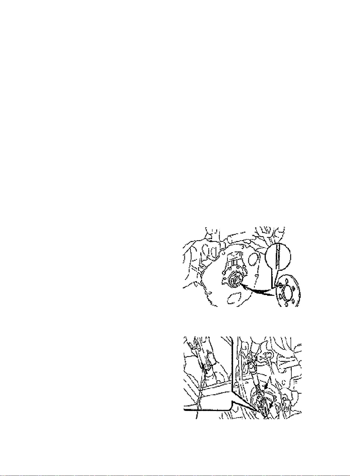
4.Fix the front end of crankshaft. Detach flywheel.
See (Figure 78)
5. Remove rear crankshaft end cover
6. Remove engine rear oil seal. See (Figure 75)
7. Install engine rear oil seal. See (Figure 76)
8. Install flywheel sub-assembly. See (Figure 79)
(a) Fix crankshaft.
(b) Install flywheel to crankshaft. as the sequence shown in the figure,
(c) Install and uniformly tighten and install bolt
T orque: 78N. m
9. Install clutch plate assembly
10. Install clutch case assembly
11. Install manual transaxle assembly
Figure 78
Figure 79
34
Page 42

Chapter 3 Lubrication System
(MR479Q, MR479QA, MR481QA)
Section 1 Oil Pressure Gage Sensor Replacement
1. Check oil level
Warm up the engine. Check the dipstick to ensure oil level between "L" and "F" after engine stopped
5 minutes. Check for leakage if it is too low. Fill oil to "F.
2. Check oil for deterioration. Water entry, discolor and dilution. Replace oil if it is obviously
deteriorated.
3. Detach oil pressure sensor assembly. See (Figure 80)
4. Install oil pressure gage sensor. See (Figure 81) Start engine to
normal operation temperature.
5. Check for oil pressure
6. Smear adhesive on 2 or 3 threads of the oil pressure sensor.
Install oil pressure sensor. See (Figure 82)
Figure 80
Figure 82
Figure 81
35
Page 43

Section 2 Oil Pump Assembly Replacement
1. Remove timing belt
2. Remove timing belt idler sub-assembly
3. Detach crankshaft timing pulley. See (Figure 74)
4. Remove the dipstick guide
5. Detach oil sump sub-assembly. See (Figure 83)
6. Detach oil strainer sub-assembly. See (Figure 84)
7. Detach oil pump assembly. See (Figure 85)
8. Remove oil pump oil seal
9. Install oil pump oil seal
10. Install oil pump assembly
11. Install oil strainer sub-assembly
12. Install oil sump assembly. See (Figure 86)
Figure 84
Figure 83
36
Figure 86
Figure 85
Page 44

13. Install the dipstick guide. See (Figure 87)
14. Install crankshaft timing pulley. See (Figure 77)
15. Install timing belt idler sub-assembly No.1
16. Install timing belt
17. Fill in engine oil
18. Check oil for leakage
Figure 87
37
Page 45

Section 3 Oil Filter Replacement
1. Detach oil filter sub-assembly. See (Figure 88)
2. Install oil filter sub-assembly. See (Figure 89)
Figure 88 Figure 89
3. Install drain plug
Clean and use new washer to install drain plug.
Torque: 54N. m
4. Oil fill
Capacity:
Oil refill amount with the filter replaced: 3.0L
Oil refill amount without the filter dry fill replaced: 2.80L
Dry fill: 3.3L
5. Check oil for leakage
38
Page 46

Section 4 Starter Replacement
1. Detach starter assembly. See (Figure 90)
2. Install starter assembly
Torque:
Bolt 37N. m
Figure 90
39
Page 47

Section 5 Generator Replacement
1. Detach V-belt of generator
2. Detach generator assembly
(a) Disconnect wire joint of generator.
(b) Remove wire of generator.
(c) Disconnect oil pressure switch interface.
(d) Disconnect A/C compressor switch connector.
(e) Open wire clips.
(f) Detach 2 bolts and generator.
3. Install generator assembly
Torque:
M12 bolt 18N. m
M14 bolt 58N. m
4. Transmit belt tilt and tension state inspection
40
Page 48

Chapter 4 Fuel System
(MR7131A, MR7151A, MR7161A)
Section 1 Check Fuel System Pressure
1. Remove the fuel tank from the vehicle
2. Check the fuel pump running
(a) Connect the positive and negative battery terminal to the concerned
fuel pump connector. See (Figure 91).
Notice: Do not start engine
The sound of fuel flowing can be heard if there is pressure.
Check fusible link, fuse, EFI open circuit relay, fuel pump, ECU and
wire connector if there is no pressure.
(b) Turn the ignition switch to "OFF" position.
3. Check fuel pressure
(a) Check battery electrical pressure to be above 12V.
(b) Detach negative terminal cable from the battery.
(c) Install pressure gage from the fuel delivery pipe. See (Figure 92).
(d) Connect battery negative terminal.
(e) Measure fuel pressure
Fuel pressure:
304-343kPa
Check fuel pipe & union, fuel pump, fuel filter if the pressure is too
low.
(f) Start engine. Measure fuel pressure at idle. Fuel pressure: 304-343kPa
(g) Check fuel pressure and retain the pressure for approximately 5min after the engine stopped.
Fuel pressure: 147kPa
Figure 91
Figure 92
41
Page 49

Section 2 Fuel Pump Inspection
1. Fuel pump
at 20°. Replace fuel pump if the resistance is not as specified.
(a) Check fuel pump resistance, 0.2~3.0
See (Figure 93)
(b) Fuel pump running:
Check fuel pump by connecting with battery. Replace fuel pump or wire if the running is not as specified.
See (Figure 94).
The test should be conducted within 10s to prevent coil from damage.
2. Fuel injector assembly
3
Injection V olume: 40~50cm
/s
Error between each injector: less than 10 cm
Replace injector if the injection volume is not as specified.
(a) Check for leakage: Disconnect the cable from the battery. The fuel drop/min is no more than 1 drop.
Ohmmeter
Ω
3
42
Battery
Figure 93 Figure 94
Page 50

Section 3 Fuel Injector Replacement
1. Check fuel for ejection.
2. Remove PCV ventilation hoses. See (Figure 95). Remove fuel pipe clamp.
3. Detach fuel hose sub-assembly
4. Detach fuel delivery pipe sub-assembly. See (Figure 96)
(a) Press the connector to lock the spring and pull the connector from the injector.
(b) Remove 2 screws and detach fuel delivery pipe with injector.
5. Remove fuel injector assembly
6. Install injector assembly
(a) Smear a light layer of oil on two O-rings and install them to injector. See (Figure 97).
(b) Install 4 injectors to feul delivery pipe by rotating them left and right. See (Figure 98).
(c) Install retain frame to each injector.
New O-ring
Figure 95 Figure 96
Upward
Rotate
Ratain Frame
Push
Figure 97 Figure 98
43
Page 51

7. Install fuel delivery pipe sub-assembly
(a) Install two washers in intake manifold. See (Figure 99).
(b) Install 4 injectors and fuel delivery pipe assembly into intake manifold .
(c) Temperarily install 2 bolts to attach the fuel delivery pipe to intake
manifold .
(d) Check injector for smooth rotation. See (Figure 100).
Hint: If injector doesn't rotate smoothly, replace O-ring with the injector
connector upward.
(e) Tighten the 2 bolts and attach the fuel delivery pipe to intake manifold
See (Figure 101).
Torque: 15N. m
Upward
Rotate
Washer
Figure 99
Figure 100 Figure 101
44
Page 52

Section 4 Fuel Pump Replacement
Figure 102
45
Page 53

1. Avoid fuel ejection
2. Disconnect fuel tank hose
3. Disconnect fuel tank return hose
4. Disconnect fuel tank gas exhaust hose
5. Detach fuel pump assembly with filter screen. See (Figure 103)
Using special tool, loose fuel tank cap. Be careful not to bend the fuel
level sensor arm when pulling out fuel pump.
6. Install fuel pump assembly. See (Figure 104). Replace ring seal .
Align the tab on the fuel pump to the notch on the fuel tank port. Tighten
the fuel tank cap with special tool.
Torque: 40N. m
7. Install fuel gas exhaust hose
(a) Install return hose;
(b) Install fuel hose;
(c) Check fuel for leakage.
Figure 104
Figure 103
New Washer
46
Page 54

Section 5 Fuel Emission Control System
1. Check the operation when the fuel is cut off.
(a) Warm up the engine for at least 2500rpm. Using sound grade meter , check injector's noise when running.
See (Figure 105).
(b) The noise from the injector should stop immediately after loosing the throttle. Repeat for several times.
2. Check fuel vapor emission control system. See (Figure 106)
(a) Disconnect vacuum pipe after starting the engine.
(b) Select "ACTIVE TEST" and "PURGE VSV (Vacuum Solenoid Valve)" from the display on the fault
diagnosis tester. Confirm vacuum at VSV port.
(c) Connect the vacuum pipe after completing "ACTIVE TEST".
(d) After conducting "ECM DATA MONITOR"on the fault diagnosis tester, select "PURGE VSV" to
check operation.
(e) Start the vehicle after warming up the engine to confirm the VSV status is changed from disconnected to
connected. See (Figure 107).
3. Check the fill fuel port cap and gasket for distortion or damage. See (Figure 108)
Sound Grade Meter
Figure 105 Figure 106
Figure 107 Figure 108
Gasket
47
Page 55

Section 6 Carbon Canister Replacement
1. Check and replace carbon canister
(a) Eye-inspect the carbon canister for crack or damage. See (Figure 109).
(b) Check the carbon canister's operation.
1. Plug the exhaust hole. See (Figure 110).
2
2. Blow air in through (4.71kpa, 48kgf/cm
hole is closed. Check and ensure air is blew out from the blow purge hole.
) fuel tank hole when the exhaust
Replace the carbon carnister if the operation is not as specified.
Figure 109
3. Blow air in through the fuel tank hole. Check and ensure air flows out from
the other hole without resistance.
Replace the carbon carnister if the operation is not as specified.
(c) Clean the carbon carnister: Plug the blowing tube, bleed air in through (4.71kpa,) fuel tank hole and goes
out from the exhaust port. See (Figure 111).
Figure 110 Figure 111
2. Vacuum Solenoid Valve (VSV)
(a) Using ohmmeter, check VSV open circuit. The resistance is 27-33 ¸ when the temperature is 20°. See
Ω
(Figure 112).
Ohmmeter
Trigger
Ohmmeter
No trgger
Figure 112 Figure 11 3
(b) Using ohmmeter, check VSV grounding. Replace VSV if it is continuity. See (Figure 113).
48
Page 56

(3) Check VSV operation from hole E to F and that the air flow should be difficult. See (Figure 114).
3. PCV sub-assembly
It should be easy for air to pass through the cylinder head.
Notice:
z Do not suck air through valve.
z Never put any object into the valve. Replace PCV if the operation is
not as specified.
z Blow air in from the intake manifold side. Check that the air flow
should be difficult. Replace PCV if the operation is not as specified. See
(Figure 115).
Near cylinder head
Cleaning pipe
Figure 115
Near the intake manifold
Air
Figure 114
49
Page 57

Chapter 5 Exhaust System
(MR7131A, MR7151A, MR7161A)
Component1
50
Figure 116
Page 58

1. Detach tail exhaust pipe assembly
Remove 2 bolts and the tail exhaust pipe assembly.
2. Remove intermediate exhaust pipe assembly
Replace exhaust system
Detach 2 bolts and intermediate exhaust pipe assembly.
3. Detach front exhaust pipe assembly
Remove 2 bolts and front exhaust pipe assembly.
4. Install front exhaust pipe assembly
Using vernier calipers, measure the free length of the spring.
Free length: 42mm
Using the new gasket, install the front exhaust pipe to the exhaust manifold.
Notice:
z Do not use removed gasket any more.
5. Install front exhaust pipe assembly.
Torque: 43N. m
6. Install intermediate exhaust pipe assembly
Using the new gasket, install the intermediate exhaust pipe to the front exhaust pipe.
Torque: 44N. m
7. Install tail exhaust pipe assembly
Using the new gasket, install the tail exhaust pipe to the intermediate
exhaust pipe. See
T orque: 43N. m
(Figure 117).
Tail Pipe side
8. Check exhaust for leakage
Washer
Figure 117
51
Page 59

Chapter 6 Cooling System Inspection
(MR7131A, MR7151A, MR7161A)
Section 1 System Check
1. Check the cooling system for leakage. See (Figure 118)
(a) Fill coolant into radiator. Install the tester onto the radiator cap port.
(b) Start engine.
(c) The water pump pressure is 118Kpa. Check the pressure and ensure the
pressure will not drop. If the pressure drops, check the port, radiator and
water pump for leakage. If there is no leakage, check the heat exchanger,
cylinder block and cylinder head.
2. Check the engine coolant level in the reservoir.
The coolant level should be between low and full marks.
3. Check coolant quality
Radiator Cap Tester
Figure 118
(a) Remove radiator cap.
To avoid being scalded, do not remove radiator cap while the engine and
radiator are still hot, as fluid and steam can be sprayed under pressure.
(b) There should not be excessive deposits of rust or scale around the radiator,
and the coolant should be free from oil.
(c) Reinstall the radiator cap.
4. Thermostat
Hint:
The thermostat temp indicates the valve opening temperature.
See (Figure 119).
(a) Immerse the thermostat in water and gradually heat the water.
(b) Check the valve opening temperature. Valve opening temperature: 80 -- 84°C
(c) Check the valve lift. See (Figure 120, Figure 121). V alve lift: 8mm or mor at
95°C
(d) Check the thermostat is fully closed when the thermostat is at low temperature
( 77°C).
≤
5. Radiator cap valve
Figure 119
Figure 120
8.0mm or
More
Standard opening pressure: 93-123kpa
Minimum opening pressure: 78kpa
If the opening pressure is less thanminimum, replace the radiator cap.
52
Figure 121
Page 60

6. Fan
(1) Check the cooling fan operation with low temperature (Lower than
83°C)
(a) Turn the ignition switch to “ON” position.
(b) Check that the cooling fan stops.
(c) Pull out the water temperature sensor connector. See (Figure
122)
(d) Connect the water temperature sensor to car body with the
wire and ground the wire.
(e) Check the cooling fan operation.
(f) Insert water temperature sensor connector.
(2) Check the cooling fan operation with high temperature (over 93°C)
See (Figure 123)
(a) Start engine and make the coolant temp. higher than 93°C.
Disconnest
Figure 122
> 93°C
(b) Check that the cooling fan turns.
Replace it with water temperature switch if it doesn't run)
(3) Check the cooling fan. See (Figure 124)
(a) Disconnect the cooling fan connector.
(b) Connect the battery and ammeter to the connector.
(c) Check that the cooling fan rotates smoothly and check
the reading on the ammeter.
Standard amperage: 5.7 - 7.7A
(d) Reconnect the cooling fan connector.
Figure 123
Amperometer
Battery
Figure 124
53
Page 61

Section 2 Water Pump, Thermostat and Radiator Replacement
Hoist the engine from the compartment. See "Provison 20, Section 2, Chapter 2".
1. Replace water pump. See (Figure 125)
(1) Drain the coolant.
(2) Detach timing belt.
(3) Detach power steering pump assembly.
(4) Remove the oil dipstick guide.
(5) Detach water pump assembly.
(6) Install water pump assembly.
(7) The installation is in the reverse order of the removal.
2. Replace thermostat
(1) Remove thermostat (See Figure 126).
(2) Install thermostat.
a. Install a new gasket to the thermostat. See (Figure 127).
Figure 125
b.Align the main valve of the thermostat to the top of the
stud. Insert the thermostat into the water inlet case.
Hint:
The main valve is set at around 10°C as shown in the figure. See (Figure 128).
(3) Install inlet connector.
Figure 127 Figure 128
3. Replace radiator
(1) Open radiator cap.
(2) Open the drain valve and drain the coolant.
Figure 126
(3) Detach radiator water inlet hose.
(4) Detach radiator water outlet hose.
54
Page 62

(5) Disconnect auto-transmission oil cooler input pipe (Auto-transmission).
(6) Disconnect auto-transmission oil cooler output pipe (Auto-transmission).
(7) Remove 4 bolts from the radiator mounting bracket. See (Figure 129).
(8) Detach radiator assembly, Remove 3 bolts. Detach the fan and fan shroud. See (Figure 130).
Figure 127 Figure 128
(9) Install the cooling fan assembly
(a) Fix the reservoir assembly on the cooling fan bracket with the bolt. Torque: 16 N. m.
(b) Install the fan and fan shroud with 3 bolts. Torque: 7.5N. m.
(c) Install the cooling fan assembly to radiator assembly with 3 bolts. Torque: 16N. m.
(d) Connect the overflow pipe on the reservoir assembly and radiator assembly. Fix it with the spring
band.
(f) The installation of the radiator assembly is in the reverse order of the removal.
55
Page 63

Chapter 7 Clutch
(MR7131A, MR7151A, MR7161A)
Component 1 (Hydraulic Manipulation)
56
Figure 131
Page 64

Section 1 Clutch Replacement
Hoist the engine from the compartment. See "Provison 20, Section 2, Chapter 2".
1. Remove manual transaxle assembly
2. Remove the clutch release fork. See (Figure 132)
3. Detach clutch release fork boot.
4. Detach clutch release bearing
5. Detach clutch release bearing fixed clamp
6. Remove clutch fork pivot pin
7. Align the clutch cover to the mark on the flywheel. Detach clutch cover. See (Figure 133)
8. Remove clutch plate
9. Check and remove clutch plate assembly. See (Figure 134)
10. Check clutch cover. See (Figure 135)
Depth wear: A: 0.6mm
Width wear: B: 5mm
Figure 132 Figure 133
Figure 134 Figure 135
57
Page 65

11. Using the dial gauge, check the flywheel runout. See
(Figure 136).
The maximum runout: 0.3mm
12. Check clutch release bearing
The bearing is permanently lubricated. There is no need to
lubricate or clean.
13. Check clutch plate
14. Install clutch cover. See (Figure 137)
Align the Clutch cover to the mark on the flywheel.
Hint:
(1) Uniformly tighten the bolt in the sequence shown.
Torque: 19 N. m
(2) Shake the clutch plate up and down, left and right to ensure
it is centered, then tighten the bolt.
15. Check and adjust the clutch cover. See (Figure 138)
Check the diaphragm tip flatness with the dial gauge with roller.
Max. roughness: 0.5mm.
16. Install the release fork pivot pin
17. Install clutch release fork boot
18. Install clutch release bearing fixed clamp
19. Install clutch release fork
20. Install clutch release bearing
21. Install manual transaxle assembly
Figure 136
Figure 137
58
Figure 138
Page 66

Chapter 8 Maunal Transaxle Assembly
(MR7131A, MR7151A, MR7161A)
Component 1
Figure 139
59
Page 67

Section 1 Manual Transaxle Replacement
1. Open the engine hood
2. Remove the battery
3. Remove clutch cylinder sub-assembly. See (Figure 140)
4. Detach transmission shift cable assembly. See (Figure 141)
5. Remove the connector and turn on the back-up lamp switch connector.
6. Disconnect vehicle speed sensor
Disconnect vehicle speed sensor connector.
7. Detach the front exhaust pipe
8. Drain transmission oil
9. Detach left & right front wheel hub nut
10. Detach left & right front wheel speed sensor (ABS)
11. Detach front balance rod
12. Detach left & right tie-rod with ball stud pin
13. Detach front balance rod
14. Detach left & right lower swing arm
15. Detach left & right front propeller assembly
16. Hoist the engine from compartment. See "Provision 20, Section 2, Chapter 2"
17. Detach starter assembly
18. Detach engine mounting bracket
19. Detach manual transaxle assembly
20. Install engine mounting bracket
21. Install manual transaxle assembly
22. Connect engine vibration insulating cushions
23. Install starter assembly
24. Install left & right front propeller assembly
25. Connect left & right lower swing arm
26. Connect left & right tie-rod with ball stud pin
27. Connect front balance rod
Figure 140
Figure 141
28. Connect left & right front speed sensor (ABS)
29. Installleft & right front shaft nut
30. Install front exhaust pipe
31. Connect speedometer sensor connector.
32. Connect back-up lamp switch connector.
33. Connect transmission shift cable assembly. See (Figure 141)
34. Install clutch sub-pump assembly. See (Figure 140)
60
Page 68

Section 2 Vehicle Speed Sensor Replacement
1. Disconnect vehicle speed sensor. See (Figure 142)
2. Remove bolt and vehicle speed sensor.
3. Install vehicle speed sensor. See (Figure 142)
4. Connect vehicle speed sensor connector. See (Figure 143)
Figure 142 Figure 143
61
Page 69

Section 3 Transmission Case Oil Seal
1. Remove transmission case oil seal. See (Figure 144)
2. Install transmission case oil seal. See (Figure 145)
Notice:
Be careful not to damage oil seal lip.
Figure 144 Figure 145
62
Page 70

Section 4 Transaxle Case Oil Seal Replacement
1. Using special tool, remove transaxle case oil seal. See (Figure 146)
2. Install transaxle case oil seal. See (Figure 147)
Figure 144 Figure 145
63
Page 71

Chapter 9 General Engine Troubles and Their
Troubleshooting
Section 1 Overview
The wide application of the electronic technologies to the vehicles brings innovation on diagnosis of the
vehicle, many varieties of diagnosis instruments that are very effective and efficient for the vehicle diagnosis
are innovated. Once the fault occurs, the best choice is to go to service station for help. However, even the
most advanced instrument has its limit. For some faults, manual diagnosis is far more convenient and easier
than that of instrument. In case of the crack, distortion and leakage of the components, the manual diagnosis
is even superior to the instrument diagnosis. The faults occurred shall be carefully analyzed and troubleshot
in accordance with the repair manual for normal usage.
Section 2 General Engine Fault and Troubleshooting
I. Fuel pipeline and circuit fault causing the engine starting failure
engine starting failure normally include: starter does not run or starter runs but fails to crank the engine, or
cranks the engine but cranks slowly; starter can crank but fail to start the engine. There are many causes that
result in starting failure, such as failures in starting system, ignition system, fuel injection system and engine
mechanical failure.
1. starter does not run or fails to crank the engine or cranks slowly
(1) Symptom: starter does not run or spongy rotation
(2) Causes:
b. Low battery voltage, excessive battery discharge, damaged generator or failure in charging circuit;
c. Battery terminal rust and backed out;
d. Failure in starting circuit, ECU can not receive STA signal;
e. Damaged starter.
2. engine can not start and crank
(1) Symptom
With the start switch on, starter can crank but fail to start the engine.
(2) Causes
a. Empty fuel tank;
b. Electrical fuel pump inoperative;
c. Injector inoperative;
d. Low fuel pressure;
e. Unreasonable starting operation;
f. Damaged throttle position sensor or no signal is sent to ECU due to the open in throttle position
sensor circuit;
64
Page 72

g. Ignition system failure;
h. Low engine compression pressure.
(3) Diagnosis and Troubleshooting
a. First, check the fuel tank for fuel level, turn on the ignition switch, if fuel gauge pointer does not
move or fuel level warning lamp lights, then the fuel tank is empty, fuel shall be filled at this time.
b. Check that the electrical fuel pump for operation. Remove the fuel tank, you may use a wire to
connect the two jacks of the fuel pump for short, then turn on the ignition switch. The fuel pump
operation sound shall be able to be heard from the fuel tank nozzle or fuel flow can be felt with hand
pinching the tube; or remove the return hose on the fuel pressure regulator, check that the fuel
flows out; Direct judgment can be made if it is equipped with fuel pressure gage.
If electrical fuel pump is inoperative, check whether the main fuse, main relay, fuel pump relay,
fuel pump control circuit and ECU are OK. If all of them are OK, check fuel pump circuit for open,
short or damaged check valve. Repair or replacement shall be made when problems are found.
c. If there is no injection sound in injector, check injector control circuit for fault. You may use a
testing lamp with big resistance to be connected to the injector wiring connector, turn on the ignition
switch. If the testing lamp lights up, it indicates that the injector has been damaged and shall be
replaced; if the testing lamp does not light up, check whether the main fuse, EFI relay, fuse, ignition
switch and ECU terminal are OK, repair or replace them if they are not OK.
d. If there is low fuel pressure, the injection amount would be small and the engine won't start, you
should check the fuel filter for block and fuel pump safety valve for damage and check whether the
fuel pressure regulator is within the normal range, otherwise those components shall be repaired or
replaced.
e. Electric injection engine normally spot contact start the engine.
f. Check for open in the throttle position sensor (TPS) circuit.
g. Check whether there is Diagnostic Trouble Code (DTC), if there is, check it by the DTC; if there
is not, check the high voltage spark for intensity, if it is too weak, check spark plug, high voltage
wire, high voltage coil, distributor cover for faults, if there are faults, repair or replace them.
h. Check the compression pressure in the cylinder, insert the compression pressure gauge into the
spark plug hole, completely open the throttle, measure the compression pressure while starting the
engine. If the compression pressure is less than 980kPa when engine speed is more than 250r/min,
remove and inspect the engine and troubleshoot it.
3. The engine cranks but can not start
(1) Symptom
When starting the engine, starter can crank the engine but fail to start the engine.
(2) Causes:
a. Ignition advance angle is unfavorable;
b. Ignition is out of sequence, there is misfire;
c. High voltage spark is too weak;
d. The fuel pressure is too low;
e. fuel pressure regulator leakage;
65
Page 73

f. The idle control valve is faulty;
g. The water temperature sensor is damaged;
h. The vacuum pressure sensor is damaged;
i. The air filter is blocked;
j. The injector leaks;
k. The compression pressure in the cylinder is too low;
l. The intake temperature sensor is damaged.
(3) Diagnosis and Troubleshooting
a. Check high pressure spark, check whether the high pressure spark on the ignition coil high pressure
bus and extension are OK, if the bus spark is week, replace the ignition coil, if the bus spark is OK
while the extension spark is too week, replace the ignition coil also; In addition, excessive spark
plug clearance will influence the starting feature, the clearance of the spark plug shall be adjusted
to normal value (0.8±0.1mm);
b. If there is low fuel pressure, check whether the battery voltage is OK, otherwise it shall be
troubleshot or replaced; check fuel pump check valve for leakage, check fuel filter and fuel pipe for
block, if there are leakage or block, replace or troubleshoot them;
c. If there is leakage for fuel pressure regulator, intake manifold is likely to be mixed with gasoline and
it is hard to start, troubleshoot or replace them;
d. Idle control valve can not be opened to maximum position due to mechanical wear, aging or control
circuit failure, the idle control valve shall be replaced and the control circuit failure shall be troubleshot;
e. If the water temperature sensor data is not accurate, it may cause small injection, check the water
temperature sensor based on the standard data and calibrate the data;
f. There is big time lag for intake pressure temperature sensor that makes it somewhat insensitive at
low speed and result in inaccurate injection, adjustment or replacement shall be made;
g. If the air cleaner filter is too dirty, the air flow resistance is excessively big, resulting in hard start,
as a result of it, the filter shall be replaced.
In a word, there are many factors causing the starting failure of the engine, analysis shall be made based on
the severe conditions of the faults. Generally speaking, check the ignition system first, then check intake
system, fuel system, control system, at last check the cylinder pressure, check the DTC before checking the
trouble. The diagnosis and troubleshooting procedures for starting failure of the engine are shown in (Figure
148).
66
Page 74

Engine can not start
Check the starting system Repair or replace the part if it is faulty
Check the high voltage spark
No high voltage spark or weak spark OK
Check the ignition system Is there any sign of cranking
No sign of cranking There is sign of cranking
Check the electric fuel pump for operation Check the air cleaner filter
Operative Inoperative OK Clogged
Check the injector Check the electric fuel Check the Replaced
pump and its control circuit spark clearance
Operative Inoperative
Measure the fuel pressure
Measure the fuel pressure Check the injector
Measure the vapor pressure,
water temperature and intake
Excessively low OK Check the control circuit air temperature sensor
Check the fuel Check thecylinder pressure Check the cylinder pressure
pressure regulator
Figure 148
II. Fuel pipeline and Circuit Fault for Hard Engine Starting
Hard engine starting indicates that starter can crank but fail to start the engine, or it may take multiple
consecutive starting efforts or long time rotation to successfully start the engine. For hard start fault, make
sure whether it occurs at cold or hot status or regardless of the cold or hot status.
1. Symptom
When starting, engine cranks at normal speed, but it takes longer to start or fails to start although cranks.
2. Causes:
a. Air cleaner is clogged;
b. Intake temperature sensor fault;
c. Water temperature sensor fault;
67
Page 75

d. Fuel pressure system abnormal;
e. Idle control valve fault;
f. Vacuum pressure sensor fault;
g. Ignition system fault;
h. The compression pressure in the cylinder is a little lower;
i. Injector leakage.
3. Diagnosis and Troubleshooting
a. Perform self-diagnosis first, check whether there is any DTC, if there is, find the reason and cause by the
DTC;
b.If it is hard for cold start but easy for hot start, check water temperature sensor and intake temperature
sensor for fault;
c. If the engine can not be started quickly in hot condition, the relief of the fuel pressure will be fast, then
repair and replacement shall be made;
d. If the spark is too weak, check high pressure coil, spark plug clearance and spark plug for carbon deposit,
repair or replace them one by one after isolating the problem;
e. Intake and exhaust valve is not completely closed, piston ring failure is likely to cause low compression
pressure in the cylinder, you should carefully repair intake & exhaust valve and seat, or replace them;
failed piston ring shall be replaced.
4. Diagnosis and Troubleshooting for hard starting and trouble shooting procedure. (Figure 149)
III. Fuel Pipeline and Circuit Faults for Poor Engine Operation
Poor engine operation includes: insufficient power, poor acceleration, poor deceleration, big fuel consumption,
rough idle and Engine overheat.
1. Insufficient Power
(1) Symptom:
Engine operation is normal without load but slow at load, insufficient power when uphill and not improved
even if the accelerator pedal is completely depressed, speed can not be increased and unable to reach the
maximum vehicle speed.
(2) Causes:
a. Air cleaner is clogged;
b. Poor intake system seal;
c. Intake pressure temperature sensor fault;
d. Low fuel pressure;
e. Broken pressure adjustor;
f. Clogged injector or poor atomization;
g. Throttle position sensor fault;
h. High pressure spark is too weak;
i. Improper valve clearance;
68
Page 76

j. Poor intake and exhaust valve seal, failed piston ring, low compression pressure;
h. Too many carbon deposit in spark plug and combustion chamber;
k. Water temperature switch and thermostat fault;
l. Aging of Oxygon sensor;
Engine is difficult to start
Check whether the air cleaner is clogged
Clogged
Troubleshooting
OK
NG
Check the idle control valve
Repair or replace
OK
Excessivly low
Check the fuel pressure
Service the electric fuel pump,
fuel filter and fuel pressure regulator
OK
Check the vacuum pressure sensor NG Replace
OK
Check the water temperature sensor and intake air temperature sensor
OK
Check the start switch signal
OK
Check the ignition timing
OK
Check the cylinder pressure NG Disassemble the engine
OK
Replace the ECU to retry
m. Incorrect ignition timing;
n. Check valve fault.
NG
Replace
No
Service the start signal wire
Misaligned
Adjust
Figure 149
69
Page 77

(3) Diagnosis procedure for insufficient engine power (Figure 150)
Insufficient power
Insufficient
Unable to be fully open
Check whether throttle valve can be fully open
OK
Clogged
Check whether the air cleaner is clogged
Clean or replace
OK
Abnormal
Check the throttle valve position sensor for failure
OK
NG
Check the water temperature switch and thermostat
Replace
OK
NG
Check the vacuum pressure sensor for failure
Replace
Adjust
Repair or replace
OK
Check the fuel pressure
fuel filter and fuel pressure regulator
OK
Check the oxygen sensor
OK
Check the injector
OK
Replace the spark plug, ignition coil and high voltage wire
OK
Disassemble the engine
2. Poor deceleration
(1) Symptom
Excessively low or high
Service the electric fuel pump,
Incorrect
Replace
Incorrect
Replace
Figure 150
Idling is normal, but the engine is frequently turned off upon sudden release of the accelerator pedal
during driving.
(2) Causes and Troubleshooting:
a. Throttle position sensor is damaged and shall be replaced;
b. Initial idling is not properly adjusted or automatic idle control is wrong, fuel cut RPM is too low,
ECU fault, repair or replace them.
70
Page 78

3. Poor acceleration
(1) Symptom
Engine speed can not be increased immediately after depressing the accelerator pedal, there is
time lag,and the acceleration reaction is delayed or there is slight fluctuation during the acceleration.
(2) Causes and Troubleshooting
a. There is fault in throttle position sensor, repair or replace it;
b. Poor intake system seal, repair it;
c. There is low fuel pressure, troubleshoot it;
d. Poor injector operation, clean or replace it;
e. Intake pressure temperature sensor fault, repair or replace it;
f. Check valve is damaged and shall be replaced;
g. Ignition advance angle is not correct and shall be adjusted;
h. Fuel pressure regulator is damaged and shall be replaced;
i. Air cleaner is clogged and shall be cleaned or replaced;
(3) Diagnosis procedure for poor acceleration (Figure 151)
Poor acceleration
Check the air tightness of the intake air system
Poor seal
Repair
OK
Clogged
Check whether the air cleaner is clogged
Clean or replace
OK
Abnormal
Check the throttle valve position sensor for failure
Repair or replace
OK
Abnormal
Check the fuel pressure
Service the electric fuel pump,
fuel filter and fuel pressure regulator
OK
Check whether the injector inject properly
at idle and maximum load
NG
Replace
OK
Yes
Check whether the check valve and EVAP are faulty
Repair or replace
OK
Check whether the vacuum pressure sensor is OK
OK
Adjust a ECU to retry
Figure 151
NG
Replace
71
Page 79

4. Big fuel consumption
(1) Symptom:
Engine power is ok, but the fuel consumption is big, exhaust pipe discharges black smoke.
(2) Causes and Troubleshooting:
a. When idling, idle speed is high and shall be adjusted;
b. Water temperature sensor fault, service or replace it;
c. Water temperature switch and thermostat fault, repair or replace it;
d. Oxygen sensor fault, repair or replace it;
e. Fuel pressure is big and shall be adjusted;
f. Injector fault (fuel leakage), repair or replace it;
g. Throttle position sensor fault, repair or replace it;
h. Fuel pressure regulator is damaged and shall be replaced;
i. Intake pressure temperature sensor fault, repair or replace it.
5. Unstable idle, liable to be turned off
(1) Symptom:
Engine starts normally, but the idle is unstable regardless of cold or hot status, idle speed is too low and
the engine is liable to be turned off.
(2) Causes and Troubleshooting
a. Poor idle control valve operation, repair or replace it;
b. Low idle speed and faulty or improperly adjusted idle control valve, troubleshoot it;
c. Water temperature sensor fault, repair or replace it;
d. Poor intake system seal, need to be repaired;
e. High voltage spark is too weak, spark plug carbon deposit or electrode clearance is too small, need
to be repaired, cleared and adjusted;
f. Pressure sensor fault, repair or replace it;
g. The compression pressure in the cylinder is too low, need to be serviced;
h. Fuel line pressure is too low, needed to be serviced;
i. Air cleaner is clogged, clean or replace it;
j. Poor injector atomization, fuel leakage, block or big injection variation, need to be repaired;
(3) Diagnosis procedure (Figure 152)
6. Unstable idle at cold status, liable to be turned off
(1) Symptom
During the cold start, idle is unstable and engine is liable to be turned off, the normal idle is recovered
after warming of the engine.
(2) Causes and Troubleshooting
a. Water temperature sensor fault, repair or replace it;
b. idle control valve fault, repair or replace it.
72
Page 80

7. Unstable idle or engine shut off at hot status
(1) Symptom
Idle speed is normal during the cold start and becomes unstable at hot status, idle speed is too
low or engine is shut off.
(2) Causes and Troubleshooting
a. Idle is adjusted too low, adjust it to normal condition;
b. Water temperature sensor fault, repair or replace it;
c. Poor injector operation or big injection variation, repair or replace it;
d. Poor water temperature switch and thermostat operation, repair or replace it;
e. Check valve is damaged and needs to be replaced.
Rough ildling, easy for engine shut off
Check whethe the air tightness of the intake system is good
Poor
Troubleshooting
OK
Inoperative
Check idle control valve for operation
Disassemble or replace
Operative
Reset the initial idle speed
Poor
Check the spark plug
Adjust the clearance or replace
OK
Check the fuel pressure
NG
pressure regulator and fuel filter
Check the electric pump, fuel
OK
NG
Check the injector
Replace
OK
NG
Check the pressure sensor
Replace
OK
Check the cylinder compression pressure NG Disassemble the engine
OK
Check and adjust the valve clearance
Figure 152
73
Page 81

8. Idle speed too high at hot status
(1) Symptom
The engine runs at fast idle during cold start and remains fast idle at hot status, leading to excessively fast
idle.
(2) Causes and Troubleshooting
a. The initial idle value is not properly adjusted,
b. High system fuel pipeline pressure, need to be adjusted;
c. Water temperature sensor fault, repair or replace it;
d. Water temperature switch and thermostat fault, repair or replace it;
e. Idle control valve fault, repair or replace it;
f. Throttle is binding and not tightly closed, repair or replace it;
g. Fuel evaporation control valve is always open, repair or replace it;
h. Speed sensor fault, repair or replace it.
9. Idle fluctuation
(1) Symptom
when idling, the engine speed fluctuates.
(2) Causes and Troubleshooting
a. Intake pressure temperature sensor fault, repair or replace it;
b. Check valve is damaged and needs to be replaced;
c. Water temperature sensor , water temperature switch and thermostat is poorly coordinated, repair,
adjust and troubleshoot them;
d. Oxygen sensor fault, need to be replaced;
e. Spark plug poor connection, repair or replace it;
f. Idle control valve and its control circuit fault, repair or replace it;
g. Idle switch is not closed, need to be repaired.
74
Page 82

10. Engine overheat (Table 6)
T able 6
Item Symptom Troubleshooting
Cause
Bad radiator cover
Repair or replace
Bad radiator hose Replace
Supplement welding, otherwise
Insufficient
coolant
Water
leaka ge
Bad radiator tube strap
replace it
Bad cylinder gasket Replace
Remedy with infiltration technology
Cracky cylinder block
or replace it
Poor water pump seal Replace the seal
Poor
cooling
Radiator is
faulty
Anti-freeze liquid not replaced
Bad thermostat
Water
leaka ge
Corrosion result in pin hole
Clogged cooling tube
Broken weld
Poor ventilation
Faulty water pump
Faulty fan voltage
Replace the anti-freeze liquid
Replace the thermostat
Supplement welding
Fill the pinhole with clear coat,
otherwise replace it
Repair and dredge
Improve the ventilation
Repair or replace the water pump
Troubleshooting, replace the motor if
it is damaged
Poor Fan
Disabled radiator temperature control
switch
Water jacket is clogged because of too much scale
Replace
Repair and dredge
Repair or replace the oil pan if there
Insufficient engine oil (oil leakage or d elaye d filling)
is oil leakage, refill the oil if it is not
supplemented in time
75
Page 83

11. General engine fault symptom and faulty area (Table 7)
r
y
m
y
Table 7
Suspect
Area
Control
system
Symptom
Intake abosolute pressure
sensor
Water temperature senso
Revolution speed sensor
Throttle valve position
sensor
Vehicle speed sensor
Difficult to start Poor idling Engine off
No fast ilde
Low idle speed
High idle speed
Difficult for hot start
Difficult for cold start
Unable to explode initially
Unable to explode completely
ccccccc cc
cccc cc c cc c
c
Idle hunting
Rough ildling
At urgent acceleration
When the accelerator pedal is releasec
ccc ccccc
Poor driving
During idling
Poor acceleration
Knock
Insufficient power
Hunting during driving
c
Fuel
system
Ignition
system
Intake
air
system
Fuel pump system
Fuel pressure regulator
Fuel filter and pipeline
Injector
Starter signal
Ignition coil
Spark plug
High pressure cable
Ignition timing
Igniter in the ECU
Throttle valve
Throttle valve bod
Air leakage in the intake
air syste
Air valve
cc c cc c
ccccc c cccc
cc c cccc
ccccc c ccc
cc
ccc
cccc c cc c
cc
cc c c c cc
c ccc
cccc c
cc c
cc ccccc c
ccccc
Power
supply
system
76
ECU power supply circuit
Ignition swtich
Main relay
Fuel pump rela
c
c
c
c
Page 84

IV. Exhaust Pipe Discharges Gas with Abnormal Color (or odor)
When there is failure in engine combustion system, the exhaust pipe discharges gas with abnormal color.
1. The discharged gas is thickly black
This is caused by incomplete combustion. Since the mixed air is too thick, the combustion is not complete and
part of the fuel is discharged without combustion, leading to decrease of engine power . At this moment, you
should check fuel pressure regulator, throttle position sensor, injector and ECU system and correct the
problems in time.
2. Exhaust is blue and stinks
This is caused by large amount of oil vapor mixed in the exhaust gas that enters in the cylinder and participates in combustion. One of the primary reasons is that the piston oil ring is dirty and damaged, and shall be
replaced; another reason may be the failure of valve oil seal or excessive clearance between the valve stem
and guide bush hole resulting in oil entering the combustion chamber for combustion, oil seal or valve guide
bush shall be replaced to resume normal condition.
3. Exhaust is white
This is caused by water or fuel vapor mixed in the exhaust. The primary reason is that cylinder head gasket
is damaged, resulting in slow infiltration of coolant into cylinder and the water vapor entry into the exhaust
pipe after combustion, cylinder head gasket shall be replaced to resume the normal condition.
Section 3 Engine Noise Diagnosis and Troubleshooting
Abnormal sounds generated during engine operation (e.g. knocking sound, chuckle, hiss, rattle) are called
noise.
Engine noise is primarily generated in valve train, connecting rod piston crankshaft components and other
accessory system. The following description discusses the diagnosis and troubleshooting of the noise generated in valve train and crankshaft connecting rod mechanism.
I. Diagnosis and troubleshooting of the noise in valve train
valve train consists of intake & exhaust camshaft , valve, valve bushing, tappetand counter gear.
1. camshaft noise
(1) camshaft end play is excessively big (normal intake camshaft : 0.030~0.085mm, exhaust camshaft : 0.
035~0.090mm) , when it exceeds 0.11mm and noise is generated, replace it;
(2) Camshaft bend is another cause for noise; it shall be aligned or scraped. ;
(3) Camshaft journal is excessively worn, resulting in big radial clearance between camshaft and bearing and
noise, replace it;
2. Valve group knock noise
(1) Valve noise is caused by excessive valve clearance, the valve spring seat flange is damaged and shall be
replaced;
(2) Valve spring knock noise is caused by broken valve spring. It shall be replaced;
77
Page 85

(3) Valve free movement noise is caused by dropped valve keeper or broken valve head. It shall be replaced;
(4) Noise between the intake & exhaust valve and valve bushing is caused by stagnation valve and bushing
that can not be closed, repair the bushing or replace it;
(5) V alve and valve seat can not be tightly closed and noise is generated, leading to abnormal engine operation.
Valve shall be grinded to fit, otherwise it shall be replaced.
3. Gear noise is mainly caused by excessive wear of the gear which results in excessive clearance,
generating the noise during the operation. The counter gear shall be replaced.
78
Page 86

II. Crankshaft connecting rod noise diagnosis and troubleshooting
No.N
N
g
play
d
n
d
b
g
1. crankshaft connecting rod noise cause and troubleshooting
Connecting rod
1
2
bearing noise
Ma in be a ring
3
oise area
noise
Crankshaft
axia l runout
noise
oise cause Troubleshootin
Excessive connecting rod bearing radial
Connecting rod cover bolt loosene
Replace the bearing
Tighte
Connecting rod bearing insert dimension
not a s specified result in rotation or
Replace the insert
rupture
Connecting rod bearing insert burne
Poor lubrication for connecting rod
earin
Drill the lubricant hole to normal,
Replace the insert
improve the lubricant line
Excessive main bearing raidal play Replace the main bearing
Main bearing cover bolt loosened Tighten
Main bearing insert burned Replace the insert
Poor lubrica tion for main bearing
Main bearing insert dimension not as
specified result in rotation or rupture
Smoothen the lubricant line or
enla rge the oil hole
Replace the main bearing insert
Excessive crankshaft bearing raidal play Adjust (pad) to normal
Excessive wear of the cranshaft thrust
washer
Replace the thrust washer
4
2. Piston ring leakage, knock and noise causes and troubleshooting
Flywheel
impact noise
Flywheel set bolt loosened Tighten
Noise cause Elimination method
Piston ring broken Replace
Excessive piston ring backlash Replace
Piston ring contra aperture Correct (stagger)
Piston ring is locked Replace
Insufficient elasticity of the piston ring Replace
Poor seal between te piston and cylinder wall Replace
79
Page 87

3. Piston knocking noise causes and troubleshooting
N
m
p
l
t
d
l
g
p
l
g
y
o. Ite
Ma in be a ring oil c hannel depth and width
Knock when
engine is cold
misaline d or insufficient oil pressure result
in poor lubrication of the cylinder wall
Excessively big clearance between the
Connecting rod journal is not parallel with
Connecting rod bushing axial declination Replace the bushin
Knock when
engine is hot
Excessively small clearance between the
Excessively small backlash and end gap for
Poor lubrication for cylinder wall and piston
Knock no
Piston pin and connecting rod end are
matter the
engine is cold
Connecting rod bearing is assembled too
or hot
Troubleshooting
Repair or adjust the oil pressure to
spe cif ica tion
Replace the piston to resume the normal
iston and the cylinder wal
Connecting rod ben
the ma in journa
Correct or replace the connecting ro
Replace the connecting rod
clearance
Pistion counter ellipse Replace the piston
istion and cylinder wal
the piston ring.
Repair the cylinder or replace the piston
Repair or replace the piston ring
Dredge the oil line to improve the
lubric ant spla shing problem
installed too tightly
tightly
Piston skirt ovality is too bi
Adjust piston pin tension to normal level
Adjust the bearing tension to normal level
Replace the piston with normal ovalit
80
Page 88

Chapter 10 Engine Management Unit
Section 1 System Description
Engine Control System generally consists of sensor, controller and actuator.
Sensor: convert the physical parameter of the device into electric signal (digital or analog) to monitor the
operating condition of the device and send these signals to the controller.
Controller: receive and process information sent from the sensor, and analyze the information to learn the
conditions of the device: use predefined control strategy and procedure, determine how to control the device
under current conditions; convert the decision into one or more orders and send them to the actuator. The
controller contains a microprocessor and stores pre-developed the programs or control software in the memory.
The controller can be regarded as the brain of the control system.
Actuator: receive orders from the controller, covert the electric signal into the action of the actuating elements (either action of electric element or mechanical movement). The actions of these elements will change
the operating conditions of the device and determine the operation and output of the device.
Large amount of information flows through the entire control system. Engine Control Unit learns the operation of the device from the information sent from the sensor, determines the approach and orders of the
control with the input and information stored by itself and ends up in sending the information about the orders
to the actuator.
I. Engine Fuel System Electronic Control System
Engine fuel system electronic control focuses on the quantified electronic control of the fuel, and actually is
the electronic control over the excessive air coefficient .
ECU controls the by controlling the fuel injection. When the engine is running, ECU receives the information about the air flow from the sensor and determines the fuel injection by calculations to make the excessive
air coefficient of the mixed air reach the predefined value. The control order output by ECU is only a control
signal to trigger the injector. ECU output the pulse width and timing in this signal.
The pulse width of injection signal determines the fuel amount of the injection. The pulse is the function of the
following parameter. The input and output are modified into closed loop control.
ECU calculate the target - air fuel ratio.
Air flow value.
Other operating conditions of the engine, such as throttle position sensor, exhaust manifold oxygen sensor.
low feature of the injector.
Engine ignition system electronic control
The control of Engine Control Unit over the ignition includes ignition advance angle control, knock control and
ignition power control (dewell angle control).
The control over the ignition advance angle is the basic function of the ignition control. Ignition advance angle
= ignition advance angle basic value + correction.
The control over the ignition advance angle also relates to the operating conditions of the engine. The factor
varying with the operating conditions can be reflected by the correction factor.
81
Page 89

Starting condition ¡ª fixed ignition advance angle
advance angle basic value - determined by MAP
Ignition advance angle control
Running condition
stable idle correction
air fuel ratio feedback correction
instantaneous correction
advance angle correction
engine overheat correction
knock control
maximum advance/delayed angle control
Special control
other correction
The control over the ignition advance angle is generally open loop control. But this open loop control is
different from the general open loop control, ECU test the knock signal with the knock sensor while controlling and outputting ignition advance angle orders in way of open loop. Once the knock occurs, it is converted
into closed loop control, and its feedback signal is knock sensor signal. Therefore, basically, it is also a closed
loop control.
Section 2 System Component and W orking Principle
ECU receives information from the sensors and sends control signals to actuators after processing and
analyzing these information. It plays a role of nerve center in the electronic control system.
ECU hardware consists of input level, micro-computer and output level (see figure 153).
Figure 153
82
Page 90

ECU microcomputer consists of microprocessor, memory, clock generator, timer, I/O interface and input
level A/D converter that are integrated in a large scale integrated circuit chip, that is SCM (Single Chip
Microcomputer).
1. Input level
The input signals from the sensor are pre-processed by the input level. The input signals are sent to protected
circuit first, sometimes through the signal converter and amplifier, and then sent to microcomputer.
The sensor signal is separated into switch type and analog type. Ignition on/off signal, camshaft position
signal, vehicle speed signal and A/C signal are switch type; Signals such as battery voltage, engine temperature,
intake temperature, airflow, intake manifold absolute pressure, throttle opening, excessive air coefficient,
knock, A/C refrigerant pressure are analog type. Analogy signal can only be processed by the digital microcomputer after being converted into digital signal by A/D converter. Hence, data collection shall be made
first for analog signal, and the sampling shall be maintained also.
Speed and crankshaft position reference signal from the sensor is processed in a dedicated circuit to restrain
the interference pulse.
2. Microcomputer
The microcomputer of the engine electronic control unit is integrated in a single chip microcomputer, consisting of the following:
(1) Microprocessor, microprocessor is also called as central processing unit (CPU), consisting of the following
three parts:
Arithmetic logic unit.
Register group.
Controller.
(2) System assembly, The data transferred among the internal sections of the single chip microcomputer
(SCM) is performed on the internal bus, while that between the SCM and other components is performed
on the external bus. The external bus is also called system bus. It is separated into data bus, address bus
and control bus.
(3) Memory, the memory is designed to store the binary data. The primary components of the memory are:
Memory.
Data register.
Address register, address decoder.
a. Memory controller
(4) A/D converter
(5) I/O interface.
(6) Clock generator.
(7) Timer
(8) CAPCOM unit.
(9) Watchdog timer.
(10) Interrupt system.
83
Page 91

3. Output Level
ECU output level is designed to send control signal to the actuators of the electronic control system based on
the orders of the microprocessor in the micro-controller. The microprocessor control the output level by
controlling the occurrence position of the pulse, its length and duty ratio.
(1) Injection output level
The microprocessor controls the pulse length of the injection output level by making sure whether to
trigger to circuit or not in the injection output level.
(2) Ignition input level
The ignition output level is designed to amplify the ignition signal from the microprocessor into the primary
current of the ignition coil.
(3) Electric fuel pump output level
ECU microcontroller control the pump relay through electric fuel pump output level, and then control the
on and off of the electric fuel pump based on the current operating conditions.
(4) Other output levels
Control the output levels of the idle control valve, carbon canister solenoid valve, malfunction indicator
lamp. MR479Q, MR479QA, MR481QA engine idle control are closed loop control system, their injection
and ignition control are also closed loop control system.
84
Page 92

Part II Chassis
Chapter 1 Transmission Control Device
Section 1 Transmission Control Device
Description on Transmission Control Device
This model is equipped with lever and cable transmission control devices, respectively used for 1.3L and 1.5L
engine, both of their gears are: 5 forward gears + 1 reverse gear.
PROBLEM SYMPTOMS T ABLE
Use the table below to help you find the cause of the problem. The numbers indicate the priority of the likely
cause of the problem. Check each part in order. If necessary, replace these parts.
Symptom
Transmission out of gear
Transmission shift difficult
Section 2 Lever Type T ransmission Control Device
Components
Suspected Area
1. Transmission control device selector (position
changing) cable (improperly assembled)
2. Cable or related parts worn
3. Cable assembly (incorrect)
4. Transmis sion (faulty)
1. Transmission control device selector (position
changing ) cable (improperly assembled)
2. Cable or related parts worn
3. Cable assembly (incorrect)
4. Transmission (faulty)
Control lever Assembly
Dust Proof Cover
Botton Panel
Assembly of body
Dust Proof Cover Retainer
Control Pull Rod Assembly
85
Page 93

Bottom Panel
Assembly of
Body
Control Pull Rod Assembly
Transmission Assembly
Replacement
1. Remove shift lever assembly
(1) Pull upwards to separate the shift lever assembly leather boot from the auxiliary console
(2) Loosen the shift lever set screw with inner hex wrench. Remove the shift lever assembly counterclockwise
2. Remove auxiliary console
3. Remove control lever dust cover
Remove the 4 nuts on the control lever dust cover and the body.
4. Remove dust cover retainer
5. Remove control pull rod assembly
(1) Remove the pull rod connecting bolt (Place 2)
(2) Remove 2 hex flange bolts (Place 1)
(3) Remove the 2 flange nuts attaching the control pull rod to the body in the trench
6. The installation is in the reverse order of the above operation.
Notice:
(1) Pull rod (to transmission) attach bolt torque: 40~50N.m
(2) The torque of the two nuts attaching the control mechanism to the body: 20~25N.m
86
Page 94

(3) Dust cover retainer shall be assembled well, otherwise the dust seal effect will be af-
fected
(4) Dust cover fixing nut torque: 20~25N.m
(5) Make sure the shift number words on the top of shift lever ball face towards the driving
direction of the vehicle, properly tighten the set screw of the shift lever
(6) Check whether the shift control is flexible and reliable; the shift lever shall be vertical
when in neutral shift.
Section 3 Cable T ype T ransmission Control Module
Components
Shift Lever Assembly
Shift Control Device
Cowl Baffle
Cushion
E Shaped
clip plate
Bottom Panel
Assembly of Body
Cotter Pin
Big Washer
Cotter Pin
Big Washer
E Shaped clip plate
Transmission
Assembly
87
Page 95

E Shaped
Clip Plate
Shift Control
Cables
E Shaped
Clip Plate
Ball Seat
Wave Washer
Replacement
1. Remove shift lever assembly
Bottom Bracket
Spindle II
Spindle I
Support
Plate
Shift Lever Assembly
Conjuction
Frame
Lever
Bush
Torsion Spring
Ball Pin Seat
Spring Bush
Bush
Ball Pin
(1) Pull upwards to separate shift lever assembly leather boot from the auxiliary console
(2) Loosen shift lever set screw with inner hex wrench. Remove the shift lever assembly counterclockwise.
2. Remove the auxiliary console
3. Remove the 4 nuts connecting manual shift assembly and the floor
4. Remove the shift cushion
5. Remove transmission control device assembly
(1) Remove the set nut on the cable seal press plate
(2) Remove the cotter pin and the flat washer connecting the cable and the rocker arm on the transmission
(3) Remove the E-shaped clip plate on the cable bracket retaining the cable
88
Page 96

6. Separate the manual shift assembly from the transmission control cable assembly
(1) Remove the E-shaped clip plate between the transmission control cable assembly and manual
shift assembly
(2) Remove the cotter pin and flat washer between the selector cable and shift assembly
(3) Remove the locking nut connecting the cable and the shift assembly
7. Installation is in the reverse order of the above operation
Notice:
(1) All the E-shaped clip plate and lock pins should be assembled correctly. Otherwise, the
shifting will be impacted.
(2) The shift device cushion should be correctly assembled. Otherwise, it will affect the seal
effect
(3) Torque of the 4 nuts attaching the shift assembly to the floor: 20~25N.m
(4) The set nut attaching the selector control cable to the shifter shall be adjusted properly
(if the set nut is improperly adjusted, the shift operation will be affected), when in neutral
shift, the shift lever shall be in correct position (you must check whether the shift control
is flexible and reliable in the meantime), after the adjustment is completed, tighten the
two nuts
(5) Make sure the shift number words on the top of shift lever ball face towards the driving
direction of the vehicle, properly tighten the set screw of the shift lever
89
Page 97

Components
Accelerator
Pedal Assembly
Chapter 2 Accelerator Pedal
Section 1 Accelerator Pedal
Hole Plug
Cowl Baffle
Accelerator Cable
Adjusting Nut
Connect
The Engine
Replacement
1. Remove the accelerator cable
Loosen the set nut attaching the accelerator cable to the accelerator
cable bracket on the engine, remove the accelerator cable from
the throttle valve rocker arm
2. Remove accelerator pedal
(1) Remove two set nut between the accelerator pedal
and vehicle body
(2) Separate the accelerator cable
3. Detach the accelerator cable
4.Install the accelerator cable and accelerator pedal assembly in the reverse order of the
above procedure.
Notice:
(1) Accelerator pedal assembly fixing bolt torque: 20~25N.m
(2) Properly adjust the position of the accelerator cable set screw to ensure the adequate
tension of the accelerator cable
(3) Check whether the accelerator control is flexible and reliable
90
Page 98

Chapter 3 Clutch Control System
Section 1 Clutch Control System
Clutch operating system description
This model is equipped with hydraulic and cable clutch control system, respectively used for 1.3L engine
1.5L engine.
Symptom Suspect ed Are a
1. C lutc h pedal position (Too low)
C lutch slips
C lutch does not releas e 1 . Hy dr au lic pipe line (Air in line)
Clutch noisy
2. C ont r ol mechanism ( St agnat ion)
3. C lutc h pedal fr ee stroke (too large)
1. Control system (Incorrect assembly & adjustment)
2. C lutc h assembly (Faulty)
PROBLEM SYMPTOMS T ABLE
Use the table below to help you find the cause of the problem. The numbers indicate the priority of the likely
cause of the problem. Check each part in order. If necessary, replace these parts.
Section 2 Clutch Cable Control Mechanism
Components
Connect The
Clutch Fork
Adjusting Nut
Clutch Cable
Assmbly
Cowl Baffle
Clutch and Brake
Pedal Assembly
91
Page 99

Clutch
Pedal
Bracket
Assembly
Adjusting Bolt
Brake Pedal Assembly
Connect The
Bushing
Clutch Cable
Clutch Pedal Assembly
Bushing
Sleeve
Clutch Pedal Torsion Spring
Retainer
Pedal Mat
Adjustment
1. Check and adjust clutch pedal height
The clutch pedal height should be 180~186 mm. Adjust the pedal by adjusting bolts.
2. Check and adjust clutch pedal stroke and free stroke
(1) The clutch pedal stroke: 134~142mm
(2) The clutch pedal free stroke: 10~30 mm
If the clutch pedal stroke and free stroke are not within specification, adjust it by adjusting the location of
the adjusting nut on the clutch cable. Re-adjust the clutch pedal height if necessary.
3. Check that the clutch pedal operates in flexible and reliable way
Notice:
(1) Make sure the clutch is fully applied and completely released when control the clutch
pedal.
(2) The clutch pedal must have certain free stroke. Otherwise, the full application of the
clutch may be impacted
(3) Tighten the lock nut after adjustment
Adjusting Nut
92
Page 100

Adjusting Bolt
Adjusting Bolt
Nut
Stroke
Minimum Distance from the Cowl Panel
Free
Stroke
Install Height
Replacement
1. Remove the clutch cable
(1) Loosen the clutch adjusting nut. Separate the clutch cable from the accelerator rocker arm
(2) Remove the 2 set bolts from the clutch cable on the cowl panel
(3) Separate the clutch cable from the clutch pedal
Adjusting Nut
2. Install the clutch cable assembly in the reverse order of the above procedure.
Notice:
(1) The clutch cable assembly on the cowl panel set bolt torque : 20~25N.m
(2) Check and adjust the pedal according to the above-mentioned requirement in
"Adjustment".
93
 Loading...