

Page 1

INSTALLATION
INSTRUCTIONS
Side by Side Refrigerators
With Design Guide
Monogram.com
Page 2
Safety Information
BEFORE YOU BEGIN
Read these instructions completely and carefully.
IMPORTANT – Save these instructions for
•
local inspector’s use. Observe all governing codes and
ordinances.
Note to Installer – Be sure to leave these
•
instructions with the Consumer.
• Note to Consumer – Keep these instructions with
your Owner’s Manual for future reference.
If you received a damaged unit, you should immediately
contact your dealer or builder.
Skill Level – Installation of this unit requires basic
mechanical, carpentry and plumbing skills. Proper
installation is the responsibility of the installer. Product
failure due to improper installation is not covered under
the Monogram Warranty. See the Owner’s Manual for
warranty information.
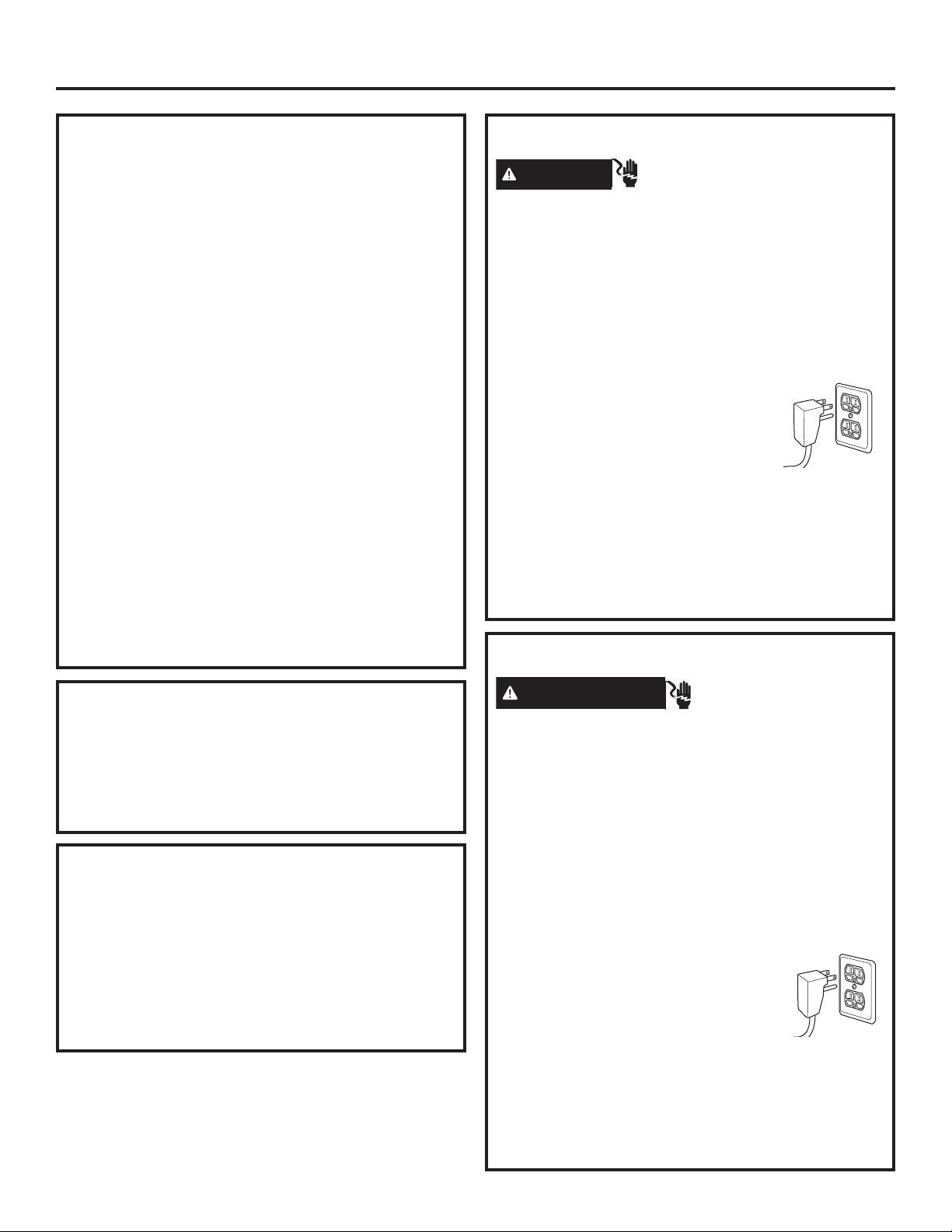
WARNING
Plug into a grounded 3-prong outlet.
Do not remove the ground prong.
Do not use an adapter.
Immediately discontinue use of a damaged supply cord.
If the supply cord is damaged it must be replaced by a
qualified service professional with an authorized service
part from the manufacturer.
WARNING
These appliances are top heavy, especially with any doors open, and must be secured to prevent tipping forward
which could result in death or serious injury. Read and follow the entire installation instructions for securing the
appliance with the anti-tip system.
WARNING
Keep flammable materials and vapors, such as gasoline, away from appliance. Failure to do so can result in fire,
explosion, or death.
WARNING
access to small parts during the installation of this product.
Electrical Shock Hazard.
Do not use an extension cord with this appliance.
Failure to follow these instructions can result in death,
fire, or electrical shock.
Follow the instructions in the section Grounding the unit.
This appliance must be installed with a means in the
fixed house wiring or circuit breaker for disconnecting the
appliance from the electrical supply after installation.
Tip Over Hazard.
Explosion Hazard.
To reduce the risk associated with choking, do not allow children under 3 years of age to have
CAUTION
This refrigerator is very heavy. To reduce the risk of person injury during maneuvering and installing this refrigerator, 3
people are required for proper installation of 36” wide model and 4 people are required for proper installation of a 42”
or 48” wide model.
CAUTION
and cabinet are necessarily small. Be careful closing doors when children are in the area.
For Monogram local service in your area, call 1.800.444.1845 or visit monogram.com.
For Monogram service in Canada, call 1.800.561.3344
For Monogram Parts and Accessories, call 1.800.444.1845 or visit monogram.com.
Lifting Hazard
Keep fingers out of the “pinch point” areas; clearances between the doors and between the doors
2
31-49171
Page 3
Consignes de Sécurité
AVANT DE COMMENCER
Veuillez lire toutes ces instructions attentivement.
• IMPORTANT – Conservez ces instructions à
l’usage de l’inspecteur local. Observez tous les codes et
décrets en vigueur.
Note à l’installateur – Assurez-vous de laisser ces
•
instructions au consommateur.
Note au consommateur - Conservez ces instructions
•
avec votre manuel d’utilisation pour
Si vous avez reçu un appareil endommagé, veuillez
communiquer immédiatement avec votre revendeur ou votre
entrepreneur.
consultation ultérieure.
Niveau de compétence – L’installation de cet appareil
exige des compétences de base en mécanique, menuiserie
et plomberie. La responsabilité d’une installation adéquate
relève de l’installateur. La garantie Monogram ne couvre
pas les défectuosités du produit causées par une installation
inadéquate. Consultez le manuel d’utilisation pour des
renseignements sur la garantie.
AVERTISSEMENT
Branchez l’appareil dans une prise à 3 broches mise à la terre.
N’enlevez pas la broche de mise à la terre.
N’utilisez pas un adaptateur.
Cessez immédiatement l’utilisation d’un cordon électrique
endommagé. Si le cordon électrique est endommagé, son
remplacement doit être exécuté par un technicien en réparation
qualifié au moyen d’un cordon de rechange autorisé par le
fabricant.
AVERTISSEMENT
Ces électroménagers sont lourds du haut, notamment lorsqu’une porte est ouverte, de sorte qu’ils doivent être fixés pour
prévenir un basculement vers l’avant susceptible d’occasionner des blessures graves ou la mort. Lisez et observez la totalité des
instructions d’installation pour connaître la façon de fixer l’électroménager sur le dispositif antibasculement.
AVERTISSEMENT
Gardez les matières et les vapeurs inflammables telles que l’essence à distance de l’électroménager. L’omission de prendre cette
précaution peut entraîner un incendie, une explosion ou la mort.
AVERTISSEMENT
à la portée des enfants âgés de moins de 3 ans.
Risque d’électrocution.
N’utilisez pas un cordon de rallonge avec cet électroménager.
Le non-respect de ces instructions peut occasionner un décès,
un incendie ou un choc électrique
Suivez les instructions de la section Mise à la terre de l’appareil.
Le circuit électrique auquel cet électroménager sera raccordé
doit comporter un disjoncteur ou un autre dispositif permettant
de couper l’alimentation électrique à l’appareil après l’installation.
Risque de basculement.
Risque d’explosion.
Pour réduire le risque d’étouffement pendant l’installation de ce produit, ne pas laisser les petites pièces
ATTENTION
Ce réfrigérateur est très lourd. Pour réduire le risque de blessure lors de la manutention de ce réfrigérateur, trois (3) personnes
sont nécessaires pour procéder à l’installation appropriée du modèle 36 pouces, quatre (4) pour l’installation des modèles 42 ou 48
pouces.
ATTENTION
l’armoire sont particulièrement restreints. Soyez prudent lorsque vous fermez les portes en présence d’enfants.
Risque lié à la manipulation d’un objet lourd
Gardez vos doigts éloignés des points de pincement. Les espaces entre les portes et ceux entre les portes et
Pour joindre le service Monogram de votre région, composez le 1.800.444.1845 ou visitez monogram.com.
Pour le service Monogram au Canada, composez le 1.800.561.3344.
Pour le service des Pièces et accessoires Monogram, composez le 1.800.444.1845 ou visitez monogram.com.
31-49171
3
Page 4

Contents
Safety 2, 3
Instructions for Standard Installation 5-22
Planning Guide
The Installation Space 6
Dimensions and Clearances 6
Customization Basics 7
Side Panels 7
Refrigerator Location 7
1/4” Framed Panel Dimensions 8
3/4” Overlay Panel Dimensions 9
130° Door Swing 10
90° Door Swing 11
Dispenser Trim 12
Installation Instructions
Tools, Hardware, Materials 13
Grounding the Unit 13
Step 1. Remove Packaging 14
Step 2. Move the Refrigerator into the House 14
Step 3. Install Water Line 14
Step 4. Installation with Filtration System 15
Step 5. Install Side Panels 15
Step 6. Anti-Tip Procedures 15
Step 7. Level Refrigerator 16
Step 8. Alternate Anti-Tip Procedure 16
Step 9. Adjust Door Swing 17
Step 10. Install Grille Panel 17
Step 11. Install 1/4” Framed Panels 18
Step 11A. Install Overlay Panels 19, 20
Step 12. Connect Water Supply 20, 21
Step 13. Connect Power, Close Grille Panel 21
Step 14. Start Icemaker 21
Step 15. Install Toekick 21
Inspect Final Installation 22
Instructions for Flush Installation 23-40
Planning Guide
The Installation Space 24
Dimensions and Clearances 24
Customization Basics 25
Custom Handle Design Guide 25
Refrigerator Location 25
Side Panels 25
1/2” Overlay Panel Dimensions 26
3/4” Raised Panel Dimensions 27
3/4” Raised Door Panel Routing 28
3/4” Raised Grille Panel Routing 29
Dispenser Trim 30
Side Cleats 30
Installation Instructions
Tools, Hardware, Materials 31
Grounding the Unit 29
Step 1. Remove Packaging 32
Step 2. Move the Refrigerator into the House 32
Step 3. Install Water Line 32
Step 4. Installation with Water Filtration System 33
Step 5. Install Side Panels 33
Step 6. Install Case Trim 33
Step 7. Anti-Tip Procedure 33-34
Step 8. Level Refrigerator 34
Step 9. Adjust Door Swing 35
Step 10. Install Grille Panel 36
Step 11. Install 1/4” Framed Panels 37
Step 11A. Install Overlay Panels 38
Step 12. Connect Water Supply 39
Step 13. Connect Power, Close Grille Panel 39
Step 14. Start Icemaker 39
Step 15. Install Toekick 40
Inspect Final Installation 40
Instructions for Stainless Steel Installation 41-49
Planning Guide
The Installation Space 42
Dimensions and Clearances 42
Customization Basics 43
Side Panels 43
Refrigerator Location 43
130° Door Swing 44
90° Door Swing 45
Installation Instructions
Tools, Hardware, Materials 46
Grounding the Unit 46
Step 1. Remove Packaging 47
Step 2. Moving the Refrigerator into the House 47
Step 3. Install Water Line 47
Step 4. Installation with Water Filtration System 48
Step 5. Install Side Panels 48
Step 6. Anti-Tip Procedure 48
Step 7. Level Refrigerator 49
Step 8, Alternate Anti-Tip Procedure 49
Step 9. Adjust Door Swing 49
Step 10. Connect Water Supply 50
Step 11. Connect Power, Close Grille Panel 50
Step 12. Start Icemaker 50
Step 13. Install Toekick 51
Inspect Final Installation 51
4
31-49171
Page 5

Instructions for Standard Installation
31-49171
5
Page 6
Design Guide - Standard Installation
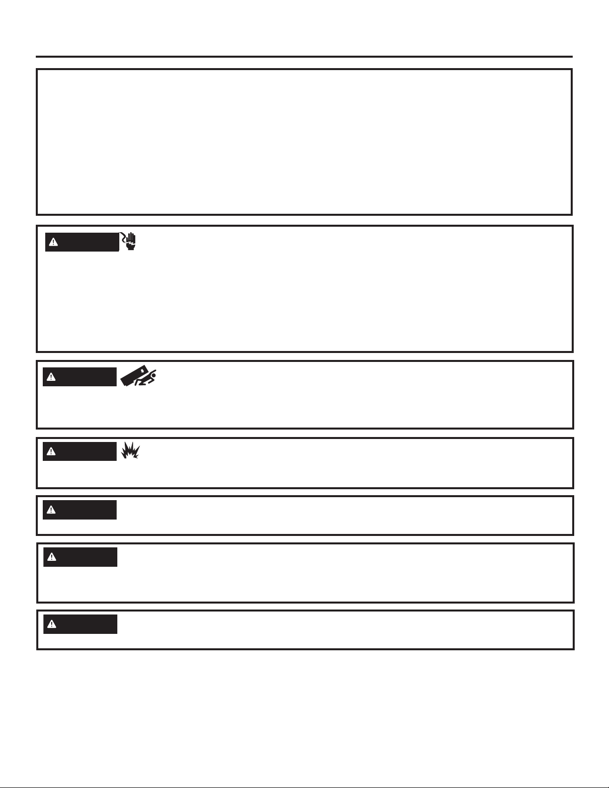
THE INSTALLATION SPACE
36" Models 12"
42" Models 18"
48" Models 20"
*Finished Width
6"
85" max
Finished
Opening
*The finished cutout width must be:
35-1/2” (90.17 cm) for 36” models
41-1/2” (105.41 cm) for 42” models
47-1/2” (120.65 cm) for 48” models
Water And Electrical Locations
The opening must be prepared with the electrical and
the cold water supply located as shown.
The Cutout Depth Must Be 24” (60.96 cm)
The refrigerator will project forward, slightly beyond
adjacent cabinetry for standard installation.
Additional Specifications
• A 115 volt 60Hz., 15 or 20 amp power supply is
required. An individual properly grounded branch
circuit or circuit breaker is recommended. Install
a properly grounded 3-prong electrical receptacle
recessed into the back wall. Electrical must be
located on the rear wall as shown.
• The water line can enter the opening through the
floor or back wall. The water line should be 1/4”
O.D. copper tubing or SmartConnect™ kit between
the cold water line and water connection location,
long enough to extend to the front of the refrigerator.
Installation of an easily accessible shut-off valve in
the water line is required.
Electrical
Area
24"
5"
Water Supply
3 1/2"
5"
75" From Floor
to Bottom
of Electrical
Area
5"
3 1/2"
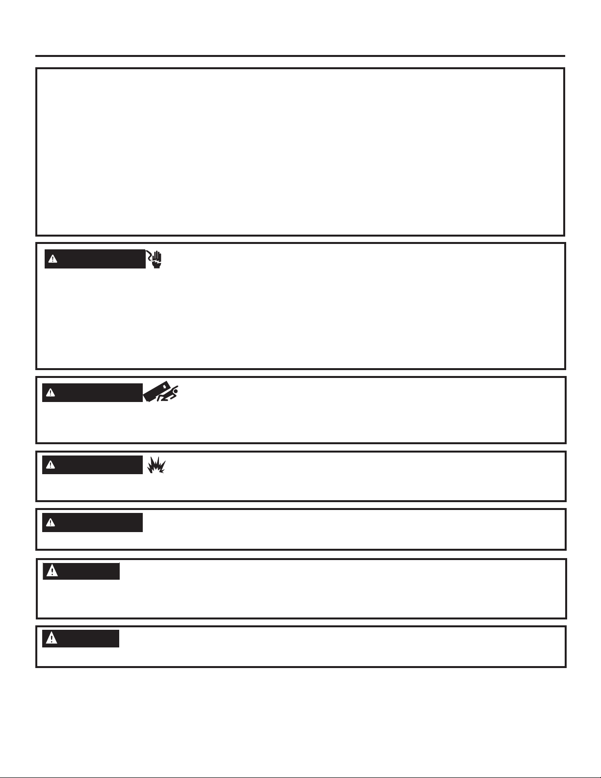
DIMENSIONS AND CLEARANCES
35", 41", or 47"
Case Width
*83-1/2"
at
Rear
36", 42" or 48"
Frame to Frame
Depth Including Handles 26-7/8”
Product Clearances
These refrigerators are
equipped with a 3-position
door stop. The factoryset 115° door swing can
be adjusted to 130°, or
to 90° on panel models
or 90° on stainless steel
models if clearance to
adjacent cabinets or walls
is restricted.
130° Door Swing
(Panel Models Only)
A
Models A B C
36” 13”
42” 13” (33.02 cm) 19” (48.26 cm) 26-5/8” (67.63 cm)
48” 15” (38.1 cm) 20” (50.8 cm) 28-5/8” (72.71 cm)
(33.02 cm) 15” (38.1 cm) 20-5/8” (52.39 cm)
Panel Models Only: Allow minimum clearances for
the freezer door (Dimension A) and fresh food door
(Dimension B) for a full 130° door swing and to allow for
pan removal.
For a 90° door swing, allow 4” (10.16 cm) min.
clearance to a wall. If the 90° door stop position is used,
pan access is maintained, but pan removal is restricted.
See the illustrations on pages 10 and 11 to determine
door swing interaction with adjacent cabinets or
countertops.
25-3/8" Framed Models
* Shipping height. The
*84"
From
Floor
115° Door Swing
A
90° Door Swing
B
refrigerator can be
adjusted to fit into a
cutout that is 84-1/2”
214.63 cm) in
height. Use leveling
legs and wheels
for a maximum 1”
(2.54 cm) height
adjustment.
B
23-7/8"
Behind
Frame
C
4”
*Min. Distance
to Wall
6
31-49171
Page 7
Design Guide - Standard Installation
CUSTOMIZATION BASICS:
These refrigerators are designed to be customized with decorative panels. Field installed custom door and grille
panels are required.
Optional Accessory Kits
ZKHSS2: Monogram Tubular Stainless Steel handles
designed to fit 3/4” (1.91 cm) overlay panels.
ZKHPSS1: Professional Tubular Stainless Steel
handles designed to fit 3/4” (1.91 cm) overlay panels.
Kit includes one handle. Order 2 kits for side-by-side
refrigerator models from your Monogram supplier
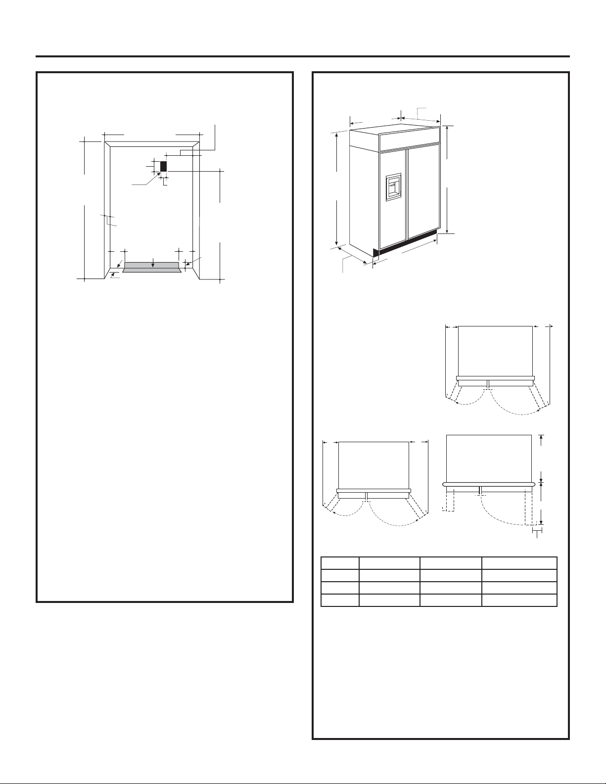
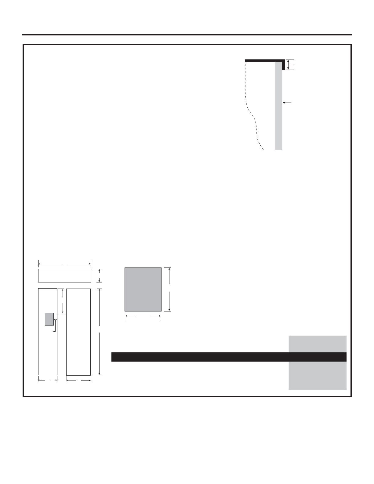
SIDE PANELS
Side panels must be used
whenever the sides of
the refrigerator will be
exposed. The 1/4”
(0.63 cm) side panels will
slip into the side case trim.
Secure the panels to the
refrigerator with stick-on
hook and loop fastener
strips. Order the side
panels from the cabinet
manufacturer.
• Cut a notch in the top
front corner as shown
to allow clearance for
corner keys in the front
side trim.
* Depending on installation height.
*84"
24"
*3" to 4"
2-9/16"
3/16"
1-7/8"
REFRIGERATOR LOCATION
• Do not install the refrigerator where the
temperature will go below 55°F (13°C). It
will not run often enough to maintain proper
temperatures.
• Do not install the refrigerator where temperatures
will go above 100°F (37°C). It will not perform
properly.
• Do not install the refrigerator in a location
exposed to water (rain, etc.) or direct sunlight.
• Install it on a floor strong enough to support it
fully loaded.
31-49171
7
Page 8
"
Design Guide - Standard Installation
1/4” (0.63 cm) FRAMED PANEL DIMENSIONS
5/16"
If you choose to install framed panels, they must be cut to the
dimensions shown. The panels will slide into the frame on the
Door
door and grille.
Non-Dispenser Models
If the custom panel is less than 1/4” (0.63 cm) thick and it fits
loosely in the door frame it can be backed up with a piece of filler
material or foam tape to improve the fit.
IMPORTANT NOTE: Maximum total panel weight:
• Fresh food door panel – 75 lbs.(34.0 kg)
• Freezer door panel – 53 lbs. (24.0 kg)
• Grille Panel – 18 lbs. (8.16 kg)
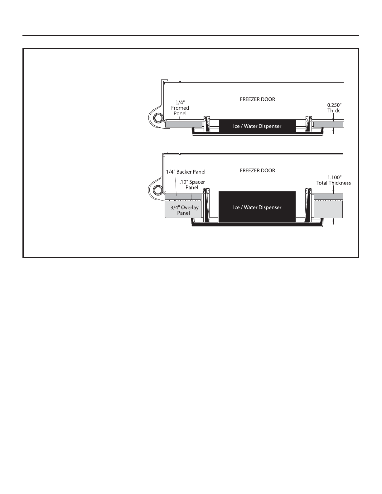
IMPORTANT NOTE – DISPENSER MODELS
The refrigerator is supplied with two dispenser trims, one for framed panels and one for overlay panels.
• If the panel is less than 0.250” (0.63 cm) thick, a noticeable gap may be created around the dispenser trim. Foam
tape may be applied on the door to improve the fit.
• If the panel is more than 0.250” (0.63 cm) thick, the dispenser trim cannot be secured to the door.
See Dispenser Trim Fit Example, page 12.
Trim
Reveal
1/4"
Panel
Grille Panel
Dispenser
Cutout
G
Freezer
Panel
D
A
B
F
C
Dispenser Cutout
The framed panel must be 1/4” (0.63 cm) nominal
thickness to fit the dispenser trim.
15-3/8
9-5/8"
Dispenser Cutout
Fresh
Food
Panel
Side-by-Side (in inches)
ABCD E F G
36” Models 33-7/8 9 68-3/8 14-9/16 18-9/16 17-13/16 3-1/8
Position
42” Models 39-7/8 9-1/2 68-3/8 14-9/16 24-9/16 17-13/16 3-1/8
E
48” Models 45-7/8 9-1/2 68-3/8 18-9/16 26-9/16 17-13/16 5-1/8
8
31-49171
Page 9
"
Design Guide - Standard Installation
3/4” (1.91 cm) OVERLAY PANEL
DIMENSIONS
For a more custom appearance, overlay panels may
be installed on trimmed models. The overlay panel
must be secured to a 1/4” (0.63 cm) thick backer
panel which slides into the trim. A spacer panel 0.10”
(0.25 cm) thick must be placed between the overlay
Door
3/4"
Overlay
Panel
Overlay Panel
Spacer Panel
Backer Panel
and backer panel.
Assemble the panels with glue and screws:
• Center the spacer panel on the backer panel, left to
right and top to bottom. Secure the panels with glue.
• Center the spacer and backer panel on the overlay
panel and secure with glue and screws. Screws
must be countersunk into the backer panel.
1/4"
Backer
Panel
.250” + .10” + .750” = 1.100” Total Panel Thickness
0.63 + 0.25 + 1.91 = 2.79 cm
.10"
Spacer
NOTE: Left-to-right offset
is not always equal to topto-bottom offset.
IMPORTANT NOTE – DISPENSER MODELS
The refrigerator is supplied with two dispenser trims, one for framed panels and one for overlay panels. The
overlay dispenser trim is designed to fit a total panel thickness of 1.100”.
• If the panel is less than 1.100” (2.79 cm) a noticeable gap may be created around the dispenser trim.
• If the panel is more than 1.100” (2.79 cm) the dispenser trim cannot be secured to the door.
See Dispenser Trim Fit Example, page 12.
• The overlay panel must be constructed according to the specifications shown to achieve the correct total
thickness.
• Alternative panel construction methods such as securing a 3/4” (1.91 cm) panel to a 1/4” (0.63 cm) backer
panel cannot be used. Another method, routing a 3/4” (1.91 cm) thick panel on all sides, cannot be used.
These methods will not result in the required 1.100” (2.79 cm) panel thickness.
Grille Panel
Dispenser
Cutout
G
Freezer
Panel
D
A
B
F
Dispenser Cutout
15-3/8
*Cut the dispenser opening after the backer, spacer and overlay
panels have been assembled.
IMPORTANT NOTE: Maximum total weight for the
assembled panels:
• Fresh food door panel – 75 lbs. (34.0 kg)
• Freezer door panel – 53 lbs. (24.0 kg)
• Grille Panel – 18 lbs. (8.16 kg)
9-5/8"
Dispenser Cutout
Position
Fresh
Food
Panel
E
C
36” Side-by-Side (in inches)
ABCD E F G
1/4” Backer Panel 33-7/8 9 68-3/8 14-9/16 18-9/16
.10” Spacer Panel 33 8-3/8 67 13-1/4 17-1/4
3/4” Overlay Panel 34-1/8 9-1/4 68-5/8 14-13/16 18-13/16 17-13/16 3-1/4
42” Side-by-Side (in inches)
ABCD E F G
1/4” Backer Panel 39-7/8 9-1/2 68-3/8 14-9/16 24-9/16
.10” Spacer Panel 39 8-5/8 67 13-1/4 23-1/4
3/4” Overlay Panel 40-1/8 9-3/4 68-5/8 14-13/16 24-13/16 17-15/16 3-1/4
48” Side-by-Side (in inches)
ABCD E F G
1/4” Backer Panel 45-7/8 9-1/2 68-3/8 18-9/16 26-9/16
.10” Spacer Panel 45 8-5/8 67 17-1/4 25-1/4
3/4” Overlay Panel 46-1/8 9-3/4 68-5/8 18-13/16 26-13/16 17-15/16 5-1/4
31-49171
9
Page 10
Refrigerator
Design Guide - Standard Installation
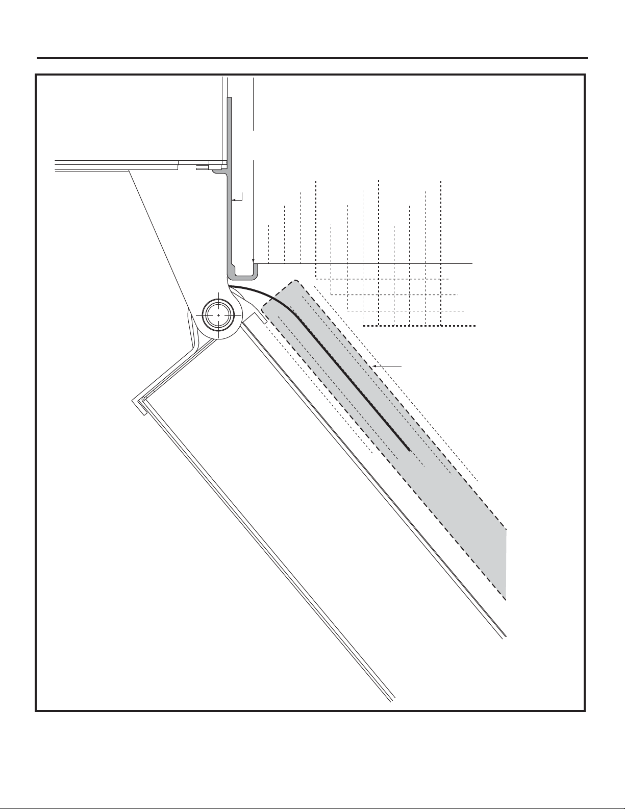
Frameless Cabinets: The case trim
overlaps cabinets at the top and sides.
Therefore, frameless cabinets may require
23-7/8" From
Rear of
Refrigerator
filler strips to prevent interfeence with
cabinet door swing. The opening must
allow for filler strips.
Top View
130° DOOR SWING
Scale 1:1
Case
Trim
Door
1/4"
1/2"
3/4"
1"
1-1/4"
2"
1-3/4"
1-1/2"
Stainless Steel
1/4"
2-1/2"
2-1/4"
3/4" Overlay
(Nominal Size)
1/2"
2-3/4"
Panel
3/4"
3"
1/4"
1/2"
3/4"
1"
1"
1-1/4"
IMPORTANT NOTE –
FOR DISPENSER MODELS:
Dispenser models are supplied with two
dispenser trims, one to fit framed panels
and one for overlay panels. Dispenser
trim fit to the custom panel depends on
correct panel thickness. Framed panels
must be 1/4” (0.63 cm) nominal. Overlay
panels should be constructed as shown
to accomplish a total 1.100” (2.79 cm)
thickness. See pages 19 and 20 for details.
10
31-49171
Page 11
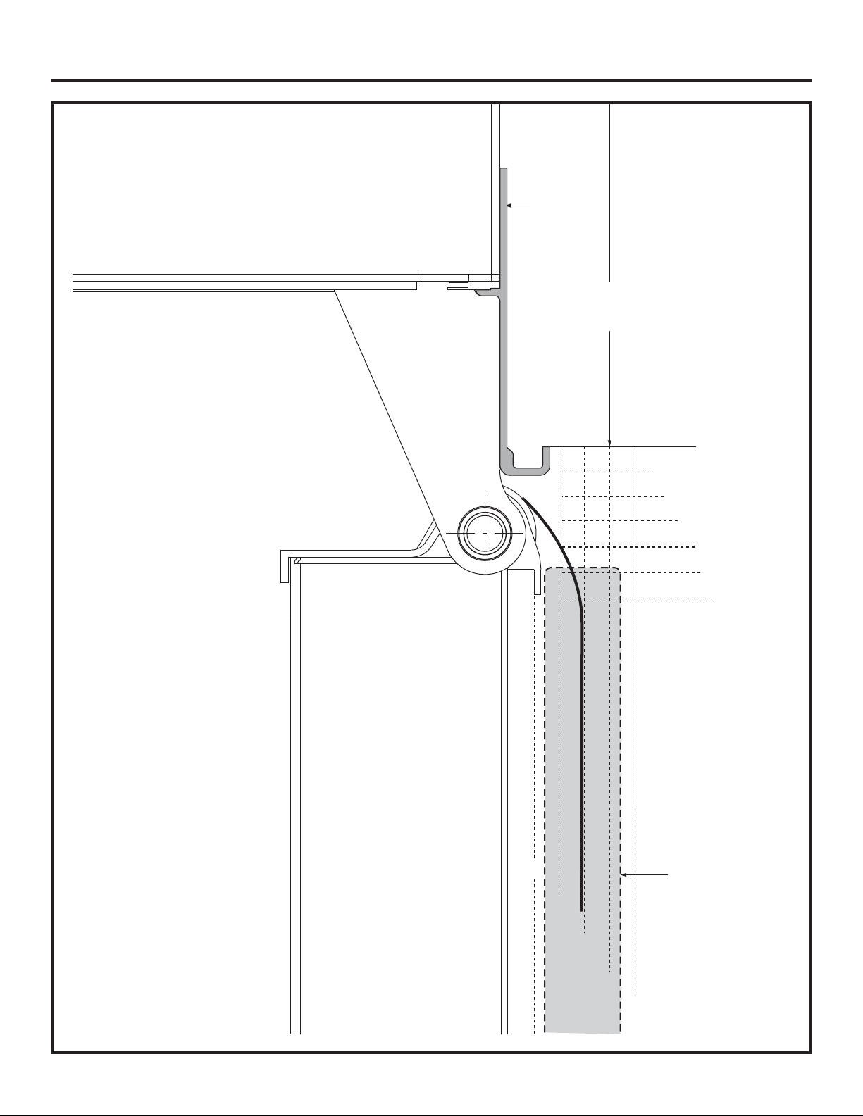
Design Guide - Standard Installation
Frameless Cabinets:
The case trim overlaps
cabinets at the top
Refrigerator
Case Trim
23-7/8"
From Rear of
Refrigerator
and sides. Therefore,
frameless cabinets may
require filler strips to
prevent interference with
cabinet door swing. The
opening must allow for
filler strips.
1/4"
Top View
90° DOOR SWING
Scale 1:1
IMPORTANT NOTE –
FOR DISPENSER MODELS:
Dispenser models are supplied
with two dispenser trims, one
to fit framed panels and one for
overlay panels. Dispenser trim
fit to the custom panel depends
on correct panel thickness.
Framed panels must be 1/4”
(0.63 cm) nominal. Overlay
panels should be constructed
as shown to accomplish a total
1.100” (2.79 cm) thickness
pages 19 and 20 for details.
. See
Door
1/4"
1/2"
3/4"
1"
1-1/4"
1-1/2"
Stainless Steel
3/4" Overlay
Panel
(Nominal Size)
1/2"
3/4"
31-49171
1"
1-1/4"
11
Page 12
Design Guide - Standard Installation
DISPENSER TRIM FIT EXAMPLES:
(NOT TO SCALE)
1/4” (0.63 cm) FRAMED
PANEL
• The dispenser trim fits over the
custom panel and snaps into the freezer
door.
• The clips will not engage the door if
the panel is more than 0.250”
(0.63 cm) thick.
• If the panel is less than 0.250”
(0.63 cm) thick, a noticeable gap may
be created around the dispenser trim.
3/4” (1.91 cm) OVERLAY
PANEL
• The dispenser trim fits over the
custom panel and snaps into the
freezer door.
• The clips will not engage the door if
the panel is more than 1.100” (2.79
cm) thick.
• If the panel is less than 1.100” (2.79
cm) thick, a noticeable gap may be
created around the dispenser trim.
1/4” Dispenser Trim
3/4” Overlay Dispenser Trim
12
31-49171
Page 13
Installation Instructions - Standard Installation
TOOLS AND MATERIALS REQUIRED
• Tinsnips to cut banding
• Stepladder
• 1” Bit extension
• Tape measure
• Gloves
• 1/4” Drywall screws
• 5-Gal. Bucket with cover
• 6” Spirit level
• Appliance hand truck
• Tubing cutter
• 7/16” open-end wrench
• #2 Phillips screwdriver
• Drill and appropriate bits
• 5/16”, 7/16” socket
• Safety glasses
• 1-1/8” open end wrench
• Pliers
• 1/4”, 5/16” Combo Rachet
• 35” long 2x4 for Anti-Tip support
• 1/4” copper water line tubing or SmartConnect™
Refrigerator Tubing kits
• Water shut-off valve
• Custom panels for doors and grille panel
• Screws to secure refrigerator to cabinetry
• Stick-on hook and loop fastener strips for 1/4” side
panels
GROUNDING THE REFRIGERATOR
WARNING
Failure to follow these instructions can result in death,
fire, or electrical shock.
The power cord of this appliance is equipped with a
3-prong (grounding) plug which mates with a standard
3-prong (grounding) wall receptacleto minimize the
possibility of electric shock hazard from this appliance.
Have the wall outlet and circuit checked by a qualified
electrician to make sure the outlet is properly grounded.
Where a standard 2-prong wall outlet
is encountered, it is your personal
responsibility and obligation to have
it replaced with a properly grounded
3-prong wall outlet.
DO NOT, UNDER ANY
CIRCUMSTANCES, CUT OR REMOVE THE THIRD
(GROUND) PRONG FROM THE POWER CORD.
DO NOT USE AN ADAPTER PLUG TO CONNECT
THE REFRIGERATOR TO A 2-PRONG OUTLET.
DO NOT USE AN EXTENSION CORD WITH THIS
APPLIANCE.
Electrical Shock Hazard.
HARDWARE SUPPLIED
• Water filter bypass plug
• Toekick
• 1/4” nut and ferrule
• Dispenser trim for overlay panels (for use with
Custom Panel models).
FLOORING
For proper installation, this refrigerator must be placed
on a level surface of hard material that is at the same
height as the rest of the flooring. This surface should
be strong enough to support a fully loaded refrigerator,
or approximately 1,500 lbs.(680.39 kg).
NOTE: Protect the finish of the flooring. Cut a large
section of the cardboard carton and place under
the refrigerator where you are working.
31-49171
MISE À LA TERRE DU RÉFRIGÉRATEUR
AVERTISSEMENT
électrique.
Le non-respect de ces instructions peut entraîner des
risques d’incendies, des chocs électriques ou la mort.
Le cordon d’alimentation de cet appareil est équipé
d’une fiche à trois broches (pour une mise à la terre)
qui s’adapte à la prise de courant standard à 3 broches
(pour une mise à la terre) pour minimiser les risques de
chocs électriques par cet appareil.
Faites vérifier la prise murale et le circuit électrique par
un électricien qualifié pour s’assurer que le système est
correctement mis à la terre.
Dans le cas d’une prise biphasée,
l’installateur a la responsabilité et
l’obligation de la remplacer par une prise
triphasée correctement mise à la terre.
NE COUPEZ PAS OU N’ENLEVEZ
PAS, SOUS AUCUN PRÉTEXTE, LA
TROISIÈME BROCHE DE MISE À LA TERRE DU
CORDON D’ALIMENTATION.
N’UTILISEZ PAS D’ADAPTATEUR POUR BRANCHER
LE RÉFRIGÉRATEUR À UNE PRISE BIPHASÉE.
N’UTILISEZ PAS DE RALLONGE AVEC CET
APPAREIL.
13
Risque de choc
Page 14
Installation Instructions - Standard Installation
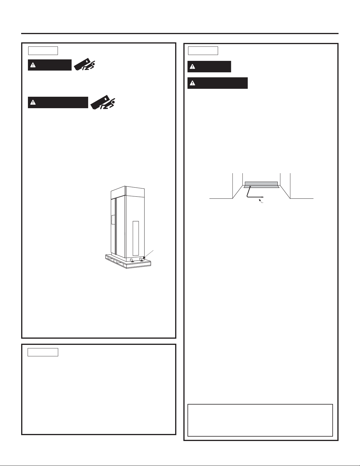
STEP 1 REMOVE PACKAGING
WARNING
The refrigerator is much heavier at the top than at the
bottom—be careful when moving. When using a hand
truck, handle from the side only.
AVERTISSEMENT
basculement Le réfrigérateur est beaucoup plus
lourd en haut qu’en bas. Il faut être prudent lors des
déplacements. Si un diable est utilisé, il faut soulever
le réfrigérateur sur le côté seulement.
• Carefully cut banding at the top and bottom, remove
the outer carton.
• Slide out the back corner posts (2).
• Slide the carton off the top of the cabinet.
NOTE: IT IS NOT NECESSARY TO LAY THE
CABINET DOWN IN ORDER TO REMOVE THE
SKID!
• The unit is secured to the
skid with 4 slotted tie-down
straps. Remove the six
7/16” bolts from the base
channels in the tie-downs.
• Remove the six 7/16” bolts
securing the straps to the
skid.
NOTE: DO NOT ATTEMPT
TO ROLL UNIT OFF SKID.
• The support blocks on the
bottom of the refrigeration
case must be removed before the refrigerator is
taken off the skid or damage will occur. Carefully
tilt the refrigerator and slide the blocks out from
beneath.
• Remove the toekick and set aside for final
installation.
• Lift the refrigerator off the skid with an appliance
dolly. Handle from the sides.
Tip Over Hazard.
Risque de
Remove
Toekick
Tie Downs
STEP 2 MOVE THE REFRIGERATOR
INTO THE HOUSE
• Re-use the corner posts from the packaging to
protect stainless steel models. Run the appliance
dolly straps over the posts and under the handles.
• Leave the protective film on the refrigerator until
installation is complete. IMPORTANT: Never lift the
refrigerator by the handle or push against the grille
panel; this could cause damage or misalignment.
• Avoid laying the unit on its back or side to prevent
sealed system restrictions.
STEP 3 INSTALL WATER LINE
WARNING
AVERTISSEMENT
alimentation d’eau potable seulement.
• A cold water supply is required for automatic
icemaker operation. The water pressure must be
between 40 and 120 p.s.i. (275-827 kPa).
• Route 1/4” OD copper or SmartConnect™ plastic
tubing between house cold water line and the water
connection location.
• The tubing should be long enough to extend to the
front of the refrigerator. Allow enough tubing to
accommodate the bend leading into the water line
connection.
NOTE: The only Monogram approved plastic tubing is
supplied in the SmartConnect™ Refrigerator Tubing kits.
Do not use any other plastic water supply line because
the line is under pressure at all times. Other types of
plastic may crack or rupture with age and cause water
damage to your home.
SmartConnect™ Refrigerator Tubing Kits are available
in the following lengths:
2’ (.6 m) WX08X10002
8’ (2.4 m) WX08X10006
15’ (4.6 m) WX08X10015
25’ (7.6 m) WX08X10025
Shut off the main water supply.
Turn on the nearest faucet long enough to clear the line
of water.
• Install a shut-off valve between the icemaker water
valve and cold water pipe in a basement or cabinet.
The shut-off valve should be located where it will be
easily accessible.
• Turn on the main water supply and flush debris.
Run about a quart of water through the tubing into a
bucket. Shut off the water supply at the shut-off valve.
NOTE: Saddle type shut-off valves are included in
many water supply kits. Before purchasing, make sure
a saddle type valve complies with your local plumbing
codes.
NOTE: Commonwealth of Massachusetts Plumbing
Codes 248CMR shall be adhered to. Saddle valves
are illegal and use is not permitted in Massachusetts.
Consult with your licensed plumber.
Connect to potable water supply
only.
Raccordez l’appareil à une
Floor
Cold Water Line
14
31-49171
Page 15
Installation Instructions - Standard Installation
STEP 4 INSTALLATION WITH
HOUSEHOLD WATER
FILTRATION SYSTEM
Skip this step if you do not have a household
water filtration system
If the water supply to the refrigerator is from any
household water filtration system, the filter cartridge
should be removed. For better ice and water
performance, remove the filter and install the filter
bypass plug.
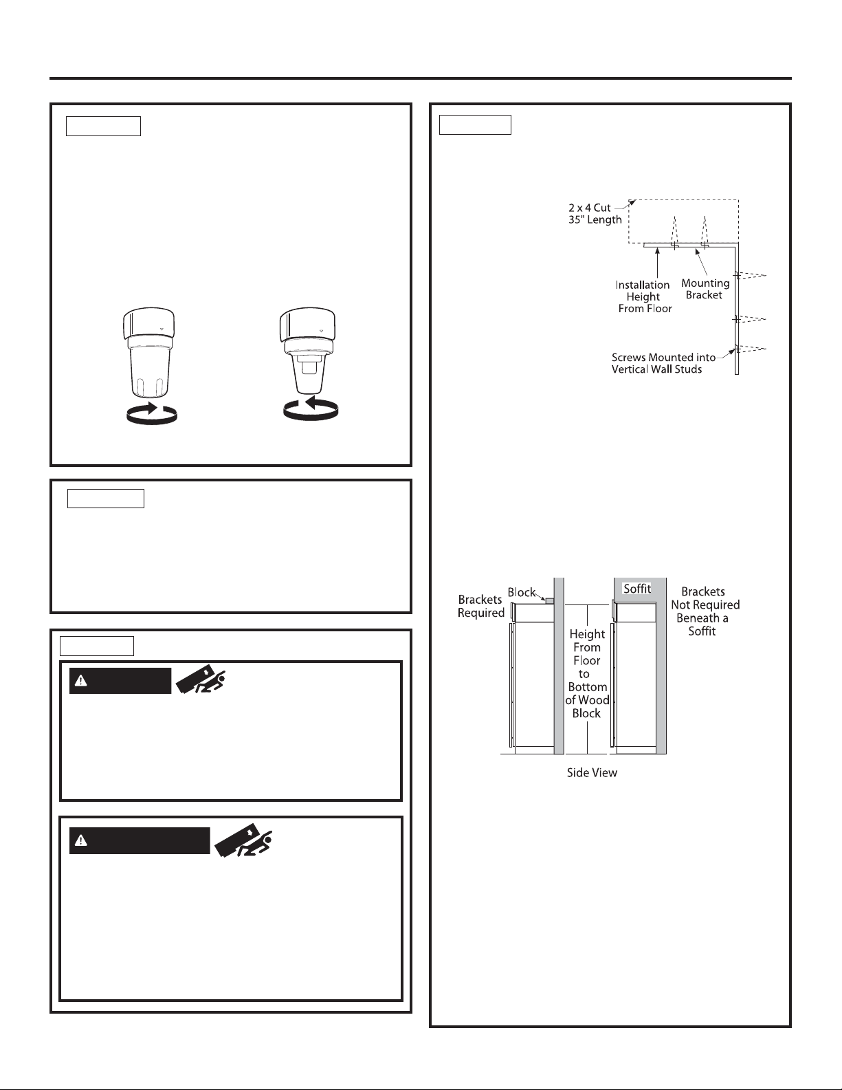
Rotate Counterclockwise
to Remove
Filter Bypass
Plug
STEP 5 INSTALL SIDE PANELS
Skip this step when not using side panels.
If you are using 1/4” (0.63 cm) side panels, they
should be inserted into the case trim. Fasten the
panels to the refrigerator with stick-on hook and loop
fastener strips before setting the refrigerator in place.
STEP 6 ANIT-TIP PROCEDURE (Cont.)
• Cut a 2” x 4” block, 35” (88.9 cm) long and secure
the block to the mounting brackets provided using
#12 or #14 wood screws.
• Secure the
bracket with
wood block to
the back wall
so that it is 84”
(213.36 cm)
from the finished
floor. Use #12
or #14 wood
screws. See the
illustration.
• The screws must
penetrate at least one inch into the vertical wall
studs.
• If metal wall studs, use self-tapping sheet metal
screws in place of wood screws.
IMPORTANT: When the refrigerator is installed under
a soffit or if there is not enough height for this method
of security, brackets cannot be used. Proceed to step
7 to level the refrigerator and then to step 8 to secure
refrigerator to cabinets.
secured to prevent tipping.
The refrigerator must be
STEP 6
WARNING
These refrigerators are top heavy, especially with
any doors open, and must be secured to prevent
tipping forward which could result in death or
serious injury. Read and follow the entire installation
instructions for securing the refrigerator with the antitip system.
AVERTISSEMENT
basculement
Ces réfrigérateurs présentent une partie supérieure
lourde, en particulier avec une porte ouverte; ils
doivent donc être fixés pour prévenir le basculement
vers l’avant et le risque concomitant de blessure
grave ou fatale. Lisez et suivez les instructions
d’installation complètes pour l’installation du système
anti-basculement.
ANTI-TIP PROCEDURE
Tip Over Hazard.
Risque de
Connect Power Cord:
• Before pushing the refrigerator into the opening,
plug the power cord into the receptacle. The water
filter guard will need to be removed for access
(some models). Remove the 3 screws holding it
in place. If access is still too tight, remove the 2
screws holding the water filter bracket and move
aside. Open the grille panel and reach into the
opening at the back to grasp the power cord. Pull
the power cord into the opening as you push the
refrigerator back. Secure the bracket and guard with
the original screws.
• Gently push refrigerator into the opening with hands
against front corners.
31-49171
15
Page 16
Installation Instructions - Standard Installation
STEP 7 LEVEL REFRIGERATOR
All models have 4-point leveling. The front is
supported by leveling legs, the rear is supported by
adjustable wheels. Both are accessible from the front
of the refrigerator.
• To level the back of the refrigerator, turn the 7/16”
hex nut located above the front wheels. Turn
clockwise to raise or counterclockwise to lower the
refrigerator.
• For front leveling, use a
1-1/4” open-end wrench.
• Adjust height of refrigerator
to match installation cutout
opening 84-1/2”
(214.63 cm). The refrigerator
should be level and plumb
with cabinetry.
NOTICE: The rear leveling wheels and front leveling
legs are limited to a maximum height adjustment of
1” (2.54 cm). If the installation requires more than
84-1/2” (214.63 cm) height, the installer should
elevate the refrigerator on a sheet of plywood or
runners. Cabinetry trim could also be added across
the top of the opening to shorten the opening. If you
attempt to raise the refrigerator more than 1”
(2.54 cm), you will damage the front leveling legs
and the rear leveling wheels. Make adjustments in
small increments.
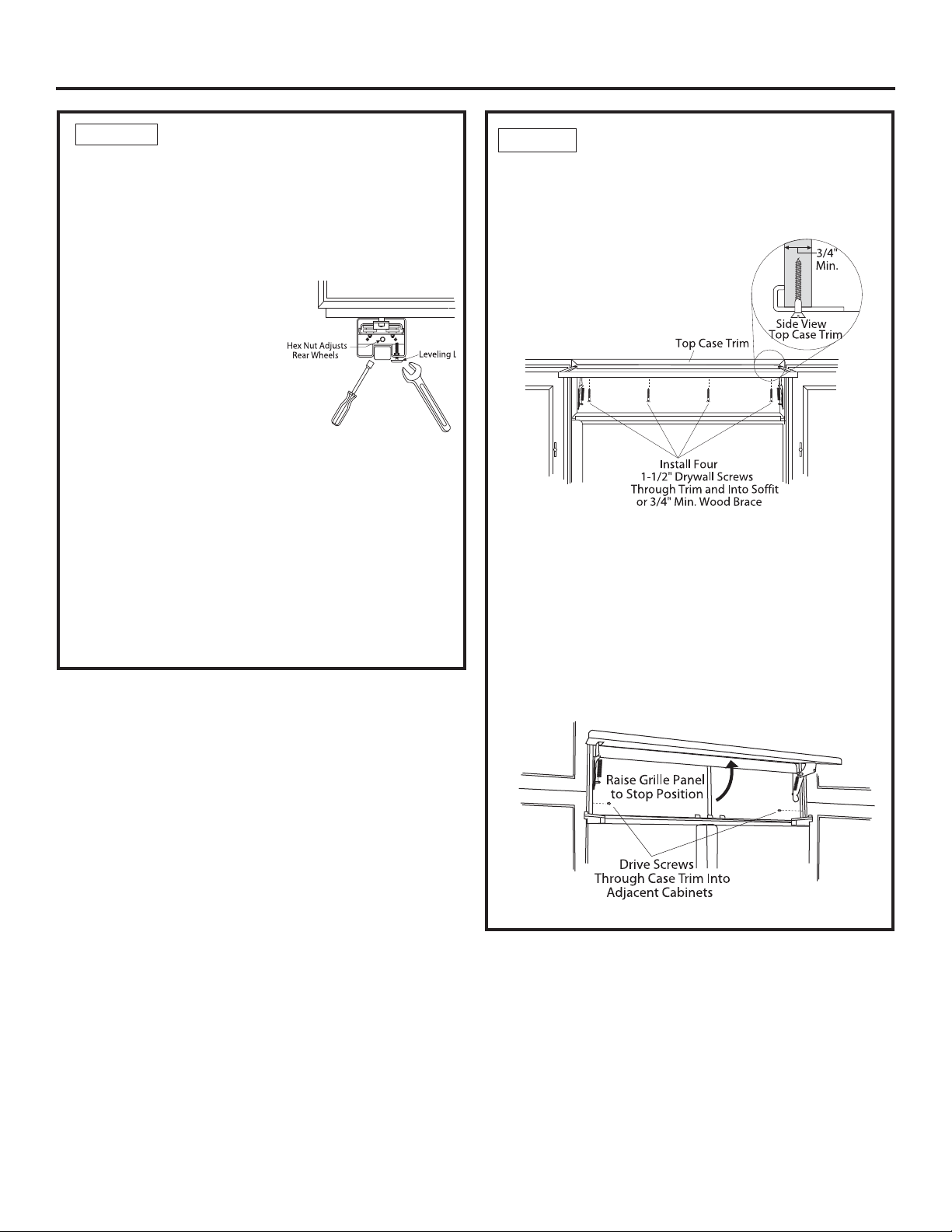
STEP 8 ALTERNATE ANTI-TIP
PROCEDURE
The refrigerator must be secured to prevent tipping.
• Raise the grille panel to access case trim.
• Use a 3/16” bit to drill four evenly spaced clearance
holes through the metal top case trim.
• Use a 1/16” bit to drill to pilot holes through the metal
clearance holes and into the wood soffit. The holes
should be centered in the soffit or a 3/4” (1.91 cm)
min. wood brace. The brace spanning the enclosure
must be securely fastened to cabinets on both sides.
• Install four, 1-1/2” drywall screws into the pilot holes.
• Drill screws into adjacent cabinets through side case
trim.
16
31-49171
Page 17

Installation Instructions - Standard Installation
STEP 9 ADJUST DOOR SWING
NOTE: This refrigerator has a 3-position door stop:
90°, 115°, and 130°. When space does not allow the
door to swing open fully to 115°, you may change
the door swing to a 90° opening. A 130° door swing
option is available for standard installation only. Skip
this step if door opening is satisfactory for your
installation situation.
• Open the door to view the bottom hinge. Note the
door stop pin locations. The pin is factory installed in
the 115° position.
• Close the door. From below, use pliers to unscrew
the door stop and reinstall into the 130° or 90°
position.
STEP 10 INSTALL GRILLE PANEL
To insert the framed or overlay panel into the
grille:
• Raise the grille panel to the stop position.
Loosen
Side
Trim
Screw
Adjust Nut Below
Spring to Accommodate
Panel Weight
• Loosen the screws on the side trim behind the frame.
Remove the bottom trim.
Loosen
Side
Trim
Screw
CAUTION
The metal panel may be slippery. Grip the metal
panel firmly so the panel does not slip out of the
frame and cause personal injury or damage to the
frame.
ATTENTION
ATTENTION AUX ARÊTES VIVES
Le panneau en métal peut bêtre glissant. Tenir
fermement le panneau en métal, de manière à ce
que le panneau ne glisse pas en dehors du cadre
en provoquant des blessures corporelles ou des
dommages au cadre.
• Slide the panel over the metal backer panel and into
the trim.
• If necessary, tap with a wood block until the panel
slips under the top trim piece.
• Reassemble the bottom trim. Tighten the screws.
• Adjust the hinge spring to accommodate the panel
weight, if necessary.
SHARP EDGE HAZARD
RISQUE DE COUPURE :
31-49171
17
Page 18

Installation Instructions - Standard Installation
STEP 11 INSTALL 1/4” (0.63 cm) FRAMED PANELS
Install door panels:
• Open the door to 90°. Remove the 6 Phillips head
screws from the door handle.
• Remove the handle. Retain all screws.
• Remove the 6 screws holding the trim, then lift off the
trim. Retain the screws.
• Slide the framed panel into the door trim.
Dispenser Models Only:
• The dispenser controls protrude beyond the face of the
freezer door. To avoid damage to the dispenser, the
trim at the top of the door should be removed.
• Remove the screws holding the top trim in place.
• Place the freezer panel into the bottom channel and
slide into the hinge side trim.
• Reinstall the top trim piece with screws.
Go to Step 12A for Overlay Panels
Supplied Handle
Shown in 1/4”
Panel Position
• There are two sets of holes in the handle side trim.
Replace the handle side trim by installing the original
screws in the FRONT screw holes.
• Secure the handle to the door using the REAR screw
holes.
• Follow the same procedures to install the opposite
panel.
• Check to be sure the handles are evenly aligned with
each other at the top. To adjust, loosen the handle
screws and slide up or down. Tighten the screws.
NOTE: Aluminum cover trim is supplied for use with
custom handles on overlay panels. It is not intended for
use with 1/4” (0.63 cm) panels. Discard the cover trim
when using 1/4” (0.63 cm) framed panels.
18
31-49171
Page 19

Installation Instructions - Standard Installation
STEP 11A INSTALL OVERLAY PANELS
Install door panels:
• Open door to 90°. Remove the 6 Phillips head screws
from the door handle.
• Remove the handle. Retain all screws.
• Remove the 6 screws holding the trim, then lift off the
trim. Retain the screws.
• Slide the overlay panel into the door trim.
Dispenser Models Only:
• The dispenser controls protrude beyond the face of
the freezer door. To avoid damage to the dispenser,
the trim at the top of the door should be removed.
• Remove the screws holding the top trim in place.
• Place the assembled freezer panel into the bottom
channel and slide into the hinge side trim.
• Reinstall the top trim piece with the screws.
• There are two sets of holes in the handle side trim.
Replace handle side trim by installing the original
screws in the REAR screw holes.
• Secure the handle to the door using the FRONT
screw holes.
• Follow the same procedures to install the opposite
panel.
• Check to be sure the handles are evenly aligned with
each other at the top. To adjust, loosen the handle
screws and slide up or down. Tighten the screws.
Supplied Handle
Shown in Overlay
Panel Position
31-49171
19
Page 20

Installation Instructions - Standard Installation
STEP 11A INSTALL OVERLAY PANELS
(continued)
Custom Handles
• If you are using custom handles, the handle must e
properly secured to the overlay panel before sliding
the panel into the trim.
• The cabinet manufacturer will supply the custom
handle and hardware.
• Discard the supplied handle.
Reinstall all original screws.
• Reinstall the handle side trim, using all 12 supplied
flat-head screws, plus the 12 flat-head screws
originally installed in the handle trim.
• Install a supplied end cap onto the top of the door,
using a Phillips head screwdriver and the 2 screws
provided. Hand-tighten the screws into the end
caps. Do not overtighten; damage will occur.
• Clean the aluminum trim with rubbing alcohol—
do not use alcohols with oil or lanolin that will prevent
adhesion of double-sided tape.
• Slip the aluminum cover onto the top bracket to check
the fit. The aluminum cover trim has a slot on each
end which fits the bracket.
STEP 11A INSTALL OVERLAY
PANELS (continued)
• Carefully place the aluminum cover trim onto the top
bracket so that the bracket is inside the cover trim.
Use the top to bottom grooves along the handle side
to align the cover trim accurately. Align the bracket
with the screw holes in the top of the door. Pull the
tape a few inches at a time while pressing the trim
against the door. Press and hold approximately 10
seconds before continuing along the length of the
door.
• Install another bracket at the bottom of the door to
secure the cover trim. Use a stubby Phillips head
screwdriver and the 2 screws provided.
• NOTE: Make sure there are no gaps in the
installation.
• Follow the same procedure on the opposite door.
STEP 12 CONNECT WATER SUPPLY
Refrigerator
Water Supply
House
Water Supply
Top Bracket
Slide aliminum
trim over top
bracket.
Top Bracket
Secure top
bracket with
2 screws.
• Remove the trim. Peel away a few inches of the
adhesive backing.
IMPORTANT: The tape is very sticky and strong.
Once it adheres to a surface, it cannot be removed
without damaging both surfaces. Do not install the
trim before the final wood panels are in place. Be
sure to align the trim carefully before removing the
paper backing.
• Locate and bring the tubing to the front of the
cabinet.
• Turn the water on to flush debris from the line. Run
about a quart of water through the tubing into a
bucket, then shut off the water.
Copper Tubing:
• Slip a 1/4” nut and ferrule (provided) over both ends
of the copper tubing. Insert the tube into the union
fitting on the unit and tighten the nut to the union.
• Turn on the water to check for leaks.
SmartConnect™ Tubing:
NOTE: The only Monogram-approved plastic tubing
is supplied in the SmartConnect™ Refrigerator Tubing
kits. Do not use any other plastic water supply line
because the line is under pressure at all times. Other
types of plastic may crack or rupture with age and
cause water damage to your home.
20
31-49171
Page 21

Installation Instructions - Standard Installation
STEP 12 CONNECT WATER SUPPLY
(continued)
SmartConnect™ Refrigerator Tubing Kits are available
in the following lengths:
2’ (.6 m) WX08X10002
8’ (2.4 m) WX08X10006
15’ (4.6 m) WX08X10015
25’ (7.6 m) WX08X10025
• Insert the molded end of the tubing into the
refrigerator connection. Tighten the compression nut
until it is just hand tight.
• Tighten one additional turn with a wrench.
Overtightening can cause leaks!
• Turn on the water to check for leaks.
NOTE: Make sure excess tubing length does not
interfere with the toekick installation.
STEP 13 CONNECT POWER, CLOSE
GRILLE PANEL
• Open the grille panel.
• Plug in the power cord (if necessary) by reaching
into the opening next to the water filter. The water
filter guard will need to be removed for access (some
models). Remove the 3 screws holding it in place. If
access is still too tight, remove the 2 screws holding
the water filter bracket and move aside. Plug in the
power cord. Secure the bracket and guard with the
original screws.
Screws
Bracket
Screws
Water Filter
Guard in Front of
Electric Outlet
Access
STEP 14 START ICEMAKER
CAUTION
of the ejector mechanism, or with the heating element
(located on the bottom of the icemaker) that releases
the cubes. Do not place fingers or hands on the
automatic ice making mechanism while the refrigerator
is plugged in.
ATTENTION
pièces mobiles du mécanisme d’éjection ou l’élément
chauffant (situé dans le bas de la machine à glaçons)
qui libère les cubes. Ne placez pas les doigts ou
les mains sur le mécanisme de production de glace
automatique lorsque le réfrigérateur est branché dans
la prise électrique.
• Slide the power switch to ON.
• The icemaker will begin operation automatically.
• Be sure nothing interferes with the sweep of the feeler
arm.
• Discard the first full bucket of ice cubes.
• To turn the icemaker off, slide the switch to OFF.
Avoid contact with the moving parts
Évitez tout contact avec les
Icemaker
Power
Switch
Feeler Arm
STEP 15 INSTALL TOEKICKS
• Locate the supplied toekicks (shipped taped to the
side of the refrigerator.
• The narrower set of toe kicks will be used with
standard installation. You can discard the other set of
toe kicks.
• Attach the LARGER toekick to the refrigerator using
ONLY the top center hole (1).
• Attach the toekick skirt to the refrigerator using the
three lower slots (2).
• Check to make sure power to refrigerator is on by
opening refrigerator door to see if interior lights are on.
• The temperature controls are preset at 37°F (3° C) for
the fresh food section and 0°F (-18°C) for the freezer.
• Allow 24 hours to stabilize before making adjustments.
31-49171
1
2
• A custom toekick can be installed to match or
complement the surrounding cabinetry. Use the
supplied toekick as a template to cut the shape.
21
Page 22

Installation Instructions - Standard Installation
INSPECT FINAL INSTALLATION
Check door alignment. Stand back away from the
refrigerator to inspect the final installation.
• Check to be sure the handles are evenly aligned with
each other at the top. To adjust, loosen the handle
screws and slide up or down. Tighten the screws.
• Shipping or the addition of heavy door panels may
have caused the doors to move slightly out of
alignment.
Door Out of
Alignment
Bushing
Door Hinge
Case Hinge
Raise
• If necessary, the fresh food door may be adjusted
up or down to align with the freezer door.
• Use a 5/16” wrench to adjust the hinge pin as
shown.
5/16" Wrench
22
31-49171
Page 23

Instructions for Flush Installation
31-49171
23
Page 24

Design Guide - Flush Installation
THE INSTALLATION SPACE
36" Models 12"
42" Models 19"
48" Models 22-1/4"
*Finished Width
6"
85" max
Finished
Opening
*Finished cutout width must be:
39” (99.06 cm) for 36” models
45” (114.3 cm) for 42” models
51” (129.54 cm) for 48” models
Water And Electrical Locations
The opening must be prepared with the electrical and
the cold water supply located as shown.
The Cutout Depth Must Be 26-3/16” (66.99 cm)
Wooden cleats are required for flush installation. See
Side Cleats on page 27. If 3/4” (1.91 cm) Overlay
panels w/ 90 degree door swing are to be used
then cutout depth must be 26-1/4” (66.68 cm)
Additional Specifications
• A 115 volt 60Hz., 15 or 20 amp power supply is
required. An individual properly grounded branch
circuit or circuit breaker is recommended. Install
a properly grounded 3-prong electrical receptacle
recessed into the back wall. Electrical must be
located on the rear wall as shown.
• The water line can enter the opening through the
floor or back wall. The water line should be 1/4”
O.D. copper tubing or SmartConnect™ kit between
the cold water line and water connection location,
long enough to extend to the front of the refrigerator.
Installation of an easily accessible shut-off valve in
the water line is required.
Electrical
Area
26-3/16"
7"
Water Supply
3 1/2"
5"
75" From Floor
to Bottom
of Electrical
Area
7"
3 1/2"
DIMENSIONS AND CLEARANCES
35", 41", or 47"
Case Width
83-1/2"
at
Rear
36", 42" or 48"
Frame to Frame
Depth Including Handles 26-7/8”
Product Clearances
These refrigerators are equipped with a 3-position door
stop. The factory-set 115° door swing can be adjusted
to 90° if clearance to adjacent cabinets or walls is
restricted. Only standard installation can be adjusted to
130°.
115° Door Swing
A
Models A B C
36” 13”
42” 13” (33.02 cm) 19” (48.26 cm) 26-5/8” (67.63 cm)
48” 15” (38.1 cm) 20” (50.8 cm) 28-5/8” (72.71 cm)
(33.02 cm) 15” (38.1 cm) 20-5/8” (52.39 cm)
Allow minimum clearances for the freezer door
(Dimension A) and fresh food door (Dimension B) for
a full 115° door swing and to allow for pan removal.
25-3/8" Framed Models
* Shipping height.
*84"
From
Floor
90° Door Swing
B
The refrigerator can
be adjusted to fit
into a cutout that is
85” (215.9 cm) in
height. Use leveling
legs and wheels
for a maximum 1”
(2.54 cm) height
adjustment.
23-7/8"
Behind
Frame
C
*Min. Distance
to Wall
*4” Stainless and
Trimmed Models.
5” Pro Series
For a 90° door swing, allow 4” (10.16 cm) min.
clearance to a wall, for framed and stainless steel
models. Allow 5” (12.7 cm) min. clearance for
professional series models. If the 90° door stop
position is used, pan access is maintained, but pan
removal is restricted.
24
31-49171
Page 25

Design Guide - Flush Installation
CUSTOMIZATION BASICS:
These refrigerators are designed to be customized with decorative panels. Field installed custom door and grille
panels are required.
Optional Accessory Kits
ZKHSS2: Monogram Tubular Stainless Steel handles
designed to fit 3/4” (1.91 cm) overlay panels.
ZKHPSS1: Professional Tubular Stainless Steel
handles designed to fit 3/4” (1.91 cm) overlay panels.
Kit includes one handle. Order 2 kits for side-by-side
refrigerator models from your Monogram supplier
ZUG2: For side-by-side installation of two trimmed
models. This kit provides for the installation of a unified
custom grille panel to span the width of two units using
a framed or overlay panel.
CUSTOM HANDLE DESIGN GUIDE
Custom handles must be used for flush installation. For
custom handle installation, counterbore holes in rear of
decorative panels must ensure 1/2” (1.27 cm) material
thickness remains for handle support.
NOTE: The counterbore must not exceed 1” (2.54 cm)
in diameter.
1/2”
1/4”
3/4”
REFRIGERATOR LOCATION
• Do not install the refrigerator where the
temperature will go below 55°F (13°C). It
will not run often enough to maintain proper
temperatures.
• Do not install the refrigerator where temperatures
will go above 100°F (37°C). It will not perform
properly.
• Do not install the refrigerator in a location
exposed to water (rain, etc.) or direct sunlight.
• Install it on a floor strong enough to support it
fully loaded.
Minimum distance from handle
side edge to handle center
should be 1-1/4” (3.18 cm) as
shown.
7/8"
0.85"
1/2"
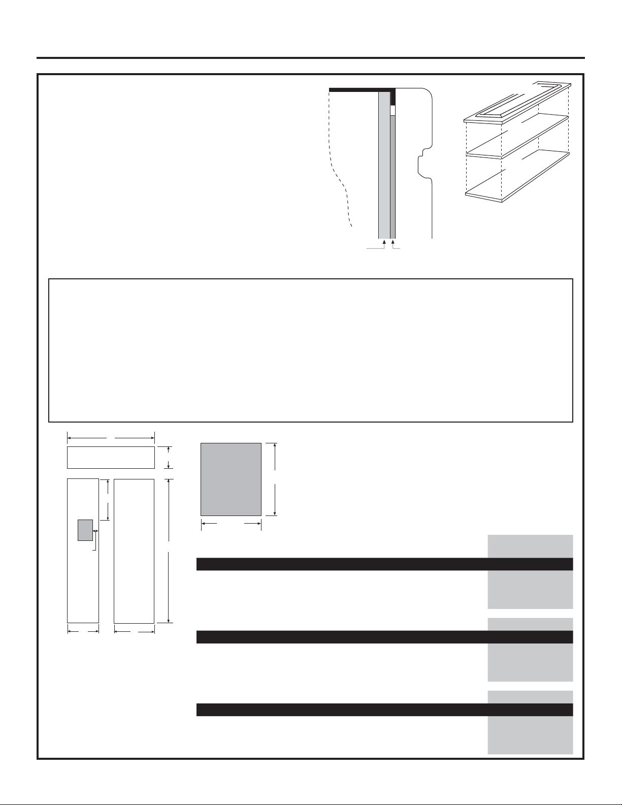
SIDE PANELS
Side panels must be used
whenever the sides of
the refrigerator will be
exposed. The 1/4”
(0.63 cm) side panels will
slip into the side case trim.
Secure the panels to the
refrigerator with stick-on
hook and loop fastener
strips. Order the side
panels from the cabinet
manufacturer.
• Cut a notch in the top
front corner as shown
to allow clearance for
corner keys in the front
side trim.
1-1/4”1-1/4”
24"
3/16"
1-7/8"
*84"
*3" to 4"
2-9/16"
* Depending on installation height.
31-49171
25
Page 26

Design Guide - Flush Installation
1/2"
Overlay
Panel
1/4"
Backer
Panel
Door
.10"
Spacer
D
1/2” (1.27 cm) OVERLAY PANEL DIMENSIONS
For a more custom appearance, overlay panels may be installed on trimmed models. The
overlay panel must be secured to a 1/4” (0.63 cm) thick backer panel which slides into the
trim. A spacer panel 0.10” (0.25 cm) thick must be placed between the overlay and backer
panel.
Assemble the panels with glue and screws:
• Center the spacer panel on the backer panel, left to right and top to bottom. Secure the
panels with glue.
• Refer to the following chart for locating the backer panel to the overlay panel. Secure the
overlay panel to the backer panel with glue and screws. Screws must be countersunk into
the backer panel.
Hinge Side
C
Freezer
Back
Backer with
Overlay Panel
Assembly
C
Fresh Food
Back
SxS Fresh Food 2-1/16” 1/16” 1/8” 1/8”
D
D
SxS Freezer 2-1/16” 1/16” 1/8” 1/8”
SxS Grille 2-1/16” 2-1/16” 1-15/32”* 7/32”
A
AB
B
IMPORTANT NOTE – DISPENSER MODELS
The refrigerator is supplied with 3 dispenser trims; 2
for standard installation and 1 for flush installation. The
flush installation trim is designed to fit a total panel
thickness of 0.85” (2.16 cm) or 0.75” (1.91 cm).
• If the panel is less than 0.75” (1.91 cm) a noticeable
gap may be created around the dispenser trim.
• If the panel is more than 0.85” (2.16 cm) the dispenser
.250” + .10” + .50” = .85”
0.63 + 0.25 + 1.27 = 2.16 cm
Total Panel Thickness
Grille Back
C
A B
AB CD
*2” for 36” models
trim cannot be secured to the door.
• The overlay panel must be constructed according to
the specifications shown to achieve the correct total
thickness.
• Cut the dispenser opening after the backer, spacer
and overlay panels have been assembled.
See Dispenser Trim Fit Example, page 28.
Panel Dimensions
36” Side-by-Side Fresh Food Freezer Grille Dispenser Cutout Position
E
1/4” Backer Panel 68-3/8” x 18-9/16” 68-3/8” x 14-9/16” 33-7/8” x 9”
.10” Spacer Panel 67” x 17-9/16” 67” x 13-9/16” 33” x 8-3/8”
EF
1/2” Overlay Panel 68-5/8” x 20-7/8” 68-5/8” x 16-7/8” 38” x 11-3/16” 17-23/32” 3-3/8”
15-3/8”
F
42” Side-by-Side Fresh Food Freezer Grille Dispenser Cutout Position
1/4” Backer Panel 68-3/8”x 24-9/16” 68-3/8” x 14-9/16” 39-7/8” x 9-1/2”
.10” Spacer Panel 67” x 23-9/16” 67” x 13-9/16” 39” x 8-5/8”
EF
1/2” Overlay Panel 68-5/8” x 26-7/8” 68-5/8” x 16-7/8” 44” x 11-3/16” 17-23/32” 3-3/8”
9-5/8”
48” Side-by-Side Fresh Food Freezer Grille Dispenser Cutout Position
1/4” Backer Panel 68-3/8” x 26-9/16” 68-3/8” x 18-9/16” 45-7/8” x 9-1/2”
.10” Spacer Panel 67” x 25-9/16” 67” x 17-9/16” 45” x 8-5/8”
EF
1/2” Overlay Panel 68-5/8” x 28-7/8” 68-5/8” x 20-7/8” 50” x 11-3/16” 17-23/32” 5-3/8”
IMPORTANT NOTE: Maximum total weight for the assembled panels:
• Fresh food door panel – 75 lbs.(34 kg) • Freezer door panel – 53 lbs.(24 kg) • Grille Panel – 18 lbs. (8.16 kg)
26
31-49171
Page 27

Design Guide - Flush Installation
3/4” (1.91 cm) RAISED PANEL DIMENSIONS
For a more custom appearance raised panels may be installed
on trimmed models. The panels must be 3/4” (1.91 cm) thick
at and routed per the instructions below in order to guarantee
proper operation
IMPORTANT NOTE – DISPENSER MODELS
The refrigerator is supplied with 3 dispenser trims; 2 for
standard installation and 1 for flush installation. The overlay
dispenser trim is designed to fit a total panel thickness of 0.85”
(2.16 cm) or 0.75” (1.91 cm).
• If the panel is less than 0.75” (1.91 cm) a noticeable gap may
be created around the dispenser trim.
• If the panel is more than 0.85” (2.16 cm) the dispenser trim
cannot be secured to the door.
• The overlay panel must be constructed according to the
specifications shown to achieve the correct total thickness.
See Dispenser Trim Fit Example, page 30.
Panel Dimensions
Door
3/4"
Raised
Panel
15-3/8”
36” Side-by-Side Fresh Food Freezer Grille Dispenser Cutout Position
E
3/4” Raised Panel 68-5/8” x 20-7/8” 68-5/8” x 16-7/8” 38” x 11-3/16” 17-23/32” 3-3/8”
42” Side-by-Side Fresh Food Freezer Grille Dispenser Cutout Position
F
3/4” Raised Panel 68-5/8” x 26-7/8” 68-5/8” x 16-7/8” 44” x 11-3/16” 17-23/32” 3-3/8”
48” Side-by-Side Fresh Food Freezer Grille Dispenser Cutout Position
3/4” Raised Panel 68-5/8” x 28-7/8” 68-5/8” x 20-7/8” 50” x 11-3/16” 17-23/32” 5-3/8”
9-5/8”
WARNING
E F
E F
E F
IMPORTANT NOTE: Maximum total weight
for the assembled panels:
• Fresh food door panel – 75 lbs. (34 kg)
• Freezer door panel – 53 lbs. (24 kg)
• Grille Panel – 18 lbs. (3.16 kg)
AVERTISSEMENT
Door Trim Pinch Point Hazard
Improper installation can lead to a finger pinch point
hazard between the side door trim and the cabinets
when operating the door, especially with children.
To minimize this risk you must follow the installation
instructions for cabinet dimensions, trim assembly,
and door stop angle.
31-49171
Risque de pincement de la garniture de porte
Une installation incorrecte représente un risque de pincement
pour les doigts entre le côté de la garniture de porte et les
armoires lors de l’ouverture ou de la fermeture de la porte,
spécialement pour les enfants. Pour réduire ce risque, vous
devez suivre les instructions d’installation selon les dimensions
des armoires, l’assemblage de garniture et l’angle de butée de
la porte.
27
Page 28

Design Guide - Flush Installation
3/4” (1.91 cm) RAISED DOOR PANEL ROUTING
For 3/4” (1.91 cm) raised door panel, routing is required. The router depth is 1/4” (0.63 cm) all the way around the
panel back. Additional panel width reductions are required per the diagrams below. This will create a “picture frame”
routing that will slide onto the attached door trim.
Back
TOP DETAIL TOP
3/4”
11/32”
1/4”
Front
3/32”
DETAIL BOTTOM
1/4”
11/32”
NOTE: Routed areas should be
finished as they may be visible
when assembled.
Front
Back
CORNER VIEW SHOWING
“PICTURE FRAME” ROUTING
DETA
IL HANDLE
SIDE
HANDLE
SIDE
BOTTOM
3/4” PANEL SIDE VIEW
(AFTER ROUTING)
DETAIL HINGE
SIDE
HINGE
SIDE
ROUTER DEPTH 1/4”
2-1/16”
3/4” PANEL BOTTOM VIEW
3/16”
Front
Back
(AFTER ROUTING)
NOTE: For panels constructed with rails and stiles (5-panel), the minimum width is 3” (7.62 cm) for rails and 4” (10.16 cm)
for stiles.
28
31-49171
Page 29

Design Guide - Flush Installation
3/4” (1.91 cm) RAISED GRILLE PANEL ROUTING
For 3/4” (1.91 cm) raised grille panel, routing is required. The router depth is 1/4” (0.63 cm) all the way around the
panel back. Additional panel width reductions are required per the diagrams below. This will create a “picture frame”
routing that will slide onto the attached grille trim.
DETAIL TOP
TOP
NOTE: Routed areas should be
finished as they may be visible
when assembled.
Front
Back
Back
Front
1-1/2”
2” for 36”
models
ROUTER DEPTH 1/4”
BOTTOM
3/4” PANEL SIDE VIEW
(AFTER ROUTING)
LEFT
SIDE
DETAIL
LEFT SIDE
CORNER VIEW SHOWING
“PICTURE FRAME” ROUTING
3/16”
DETAIL BOTTOM
DETAIL RIGHT
SIDE
ROUTER DEPTH 1/4” ROUTER DEPTH 1/4”
2-1/16” 2-1/16”
Front
RIGHT
SIDE
Back
3/4” PANEL BOTTOM VIEW
(AFTER ROUTING)
NOTE: For panels constructed with rails and stiles (5-panel), the minimum width is 3” (7.62 cm) for rails and 4” (10.16 cm)
for stiles.
29
31-49171
Page 30

Design Guide - Flush Installation
DISPENSER TRIM FIT EXAMPLES:
(NOT TO SCALE)
CUSTOM PANEL
• The dispenser trim fits over the custom
panel and snaps into the freezer door.
SIDE CLEATS
Wood cleats are required to be installed vertically
down both sides of the cabinet opening to provide
depth stop for the refrigerator when installed into the
opening.
The cleat should be installed per the diagrams below
based on the type of panel being used.
TOP VIEW
Finished
Cleat
Custom Panel
FREEZER DOOR
Ice / Water Dispenser
3/4”Overlay Dispenser Trim
5-1/4”
Finished
Cleat
5-3/8”
DOOR
3/4” Panel
Case Trim
TOP VIEW
DOOR
1/2” Panel
Case Trim
1/2”
1/2”
30
31-49171
Page 31

Installation Instruction - Flush Installation
TOOLS AND MATERIALS REQUIRED
• Tinsnips to cut banding
• Stepladder
• 1” Bit extension
• Tape measure
• Gloves
• 1/4” Drywall screws
• 5-Gal. Bucket with cover
• 6” Spirit level
• Appliance hand truck
• Tubing cutter
• 7/16” open-end wrench
• #2 Phillips screwdriver
• Drill and appropriate bits
• 5/16”, 7/16” socket
• Safety glasses
• 1-1/8” open end wrench
• Pliers
• 1/4”, 5/16” Combo Rachet
• 35” long 2x4 for Anti-Tip support
• 1/4” copper water line tubing or SmartConnect™
Refrigerator Tubing kits
• Water shut-off valve
• Custom panels for doors and grille panel
• Screws to secure refrigerator to cabinetry
• Stick-on hook and loop fastener strips for 1/4” side
panels
HARDWARE SUPPLIED
• Water filter bypass plug
• Toekick
• 1/4” nut and ferrule
• Dispenser trim for overlay panels (for use with
Custom Panel models).
•
Flush inset case trim
FLOORING
For proper installation, this refrigerator must be placed
on a level surface of hard material that is at the same
height as the rest of the flooring. This surface should
be strong enough to support a fully loaded refrigerator,
or approximately 1,500 lbs.(680.39 kg).
NOTE: Protect the finish of the flooring. Cut a large
section of the cardboard carton and place under the
refrigerator where you are working.
GROUNDING THE REFRIGERATOR
WARNING
Failure to follow these instructions can result in death,
fire, or electrical shock.
The power cord of this appliance is equipped with a
3-prong (grounding) plug which mates with a standard
3-prong (grounding) wall receptacle to minimize the
possibility of electric shock hazard from this appliance.
Have the wall outlet and circuit checked by a qualified
electrician to make sure the outlet is properly grounded.
Where a standard 2-prong wall outlet is encountered,
it is your personal responsibility and obligation to have
it replaced with a properly grounded 3-prong wall outlet.
DO NOT, UNDER ANY CIRCUMSTANCES, CUT OR
REMOVE THE THIRD (GROUND) PRONG FROM
THE POWER CORD.
DO NOT USE AN ADAPTER PLUG TO CONNECT
THE REFRIGERATOR TO A
2-PRONG OUTLET.
DO NOT USE AN EXTENSION
CORD WITH THIS APPLIANCE.
Electrical Shock Hazard.
MISE À LA TERRE DU RÉFRIGÉRATEUR
AVERTISSEMENT
électrique.
Le non-respect de ces instructions peut entraîner des
risques d’incendies, des chocs électriques ou la mort.
Le cordon d’alimentation de cet appareil est équipé
d’une fiche à trois broches (pour une mise à la terre)
qui s’adapte à la prise de courant standard à 3 broches
(pour une mise à la terre) pour minimiser les risques de
chocs électriques par cet appareil.
Faites vérifier la prise murale et le circuit électrique par
un électricien qualifié pour s’assurer que le système est
correctement mis à la terre.
Dans le cas d’une prise biphasée, l’installateur a la
responsabilité et l’obligation de la remplacer par une
prise triphasée correctement mise à la terre.
NE COUPEZ PAS OU N’ENLEVEZ PAS, SOUS
AUCUN PRÉTEXTE, LA TROISIÈME BROCHE DE
MISE À LA TERRE DU CORDON
D’ALIMENTATION.
N’UTILISEZ PAS D’ADAPTATEUR
POUR BRANCHER LE
RÉFRIGÉRATEUR À UNE PRISE
BIPHASÉE.
N’UTILISEZ PAS DE RALLONGE AVEC CET
APPAREIL.
Risque de choc
31-49171
31
Page 32

Installation Instructions - Flush Installation
STEP 1 REMOVE PACKAGING
WARNING
The refrigerator is much heavier at the top than at the
bottom—be careful when moving. When using a hand
truck, handle from the side only.
AVERTISSEMENT
basculement Le réfrigérateur est beaucoup plus
lourd en haut qu’en bas. Il faut être prudent lors des
déplacements. Si un diable est utilisé, il faut soulever
le réfrigérateur sur le côté seulement.
• Carefully cut banding at the top and bottom, remove
the outer carton.
• Slide out the back corner posts (2).
• Slide the carton off the top of the cabinet.
NOTE: IT IS NOT NECESSARY TO LAY THE
CABINET DOWN IN ORDER
TO REMOVE THE SKID!
• The unit is secured to the
skid with 4 slotted tie-down
straps. Remove the six
7/16” bolts from the base
channels in the tie-downs.
• Remove the six 7/16” bolts
securing the straps to the
skid.
NOTE: DO NOT ATTEMPT
TO ROLL UNIT OFF SKID.
• The support blocks on the
bottom of the refrigeration case must be removed
before the refrigerator is taken off the skid or
damage will occur. Carefully tilt the refrigerator and
slide the blocks out from beneath.
• Remove the toekick and set aside for final
installation.
• Lift the refrigerator off the skid with an appliance
dolly. Handle from the sides.
Tip Over Hazard.
Risque de
Remove
Toekick
Tie Downs
STEP 2 MOVE THE REFRIGERATOR
INTO THE HOUSE
• Re-use the corner posts from the packaging to
protect stainless steel models. Run the appliance
dolly straps over the posts and under the handles.
• Leave the protective film on the refrigerator until
installation is complete. IMPORTANT: Never lift the
refrigerator by the handle or push against the grille
panel; this could cause damage or misalignment.
• Avoid laying the unit on its back or side to prevent
sealed system restrictions.
STEP 3 INSTALL WATER LINE
WARNING
AVERTISSEMENT
alimentation d’eau potable seulement.
• A cold water supply is required for automatic icemaker
operation. The water pressure must be between 40
and 120 p.s.i. (275-827 kPa).
• Route 1/4” OD copper or SmartConnect™ plastic
tubing between house cold water line and the water
connection location.
• The tubing should be long enough to extend to the
front of the refrigerator. Allow enough tubing to
accommodate the bend leading into the water line
connection.
NOTE: The only Monogram approved plastic tubing
is supplied in the SmartConnect™ Refrigerator Tubing
kits. Do not use any other plastic water supply line
because the line is under pressure at all times. Other
types of plastic may crack or rupture with age and
cause water damage to your home.
SmartConnect™ Refrigerator Tubing Kits are available
in the following lengths:
2’ (.6 m) WX08X10002
8’ (2.4 m) WX08X10006
15’ (4.6 m) WX08X10015
25’ (7.6 m) WX08X10025
Shut off the main water supply.
Turn on the nearest faucet long enough to clear the line
of water.
• Install a shut-off valve between the icemaker water
valve and cold water pipe in a basement or cabinet.
The shut-off valve should be located where it will be
easily accessible.
• Turn on the main water supply and flush debris.
Run about a quart of water through the tubing into a
bucket. Shut off the water supply at the shut-off valve.
NOTE: Saddle type shut-off valves are included in
many water supply kits. Before purchasing, make sure
a saddle type valve complies with your local plumbing
codes.
NOTE: Commonwealth of Massachusetts Plumbing
Codes 248CMR shall be adhered to. Saddle valves
are illegal and use is not permitted in Massachusetts.
Consult with your licensed plumber.
Connect to potable water supply
only.
Raccordez l’appareil à une
Floor
Cold Water Line
32
31-49171
Page 33

Installation Instructions - Flush Installation
STEP 4 INSTALLATION WITH
HOUSEHOLD WATER
FILTRATION SYSTEM
Skip this step if you do not have a household water
filtration system
If the water supply to the refrigerator is from any
household water filtration system, the filter cartridge
should be removed. For better ice and water performance,
remove the filter and install the filter bypass plug.
Rotate Counterclockwise To
Remove
Filter Bypass
Plug
STEP 5 INSTALL SIDE PANELS
Skip this step when not using side panels.
If you are using 1/4” (0.63 cm) side panels, they should
be inserted into the case trim. Fasten the panels to the
refrigerator with stick-on hook and loop fastener strips
before setting the refrigerator in place.
STEP 7 ANTI-TIP PROCEDURE
WARNING
These refrigerators are top heavy, especially with any
doors open, and must be secured to prevent tipping
forward which could result in death or serious injury.
Read and follow the entire installation instructions for
securing the refrigerator with the anti-tip system.
AVERTISSEMENT
basculement
Ces réfrigérateurs présentent une partie supérieure
lourde, en particulier avec une porte ouverte; ils
doivent donc être fixés pour prévenir le basculement
vers l’avant et le risque concomitant de blessure
grave ou fatale. Lisez et suivez les instructions
d’installation complètes pour l’installation du système
anti-basculement.
• Cut a 1” x 4” block, 35” (88.9 cm)
long.
• Measure and mark under the soffit,
5-1/4” (13.34 cm) from the front edge
of the cabinet.
• Secure the wood block under the
soffit. From the bottom of the block to
the finished floor should measure 84”
(213.36 cm). See the illustration.
Tip Over Hazard.
Risque de
STEP 6 INSTALL CASE TRIM
The unit arrives with case trim for standard installation
attached. Flush installation case trim is provided.
Remove the three pieces of factory installed case
trim (both sides and top). Install new case trim using
supplied right hand and left hand case trim pieces
and case trim screws. A top piece of case trim is not
required for flush installation. Attach case trim to each
side of case as shown in illustration using case trim
screws in holes provided down each side of the case.
Connect Power Cord:
• Before pushing the refrigerator into the opening, plug
the power cord into the receptacle. The water filter
guard will need to be removed for access (some
models). Remove the 3 screws holding it in place. If
access is still too tight, remove the 2 screws holding
the water filter bracket and move aside. Open the
grille panel and reach into the opening at the back
to grasp the power cord. Pull the power cord into the
opening as you push the refrigerator back. Secure the
bracket and guard with the original screws.
• Gently push refrigerator into the opening with hands
against front corners.
• Once the refrigerator is pushed into the opening,
use leveling legs to raise the refrigerator until it rests
against the block installed at the top of the opening.
31-49171
33
Page 34

Installation Instructions - Flush Installation
STEP 7 ANIT-TIP PROCEDURE
(continued)
We recommend units for flush installation be
installed under a soffit. If this is not possible, follow
these instructions using the mounting brackets.
• Cut a 2” x 4” block, 35” (88.9 cm) long and secure the
block to the mounting brackets provided using #12 or
#14 wood screws.
• Secure the bracket with wood block to the back wall
so that it is 84” (213.36 cm) from the finished floor.
Use #12 or #14 wood screws. See the illustration.
• The screws must
penetrate at least
one inch into the
vertical wall studs.
• If metal wall studs
then use selftapping sheet metal
screws in place of
the wood screws
to secure the block
and brackets to the
wall.
STEP 8 LEVEL REFRIGERATOR
All models have 4-point leveling. The front is supported
by leveling legs, the rear is supported by adjustable
wheels. Both are accessible from the front of the
refrigerator.
• To level the back of the refrigerator, turn the 7/16”
hex nut located above the front wheels. Turn
clockwise to raise or
counterclockwise to lower
the refrigerator.
• For front leveling, use a
1-1/4” open-end wrench.
• Adjust height of refrigerator
to match installation cutout
opening 84-1/2”
(214.63 cm). The refrigerator
should be level and plumb
with cabinetry.
NOTICE: The rear leveling wheels and front leveling
legs are limited to a maximum height adjustment of 1”
(2.54 cm). If the installation requires more than 84-1/2”
(214.63 cm) height, the installer should elevate
the refrigerator on a sheet of plywood or runners.
Cabinetry trim could also be added across the top of
the opening to shorten the opening. If you attempt
to raise the refrigerator more than 1” (2.54 cm),
you will damage the front leveling legs and the
rear leveling wheels. Make adjustments in small
increments.
34
31-49171
Page 35

Installation Instructions - Flush Installation
STEP 9 ADJUST DOOR SWING
NOTE: This refrigerator has a 3-position door stop.
When space does not allow the door to swing open
fully to 115°, you may change the door swing to a
90° opening. A 130° door swing option is available
for standard installation only. Skip this step if door
opening is satisfactory for your installation
situation.
• Open the door to view the bottom hinge.
Note the door stop pin locations. The pin is factory
installed in the 115° position.
• Close the door. From below, use pliers to unscrew
the door stop and reinstall into the 90° position.
WARNING
Door Trim Pinch Point Hazard
Improper installation can lead to a finger pinch point
hazard between the side door trim and the cabinets
when operating the door, especially with children.
To minimize this risk you must follow the installation
instructions for cabinet dimensions, trim assembly,
and door stop angle.
AVERTISSEMENT
Risque de pincement
de la garniture de porte
Une installation incorrecte représente un risque
de pincement pour les doigts entre le côté de la
garniture de porte et les armoires lors de l’ouverture
ou de la fermeture de la porte, spécialement pour les
enfants. Pour réduire ce risque, vous devez suivre
les instructions d’installation selon les dimensions
des armoires, l’assemblage de garniture et l’angle de
butée de la porte.
31-49171
35
Page 36

Installation Instructions - Flush Installation
STEP 10 INSTALL GRILLE PANEL
To insert the framed or overlay panel into the grille:
• Raise the grille panel to the stop position.
Loosen
Side
Trim
Screw
Adjust Nut Below
Spring to Accommodate
Panel Weight
• Loosen the screws on the side trim behind the frame.
Remove the bottom trim.
Loosen
Side
Trim
Screw
CAUTION
The metal panel may be slippery. Grip the metal
panel firmly so the panel does not slip out of the
frame and cause personal injury or damage to the
frame.
ATTENTION
ATTENTION AUX ARÊTES VIVES
Le panneau en métal peut bêtre glissant. Tenir
fermement le panneau en métal, de manière à ce
que le panneau ne glisse pas en dehors du cadre
en provoquant des blessures corporelles ou des
dommages au cadre.
• Slide the panel over the metal backer panel and into
the trim.
• If necessary, tap with a wood block until the panel
slips under the top trim piece.
• Reassemble the bottom trim. Tighten the screws.
• Adjust the hinge spring to accommodate the panel
weight, if necessary.
SHARP EDGE HAZARD
RISQUE DE COUPURE :
36
31-49171
Page 37

Installation Instructions - Flush Installation
STEP 11 INSTALL OVERLAY PANELS
Install door panels:
• Open door to 90°. Remove the 6 Phillips head screws
from the door handle.
• Remove the handle. Retain all screws.
• Remove the 6 screws holding the trim, then lift off the
trim. Retain the screws.
• Slide the overlay panel into the door trim.
• Custom handles must be used with flush inset.
Make sure handles are attached before installing
panels.
Dispenser Models Only:
• The dispenser controls protrude beyond the face of
the freezer door. To avoid damage to the dispenser,
the trim at the top of the door should be removed.
• Remove the screws holding the top trim in place.
• Place the assembled freezer panel into the bottom
channel and slide into the hinge side trim.
• Reinstall the top trim piece with the screws.
• There are two sets of holes in the door trim. Replace
door trim by installing all of the screws in the two sets
of screw holes.
• Follow the same procedures to install the opposite
panel.
• Discard the visor handle.
31-49171
37
Page 38

Installation Instructions - Flush Installation
STEP 11 INSTALL OVERLAY PANELS
(continued)
Custom Handles
• Custom handles must be used for flush installation.
The handle must be properly secured to the overlay
panel before sliding the panel into the trim.
• The cabinet manufacturer will supply the custom
handle and hardware.
• Discard the supplied handle.
Reinstall all original screws.
• A trim cover kit has been supplied with your
refrigerator. It can be used to cover the exposed
screw holes.
• Install a supplied bracket onto the top of the door,
using a Phillips head screwdriver and the 2 screws
provided. Hand-tighten the screws into the
brackets. Do not overtighten; damage will occur.
• Clean the aluminum trim with rubbing alcohol—
do not use alcohols with oil or lanolin that will
prevent adhesion of double-sided tape.
• Slip the aluminum cover onto the top bracket to
check the fit. The aluminum cover trim has a slot on
each end which fits the bracket.
Top Bracket
Top Bracket
STEP 11 INSTALL OVERLAY PANELS
(continued)
• Carefully place the aluminum cover trim onto the top
bracket so that the bracket is inside the cover trim.
Use the top to bottom grooves along the handle side
to align the cover trim accurately. Align the bracket
with the screw holes in the top of the door. Pull the
tape a few inches at a time while pressing the trim
against the door. Press and hold approximately 10
seconds before continuing along the length of the
door.
• Install another bracket at the bottom of the door to
secure the cover trim. Use a stubby Phillips head
screwdriver and the 2 screws provided.
• NOTE: Make sure there are no gaps in the
installation.
• Follow the same procedure on the opposite door.
Secure top
Slide aliminum
trim over top
bracket.
• Remove the trim. Peel away a few inches of the
adhesive backing.
IMPORTANT: The tape is very sticky and strong. Once
it adheres to a surface, it cannot be removed without
damaging both surfaces. Do not install the trim
before the final wood panels are in place. Be sure
to align the trim carefully before removing the paper
backing.
bracket with
2 screws.
38
31-49171
Page 39

Installation Instructions - Flush Installation
STEP 12 CONNECT WATER SUPPLY
WARNING
AVERTISSEMENT
alimentation d’eau potable seulement.
• Locate and bring the tubing to the front of the
cabinet.
• Turn the water on to flush debris from the line. Run
about a quart of water through the tubing into a
bucket, then shut off the water.
Copper Tubing:
• Slip a 1/4” nut and ferrule (provided) over both ends
of the copper tubing. Insert the tube into the union
fitting on the unit and tighten the nut to the union.
• Turn on the water to check for leaks.
SmartConnect
NOTE: The only Monogram-approved plastic tubing
is supplied in the SmartConnect™ Refrigerator Tubing
kits. Do not use any other plastic water supply line
because the line is under pressure at all times. Other
types of plastic may crack or rupture with age and
cause water damage to your home.
SmartConnect™ Refrigerator Tubing Kits are available
in the following lengths:
2’ (.6 m) WX08X10002
8’ (2.4 m) WX08X10006
15’ (4.6 m) WX08X10015
25’ (7.6 m) WX08X10025
• Insert the molded end of the tubing into the
refrigerator connection. Tighten the compression nut
until it is just hand tight.
• Tighten one additional turn with a wrench.
Overtightening can cause leaks!
• Turn on the water to check for leaks.
NOTE: Make sure excess tubing length does not
interfere with the toekick installation.
Connect to potable water supply
only.
Raccordez l’appareil à une
Refrigerator
Water Supply
™
Tubing:
House
Water Supply
STEP 13 CONNECT POWER, CLOSE
GRILLE PANEL
• Open the grille panel.
• Plug in the power cord (if necessary) by reaching
into the opening next to the water filter. The water
filter guard will need to be removed for access (some
models). Remove the 3 screws holding it in place. If
access is still too tight, remove the 2 screws holding
the water filter bracket and move aside. Plug in the
power cord. Secure the bracket and guard with the
original screws.
Screws
Bracket
Screws
Water Filter
Guard in Front of
Electric Outlet
Access
• Check to make sure power to refrigerator is on by
opening refrigerator door to see if interior lights are
on.
• The temperature controls are preset at 37°F (3°C) for
the fresh food section and 0°F (-18°C) for the freezer.
• Allow 24 hours to stabilize before making adjustments.
STEP 14 START ICEMAKER
CAUTION
of the ejector mechanism, or with the heating element
(located on the bottom of the icemaker) that releases
the cubes. Do not place fingers or hands on the
automatic ice making mechanism while the refrigerator
is plugged in.
ATTENTION
mobiles du mécanisme d’éjection ou l’élément chauffant
(situé dans le bas de la machine à glaçons) qui libère
les cubes. Ne placez pas les doigts ou les mains sur le
mécanisme de production de glace automatique lorsque
le réfrigérateur est branché dans la prise électrique.
• Slide the switch to
ON. The icemaker
will begin operation
automatically.
• Be sure nothing
interferes with the
sweep of the feeler
arm.
• Discard the first full
bucket of ice cubes.
• To turn the icemaker off, slide the switch to OFF.
Avoid contact with the moving parts
Évitez tout contact avec les pièces
Icemaker
Power
Switch
Feeler Arm
31-49171
39
Page 40

Installation Instructions - Flush Installation
STEP 15 INSTALL TOEKICKS
• Locate the supplied toekicks (shipped taped to the
side of the refrigerator.
• The wider set of toe kicks will be used for flush
installation. You can discard the other set of toe
kicks.
• Attach the LARGER toekick to the refrigerator using
ONLY the top center hole (1).
• Attach the toekick skirt to the refrigerator using the
three lower slots (2).
1
2
• A custom toekick can be installed to match or
complement the surrounding cabinetry. Use the
supplied toekick as a template to cut the shape.
INSPECT FINAL INSTALLATION
Check door alignment. Stand back away from the
refrigerator to inspect the final installation.
• Check to be sure the handles are evenly aligned with
each other at the top. To adjust, loosen the handle
screws and slide up or down. Tighten the screws.
• Shipping or the addition of heavy door panels may
have caused the doors to move slightly out of
alignment.
Door Out of
Alignment
Bushing
Door Hinge
Case Hinge
Raise
5/16" Wrench
• If necessary, the fresh food door may be adjusted
up or down to align with the freezer door.
• Use a 5/16” wrench to adjust the hinge pin as
shown.
40
31-49171
Page 41

Instructions for Stainless Steel Installation
31-49171
41
Page 42

Design Guide - Stainless Steel Installation
THE INSTALLATION SPACE
36" Models 12"
42" Models 18"
48" Models 20"
*Finished Width
6"
84-1/2" max
Finished
Opening
*The finished cutout width must be:
35-1/2” (90.17 cm)for 36” models
41-1/2” (105.41 cm) for 42” models
47-1/2” (120.65 cm) for 48” models
Water And Electrical Locations
The opening must be prepared with the electrical
and the cold water supply located as shown.
The Cutout Depth Must Be 24” (60.96 cm)
The refrigerator will project forward, slightly beyond
adjacent cabinetry for standard installation.
Additional Specifications
• A 115 volt 60Hz., 15 or 20 amp power supply is
required. An individual properly grounded branch
circuit or circuit breaker is recommended. Install
a properly grounded 3-prong electrical receptacle
recessed into the back wall. Electrical must be
located on the rear wall as shown.
• The water line can enter the opening through the
floor or back wall. The water line should be 1/4”
O.D. copper tubing or SmartConnect™ kit between
the cold water line and water connection location,
long enough to extend to the front of the refrigerator.
Installation of an easily accessible shut-off valve in
the water line is required.
Electrical
Area
24"
5"
Water Supply
3 1/2"
5"
75" From Floor
to Bottom
of Electrical
Area
5"
3 1/2"
DIMENSIONS AND CLEARANCES
25-3/8" Framed Models
35", 41", or 47"
Case Width
*83-1/2"
at
Rear
36", 42" or 48"
Frame to Frame
Depth Including Handles:
27-7/8" Stainless Steel Models
28-7/8" Professional Models
Product Clearances
These refrigerators are
equipped with a 3-position
door stop. The factory-set
115° door swing can be
adjusted to 90° if clearance
to adjacent cabinets or walls
is restricted. Only standard
installation can be adjusted
to 130°.
Models X
36” 20-5/8” (52.39 cm)
42” 26-5/8” (67.63 cm)
48” 28-5/8” (72.71 cm)
Allow minimum clearances for the freezer door
(Dimension A) and fresh food door (Dimension B) for a
full 115° door swing and to allow for pan removal.
For a 90° door swing, allow 4” (10.16 cm) min.
clearance to a wall, for framed and stainless steel
models. Allow 5” (12.7 cm) min. clearance for
professional series models. If the 90° door stop position
is used, pan access is maintained, but pan removal is
restricted.
See the illustrations on pages 41 and 42 to determine
door swing interaction with adjacent cabinets or
countertops.
26-1/8" Stainless Steel Models
* Shipping height.
The refrigerator
*84"
From
Floor
can be adjusted to
fit into a cutout that
is 84-1/2”
(214.63 cm)
in height. Use
leveling legs
and wheels for
a maximum 1”
(2.54 cm) (height
adjustment.
115° Door Swing
A
90° Door Swing
*Min. Distance
*4” Stainless and
Trimmed Models.
5” Pro Series
23-7/8"
Behind
Frame
X
C
to Wall
B
42
31-49171
Page 43

Design Guide - Stainless Steel Installation
CUSTOMIZATION BASICS:
Professional Style Stainless Steel Refrigerators
Stainless steel wrapped refrigerators have beveled
edges and professional-style handles. These models
are shipped ready for installation.
Stainless Steel Wrapped Refrigerators
Stainless Steel wrapped refrigerators have wrapped
doors and grille panel, beveled edges, and tubular
stainless steel handles that coordinate with other
Monogram appliances. These models are shipped
ready for installation.
SIDE PANELS
Side panels must be used
whenever the sides of
the refrigerator will be
exposed. The 1/4”
(0.63 cm) side panels will
slip into the side case trim.
Secure the panels to the
refrigerator with stick-on
hook and loop fastener
strips. Order the side
panels from the cabinet
manufacturer.
• Cut a notch in the top
front corner as shown
to allow clearance for
corner keys in the front
side trim.
* Depending on installation height.
*84"
24"
3/16"
1-7/8"
*3" to 4"
2-9/16"
REFRIGERATOR LOCATION
• Do not install the refrigerator where the temperature
will go below 55°F (13°C). It will not run often
enough to maintain proper temperatures.
• Do not install the refrigerator where temperatures will
go above 100°F (37°C). It will not perform properly.
• Do not install the refrigerator in a location exposed to
water (rain, etc.) or direct sunlight.
• Install it on a floor strong enough to support it fully
loaded.
31-49171
43
Page 44

Design Guide - Stainless Steel Installation
Frameless Cabinets: The case trim
overlaps cabinets at the top and sides.
Refrigerator
23-7/8" From
Rear of
Refrigerator
Therefore, frameless cabinets may require
filler strips to prevent interfeence with
cabinet door swing. The opening must
allow for filler strips.
Case
Trim
Door
1/4"
1/2"
3/4"
1"
1-1/4"
2"
1-3/4"
1-1/2"
Stainless Steel
1/4"
2-1/2"
2-1/4"
3/4" Overlay
(Nominal Size)
1/2"
2-3/4"
Panel
3/4"
3"
1/4"
1/2"
3/4"
1"
1"
1-1/4"
Top View
130° DOOR SWING
Scale 1:1
44
31-49171
Page 45

Design Guide - Stainless Steel Installation
Frameless Cabinets:
The case trim overlaps
cabinets at the top and
Refrigerator
Case Trim
From Rear of
Refrigerator
sides. Therefore, frameless
cabinets may require
filler strips to prevent
interference with cabinet
door swing. The opening
must allow for filler strips.
23-7/8"
1/4"
Door
1/4"
1/2"
3/4"
1"
1-1/4"
1-1/2"
Stainless Steel
3/4" Overlay
Panel
(Nominal Size)
1/2"
Top View
90° DOOR SWING
Scale 1:1
31-49171
3/4"
1"
1-1/4"
45
Page 46

Installation Instruction - Stainless Steel Installation
TOOLS AND MATERIALS REQUIRED
• Tinsnips to cut banding
• Stepladder
• 1” Bit extension
• Tape measure
• Gloves
• 1/4” Drywall screws
• 5-Gal. Bucket with cover
• 6” Spirit level
• Appliance hand truck
• Tubing cutter
• 7/16” open-end wrench
• #2 Phillips screwdriver
• Drill and appropriate bits
• 5/16”, 7/16” socket
• Safety glasses
• 1-1/8” open end wrench
• Pliers
• 1/4”, 5/16” Combo Rachet
• 35” long 2x4 for Anti-Tip support
• 1/4” copper water line tubing or SmartConnect™
Refrigerator Tubing kits
• Water shut-off valve
• Custom panels for doors and grille panel
• Screws to secure refrigerator to cabinetry
• Stick-on hook and loop fastener strips for 1/4” side
panels
GROUNDING THE REFRIGERATOR
WARNING
Failure to follow these instructions can result in death,
fire, or electrical shock.
The power cord of this appliance is equipped with a
3-prong (grounding) plug which mates with a standard
3-prong (grounding) wall receptacleto minimize the
possibility of electric shock hazard from this appliance.
Have the wall outlet and circuit checked by a qualified
electrician to make sure the outlet is properly grounded.
Where a standard 2-prong wall outlet is encountered, it
is your personal responsibility and obligation to have it
replaced with a properly grounded 3-prong wall outlet.
DO NOT, UNDER ANY
CIRCUMSTANCES, CUT OR
REMOVE THE THIRD (GROUND)
PRONG FROM THE POWER
CORD.
DO NOT USE AN ADAPTER PLUG TO CONNECT
THE REFRIGERATOR TO A 2-PRONG OUTLET.
DO NOT USE AN EXTENSION CORD WITH THIS
APPLIANCE.
Electrical Shock Hazard.
HARDWARE SUPPLIED
• Water filter bypass plug
• Toekick
• 1/4” nut and ferrule
• Dispenser trim for overlay panels (for use with
Custom Panel models).
FLOORING
For proper installation, this refrigerator must be placed
on a level surface of hard material that is at the
same height as the rest of the flooring. This surface
should be strong enough to support a fully loaded
refrigerator, or approximately 1,500 lbs. (680.39 kg).
NOTE: Protect the finish of the flooring. Cut a large
section of the cardboard carton and place under the
refrigerator where you are working.
MISE À LA TERRE DU RÉFRIGÉRATEUR
AVERTISSEMENT
électrique.
Le non-respect de ces instructions peut entraîner des
risques d’incendies, des chocs électriques ou la mort.
Le cordon d’alimentation de cet appareil est équipé
d’une fiche à trois broches (pour une mise à la terre)
qui s’adapte à la prise de courant standard à 3 broches
(pour une mise à la terre) pour minimiser les risques de
chocs électriques par cet appareil.
Faites vérifier la prise murale et le circuit électrique par
un électricien qualifié pour s’assurer que le système est
correctement mis à la terre.
Dans le cas d’une prise biphasée, l’installateur a la
responsabilité et l’obligation de la remplacer par une
prise triphasée correctement mise à la terre.
NE COUPEZ PAS OU N’ENLEVEZ
PAS, SOUS AUCUN PRÉTEXTE,
LA TROISIÈME BROCHE DE
MISE À LA TERRE DU CORDON
D’ALIMENTATION.
N’UTILISEZ PAS D’ADAPTATEUR
POUR BRANCHER LE RÉFRIGÉRATEUR À UNE
PRISE BIPHASÉE.
N’UTILISEZ PAS DE RALLONGE AVEC CET
APPAREIL.
Risque de choc
46
31-49171
Page 47

Installation Instruction - Stainless Steel Installation
STEP 1 REMOVE PACKAGING
WARNING
The refrigerator is much heavier at the top than at the
bottom—be careful when moving. When using a hand
truck, handle from the side only.
AVERTISSEMENT
basculement Le réfrigérateur est beaucoup plus
lourd en haut qu’en bas. Il faut être prudent lors des
déplacements. Si un diable est utilisé, il faut soulever
le réfrigérateur sur le côté seulement.
• Carefully cut banding at the top and bottom, remove
the outer carton.
• Slide out the back corner posts (2).
• Slide the carton off the top of the cabinet.
NOTE: IT IS NOT NECESSARY TO LAY THE
CABINET DOWN IN ORDER TO REMOVE THE
SKID!
• The unit is secured to the
skid with 4 slotted tie-down
straps. Remove the six
7/16” bolts from the base
channels in the tie-downs.
Remove the six 7/16” bolts
•
securing the straps to the
skid.
NOTE: DO NOT ATTEMPT
TO ROLL UNIT OFF SKID.
• The support blocks on the
bottom of the refrigeration
case must be removed before the refrigerator is
taken off the skid or damage will occur. Carefully
tilt the refrigerator and slide the blocks out from
beneath.
• Remove the toekick and set aside for final
installation.
• Lift the refrigerator off the skid with an appliance
dolly. Handle from the sides.
Tip Over Hazard.
Risque de
Toekick
Remove
Tie Downs
STEP 2 MOVE THE REFRIGERATOR
INTO THE HOUSE
• Re-use the corner posts from the packaging to
protect stainless steel models. Run the appliance
dolly straps over the posts and under the handles.
• Leave the protective film on the refrigerator until
installation is complete. IMPORTANT: Never lift the
refrigerator by the handle or push against the grille
panel; this could cause damage or misalignment.
• Avoid laying the unit on its back or side to prevent
sealed system restrictions.
STEP 3 INSTALL WATER LINE
WARNING
AVERTISSEMENT
alimentation d’eau potable seulement.
• A cold water supply is required for automatic
icemaker operation. The water pressure must be
between 40 and 120 p.s.i. (275-827 kPa).
• Route 1/4” OD copper or SmartConnect™ plastic
tubing between house cold water line and the water
connection location.
• The tubing should be long enough to extend to the
front of the refrigerator. Allow enough tubing to
accommodate the bend leading into the water line
connection.
NOTE: The only Monogram approved plastic tubing
is supplied in the SmartConnect™ Refrigerator Tubing
kits. Do not use any other plastic water supply line
because the line is under pressure at all times. Other
types of plastic may crack or rupture with age and
cause water damage to your home.
SmartConnect™ Refrigerator Tubing Kits are available
in the following lengths:
2’ (.6 m) WX08X10002
8’ (2.4 m) WX08X10006
15’ (4.6 m) WX08X10015
25’ (7.6 m) WX08X10025
Shut off the main water supply.
Turn on the nearest faucet long enough to clear the
line of water.
• Install a shut-off valve between the icemaker water
valve and cold water pipe in a basement or cabinet.
The shut-off valve should be located where it will be
easily accessible.
• Turn on the main water supply and flush debris.
Run about a quart of water through the tubing into
a bucket. Shut off the water supply at the shut-off
valve.
NOTE: Saddle type shut-off valves are included in
many water supply kits. Before purchasing, make sure
a saddle type valve complies with your local plumbing
codes.
NOTE: Commonwealth of Massachusetts Plumbing
Codes 248CMR shall be adhered to. Saddle valves
are illegal and use is not permitted in Massachusetts.
Consult with your licensed plumber.
Connect to potable water supply
only.
Raccordez l’appareil à une
Floor
Cold Water Line
31-49171
47
Page 48

Installation Instruction - Stainless Steel Installation
STEP 4 INSTALLATION WITH
HOUSEHOLD WATER
FILTRATION SYSTEM
Skip this step if you do not have a household water
filtration system
If the water supply to the refrigerator is from any
household water filtration system, the filter cartridge
should be removed. For better ice and water
performance, remove the filter and install the filter
bypass plug.
Rotate Counterclockwise
To Remove
Filter Bypass
Plug
STEP 5 INSTALL SIDE PANELS
Skip this step when not using side panels.
If you are using 1/4” (0.63 cm) side panels, they
should be inserted into the case trim. Fasten the
panels to the refrigerator with stick-on hook and loop
fastener strips before setting the refrigerator in place.
STEP 6 ANIT-TIP PROCEDURE (Cont.)
• Cut a 2” x 4” block, 35” (88.9 cm) long and secure the
block to the mounting brackets provided using #12 or
#14 wood screws.
• Secure the bracket
with wood block to
the back wall so that
it is 84” (213.36 cm)
from the finished
floor. Use #12 or #14
wood screws. See
the illustration.
• The screws must
penetrate at least
one inch into the
vertical wall studs.
• If metal wall studs, use self-tapping sheet metal
screws in place of wood screws.
IMPORTANT: When the refrigerator is installed under
a soffit or if there is not enough height for this method
of security, brackets cannot be used. Proceed to step
7 to level the refrigerator and then to step 8 to secure
refrigerator to cabinets. The refrigerator must be
secured to prevent tipping.
STEP 6
WARNING
These refrigerators are top heavy, especially with any
doors open, and must be secured to prevent tipping
forward which could result in death or serious injury.
Read and follow the entire installation instructions for
securing the refrigerator with the anti-tip system.
AVERTISSEMENT
ANIT-TIP PROCEDURE
Tip Over Hazard.
Risque de
basculement
Ces réfrigérateurs présentent une partie supérieure
lourde, en particulier avec une porte ouverte; ils
doivent donc être fixés pour prévenir le basculement
vers l’avant et le risque concomitant de blessure
grave ou fatale. Lisez et suivez les instructions
d’installation complètes pour l’installation du système
anti-basculement.
Connect power cord:
• Before pushing the refrigerator into the opening, plug
the power cord into the receptacle. The water filter
guard will need to be removed for access (some
models). Remove the 3 screws holding it in place. If
access is still too tight, remove the 2 screws holding
the water filter bracket and move aside. Open the
grille panel and reach into the opening at the back
to grasp the power cord. Pull the power cord into the
opening as you push the refrigerator back. Secure the
bracket and guard with the original screws.
• Gently push refrigerator into the opening with hands
against front corners.
48
31-49171
Page 49

Installation Instruction - Stainless Steel Installation
STEP 7 LEVEL REFRIGERATOR
All models have 4-point leveling. The front is
supported by leveling legs, the rear is supported by
adjustable wheels. Both are accessible from the front
of the refrigerator.
• To level the back of the refrigerator, turn the 7/16”
hex nut located above
the front wheels. Turn
clockwise to raise or
counterclockwise to lower
the refrigerator.
• For front leveling, use a
1-1/4” open-end wrench.
• Adjust height of refrigerator
to match installation cutout
opening 84-1/2”
(214.63 cm). The refrigerator should be level and
plumb with cabinetry.
NOTICE: The rear leveling wheels and front leveling
legs are limited to a maximum height adjustment of 1”
(2.54cm). If the installation requires more than 84-1/2”
(214.63 cm) height, the installer should elevate
the refrigerator on a sheet of plywood or runners.
Cabinetry trim could also be added across the top of
the opening to shorten the opening. If you attempt
to raise the refrigerator more than 1” (2.54 cm),
you will damage the front leveling legs and the
rear leveling wheels. Make adjustments in small
increments.
STEP 8 ALTERNATE ANTI-TIP
PROCEDURE
The refrigerator must be secured to prevent tipping.
• Raise the grille panel to access case trim.
STEP 8 ALTERNATE ANTI-TIP
PROCEDURE (Cont.)
• Use a 1/16” bit to drill to pilot holes through the metal
clearance holes and into the wood soffit. The holes
should be centered in the soffit or a 3/4” (1.91 cm)
min. wood brace. The brace spanning the enclosure
must be securely fastened to cabinets on both sides.
• Install four, 1-1/2” drywall screws into the pilot holes.
• Drill screws into adjacent cabinets through side case
trim.
STEP 9 ADJUST DOOR SWING
NOTE: This refrigerator has a 3-position door stop.
When space does not allow the door to swing open
fully to 115°, you may change the door swing to a
90° opening. A 130° door swing option is available
for standard installation only. Skip this step if door
opening is satisfactory for your installation
situation.
• Open the door to view the bottom hinge. Note the
door stop pin locations. The pin is factory installed in
the 150° position.
• Close the door. From below, use pliers to unscrew
the door stop and reinstall into the 90° or 130°
position.
• Use a 3/16” bit to drill four evenly spaced clearance
holes through the metal top case trim.
31-49171
49
Page 50

Installation Instruction - Stainless Steel Installation
STEP 10 CONNECT WATER SUPPLY
Refrigerator
Water Supply
• Locate and bring the tubing to the front of the
cabinet.
• Turn the water on to flush debris from the line. Run
about a quart of water through the tubing into a
bucket, then shut off the water.
Copper Tubing:
• Slip a 1/4” nut and ferrule (provided) over both ends
of the copper tubing. Insert the tube into the union
fitting on the unit and tighten the nut to the union.
• Turn on the water to check for leaks.
SmartConnect™ Tubing:
NOTE: The only Monogram-approved plastic tubing
is supplied in the SmartConnect™ Refrigerator Tubing
kits. Do not use any other plastic water supply line
because the line is under pressure at all times. Other
types of plastic may crack or rupture with age and
cause water damage to your home.
SmartConnect™ Refrigerator Tubing Kits are available
in the following lengths:
2’ (.6 m) WX08X10002
8’ (2.4 m) WX08X10006
15’ (4.6 m) WX08X10015
25’ (7.6 m) WX08X10025
• Insert the molded end of the tubing into the
refrigerator connection. Tighten the compression nut
until it is just hand tight.
• Tighten one additional turn with a wrench.
Overtightening can cause leaks!
• Turn on the water to check for leaks.
NOTE: Make sure excess tubing length does not
interfere with the toekick installation.
House
Water Supply
STEP 11 CONNECT POWER, CLOSE
GRILLE PANEL
• Open the grille panel.
• Plug in the power cord (if necessary) by reaching
into the opening next to the water filter. The water
filter guard will need to be removed for access (some
models). Remove the 3 screws holding it in place. If
access is still too tight, remove the 2 screws holding
the water filter bracket and move aside. Plug in the
power cord. Secure the bracket and guard with the
original screws.
• Check to make sure
power to refrigerator
is on by opening
refrigerator door to
see if interior lights
are on.
• The temperature
controls are preset
at 37°F (3°C) for
the fresh food
section and 0°F (-18°C) for the freezer.
• Allow 24 hours to stabilize before making adjustments.
Bracket
Screws
Screws
Water Filter
Guard in Front of
Electric Outlet
Access
STEP 12 START ICEMAKER
CAUTION
of the ejector mechanism, or with the heating element
(located on the bottom of the icemaker) that releases
the cubes. Do not place fingers or hands on the
automatic ice making mechanism while the refrigerator
is plugged in.
ATTENTION
mobiles du mécanisme d’éjection ou l’élément chauffant
(situé dans le bas de la machine à glaçons) qui libère
les cubes. Ne placez pas les doigts ou les mains sur le
mécanisme de production de glace automatique lorsque
le réfrigérateur est branché dans la prise électrique.
• Slide the power switch to ON.
• The icemaker will
begin operation
automatically.
• Be sure nothing
interferes with the
sweep of the feeler
arm.
• Discard the first full
bucket of ice cubes.
• To turn the icemaker off, slide the switch to OFF.
Avoid contact with the moving parts
Évitez tout contact avec les pièces
Icemaker
Power
Switch
Feeler Arm
50
31-49171
Page 51

Installation Instruction - Stainless Steel Installation
STEP 13 INSTALL TOEKICKS
• Locate the supplied toekicks (shipped taped to the
side of the refrigerator.
• Attach the LARGER toekick to the refrigerator using
ONLY the top center hole (1).
• Attach the toekick skirt to the refrigerator using the
three lower slots (2).
1
2
• A custom toekick can be installed to match or
complement the surrounding cabinetry. Use the
supplied toekick as a template to cut the shape.
INSPECT FINAL INSTALLATION
Check door alignment. Stand back away from the
refrigerator to inspect the final installation.
• Check to be sure the handles are evenly aligned
with each other at the top. To adjust, loosen the
handle screws and slide up or down. Tighten the
screws.
• Shipping or the addition of heavy door panels may
have caused the doors to move slightly out of
alignment.
Door Out of
Alignment
Bushing
Door Hinge
Case Hinge
5/16" Wrench
Raise
• If necessary, the fresh food door may be adjusted
up or down to align with the freezer door.
• Use a 5/16” wrench to adjust the hinge pin as
shown.
31-49171
51
Page 52

31-49171
01-18 GEA
Printed in the United States
NOTE: While performing installations described in this
book, safety glasses or goggles should be worn.
NOTE: Product improvement is a continuing endeavor
at Monogram. Therefore, materials, appearance and
specifications are subject to change without notice.
 Loading...