

Page 1
Installation
Instructions
Side by Side Refrigerators
Design Guide
With InstGIl(]tion Instructions
3!-465!4-2
224D!889P014
09-13 GE
monogrom.com
Page 2
Safety Information
BEFORE YOU BEGIN
Read these instructions completely and carefully.
, IMPORTANT- Save these instructions for
local inspector's use. Observe all governing codes and
ordinances.
, Note to Installer - Besure to leave these
instructions with the Consumer.
• Note to Consumer - Keepthese instructions with
your Owner's Manual for future reference.
WARNING:
This appliance must be properly grounded. See
"Grounding the Refrigerator," page 10.
AVERTISSEMENT
Cet appareil doit 6tre correctement mis (_la terre.
Consultez <<Mise (_la terre du rGfrigGrateur >>,page 10.
If you received a damaged refrigerator, you should
immediately contact your dealer or builder.
CAUTION:
Due to the weight and size of this refrigerator,
and to reduce the risk of personal injury or damage
to the product- THREEPEOPLEAREREQUIRED
FORPROPERINSTALLATIONOFA 36" WIDE UNIT.
FOURPEOPLEAREREQUIREDFORINSTALLATION
OFA 42" OR 48" WIDE MODEL.
PRUDENCE
cause du poids et de la taille de ce rGfrigGrator
et pour rGduire le risque de blessure et de dommages,
IL FAUTTROISPERSONNESPOURINSTALLER
CORRECTEMENTD'UNAPPAREILDE 91 cm (56 po)
DELARGE.ILFAUTQUATREPERSONNESPOUR
L'INSTALLATIOND'UN P1ODELEDE107 OU 122 cm
(42 OU48 po) DELARGE.
Skill Level -Installation of this refrigerator requires
basic mechanical, carpentry and plumbing skills.
Proper installation isthe responsibility of the installer.
Product failure due to improper installation is not
covered under the GEAppliance Warranty.
See the Owner's Manual for warranty information.
WARNING:
, These refrigerators are top-heavy and must be
secured to prevent the possibility of tipping forward.
Anti-Tip protection is required. Seepage 12 for
details.
, Use this appliance only for its intended purpose.
Immediately repair or replace electric service cords
that become frayed or damaged.
Unplug the refrigerator before cleaning or making
repairs.
Repairs should be made by a qualified service
technician.
AVERTISSEMENT
, Ces rGfrigGrateurs sont Iourds en haut et il faut les
arrimer pour 6viter leur basculement. II faut avoir
un syst_me de protection contre le renversement.
Voir les dGtails page 12.
II ne faut utiliser cet appareil que pour I'utilisation
appropriGe.
RGparerou remplacer immGdiatement tout cordon
61ectrique effiloch6 ou endommag&
IIfaut dGbrancher le rGfrigGrateur avant le nettoyage
ou toute intervention.
LesrGparations doivent _tre faites par un technicien
qualifi&
For Monogram local service in your area,
call 1.800.444.1845.
For Monogram service in Canada,
call 1.800.561.3344
For Monogram Parts and Accessories,
call 1.800.626.2002.
www.monogram.com
CONTENTS
Planning Guide
TheInstallationSpace.......................................5
Dimensionsand Clearances..........................5
130° Door Swing................................................../4
90°DoorSwing.....................................................5
CustomizationBasics........................................6
1/4" FramedPanelDimensions....................7
3//4"OverlayPanelDimensions....................8
RaisedOverlayPanelDesign.........................9
SidePanels..........................................................10
Installation Instructions
Tools, Hardware, Materials .........................10
Grounding the Refrigerator ........................10
Step 1,Remove Packaging .........................11
Step 2,Move Refrigerator into House ...!!
Step 3, Install Water Line ......................11-12
Step/4, Household Water Filtration ........12
Step 5,Install Side Panels ...........................12
Step 6, Install Anti-Tip Brackets ................12
Step 7,Level Refrigerator ............................15
Step 8, Alternate Anti-Tip Procedure .....15
Step 9, Secure Refrigerator to Cabinetry. 1/4
Step 10, Adjust Door Swing ........................1/4
Step 11, Install Grille Panel .........................1/4
Step 12, Install Framed Panels .................15
Step !2A, Install Overlay Panels ........16-17
Step 13, Install Dispenser Trim...................18
Step 1/4,Connect Water Supply ...............18
Step 15, Connect Power ..............................19
Step 16, Start tcemaker ................................19
Step 17, Install Toekick .................................19
ZKHSS2Tubular Handle Kit
Step 1,Remove Door Handles ..................20
Step 2, Install Handles onto Panels ........21
Step 3, Install Assembled Handles ..........22
Step/4, Install Dispenser Trim ....................22
Page 3
Design Guide
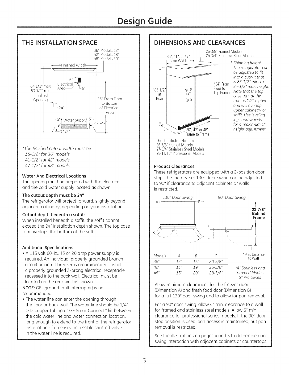
THE INSTALLATION SPACE
36" Models 12"
42" Models 18"
48" Models 20"
_inished Widt_
1
84 Z!2" max
85 q!2" min
Finished
Opening
*The finished cutout width must be:
35-!/2" for 36" models
4!-!/2" for 42" models
47-!/2" for 48" models
Water And Electrical Locations
The opening must be prepared with the electrical
and the cold water supply located as shown.
The cutout depth must be 24"
The refrigerator will project forward, slightly beyond
adjacent cabinetry, depending on your installation.
Cutout depth beneath a soffit:
When installed beneath a soffit, the soffit cannot
exceed the 2/4" installation depth shown. The top case
trim overlaps the bottom of the soffit.
, ElreeCtric°1_5,,
24"
Ii 5"_Water Supply_5'_
1
75" From Floor
to Bottom
of Electrical
IArea
1/2'
DIMENSIONS AND CLEARANCES
25-3/8"FramedModels
35",41" or47" 25-3/4"StainlessSteel Models
I_CaseVVidth.......... ......... I * Shipping height.
The refrigerator con
be adjusted to fit
into o cutout that
"84"From is 83-2/2" min. to
"83-1/
at
Rea
Frameto Frame
DepthIncludingHandles:
26-7/8"FramedModels
27-3/4"StainlessSteelModels
28-11/16"ProfessionalModels
Product Clearances
These refrigerators are equipped with a 2-position door
stop. The factory-set 130° door swing can be adjusted
to 90° if clearance to adjacent cabinets or walls
is restricted.
230°Door Swing 90° Door Swing
%J
Floorto 84-2/2" max. height.
TopFrame Note that the top
case trim at the
front is 2/2" higher
and will overlap
upper cabinetry or
soffit. Useleveling
legs and wheels
for o maximum 2"
height adjustment.42"or48"
23-7/8"
Behind
Frame
C
Additional Specifications
, A !!5 volt 60Hz., !5 or 20 amp power supply is
required. An individual properly grounded branch
circuit or circuit breaker is recommended. Install
a properly grounded 3-prong electrical receptacle
recessed into the back wall. Electrical must be
located on the rear wall as shown.
NOTE: GFI (ground fault interrupter)is not
recommended.
, The water line can enter the opening through
the floor or back wall. The water line should be 1/4"
O.D. copper tubing or GE SmartConnect _ kit between
the cold water line and water connection location,
long enough to extend to the front of the refrigerator.
Installation of an easily accessible shut-off valve
in the water line is required.
Models A B C *Min. Distance
36" 13" 15" 20-5/8"
42" 13" 19" 26-5/8" "4" Stainless and
48" 15" 20" 28-5/8" Trimmed Models.
toWall
5" Pro Series
Allow minimum clearances for the freezer door
(Dimension A)and fresh food door (Dimension B)
for a full 130° door swing and to allow for pan removal.
For a 90° door swing, allow 4" min. clearance to a wall,
for framed and stainless steel models. Allow S"min.
clearance for professional series models. If the 90° door
stop position is used, pan access is maintained, but pan
removal is restricted.
Seethe illustrations on pages 4 and S to determine door
swing interaction with adjacent cabinets or countertops.
Page 4
Refrigerator
Design Guide
23-7/8"From
Rearof
Refrigerator
Case
Trim 3/4"
_J 1/2" i
1/4" '
, I
u
u
u
u
u
u
u
u
u
u
u
u
u
m
m
m
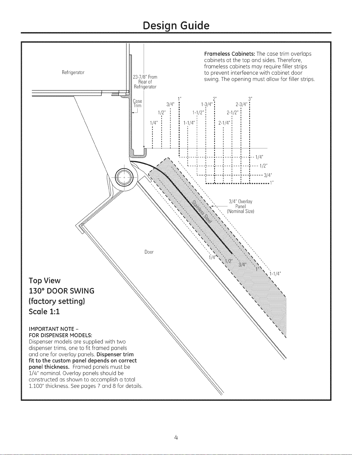
Frameless Cabinets: The case trim overlaps
cabinets at the top and sides. Therefore,
frameless cabinets may require filler strips
to prevent interfeence with cabinet door
swing. The opening must allow for filler strips.
Top View
130° DOOR SWING
(factory setting)
Scale 1:1
IMPORTANT NOTE-
FOR DISPENSERMODELS:
Dispenser models are supplied with two
dispenser trims, one to fit framed panels
and one for overlay panels. Dispenser trim
fit to the custom panel depends on correct
panel thickness. Framed panels must be
1/4" nominal. Overlay panels should be
constructed as shown to accomplish a total
1.100" thickness. See pages 7 and 8 for details.
Door
3/4" Overlay
Panel
(NominalSize)
i-1/4"
Page 5
Refrigerator
Design Guide
_Case Dim
i u
' ' 1/4"
i u
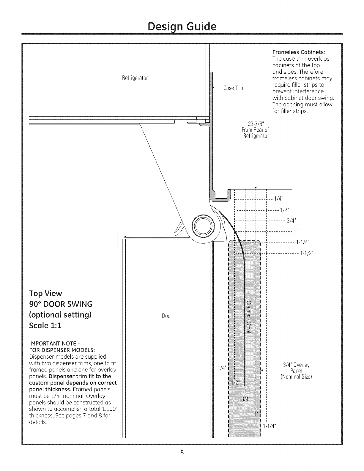
Frameless Cabinets:
The case trim overlaps
cabinets at the top
and sides.Therefore,
fromeless cabinets mGy
require filler strips to
prevent interference
with cabinet door swing.
The opening must allow
for filler strips.
23-7/8"
FromRearof
Refricerator
i
Top View
90 ° DOOR SWING
(optional setting}
Scale :1.::1.
IMPORTANT NOTE-
FOR DISPENSERMODELS:
Dispenser models (]re supplied
with two dispenser trims, one to fit
framed panels and one for overlay
panels. Dispenser trim fit to the
custom panel depends on correct
panel thickness. Framed panels
must be 1/4" nominal. Overlay
panels should be constructed as
shown to accomplish a total !.100"
thickness. See pages 7 and 8 for
details.
Door
Page 6
Design Guide
CUSTOMIZATION BASICS:
Framed Or Overlay Panels, Custom Handles and Accessory Kits
Professional Style Stainless Steel Refrigerators
Stainless steel wrapped refrigerators have beveled edges
and professional-style handles. These models are shipped
ready for installation.
Stainless Steel Wrapped Refrigerators
Stainless Steel wrapped refrigerators have wrapped doors
and grille panel, beveled edges, and tubular stainless steel
handles that coordinate with other Monogram appliances.
These models are shipped ready for installation.
Trimmed Refrigerators
Trimmed refrigerators are designed to be customized
with decorative panels. Field installed custom door
and grille panels are required.
Framed panels
You may install !/4" thick custom panels from
your cabinet manufacturer. The decorative panel slides
into the factory installed trim. Order black or stainless steel
accessory panels from your Monogram dealer.
I
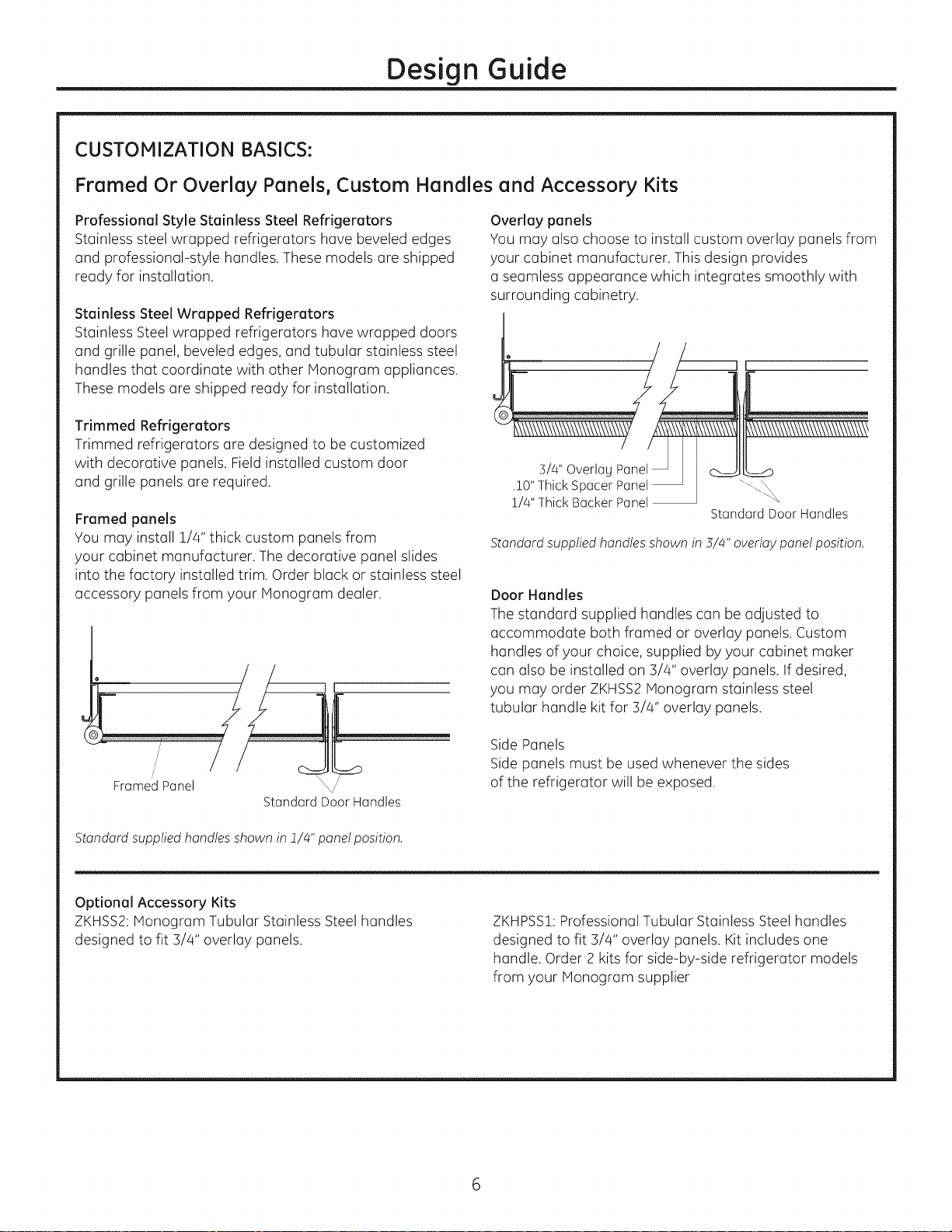
Overlay panels
You may also choose to install custom overlay panels from
your cabinet manufacturer. This design provides
u seamless appearance which integrates smoothly with
surrounding cabinetry.
5/4,, Overlag Panel H _ _\\\\\\\\\\\\\\\\\\\\
.!!/t[Thhii_kkSBPa_;rr Pp:_;I
StandardDoor Handles
Standard supplied handles shown in 3//4" overlay panel position.
Door Handles
The standard supplied handles can be adjusted to
accommodate both framed or overlay panels. Custom
handles of your choice, supplied by your cabinet maker
can also be installed on 3/4" overlay panels. If desired,
you may order ZKHSS2Monogram stainless steel
tubular handle kit for 3/4" overlay panels.
Framed Panel
StandardDoor Handles
Standard supplied handles shown in1//4" panel position.
Optional Accessory Kits
ZKHSS2:Monogram Tubular Stainless Steel handles
designed to fit 3/4" overlay panels.
Side Panels
Side panels must be used whenever the sides
of the refrigerator will be exposed.
ZKHPSSI: Professional Tubular Stainless Steel handles
designed to fit 3/4" overlay panels. Kit includes one
handle. Order 2 kits for side-by-side refrigerator models
from your Monogram supplier
Page 7
Design Guide
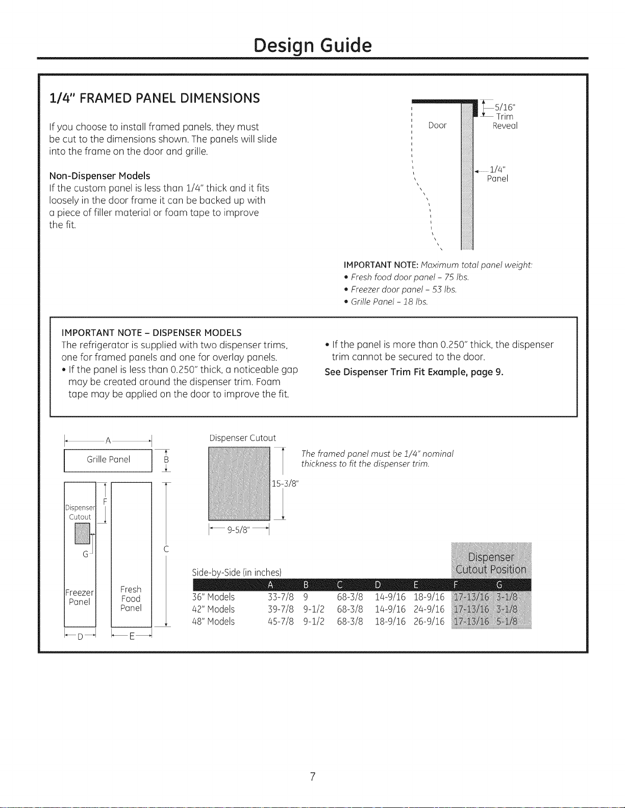
1/4" FRAMED PANEL DIMENSIONS
If you choose to install framed panels, they must
be cut to the dimensions shown. The panels will slide
into the frame on the door and grille.
Non-Dispenser Models
If the custom panel is less than 1/4" thick and it fits
loosely in the door frame it can be becked up with
a piece of filler material or foam tape to improve
the fit.
IMPORTANT NOTE- DISPENSERMODELS
The refrigerator is supplied with two dispenser trims,
one for framed panels and one for overlay panels.
. If the panel is less than 0.250" thick, a noticeable gap
may be created around the dispenser trim. Foam
tape may be applied on the door to improve the fit.
"'!75!!6"
Door
IMPORTANT NOTE:Maximum total panel weight:
• Fresh food door panel - 75 Ibs.
• Freezer door panel - 53 Ibs.
• Grille Panel - ]_8Ibs.
. If the panel is more than 0.280" thick, the dispenser
trim cannot be secured to the door.
See Dispenser Trim Fit Example, page 9.
Reveal
Panel
..............114"
Grille Panel
U
F
Cutout
Dispenser
Freezer Fresh
Panel Food
I-_D _1 I_E_
Panel
Dispenser Cutout
The framed panel must be if/z#" nominal
thickness to fit the dispenser trim.
15-3/8"
Side-by-Side(ininches)
36"Models 33-7/8 9 68-3/8 14-9/16 18-9/16
42"Models 39-7/8 9-1/2 68-3/8 14-9/16 24-9/16
48"Models /45-7/8 9-1/2 68-3/8 18-9/16 26-9/16
Page 8
Design Guide
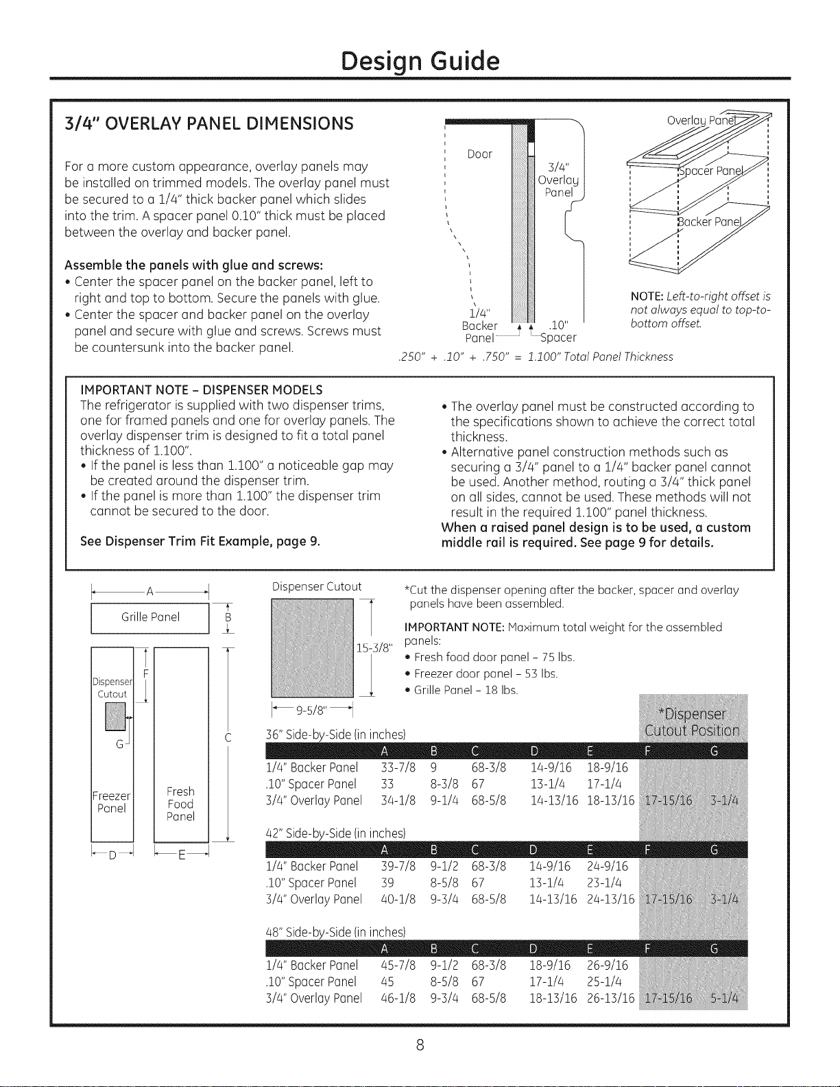
314'° OVERLAY PANEL DIMENSIONS
For a more custom appearance, overlay panels may
be installed on trimmed models. The overlay panel must
be secured to a 1/4" thick backer panel which slides
into the trim. A spacer panel 0.10" thick must beplaced
between the overlay and backer panel.
Assemble the panels with glue and screws:
, Center the spacer panel on the backer panel, left to
right and top to bottom. Secure the panels with glue.
, Center the spacer and backer panel on the overlay
panel and secure with glue and screws. Screws must
be countersunk into the backer panel.
IMPORTANT NOTE- DISPENSERMODELS
The refrigerator is supplied with two dispenser trims,
one for framed panels and one for overlay panels. The
overlay dispenser trim is designed to fit a total panel
thickness of 1.100".
, If the panel is less than 1.100" a noticeable gap may
be created around the dispenser trim.
, If the panel is more than 1.100" the dispenser trim
cannot be secured to the door.
See Dispenser Trim Fit Example, page 9.
_l\\x Xx\
i
bacKer 4 * .10"
NOTE:Left-to-right offset is
not always equal to top-to-
bottom offset.
Panel.......................Spacer
.250" + .lO" + .750" = l.lO0" Total Panel Thickness
, The overlay panel must be constructed according to
the specifications shown to achieve the correct total
thickness.
, Alternative panel construction methods such as
securing a 3/4" panel to a 1/4" backer panel cannot
be used. Another method, routing a 3/4" thick panel
on all sides, cannot be used. These methods will not
result in the required !.!00" panel thickness.
When a raised panel design is to be used, a custom
middle rail is required. See page 9 for details.
OverlaL
SackerPanel
A
GrillePanel B
F
Cutout
Dispenser L
Freezer Fresh
Panel Food
-- I
Panel
_D _ I_E_
Dispenser Cutout
15-3/8"
9-5!8" _
36" Side-by-Side (in inches)
1/4" Backer Panel 33-7/8 9 68-3/8 14-9/16 18-9/16
.10" Spacer Panel 33 8-3/8 67 13-1//4 17-1//4
3/4" Overlay Panel 3/4-1/8 9-1//4 68-5/8 1/4-13/16 18-13/16
*Cut the dispenser opening after the backer, spacer and overlay
panels have been assembled.
IMPORTANT NOTE:IVlaximum total weight for the assembled
panels:
, Fresh food door panel - 75 Ibs.
, Freezer door panel - 53 Ibs.
, Grille Panel - 18 Ibs.
42"Side-by-Side(ininches)
!/4" BackerPanel 39-7/8 9-!/2 68-3/8 !4-9/!6 24-9/!6
.10"SpacerPanel 39 8-5/8 67 13-1/4 23-1/4
3/4" OverlayPanel /40-1/8 9-3//4 68-5/8 1/4-13/16 2/4-13/16
48"Side-by-Side(ininches)
!/4" BackerPanel /45-7/8 9-!/2 68-3/8 !8-9/!6 26-9/!6
.10"SpacerPanel /45 8-5/8 67 17-1/4 25-1/4
3/4" OverlayPanel /46-1/8 9-3//4 68-5/8 18-13/16 26-13/16
Page 9

DISPENSER MODELS:
RAISED OVERLAY PANEL DESIGN
When a raised panel design isto be used,
a custom wide middle rail is required to accept
the dispenser trim.
. The middle rail must be wide enough to allow
for the dispenser trim to overlap the opening.
. The middle rail must be 1.100" total thickness
to accept the dispenser trim.
Design Guide
16-3/4"
1!4" Backer Panned
.10"Spacer
3/4" OverlayPan_
Wide
Middle
Rail is
Required
DISPENSER TRIM FIT EXAMPLES:
(NOT TO SCALE)
114" FRAMED PANEL
, The dispenser trim fits over the custom
panel and snaps into the freezer door.
, The clips will not engage the door
if the panel is more than 0.250" thick.
, If the panel is less than 0.250" thick,
a noticeable gap may be created
around the dispenser trim.
314" OVERLAY PANEL
, The dispenser trim fits over the custom
panel and snaps into the freezer door.
, The clips will not engage the door
if the panel is more than !.100" thick.
, If the panel is less than !.100" thick,
a noticeable gap may be created
around the dispenser trim.
10-5/8:1_1
1/4" FREEZERDOOR
Framed Thick
114" Dispenser Trim
114" Backer Panel
.I 0" Spacer
FREEZERDOOR
Total Thickness
0.250"
1.100"
3/4" Overlay Dispenser Trim
Page 10

Design Guide
SIDE PANELS
Side panels must be used
whenever the sides of the
refrigerator will be exposed.
The 1/4" side panels will
slip into the side case trim.
Secure the panels to the
refrigerator with stick-on
hook and loop fastener
strips. Order the side
panels from the cabinet
manufacturer.
, Cut a notch in the top
front corner as shown
to allow clearance for
corner keys in the front
side trim.
_84"
]_3" tO4"
2-9/16"
* Depending on instollotion height.
TOOLS AND MATERIALS REQUIRED
, Tinsnips to cut banding
, Stepladder
,1" Bit extension
, Tape measure
, Gloves
,1/4" Drywall screws
,5-Gal. Bucket with cover
,6" Spirit level
, Appliance hand truck
, Tubing cutter
,7/16" open-end wrench
, #2 Phillips screwdriver
, Drill and appropriate bits
,5/16", 7/16" socket
, Safety glasses
,1-1/8" open end wrench
, Pliers
,1/4", 5/16" Combo Rachet
,35" long 2x4 for Anti-Tip support
,1/4" copper water linetubing or GE SmartConnect _
Refrigerator Tubing kits
, Water shut-off valve
, Custom panels for doors and grille panel
, Screws to secure refrigerator to cabinetry
, Stick-on hook and loop fastener strips for
1/4" side panels
HARDWARE SUPPLIED
, Water filter bypass plug
, Anti-Tip brackets
,1/4" nut and ferrule
, Dispenser trims for 1/4" and 3/4" overlay panels
(for use with Custom Panel models).
, Aluminum cover trim for 3/4" overlay panels
with custom handles. Includes 22flat head screws
and 4 endcaps.
FLOORING
Forproper installation, this refrigerator must be placed
on a level surface of hard material that is at the same
height as the rest of the flooring. Thissurface should
be strong enough to support a fully loaded refrigerator,
or approximately 1,500 Ibs.
NOTE:Protect the finish of the flooring. Cut a large
section of the cardboard carton and place under
the refrigerator where you are working.
GROUNDING THE REFRIGERATOR
IMPORTANT - (Pleese reed cerefully}
FOR PERSONAL SAFETY,THIS APPLIANCE MUST
BE PROPERLY GROUNDED.
The power cord of this appliance is equipped
with a 3-prong (grounding) plug which mutes
with a standard :3-prong (grounding) wall receptacle
to minimize the possibility of electric shock hazard
from this appliance.
Have the wall outlet and circuit checked by
a qualified electrician to make sure the outlet
is properly grounded.
Where a standard 2-prong wall outlet is encountered,
it isyour personal responsibility and obligation
to have it replaced with a properly grounded
:3-prong wall outlet.
DO NOT, UNDER
ANY CIRCUMSTANCES,
CUT OR REMOVE
THE THIRD (GROUND) PRONG
FROM THE POWER CORD.
DO NOT USE AN ADAPTER PLUG TO CONNECT
THE REFRIGERATOR TO A 2-PRONG OUTLET.
DO NOT USE AN EXTENSION CORD WITH THIS
APPLIANCE.
10
Page 11

Installation Instructions
ISTEP 11 REMOVE PACKAGING
CAUTION: The refrigerator is much heavier at
thetopthanatthebottom-be carefulwhen moving.
When using a hand truck, handle from the side only.
PRUDENCE: Ler6frig@ateur est beaucoup
plus Iourd en haut qu'en bas. IIfaut @treprudent Iors
des d@lacements. Si un diable est utilis6, il faut soulever
le r6frig6rateur sur le c6t6 seulement.
, Carefully cut banding at the top and bottom,
remove the outer carton.
, Slide out the back corner posts (2).
Slide the carton off the top of the cabinet.
NOTE:IT ISNOTNECESSARYTO LAYTHECABINETDOWN
IN ORDERTO REMOVETHE SKID!
The unit is secured to the skid with 4 slotted
tie-down straps. Remove the six 7/16" bolts
from the base channels in the tie-downs.
[STEP2 MOVE THE REFRIGERATOR INTO THE HOUSE
The support blocks on the bottom of the refrigeration
case must be removed before the refrigerator is
taken off the skid or damage will occur. Carefully
tilt the refrigerator and slide the blocks out from
beneath.
Q
Remove the toekick and set aside for final installation.
Q
Lift the refrigerator off the skidwith an appliance
dolly. Handle from the sides.
, Remove the six 7/16"
bolts securing the straps
to the skid.
CAUTION" DoNOT
ATTEMPTTO ROLLUNIT
OFFSKID.
Remow
miepaw,PRUDENCE: ,LNE
FAUTPASESSAYERDE FAIRE
_¢ ROULERLEREFRIGERATEUR
POURL'ENLEVERDELAY
PALETTE.
, Re-use the corner posts from the packaging to protect stainless steel models. Runthe appliance dolly straps over
the posts and under the handles.
, Leave the protective film on the refrigerator until installation is complete.
IMPORTANT:Never lift the refrigerator by the handle or push against the grill panel; this could cause damage
or misalignment.
, Avoid laying the unit on its back or side to prevent sealed system restrictions.
ISTEP 3J INSTALL WATER LINE
, A cold water supply is required for automatic
icemaker operation. The water pressure must
be between 40 and 120 p.s.i.
, Route 1/4" ODcopper or GESmartConnect "
plastic tubing between house cold water line
and the water connection location.
, The tubing should be long enough to extend
to the front of the refrigerator. Allow enough tubing
to accommodate the bend leading into the water line
connection.
NOTE:The only GEapproved plastic tubing issupplied
in the GESmartConnect T"Refrigerator Tubing kits.
Do not use any other plastic water supply line because
the line is under pressure at all times. Other types
of plastic may crack or rupture with age and cause
water damage to your home.
GESmartConnect " Refrigerator Tubing Kits are
available in the following lengths:
2' (.6 m) WXO8XIO002
6' (1.8 m) WXO8XIO006
15' (4.6m) WXO8X10015
25' (7.6m) WXO8X10025
_Cold WaterLine
11
Page 12

Installation Instructions
ISTEP 31 {continued)
Shut off the main water supply.
Turn on the nearest faucet long enough to clear the line
of water.
, Install a shut-off valve between the icemaker water
valve and cold water pipe in a basement or cabinet.
The shut-off valve should be located where it will be
easily accessible.
, Turn on the main water supply and flush debris.
Run about a quart of water through the tubing into a
bucket. Shut off the water supply at the shut-off valve.
NOTE: Saddle type shut-off valves are included in many
water supply kits. Before purchasing, make sure a saddle
type valve complies with your local plumbing codes.
NOTE: Commonwealth of Massachusetts Plumbing
Codes 248CMR shall be adhered to. Saddle valves
are illegal and use is not permitted in Massachusetts.
Consult with your licensed plumber.
[STEP 4 1INSTALLATION WITH
HOUSEHOLD WATER
FILTRATION SYSTEM
Skip this step if you do not have a household water
filtration system
If the water supply to the refrigerator is from
any household water filtration system, the filter
cartridge should be removed. For better ice and water
performance, remove the filter and install the filter bypass
plug.
ISTEP 6 1INSTALL ANTI-TIP BRACKETS
WARNING: .TI-TIPPRECAUTIO.S
The refrigerator istop-heavy and must be secured
to prevent the possibility of tipping forward.
ATTENTION: PRECAUTIO.SCO.TRE
LESBASCULEMENTS
Le r6frig6rateur est beaucoup plus Iourd en haut
et il faut le maintenir en place pour 6viter la possibilit6
de son basculement vers I'avant.
. Cut a 2" x 4" block, 35" long and secure the block
to the mounting brackets provided using #12 or #14
wood screws.
2x4Cut
35" Length ,_ ,_
Installation Mounting-
Height Bracket
From Floor
Screws Mounted into _
Vertical Wall Studs
. Secure the bracket with wood block to the back wall
so that it is 84" (or your installation height) from
the finished floor. Use #12 or #14 wood screws.
See the illustration.
Brackets I
Required
,i ,'!
Brackets
Not Required
Beneath a
Soffit
RotateCounterclockwiseTo FilterBypass
Remove Plug
[STEP 5 INSTALL SIDE PANELS
Skipthis step when not using side panels.
If you are using !/4" side panels, they should
be inserted into the case trim. Fasten the panels
to the refrigerator with stick-on hook and loop
fastener strips before setting the refrigerator in place.
Side View
. The screws must penetrate at least one inch
into the vertical wall studs.
Connect power cord:
. Before pushing the refrigerator into the opening, plug
the power cord into the receptacle. Open the grille
panel and reach into the opening at the back to grasp
the power cord. Pull the power cord into the opening
as you push the refrigerator back.
. Gently push refrigerator into the opening with hands
against front corners.
IMPORTANT NOTE: When the refrigerator is installed under a soffit
or if there is not enough height for this method of security, brackets
cannot be used. Proceed to step 7 to level the refrigeretor and then to
step 9 to secure refrigerator to cebinets. See step 8 if you have metal
wall studs. The refrigerator must be secured to prevent tipping.
12
Page 13

Installation Instructions
JSTEP 71 LEVEL REFRIGERATOR
All models have 4-point leveling. The front is
supported by leveling legs, the rear is supported
by adjustable wheels. Both are accessible from
the front of the refrigerator.
, To level the back of the refrigerator, turn the 7/16"
hex nut located above the front wheels. Turn
clockwise to raise or counterclockwise to lower the
refrigerator.
Forfront leveling, use a 1-!/4" open-end wrench.
Adjust height of refrigerator to match installation
cutout opening 83-1/2" to 84-1/2". The refrigerator
should be level and plumb with cabinetry.
Hex Nut Ad
Rear Wheels
JSTEP 8 ALTERNATE ANTI-TIP
PROCEDURE
The refrigerator must be secured to prevent tipping.
The anti-tip brackets cannot be used on metal
well studs. Use this Alternate Procedure to secure
the refrigerator against tip-over whenever metal
wall studs are encountered and there is no soffit.
i'
_SIde View /
Top Case Trim _T@pCaseTjri_
/ /--\
_-I/2" DrywallScrews
Through Trimand Into Soffit
or 3/4" Min.Wood grace
CAUTION:
The rear leveling wheels and front leveling legs
are limited to a maximum height adjustment of 1".
If the installation requires more than 84-1/2" height,
the installer should elevate the refrigerator on a sheet
of plywood or runners. Cabinetry trim could also
be added across the top of the opening to shorten
the opening. If you attempt to raise the refrigerator
more then 1", you will damage the front leveling
legs end the rear leveling wheels. Make adjustments
in smell increments.
PRUDENCE
Les roues de nivellement arri_re etles pattes de
nivellement avant permettent un r6glage maximal
de 25 mm (1 po).Si I'ouverture pour le r6frig6rateur
a une hauteur sup6rieure 6 2,15 m (84-1/2 po),
I'instollateur doit 61everle r6frig6rateur sur une feuille
de contre-plaqu6 ou des glissi_res. IIest 6galement
possible d'ajouter des baguettes de finition des
placards sur le haut de I'ouverture afin de la r6duire.
Lever le r6frig6rateur de plus de 25 mm 11po}
endommege les pattes de nivellement avant
et les roues de nivellement arri_re.
. Raisethe grille panel to access case trim.
. Use a 3/!6" bit to drill four evenly spaced clearance
holes through the metal top case trim.
Use a 1/16" bit to drill to pilot holes through the metal
clearance holes and into the wood soffit. The holes
should be centered in the soffit or a 3/4" min. wood
brace. The brace spanning the enclosure must
be securely fastened to cabinets on both sides.
Install four, 1-1/2" drywall screws into the pilot holes.
13
Page 14

Installation Instructions
ISTEP 9] SECURE REFRIGERATOR
TO CABINETRY
Whenever possible, perform this step for anti-tip
security, or when anti-tip brackets cannot be used.
The refrigerator must be secured to prevent tipping.
, Raisethe grille panel to access the case trim.
Drill a hole in the trim and drive a screw through
the trim into the adjacent cabinet
Follow the same procedure on the opposite side.
Through Case Trim Into
Adjacent Cabinets
ISTEP iOJ ADJUST DOOR SWING
ISTEP 111 INSTALL GRILLE PANEL
(forCustom PonelModels only)
To insert the framed or overlay panel into the grille:
, Roisethe grille ponel to the stop position.
A:== j
Loosen Loosen
Side Side
Trim Trim
Screw Screw
Adjust Nut Below
Spring to Accommodate
PanelWeight
Loosen the screws on the side trim behind the frame.
Remove the bottom trim.
NOTE:This refrigerator has a 2-position door stop.
When space does not allow the door to swing open
fully to !30 °,you may change the door swing to a 90°
opening. Skip this step if door opening is satisfactory
for your installation situation.
130°
Interior
Door
/
/'
Hinge
Open the door to view the bottom hinge.
Note the door stop pin locations. The pin is factory
installed in the !30 ° position.
Close the door. From below, use pliers to unscrew
the door stop and reinstall into the 90° position.
CAUTION: The metal panel may be
slippery. Grip the metal panel firmly so the panel does
not slip out of the frame and cause personal injury or
damage to the frame.
PRU DENCE : Lepanneauenm6tal
peut b_tre glissant. Tenir fermement le panneau en
m#tal, de mani_re (_ce que le panneau ne glisse pas
en dehors du cadre en provoquant des blessures
corporelles ou des dommages au cadre.
, Slide the panel over the metal backer panel and into
the trim.
, If necessary, tap with a wood block until the panel
slips under the top trim piece.
, Reassemble the bottom trim. Tighten the screws.
Adjust the hinge spring to accommodate the panel
weight, if necessary.
14
Page 15

Installation Instructions
ISTEP 12J INSTALL 1/4" FRAMED PANELS
!]_!]_!]_!]_!]_!]_!]_!]_!]_!]_!]_!]_!]_!]_!]_!]_!]_!]_!]_!]_!]_!]_!]_!]_!]_!]_!]_!]_!]_!]_!]_!]_!]_!]_!]_!]_!]_!]_!]_!]_!]_!]_!]_!]_i!_
!]!]!]!]!]!]!]!]!]!]!]!]!]!]!]!]!]!]!]!]!]!]!]!]!]!]!]!]!]!]!]!]!]!]!]!]!]!]!]!]!]!]!]!]i!
!]!]!]!]!]!]!]!]!]!]!]!]!]!]!]!]!]!]!]!]!]!]!]!]!]!]!]!]!]!]!]!]!]!]!]!]!]!]!]!]!]!]!]!]i!
!]!]!]!]!]!]!]!]!]!]!]!]!]!]!]!]!]!]!]!]!]!]!]!]!]!]!]!]!]!]!]!]!]!]!]!]!]!]!]!]!]!]!]!]i!
¢_ • • 90
i
Install door panels:
. Open the door to 90°. Remove the 6 Phillips head screws
from the door handle.
. Remove the handle. Retain all screws.
. Remove the 6 screws holding the trim, then lift off
the trim. Retainthe screws.
. Slide the framed panel into the door trim.
Go to Step I2A for Overlay Panels
Handle
Trim
k\\\\\\\\\\\\\\\\\\\\\/
Supplied
Handle Shown
in 2//4" Panel
Position
Door Trim
Refrigerator
Door
Dispenser Models Only:
. The dispenser controls protrude beyond the face
of the freezer door. To avoid damage to the dispenser,
the trim at the top of the door should be removed.
. Remove the screws holding the top trim in place.
. Place the freezer panel into the bottom channel
and slide into the hinge side trim.
. Reinstall the top trim piece with screws.
. There are two sets of holes in the handle side trim.
Replace the handle side trim by installing the original
screws inthe FRONTscrew holes.
. Secure the handle to the door using the REARscrew
holes.
. Follow the same procedures to install the opposite panel.
. Check to besure the handles are evenly aligned with
each other at the top. To adjust, loosen the handle
screws and slide up or down. Tighten the screws.
NOTE:Aluminum cover trim is supplied for use with
custom handles on overlay panels. It is not intended for
use with 1/4" panels. Discard the cover trim when using
1/4" framed panels.
\
'\\\
/ Use Front Hole
to Secure Trim
\ Use Rear Holes
to Secure Handle
15
Page 16

Installation Instructions
ISTEP 12A IINSTALL OVERLAY PANELS
Install door panels:
. Open door to 90°. Remove the 6 Phillips head screws
from the door handle.
. Remove the handle. Retain all screws.
. Remove the 6 screws holding the trim, then lift off
the trim. Retainthe screws.
. Slide the overlay panel into the door trim.
Handle
Trim
Forward
For 3/4"
Move
Panel
l
Door Trim
Refrigerator
Door
Supplied Hond/e
Shown in Over/oy
Pone/Position
Dispenser Models Only:
. The dispenser controls protrude beyond the face
of the freezer door. To avoid damage to the dispenser,
the trim at the top of the door should be removed.
. Remove the screws holding the top trim in place.
. Place the assembled freezer panel into the bottom
channel and slide into the hinge side trim.
. Reinstall the top trim piece with the screws.
. There are two sets of holes in the handle side trim.
Replace handle side trim by installing the original screws
in the REARscrew holes.
. Secure the handle to the door using the FRONT
screw holes.
. Follow the same procedures to install the opposite panel.
. Check to besure the handles are evenly aligned with
each other at the top. To adjust, loosen the handle
screws and slide up or down. Tighten the screws.
//
/
", ?" Use Front Hole'.
'_ _ tO Secure Handl,
- -.......... use uear HOleS
to Secure Trim
16
Page 17

Installation Instructions
ISTEP 12AI {continued)
Custom Handles
. If you are using custom handles, the handle must
be properly secured to the overlay panel before sliding
the panel into the trim.
. The cabinet manufacturer will supply the custom
handle and hardware.
. Discard the supplied handle.
Reinstallalloriginalscrews.
. Reinstall the handle side trim, using all 12 supplied
flat-head screws, plus the 12flat-head screws
originally installed in the handle trim.
. Install a supplied end cap onto the top of the door,
using a Phillips head screwdriver and the 2 screws
provided. Hand-tighten the screws into the end caps.
Do not overtighten; damage will occur.
. Clean the aluminum trim with rubbing alcohol-
do not use alcohols with oil or lanolin that will prevent
adhesion of double-sided tape.
. Slip the aluminum cover trim behind the top end cap
to check the fit. The aluminum cover trim has a recess
on each end which fits the end cap.
ISTEP 12AI {continued)
. Carefully place the aluminum cover trim into top
end cap so that the recess isaligned with the cap.
Use the top to bottom grooves along the handle side
to align the cover trim accurately. Pull the tape a few
inches at a time while pressing the trim against
the door. Press and hold approximately 10 seconds
before continuing along the length of the door.
. Install another end cap at the bottom of the door
to secure the cover trim. Use a stubby Phillips head
screwdriver and the 2screws provided.
NOTE:Make sure there are no gaps in the installation.
. Follow the same procedure on the opposite door.
Cover Trim
Insert Aluminum
TrimInto End
Cop.
U
. Remove the trim. Peelaway a few inches
of the adhesive backing.
IMPORTANT:The tape isvery sticky and strong. Once
it adheres to a surface, it cannot be removed without
damaging both surfaces. Do not install the trim before
the final wood panels are in place. Besure to align
the trim carefully before removing the paper backing.
Top End Cap
Fits Over the
Aluminum Trim.
Secure Cop with
2 Screws.
17
Page 18

Installation Instructions
STEP 131 INSTALL DISPENSER TRIM
Skipthis step is you are installing a stainless steel
wrapped or a non-dispenser refrigerator.
There are two dispenser trims shipped with your
refrigerator. Select the appropriate trim for your
application.
J
Framed
Panel
Trim
Compare the dispenser trims. Note that
the inside depth of the frames are different.
Choose the trim with lessdepth for framed
panels, choose the deeper one for overlay
panels.
Dispenser trim fit over the custom panel depends on
correct panel thickness. See pages 7 and 8 for panel
construction information.
J
Overlag
Panel
Trim
[STEP 14 CONNECT WATER SUPPLY
L
.......,, Refrigerator House /'
_Water Supplg Water Supp!_gf
,, Locate and bring the tubing to the front
of the cabinet.
, Turn the water on to flush debris from the line.
Run about a quart of water through the tubing
into a bucket, then shut off the water.
Copper Tubing:
, Slip a 1/4" nut and ferrule (provided) over both ends of
the copper tubing. Insert the tube into the union fitting
on the unit and tighten the nut to the union.
, Turn on the water to check for leaks.
, Pressand snap the dispenser trim into the dispenser
recess on the refrigerator door.
If an excessive gap exists around the dispenser trim
or if the panel fits loosely in the door frame, foam tape
may be applied to help improve the fit. Remove
the trim and panel and apply the foam tape
to the door around the dispenser and in the corners.
GESmartConnect _"Tubing:
, Insert the molded end of the tubing
into the refrigerator connection. Tighten
the compression nut until it isjust hand tight.
, Tighten one additional turn with awrench.
Overtightening can cause leaks!
, Turn on the water to check for leaks.
NOTE:Make sure excess tubing length does not
interfere with the toekick installation.
18
Page 19

Installation Instructions
ISTEP 151 CONNECT POWER, CLOSE
GRILLE PANEL
, Open the grill panel.
, Plug in the power cord (if necessary) by reaching
into the opening next to the water filter. Ifaccess is
too tight, remove the 2 screws holding the water filter
bracket and move aside. Plug in the power cord and
secure the bracket with the original screws.
\
Maste'iLight
Switches
, Check to make sure power to refrigerator is on
by opening refrigerator door to see if interior lights
are on.
, The temperature controls are preset at 37°F for
the fresh food section and 0°F for the freezer.
, Allow 24 hours to stabilize before making
adjustments.
ISTEP 161 START ICEMAKER
Electrical
OutletAccess
ISTEP 171 INSTALL TOEKICKS
, Locate the supplied toekicks (shipped taped to
the side of the refrigerator).
, First, attach the LARGERtoekick to the refigeretor
using ONLYthe top center hole (1).
, Next, attach the toekick extension to the refrigerator
using the three lower slots (2).
F_F_0 o..(1/ 1__]
, A custom toekick can be installed to match or
complement the surrounding cabinetry. Usethe
supplied toekick as a template to cut the shape.
INSPECT FINAL INSTALLATION
Check door alignment
Stand back away from the refrigerator to inspect
the final installation.
, Check to be sure the handles are evenly aligned with
each other at the top. To adjust, loosen the handle
screws and slide up or down. Tighten the screws.
, Shipping or the addition of heavy door panels
may have caused the doors to move slightly out
of alignment.
lcemaker
/
Power
Switch
, Slide the switch to ON. The icemaker will begin
operation automatically.
, Be sure nothing interferes with the sweep
of the feeler arm.
, Discard the first full bucket of ice cubes.
, To turn the icemaker off, slide the switch to OFF.
Feeler Arm
Door Out of
Alignment
IIh_]
Bushing
/
z
/
\..Roise
, If necessary, the fresh food door may be adjusted up
or down to align with the freezer door.
, Use u 5/16" wrench to adjust the hinge pin us shown.
19
z
5/16"Wrencl\
_\\\\\\\
Page 20

ZKHSS2 Tubular Stainless Steel Handles
This kit provides for the installation of Tubular Stainless Steel
handles on 3/4" overlay custom panels.
TOOLS AND MATERIALS REQUIRED
In addition to the custom door panels, you need:
• #2 Phillipsscrewdriver • Centerpunch
• Drill and 7/32" bit
and 7/8" spade bit
• Safetyglasses
• Hammer
• Pencil
PARTS LIST
[STEP i] REMOVE DOOR HANDLES
. Open the refrigerator door to 90°. Remove
the 6 screws holding the handle to the door.
. Remove the 6 screws holding the handle side trim.
Retain all screws and trim. Discard the handle.
. Follow the same procedure to remove the freezer
handle and trim.
8 Handlestandoffs
10 Screws for handle
32x'/" pan head machine
screws (8 required, 2 extra)
10 Set screws (8 required, 2 extra)
3/32" Allen wrench for set screws
10 Plastic spacers standoffs #10-
(8required,2extra)
20
Page 21

ZKHSS2 Tubular Stainless Steel Handles
[STEP 2 INSTALL HANDLE ONTO PANELS
Drill Pilot Holes
, Heasure, mark and draw a line, 1-1/8" from
the handle side edge, top to bottom.
, Hold the tubular handle against the appearance side,
centered top to bottom and on the marked line.
, Mark the screw hole locations at the center
of the handle attachment posts. Place the handle
over the marks to check again that the holes are
aligned to the handle posts.
, Center punch to mark the hole locations. Drill 7/32"
pilot holes from the appearance side and through
the entire panel thickness.
, Follow the same procedure to drill pilot holes
on the opposite door.
uuuuuuuuuuuuuuuuuuuuuuuuuuuuu_
1-1/8"
uuuuuuuuuuuuuuuuuuuuuuuuuuuuuuuu
[STEP 2 ](continued)
Secure Handles to Panels
, Use a 7/8" spade bit to drill 1/2" to 9/16" max. depth
into the back side of the panel. At this depth there
will be enough screw threads to engage the handle
on the appearance side. Seethe illustration below.
, Stand the panel up on the hinge side. Place a plastic
spacer into the 7/8" opening, then drop the screw
through the spacer.
7/32"
, Place the handle standoffs against the mounting
screws on the appearance side, then drive the top
screw partially into the standoff.
, Drive the next screw partially into the standoff.
Continue installing screws to the bottom location.
Alternate back to the top tightening screws one
at a time until the handle is tight against the panel.
_i_!i!i!i!i!i!i!i!i!i!i!i!i!i!i!i!i!i!ii
CAUTION: Hole locations must 8e exact to
accept hand/e standoff and hand/e assembly.
Assemble Handles
. Place a handle standoff on each attachment post on
the handle. Position the screw hole on the standoff to
point to the floor.
, Install set screws into the bottom of each standoff,
using the Allen wrench provided. The standoff should
be tight against the handle.
\,
Attachment Post
screw into
panel as shown.
Countersink
21
Page 22

ZKHSS2 Tubular Stainless Steel Handles
[STEP 3 INSTALL ASSEMBLED HANDLES
. Slide the assembled panels into the door trim.
. Secure both trims using all the original screws.
Dispenser Models Only:
, The dispenser controls protrude beyond the face of
the freezer door. To avoid damage to the dispenser,
the trim at the top of the door should be removed.
. Remove the screws holding the top trim in place.
Lift off the trim.
. Place the freezer panel into the bottom channel
and slide into the hinge side trim.
. Reinstall the top trim piece with screws.
[STEP 4] INSTALL DISPENSER TRIM
For Dispenser Models Only:
There are two dispenser trims shipped with your
dispenser refrigerator. Note that the inside depth
of the frames are different. Choose the trim marked
3/4" overlay panels.
, Press and snap the dispenser trim into the dispenser
recess on the door.
IUlspense_
rh Trim
Reinstall all original screws
22
Page 23

Notes
23
Page 24

014
o9-13GE
Printed in the United Stotes
NOTE:While performing instollotions described in this book,
sofety glosses or goggles should be worn.
For Honogrom _ Iocol service in your oreo, coil
1.800.444.1845.
NOTE:Product improvement is o continuing endeovor ot
Generol Electric. Therefore, moteriols, oppeoronce ond
specificutions ore subject to chonge without notice.
GE Appliances & Lighting
Applionces
Gener(]l Electric Compony
Louisville, KY40225
GEApplionces.com
 Loading...