

GE ZIF360NXALH, ZIF360NXARH, ZIFP360NXALH, ZIFP360NXARH, ZIFS360NXALH Installation Guide
...Page 1

Installation
Instructions
36" Built-In All-Refrigerators
and All-Freezers
31-/461/48
22/402601PO01
06-08 JR
monogram.com
Page 2

Safet l Information
BEFORE YOU BEGIN
Read these instructions completely and carefully.
•IMPORTANT- Savetheseinstructions
forlocalinspector'suse.Observeallgoverning
codesand ordinances.
• Note to Installer - Be sure to leave these
instructions with the Consumer.
• Note to Consumer - Keepthese instructions
with your Owner's Manual for future reference.
AWARNING:
This appliance must be properly grounded.
See "Grounding the Unit," page 10.
AAVERTISSEMENT
Cet appareil doit @trecorrectement mis @laterre.
Consulter <<Mise@laterre de I'appareil m@nager >>,
page 10.
If you received a damaged product, you should
immediately contact your dealer or builder.
ACAUTION:
Due to the weight and size of this product, and to reduce
the risk of personal injury or damage to the product -
THREEPEOPLEAREREQUIREDFORPROPERINSTALLATION.
APRUDENCE
A cause du poids et de la taille de ce produit et
pour r@duirelerisque de blessure et de dommages,
IL FAUTTROISPERSONNESPOURFAIREL'INSTALLATION
CORRECTEMENT.
Skill Level -Installation of this product requires basic
mechanical, carpentry and plumbing skills. Proper
installation is the responsibility of the installer. Product
failure due to improper installation is not covered
under the GEAppliance Warranty. Seethe Owner's
Manualfor warranty information.
WARNING:
• These units are top-heavy and must be secured
to prevent the possibility of tipping forward. Anti-Tip
protection is required. See page 12 for details.
• Usethis appliance only for its intended purpose.
• Immediately repair or replace electric service cords
that become frayed or damaged.
• Unplug the unit before cleaning or making repairs.
• Repairsshould be made by a qualified service
technician.
AAVERTISSEMENT
• Ces appareils m@nagerssont Iourds en haut
et il faut les arrimer pour @viterleur basculement.
II faut avoir un syst@mede protection contre
le renversement. Voir les d@tailspage 12.
• IIne faut utiliser cet appareil que pour I'utilisation
appropri@e.
• R@parerou remplacer imm@diatement tout cordon
@lectriqueeffiloch@ou endommag@.
• IIfautd_brancherl'appareilm_nager avant
le nettoyage ou toute intervention.
• Lesr@parations doivent @trefaites par un technicien
qualifi&
For Monogram local service in gour area,
1.800.444.1845.
ForMonogram serviceinCanada
1.800.561.3344
ForMonogram Partsand Accessories,
call1.800.626.2002.
www.monogram.com
CONTENTS
Design Guide
TheInstallationSpace ......................................3
Dimensionsand Clearances......................3-4
130° Door Swing..................................................5
90°DoorSwing....................................................6
CustomizationBasics........................................7
PanelDimensions................................................8
SidePanels..............................................................9
ZUG2GrillePanelDimensions......................9
Installation Instructions
Tools, Hardware, Materials ..........................10
Grounding the Unit ..........................................10
Step 1,Remove Packaging ..........................11
Step 2, Install Water Line ............................11
Step 3, Install Side Panels ............................11
Step 4, Install Anti-Tip Bracket ..........12-14
Step 5, Level Unit ..............................................15
Step 6, Secure Unit to Wall ..........................16
Step 7, Adjust Door Swing ..........................17
Step 8, Install Grille Panel ............................17
Step 9, Install Framed Panels ....................18
Step 9A, Install Overlay Panels ................19
Step 10,Connect Water Supply ................20
Step 11, Start Icemaker ................................20
Step 12, Install Toekick ..................................20
Page 3

Design Guide
THE INSTALLATION SPACE
I_ FinishedWidth "t
Thefinished _ 2-5/16" Wall View
cutoutwidth
mustbe j _ 5:!!2:
35-1/2". j l_l_ Electrical
84-1/2"max
Water And Electrical Locations
Electrical and water supplg must be located as shown.
The Cutout Depth Must Be 24" Minimum
The unit will project forward, slightlg beyond adjacent
cabinetrg, depending on gour installation.
Cutout Depth Beneath a Soffit:
When installed beneathh a soffit, the soffit cannot
exceed the 24" installation depth shown. The top case
trim overlaps the bottom of the soffit.
Additional Specifications
• A 115volt 60Hz., 15 or 20 amp power supplg
is required. An individual properl9 grounded branch
circuit or circuit breaker is recommended. Install
a properl9 grounded ]-prong electrical receptacle
recessed into the back wall. Electrical must be
located on rear wall as shown.
Note: GFI(ground fault interrupter)is not
recommended.
• Water line can enter the opening through the
floor or back wall. The water line should be 1/4" O.D.
copper tubing or GEQuickConnect T"kit between the
cold water line and water connection location, long
enough to extend to the front of the unit. Installation
of an easilg accessible shut-off valve in the water line
is required.
35-1/2"
"1
] g" Area
24"Minimum i
Cutout Depth J
3-1/2" 3-1/2"
i
DIMENSIONS AND CLEARANCES
35"
CaseWidth
_°°} j.-vi
DepthIncludingHandles:
26-7/8" FramedModels
27-3/4" StainlessSteelModels
28-11/16" ProfessionalModels
Product Clearances
These units are equipped with a 2-position door stop.
The factorg set 1]0 ° door swing can be adjusted to 90°
if clearance to adjacent cabinets or walls is restricted.
Order WX14X99 door stop for precise settings between
90° and 1]0 °.
130° DoorSwin(
7
130°
Allow 25" minimum cleoronce for o full
1]0 ° door swing. Allow 15" for pon removal.
For o go° door swing, allow 4" minimum clearance
to o woll for fromed ond stoinless steel models.
Allow 5" minimum cleoronce for professionol models.
If the 90° doorstop position is used, pon occess
is mointoined but pon removol is restricted.
See illustrotions poges 5 ond 6 to determine door swing
interoction with odjocent cobinets or countertops.
25-3/8"FramedModels
25-3/4"StainlessSteelModels
CaseDepth * Shipping height. The
, product can be adjusted
"84"From max. height. Note that
Floorto the top case trim
TopFrame at the front is 1/2" higher
_. cabinetrg or soffit. Use
.........:: 36" Frameto
FrameWidth
25"--
Minimum
to Wall
to fit into a cutout that
is 83-1/2" min. to 84-1/2"
and will overlap upper
leveling legs and wheels
for a maximum 1" height
adjustment.
90° DoorSwing
90° DoorSwing
L
*4" stainlessandtrimmedmodels.
*Minimum
to aWall
i i
i
i
i l
'/
l i
i 136-3/4"
5" Promodels.
13_7/8,,
CaseBehind
F/ame
3
Page 4

CLEARANCES
Design Guide
4" Min. to Wall
130° Door
Swing
.....130° .........
Ii to
0 DoorSwing
z
36-3/4"
.L
These units are equipped with a 2-position door stop.
The factory set 1]0 ° door swing can be adjusted to 90°
if clearance to adjacent cabinets or walls is restricted.
Order WX14X99 door stop for precise settings between
90° and 1]0 °.
When Installed into a corner:
Allow 25" for a full 1]0 ° door swing. Allow 15" for pan
removal. Allow 4" min. clearance when door swing
is adjusted to a 90° opening for pan access but pan
removal is restricted.
1"
130° Door 130° Door
Swing Swing
II I',
_L k'X
/ _, "k'X
25"
Min.to
Wall
2"
Fr i
Clearances for two products installed side-bg-side
with the same (left or right) door swing
Allow 2" minimum clearance between the products
to prevent door swing interference. Order the WX14X99
adjustable door stop to reduce the factory set 1]0 °
door swing. Allow 15" minimum to a wall to achieve
full drawer extension and pan removal.
NOTE:ZUG2 and ZUGSS2Grille Panel Kit will NOT fit this
installation.
5"
! i
'.... ,,"1%,
........:<i'L:
Clearances for Multiple Single Door Installations
In a side-by-side installation of a left and right door
swing product, a 1" clearance between the units is
required. Order ZUGSS2Stainless Steel Unified Grille
Panel Kit or ZUG2 Custom Panel Unified Grille Panel Kit
for one continuous grille panel.
ZUG2,ZUGSS2Unified Grille Panel Kit
• Ifyou are installing two units, side by side,
the installation space must be 71-1/2" wide.
Note: Additional cutout width may be required when
side panels are used. Add side panel thickness
to the finished cutout to calculate rough-in width.
• The water and electrical locations for each product
must be located as shown.
• A seporote llSV, 60Hz.,15 or 20 omp power supply
is recommended for each product.
Clearances for two products installed side-bg-side
with right and left side hinges together
Allow 5" minimum between the two products to prevent
one door from striking the other. Usethe WX14X99
adjustable door stop to reduce the factory set 1]0 °
door swing and to allow pan removal.
NOTE:ZUG2 and ZUGSS2Grille Panel Kit will NOT fit this
installation.
71-1/2"FinishedWid[h..............................................................t
WallView
24"Minimum
CutoutDepth
75-1/2" From
84-1/2"max
83-1/2"min
Finished
Opening
ColdWater ColdWater Floorto Bottom
Supply Supply ofElectricalArea
i
3-1/2" j 3-1/2" 3-1/T 3-1/2"
s" i 5" 5" i 5"
c............................ .................
' 3-1/2" _ 3-1/2" T
3-1/2" 3-1/2" 3-1/2" 3-1/2"
4
Page 5

Design Guide
Refrigerator
or Freezer 23-7/8"From
Rearof
Unit
Frameless Cabinets: The case trim
overlaps cabinets at the top and sides.
Therefore, frameless cabinets mag require filler
strips to )revent interference with cabinet door
swing. The opening must allow for filler strips.
Case
Trim
1/4"
1/2"
i1_ 3"
3/4"
1-1/2"
21_
1-3/4"
2-1/4"1-1/4"
", 3/4"Overlay
", Panel
CabinetFront
/
Top View
130° DOOR SWING
(factorg setting)
Scale 1:1
Door
Page 6

Design Guide
Refrigerator
or Freezer
CaseTrim
Frameless Cabinets:
The case trim overlaps
cabinets at the top and sides.
Therefore, frameless cabinets
mag require filler strips
to prevent interference
with cabinet door swing.
23-7/8" The opening must allow
FromRearof for filler strips.
Unit
Top View
90 ° DOOR SWING
(optional setting)
Scale 1:1
Door
6
Page 7

CUSTOMIZATION BASICS:
Design Guide
Framed Or Overlag
Professional Stgle Stainless Steel Models
Stainless steel wrapped refrigerators have beveled edges
and professional-stgle handles. These models are shipped
readg for installation.
Stainless Steel Wrapped Models
Stainless Steelwrapped models have wrapped
doors and grille panel, beveled edges, and tubular
stainless steel handles that coordinate with other
Monogram appliances. These models are shipped
readg for installation.
Trimmed Models
Trimmed models are designed to be customized with
decorative panels. Field installed custom door and grille
panels are required.
Framed panels
You mag install 1/4" thick custom panels from
gour cabinet manufacturer. The decorative panel slides
into the factorg installed trim. Or,order black and stainless
steel accessorg panels from gour Monogram dealer.
Panels, Custom Handles and Accessorg Kits
Overlag panels
You may also choose to install custom overlay panels
from gour cabinet manufacturer. This design provides
a seamless appearance which integrates smoothlg with
surrounding cabinetrg,
__ Standard
3/4"OverlayPanel
DoorHandle
Standardsuppliedhandlesshownin 3/4" overlaypanelposition.
Door Handle
The standard supplied handles can be adjusted
to accommodate both framed or overlag panels. Custom
handles of gour choice, supplied bg gour cabinet maker
can also be installed on overlag panels. If desired, gou
mag order ZKHSS2Monogram stainless steel tubular
handle kit for 5/4" overlag panels. This kit contains
2 handles. Onlg 1 kit is needed if installing these units
as a pair.
ii _ ......lO"ThickSpacerPanel
1/4"ThickBackerPanel
StandardDoorHandle FramedPanel
Standardsuppliedhandlesshownin 1/4" panelposition.
Optional Accessorg Kits
• ZKHSS2:Monogram Tubular Stainless Steel handles
designed to fit 3/4" overlag panels.
• ZKHPSS:ProTubular Stainless Steel handle designed
to fit 3/4" overlag panels.
• ZUG2: Forside-bg-side installation of two trimmed
models. This kit provides for the installation of a unified
custom grille panel to span the width of two units using
a framed or overlag panel.
• ZUGSS2:Forside-bg-side installation of two stainless
steel wrapped models. This kit provides a unified
stainless steel grille panel to span the width of two units.
Side Panels
Side panels must be used whenever the sides
of the product will be exposed.
Accessorg Panels
Black and stainless steel accessorg panels are available
from gour Monogram dealer. Panels are cut to size
and readg to install.
ZPBS560-Black
ZPSS360-Stainless
7
Page 8

1/4" FRAMED PANEL DIMENSIONS
Design Guide
If you choose to install framed panels, they must be cut to
the dimensions shown. The panels will slide into the frame
on the door and grille.
If the custom panel is less than 1/4" thick and if it fits
loosely in the door frame, it can be backed up with a piece
of filler material or foam tape to improve the fit.
IMPORTANTNOTE:Maximum weight for door panel
is 67 pounds. Maximum total weight for assembled grille
panel is 11 pounds.
I_A_I
Framed Panel Dimensions
l GrillePanel ]_
1/4" Framed Panel 33-7/8" 8-7/8" 69-5/16"
Door
Panel
Overlag Panel Dimensions
1/4" Backer Panel 33-7/8" 8-7/8" 69-5/16"
0.10" Spacer Panel 32-1/2" 7-5/8" 67-15/16"
3/4" Overlay Panel 34-1/8" 9" 69-9/16"
n _ 5/16"
Door
A (Width) B (Grille Height) C (Door Height)
A (Width) B (Grille Height) C (Door Height)
Trim
Reveal
1/4"
Panel
314" OVERLAY PANEL DIMENSIONS
Fora more custom appearance, overlay panels may
be installed on trimmed models. The overlay panel must
be secured to a 1/4" thick backer panel which slides
into the trim. A spacer panel 0.10" thick must be placed
between the overlay and backer panel.
IMPORTANTNOTE:Maximum total weight for assembled
door panel is 67 pounds. Maximum total weight for
assembled grille panel is 11 pounds.
Assemble the panels with glue and screws.
• Center the spacer panel on the backer panel, left to
right and top to bottom. Secure the panels with glue.
• Center the spacer and backer panel on the overlay
panel and secure with glue and screws. Screws must
be countersunk into the backer panel.
Door
\\
1/4"
Backer _ , ch
Panel _ Spacer
NOTE:Left-to-right offset is not always equal
to top-to-bottom offset.
Page 9

Desiqn Guide
SIDE PANELS
Side panels must be used whenever the sides
of the unit will be exposed, The 1/4" side panels will slip
into the side case trim. Secure the panels to the unit
with stick-on hook and loop fastener strips. Order
the side panels from the cabinet manufacturer.
• Cut a notch in the top front corner as shown
to allow clearance for corner keys in the front
side trim.
* Dependingon
installationheight.
;;_ 24" -..........
*84"
ZUG2 GRILLE PANEL DIMENSIONS
The ZUG2 unified grille panel kit provides
for the installation of a framed or overlay grille panel.
A
GrillePanel
Framed Panel Dimensions
A (Width) B(Height)
1/4" Framed Panel 69-7/8" 8-7/8"
Overlay PanelDimensions
A (Width) B(Height)
1/4" Backer Panel 69-7/8" 8-7/8"
0.10"Spacer Panel 68-1/2" 7-5/8"
3/4" Overlay Panel 70-1/8" 9"
IMPORTANTNOTE:The maximum weight for the unified
grill is 25 pounds.
, -]_'3" to 4"
2-9/16"
i : i
Assemble the overlay panels in the same manner
as the door panel.
9
Page 10

Installation Instructions
TOOLS REQUIRED HARDWARE SUPPLIED
Tin snips to cut banding
Bucket _
Level
Appliance
hand truck
Tubing cutter
7/16" and 1-1/4"
open-end wrench
#2 Phillips screwdriver
Drill and 1/2", 3/16" bits
1/4", 1/2", 5/16", 7/16" socket
Safety glasses
Pliers
Stud finder
Custom handle trim
3 lagscrews
Water filter
bypass plug
4 Washers (Securedto side of unit.)
2 Hair Pin Cotters
.i....._........................Toel<ick
Anti-Tip bracket
(Securedto side of unit.)
5 toggles with bolts
MATERIALS REQUIRED
• 1/4" copper water line tubing or GESmartConnect T"
Refrigerator Tubing kits
• Water shut-off valve (optional but recommended)
• Custom panels for door and grille panel
• Screws to secure unit to cabinetry.
• Stick-on hook and loop fastener strips for 1/4" side
panels
FLOORING
For proper installation, this product must be placed
on a level surface of hard material that is at the same
height as the rest of the flooring. This surface should
be strong enough to support a fully loaded refrigerator
or freezer, or approximately 1,200 Ibs. per unit.
NOTE:Protect the finish of the flooring. Cut a large
section of the cardboard carton and place under
the product where you are working.
NOTE:Not recommendedfor installationon carpetedflooring.
GROUNDING THE UNIT
IMPORTANT - (Please read carefully)
FOR PERSONAL SAFETY, THIS APPLIANCE MUST
BE PROPERLY GROUNDED.
The power cord of this appliance isequipped with
a three-prong (grounding) plug which mates with
a standard three-prong (grounding) wall receptacle
to minimize the possibility of electric shock hazard
from this appliance.
Have the wall outlet and circuit checked by
a qualified electrician to make sure the outlet
is properly grounded.
Where a standard 2-prong wall outlet is encountered,
it is your personal responsibility and obligation to have
it replaced with a properly grounded 3-prong wall
outlet.
DO NOT, UNDER ANY
CIRCUMSTANCES, CUT
OR REMOVE THE THIRD
(GROUND) PRONG
FROM THE POWER CORD.
DO NOT USEAN ADAPTER PLUG TO CONNECT THE UNIT
TO A 2-PRONG OUTLET.
DO NOT USE AN EXTENSION CORD WITH
THIS APPLIANCE.
10
Page 11

Installation Instructions
STEP 1 REMOVE PACKAGING
-ACAUTION: Product is much heavier
at the top than at the bottom - be careful when moving.
When using a hand truck, handle from side only.
-4,PRUDENCE: Leproduit est beaucoup
plus Iourd en haut qu'en bas. IIfaut #tre prudent Iors
des d#placements. Si un diable est utilis#, il faut soulever
le r#frig#rateur sur le c6t# seulement.
• Carefully cut banding at the top and bottom, remove
outer corton.
• Slide out bock corner posts (2).
• Slide corton off top of cobinet.
NOTE:ITIS NOT NECESSARYTOLAYCABINETDOWN
IN ORDERTO REMOVESKID!
-4,CAUTION: DoNOTIoythisuniton itsbock.
-A PRUDENCE: NEPASmettrecetopporeil
m#noger sur son dos.
STEP 2 INSTALL WATER LINE
• A cold water supply is required for automatic
icemaker operation. The water pressure must
be between 40 and 120 p.s.i.
• Route 1/4" OD copper or GESmartConnect T"
plastic tubing between house cold water line
and the water connection location.
• Tubing should be long enough to extend to the front
of the unit. Allow enough tubing to accommodate bend
leading into the water line connection.
NOTE:The only GEapproved plastic tubing is supplied
in the GESmartConnecf" Refrigerator Tubing kits.
Do not use any other plastic water supply line because
the line is under pressure at all times. Other types
of plastic may crack or rupture with age and cause
water damage to your home.
GESmartConnecf" Refrigerator Tubing Kits are
available in the following lengths:
2' (.6m) WX08X10002
6' (1.8m) WX08X10006
15' (4.6 m) WX08X10015
25' (7.6 m) WX08X10025
Custom
HandleTrim
/
/
Anti- Tip
Bracket
/
Remove
Tie-Downs
./
J
• The unit is secured to the skid with 4 slotted
tie-down straps. Remove the four 5/16" bolts
from the base channels in the tie-downs.
• Remove toekick, custom handle trim, and wall
bracket. Set aside for final installation.
• Lift the unit off the skid with an appliance dolly.
Handle from the sides.
• Remove the four 7/16" bolts securing the tie-down
brackets to the skid.
i ColdWater i
3-1/2" 3-112"
Shut off the main water supply.
Turn on the neorest foucet long enough to cleor the line
of woter.
• Instoll o shut-off volve between the icemoker woter
volve ond cold woter pipe in o bosement or cobinet.
The shut-off valve should be located where it will
be easily accessible.
• Turn on the moin woter supply ond flush debris.
Run °bout o quort of woter through the tubing into
o bucket. Shut off woter supply ot the shut-off volve.
NOTE:Soddle type shut-off volves °re included in mong
woter supply kits. Before purchosing, moke sure o soddle
type volve complies with your Iocol plumbing codes.
NOTE:Commonwealth of Hassachusetts Plumbing
Codes 248CHR shall be adhered to. Saddle valves are
illegal and use is not permitted in Hassachusetts.
Consult with your licensed plumber.
-ACAUTION:
DONOTATTEMPTTOROLL
UNITOFFSKID.
-APRUDENCE:
IL NE FAUT PAS ESSAYER DE
FAIREROULER L' APPAREIL
MENAGER POUR L'ENLEVER
DE LAY PALETTE.
Supply i
STEP 3 INSTALL SIDE PANELS
Skip this step when not using side panels
If you °re using 1/4" side ponels, they should
be inserted into the cose trim.
Fosten the ponels to the unit with stick-on hook ond
loop fostener strips before setting unit in ploce.
11
Page 12

Installation Instructions
STEP 4 INSTALL ANTI-TIP BRACKET
WARNING: ANTI-TIPPRECAUTIONS
The unit is top-heavy and must be secured to prevent
the possibility of tipping forward.
ATTENTION: PRECAUTIONSCONTRE
LESBASCULEMENTS
L'appareil m_nager est beaucoup plus Iourd en haut
et il faut le maintenir en place pour _viter la possibilit_
de son basculement vers I'avant.
•The kit supplied with the unit contains 2 lag bolts
and 4 toggles with bolts. The wall bracket will be
attached to the wall in 4 places.
• Measure the opening where the unit isto be installed.
Mark the center with a vertical line.
• Measure up 81 1/2" from the floor. Mark this point
on the wall.
• Using a level, draw a horizontal line on the wall
at this height.
• Locate at least 2 studs on the back wall. Mark these
points on the horizontal line.
• Place the bottom of the wall bracket with tabs
on the horizontal line. Align the center notch
on the bracket with the center line on the wall.
• The anti-tip wall bracket has a series of holes.
Select 2 holes that match with the located studs.
Make sure the holes selected are on the center
of the studs. Mark the wall at these points.
• Mark an additional hole at each end of the bracket.
If one of the studs is closer to the end of the bracket,
mark an additional hole towards the center
of the bracket.
• Drill 1/2" holes into the wall board at the locations
marked for the toggles to be mounted (not the stud
markings).
• Drill 3/16" holes into wooden studs where marked.
If steel stud construction, drill 1/2" holes into the studs
where marked. You will use 2 toggles with the metal
studs.
81-1/2"
ToFloor
'_, .... .o-o-"
i .......... I°-°
i .........i-
,_o _.--o
TwoAdditional
Hole Locationsat
Endsof Brackets
oo-o
i
Center Wall Bracket
j-
Wall Studs
/
.-.- .- o.M-°....
/
Line OnWall
/
/
/
Line on Waft
12
/
/'
//
//
/
/
/
i
Center
Page 13

Installation Instructions
STEP4 INSTALL ANTI-TIP BRACKET
(cont.}
Install Wall Toggles:
The wall toggles and bolts con be ordered as Service
Kit #WR49X10193. Wall toggles ore installed in the
drywall and metal studs for stability. Install the wall
toggles as follows:
• Drill 1/2" holes at the wall markings mode in the holes
at the ends of the wall bracket.
• Hold the metal channel flat against the plastic strops
and slide the channel through the hole.
PlasticStraps
Metal Channel
• Gently pull back at the ends of the plastic strops
to make the channel rest flush behind the wall.
• Hold the ends of the strops in one hand and slide
the plastic cop along the strops until the flange
of the cop is flush with the wall.
Cap _I
• Place your thumb between the plastic strops and
bend up and down to snap the strops off at the wall.
InstallScrewsand Bolts:
• Have someone holdthe wallbracket centered
in place with each of the holes aligned with
the correct opening in the bracket and level
with the horizontal line.
• Insert the lag screws through the bracket
and into the stud. Tighten with a wrench.
Wood Stud
Anti-lip Wall Bracket
• Insert the bolts into the toggle by hand until snug.
Tighten with a wrench.
Drywallor
Steel Stud
Bolt
\\\\
13
Wall Toggle
Anti-Tip Wall Bracket
Page 14

Installation Instructions
STEP4 INSTALL ANTI-TIP BRACKET
(cont.)
Remove Grilles for Access to Power Cord and Anti-tip
Locking Hooks
Fresh Food Unit
• Open the occess door.
• Using a 1/4" hex driver, remove the 2 screws
at the bottom of the grille.
• Pull the bottom of the grille forward, down and out
to remove.
-. "_. j.-J/jjjjj
Freezer Unit
• Open the access door.
• Using a 1/4" hex driver, remove the 2 screws
at the bottom of the grille on the right.
• Pull the bottom of the grille forward, down and out
to remove.
• Using a 1/4" hex driver, remove the screw
on the left side of the grille.
• The grille is aluminum and will bend easilg. Gentlg pull
forward on the left side of the grille to open for access.
This grille will not be completelg removed.
.. .J-
Screws
Power Cord
Locate the power cord inside the left cavitg. If it has
not been adjusted so the plug is easilg accessible,
do so now.
"L" Bolt
\
L_
F--
LeftGrille Open
PowerCordLocation
Hove Unit into Final Position
• Hove refrigerator toward its final installed location.
Align the tabs on the wall bracket with the openings
in the back of the unit.
• The unit has "L" bolts in the upper left and right
corners inside of the access compartment. These
bolts will interlock with the wall bracket and secure
the unit using the washers and hair pin cotters
in the hardware kit once the unit has been leveled
and is in the final position.
Screws
14
Page 15

Installation Instructions
STEP 5 LEVEL UNIT
All models have 4-point leveling. The front is supported
bu leveling legs; the rear issupported bu adjustable
wheels. Both are accessible from the front of the unit.
• To level the back of the unit, turn the 7/16" hex nut
located above the front wheels. Turn clockwise
to raise or counterclockwise to lower the unit.
• For front leveling, use a 1-1/4" open-end wrench.
• Adjust height of unit to match installation cutout
opening 83-1/2 to 8/4-1/2". The unit should be level
and plumb with cabinetry.
J
HexNutAdjusts--!_u_===_=_, i
RearWheels /1_11 I
J LevellngLeg "_
-&CAUTION:
The rear leveling wheels and front leveling legs
ore limited to a maximum height adjustment of 1".
If the installation requires more than 8/4-1/2" height,
the installer should elevate the unit on a sheet
of pluwood or runners. Cabinetru trim could also
be added across the top of the opening to shorten
the opening. If you attempt to raise the unit more
than 1", you will damage the front leveling legs
and the rear leveling wheels.
-&PRUDENCE
Les roues de nivellement arri@reetles pattes de
nivellement event permettent un r@glagemaximal
de 25 mm (1 po).Si I'ouverture pour I'apporeil
m@nogera une hauteur sup@rieure_ 2,15 m
(8/4-1/2 po),I'installateur doit @leverI'appareil m@nager
surune feuille de contre-plaqu@ ou des glissi@res.
II est @golementpossible d'ajouter des baguettes
de finition des placards sur le haut de I'ouverture
afin de la r@duire.Lever I'appareil m@nagerde plus
de 25 mm (1 po) endommage les pattes de nivellement
event etles roues de nivellement arri@re.
15
Page 16
Installation Instructions
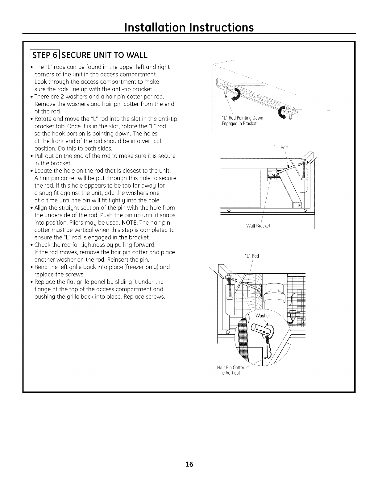
STEP 61SECURE UNIT TO WALL
• The "L" rods con be found in the upper left and right
corners of the unit in the access comportment.
Look through the access comportment to make
sure the rods line up with the anti-tip bracket.
• There ore 2 washers and a hair pin cotter per rod.
Remove the washers and hair pin cotter from the end
of the rod.
• Rotate and move the "L" rod into the slot in the anti-tip
bracket tab. Once it is in the slot, rotate the "L" rod
so the hook portion is pointing down. The holes
at the front end of the rod should be in a vertical
position. Do this to both sides.
• Pull out on the end of the rod to make sure it is secure
in the bracket.
• Locate the hole on the rod that isclosest to the unit.
A hair pin cotter will be put through this hole to secure
the rod. If this hole appears to be too for awau for
a snug fit against the unit, odd the washers one
at a time until the pin will fit tightly into the hole.
• Align the straight section of the pin with the hole from
the underside of the rod. Push the pin up until it snaps
into position. Pliers may be used. NOTE:The hair pin
cotter must be vertical when this step is completed to
ensure the "L" rod is engaged in the bracket.
• Check the rod for tightness bu pulling forward.
If the rod moves, remove the hair pin cotter and place
another washer on the rod. Reinsert the pin.
• Bend the left grille back into place (freezer onlu) and
replace the screws.
• Replace the flat grille panel bg sliding it under the
flange at the top of the access comportment and
pushing the grille back into place. Replace screws.
i - s-:.-...............i::
_'_-__ -_-_-, , - ............. -.
EJ "'::--- q _ £ <:_--_ " " " .
......._ --'- <_:_?s_-->..
"L" RodPointingDown _P [J
Engagedin Bracket
0
Wall Bracket
"L" Rod
\
/
/
"L" Rod
o
16
Washer
/
HairPinCotter --
isVertical
Page 17

Installation Instructions
[STEP 7 ADJUST DOOR SWING
NOTE:This refrigerotor hos o 2-position door stop.
When spoce does not ollow the door to swing open
fullg to 130°,gou mog chonge the door swing to o 90°
opening. Skip this step if door opening is satisfactory
for your installation situation.
PinLocation
For90°
DoorSwing
PinLocation
asShipped
For130°
DoorSwing
• Open the door to view the bottom hinge. Note
the door stop pin Iocotions. The pin isfoctorg-instolled
in the 130° position.
• Close the door. From below, use pliers to unscrew
the door stop ond reinstoll into the 90° position.
STEP 8 INSTALL GRILLE PANEL
(TRIMMED MODELS ONLY)
• Roisethe occess ponel to the stop position.
• Loosen the screws on the side trim behind the frome.
Remove the bottom trim.
• Slide the ponel over the metol boker ponel
ond into the trim.
• If necessorg, top with o wood block until the ponel
slips under the top trim piece.
• Reossemble the bottom trim. Tighten the screws.
• Adjust the hinge spring to occommodote the ponel
weight, if necessorg.
17
Page 18

Installation Instructions
[STEP 9] INSTALL FRAMED PANELS
(TRIMMED MODELS ONLY)
!! useFr0ntH0es
to SecureTrim
RearHoles
to SecureHandle
Install Door Panel:
• Open the door to 90°. Remove the 6 Phillips head screws
from the door handle.
• Remove the handle. Retain all screws.
• Remove the 6 screws holding the trim, lift off the trim.
Retain the screws.
• Slide the framed panel into the door trim.
Right hand models shown. Use the same instructions
for left hand models.
IF YOU ARE INSTALLING OVERLAY PANELS,
GO TO STEP IOA.
Handle
Trim
Standardsuppliedhandleshown
in 1/4"panel position.
• There are two sets of holes in the handle side trim.
Replace the handle side trim by installing the original
screws in the FRONTscrew holes.
• Secure the handle to the door using the REAR
screw holes.
DoorTrim
Door
k\\\\\\\\\\\\\\\\\\\%/
18
Page 19

Installation Instructions
STEP 9A INSTALL OVERLAY PANELS
Use Front Holes
to Secure Handle
UseRearHoles
to SecureTrim
Install Door Panel:
• Open the door to 90°. Remove the 6 Phillips head screws
from the door handle.
• Remove the handle. Retain all screws.
• Remove the 6 screws holding the trim, lift off the trim.
Retain the screws.
• Slide the overlay panel into the door trim.
Right hand models shown. Use the same instructions
for left hand models.
DoorTrim
Handle
Trim
Door
Move
Forward
For3/4"
Panel
Suppliedhandleshown
intheoverlaypanelposition.
• There are two sets of holes in the handle side trim.
Replace the handle side trim by installing the original
screws in the REARscrew holes.
• Secure the handle to the door using the FRONT
screw holes.
Custom Handles
If you are using custom handles, the handle must
be properly secured to the panel before sliding the panel
into the trim.
• The cabinet manufacturer will supply the custom
handle and hardware.
• Secure the door trim using new handle side trim.
Discard the supplied handle.
19
Page 20

Installation Instructions
STEP 10 CONNECT WATER SUPPLY
(FREEZERMODELS ONLY)
!
J
jJJ
.J
/'
(
"\ House
'_...Water Supply
• Locate and bring the tubing to the front
of the cabinet.
• Turn the water on to flush debris from the line.
Runabout a quart of water through the tubing
into a bucket, then shut off the water.
Copper Tubing:
• Slip a 1/4" nut and ferrule (provided) over both ends
of the copper tubing. Insert the tube into the union
fitting on the unit and tighten the nut to the union.
• Turn on the water to check for leaks.
GE SmartConnect TM Tubing:
• Insert the molded end of the tubing into
the refrigerator or freezer connection. Tighten
the compression nut until it isjust hand-tight.
• Tighten one additional turn with a wrench.
Overtightening can cause leaks!
• Turn on the water to check for leaks.
NOTE:Hake sure excess tubing length does not
interfere with the toekick installation.
.... L
Freezer /"
Water Supply /_
........ -JJ
//
\,
ISTEP 111 START ICEMAKER
Icemaker
/
/
Power
Switch
FeelerArm
• Slide the switch to ON. The icemaker will begin opera-
tion automatically.
• Be sure nothing interferes with the sweep
of the feeler arm.
• Discard the first full bucket of ice cubes.
• Toturn the icemaker off, slide the switch to OFF.
ISTEP12 INSTALL TOEKICK
• Locate the supplied toekick (shipped taped to the side
of the product). Install with 2 screws provided, adjust
to the desired height and tighten the screws.
• A custom toekick can be installed to match
or complement the surrounding cabinetry.
Use the supplied toekick as a template to cut
out the notch.
SuppliedToel<icl<
2O
1/4" orThickerToel<ick
IMPORTANT:The vented toekick must remain
unobstructed for proper air circulation and
operation.
Page 21

Notes
21
Page 22

Notes
22
Page 23

Notes
23
Page 24

NOTE: While performing installations described in this book,
safety glasses or goggles should be worn.
For Monogrom ® tocot service in your oreo, coil
1.800.444.1845.
NOTE: Product improvement is a continuing endeavor at
General Electric. Therefore, materials, appearance and
specifications are subject to change without notice.
]1-46148
22402601PO01
06-08 JR
Printed in the United States
GE Consumer & Industrial
Appliances
General Electric Company
Louisville, KY/40225
ge.com
 Loading...