

Page 1

Technical
Publication
Part Number 2300164-100
Revision 7
GE Medical Systems
Vivid™ 3 Pro/Vivid™ 3 Service Manual
Copyright© 2006 by GE Medical Systems
Page 2

GE MEDICAL SYSTEMS
IRECTION 2300164-100, REVISION 7VIVID™ 3 PRO/VIVID™ 3 SERVICE MANUAL
D
IMPORTANT PRECAUTIONS
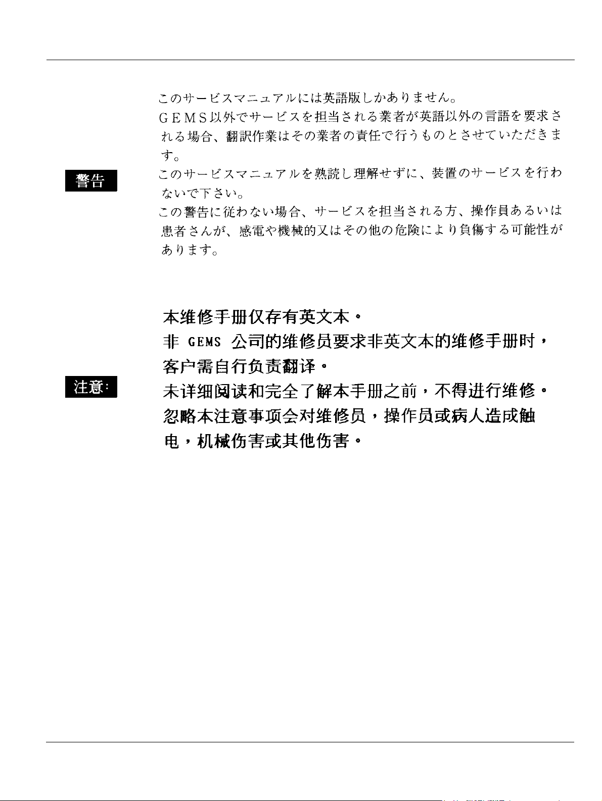
• THIS SERVICE MANUAL IS AVAILABLE IN ENGLISH ONLY.
• IF A CUSTOMER’S SERVICE PROVIDER REQUIRES A LANGUAGE OTHER THAN
ENGLISH, IT IS THE CUSTOMER’S RESPONSIBILITY TO PROVIDE
TRANSLATION SERVICES.
WARNING
AVERTISSEMENT
• DO NOT ATTEMPT TO SERVICE THE EQUIPMENT UNLESS THIS SERVICE
MANUAL HAS BEEN CONSULTED AND IS UNDERSTOOD.
• FAILURE TO HEED THIS WARNING MAY RESULT IN INJURY TO THE SERVICE
PROVIDER, OPERATOR OR PATIENT FROM ELECTRIC SHOCK, MECHANICAL
OR OTHER HAZARDS.
• CE MANUEL DE MAINTENANCE N’EST DISPONIBLE QU’EN ANGLAIS.
• SI LE TECHNICIEN DU CLIENT A BESOIN DE CE MANUEL DANS UNE AUTRE
LANGUE QUE L’ANGLAIS, C’EST AU CLIENT QU’IL INCOMBE DE LE FAIRE
TRADUIRE.
• NE PAS TENTER D’INTERVENTION SUR LES ÉQUIPEMENTS TANT QUE LE
MANUEL SERVICE N’A PAS ÉTÉ CONSULTÉ ET COMPRIS.
• LE NON-RESPECT DE CET AVERTISSEMENT PEUT ENTRAÎNER CHEZ LE
TECHNICIEN, L’OPÉRATEUR OU LE PATIENT DES BLESSURES DUES À DES
DANGERS ÉLECTRIQUES, MÉCANIQUES OU AUTRES.
WARNUNG
• DIESES KUNDENDIENST-HANDBUCH EXISTIERT NUR IN ENGLISCHER
SPRACHE.
• FALLS EIN FREMDER KUNDENDIENST EINE ANDERE SPRACHE BENÖTIGT, IST
ES AUFGABE DES KUNDEN FÜR EINE ENTSPRECHENDE ÜBERSETZUNG ZU
SORGEN.
• VERSUCHEN SIE NICHT, DAS GERÄT ZU REPARIEREN, BEVOR DIESES
KUNDENDIENST-HANDBUCH NICHT ZU RATE GEZOGEN UND VERSTANDEN
WURDE.
• WIRD DIESE WARNUNG NICHT BEACHTET, SO KANN ES ZU VERLETZUNGEN
DES KUNDENDIENSTTECHNIKERS, DES BEDIENERS ODER DES PATIENTEN
DURCH ELEKTRISCHE SCHLÄGE, MECHANISCHE ODER SONSTIGE
GEFAHREN KOMMEN.
i
Page 3

GE MEDICAL SYSTEMS
IRECTION 2300164-100, REVISION 7VIVID™ 3 PRO/VIVID™ 3 SERVICE MANUAL
D
• ESTE MANUAL DE SERVICIO SÓLO EXISTE EN INGLÉS.
• SI ALGÚN PROVEEDOR DE SERVICIOS AJENO A GEMS SOLICITA UN IDIOMA
QUE NO SEA EL INGLÉS, ES RESPONSABILIDAD DEL CLIENTE OFRECER UN
SERVICIO DE TRADUCCIÓN.
• NO SE DEBERÁ DAR SERVICIO TÉCNICO AL EQUIPO, SIN HABER
AV I S O
CONSULTADO Y COMPRENDIDO ESTE MANUAL DE SERVICIO.
• LA NO OBSERVANCIA DEL PRESENTE AVISO PUEDE DAR LUGAR A QUE EL
PROVEEDOR DE SERVICIOS, EL OPERADOR O EL PACIENTE SUFRAN
LESIONES PROVOCADAS POR CAUSAS ELÉCTRICAS, MECÁNICAS O DE OTRA
NATURALEZA.
• ESTE MANUAL DE ASSISTÊNCIA TÉCNICA SÓ SE ENCONTRA DISPONÍVEL EM
INGLÊS.
• SE QUALQUER OUTRO SERVIÇO DE ASSISTÊNCIA TÉCNICA, QUE NÃO A
GEMS, SOLICITAR ESTES MANUAIS NOUTRO IDIOMA, É DA
RESPONSABILIDADE DO CLIENTE FORNECER OS SERVIÇOS DE TRADUÇÃO.
ATENÇÃO
• NÃO TENTE REPARAR O EQUIPAMENTO SEM TER CONSULTADO E
COMPREENDIDO ESTE MANUAL DE ASSISTÊNCIA TÉCNICA.
• O NÃO CUMPRIMENTO DESTE AVISO PODE POR EM PERIGO A SEGURANÇA
DO TÉCNICO, OPERADOR OU PACIENTE DEVIDO A‘ CHOQUES ELÉTRICOS,
MECÂNICOS OU OUTROS.
AVVERTENZA
• IL PRESENTE MANUALE DI MANUTENZIONE È DISPONIBILE SOLTANTO IN
INGLESE.
• SE UN ADDETTO ALLA MANUTENZIONE ESTERNO ALLA GEMS RICHIEDE IL
MANUALE IN UNA LINGUA DIVERSA, IL CLIENTE È TENUTO A PROVVEDERE
DIRETTAMENTE ALLA TRADUZIONE.
• SI PROCEDA ALLA MANUTENZIONE DELL’APPARECCHIATURA SOLO DOPO
AVER CONSULTATO IL PRESENTE MANUALE ED AVERNE COMPRESO IL
CONTENUTO.
• NON TENERE CONTO DELLA PRESENTE AVVERTENZA POTREBBE FAR
COMPIERE OPERAZIONI DA CUI DERIVINO LESIONI ALL’ADDETTO ALLA
MANUTENZIONE, ALL’UTILIZZATORE ED AL PAZIENTE PER FOLGORAZIONE
ELETTRICA, PER URTI MECCANICI OD ALTRI RISCHI.
ii
Page 4
GE MEDICAL SYSTEMS
IRECTION 2300164-100, REVISION 7VIVID™ 3 PRO/VIVID™ 3 SERVICE MANUAL
D
iii
Page 5

GE MEDICAL SYSTEMS
IRECTION 2300164-100, REVISION 7VIVID™ 3 PRO/VIVID™ 3 SERVICE MANUAL
D
DAMAGE IN TRANSPORTATION
All packages should be closely examined at time of delivery. If damage is apparent write “Damage In
Shipment” on ALL copies of the freight or express bill BEFORE delivery is accepted or “signed for” by
a GE representative or hospital receiving agent. Whether noted or concealed, damage MUST be
reported to the carrier immediately upon discovery, or in any event, within 14 days after receipt, and the
contents and containers held for inspection by the carrier. A transportation company will not pay a claim
for damage if an inspection is not requested within this 14 day period.
CERTIFIED ELECTRICAL CONTRACTOR STATEMENT - FOR USA ONLY
All electrical Installations that are preliminary to positioning of the equipment at the site prepared for the
equipment shall be performed by licensed electrical contractors. Other connections between pieces of
electrical equipment, calibrations and testing shall be performed by qualified GE Medical Systems
personnel. In performing all electrical work on these products, GE will use its own specially trained field
engineers. All of GE’s electrical work on these products will comply with the requirements of the
applicable electrical codes.
The purchaser of GE equipment shall only utilize qualified personnel (i.e., GE’s field engineers,
personnel of third-party service companies with equivalent training, or licensed electricians) to perform
electrical servicing on the equipment.
OMISSIONS & ERRORS
If there are any omissions, errors or suggestions for improving this documentation, please contact the
GE Medical Systems Global Documentation Group with specific information listing the system type,
manual title, part number, revision number, page number and suggestion details. Mail the information
to: Service Documentation, 4855 W. Electric Ave (EA-53), Milwaukee, WI 53219, USA.
GE Medical Systems employees should use the iTrak System to report all documentation errors or
omissions.
iv
Page 6

GE MEDICAL SYSTEMS
IRECTION 2300164-100, REVISION 7VIVID™ 3 PRO/VIVID™ 3 SERVICE MANUAL
D
LEGAL NOTES
The contents of this publication may not be copied or duplicated in any form, in whole or in part, without
prior written permission of GE Medical Systems.
GE Medical Systems may revise this publication from time to time without written notice.
TRADEMARKS
All products and their name brands are trademarks of their respective holders.
COPYRIGHTS
All Material Copyright© 2006 by General Electric Inc. All Rights Reserved
v
Page 7

GE MEDICAL SYSTEMS
IRECTION 2300164-100, REVISION 7VIVID™ 3 PRO/VIVID™ 3 SERVICE MANUAL
D
Revision History
Revision Date Reason for change
0 2002 Initial Release
1 April 2002 Second Release
2 November 2002 Third Release
3 September 2003 Fourth Release
4 December 2003 New Breakthrough
5 March 2004 Hardware Modifications; Corrections
6 July 2005 Updated System Labels;
added Waste Electrical and Electronic Equipment (WEEE) Disposal warning
7 February 2006 Software Upgrade
List of Effected Pages
Pages Revision Pages Revision Pages Revision
Title Page N/A
Important Precautions
pages i to iv
Legal / Rev History/LOEP
pages v to vi
Table of Contents
pages vii to xxii
Chapter 1 - Introduction
pages 1-1 to 1-28
vi
7
7
7
7
Chapter 2 - Pre-Installation
pages 2-1 to 2.12
Chapter 3 - Installation
pages 3-1 to 3-78
Chapter 4 - Functional Checks
pages 4-1 to 4-34
Chapter 5 - Theory
pages 5-1 to 5-52
Chapter 6 - Service Adjustments
pages 6-1 to 6-18
Chapter 7 - Diagnostics/
7
7
7
Chapter 10 - Periodic Maintenance
7
7 Back Cover N/A
Troubleshooting
pages 7-1 to 7-130
Chapter 8 - Replacement
Procedures
pages 8-1 to 8-190
Chapter 9 - Replacement Parts
pages 9-1 to 9-38
pages 10-1 to 10-32
7
7
7
7
Page 8

GE MEDICAL SYSTEMS DIRECTION 2300164-100, REVISION 7 VIVID™ 3 PRO/VIVID™ 3 SERVICE MANUAL
Table of Contents
CHAPTER 1
Introduction
Overview . . . . . . . . . . . . . . . . . . . . . . . . . . . . . . . . . . . . . . . . . . . . . . . . . . . . . . . . . 1 - 1
Purpose of Chapter 1 . . . . . . . . . . . . . . . . . . . . . . . . . . . . . . . . . . . . . . . . . . 1 - 1
Purpose of Service Manual . . . . . . . . . . . . . . . . . . . . . . . . . . . . . . . . . . . . . 1 - 1
Typical Users of the Basic Service Manual . . . . . . . . . . . . . . . . . . . . . . . . . 1 - 2
Vivid™ 3 Models Covered in this Manual . . . . . . . . . . . . . . . . . . . . . . . . . . 1 - 3
System History - Hardware and Software Versions . . . . . . . . . . . . . . . . . . . 1 - 5
Purpose of Operator Manual(s) . . . . . . . . . . . . . . . . . . . . . . . . . . . . . . . . . . 1 - 5
Important Conventions. . . . . . . . . . . . . . . . . . . . . . . . . . . . . . . . . . . . . . . . . . . . . . . 1 - 6
Conventions Used in this Manual . . . . . . . . . . . . . . . . . . . . . . . . . . . . . . . . . 1 - 6
Safety Considerations . . . . . . . . . . . . . . . . . . . . . . . . . . . . . . . . . . . . . . . . . . . . . . . 1 - 8
Introduction . . . . . . . . . . . . . . . . . . . . . . . . . . . . . . . . . . . . . . . . . . . . . . . . . 1 - 8
Human Safety . . . . . . . . . . . . . . . . . . . . . . . . . . . . . . . . . . . . . . . . . . . . . . . 1 - 8
Mechanical Safety . . . . . . . . . . . . . . . . . . . . . . . . . . . . . . . . . . . . . . . . . . . . 1 - 8
Electrical Safety . . . . . . . . . . . . . . . . . . . . . . . . . . . . . . . . . . . . . . . . . . . . . . 1 - 9
Dangerous Procedure Warnings . . . . . . . . . . . . . . . . . . . . . . . . . . . . . . . . . 1 - 10
Product Labels and Icons . . . . . . . . . . . . . . . . . . . . . . . . . . . . . . . . . . . . . . . . . . . . 1 - 11
Product Label Locations . . . . . . . . . . . . . . . . . . . . . . . . . . . . . . . . . . . . . . . . 1 - 11
Label Descriptions . . . . . . . . . . . . . . . . . . . . . . . . . . . . . . . . . . . . . . . . . . . . 1 - 13
Vivid™ 3 External Labels . . . . . . . . . . . . . . . . . . . . . . . . . . . . . . . . . . . . . . . 1 - 15
EMC, EMI, and ESD . . . . . . . . . . . . . . . . . . . . . . . . . . . . . . . . . . . . . . . . . . . . . . . . 1 - 25
Electromagnetic Compatibility (EMC) . . . . . . . . . . . . . . . . . . . . . . . . . . . . . 1 - 25
Electrostatic Discharge (ESD) Prevention . . . . . . . . . . . . . . . . . . . . . . . . . . 1 - 25
Standards Used . . . . . . . . . . . . . . . . . . . . . . . . . . . . . . . . . . . . . . . . . . . . . . 1 - 26
Lockout/Tagout Requirements (For USA Only) . . . . . . . . . . . . . . . . . . . . . . 1 - 26
Customer Assistance . . . . . . . . . . . . . . . . . . . . . . . . . . . . . . . . . . . . . . . . . . . . . . . . 1 - 27
Contact Information . . . . . . . . . . . . . . . . . . . . . . . . . . . . . . . . . . . . . . . . . . . 1 - 27
Table of Contents vii
Page 9

GE MEDICAL SYSTEMS
IRECTION 2300164-100, REVISION 7VIVID™ 3 PRO/VIVID™ 3 SERVICE MANUAL
D
CHAPTER 2
Pre-Installation
Overview . . . . . . . . . . . . . . . . . . . . . . . . . . . . . . . . . . . . . . . . . . . . . . . . . . . . . . . . . 2 - 1
Purpose of Chapter 2 . . . . . . . . . . . . . . . . . . . . . . . . . . . . . . . . . . . . . . . . . . 2 - 1
Console Requirements . . . . . . . . . . . . . . . . . . . . . . . . . . . . . . . . . . . . . . . . . . . . . . 2 - 2
Unit Environmental Requirements . . . . . . . . . . . . . . . . . . . . . . . . . . . . . . . . 2 - 2
Cooling Requirements . . . . . . . . . . . . . . . . . . . . . . . . . . . . . . . . . . . . . . . . . 2 - 2
Lighting Requirements . . . . . . . . . . . . . . . . . . . . . . . . . . . . . . . . . . . . . . . . . 2 - 2
Time and Manpower Requirements . . . . . . . . . . . . . . . . . . . . . . . . . . . . . . . 2 - 2
Electrical Requirements . . . . . . . . . . . . . . . . . . . . . . . . . . . . . . . . . . . . . . . . 2 - 3
EMI Limitations . . . . . . . . . . . . . . . . . . . . . . . . . . . . . . . . . . . . . . . . . . . . . . . 2 - 5
Probe Environmental Requirements . . . . . . . . . . . . . . . . . . . . . . . . . . . . . . 2 - 6
Facility Needs . . . . . . . . . . . . . . . . . . . . . . . . . . . . . . . . . . . . . . . . . . . . . . . . . . . . . 2 - 7
Purchaser Responsibilities . . . . . . . . . . . . . . . . . . . . . . . . . . . . . . . . . . . . . . 2 - 7
Mandatory Site Requirements . . . . . . . . . . . . . . . . . . . . . . . . . . . . . . . . . . . 2 - 8
Site Recommendations . . . . . . . . . . . . . . . . . . . . . . . . . . . . . . . . . . . . . . . . 2 - 8
Networking Pre-Installation Requirements . . . . . . . . . . . . . . . . . . . . . . . . . . 2 - 9
Connectivity Installation Worksheet . . . . . . . . . . . . . . . . . . . . . . . . . . . . . . . . . . . . . 2 - 11
viii
Page 10

GE MEDICAL SYSTEMS
IRECTION 2300164-100, REVISION 7VIVID™ 3 PRO/VIVID™ 3 SERVICE MANUAL
D
CHAPTER 3
Installation
Overview. . . . . . . . . . . . . . . . . . . . . . . . . . . . . . . . . . . . . . . . . . . . . . . . . . . . . . . . . 3 - 1
Purpose of Chapter 3 . . . . . . . . . . . . . . . . . . . . . . . . . . . . . . . . . . . . . . . . . 3 - 1
Installation Reminders . . . . . . . . . . . . . . . . . . . . . . . . . . . . . . . . . . . . . . . . . . . . . . 3 - 2
Average Installation Time . . . . . . . . . . . . . . . . . . . . . . . . . . . . . . . . . . . . . . 3 - 2
Installation Warnings . . . . . . . . . . . . . . . . . . . . . . . . . . . . . . . . . . . . . . . . . 3 - 2
Safety Reminders . . . . . . . . . . . . . . . . . . . . . . . . . . . . . . . . . . . . . . . . . . . . 3 - 3
Receiving and Unpacking the Equipment. . . . . . . . . . . . . . . . . . . . . . . . . . . . . . . . 3 - 4
Unpacking the Wooden Shipping Crate . . . . . . . . . . . . . . . . . . . . . . . . . . . 3 - 4
Unpacking the Cardboard Shipping Carton . . . . . . . . . . . . . . . . . . . . . . . . 3 - 9
Unpacking and Removing the Unit from the Cardboard Shipping Carton . 3 - 9
Preparing for Installation. . . . . . . . . . . . . . . . . . . . . . . . . . . . . . . . . . . . . . . . . . . . . 3 - 13
Confirming Customer Order . . . . . . . . . . . . . . . . . . . . . . . . . . . . . . . . . . . . 3 - 13
Verifying the Shipping Crate Contents . . . . . . . . . . . . . . . . . . . . . . . . . . . . 3 - 13
Component Inspection . . . . . . . . . . . . . . . . . . . . . . . . . . . . . . . . . . . . . . . . 3 - 14
System Voltage Confirmation . . . . . . . . . . . . . . . . . . . . . . . . . . . . . . . . . . . 3 - 19
Video Formats Confirmation . . . . . . . . . . . . . . . . . . . . . . . . . . . . . . . . . . . . 3 - 20
Ensuring Protection from EMI . . . . . . . . . . . . . . . . . . . . . . . . . . . . . . . . . . . 3 - 21
Completing the Hardware Installation. . . . . . . . . . . . . . . . . . . . . . . . . . . . . . . . . . . 3 - 22
Connecting the Footswitch . . . . . . . . . . . . . . . . . . . . . . . . . . . . . . . . . . . . . 3 - 22
Connecting Peripherals . . . . . . . . . . . . . . . . . . . . . . . . . . . . . . . . . . . . . . . 3 - 23
Connecting Probes . . . . . . . . . . . . . . . . . . . . . . . . . . . . . . . . . . . . . . . . . . . 3 - 28
Connecting the ECG . . . . . . . . . . . . . . . . . . . . . . . . . . . . . . . . . . . . . . . . . . 3 - 29
Connecting the Unit to a Power Source . . . . . . . . . . . . . . . . . . . . . . . . . . . 3 - 31
Switching the System ON/OFF . . . . . . . . . . . . . . . . . . . . . . . . . . . . . . . . . . 3 - 33
System Configuration . . . . . . . . . . . . . . . . . . . . . . . . . . . . . . . . . . . . . . . . . . . . . . . 3 - 35
Adjusting the Display Monitor . . . . . . . . . . . . . . . . . . . . . . . . . . . . . . . . . . . 3 - 35
Hospital Info Tab . . . . . . . . . . . . . . . . . . . . . . . . . . . . . . . . . . . . . . . . . . . . . 3 - 35
System Tab . . . . . . . . . . . . . . . . . . . . . . . . . . . . . . . . . . . . . . . . . . . . . . . . . 3 - 36
Connectivity Tab . . . . . . . . . . . . . . . . . . . . . . . . . . . . . . . . . . . . . . . . . . . . . 3 - 37
Archive Tab . . . . . . . . . . . . . . . . . . . . . . . . . . . . . . . . . . . . . . . . . . . . . . . . . 3 - 37
Annotation Settings Tab . . . . . . . . . . . . . . . . . . . . . . . . . . . . . . . . . . . . . . . 3 - 39
System Options Tab . . . . . . . . . . . . . . . . . . . . . . . . . . . . . . . . . . . . . . . . . . 3 - 41
Printers Tab . . . . . . . . . . . . . . . . . . . . . . . . . . . . . . . . . . . . . . . . . . . . . . . . 3 - 43
ix
Page 11

GE MEDICAL SYSTEMS
IRECTION 2300164-100, REVISION 7VIVID™ 3 PRO/VIVID™ 3 SERVICE MANUAL
D
VCR/ECG Tab . . . . . . . . . . . . . . . . . . . . . . . . . . . . . . . . . . . . . . . . . . . . . . . 3 - 45
Technical Support Tab . . . . . . . . . . . . . . . . . . . . . . . . . . . . . . . . . . . . . . . . . 3 - 47
Technical Support History Tab . . . . . . . . . . . . . . . . . . . . . . . . . . . . . . . . . . . 3 - 49
Connectivity Setup . . . . . . . . . . . . . . . . . . . . . . . . . . . . . . . . . . . . . . . . . . . . . . . . . . 3 - 50
Introduction . . . . . . . . . . . . . . . . . . . . . . . . . . . . . . . . . . . . . . . . . . . . . . . . . 3 - 50
Physical Connection . . . . . . . . . . . . . . . . . . . . . . . . . . . . . . . . . . . . . . . . . . . 3 - 50
Setting Up for Connectivity . . . . . . . . . . . . . . . . . . . . . . . . . . . . . . . . . . . . . . 3 - 52
Setting Up the Network Connection . . . . . . . . . . . . . . . . . . . . . . . . . . . . . . . 3 - 55
Setting Up for Communication with a Prosolv Workstation . . . . . . . . . . . . . 3 - 57
Connecting Directly to EchoPAC . . . . . . . . . . . . . . . . . . . . . . . . . . . . . . . . . 3 - 63
Storing and Transporting the Unit . . . . . . . . . . . . . . . . . . . . . . . . . . . . . . . . . . . . . . 3 - 68
Disconnecting the Unit when Storing . . . . . . . . . . . . . . . . . . . . . . . . . . . . . . 3 - 68
Preparing the Unit for Transport . . . . . . . . . . . . . . . . . . . . . . . . . . . . . . . . . . 3 - 68
Safety Precautions for Moving the Vivid™ 3 Unit . . . . . . . . . . . . . . . . . . . . 3 - 69
Wooden Shipping Crate and Packaging Materials . . . . . . . . . . . . . . . . . . . . 3 - 69
Cardboard Shipping Carton and Packaging Materials . . . . . . . . . . . . . . . . . 3 - 70
Packing the Unit into the Wooden Shipping Crate . . . . . . . . . . . . . . . . . . . . 3 - 71
Assembling the Wooden Shipping Crate . . . . . . . . . . . . . . . . . . . . . . . . . . . 3 - 72
Packing the Unit in the Cardboard Shipping Carton . . . . . . . . . . . . . . . . . . 3 - 74
Assembling the Cardboard Shipping Carton . . . . . . . . . . . . . . . . . . . . . . . . 3 - 75
Completing the Installation Paperwork . . . . . . . . . . . . . . . . . . . . . . . . . . . . . . . . . . 3 - 76
System Installation Details . . . . . . . . . . . . . . . . . . . . . . . . . . . . . . . . . . . . . . 3 - 76
Product Locator Installation . . . . . . . . . . . . . . . . . . . . . . . . . . . . . . . . . . . . . 3 - 76
User Manual(s) . . . . . . . . . . . . . . . . . . . . . . . . . . . . . . . . . . . . . . . . . . . . . . . 3 - 77
x
Page 12

GE MEDICAL SYSTEMS
IRECTION 2300164-100, REVISION 7VIVID™ 3 PRO/VIVID™ 3 SERVICE MANUAL
D
CHAPTER 4
Functional Checks
Overview. . . . . . . . . . . . . . . . . . . . . . . . . . . . . . . . . . . . . . . . . . . . . . . . . . . . . . . . . 4 - 1
Purpose of Chapter 4 . . . . . . . . . . . . . . . . . . . . . . . . . . . . . . . . . . . . . . . . . 4 - 1
General Procedures . . . . . . . . . . . . . . . . . . . . . . . . . . . . . . . . . . . . . . . . . . . . . . . . 4 - 2
Power ON/OFF and Boot-up Tests . . . . . . . . . . . . . . . . . . . . . . . . . . . . . . . 4 - 2
Diagnostic Power Supply Test . . . . . . . . . . . . . . . . . . . . . . . . . . . . . . . . . . 4 - 2
Functional Check . . . . . . . . . . . . . . . . . . . . . . . . . . . . . . . . . . . . . . . . . . . . . . . . . . 4 - 3
Basic Controls . . . . . . . . . . . . . . . . . . . . . . . . . . . . . . . . . . . . . . . . . . . . . . . 4 - 3
Peripherals . . . . . . . . . . . . . . . . . . . . . . . . . . . . . . . . . . . . . . . . . . . . . . . . . 4 - 4
Mechanical Functions . . . . . . . . . . . . . . . . . . . . . . . . . . . . . . . . . . . . . . . . . 4 - 6
Back End Processor Tests . . . . . . . . . . . . . . . . . . . . . . . . . . . . . . . . . . . . . 4 - 7
Image Testing: 2D/M/CFM/Doppler . . . . . . . . . . . . . . . . . . . . . . . . . . . . . . . . . . . . 4 - 11
3S Probe Image Quality Tests . . . . . . . . . . . . . . . . . . . . . . . . . . . . . . . . . . 4 - 11
7S Probe Image Quality Tests . . . . . . . . . . . . . . . . . . . . . . . . . . . . . . . . . . 4 - 18
C358 Curved Probe Image Quality Tests . . . . . . . . . . . . . . . . . . . . . . . . . . 4 - 19
739L Probe Image Quality Tests . . . . . . . . . . . . . . . . . . . . . . . . . . . . . . . . 4 - 21
Probe 10S Image Quality Tests . . . . . . . . . . . . . . . . . . . . . . . . . . . . . . . . . 4 - 25
2D (Pencil) Probe Image Quality Test . . . . . . . . . . . . . . . . . . . . . . . . . . . . 4 - 25
System Turnover Checklist. . . . . . . . . . . . . . . . . . . . . . . . . . . . . . . . . . . . . . . . . . . 4 - 26
Software Configuration Checks . . . . . . . . . . . . . . . . . . . . . . . . . . . . . . . . . 4 - 26
Site Log . . . . . . . . . . . . . . . . . . . . . . . . . . . . . . . . . . . . . . . . . . . . . . . . . . . . . . . . . 4 - 33
xi
Page 13

GE MEDICAL SYSTEMS
IRECTION 2300164-100, REVISION 7VIVID™ 3 PRO/VIVID™ 3 SERVICE MANUAL
D
CHAPTER 5
Components and Function (Theory)
Overview . . . . . . . . . . . . . . . . . . . . . . . . . . . . . . . . . . . . . . . . . . . . . . . . . . . . . . . . . 5 - 1
Purpose of Chapter 5 . . . . . . . . . . . . . . . . . . . . . . . . . . . . . . . . . . . . . . . . . . 5 - 1
General Information . . . . . . . . . . . . . . . . . . . . . . . . . . . . . . . . . . . . . . . . . . . . . . . . . 5 - 2
Block Diagrams . . . . . . . . . . . . . . . . . . . . . . . . . . . . . . . . . . . . . . . . . . . . . . . . . . . . 5 - 3
System Block Diagrams . . . . . . . . . . . . . . . . . . . . . . . . . . . . . . . . . . . . . . . . 5 - 3
Front End . . . . . . . . . . . . . . . . . . . . . . . . . . . . . . . . . . . . . . . . . . . . . . . . . . . . . . . . . 5 - 7
General Information . . . . . . . . . . . . . . . . . . . . . . . . . . . . . . . . . . . . . . . . . . . 5 - 7
Front Board Assembly (FB) . . . . . . . . . . . . . . . . . . . . . . . . . . . . . . . . . . . . . 5 - 16
MUX Board . . . . . . . . . . . . . . . . . . . . . . . . . . . . . . . . . . . . . . . . . . . . . . . . . . 5 - 18
Beamformer Board (BF) . . . . . . . . . . . . . . . . . . . . . . . . . . . . . . . . . . . . . . . . 5 - 19
Radio Frequency Interface (RFI) Board . . . . . . . . . . . . . . . . . . . . . . . . . . . . 5 - 20
Front End Controller Board (FEC) (RFT) . . . . . . . . . . . . . . . . . . . . . . . . . . . 5 - 23
RF and Tissue Processor Board (RFT) . . . . . . . . . . . . . . . . . . . . . . . . . . . . 5 - 24
Image Port Board (IMP) . . . . . . . . . . . . . . . . . . . . . . . . . . . . . . . . . . . . . . . . 5 - 25
Back Plane Board (Motherboard) . . . . . . . . . . . . . . . . . . . . . . . . . . . . . . . . . 5 - 25
Back End Processor . . . . . . . . . . . . . . . . . . . . . . . . . . . . . . . . . . . . . . . . . . . . . . . . 5 - 26
Introduction . . . . . . . . . . . . . . . . . . . . . . . . . . . . . . . . . . . . . . . . . . . . . . . . . 5 - 26
Central Processing Unit (CPU) . . . . . . . . . . . . . . . . . . . . . . . . . . . . . . . . . . 5 - 31
Keyboard Controller . . . . . . . . . . . . . . . . . . . . . . . . . . . . . . . . . . . . . . . . . . . 5 - 34
Multifunction I/O Controller . . . . . . . . . . . . . . . . . . . . . . . . . . . . . . . . . . . . . 5 - 35
Frame Grabber (RFI systems only) . . . . . . . . . . . . . . . . . . . . . . . . . . . . . . . 5 - 35
PC2IP . . . . . . . . . . . . . . . . . . . . . . . . . . . . . . . . . . . . . . . . . . . . . . . . . . . . . . 5 - 35
Plug and Scan Card and Battery . . . . . . . . . . . . . . . . . . . . . . . . . . . . . . . . . 5 - 35
Network Onboard . . . . . . . . . . . . . . . . . . . . . . . . . . . . . . . . . . . . . . . . . . . . . 5 - 35
SCSI Card . . . . . . . . . . . . . . . . . . . . . . . . . . . . . . . . . . . . . . . . . . . . . . . . . . 5 - 35
Floppy Drive . . . . . . . . . . . . . . . . . . . . . . . . . . . . . . . . . . . . . . . . . . . . . . . . . 5 - 36
Hard Disk . . . . . . . . . . . . . . . . . . . . . . . . . . . . . . . . . . . . . . . . . . . . . . . . . . . 5 - 36
Magneto-Optical Drive (MOD) . . . . . . . . . . . . . . . . . . . . . . . . . . . . . . . . . . . 5 - 37
CD Read Write (CDRW) . . . . . . . . . . . . . . . . . . . . . . . . . . . . . . . . . . . . . . . 5 - 37
ECG Module . . . . . . . . . . . . . . . . . . . . . . . . . . . . . . . . . . . . . . . . . . . . . . . . . 5 - 37
Modem . . . . . . . . . . . . . . . . . . . . . . . . . . . . . . . . . . . . . . . . . . . . . . . . . . . . . 5 - 38
PC-VIC Assembly . . . . . . . . . . . . . . . . . . . . . . . . . . . . . . . . . . . . . . . . . . . . 5 - 39
External Peripherals. . . . . . . . . . . . . . . . . . . . . . . . . . . . . . . . . . . . . . . . . . . . . . . . . 5 - 41
xii
Page 14

GE MEDICAL SYSTEMS
IRECTION 2300164-100, REVISION 7VIVID™ 3 PRO/VIVID™ 3 SERVICE MANUAL
D
Introduction . . . . . . . . . . . . . . . . . . . . . . . . . . . . . . . . . . . . . . . . . . . . . . . . . 5 - 41
Vivid™ 3 Power Distribution . . . . . . . . . . . . . . . . . . . . . . . . . . . . . . . . . . . . . . . . . . 5 - 42
Electrical Power . . . . . . . . . . . . . . . . . . . . . . . . . . . . . . . . . . . . . . . . . . . . . 5 - 42
AC System . . . . . . . . . . . . . . . . . . . . . . . . . . . . . . . . . . . . . . . . . . . . . . . . . 5 - 43
AC Distribution Box . . . . . . . . . . . . . . . . . . . . . . . . . . . . . . . . . . . . . . . . . . . 5 - 45
Front End DC Power Distribution . . . . . . . . . . . . . . . . . . . . . . . . . . . . . . . . 5 - 47
Front End Cooling System . . . . . . . . . . . . . . . . . . . . . . . . . . . . . . . . . . . . . . . . . . . 5 - 49
General Description . . . . . . . . . . . . . . . . . . . . . . . . . . . . . . . . . . . . . . . . . . 5 - 49
Location in the Unit . . . . . . . . . . . . . . . . . . . . . . . . . . . . . . . . . . . . . . . . . . . 5 - 49
Common Service Platform . . . . . . . . . . . . . . . . . . . . . . . . . . . . . . . . . . . . . . . . . . . 5 - 50
Introduction . . . . . . . . . . . . . . . . . . . . . . . . . . . . . . . . . . . . . . . . . . . . . . . . . 5 - 50
iLinq Interactive Platform Features . . . . . . . . . . . . . . . . . . . . . . . . . . . . . . . 5 - 50
Global Service User Interface (GSUI) . . . . . . . . . . . . . . . . . . . . . . . . . . . . . 5 - 51
xiii
Page 15

GE MEDICAL SYSTEMS
IRECTION 2300164-100, REVISION 7VIVID™ 3 PRO/VIVID™ 3 SERVICE MANUAL
D
CHAPTER 6
Service Adjustments
Overview . . . . . . . . . . . . . . . . . . . . . . . . . . . . . . . . . . . . . . . . . . . . . . . . . . . . . . . . . 6 - 1
Purpose of Chapter 6 . . . . . . . . . . . . . . . . . . . . . . . . . . . . . . . . . . . . . . . . . . 6 - 1
Input AC Voltage Configuration . . . . . . . . . . . . . . . . . . . . . . . . . . . . . . . . . . . . . . . . 6 - 2
Secondary Voltage Configuration . . . . . . . . . . . . . . . . . . . . . . . . . . . . . . . . 6 - 2
AC Input Cord . . . . . . . . . . . . . . . . . . . . . . . . . . . . . . . . . . . . . . . . . . . . . . . 6 - 2
Front End Voltages and Signal Indicators . . . . . . . . . . . . . . . . . . . . . . . . . . . . . . . . 6 - 3
RFI LEDs . . . . . . . . . . . . . . . . . . . . . . . . . . . . . . . . . . . . . . . . . . . . . . . . . . . 6 - 5
Image Port (IMP) LEDs . . . . . . . . . . . . . . . . . . . . . . . . . . . . . . . . . . . . . . . . 6 - 5
Front End Controller (FEC) LEDs . . . . . . . . . . . . . . . . . . . . . . . . . . . . . . . . 6 - 6
RF and Tissue Processor (RFT) . . . . . . . . . . . . . . . . . . . . . . . . . . . . . . . . . 6 - 6
Beamformer (BF) . . . . . . . . . . . . . . . . . . . . . . . . . . . . . . . . . . . . . . . . . . . . . 6 - 6
Channels Multiplexer (MUX) . . . . . . . . . . . . . . . . . . . . . . . . . . . . . . . . . . . . 6 - 7
Front Board Assembly (FB) . . . . . . . . . . . . . . . . . . . . . . . . . . . . . . . . . . . . . 6 - 7
Back End Power Supply Voltages . . . . . . . . . . . . . . . . . . . . . . . . . . . . . . . . . . . . . . 6 - 8
VIC Video Signal Setting . . . . . . . . . . . . . . . . . . . . . . . . . . . . . . . . . . . . . . . . . . . . . 6 - 8
Video Format Confirmation . . . . . . . . . . . . . . . . . . . . . . . . . . . . . . . . . . . . . 6 - 8
Monitor Operation . . . . . . . . . . . . . . . . . . . . . . . . . . . . . . . . . . . . . . . . . . . . . . . . . . 6 - 9
Vivid™ 3 Samsung 15" and 17" Monitor Operation . . . . . . . . . . . . . . . . . . . 6 - 9
Image Quality Calibration. . . . . . . . . . . . . . . . . . . . . . . . . . . . . . . . . . . . . . . . . . . . . 6 - 12
Image Quality Calibration for the Vivid™ 3 15" and 17" Samsung Monitors 6 - 12
Calibration . . . . . . . . . . . . . . . . . . . . . . . . . . . . . . . . . . . . . . . . . . . . . . . . . . . . . . . . 6 - 14
Accessing the Calibration Options . . . . . . . . . . . . . . . . . . . . . . . . . . . . . . . . 6 - 14
Monitor Calibration . . . . . . . . . . . . . . . . . . . . . . . . . . . . . . . . . . . . . . . . . . . . 6 - 16
Beamformer Calibration . . . . . . . . . . . . . . . . . . . . . . . . . . . . . . . . . . . . . . . . 6 - 17
Video Grabbing Calibration . . . . . . . . . . . . . . . . . . . . . . . . . . . . . . . . . . . . . 6 - 17
xiv
Page 16

GE MEDICAL SYSTEMS
IRECTION 2300164-100, REVISION 7VIVID™ 3 PRO/VIVID™ 3 SERVICE MANUAL
D
CHAPTER 7
Diagnostics/Troubleshooting
Overview. . . . . . . . . . . . . . . . . . . . . . . . . . . . . . . . . . . . . . . . . . . . . . . . . . . . . . . . . 7 - 1
Purpose of Chapter . . . . . . . . . . . . . . . . . . . . . . . . . . . . . . . . . . . . . . . . . . . 7 - 1
Diagnostics . . . . . . . . . . . . . . . . . . . . . . . . . . . . . . . . . . . . . . . . . . . . . . . . . . . . . . . 7 - 2
Diagnostic Tools . . . . . . . . . . . . . . . . . . . . . . . . . . . . . . . . . . . . . . . . . . . . . 7 - 2
Diagnostic Procedure Summary . . . . . . . . . . . . . . . . . . . . . . . . . . . . . . . . . 7 - 2
Accessing the Diagnostic Menu . . . . . . . . . . . . . . . . . . . . . . . . . . . . . . . . . 7 - 3
Performing Front End (FE) Diagnostics . . . . . . . . . . . . . . . . . . . . . . . . . . . . . . . . . 7 - 5
Accessing the Front End Diagnostic Options . . . . . . . . . . . . . . . . . . . . . . . 7 - 6
Radio Frequency Interface (RFI) Diagnostic Tests (for RFI Configuration) 7 - 11
Image Port (IMP) Diagnostic Tests (for RFT Configuration) . . . . . . . . . . . . 7 - 13
VME Bus (VME) Diagnostic Tests (for RFT Configuration) . . . . . . . . . . . . 7 - 15
RFT Diagnostic Tests (for RFT Configuration) . . . . . . . . . . . . . . . . . . . . . . 7 - 17
Front End Controller (FEC) Diagnostic Tests (for RFT Configuration) . . . . 7 - 19
Beamformer (BF) Diagnostic Tests . . . . . . . . . . . . . . . . . . . . . . . . . . . . . . 7 - 21
Front Board Assembly (FB) Diagnostic Tests . . . . . . . . . . . . . . . . . . . . . . . 7 - 25
MUX Diagnostic Tests . . . . . . . . . . . . . . . . . . . . . . . . . . . . . . . . . . . . . . . . 7 - 47
H/W Report . . . . . . . . . . . . . . . . . . . . . . . . . . . . . . . . . . . . . . . . . . . . . . . . . 7 - 66
Current Report . . . . . . . . . . . . . . . . . . . . . . . . . . . . . . . . . . . . . . . . . . . . . . 7 - 67
Performing Back End Diagnostics on the System . . . . . . . . . . . . . . . . . . . . . . . . . 7 - 68
Accessing the Back End Diagnostic Options . . . . . . . . . . . . . . . . . . . . . . . 7 - 68
Audio (Doppler Sound Driver) Diagnostic Test . . . . . . . . . . . . . . . . . . . . . . 7 - 70
ECG/Phono Diagnostic Test . . . . . . . . . . . . . . . . . . . . . . . . . . . . . . . . . . . . 7 - 71
External Keyboard Diagnostic Test . . . . . . . . . . . . . . . . . . . . . . . . . . . . . . 7 - 73
Keyboard Diagnostic Test . . . . . . . . . . . . . . . . . . . . . . . . . . . . . . . . . . . . . . 7 - 76
Media Driver Diagnostic Test . . . . . . . . . . . . . . . . . . . . . . . . . . . . . . . . . . . 7 - 77
Computer Diagnostic Test . . . . . . . . . . . . . . . . . . . . . . . . . . . . . . . . . . . . . 7 - 79
UPS Test . . . . . . . . . . . . . . . . . . . . . . . . . . . . . . . . . . . . . . . . . . . . . . . . . . 7 - 82
Checking the Network Adaptors from Windows Device Manager . . . . . . . 7 - 83
Common Service Interface . . . . . . . . . . . . . . . . . . . . . . . . . . . . . . . . . . . . . . . . . . . 7 - 84
iLinq Interactive Platform Features . . . . . . . . . . . . . . . . . . . . . . . . . . . . . . . 7 - 84
Global Service User Interface . . . . . . . . . . . . . . . . . . . . . . . . . . . . . . . . . . . 7 - 84
Error Logs Page . . . . . . . . . . . . . . . . . . . . . . . . . . . . . . . . . . . . . . . . . . . . . 7 - 88
Diagnostics Page . . . . . . . . . . . . . . . . . . . . . . . . . . . . . . . . . . . . . . . . . . . . 7 - 96
Image Quality Page . . . . . . . . . . . . . . . . . . . . . . . . . . . . . . . . . . . . . . . . . . 7 - 109
xv
Page 17

GE MEDICAL SYSTEMS
IRECTION 2300164-100, REVISION 7VIVID™ 3 PRO/VIVID™ 3 SERVICE MANUAL
D
Calibration Page . . . . . . . . . . . . . . . . . . . . . . . . . . . . . . . . . . . . . . . . . . . . . . 7 - 109
Configuration Page . . . . . . . . . . . . . . . . . . . . . . . . . . . . . . . . . . . . . . . . . . . 7 - 110
Utilities Page . . . . . . . . . . . . . . . . . . . . . . . . . . . . . . . . . . . . . . . . . . . . . . . . 7 - 111
Replacement Page . . . . . . . . . . . . . . . . . . . . . . . . . . . . . . . . . . . . . . . . . . . . 7 - 125
PM Page . . . . . . . . . . . . . . . . . . . . . . . . . . . . . . . . . . . . . . . . . . . . . . . . . . . 7 - 125
Automatic Error Log . . . . . . . . . . . . . . . . . . . . . . . . . . . . . . . . . . . . . . . . . . . . . . . . . 7 - 126
Adding Comments to the Daily Logger Report . . . . . . . . . . . . . . . . . . . . . . . 7 - 126
Saving the Logger Report . . . . . . . . . . . . . . . . . . . . . . . . . . . . . . . . . . . . . . 7 - 127
Sending the Logger Report . . . . . . . . . . . . . . . . . . . . . . . . . . . . . . . . . . . . . 7 - 127
xvi
Page 18

GE MEDICAL SYSTEMS
IRECTION 2300164-100, REVISION 7VIVID™ 3 PRO/VIVID™ 3 SERVICE MANUAL
D
CHAPTER 8
Replacement Procedures
Overview. . . . . . . . . . . . . . . . . . . . . . . . . . . . . . . . . . . . . . . . . . . . . . . . . . . . . . . . . 8 - 1
Purpose of Chapter 8 . . . . . . . . . . . . . . . . . . . . . . . . . . . . . . . . . . . . . . . . . 8 - 1
Cover Replacement Procedures . . . . . . . . . . . . . . . . . . . . . . . . . . . . . . . . . . . . . . 8 - 2
Overview of Covers . . . . . . . . . . . . . . . . . . . . . . . . . . . . . . . . . . . . . . . . . . 8 - 2
Side Covers Replacement Procedures . . . . . . . . . . . . . . . . . . . . . . . . . . . . 8 - 4
Front Cover and Air Filter Replacement Procedures . . . . . . . . . . . . . . . . . 8 - 5
Rear Cover Replacement Procedures . . . . . . . . . . . . . . . . . . . . . . . . . . . . 8 - 7
Connector Panels Cover Replacement Procedures . . . . . . . . . . . . . . . . . . 8 - 8
Top Cover (Lower Section) Replacement Procedures . . . . . . . . . . . . . . . . 8 - 9
Gas Spring Cover Replacement Procedure . . . . . . . . . . . . . . . . . . . . . . . . 8 - 13
Bottom Keyboard Cover Replacement Procedure . . . . . . . . . . . . . . . . . . . 8 - 14
Speaker Cover Replacement Procedure . . . . . . . . . . . . . . . . . . . . . . . . . . 8 - 16
Control Console Bottom Cover (Upper Section) Replacement Procedure . 8 - 17
Control Console Top Cover Replacement Procedure (Upper Section) . . . 8 - 20
Right and Left Probe Holders Replacement Procedure . . . . . . . . . . . . . . . 8 - 23
Front Handle Replacement Procedure . . . . . . . . . . . . . . . . . . . . . . . . . . . . 8 - 24
Rear Handle Replacement Procedure . . . . . . . . . . . . . . . . . . . . . . . . . . . . 8 - 25
Control Console Components Replacement . . . . . . . . . . . . . . . . . . . . . . . . . . . . . 8 - 27
Vivid™ 3 Monitor 15" Replacement Procedure (Samsung; P/N 2336022-2) 8 - 27
Vivid™ 3 17" Monitor Replacement - Procedure 1 . . . . . . . . . . . . . . . . . . . 8 - 30
Vivid™ 3 17" Monitor Replacement - Procedure 2 . . . . . . . . . . . . . . . . . . . 8 - 34
Keyboard Replacement Procedure . . . . . . . . . . . . . . . . . . . . . . . . . . . . . . . 8 - 37
Keypad Replacement Procedure . . . . . . . . . . . . . . . . . . . . . . . . . . . . . . . . 8 - 38
Keycaps (External Keyboard) Replacement Procedure . . . . . . . . . . . . . . . 8 - 39
Rotary Knob (External Keyboard) Replacement Procedure . . . . . . . . . . . . 8 - 40
Trackball Replacement Procedure . . . . . . . . . . . . . . . . . . . . . . . . . . . . . . . 8 - 42
Speaker Replacement Procedure . . . . . . . . . . . . . . . . . . . . . . . . . . . . . . . . 8 - 43
Front End Parts Replacement . . . . . . . . . . . . . . . . . . . . . . . . . . . . . . . . . . . . . . . . 8 - 44
Front End Boards Replacement Procedure . . . . . . . . . . . . . . . . . . . . . . . . 8 - 44
TR4 Boards Replacement Procedure . . . . . . . . . . . . . . . . . . . . . . . . . . . . . 8 - 46
DC Power Supply Replacement Procedure . . . . . . . . . . . . . . . . . . . . . . . . 8 - 48
TX Power Supply Replacement Procedure . . . . . . . . . . . . . . . . . . . . . . . . 8 - 48
Front End Crate Replacement Procedure . . . . . . . . . . . . . . . . . . . . . . . . . 8 - 50
Fan Replacement Procedure . . . . . . . . . . . . . . . . . . . . . . . . . . . . . . . . . . . 8 - 52
xvii
Page 19

GE MEDICAL SYSTEMS
IRECTION 2300164-100, REVISION 7VIVID™ 3 PRO/VIVID™ 3 SERVICE MANUAL
D
Back End Parts Replacement . . . . . . . . . . . . . . . . . . . . . . . . . . . . . . . . . . . . . . . . . 8 - 54
Preparation . . . . . . . . . . . . . . . . . . . . . . . . . . . . . . . . . . . . . . . . . . . . . . . . . . 8 - 54
Back End Processor Replacement Procedure . . . . . . . . . . . . . . . . . . . . . . . 8 - 58
BEP1 Cover Replacement Procedure . . . . . . . . . . . . . . . . . . . . . . . . . . . . . 8 - 64
BEP2 Cover and Octopus Card Holder Replacement Procedure . . . . . . . . 8 - 66
Plug & Scan Board Replacement Procedure . . . . . . . . . . . . . . . . . . . . . . . . 8 - 69
Plug & Scan Battery Replacement Procedure . . . . . . . . . . . . . . . . . . . . . . . 8 - 70
VGA AGP Board Replacement Procedure . . . . . . . . . . . . . . . . . . . . . . . . . . 8 - 72
SCSI Board Replacement Procedure . . . . . . . . . . . . . . . . . . . . . . . . . . . . . 8 - 73
PC2IP Board Replacement Procedure . . . . . . . . . . . . . . . . . . . . . . . . . . . . 8 - 75
Frame Grabber Board Replacement Procedure . . . . . . . . . . . . . . . . . . . . . 8 - 76
Keyboard Control Board Replacement Procedure . . . . . . . . . . . . . . . . . . . . 8 - 77
CDRW Drive Replacement Procedure . . . . . . . . . . . . . . . . . . . . . . . . . . . . . 8 - 78
MO Drive Replacement Procedure . . . . . . . . . . . . . . . . . . . . . . . . . . . . . . . 8 - 80
ECG Module Replacement Procedure . . . . . . . . . . . . . . . . . . . . . . . . . . . . . 8 - 82
PC-VIC Replacement Procedure . . . . . . . . . . . . . . . . . . . . . . . . . . . . . . . . . 8 - 87
BEP2 Power Supply Replacement Procedure . . . . . . . . . . . . . . . . . . . . . . . 8 - 90
Hard Disk Replacement Procedure . . . . . . . . . . . . . . . . . . . . . . . . . . . . . . . 8 - 96
Lower Section Components Replacement. . . . . . . . . . . . . . . . . . . . . . . . . . . . . . . . 8 - 99
AC Distribution Box Replacement Procedure . . . . . . . . . . . . . . . . . . . . . . . 8 - 99
AC Input Box Replacement Procedure . . . . . . . . . . . . . . . . . . . . . . . . . . . . 8 - 101
Keyboard or Monitor Cable Replacement Procedure . . . . . . . . . . . . . . . . . 8 - 102
AC, BEP or FE Cable Replacement Procedure . . . . . . . . . . . . . . . . . . . . . . 8 - 103
Gas Spring Cable Replacement Procedure . . . . . . . . . . . . . . . . . . . . . . . . . 8 - 104
Up/Down Handle Replacement Procedure . . . . . . . . . . . . . . . . . . . . . . . . . 8 - 106
Gas Spring Replacement Procedure . . . . . . . . . . . . . . . . . . . . . . . . . . . . . . 8 - 111
Front Wheel Replacement Procedure . . . . . . . . . . . . . . . . . . . . . . . . . . . . . 8 - 114
Rear Wheel Replacement Procedure . . . . . . . . . . . . . . . . . . . . . . . . . . . . . 8 - 119
Software Loading . . . . . . . . . . . . . . . . . . . . . . . . . . . . . . . . . . . . . . . . . . . . . . . . . . . 8 - 121
Software Installation/Upgrade Procedure . . . . . . . . . . . . . . . . . . . . . . . . . . 8 - 121
Peripherals. . . . . . . . . . . . . . . . . . . . . . . . . . . . . . . . . . . . . . . . . . . . . . . . . . . . . . . . 8 - 123
B/W Video Printer Replacement Procedure . . . . . . . . . . . . . . . . . . . . . . . . . 8 - 123
Mitsubishi VCR Replacement Procedure . . . . . . . . . . . . . . . . . . . . . . . . . . . 8 - 128
Sony VCR Replacement Procedure . . . . . . . . . . . . . . . . . . . . . . . . . . . . . . . 8 - 136
JVC VCR Replacement Procedure . . . . . . . . . . . . . . . . . . . . . . . . . . . . . . . 8 - 141
Panasonic VCR Replacement Procedure . . . . . . . . . . . . . . . . . . . . . . . . . . 8 - 151
Sony UP 2950 MD & 2800P Color Video Printer Replacement Procedure . 8 - 156
Sony UP-21MD Color Video Printer Replacement Procedure . . . . . . . . . . . 8 - 167
xviii
Page 20

GE MEDICAL SYSTEMS
IRECTION 2300164-100, REVISION 7VIVID™ 3 PRO/VIVID™ 3 SERVICE MANUAL
D
HP 6540/3 USB Deskjet Color Printer Replacement Procedure for
Vivid™ 3 BT03 Systems . . . . . . . . . . . . . . . . . . . . . . . . . . . . . . . . . . . . . . . 8 - 175
xix
Page 21

GE MEDICAL SYSTEMS
IRECTION 2300164-100, REVISION 7VIVID™ 3 PRO/VIVID™ 3 SERVICE MANUAL
D
CHAPTER 9
Renewal Parts
Overview . . . . . . . . . . . . . . . . . . . . . . . . . . . . . . . . . . . . . . . . . . . . . . . . . . . . . . . . . 9 - 1
Purpose of Chapter 9 . . . . . . . . . . . . . . . . . . . . . . . . . . . . . . . . . . . . . . . . . . 9 - 1
List of Abbreviations. . . . . . . . . . . . . . . . . . . . . . . . . . . . . . . . . . . . . . . . . . . . . . . . . 9 - 2
Renewal Parts Lists and Diagrams . . . . . . . . . . . . . . . . . . . . . . . . . . . . . . . . . . . . . 9 - 3
Mechanical Hardware Parts . . . . . . . . . . . . . . . . . . . . . . . . . . . . . . . . . . . . . 9 - 3
AC System Parts . . . . . . . . . . . . . . . . . . . . . . . . . . . . . . . . . . . . . . . . . . . . . 9 - 9
Front End Parts . . . . . . . . . . . . . . . . . . . . . . . . . . . . . . . . . . . . . . . . . . . . . . 9 - 11
Back End Parts . . . . . . . . . . . . . . . . . . . . . . . . . . . . . . . . . . . . . . . . . . . . . . 9 - 15
Cables . . . . . . . . . . . . . . . . . . . . . . . . . . . . . . . . . . . . . . . . . . . . . . . . . . . . . 9 - 21
Software . . . . . . . . . . . . . . . . . . . . . . . . . . . . . . . . . . . . . . . . . . . . . . . . . . . . 9 - 33
Probes . . . . . . . . . . . . . . . . . . . . . . . . . . . . . . . . . . . . . . . . . . . . . . . . . . . . . 9 - 34
Peripherals. . . . . . . . . . . . . . . . . . . . . . . . . . . . . . . . . . . . . . . . . . . . . . . . . . . . . . . . 9 - 35
Cabling Block Diagrams. . . . . . . . . . . . . . . . . . . . . . . . . . . . . . . . . . . . . . . . . . . . . . 9 - 36
xx
Page 22

GE MEDICAL SYSTEMS
IRECTION 2300164-100, REVISION 7VIVID™ 3 PRO/VIVID™ 3 SERVICE MANUAL
D
CHAPTER 10
Periodic Maintenance
Overview. . . . . . . . . . . . . . . . . . . . . . . . . . . . . . . . . . . . . . . . . . . . . . . . . . . . . . . . . 10 - 1
Purpose of Chapter 10 . . . . . . . . . . . . . . . . . . . . . . . . . . . . . . . . . . . . . . . . 10 - 1
Warnings . . . . . . . . . . . . . . . . . . . . . . . . . . . . . . . . . . . . . . . . . . . . . . . . . . . 10 - 1
Why Perform Periodic Maintenance Procedures? . . . . . . . . . . . . . . . . . . . . . . . . . 10 - 2
Keeping Records . . . . . . . . . . . . . . . . . . . . . . . . . . . . . . . . . . . . . . . . . . . . 10 - 2
Quality Assurance . . . . . . . . . . . . . . . . . . . . . . . . . . . . . . . . . . . . . . . . . . . . 10 - 2
Periodic Maintenance Schedule . . . . . . . . . . . . . . . . . . . . . . . . . . . . . . . . . . . . . . . 10 - 3
How Often Should PM Procedures be Performed? . . . . . . . . . . . . . . . . . . 10 - 3
Tools Required . . . . . . . . . . . . . . . . . . . . . . . . . . . . . . . . . . . . . . . . . . . . . . . . . . . . 10 - 6
Special Tools, Supplies and Equipment . . . . . . . . . . . . . . . . . . . . . . . . . . . 10 - 6
System Periodic Maintenance . . . . . . . . . . . . . . . . . . . . . . . . . . . . . . . . . . . . . . . . 10 - 7
Preliminary Checks . . . . . . . . . . . . . . . . . . . . . . . . . . . . . . . . . . . . . . . . . . . 10 - 7
Functional Checks . . . . . . . . . . . . . . . . . . . . . . . . . . . . . . . . . . . . . . . . . . . 10 - 8
Input Power Checks . . . . . . . . . . . . . . . . . . . . . . . . . . . . . . . . . . . . . . . . . . 10 - 9
Cleaning . . . . . . . . . . . . . . . . . . . . . . . . . . . . . . . . . . . . . . . . . . . . . . . . . . . 10 - 10
Physical Inspection . . . . . . . . . . . . . . . . . . . . . . . . . . . . . . . . . . . . . . . . . . . 10 - 12
Diagnostic Checks (Optional) . . . . . . . . . . . . . . . . . . . . . . . . . . . . . . . . . . . 10 - 13
Probe Maintenance . . . . . . . . . . . . . . . . . . . . . . . . . . . . . . . . . . . . . . . . . . . . . . . . 10 - 14
Probe Checks . . . . . . . . . . . . . . . . . . . . . . . . . . . . . . . . . . . . . . . . . . . . . . . 10 - 14
Probe Handling . . . . . . . . . . . . . . . . . . . . . . . . . . . . . . . . . . . . . . . . . . . . . . 10 - 14
Basic Probe Care . . . . . . . . . . . . . . . . . . . . . . . . . . . . . . . . . . . . . . . . . . . . 10 - 15
Probe Cleaning and Disinfecting . . . . . . . . . . . . . . . . . . . . . . . . . . . . . . . . 10 - 15
Returning and Shipping of Defective Probes . . . . . . . . . . . . . . . . . . . . . . . 10 - 16
Electrical Safety Tests . . . . . . . . . . . . . . . . . . . . . . . . . . . . . . . . . . . . . . . . . . . . . . 10 - 17
Safety Test Overview . . . . . . . . . . . . . . . . . . . . . . . . . . . . . . . . . . . . . . . . . 10 - 17
GEMS Current Leakage Limits . . . . . . . . . . . . . . . . . . . . . . . . . . . . . . . . . . 10 - 18
Outlet Test Wiring Arrangement - USA & Canada . . . . . . . . . . . . . . . . . . . 10 - 19
Grounding Continuity . . . . . . . . . . . . . . . . . . . . . . . . . . . . . . . . . . . . . . . . . 10 - 19
Chassis Current Leakage Test . . . . . . . . . . . . . . . . . . . . . . . . . . . . . . . . . . 10 - 21
Isolated Patient Lead (Source) Leakage – Lead-to-Ground . . . . . . . . . . . . 10 - 23
Isolated Patient Lead (Source) Leakage – Lead-to-Lead . . . . . . . . . . . . . . 10 - 24
Isolated Patient Lead (Sink) Leakage - Isolation Test . . . . . . . . . . . . . . . . 10 - 24
xxi
Page 23

GE MEDICAL SYSTEMS
IRECTION 2300164-100, REVISION 7VIVID™ 3 PRO/VIVID™ 3 SERVICE MANUAL
D
Probe Current Leakage Test . . . . . . . . . . . . . . . . . . . . . . . . . . . . . . . . . . . . 10 - 26
Excessive Current Leakage . . . . . . . . . . . . . . . . . . . . . . . . . . . . . . . . . . . . . . . . . . . 10 - 29
Possible Causes of Excessive Current Leakage . . . . . . . . . . . . . . . . . . . . . 10 - 29
PM and Safety Inspection Certificates . . . . . . . . . . . . . . . . . . . . . . . . . . . . . . . . . . . 10 - 30
xxii
Page 24

GE MEDICAL SYSTEMS
IRECTION 2300164-100, REVISION 7VIVID™ 3 PRO/VIVID™ 3 SERVICE MANUAL
D
Chapter 1 Introduction
Section 1-1 Overview
1-1-1 Purpose of Chapter 1
This chapter describes important issues related to safely servicing the Vivid™ 3 scanner. The service
provider must read and understand all the information presented here before installing or servicing a
unit.
Table 1-1 Contents in Chapter 1
Section Description Page Number
1-1
1-2
1-4
1-3
1-5
1-6
Overview
Important Conventions
Product Labels and Icons
Safety Considerations
EMC, EMI, and ESD
Customer Assistance
1-1-2 Purpose of Service Manual
This manual provides installation and service information for the Vivid™ 3 ultrasound unit, and contains
the following chapters:
• Chapter 1 - Introduction:
Contains a content summary and warnings.
• Chapter 2 - Pre-Installation
Contains pre-installation requirements for the Vivid™ 3 ultrasound unit.
• Chapter 3 - Installation
Contains installation procedures and an installation checklist.
• Chapter 4 - Functional Checks
Contains functional checks that are recommended as part of the installation procedure, or as
required during servicing and periodic maintenance.
1-1
1-6
1-11
1-8
1-25
1-27
• Chapter 5 - Components and Function (Theory)
Contains block diagrams and functional explanations of the electronic circuits.
• Chapter 6 - Service Adjustments
Contains instructions for performing service adjustments to the Vivid™ 3 ultrasound unit.
• Chapter 7 - Diagnostics/Troubleshooting
Provides instructions for setting up and running diagnostic, troubleshooting and other related
routines for the Vivid™ 3 ultrasound unit.
Chapter 1 - Introduction 1-1
Page 25

GE MEDICAL SYSTEMS
IRECTION 2300164-100, REVISION 7VIVID™ 3 PRO/VIVID™ 3 SERVICE MANUAL
D
• Chapter 8 - Replacement Procedures
Provides disassembly and reassembly procedures for all Field Replaceable Units (FRUs).
• Chapter 9 - Renewal Parts
Contains a complete list of field replaceable parts for the Vivid™ 3 ultrasound unit.
• Chapter 10 - Periodic Maintenance
Provides periodic maintenance procedures for the Vivid™ 3 ultrasound unit.
1-1-3 Typical Users of the Basic Service Manual
This manual is intended for the following categories of users:
• GE service personnel (installation, maintenance, etc.).
• Hospital service personnel.
• Contractors (some parts of Chapter 2 - Pre-Installation).
1-2 Section 1-1 - Overview
Page 26

GE MEDICAL SYSTEMS
IRECTION 2300164-100, REVISION 7VIVID™ 3 PRO/VIVID™ 3 SERVICE MANUAL
D
1-1-4 Vivid™ 3 Models Covered in this Manual
The Vivid™ 3 models documented in this manual are shown in Tab le 1 -2 and Ta bl e 1- 3 below.
NOTE: The difference between the two types of Vivid™ 3 BTO3 models are as follows:
On RFI models (supported by software version 3.2, and above), Image Port, RFT, and FEC functionality
are all incorporated into one board - the RFI board.
For RFT models (supported by software versions below 3.2), the Image Port, RFT, and FEC boards are
all separate components.
Table 1-2 Vivid™ 3 - BT03 - RFI Models
Model Cat No. Description Comments
BASE Vivid 3 Console
Vivid 3 BT03
console, 220-240V AC, RFI
Vivid 3 BT03
console, 100V AC, RFI
Vivid 3 BT03
console, 110-120V AC, RFI
Vivid 3 BT03
console, 220-230V AC / NTSC, RFI
Vivid 3 BT03 console, NTRL, RFI H45521JB
H45011GD
H45011GE
H45011GF
H45011GG
An advanced version of the newer
generation of the Vivid™ 3 BT03
Ultrasound Scanning System.
Enables a larger variety of probes
and larger application use.
The BT03 is backward compatible to its
parallel product, the BT02 Pro and Expert
and its predecessor BT01 Pro and Expert.
Contact your local distributor for more
information about upgrades and backward
compatibility. BT00 hardware cannot be
upgraded to this level.
PRO Console
Vivid 3 BT03 PRO console, 220-240V AC, RFI H45011G
Vivid 3 BT03 PRO console, 100V AC, RFI H45011GA
Vivid 3 BT03 PRO console, 110-120V AC, RFI H45011GB
Vivid 3 BT03 PRO console, 220V-230V AC
/ NTSC, RFI
Vivid 3 BT03 PRO console, NTRL, RFI H45521JA
H45011GC
New generation of the Vivid™ 3
Ultrasound Scanning System,
continuation of the product line of
Vivid™ 3 BT01 & BT02. For global
universal use.
The Pro is backward compatible to its
predecessor, the BT01 & BT02.
Contact your local distributor for more
information about upgrades and backward
compatibility. BT00 hardware cannot be
upgraded to this level
Chapter 1 - Introduction 1-3
Page 27

GE MEDICAL SYSTEMS
IRECTION 2300164-100, REVISION 7VIVID™ 3 PRO/VIVID™ 3 SERVICE MANUAL
D
Table 1-3 Vivid™ 3 - BT03 - RFT Models
Model Cat No. Description Comments
BASE Vivid 3 Console
Vivid 3 BT03
console, 220-240V AC
Vivid 3 BT03
console, 100V AC
Vivid 3 BT03
console, 110-120V AC
Vivid 3 BT03
console, 220-230V AC / NTSC
Vivid 3 BT03 console, NTRL H45521EW
PRO Console
Vivid 3 BT03 PRO console,
220-240V AC
Vivid 3 BT03 PRO console,
100V AC
Vivid 3 BT03 PRO console,
110-120V AC
Vivid 3 BT03 PRO console,
220V-230V AC / NTSC
Vivid 3 BT03 PRO console,
NTRL
H45011ES
H45011ET
H45011EU
H45011EV
H45011FD
H45011FE
H45011FF
H45011FG
H45521FH
An advanced version of the newer
generation of the Vivid™ 3 BT03
Ultrasound Scanning System.
Enables a larger variety of probes
and larger application use.
New generation of the Vivid™ 3
Ultrasound Scanning System,
continuation of the product line of
Vivid™ 3 BT01 & BT02. For global
universal use.
The BT03 is backward compatible to its
parallel product, the BT02 Pro and Expert
and its predecessor BT01 Pro and Expert.
Contact your local distributor for more
information about upgrades and backward
compatibility. BT00 hardware cannot be
upgraded to this level.
The Pro is backward compatible to its
predecessor, the BT01 & BT02.
Contact your local distributor for more
information about upgrades and backward
compatibility. BT00 hardware cannot be
upgraded to this level
NOTE: Vivid™ 3 systems with Serial No 5000 and above, have the RFI system hardware configuration. All
systems with a serial number prior to this (i.e. 4999 and below) are configured with RFT hardware.
1-4 Section 1-1 - Overview
Page 28

GE MEDICAL SYSTEMS
IRECTION 2300164-100, REVISION 7VIVID™ 3 PRO/VIVID™ 3 SERVICE MANUAL
D
1-1-5 System History - Hardware and Software Versions
The newest generation of the Vivid™ 3 (BT03) ultrasound unit is based on its predecessor, the
Vivid™ 3 (BT01 and BT02) ultrasound unit, and is therefore backward compatible. The Vivid™ 3
ultrasound unit enables advanced features in a compact and user friendly tool.
Note: Vivid™ 3 (BT00) cannot be upgraded to the Vivid™ 3 Pro 03 as was the case for Pro 02.
The Vivid™ 3 Pro and Vivid™ 3 are the same generation of products, but differ in their functionality,
enabling customers to receive some of the advanced Vivid™ 3 features. With minor software and hardware
modifications, the Vivid™ 3 Pro can be upgraded to the Vivid™ 3 - refer to Ta bl e 1 -4 .
Table 1-4 Vivid™ 3 Upgrade Options Available
Part No. Upgrade Comments
H45011BA BT00 to BT00 Pro upgrade
H45011BP BT00 to BT00 Pro upgrade for P509 probe
H45011BC Platform upgrade from Vivid™ 3 BT01 "Pro" to "Expert"
H45011DL BT00 to Pro-02 upgrade
H45011DM BT00 Pro to Pro-02 upgrade
H45011DR BT01 Pro to Pro-02 upgrade
H45011DS BT01 Expert to Expert -02 upgrade
H45011FB BT01/BT02 Pro to BT03 Upgrade New
H45011FC BT01/BT02 Expert to BT03 Upgrade New
H45011BN 3rd Probe Connector for Vivid 3 system field upgrade New
H45011MK 17 " Monitor field upgrade New
1-1-6 Purpose of Operator Manual(s)
The Operator Manual(s) should be fully read and understood before operating the Vivid™ 3 system, and also
kept near the unit for quick reference.
Chapter 1 - Introduction 1-5
Page 29

GE MEDICAL SYSTEMS
IRECTION 2300164-100, REVISION 7VIVID™ 3 PRO/VIVID™ 3 SERVICE MANUAL
D
Section 1-2 Important Conventions
1-2-1 Conventions Used in this Manual
1-2-1-1 Model Designations
This manual covers the Vivid™ 3 ultrasound units listed in Table 1-2 on page 1-3 and Table 1-3 on
page 1-4.
1-2-1-2 Icons
Pictures, or icons, are used wherever they will reinforce the printed message. The icons, labels and
conventions used on the product and in the service information are described in this chapter.
1-2-1-3 Safety Precaution Messages
Various levels of safety precautions are found on the equipment and throughout this service manual.
Different levels of severity are identified by one of the following icons which precede precautionary
statements in the text.
DANGER: Indicates the presence of a hazard that will cause severe personal injury or death if the
instructions are ignored.
WARNING: Indicates the presence of a hazard that can cause severe personal injury and property
damage if the instructions are ignored.
CAUTION: Indicates the presence of a hazard that can cause property damage but has absolutely no
personal injury risk.
Note: Notes are used to provide important information about an item or a procedure. Be sure to read
the notes as the information they contain can often save you time or effort.
1-6 Section 1-2 - Important Conventions
Page 30
GE MEDICAL SYSTEMS
IRECTION 2300164-100, REVISION 7VIVID™ 3 PRO/VIVID™ 3 SERVICE MANUAL
D
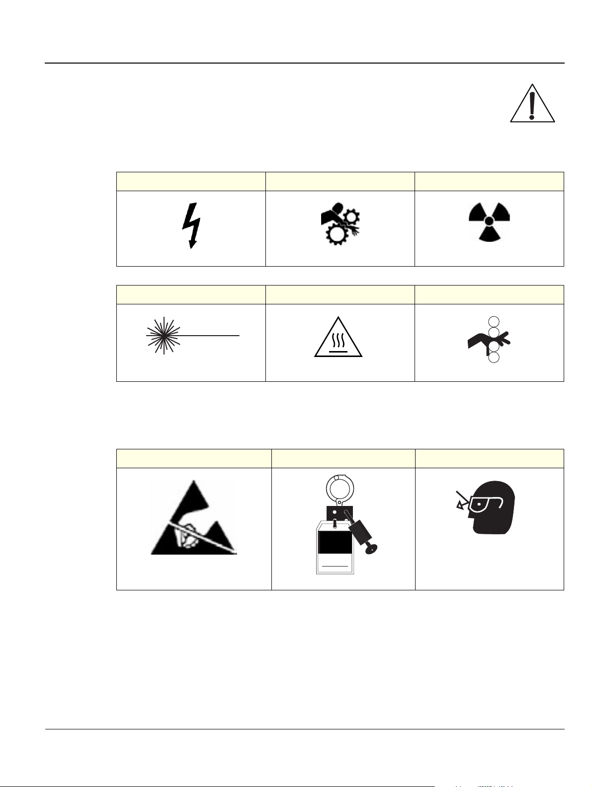
1-2-1-4 Standard Hazard Icons
Important information will always be preceded by the exclamation point contained within
a triangle, as seen throughout this chapter. In addition to text, several different graphical
icons (symbols) may be used to make you aware of specific types of hazards that could
cause harm.
Table 1-5 Standard Hazard Icons
ELECTRICAL MECHANICAL RADIATION
LASER HEAT PINCH
LASER
LASER
LIGHT
LIGHT
Other hazard icons make you aware of specific procedures that should be followed.
Table 1-6 Standard Icons Indicating a Special Procedure Be Used
AVOID STATIC ELECTRICITY TAG AND LOCK OUT WEAR EYE PROTECTION
TAG
TAG
&
&
LOCKOUT
LOCKOUT
Date
Signed
EYE
EYE
PROTECTION
PROTECTION
Chapter 1 - Introduction 1-7
Page 31

GE MEDICAL SYSTEMS
IRECTION 2300164-100, REVISION 7VIVID™ 3 PRO/VIVID™ 3 SERVICE MANUAL
D
Section 1-3 Safety Considerations
1-3-1 Introduction
The following safety precautions must be observed during all phases of operation, service and repair of
this equipment. Failure to comply with these precautions or with specific warnings elsewhere in this
manual, violates safety standards of design, manufacture and intended use of the equipment.
1-3-2 Human Safety
Operating personnel must not remove the system covers.
Servicing should be performed by authorized personnel only.
Only personnel who have participated in Vivid™ 3 Training are authorized to service the equipment.
1-3-3 Mechanical Safety
DANGER: WHEN THE UNIT IS RAISED FOR A REPAIR OR MOVED ALONG ANY INCLINE,
USE EXTREME CAUTION SINCE IT MAY BECOME UNSTABLE AND TIP OVER.
DANGER: ULTRASOUND PROBES ARE HIGHLY SENSITIVE MEDICAL INSTRUMENTS
THAT CAN EASILY BE DAMAGED BY IMPROPER HANDLING. USE CARE WHEN
HANDLING AND PROTECT FROM DAMAGE WHEN NOT IN USE. DO NOT USE A
DAMAGED OR DEFECTIVE PROBE. FAILURE TO FOLLOW THESE PRECAUTIONS CAN
RESULT IN SERIOUS INJURY AND EQUIPMENT DAMAGE.
DANGER: NEVER USE A PROBE THAT HAS BEEN SUBJECTED TO MECHANICAL
SHOCK OR IMPACT. EVEN IF THE PROBE APPEARS TO BE UNBROKEN, IT MAY IN
FACT BE DAMAGED.
CAUTION: Always lower and center the Operator I/O Panel before moving the scanner.
CAUTION: The Vivid™ 3 weighs 160 kg (353 lbs.)or more, depending on installed peripherals,
when ready for use. Care must be used when moving it or replacing its parts. Failure to follow
the precautions listed could result in injury, uncontrolled motion and costly damage.
ALWAYS:
Be sure the pathway is clear.
Use slow, careful motions.
Use two people when moving the system on inclines or lifting more than 16 kg (35 lbs).:
WARNING: Always lock the control console in its parking (locked) position after moving the
system. Failure to do so could result in personal injury or equipment damage.
1-8 Section 1-3 - Safety Considerations
Page 32

GE MEDICAL SYSTEMS
IRECTION 2300164-100, REVISION 7VIVID™ 3 PRO/VIVID™ 3 SERVICE MANUAL
D
WARNING: Equipment damage could result if special care is not taken when transporting the
system in a vehicle.
ALWAYS:
• Secure the system in an upright position and lock the wheels (brake).
• DO NOT use the control console as an anchor point.
• Place the probes in their carrying case.
• Eject any disks from the MOD (if installed).
• Ensure that the system is well prepared and packed in its original packaging before
transporting. Special care must be taken to correctly position the packing material
supporting the monitor. For further information, refer to Chapter 3 - Installation.
CAUTION: Keep the heat venting holes on the monitor unobstructed to avoid overheating of the
monitor.
1-3-4 Electrical Safety
To minimize shock hazard, the equipment chassis must be connected to an electrical Ground. The
system is equipped with a three-conductor AC power cable. This must be plugged into an approved
electrical outlet with safety grounding.
The power outlet used for this equipment should not be shared with other types of equipment. Both the
system power cable and the power connector must meet international electrical standards.
1-3-4-1 Probes
All the probes for the Vivid™ 3 ultrasound unit are designed and manufactured to provide trouble-free,
reliable service. To ensure this, correct handling of probes is important and the following points should
be noted:
• Do not drop a probe or strike it against a hard surface, as this may damage the transducer elements,
acoustic lens, or housing.
• Do not use a cracked or damaged probe. In this event, call your field service representative
immediately to obtain a replacement.
• Avoid pulling, pinching or kinking the probe cable, since a damaged cable may compromise the
electrical safety of the probe.
• To avoid the risk of a probe accidentally falling, do not allow the probe cables to become entangled,
or to be caught in the machine’s wheels.
NOTE: For detailed information on handling endocavity probes, refer to the appropriate supplementary
instructions for each probe. In addition, refer to the Vivid™ 3 Pro/Vivid™ 3 Expert User Manual for
detailed probe handling instructions.
Chapter 1 - Introduction 1-9
Page 33

GE MEDICAL SYSTEMS
IRECTION 2300164-100, REVISION 7VIVID™ 3 PRO/VIVID™ 3 SERVICE MANUAL
D
1-3-5 Dangerous Procedure Warnings
Warnings, such as the examples below, precede potentially dangerous procedures throughout this
manual. Instructions contained in the warnings must be followed.
DANGEROUS VOLTAGES, CAPABLE OF CAUSING DEATH, ARE PRESENT IN THIS
EQUIPMENT. USE EXTREME CAUTION WHEN HANDLING, TESTING AND ADJUSTING.
EXPLOSION WARNING
DO NOT OPERATE THE EQUIPMENT IN AN EXPLOSIVE ATMOSPHERE.
OPERATION OF ANY ELECTRICAL EQUIPMENT IN SUCH AN ENVIRONMENT CONSTITUTES A
DEFINITE SAFETY HAZARD.
DO NOT SUBSTITUTE PARTS OR MODIFY EQUIPMENT
BECAUSE OF THE DANGER OF INTRODUCING ADDITIONAL HAZARDS, DO NOT INSTALL
SUBSTITUTE PARTS OR PERFORM ANY UNAUTHORIZED MODIFICATION OF THE
EQUIPMENT.
1-10 Section 1-3 - Safety Considerations
Page 34

GE MEDICAL SYSTEMS
IRECTION 2300164-100, REVISION 7VIVID™ 3 PRO/VIVID™ 3 SERVICE MANUAL
D
Section 1-4 Product Labels and Icons
The Vivid™ 3 ultrasound unit comes equipped with product labels and icons. These labels and icons
represent pertinent information regarding the operation of the ultrasound unit.
1-4-1 Product Label Locations
The following two diagrams indicate the location of some of the labels and icons found on the Vivid™ 3
ultrasound units. All the labels and icons are described in Table 1-7 on page 1-13.
1
2
3
Figure 1-1 Product Label and Icon Locations (Front)
1 Product Logo
2 Equipment Type CF
3 Parking Label on Brake Pedal
4 Class II Equipment
5 Swivel Brake Label on Brake Pedal
Chapter 1 - Introduction 1-11
4
5
Page 35

GE MEDICAL SYSTEMS
IRECTION 2300164-100, REVISION 7VIVID™ 3 PRO/VIVID™ 3 SERVICE MANUAL
D
3
Figure 1-2 Product Label and Icon Locations (Rear)
1 Main Label
2 AC Voltage Rating Label
3 GND Label
1
2
1-12 Section 1-4 - Product Labels and Icons
Page 36

GE MEDICAL SYSTEMS
IRECTION 2300164-100, REVISION 7VIVID™ 3 PRO/VIVID™ 3 SERVICE MANUAL
D
1-4-2 Label Descriptions
The following table shows the labels and symbols that may be found on the Vivid™ 3 ultrasound unit,
and provides a description of each label’s purpose and location.
Table 1-7 Product Icons
Label Name Description Location
Product Logo Identifies Vivid™ 3 models. Front of the unit.
Manufacturer’s name and address.
Identification and Rating
Plate
Date of Manufacture.
Model and Serial numbers.
Electrical ratings.
Class I Equipment, in which protection
against electric shock does not rely on basic
insulation only, but which includes an
additional safety precaution in that means
are provided for the connection of the
equipment to the protective earth conductor
in the fixed wiring of the installation - in such
a way that accessible metal parts cannot
become live in the event of a failure of the
basic insulation.
Rear of the unit, near the power inlet.
Rear of the unit and probe
connectors.
Device Listing/Certification
Labels
CAUTION - This machine
weighs...Special care must
be used to avoid..."
Laboratory logos or labels that denote
conformity with industry safety standards,
such as UL or IEC.
CE certification mark. Rear of the unit, on the main label.
Equipment Type BF (man in the box symbol)
IEC 878-02-03 indicates B Type equipment
having even more electrical isolation than
standard Type B equipment because it is
intended for intimate patient contact.
Equipment Type CF IEC 878-02-05
indicates equipment having a floating
applied part that provides a degree of
protection suitable for direct cardiac contact.
This precaution is intended to prevent injury
that may be caused by the weight of the
machine if one person attempts to move it
considerable distances or on an incline.
Rear of the unit.
Probe connectors
PCG connector
or Rear of Console
Front of the unit, ECG connector and
surgical probes.
Used in the Service and User Manual
which should be adjacent to
equipment at all times for quick
reference.
Chapter 1 - Introduction 1-13
Page 37

GE MEDICAL SYSTEMS
IRECTION 2300164-100, REVISION 7VIVID™ 3 PRO/VIVID™ 3 SERVICE MANUAL
D
Table 1-7 Product Icons (Continued)
Label Name Description Location
"DANGER - Risk of explosion
used in..."
The system is not designed for use with
flammable anesthetic gases.
"CAUTION" The equilateral triangle is
usually used in combination with other
symbols to advise or warn the user.
“ATTENTION - Consult accompanying
documents” is intended to alert the user to
refer to the User Manual or other instructions
when complete information cannot be
provided on the label.
"CAUTION - Dangerous voltage" (the
lightning flash with arrowhead in equilateral
triangle) is used to indicate electric shock
hazards.
"Protective Earth" Indicates the protective
earth (grounding) terminal.
Indicated in the Service Manual.
Rear of the unit.
Rear of the unit.
Rear of the unit.
Rear of the unit.
"Equipotentiality" Indicates the terminal to be
used for connecting equipotential
conductors when interconnecting
(grounding) with other equipment.
Waste Electrical and Electronic Equipment
(WEEE) Disposal
This symbol indicates that the waste of
electrical and electronic equipment must not
be disposed as unsorted municipal waste
and must be collected separately.
Please contact an authorized representative
of the manufacturer for information
concerning the decommissioning of your
equipment.
Peripherals
Rear of the unit.
1-14 Section 1-4 - Product Labels and Icons
Page 38

GE MEDICAL SYSTEMS
IRECTION 2300164-100, REVISION 7VIVID™ 3 PRO/VIVID™ 3 SERVICE MANUAL
D
1-4-3 Vivid™ 3 External Labels
In addition to the labels described in the previous section, additional labels may be found on the
Vivid™ 3 ultrasound unit, as described in the following sections:
• Main Label section, on page 1-15.
• Rating Labels section, on page 1-23.
• GND Label section, on page 1-24.
• Parking Label section, on page 1-24.
• Swivel Brake Label section, on page 1-24.
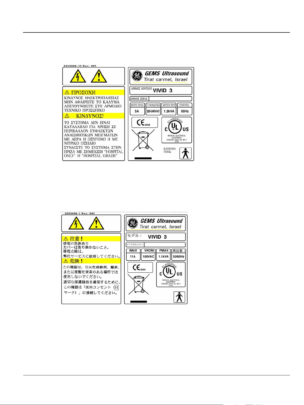
1-4-3-1 Main Label
The main label may be printed in any of the following languages: English, German, French, Spanish,
Portuguese, Italian, Chinese, Danish, Dutch, Finnish, Greek, Japanese, Norwegian, Russian, or
Swedish, as shown in the examples below. Each main label includes a serial number, a voltage rating,
caution warnings, danger warnings and classifications (UL, CE0344 and so on.)
• English: Used for all countries except those in which German, French, Spanish, Portuguese or
Italian are spoken.
Figure 1-3 Main Label (English) 220 -240V
.
Figure 1-4 Main Label (English) USA
Chapter 1 - Introduction 1-15
Page 39

GE MEDICAL SYSTEMS
IRECTION 2300164-100, REVISION 7VIVID™ 3 PRO/VIVID™ 3 SERVICE MANUAL
D
• German: Used in all German language countries.
Figure 1-5 Main Label (German)
• French: Used in all French language countries.
Figure 1-6 Main Label (French)
1-16 Section 1-4 - Product Labels and Icons
Page 40

GE MEDICAL SYSTEMS
IRECTION 2300164-100, REVISION 7VIVID™ 3 PRO/VIVID™ 3 SERVICE MANUAL
D
• Spanish: Used in all Spanish language countries.
Figure 1-7 Main Label (Spanish)
• Portuguese: Used in all Portuguese language countries.
Figure 1-8 Main Label (Portuguese)
Chapter 1 - Introduction 1-17
Page 41

GE MEDICAL SYSTEMS
IRECTION 2300164-100, REVISION 7VIVID™ 3 PRO/VIVID™ 3 SERVICE MANUAL
D
Figure 1-9 Main Label (Portuguese) 220 - 240V
• Italian: Used in all Italian language countries.
Figure 1-10 Main Label (Italian)
1-18 Section 1-4 - Product Labels and Icons
Page 42

GE MEDICAL SYSTEMS
IRECTION 2300164-100, REVISION 7VIVID™ 3 PRO/VIVID™ 3 SERVICE MANUAL
D
• Chinese: Used in all Chinese language countries.
Figure 1-11 Main Label (Chinese)
• Danish: Used in all Danish language countries.
Figure 1-12 Main Label (Danish)
Chapter 1 - Introduction 1-19
Page 43

GE MEDICAL SYSTEMS
IRECTION 2300164-100, REVISION 7VIVID™ 3 PRO/VIVID™ 3 SERVICE MANUAL
D
• Dutch: Used in all Dutch language countries.
Figure 1-13 Main Label (Dutch)
• Finnish: Used in all Finnish language countries.
Figure 1-14 Main Label (Finnish)
1-20 Section 1-4 - Product Labels and Icons
Page 44
GE MEDICAL SYSTEMS
IRECTION 2300164-100, REVISION 7VIVID™ 3 PRO/VIVID™ 3 SERVICE MANUAL
D
• Greek: Used in all Greek language countries.
Figure 1-15 Main Label (Greek)
• Japanese: Used in all Japanese language countries.
Figure 1-16 Main Label (Japanese)
Chapter 1 - Introduction 1-21
Page 45

GE MEDICAL SYSTEMS
IRECTION 2300164-100, REVISION 7VIVID™ 3 PRO/VIVID™ 3 SERVICE MANUAL
D
• Norwegian: Used in all Norwegian language countries.
Figure 1-17 Main Label (Norwegian)
• Russian: Used in all Russian language countries.
Figure 1-18 Main Label (Russian)
1-22 Section 1-4 - Product Labels and Icons
Page 46

GE MEDICAL SYSTEMS
IRECTION 2300164-100, REVISION 7VIVID™ 3 PRO/VIVID™ 3 SERVICE MANUAL
D
• Swedish: Used in all Swedish language countries.
Figure 1-19 Main Label (Swedish)
1-4-3-2 Rating Labels
Indicates the ultrasound unit’s factory preset input AC voltage as follows:
• AC 100V
• AC 120V
• AC 220-240V
One of the rating labels shown below is located on the rear of the ultrasound unit, as shown in
Figure 1-2 on page 1-12.
Figure 1-20 Rating Labels
Chapter 1 - Introduction 1-23
Page 47

GE MEDICAL SYSTEMS
IRECTION 2300164-100, REVISION 7VIVID™ 3 PRO/VIVID™ 3 SERVICE MANUAL
D
1-4-3-3 GND Label
Indicates the protective earth (grounding) terminal. The GND label shown below is located at the rear
of the unit, as shown in Figure 1-2 on page 1-12.
Figure 1-21 GND Label
1-4-3-4 Parking Label
Indicates the locked pedal position which locks the front castors and prevents the ultrasound unit from
moving. The parking label, shown below, is located on the brake pedal at the front of the unit, as shown
in Figure 1-1 on page 1-11.
Figure 1-22 Parking Label
1-4-3-5 Swivel Brake Label
Indicates the locked swivel position which prevents the front castors from swiveling. The swivel brake
label, shown below, is located on the brake pedal at the front of the unit, as shown in Figure 1-1 on
page 1-11.
Figure 1-23 Swivel Break Label
1-24 Section 1-4 - Product Labels and Icons
Page 48

GE MEDICAL SYSTEMS
IRECTION 2300164-100, REVISION 7VIVID™ 3 PRO/VIVID™ 3 SERVICE MANUAL
D
Section 1-5 EMC, EMI, and ESD
1-5-1 Electromagnetic Compatibility (EMC)
Electromagnetic compatibility describes a level of performance of a device within its electromagnetic
environment. This environment consists of the device itself and its surroundings, including other
equipment, power sources and persons with which the device must interface. Inadequate compatibility
results when a susceptible device fails to perform as intended due to interference from its environment,
or when the device produces unacceptable levels of emission. This interference is often referred to as
radio–frequency or electromagnetic interference (RFI/EMI) and can be radiated through space or
conducted over interconnecting power or signal cables. In addition to electromagnetic energy, EMC
also includes possible effects from electrical fields, magnetic fields, electrostatic discharge and
disturbances in the electrical power supply.
1-5-2 Electrostatic Discharge (ESD) Prevention
CAUTION: DO NOT TOUCH ANY BOARDS WITH INTEGRATED CIRCUITS PRIOR TO
TAKING THE NECESSARY ESD PRECAUTIONS:
1.ALWAYS CONNECT YOURSELF, VIA AN ARM-WRIST STRAP, TO THE ADVISED ESD
CONNECTION POINT LOCATED ON THE REAR OF THE SCANNER (TO THE RIGHT OF
THE POWER CONNECTOR).
2.FOLLOW GENERAL GUIDELINES FOR HANDLING OF ELECTROSTATIC SENSITIVE
EQUIPMENT.
Chapter 1 - Introduction 1-25
Page 49

GE MEDICAL SYSTEMS
IRECTION 2300164-100, REVISION 7VIVID™ 3 PRO/VIVID™ 3 SERVICE MANUAL
D
1-5-3 Standards Used
To fulfill the requirements of relevant EC directives and/or European Harmonized/International
standards, the following documents/standards have been used:
Table 1-8 Standards Used
Standard/Directive Scope
89/336/EEC EMC Directive.
93/42/EEC Medical Device Directive.
IEC 801-2 Electrostatic Discharge.
IEC 801-3 Radiated Electromagnetic Field.
IEC 801-4 Electrical Fast Transient/Burst.
IEC 805-1 Surge.
EN 55011/CISPR 11 Electromagnetic Susceptibility.
EN 60601-1/IEC 601-1/UL 2601-1 Medical Electrical Equipment; General Requirements for Safety.
EN 61157/ IEC 61157
Requirements for the declaration of the acoustic output of medical
diagnostic ultrasonic equipment.
NOTE: For CE Compliance, it is critical that all covers, screws, shielding, gaskets, mesh and clamps are in good
condition and installed tightly without skew or stress. Proper installation following all comments noted
in this service manual is required in order to achieve full EMC performance.
1-5-4 Lockout/Tagout Requirements (For USA Only)
Follow OSHA Lockout/Tagout requirements by ensuring you are in total control of the electrical Mains
plug.
1-26 Section 1-5 - EMC, EMI, and ESD
Page 50

GE MEDICAL SYSTEMS
IRECTION 2300164-100, REVISION 7VIVID™ 3 PRO/VIVID™ 3 SERVICE MANUAL
D
Section 1-6 Customer Assistance
1-6-1 Contact Information
If this equipment does not work as indicated in this service manual or in the Vivid™ 3 Pro/Vivid™ 3
Expert User Manual, or if you require additional assistance, please contact the local distributor or
appropriate support resource, as listed below.
Prepare the following information before you call:
• System ID and/or serial number.
• Software version.
Table 1-9 GE Contact Information
Location Phone Number
USA/ Canada
GE Medical Systems
Ultrasound Service Engineering
4855 W. Electric Avenue
Milwaukee, WI 53219
Customer Answer Center
Latin America
GE Medical Systems
Ultrasound Service Engineering
4855 W. Electric Avenue
Milwaukee, WI 53219
Customer Answer Center
Europe
GE Ultraschall Deutschland GmbH& Co. KG
BeethovenstraBe 239
Postfach 11 05 60, D-42665 Solingen
Germany
Asia (Singapore/ Japan)
GE Ultrasound Asia
Service Department - Ultrasound
298 Tiong Bahru Road #15-01/06
Central Plaza
Singapore 169730
Phone: +1-800-437-1171
Phone: +1-800-321-7937
Phone: +1-800-682-5327
Phone: +1-262-524-5698
Fax: +1-414-647-4125
Phone: +1-262-524-5300
Phone: +1-262-524-5698
Fax: +1-414-647-4125
General Imaging: +49 (212) 2802 207
Cardiac: +49 (212) 2802 208
Fax: +49 212 2802 431
Phone: +65-277-3487
Fax: +65-272-3997
Phone: +81-426-48-2950
Fax: +81-426-48-2902
Chapter 1 - Introduction 1-27
Page 51

GE MEDICAL SYSTEMS
IRECTION 2300164-100, REVISION 7VIVID™ 3 PRO/VIVID™ 3 SERVICE MANUAL
D
Chapter 2 Pre-Installation
Section 2-1 Overview
2-1-1 Purpose of Chapter 2
This chapter provides the information required to plan and prepare for the installation of a Vivid™ 3
ultrasound unit. Included are descriptions of the electrical and facility requirements that must be met by
the purchaser. A worksheet is provided at the end of this chapter (see Figure 2-2 on page 2-11) to help
ensure that all the required network information is available, prior to installation.
Table 2-1 Contents in Chapter 2
Section Description Page Number
2-1
2-2
2-3
Overview
Console Requirements
Facility Needs
2-1
2-2
2-7
Chapter 2 - Pre-Installation 2-1
Page 52

GE MEDICAL SYSTEMS
IRECTION 2300164-100, REVISION 7VIVID™ 3 PRO/VIVID™ 3 SERVICE MANUAL
D
Section 2-2 Console Requirements
2-2-1 Unit Environmental Requirements
Table 2-2 Environmental Requirements
Relative Humidity
Requirement Temperature
(non-condensing)
Air Pressure
Operational
Storage
Transport
10 — 40
-20 — 60
-20 — 60
o
C (50 — 104oF)
o
C (-4 — 140oF)
o
C (-4 — 140oF)
50 — 70% 700 — 1060 hPa
10 — 95% 700 — 1060 hPa
10 — 95% 700— 1060 hPa
CAUTION: If the system has been in storage or has been transported, please see the acclimation
requirements before powering
ON and/or using the system. Refer to the Installation Warnings section
on page 3-2.
2-2-2 Cooling Requirements
The cooling requirement for the Vivid™ 3 ultrasound unit environment is
3500 BTU/hr. This figure does not include the cooling required for lights, people, or other equipment in
the room.
Note: Each person in the room places an additional 300 BTU/hr demand on the environmental cooling.
2-2-3 Lighting Requirements
For system installation, updates and repairs, bright lighting is required. However, operator and patient
comfort may be optimized if the room lighting is subdued and indirect when a scan is being performed.
Therefore, a combination lighting system (dim/bright) is recommended. Keep in mind that lighting
controls and dimmers can be a source of EMI which could degrade image quality. These controls should
be selected to minimize possible interference.
2-2-4 Time and Manpower Requirements
Site preparation takes time. Begin pre-installation checks as soon as possible to allow sufficient time to
make any required changes. If possible, begin these checks as many as six weeks before system
delivery.
CAUTION: At least two people must be available to deliver and unpack the Vivid™ 3 ultrasound
unit. Attempts to move the unit considerable distances (or on an incline) by one person alone,
could result in personal injury, and/or damage to the system.
2-2 Section 2-2 - Console Requirements
Page 53

GE MEDICAL SYSTEMS
IRECTION 2300164-100, REVISION 7VIVID™ 3 PRO/VIVID™ 3 SERVICE MANUAL
D
2-2-5 Electrical Requirements
NOTE: GE Medical Systems requires a dedicated power and Ground for the proper operation of its
Ultrasound equipment. This dedicated power shall originate at the last distribution panel before
the system.
Sites with a mains power system with defined Neutral and Live:
The dedicated line shall consist of one phase, a neutral (not shared with any other circuit), and a full
size Ground wire from the distribution panel to the Ultrasound outlet.
Sites with a mains power system without a defined Neutral:
The dedicated line shall consist of one phase (two lines), not shared with any other circuit, and a full
size Ground wire from the distribution panel to the Ultrasound outlet.
NOTE: Please note that image artifacts can occur, if at any time within the facility, the Ground from the
main facility's incoming power source to the Ultrasound unit is only a conduit.
2-2-5-1 Vivid™ 3 Power Requirements
Electrical specifications for the Vivid™ 3 monitor and onboard peripherals are as follows:
Table 2-3 Electrical Requirements
Voltage Tolerances Op. Current Frequency
100V AC ±10% 8A 50-60 Hz
120V AC ±10% 8A 50-60 Hz
220 - 240V AC ±10% 4A 50-60 Hz
2-2-5-2 Inrush Current
Inrush current is not a factor for consideration, due to the inrush current limiting properties of the power
supplies.
Maximum power requirement = 1.2 KVa
• 100V AC: 8A
• 120V AC: 8A
• 220 - 240V AC: 4A
2-2-5-3 Site Circuit Breaker
It is recommended that the branch circuit breaker for the machine be readily accessible.
CAUTION
POWER OUTAGE MAY OCCUR.
The Vivid 3 requires a dedicated single branch circuit. To avoid circuit overload and possible
loss of critical care equipment, make sure you DO NOT have any other equipment operating on
the same circuit.
Chapter 2 - Pre-Installation 2-3
Page 54

GE MEDICAL SYSTEMS
IRECTION 2300164-100, REVISION 7VIVID™ 3 PRO/VIVID™ 3 SERVICE MANUAL
D
2-2-5-4 Site Power Outlets
A dedicated AC power outlet must be within reach of the unit without requiring the use of extension
cords. Other outlets adequate for the external peripherals, medical and test equipment required to
support this unit must also be present and located within 1 m (3.2 ft) of the unit. Electrical installation
must meet all current local, state, and national electrical codes.
2-2-5-5 Mains Power Plug
If the unit arrives without a power plug, or with the wrong plug, contact your GE dealer. When necessary,
the installation engineer will supply the locally-required power plug.
2-2-5-6 Power Stability Requirements
Voltage drop-out
Max 10 ms.
NOTE: The Vivid™ 3 ultrasound unit can be provided with an external UPS system. Contact your local GE
Service Representative for details.
Power Transients
(All applications)
Less than 25% of nominal peak voltage for less than 1 millisecond for any type of transient, including
line frequency, synchronous, asynchronous, or aperiodic transients.
2-4 Section 2-2 - Console Requirements
Page 55

GE MEDICAL SYSTEMS
IRECTION 2300164-100, REVISION 7VIVID™ 3 PRO/VIVID™ 3 SERVICE MANUAL
D
2-2-6 EMI Limitations
Ultrasound machines are susceptible to Electromagnetic Interference (EMI) from radio frequencies,
magnetic fields, and transients in the air or wiring. They also generate EMI. The Vivid™ 3 ultrasound
unit complies with limits as stated on the EMC label. However, there is no guarantee that interference
will not occur in a particular installation.
Note: Possible EMI sources should be identified before the unit is installed, and should not be on the
same line as the ultrasound system. A dedicated line should be used for the ultrasound system.
Electrical and electronic equipment may produce EMI unintentionally as the result of a defect. Sources
of EMI include the following:
• Medical lasers.
• Scanners.
• Cauterizing guns.
•Computers.
•Monitors.
•Fans.
• Gel warmers.
• Microwave ovens.
• Portable phones.
• Broadcast stations and mobile broadcasting machines.
Chapter 2 - Pre-Installation 2-5
Page 56

GE MEDICAL SYSTEMS
IRECTION 2300164-100, REVISION 7VIVID™ 3 PRO/VIVID™ 3 SERVICE MANUAL
D
The following table lists recommendations for preventing EMI:
Table 2-4 EMI Prevention/ Abatement
EMI Rule Details
Ground the unit.
Be aware of RF sources.
Replace and/or reassemble
all screws, RF gaskets,
covers and cores.
Replace broken RF gaskets.
Do not place labels where
RF gaskets touch metal.
Use GE specified harnesses
and peripherals.
Take care with cellular
phones.
Properly address peripheral
cables.
Poor grounding is the most likely reason an ultrasound unit will have noisy images.
Check the grounding of the power cord and power outlet.
Keep the unit at least 5m (16.4 ft) away from other EMI sources. Special shielding may
be required to eliminate interference problems caused by high frequency, high powered
radio or video broadcast signals.
After you finish repairing or updating the system, replace all covers and tighten all
screws. Any cable with an external connection requires a magnet wrap at each end.
Install the shield over the front of the card cage. Loose or missing covers or RF gaskets
allow radio frequencies to interfere with the ultrasound signals.
If more than 20% or a pair of the fingers on an RF gasket are broken, replace the gasket.
Do not turn ON the unit until any loose metallic part is removed and replaced, if required.
Never place a label where RF gaskets meet the unit. Otherwise, the gap created will
permit RF leakage. In case a label has been found in such a location, move the label to
a different, appropriate location.
The interconnect cables are grounded and require ferrite beads and other shielding.
Cable length, material, and routing are all important; do not make any changes that do
not meet all specifications.
Cellular phones may transmit a 5 V/m signal that causes image artifacts.
Do not allow cables to lie across the top of the card cage or hang out of the peripheral
bays. Loop any peripheral cable excess length inside the peripheral bays or hang on the
hooks provided below the console. Attach the monitor cables to the frame.
2-2-7 Probe Environmental Requirements
Table 2-5 Probe Operation and Storage Temperatures
Electronics PAMPTE
Operation
Storage
Note: System and electronic probes are designed for storage temperatures of -20o to +50o C. When
exposed to large temperature variations, the probes should be kept at room temperature for
a minimum of 10 hours before use.
10 — 40oC (50 — 104oF) 5 — 42.7oC (41 — 109oF)
-20 — 50oC (-4 — 122oF) -20 — 50oC (-4 — 122oF)
2-6 Section 2-2 - Console Requirements
Page 57

GE MEDICAL SYSTEMS
IRECTION 2300164-100, REVISION 7VIVID™ 3 PRO/VIVID™ 3 SERVICE MANUAL
D
Section 2-3 Facility Needs
2-3-1 Purchaser Responsibilities
The work and materials required to prepare the site are the responsibility of the purchaser. To avoid
delay, complete all pre-installation work before delivery. Use the Pre-installation Check List (provided
in Table 2-6 on page 2-12) to verify that all the required steps have been completed.
Purchaser responsibilities include:
• Procuring the required materials.
• Completing the preparations prior to delivery of the ultrasound system.
• Paying the costs of any alterations and modifications not specifically provided for in the sales
contract.
Note: All relevant preliminary electrical installations at the prepared site must be performed by
licensed electrical contractors. Other connections between electrical equipment, and
calibration and testing, must also be performed by qualified personnel. The products involved
(and the accompanying electrical installations) are highly sophisticated and special engineering
competence is required. All electrical work on these products must comply with the
requirements of applicable electrical codes. The purchaser of GE equipment must utilize only
qualified personnel to perform electrical servicing of the equipment.
To avoid delays during installation, the individual or team who will perform the installation should be
notified at the earliest possible date (preferably prior to installation), of the existence of any of the
following variances:
• Use of any non-listed product(s).
• Use of any customer provided product(s).
• Placement of an approved product further from the system than the interface kit allows.
The prepared site must be clean prior to delivery of the system. Carpeting is not recommended because
it collects dust and creates static. Potential sources of EMI should also be investigated before delivery.
Dirt, static, and EMI can negatively impact system reliability.
Chapter 2 - Pre-Installation 2-7
Page 58

GE MEDICAL SYSTEMS
IRECTION 2300164-100, REVISION 7VIVID™ 3 PRO/VIVID™ 3 SERVICE MANUAL
D
2-3-2 Mandatory Site Requirements
The following are mandatory site requirements. Additional (optional) recommendations, as well as a
recommended ultrasound room layout, are provided in section 2-3-3 - Site Recommendations (see
below).
• A dedicated single branch power outlet of adequate amperage (see Table 2-3 on page 2-3.) that
meets all local and national codes and is located less than 2.5 m (8.2 ft) from the unit’s proposed
location. Refer to the Electrical Requirements section on page 2-3.
• A door opening of at least 76 cm (2.5 ft) in width.
• The proposed location for the unit is at least 0.3 m (1 ft) from the walls, to enable cooling.
• Power outlets for other medical equipment and gel warmer.
• Power outlets for test equipment within 1 m (3.3 ft) of the ultrasound unit.
• Clean and protected space for storage of probes (either in their case or on a rack).
• Material to safely clean probes.
• In the case of a network option:
• An active network outlet in the vicinity of the ultrasound unit.
• A network cable of appropriate length (regular Pin-to-Pin network cable).
• An IT administrator who will assist in configuring the unit to work with your local network. A fixed
IP address is required. Refer to the form provided in Figure 2-2 on page 2-11 for network details
that are required.
Note: All relevant preliminary network outlets installations at the prepared site must be performed by
authorized contractors. The purchaser of GE equipment must utilize only qualified personnel to
perform servicing of the equipment.
2-3-3 Site Recommendations
The following are (optional) site recommendations. Mandatory site requirements are provided in the
Mandatory Site Requirements section, above.
• A door opening of 92 cm (3 ft) in width.
• An accessible circuit breaker for a dedicated power outlet.
• A sink with hot and cold running water.
• A receptacle for bio–hazardous waste, for example, used probe sheaths.
• An emergency oxygen supply.
• A storage area for linens and equipment.
• A nearby waiting room, lavatory, and dressing room.
• Dual level lighting (bright and dim).
• A lockable cabinet for software and manuals.
2-8 Section 2-3 - Facility Needs
Page 59

GE MEDICAL SYSTEMS
IRECTION 2300164-100, REVISION 7VIVID™ 3 PRO/VIVID™ 3 SERVICE MANUAL
D
2-3-3-1 Recommended Ultrasound Room Layout
VIVID 3
36 IN.
(92 CM)
Scale: Each square = 1 sq ft (144 sq ins)
Figure 2-1 Minimal Floor Plan 2.5m x 3m (8.2ft x 9.84 ft)
2-3-4 Networking Pre-Installation Requirements
2-3-4-1 Stand-alone Unit (without Network Connection)
None.
2-3-4-2 Unit Connected to Hospital’s Network
Supported networks:
Dedicated Power Outlets
Hospital Network
Dedicated Analog Telephone Line
for Connection to InSite
GE Cabinet for
Software and Manuals
(optional)
• 100/10 Mbit/sec
2-3-4-3 Purpose of the DICOM Network Function
DICOM services provide the operator with clinically useful features for moving images and patient
information over a hospital network. Examples of DICOM services include the transfer of images to
workstations for viewing or transferring images to remote printers. As an added benefit, transferring
images in this manner frees up the on-board monitor and peripherals, enabling viewing to be done while
scanning continues. With DICOM, images can be archived, stored, and retrieved faster, easier, and at
a lower cost.
Chapter 2 - Pre-Installation 2-9
Page 60

GE MEDICAL SYSTEMS
IRECTION 2300164-100, REVISION 7VIVID™ 3 PRO/VIVID™ 3 SERVICE MANUAL
D
2-3-4-4 DICOM Option Pre-Installation Requirements
To configure the Vivid™ 3 ultrasound unit to work with other network connections, the network
administrator must provide the required information, which should include the following:
• Vivid™ 3 Details: DICOM network details for the Vivid™ 3 unit, including the host name, local port,
IP address, AE title and net mask.
• Routing Information: IP addresses for the default gateway and other routers in use at the site.
• DICOM Application Information: Details of the DICOM devices in use at the site, including the
DICOM host name, AE title and IP addresses.
2-10 Section 2-3 - Facility Needs
Page 61
GE MEDICAL SYSTEMS
IRECTION 2300164-100, REVISION 7VIVID™ 3 PRO/VIVID™ 3 SERVICE MANUAL
D
Section 2-4 Connectivity Installation Worksheet
Site System Information
Site:
Dept:
Vivid™ 3 SN:
CONTACT INFORMATION
Name
TCP/IP Settings
Scanner IP Settings
Name - AE Title:
IP Address:
Subnet Mask:
Default Gateway:
Type:
Title
Floor:
Room:
REV:
Phone
Comments:
E-Mail Address
Remote Archive Setup
(Echo Server/GEMNet Server/EchoPac PC)
Name - AE Title:
IP Address:
Subnet Mask:
Default Gateway:
Server Name:
Remote DB User Name:
Services (Destination Devices)
Device Type
1
2
3
4
5
6
7
8
9
10
11
12
Manufacturer
Figure 2-2 Connectivity Installation Worksheet
Name
IP Address
Port
AE Title
Chapter 2 - Pre-Installation 2-11
Page 62

GE MEDICAL SYSTEMS
IRECTION 2300164-100, REVISION 7VIVID™ 3 PRO/VIVID™ 3 SERVICE MANUAL
D
Table 2-6 Pre-Installation Check List
Action Yes No
Schedule at least 3 hours for installation of the system.
Notify installation team of the existence of any variances from the basic installation.
Make sure system and probes have been subject to acclimation period.
Environmental cooling is sufficient.
Lighting is adjustable to adapt to varying operational conditions of the scanner.
Electrical facilities meet system requirements.
EMI precautions have been taken and all possible sources of interference have been
removed.
Mandatory site requirements have been met.
If a network is used, IP address has been set for the system and a dedicated network
outlet is available.
2-12 Section 2-4 - Connectivity Installation Worksheet
Page 63

GE MEDICAL SYSTEMS
IRECTION 2300164-100, REVISION 7VIVID™ 3 PRO/VIVID™ 3 SERVICE MANUAL
D
Chapter 3 Installation
Section 3-1 Overview
3-1-1 Purpose of Chapter 3
This chapter provides instructions for installing the Vivid™ 3 ultrasound unit. Before beginning the
installation process, an appropriate site must be prepared, as described in Chapter 2 - Pre-Installation.
Once the site has been prepared, installation can proceed as described in this chapter.
Table 3-1 Contents in Chapter 3
Section Description Page Number
3-1
3-2
3-3
3-4
3-5
3-6
3-7
3-8
3-9
Overview
Installation Reminders
Receiving and Unpacking the Equipment
Preparing for Installation
Completing the Hardware Installation
System Configuration
Connectivity Setup
Storing and Transporting the Unit
Completing the Installation Paperwork
3-1
3-2
3-4
3-13
3-22
3-35
3-50
3-68
3-76
Chapter 3 - Installation 3-1
Page 64

GE MEDICAL SYSTEMS
IRECTION 2300164-100, REVISION 7VIVID™ 3 PRO/VIVID™ 3 SERVICE MANUAL
D
Section 3-2 Installation Reminders
3-2-1 Average Installation Time
Once the site has been prepared, the average installation time required is shown in Ta bl e 3 -2 below.
Table 3-2 Average Installation Time
Average
Description
Unpacking the scanner 0.5 hour
Installing the scanner 0.5 hour Time may vary, according to the required configuration
DICOM Option
(connectivity)
3-2-2 Installation Warnings
1.) Since the Vivid™ 3 weighs 160 kg (353 lbs) or more, without options, two persons are always
required to unpack it. This is also applicable when installing any additional items in excess of 16 kg
(35 lbs).
2.) There are no operator-serviceable components. To prevent shock, do not remove any covers or
panels. Should problems or malfunctions occur, unplug the power cord. Only qualified service
personnel should carry out servicing and troubleshooting.
Installation Time
0.5 - 2.0 hours Time may vary, according to the required configuration
Comments
3-2-2-1 System Acclimation Time
Following transport, the Vivid™ 3 system may be very cold, or hot. Allow time for the system to acclimate
o
C increment, when the temperature of
CAUTION
before being switched ON. Acclimation requires 1 hour for each 2.5
o
the system is below 10
C or above 35oC.
Turning the system ON after arrival at the site - without allowing time for acclimation - may
cause system damage!
Table 3-3 Vivid™ 3 System Acclimation Time
60 55 50 45 40 35 30 25 20 15 10 5 0 -5 -10 -15 -20 -25 -30 -35 -40
°C
140 131 122 113 104 96 86 77 68 59 50 41 32 23 14 5 -4 -13 -22 -31 -40
°F
864200000002468101214161820
Hrs
3-2 Section 3-2 - Installation Reminders
Page 65

GE MEDICAL SYSTEMS
IRECTION 2300164-100, REVISION 7VIVID™ 3 PRO/VIVID™ 3 SERVICE MANUAL
D
3-2-3 Safety Reminders
DANGER: WHEN USING ANY TEST INSTRUMENT THAT IS CAPABLE OF
OPENING THE AC GROUND LINE (I.E., METER’S GROUND SWITCH IS OPEN),
DO NOT TOUCH THE UNIT!
WARNING: Two people are required to unpack the unit, as it is heavy. Two people are also
required whenever a part weighing 19kg (35 lb.) or more must be lifted.
CAUTION: If the unit is very cold or hot, do NOT turn ON power to the unit until it has had
sufficient time to acclimate to its operating environment.
CAUTION: To prevent electrical shock, connect the unit to a properly grounded power outlet.
Do NOT use a three-prong to two-prong adapter, as this defeats safety grounding.
CAUTION: Do NOT wear the ESD wrist strap when you work on live circuits where more than
30 V peak is present.
CAUTION: Do NOT operate the unit unless all board covers and frame panels are securely in
place, to ensure optimal system performance and cooling.
When covers are removed, EMI may be present.
WARNING: ACOUSTIC OUTPUT HAZARD
Although the ultrasound energy transmitted from the Vivid™ 3 ultrasound unit is within
AIUM/NEMA standards and FDA limitations, avoid unnecessary exposure. Ultrasound energy
can produce heat and mechanical damage.
Note: The Vivid™ 3 Pro/Vivid™ 3 Expert User Manual should be fully read and understood before
operating the unit. Keep the manual near the unit for reference.
Chapter 3 - Installation 3-3
Page 66

GE MEDICAL SYSTEMS
IRECTION 2300164-100, REVISION 7VIVID™ 3 PRO/VIVID™ 3 SERVICE MANUAL
D
Section 3-3 Receiving and Unpacking the Equipment
CAUTION: Please read this section fully before unpacking the Vivid™ 3 ultrasound unit.
Note: The Vivid™ 3 ultrasound unit is shipped from the factory either in a wooden shipping crate, or
in a cardboard shipping carton. Separate instructions are provided for opening and unpacking
each type of container, as follows:
• Unpacking the Wooden Shipping Crate - see section 3-3-1 below.
• Unpacking the Cardboard Shipping Carton - see section 3-3-2 on page 3-9.
3-3-1 Unpacking the Wooden Shipping Crate
The Vivid™ 3 ultrasound unit is packed in a wooden crate that has four walls (left, right, front and rear),
the crate base, and the top cover. Each section has rebated joints that are joined together with
Clip-lok
TM
clips.
Figure 3-1 Vivid™ 3 - Wooden Shipping Crate
3-3-1-1 Removing the Clip-lok
TM
Clips
When unpacking the Vivid™ 3 ultrasound unit, always remove the Clip-lok
1) Locate and remove the clip remover tool (item 23) that is secured on the outside of the wooden
crate, as shown in Figure 3-1, above.
2) Insert the hand level of the clip remover tool under the flange of the long leg of the clip.
3) Place your free hand over the clip to prevent injury when the clip is removed.
4) Rock the lever downwards towards the edge of the case, to remove the clip.
3-4 Section 3-3 - Receiving and Unpacking the Equipment
TM
clips as follows:
Page 67

GE MEDICAL SYSTEMS
IRECTION 2300164-100, REVISION 7VIVID™ 3 PRO/VIVID™ 3 SERVICE MANUAL
D
3-3-1-2 Unpacking and Removing the Unit from the Wooden Crate
Before unpacking the unit, inspect the wooden crate for damage. Inspect the Drop and Tilt indicators
(on the Shock-watch and Tilt-watch labels, respectively) for evidence of accidental shock or tilting of the
crate during transit - see Figure 3-2 below).
NOTE: If the crate is damaged, or if either the Drop or Tilt indicators have turned red (showing failure),
please inform the GE Medical Systems sales representative immediately. In addition, mark on
the shipping consignment note or packing slip/post-delivery checklist (in the “Package” column)
that the Tilt and/or Drop indicators show failure.
Drop indicators turn Red
Tilt indicators turn Red
Figure 3-2 Drop and Tilt Indicators
It is recommended to keep and store the crate and all other packing materials (including the Clip-lok
TM
clips, support foams, anti-static plastic cover, etc.), in the event that transport or shipment of the unit to
a different location will be required in the future.
Chapter 3 - Installation 3-5
Page 68

GE MEDICAL SYSTEMS
IRECTION 2300164-100, REVISION 7VIVID™ 3 PRO/VIVID™ 3 SERVICE MANUAL
D
CAUTION: When using sharp tools to open packing materials, take care to avoid cutting or damaging
the contents.
Note: Unless otherwise specified, referenced items are shown in Figure 3-1 on page 3-4.
1) Cut and remove the three securing steel strips (item 16).
TM
2) Release the eight Clip-lok
clips (item 15) securing the front wall (item 13) and remove the front
wall. (Refer to the procedure described in Section 3-3-1-1 on page 3-4).
3) Release the eight Clip-lok
TM
clips securing the back wall (item 14) and remove the back wall.
4) Remove the small cartons containing the probes and peripheral options (items D and E in Figure 3-3
below) from the wooden crate.
Figure 3-3 Probes and Peripherals in Original Packaging
5) Remove the console control support back foam (item 11 in Figure 3-3, above).
6) Remove the keyboard support foam located in front of the keyboard (item 10 in Figure 3-3, above).
7) Remove the back support foam located in front of the rear wheels (item 9 in Figure 3-3, above).
8) Remove the top cover by opening the six clips fastening it to the right and left walls. For details on
opening the clips, refer to Section 3-3-1-1 on page 3-4.
9) Remove the right wall (item 6) and the left wall (item 7) by opening the three clips fastening each to
the base.
10) Cut and remove the antistatic sheet (item 2 in Figure 3-4 below) that is wrapped around the unit,
taking care not to damage the antistatic cover.
11) Remove the antistatic cover (item 4 in Figure 3-4).
3-6 Section 3-3 - Receiving and Unpacking the Equipment
Page 69

GE MEDICAL SYSTEMS
IRECTION 2300164-100, REVISION 7VIVID™ 3 PRO/VIVID™ 3 SERVICE MANUAL
D
12) Remove the two monitor foam supports (item 12 in Figure 3-4), located one on each side of the monitor.
Figure 3-4 Antistatic Cover, Supports and Accessories
13) Remove the three silica gel (moisture absorbing) bags (item 5 in Figure 3-4, above) located under
the unit.
14) Raise the control console (monitor) by pressing the release grip located under the unit’s front handle.
15) Remove the two cartons containing the external cables and accessories located under the control
console, and then lower the control console.
16) Lay the top cover (removed from the crate in step 8 on page 3-6) on the floor and push it over the
narrow side of the base, in front of the unit, to act as a ramp (item 3 in Figure 3-5 below).
Figure 3-5 Removing the Unit from the Wooden Crate
Chapter 3 - Installation 3-7
Page 70

GE MEDICAL SYSTEMS
IRECTION 2300164-100, REVISION 7VIVID™ 3 PRO/VIVID™ 3 SERVICE MANUAL
D
17) Press the brake pedal, located near the bottom of the front of the unit, to the right, to prevent the
wheels from swiveling, as described in the Swivel Brake Label section, page 1-24.
18) Pull the unit backwards from the platform base onto the ramp and roll it down to the floor.
19) Press the brake pedal, located near the bottom of the front of the unit, to the left, to lock the wheels,
as described in the Parking Label section, page 1-24.
20) Verify the contents of the case, as described in Verifying the Shipping Crate Contents on page 3-13.
3-8 Section 3-3 - Receiving and Unpacking the Equipment
Page 71

GE MEDICAL SYSTEMS
IRECTION 2300164-100, REVISION 7VIVID™ 3 PRO/VIVID™ 3 SERVICE MANUAL
D
3-3-2 Unpacking the Cardboard Shipping Carton
The Vivid™ 3 ultrasound unit is packed in a cardboard shipping carton comprising a durable outer
cardboard carton cover, and a wooden platform base; these are firmly joined together with clamps and
screws. A ramp for rolling the Vivid™ 3 ultrasound unit off the platform, is also included.
Figure 3-6 Vivid™ 3 - Cardboard Shipping Carton
3-3-3 Unpacking and Removing the Unit from the Cardboard Shipping Carton
Before unpacking the unit, inspect the carton case for damage. Inspect the Drop and Tilt indicators (on
the Shock-watch and Tilt-watch labels, respectively) for evidence of accidental shock or tilting of the
crate during transit - refer to Figure 3-2 on page 3-5.
NOTE: If the crate is damaged, or if either the Drop or Tilt indicators have turned red (showing failure),
please inform the GE Medical Systems sales representative immediately. In addition, mark on
the shipping consignment note or packing slip/post-delivery checklist (in the “Package” column)
that the Tilt and/or Drop indicators show failure.
It is recommended to keep and store the cardboard shipping carton and all other packing materials
(including the support foams, anti-static plastic cover, etc., in the event that transport or shipment of the
unit to a different location will be required in the future.
Chapter 3 - Installation 3-9
Page 72

GE MEDICAL SYSTEMS
IRECTION 2300164-100, REVISION 7VIVID™ 3 PRO/VIVID™ 3 SERVICE MANUAL
D
CAUTION: When using sharp tools to open packing materials, take care to avoid cutting or damaging
the contents.
Note: Unless otherwise specified, referenced items are shown in Figure 3-6 on page 3-9.
1) Cut and remove the three securing steel strips (item 13).
2) Cut the adhesive tape along the center of the top of the cardboard shipping carton (item 14).
3) Remove all the fastening staples (item 15) and remove the two screws (item 16) so that the
cardboard carton (item 12) is free of the wooden platform (item 4), and the narrow flap is free.
4) Open the narrow side flap of the carton, remove the ramp (item 5) and attach it to the narrow side
of the wooden platform (item 4 in Figure 3-7 below).
Figure 3-7 Platform View of Shipping Carton
5) Remove the small boxes containing the accessories, probes and peripherals from the shipping carton.
6) Clear away the carton cover (item 12) from the wooden platform on which the ultrasound unit is
standing.
7) Cut and remove the antistatic sheet (item 6 in Figure 3-7, above) that is wrapped around the
ultrasound unit, taking care not to damage the antistatic cover (item 11 in Figure 3-8 below)
covering the unit. Remove the antistatic cover.
3-10 Section 3-3 - Receiving and Unpacking the Equipment
Page 73

GE MEDICAL SYSTEMS
IRECTION 2300164-100, REVISION 7VIVID™ 3 PRO/VIVID™ 3 SERVICE MANUAL
D
Figure 3-8 Front and Side View of the Unit in the Shipping Carton
8) Pull out and remove the monitor support (item 10 in Figure 3-9 below) from under the base of the
monitor.
Figure 3-9 Unit in Shipping Carton - Right View
Chapter 3 - Installation 3-11
Page 74

GE MEDICAL SYSTEMS
IRECTION 2300164-100, REVISION 7VIVID™ 3 PRO/VIVID™ 3 SERVICE MANUAL
D
9) Release the front stopper (item C in Figure 3-10 below) by sliding the metal sleeve located at the
locking pin’s base upwards, and then turning it towards you.
Figure 3-10 Front Stopper Location
10) Remove the three silica gel (moisture absorbing) bags (item 7 in Figure 3-10, above) located
underneath the ultrasound unit.
11) Raise the control console (monitor) by pressing the release grip located under the unit’s front handle
and remove the two cartons (item 8 in Figure 3-8 on page 3-11) from underneath the control
console. These cartons contain the external cables and accessories.
12) Lower the control console to its lowest position.
13) Remove the manuals (item 4 in Figure 3-8 on page 3-11) from the compartment on the left side of
the ultrasound unit.
14) Press the brake pedal, located near the bottom of the front of the unit, to the right, to prevent the
wheels from swiveling, as described in the Swivel Brake Label section, page 1-24.
15) Carefully pull the unit backwards from the platform base onto the ramp and roll it down to the floor.
16) Press the brake pedal, located near the bottom of the front of the unit, to the left, to lock the wheels,
as described in the Parking Label section, page 1-24.
17) Verify the contents of the shipping carton, as described in Verifying the Shipping Crate Contents on
page 3 - 13.
3-12 Section 3-3 - Receiving and Unpacking the Equipment
Page 75

GE MEDICAL SYSTEMS
IRECTION 2300164-100, REVISION 7VIVID™ 3 PRO/VIVID™ 3 SERVICE MANUAL
D
Section 3-4 Preparing for Installation
3-4-1 Confirming Customer Order
When preparing for installation of a Vivid™ 3 system, it is important to verify that all items ordered by
the customer have been received. Compare all items listed on the packing slip (shipping consignment
note) with those received and report any items that are missing, back-ordered, or damaged, to your GE
Medical Systems sales representative.
3-4-2 Verifying the Shipping Crate Contents
The following sections list the contents of the shipping crate (or shipping carton). Ensure that all
components are present before completing the installation.
3-4-2-1 External Cables
The ECG cable (item number 10 or 11) is supplied according to installation location.
Table 3-4 Vivid™ 3 External Cables
Item
Number P/N Description Quantity
1 2269430
2 2266746
3 2266745
4 2266744
5 2266743
6 2266742
7 2253080
8 2253079
9 2300857
10 2256477
2269979
2269982
2269982-2
2269982-3
11 2256478
PWR. CORD, MALE/FEMALE, 10A/@%)V, 0.60M (PERIPHERALS)
AUDIO IN EXT. CABLE
AUDIO OUT EXT. CABLE
VIDEO OUT EXT. CABLE
VIDEO IN EXT. CBL.
RS232,D25 TO D9 CBL.
B/W PRINT TRIGGER CABLE
B/W VIDEO CABLE.
PRINTER POWER CABLE
ECG CABLES FOR AMERICAS & Japan
5 LEAD ECG CABLE L=3.6M
LEAD WIRE, GRABBER, 1.3M, WHITE
LEAD WIRE, GRABBER, 1.3M, GREEN
LEAD WIRE, GRABBER, 1.3M, BLACK
ECG CABLES FOR EUROPE AND ALL OTHER COUNTRIES
1
1
1
1
1
1
1
1
1
1
1
1
1
2269980
2269983
2269983-2
2269983-3
5 LEAD ECG CBL.L=6.3M
LEAD WIRE, GRABBER,1.3M, YELLOW
LEAD WIRE, GRABBER,1.3M, BLACK
LEAD WIRE, GRABBER,1.3M, RED
1
1
1
1
Chapter 3 - Installation 3-13
Page 76

GE MEDICAL SYSTEMS
IRECTION 2300164-100, REVISION 7VIVID™ 3 PRO/VIVID™ 3 SERVICE MANUAL
D
3-4-2-2 Accessories
Table 3-5 Vivid™ 3 Accessories
Item
Number P/N Description Quantity
1 2378183
2 2277423
3 066E0007
4 E11821AE
5 2277190
3-4-3 Component Inspection
After verifying that all the required parts are included in the shipping crate, inspect the system
components using the checklist supplied below. In addition, ensure that all the labels described in
Chapter 1 - Introduction are present, accurate and in good condition, and enter the serial number printed
on the main label into the system installation details card, as described in System Installation Details on
page 3-76.
3-4-3-1 Damage Inspection Checklist
Visually inspect the contents of the shipping crate/shipping carton for damage. If any parts are damaged
or missing, contact an authorized GE Service Representative.
A Damage Inspection Checklist is provided in Table 3-6 on page 3-15.
CD WITH SW V3.2 VIVID3 SYSTEM
DISKETTE 3.5” 1.44MB
FOOTSWITCH
ULTRASOUND GEL BOTTLE
MO DISKETTE 2.3GB (OPTIONAL)
1
1
1
1
1
3-14 Section 3-4 - Preparing for Installation
Page 77

GE MEDICAL SYSTEMS
IRECTION 2300164-100, REVISION 7VIVID™ 3 PRO/VIVID™ 3 SERVICE MANUAL
D
Table 3-6 Damage Inspection Checklist
b
Step Item Recommended Procedure
1
Console
2
Probe Holders Clean the gel wells with warm water and a damp cloth to remove all traces of gel.
3
Control Panel
4
Probes
5
Monitor
6
Fans
7
BE Rear Panel
8
Covers
9
Peripherals
Verify that the system is switched OFF and unplugged. Clean the console and
control panel.
Physically inspect the control panel for missing or damaged items. Verify the proper
illumination of all the control panel buttons.
Check all probes for wear and tear on the lens, cable, and connector. Look for bent
or damaged pins on the connector and in the connector socket on the unit. Verify
that the EMI fingers around the probe connector socket housing are intact. Check
the probe locking mechanism and probe switch.
Clean the CRT with a soft cloth dampened with water. Repeat using only water,
and wipe with a dry cloth. Inspect the monitor for scratches and raster burn.
Verify that the FE crate cooling fans, BE fan and peripheral fans are operating and
clean.
Check the BE rear panel connectors for bent pins, loose connections and loose or
missing hardware. Screw all the cable connectors tightly to the connector sockets
on the panel. Verify that the labeling is in good condition.
Check that all screws are in place, all chassis and internal covers are installed and
that the air filters are in place.
Check and clean the peripherals in accordance with the manufacturer’s directions.
To prevent EMI or system overheating, dress the peripheral cables inside the
peripheral cover.
10
AC System
11
Power Cord
12
Front Castors
13
Rear Castors Check that the rear castors can roll and swivel but cannot lock.
Check the AC board connectors and the associated cabling for good connection
and proper insulation. Verify that the connections are secured.
Check the power cord for cuts, loose hardware, tire marks, exposed insulation, or
any deterioration. Verify continuity. Tighten the clamps that secure the power cord
to the unit and the outlet plug to the cord. Replace the power cord and/or clamp, as
required.
Check that the front castors can swivel, and can be placed in swivel lock and full
lock by the foot brake pedal.
Chapter 3 - Installation 3-15
Page 78

GE MEDICAL SYSTEMS
IRECTION 2300164-100, REVISION 7VIVID™ 3 PRO/VIVID™ 3 SERVICE MANUAL
D
3-4-3-2 Front and Side View of the Vivid™ 3 Ultrasound Unit
Figure 3-11 below shows the Vivid™ 3 ultrasound unit components that are visible from the front and
side of the ultrasound unit.
Left
Right
Figure 3-11 Front and Side View of the Vivid™ 3
1 Display Monitor: Swivels to the left and right, and tilts up and down.
2 Speakers: Two loudspeakers for Doppler sound.
3 Probe Holders and Probes: Situated on either side of the front panel.
4 Control Panel: Contains the alphanumeric keyboard and the buttons used to operate the ultrasound
unit.
5 Front Handle.
6 Raise/Lower the Control Console Up/Down Handle: Located midway underneath the front handle.
Used to raise or lower the control console (control panel and monitor).
7 Air Filter: Located above the crate.
8 Probe Ports:
• Three active probe connectors (one for a pencil probe), and a fourth, inactive port on the right
side of the unit, which is used for parking.
• Four active probe connectors (one for a pencil probe).
3-16 Section 3-4 - Preparing for Installation
Page 79

GE MEDICAL SYSTEMS
IRECTION 2300164-100, REVISION 7VIVID™ 3 PRO/VIVID™ 3 SERVICE MANUAL
D
9 Foot Brake: Three-position brake, as follows:
• LEFT (P) locks the wheels.
• MIDDLE unlocks the wheels.
• RIGHT (double arrows) locks the swivel action.
10 Footswitch: Configurable footswitch connected to the patient I/O module that enables keyboard
commands to be operated by foot.
11 Gel Holders: Situated on either side of the control console, and on the top surface on either side of
the monitor.
12 Optional storage compartment.
13 On/Off Switch.
14 Alphanumeric Keyboard and Operation Buttons.
15 Cable Hook.
16 Peripherals: The VCR recorder and/or black-and-white printer and/or color printer are positioned on
the peripheral storage area of the control console.
17 CD Read/Write (CDRW) and MO Disk (optional).
18 Rear Castors.
19 Front Castors.
Chapter 3 - Installation 3-17
Page 80

GE MEDICAL SYSTEMS
IRECTION 2300164-100, REVISION 7VIVID™ 3 PRO/VIVID™ 3 SERVICE MANUAL
D
3-4-3-3 Rear View of the Vivid™ 3 Ultrasound Unit
The following figure shows the Vivid™ 3 ultrasound unit components that are visible from the rear of the
ultrasound unit:
1
2
2
3
5
9
Figure 3-12 Rear View of the Vivid™ 3
1 Monitor
2 Gel Wells
3 Monitor Connection Panel
4
6
7
8
4 Left Rear Panel
5 Right Rear Panel
6 Power Cable Storage Hook
7 Circuit Breaker On/Off Switch
8 Ground Screw
9 Power Cable Socket
3-18 Section 3-4 - Preparing for Installation
Page 81

GE MEDICAL SYSTEMS
IRECTION 2300164-100, REVISION 7VIVID™ 3 PRO/VIVID™ 3 SERVICE MANUAL
D
3-4-4 System Voltage Confirmation
3-4-4-1 System Voltage Settings
Verify that the scanner is set to the correct voltage.
The Voltage settings for the Vivid™ 3 Scanner are found on a label to the right of the Power switch and
External I/O, on the rear of the system.
Figure 3-13 Rating Plate Example
TM
WARNING: CONNECTING A VIVID
3 SCANNER TO THE WRONG VOLTAGE LEVEL WILL
MOST LIKELY DESTROY THE SCANNER.
3-4-4-2 Confirming System Voltage Configuration
1) Turn ON the system.
2) In regular 2D Scanning Mode, press Config.
3) From the System Configuration dialog box, click the Technical Support tab.
4.) Make sure the frequency and voltage ranges are set up correctly and that the appropriate settings
are displayed in the Power Supply Frequency and Nominal Voltage fields (lower right side of the
dialog box - see Figure 3-28 on page 3-47).
5) Click OK.
Note: If the voltage is not set correctly, contact an authorized GE Service Representative.
Chapter 3 - Installation 3-19
Page 82

GE MEDICAL SYSTEMS
IRECTION 2300164-100, REVISION 7VIVID™ 3 PRO/VIVID™ 3 SERVICE MANUAL
D
3-4-5 Video Formats Confirmation
The Vivid™ 3 ultrasound scanner and VIC may be configured to operate with either PAL or NTSC video
systems, as required.
3-4-5-1 Video Format Confirmation
1) Turn ON the system and the check video transmission signal is set correctly.
2) Press Config.
3) From the System Configuration dialog box, select the VCR/ECG tab and make sure Either PAL or
NTSC is selected.
4) Click the Technical Support tab and make sure Frequency is set to either 60Hz for NTSC, or 50Hz
for PAL.
5) Click OK.
Note: If the video format is not set correctly, contact an authorized GE Service Representative.
3-20 Section 3-4 - Preparing for Installation
Page 83

GE MEDICAL SYSTEMS
IRECTION 2300164-100, REVISION 7VIVID™ 3 PRO/VIVID™ 3 SERVICE MANUAL
D
3-4-6 Ensuring Protection from EMI
The Vivid™ 3 unit has been designed to minimize the effects of Electo-Magnetic Interference (EMI).
Many of the covers, shields, and screws are provided primarily to protect the system from image
artifacts caused by this interference. For this reason, it is imperative that all covers and hardware are
installed and secured before the unit is put into operation.
Ensure that the system is protected from electromagnetic interference (EMI), as follows:
• Operate the system at least 15 feet away from equipment that emits strong electromagnetic
radiation.
• Operate the system in an area enclosed by walls, floors and ceilings comprised of wood, plaster or
concrete, which help prevent EMI.
• Shield the system when operating it in the vicinity of radio broadcast equipment, if necessary.
• Do not operate mobile phones or other EMI emitting devices in the ultrasound room.
• Verify that all EMI rules listed in the following table are followed:
Note: The Vivid™ 3
qualified facilities, in terms of the prevention of radio wave interference. Operation of the
ultrasound unit
television sets situated near the medical equipment.
Table 3-7 EMI Prevention/ Abatement
EMI Rule Details
Ground the unit.
Be aware of RF sources.
Replace and/or reassemble
all screws, RF gaskets,
covers and cores.
Replace broken RF gaskets.
Do not place labels where
RF gaskets touch metal.
ultrasound unit is approved for use in hospitals, clinics and other environmentally
in an inappropriate environment can cause electronic interference to radios and
Poor grounding is the most likely reason an ultrasound unit will have noisy images. Check
the grounding of the power cord and power outlet.
Keep the unit at least 5m (16.4 ft) away from other EMI sources. Special shielding may be
required to eliminate interference problems caused by high frequency, high powered radio
or video broadcast signals.
After you finish repairing or updating the system, replace all covers and tighten all screws.
Any cable with an external connection requires a magnet wrap at each end. Install the shield
over the front of the card cage. Loose or missing covers or RF gaskets allow radio
frequencies to interfere with the ultrasound signals.
If more than 20% or a pair of the fingers on an RF gasket are broken, replace the gasket.
Do not turn on the unit until any loose metallic part is removed and replaced if needed.
Never place a label where RF gaskets meet the unit. Otherwise, the gap created will permit
RF leakage. In case a label has been found in such a location, move the label to a different
appropriate location.
Use GE specified harnesses
and peripherals.
Take care with cellular
phones.
Properly address peripheral
cables.
The interconnect cables are grounded and require ferrite beads and other shielding. Cable
length, material, and routing are all important; do not make any changes that do not meet
all specifications.
Cellular phones may transmit a 5 V/m signal that causes image artifacts.
Do not allow cables to lie across the top of the card cage or hang out of the peripheral bays.
Loop any peripheral cable excess length inside the peripheral bays or hang on the hooks
provided below the console. Attach the monitor cables to the frame.
Chapter 3 - Installation 3-21
Page 84

GE MEDICAL SYSTEMS
IRECTION 2300164-100, REVISION 7VIVID™ 3 PRO/VIVID™ 3 SERVICE MANUAL
D
Section 3-5 Completing the Hardware Installation
It is recommended to pay attention to the system specifications and make sure the facility has been
prepared in accordance with the information provided in Chapter 2 - Pre-Installation.
For easy reference, the physical specifications of the Vivid™ 3 ultrasound unit are shown in Table 3-8
below.
Table 3-8 Vivid™ 3 - Physical Specifications
Metric
Measurement
Height (with monitor) 131 — 145 cm 51.6 — 57.1 in
Width 62.5 cm 25 in
Depth
Weight 160 kg 353lbs
Specifications
112 cm
(100 cm without rear handle)
Imperial
Specifications
44 in
(40 in without rear handle)
When moving the system, always adhere to the following the precautions:
CAUTION: At least two people must be available to deliver and unpack the Vivid™ 3 ultrasound
unit. Attempts to move the unit considerable distances (or on an incline) by one person alone,
could result in personal injury, and/or damage to the system.
CAUTION: The Vivid™ 3 weighs 160 kg (353 lbs) or more - depending on installed peripherals when ready for use. Care must be used when moving it or replacing its parts. Failure to follow
the precautions listed could result in injury, uncontrolled motion and costly damage.
ALWAYS:
Be sure the pathway is clear.
Use slow, careful motions.
Use two people when moving the system on inclines or lifting more than 16 kg (35 lbs).
3-5-1 Connecting the Footswitch
1) Connect the triple footswitch to the Footswitch input on the left side of the front panel, as shown in
Figure 3-8 on page 3-11.
2) After connecting the peripherals and switching the system on, configure the footswitch, as
described in System Tab on page 3-36.
3-22 Section 3-5 - Completing the Hardware Installation
Page 85
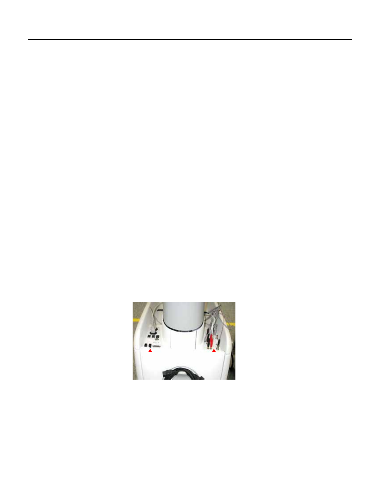
GE MEDICAL SYSTEMS
IRECTION 2300164-100, REVISION 7VIVID™ 3 PRO/VIVID™ 3 SERVICE MANUAL
D
3-5-2 Connecting Peripherals
Peripheral devices, such as a VCR or printer, are connected to the Vivid™ 3 ultrasound unit using the
rear panel connectors. Ensure that all peripheral devices connected to the ultrasound unit comply with
national safety requirements for medical equipment, including IEC601, CSA22.2, AS3200.1 and UL544.
The Vivid™ 3 ultrasound unit can operate with one or more of the following types of on-board
peripherals:
•VCR
• Black & White (B/W) Printer
•Color Printer
• Deskjet Color Printer HP6122
Note: Each of the peripherals have European and US versions. For a complete list of recommended
peripherals, refer to the Vivid™ 3 Pro/Vivid™ 3 Expert User Manual. For information for each
peripheral device, refer to the manufacturer’s manual.
On-board peripherals must be connected to one of the two available auxiliary power supplies on the
right rear panel. The total load on both auxiliary AC outlets should not exceed 500 VA. This means
8 Amp @ 100-120V AC or 4 Amp @ 220-240V AC.
Voltages are set according to local country voltage, as described in the Voltage Level Checks section,
on page 3-31.
For more details about peripherals installation refer to Vivid™ 3 Peripherals Installation Manual.
3-5-2-1 Rear Panel Connectors
The Vivid™ 3 ultrasound unit is equipped with two rear panels that provide the connections for
peripheral devices, as shown in Figure 3-14 below.
Note: Right and left are determined from the front of the unit. Refer to the Right Rear Panel Connectors
section, on page 3-24, and to the Left Rear Panel Connectors section, on page 3-25, for details
about each panel.
Right Rear Panel
Left Rear Panel
Figure 3-14 Rear Panel Connectors Rear View
Chapter 3 - Installation 3-23
Page 86

GE MEDICAL SYSTEMS
IRECTION 2300164-100, REVISION 7VIVID™ 3 PRO/VIVID™ 3 SERVICE MANUAL
D
3-5-2-1-1 Right Rear Panel Connectors
Table 3-9 describes the connectors included in the right rear panel (shown in Figure 3-15):
1
2
3
4
5
Figure 3-15 Right Rear Panel Connectors
Table 3-9 Right Rear Panel Connectors
Name Description
1. AUXILIARY AC OUTLET
For use with external peripherals. Voltages are set according to local country
voltage.
3
6
7
8
For use with external peripherals. Voltages are set according to local country
2. AUXILIARY AC OUTLET
3. THERMAL CIRCUIT BREAKERS Three 4A thermal circuit breakers for fuse protection.
4. NETWORK For the network connection.
5. MODEM For use with the service platform (iLinq).
6. RS 232 (2) Not in use.
7. USB For GE Service usage only (not for external USB devices).
8. PARALLEL PORT 25 pin connector for use with the external peripherals.
voltage. If additional auxiliary outlets are required, use the special cable
provided by GE. DO NOT attempt to connect additional peripherals using an
external wall outlet.
3-24 Section 3-5 - Completing the Hardware Installation
Page 87

GE MEDICAL SYSTEMS
IRECTION 2300164-100, REVISION 7VIVID™ 3 PRO/VIVID™ 3 SERVICE MANUAL
D
3-5-2-1-2 Left Rear Panel Connectors
Table 3-10 describes the connectors included in the left rear panel (shown in Figure 3-16):
1
2
4
7
8
9
10
Figure 3-16 Left Rear Panel Connectors
Table 3-10 Left Rear Panel Connectors
Name Description
3
5
6
11
12
1. VCR-RS 232 (1) One standard 9-pin RS232 (1) connector for VCR control (COM 1).
2. S-VIDEO OUT Y/C Video Out: 4 pin connector for output to an S-VHS VCR.
3. S-VIDEO IN Y/C Video In: 4 pin connector for input from an S-VHS VCR.
4. VIDEO OUT B/W BNC connector for composite B/W video output to a hard copy printer.
5. VIDEO OUT 1 BNC connector for composite color video output (PAL or NTSC).
6. VIDEO OUT 2 BNC connector for composite color video output (PAL or NTSC).
7. AUDIO IN (RIGHT) RCA jack.
8. AUDIO IN (LEFT) RCA jack.
9. AUDIO OUT (RIGHT) RCA jack.
10. AUDIO OUT (LEFT) RCA jack.
11. MIC Microphone input.
12. PRINT TRIG.
BNC connector for the exposure control of a multi-imager or another peripheral
activated by pressing Print B.
Chapter 3 - Installation 3-25
Page 88

GE MEDICAL SYSTEMS
IRECTION 2300164-100, REVISION 7VIVID™ 3 PRO/VIVID™ 3 SERVICE MANUAL
D
3-5-2-2 Connecting the VCR
1) Place the VCR on the peripheral tray and connect the following:
Table 3-11 VCR Cables
From the VCR To the Left Panel DIP on VCR Right Panel
S-Video IN S-Video OUT (Y/C OUT) 1-4 OFF (down)
S-Video OUT S-Video IN (Y/C OUT) 5-6 ON (up)
Audio IN Audio OUT
Audio OUT Audio IN
BE Control (RS-232) VCR RS 232 (1)
2) Install the VCR according to the VCR installation schematics, see Figure 8-159 on page 8-161.
3) After connecting the remaining peripherals and switching the system on, configure the VCR
settings, as described in the VCR/ECG Tab section, on page 3-45.
For more details about peripherals installation refer to the Vivid™ 3 Peripherals Installation Manual.
3-5-2-3 Connecting the Black & White Printer
1) Place the printer on the peripheral tray and connect the following cables as shown in Table 3-12.
Table 3-12 Black & White Printer Cables
From the Printer To the Left Panel
Video IN Composite Video OUT B/W
External Trigger Print Trigger
Power Cable Right Connectors Panel AC outlet
2) Install the printer according to the printer’s installation schematics, see Figure 8-110 on page -126.
3) After connecting the remaining peripherals and switching the system on, configure the printer
settings, as described in the Printers Tab section, on page 3-43.
For more details about peripherals installation refer to the Vivid™ 3 Peripherals Installation Manual.
3-5-2-4 Connecting the Color Printer
1) Place the color printer in the printer compartment above the B/W printer and VCR on the peripheral
tray, using an additional shelf.
2) Connect the following cables as shown in Ta bl e 3 -1 3:
3-26 Section 3-5 - Completing the Hardware Installation
Page 89

GE MEDICAL SYSTEMS
IRECTION 2300164-100, REVISION 7VIVID™ 3 PRO/VIVID™ 3 SERVICE MANUAL
D
Table 3-13 Color Printer Cables
To the Cables
From the Color Printer
Video IN Composite/Video OUT 1
External Trigger Print Trigger
AC IN AC Power Cable
underneath the Control Console
Note: All the color printer cables are located in the left storage compartment under the metal cover.
3) After connecting the remaining peripherals and switching the system ON, configure the printer
settings, as described in the Printers Tab section, on page 3-43.
For more details about peripherals installation, refer to the Vivid™ 3 Peripherals Installation Manual.
3-5-2-5 Connecting the DeskJet Color Printer HP6122
Note: If there is sufficient space, the DeskJet Color Printer may be installed under the control
console. Alternatively, it will require a suitable stand or table to be positioned in close
proximity to the Vivid™ 3 scanner - at a distance of not more than 1m (3.3 ft) from the power
connection to the Vivid™ 3 unit.
WARNING: Whenever moving the Vivid™ 3 scanner, the DeskJet Color Printer must be
disconnected from the scanner. DO NOT attempt to move the two units simultaneously without
first disconnecting them. After relocation, re-connect the printer to the scanner.
1) Place the DeskJet color printer on the shelf below the control console (or alternatively on the
designated stand or table, adjacent to the unit).
2) Connect the following cables as shown in Ta bl e 3- 14 :
Table 3-14 DeskJet Color Printer Cables
From the Color Printer To the Right Panel
Parallel Port Connector Parallel Port
AC IN (AC Dual Power cable) Panel AC outlet
3) After connecting the remaining peripherals and switching the system ON, configure the printer
settings, as described in the Printers Tab section, on page 3-43.
For more details about peripherals installation refer to the Vivid™ 3 Peripherals Installation Manual.
Chapter 3 - Installation 3-27
Page 90

GE MEDICAL SYSTEMS
IRECTION 2300164-100, REVISION 7VIVID™ 3 PRO/VIVID™ 3 SERVICE MANUAL
D
3-5-3 Connecting Probes
The Vivid™ 3 ultrasound unit operates with various types of probes that are used for scanning patients,
including flat phased, convex and linear electronic array probes. Once connected, the probes can be
selected for different applications.
Probe connectors on the unit’s control panel are as follows:
• Three active probe connectors (one for a pencil probe), and a fourth, inactive port on the right side
of the unit, which is used for parking.
OR
• Four active probe connectors (one for a pencil probe).
Probes can be connected or changed any time, as described below:
1) Inspect the probe socket to verify that it is free of debris.
2) Hold the rectangular probe connector vertically so that the probe’s cable points upwards.
3) Rotate the probe locking latch counterclockwise to the unlock (horizontal) position.
4) Gently insert the connector into one of the matching sockets on the front of the unit. Gently push
the connector in as far as possible.
5) Rotate the locking latch 90 degrees clockwise to lock the connector into place (vertical).
NOTE: It is not necessary to turn OFF power to connect or disconnect a probe.
3-5-3-1 Available Probes
The following probes are available for use with the Vivid™ 3 ultrasound unit:
Table 3-15 Available Probes
P/N Description
2232337 3S SECTOR (new design)
2259135 7L (546L)
2259145 10L (739L) LINEAR
2259153 C358 PROBE (OUTSIDE JAPAN)
2259206 I739L LINEAR
2295377 12L
2263669 7S SECTOR
2266328 10S
2169773 P509 (Japan)
2259246 T739L LINEAR
KN100011 5T TEE MULTIPLANE
KN100022 6T (Super TEE)
KN100023 8T (Ped TEE)
KN100072 9T(PED TEE) (for RFI systems only)
KZ200476 5S SECTOR
TE100024 Pencil P2D
TQ100002 Pencil P6D
KZ200476 Adaptor PAMPTE/6Tv
2301954 E721
KQ100006 i8L
KW100011 i13L
3-28 Section 3-5 - Completing the Hardware Installation
Page 91

GE MEDICAL SYSTEMS
IRECTION 2300164-100, REVISION 7VIVID™ 3 PRO/VIVID™ 3 SERVICE MANUAL
D
3-5-4 Connecting the ECG
The internal ECG is connected into a rectangular-shaped socket on the patient trace (I/O) panel. The patient
trace (I/O) panel is located on the front of the ultrasound unit, as shown in Figure 3-11 on page 3-16. Each
socket is clearly labelled and color coded, as shown in Figure 3-17 below.
Figure 3-17 Connection Sockets for ECG Cables
1 Footswitch (black)
2 Phono (blue)
3 ECG (green)
4 External ECG (yellow)
The ECG cable is a modular cable consisting of four different cable parts. The main part (trunk) is a
single cable connecting to the unit at one end, and providing a cable splitter device at the other end.
The splitter contains five receptacles, only three of which are used with the Vivid™ 3 Pro/Vivid™ 3
Expert ultrasound unit.
Three color coded electrode cables are inserted into the splitter in the appropriate color-coded
receptacles. Each electrode cable hooks up to the appropriate stick-on electrode by a clip-type
connector. The color coding of the electrodes follows one of two standards that are common in different
parts of the world. The cable splitter has a drawing defining the color codes, names and electrode
placements for each of the three cables, as shown in Figure 3-18 on page 3-30.
Chapter 3 - Installation 3-29
Page 92

GE MEDICAL SYSTEMS
IRECTION 2300164-100, REVISION 7VIVID™ 3 PRO/VIVID™ 3 SERVICE MANUAL
D
AHA (Americas, Japan)
IEC (Europe, Asia, ROW)
Figure 3-18 ECG Cable and Electrode Placement
Note: For optimal ECG operation, use only electrodes that meet universal standards - see Ta bl e 3 -1 6.
Table 3-16 ECG Cable Types
Description Part No.
Full ECG Cable Kit - AHA (Americas, Japan) 2256477
Black wire (LA) 2269982-3
White wire (RA) 2269982
Green wire (RL) 2269982-2
Full ECG Cable Kit - IEC (Europe, Asia, ROW) 2256478
Yellow wire (L) 2269983
Red wire (R) 2269983-3
Black wire (N) 2269983-2
3-30 Section 3-5 - Completing the Hardware Installation
Page 93

GE MEDICAL SYSTEMS
IRECTION 2300164-100, REVISION 7VIVID™ 3 PRO/VIVID™ 3 SERVICE MANUAL
D
3-5-5 Connecting the Unit to a Power Source
The initial connection of the Vivid™ 3 ultrasound unit to a power source should be performed by a
qualified person, authorized by GE Medical Systems. Use only the power cords, cables and plugs
provided by or designated by GE Medical Systems to connect the unit to the power source.
CAUTION: Verify compliance with all electrical and safety requirements and check the power cord to
verify that it is intact and of hospital-grade before connecting the unit to the power source. Products
equipped with a power source (wall outlet) plug should be connected to the fixed power socket that has
a protective grounding conductor. Never use an adapter or converter to connect with a power source
plug (for example, a three-prong to two-prong converter).
3-5-5-1 Voltage Level Checks
The following voltage level checks are required:
1) Check the rating label at the rear of the ultrasound unit, as described in Chapter 1 - Introduction,
and verify that your local AC Voltage corresponds to the voltage setting as indicated on the rating
label. The rating label indicates that the factory preset input AC voltage is one of the following:
•100 V
•120 V
• 220 - 240 V
2) Verify the maximum power requirement as follows:
• Maximum power = 1.2 KVa (the system might need)
• 100 V 60-50 Hz 8A
• 120 V 60-50 Hz 8A
• 220 - 240 V 60-50 Hz 4A
DANGER: Failure to provide an adequate earth circuit (Ground) may cause electrical shock and
serious injury.
Chapter 3 - Installation 3-31
Page 94

GE MEDICAL SYSTEMS
IRECTION 2300164-100, REVISION 7VIVID™ 3 PRO/VIVID™ 3 SERVICE MANUAL
D
3-5-5-2 Connecting the Ultrasound Unit to the Electrical Outlet
Note: To help assure grounding reliability, connect to a hospital-grade or “hospital only” grounded
power outlet. If using the ultrasound unit with an external UPS system, follow all the grounding
and applicable safety standards as documented both in this manual and the external UPS
manufacturer’s manual. The external UPS system is to be considered the AC outlet.
1) Verify that the AC wall outlet is of the appropriate type.
2) Turn off the AC circuit breaker at the rear of the unit.
3) Plug the power cord connector into the AC input socket, and secure it in place using the attached
clip - see Figure 3-19
Cable Clip
Mains Power Cable
Figure 3-19 Circuit Breaker and Power Cable on Back of Scanner
4) Plug the other end of the power cord to the AC wall outlet. Allow sufficient slack so that the plug will
not be pulled out if the unit is slightly moved. The remaining length of the cord should be looped
and hung on the hook provided.
DANGER: To avoid the risk of fire, power to the system must be supplied from a separate,
properly rated outlet. It is recommended to use a dedicated power outlet. The power plug should
not, under any circumstances, be altered to a configuration rated less than that specified for the
current. DO NOT use an extension cord or adaptor plug. Refer to the Electrical Requirements
section, on page 2-3 for more details.
Circuit Breaker
3-32 Section 3-5 - Completing the Hardware Installation
Page 95

GE MEDICAL SYSTEMS
IRECTION 2300164-100, REVISION 7VIVID™ 3 PRO/VIVID™ 3 SERVICE MANUAL
D
3-5-5-3 Disconnecting the Ultrasound Unit from the Electrical Outlet
CAUTION: Whenever disconnecting the Vivid™ 3 unit from the electrical outlet, always observe
the safety precautions. First unplug the mains power cable from the wall outlet socket, then from
the unit itself. Remove by pulling on the cable connector - DO NOT pull on the cable.
1) Turn OFF the AC circuit breaker on the rear of the unit.
2) Unplug the mains power cable from the AC wall outlet socket.
3) Unplug the mains power cable connector from the AC input socket (refer to Figure 3-19 on page 3-32).
NOTICE
Disconnecting the Mains Power Cable before switching OFF the Circuit Breaker will activate the
uninterruptible power system (UPS) in the back-end processor, forcing an ordered shutdown of the
system.
3-5-6 Switching the System ON/OFF
3-5-6-1 Switching the System ON
1) Verify that the ultrasound unit has been connected to the power supply and that the circuit breaker
is ON, as described in the Connecting the Ultrasound Unit to the Electrical Outlet section, on
page 3-32.
NOTICE
When AC power is applied to the scanner, the On/Off button on the control console illuminates amber,
indicating the Back-end Processor is in Standby mode.
2) Hold down the
On/Off button on the control panel for 3 seconds. The system automatically
performs an initialization sequence which includes the following:
• Loading the operating system.
• Running a quick diagnostic check of the system.
• Detecting connected probes.
The system first enters 2D-Mode with the probe and application that were last used before the system
was shut down. If the probe has been removed since the system was last used, the currently connected
probes and their available applications are displayed and selected by default.
3-5-6-2 Switching the System OFF
NOTE: After turning OFF the system, wait at least 10 seconds before turning it on again. The system may not
be able to boot-up if power is recycled too quickly.
The system can be switched OFF in one of three ways:
• By holding down the On/Off button for 3 seconds, the unit will perform an automatic shutdown
sequence that protects the hard disk and switches into an energy-saving standby mode.
• By holding down the On/Off button for more than 3 seconds, the unit will display a shutdown menu,
enabling the operator to shutdown the system to standby mode or to perform a full shutdown (see
Figure 3-20 on page 3-34).
• By holding down the On/Off button for more than 10 seconds, the unit will perform an emergency
shutdown. It is not recommended to use this type of shutdown unless the application is locked and
no other operation can be performed.
Chapter 3 - Installation 3-33
Page 96

GE MEDICAL SYSTEMS
IRECTION 2300164-100, REVISION 7VIVID™ 3 PRO/VIVID™ 3 SERVICE MANUAL
D
Figure 3-20 Shut-Down Options Screen
3-34 Section 3-5 - Completing the Hardware Installation
Page 97

GE MEDICAL SYSTEMS
IRECTION 2300164-100, REVISION 7VIVID™ 3 PRO/VIVID™ 3 SERVICE MANUAL
D
Section 3-6 System Configuration
Once all the required peripherals have been installed and the unit has been switched on, configure the
system settings in the System Configuration window tabs. Refer to the Vivid™ 3 Pro/Vivid™ 3 Expert
User Manual for additional information about system configuration.
3-6-1 Adjusting the Display Monitor
The display monitor’s contrast and brightness controls may need periodic adjustment due to changes
in ambient light. They can be adjusted using the Contrast and Brightness buttons on the front part of
the display monitor.
All display monitor controls, other than the contrast and brightness controls, are factory adjusted for
optimum settings and usually do not require further adjustment.
For details on adjusting the display monitor settings, refer to the Monitor Operation section, on page 6-9.
3-6-2 Hospital Info Tab
1) Press Config on the alphanumeric keyboard. The System Configuration window is displayed with
the Hospital Info tab selected, as shown below:
Figure 3-21 Hospital Info Tab
2) In the Hospital Info tab, enter the required information in the appropriate fields.
3) Trackball to the OK button and press Select.
Chapter 3 - Installation 3-35
Page 98

GE MEDICAL SYSTEMS
IRECTION 2300164-100, REVISION 7VIVID™ 3 PRO/VIVID™ 3 SERVICE MANUAL
D
3-6-3 System Tab
1) Press Config on the alphanumeric keyboard. The System Configuration window is displayed.
2) Trackball to the System tab and press Select. The software information is displayed in the upper
portion of the tab, as shown below:
Figure 3-22 System Tab
Note: To avoid corruption of the archives, do not change the date.
3) In the STANDBY timeout field of the Time Out (sec) area, enter the amount of time (in seconds)
after which the system switches to standby mode when it is not being used.
4) In the Date/Time area, set the date and time, as follows:
• Trackball to the Set button and press Select. Use the alphanumeric keyboard to select the
current date.
• Select the format of the date and time display, for example, DD/MM/YYYY.
• Select the hour mode, for example, 24 hour or 12 hour.
• In the Default PC Cursor Position area, specify the default location of the PC cursor on the
screen by entering the X and Y coordinates into the X and Y fields. The Figure 3-22, above
indicates the recommended default factory setup for X and Y.
5) In the Footswitch area, define the functions that will be performed when each of the three pedals on
the footswitch is used by selecting the relevant function from the Left, Mid and Right drop-down lists.
6) Select the system language from the Language dropdown list.
7) Trackball to the OK button and press Select.
3-36 Section 3-6 - System Configuration
Page 99

GE MEDICAL SYSTEMS
IRECTION 2300164-100, REVISION 7VIVID™ 3 PRO/VIVID™ 3 SERVICE MANUAL
D
3-6-4 Connectivity Tab
For details on the Connectivity tab, refer to the Connectivity Setup section, on page 3-50.
3-6-5 Archive Tab
1) Press Config on the alphanumeric keyboard. The System Configuration window is displayed.
2) Trackball to the Archive tab and press Select. The Archive tab is displayed, as shown below:
Figure 3-23 Archive Tab
Note: The Archive tab will display even if the Archive Package option is not installed.
3) Select Display patients gender on screen to display the patient’s gender in the patient information
area of the scanning screen (not applicable to OB applications).
4) Select Delete Confirmation to prompt the user to confirm delete commands.
5) Select the type of weight measurement to be used during examinations and in the Patient Details
pages from the Weight Units dropdown list.
6) Select the type of height measurement to be used during examinations and in the Patient Details
pages from the Height Units dropdown list.
Chapter 3 - Installation 3-37
Page 100

GE MEDICAL SYSTEMS
IRECTION 2300164-100, REVISION 7VIVID™ 3 PRO/VIVID™ 3 SERVICE MANUAL
D
7) Select the patient ID page type from the Patient ID Page Type dropdown list, as follows:
• Type A: displays patient ID, last and first name, weight, height, BSA, BP and other fields.
• Type B: displays all Type A fields except patient ID.
• Type C: displays all Type A fields except patient ID, weight, height and BSA. It also displays
the sonographer’s name.
• Type D: displays all Type A fields except patient ID, weight, height, BSA and BP.
8) Select the patient data to be displayed in the patient information area of the scanning screen title
bar from the Title Additional Patient Info dropdown list.
9) Select the type of media, to which data is stored during backup, from the Backup Device Is
dropdown list.
10) Select Eject MO Disk on Shutdown to have the system automatically eject the backup media
when the unit is shut down.
11) Enter the location of ASCII files in the user (U:\path\) partition of the internal hard disk in the Export
To Excel Path field.
12) Select Enter From Halves to Quad to enable the user to toggle between viewing a single image,
two images or four images on the screen simultaneously (Quad View).
13) Select Preview Cine Before Store to display cineloops before they are stored.
• When the FlexiView option is installed the time period (in seconds) after which a cineloop is
automatically stored in the archive without interrupting the user’s monitoring must be set in the
FlexiView Time Interval[sec] field. Figure 3-23 on page 3-37 indicates the recommended
default factory setup.
14) Trackball to the OK button and press Select.
3-38 Section 3-6 - System Configuration
 Loading...