

Page 1

GE
Intelligent Platforms
Programmable Control Products
VersaPoint* I/O System
Profibus-DP NIU
User’s Manual, GFK-1911B
March 2010
Page 2

GFL-002
Warnings, Cautions, and Notes
as Used in this Publication
Warning
Warning notices are used in this publication to emphasize that hazardous voltages,
currents, temperatures, or other conditions that could cause personal injury exist in this
equipment or may be associated with its use.
In situations where inattention could cause either personal injury or damage to equipment,
a Warning notice is used.
Caution
Caution notices are used where equipment might be damaged if care is not taken.
Note: Notes merely call attention to information that is especially significant to
understanding and operating the equipment.
This document is based on information available at the time of its publication. While efforts
have been made to be accurate, the information contained herein does not purport to cover all
details or variations in hardware or software, nor to provide for every possible contingency in
connection with installation, operation, or maintenance. Features may be described herein
which are not present in all hardware and software systems. GE Intelligent Platforms assumes
no obligation of notice to holders of this document with respect to changes subsequently made.
GE Intelligent Platforms makes no representation or warranty, expressed, implied, or statutory
with respect to, and assumes no responsibility for the accuracy, completeness, sufficiency, or
usefulness of the information contained herein. No warranties of merchantability or fitness for
purpose shall apply.
* indicates a trademark of GE Intelligent Platforms, Inc. and/or its affiliates. All other
trademarks are the property of their respective owners.
©Copyright 2010 GE Intelligent Platforms, Inc.
All Rights Reserved
Page 3
Contact Information
If you purchased this product through an Authorized Channel Partner, please contact the seller
directly.
General Contact Information
Online technical support and
1H2Hhttp://www.ge-ip.com/support
GlobalCare
Additional information 3Hhttp://www.ge-ip.com/
Solution Provider 4Hsolutionprovider.ip@ge.com
Technical Support
If you have technical problems that cannot be resolved with the information in this guide, please
contact us by telephone or email, or on the web at
5Hwww.ge-ip.com/support
Americas
Online Technical Support 6H7Hwww.ge-ip.com/support
Phone 1-800-433-2682
International Americas Direct Dial 1-780-420-2010 (if toll free 800 option is unavailable)
Technical Support Email 8H9Hsupport.ip@ge.com
Customer Care Email 10H11Hcustomercare.ip@ge.com
Primary language of support English
Europe, the Middle East, and Africa
Online Technical Support 12H13Hwww.ge-ip.com/support
Phone +800-1-433-2682
EMEA Direct Dial +352-26-722-780 (if toll free 800 option is unavailable or if
dialing from a mobile telephone)
Technical Support Email 14H15Hsupport.emea.ip@ge.com
Customer Care Email 16H17Hcustomercare.emea.ip@ge.com
Primary languages of support English, French, German, Italian, Czech, Spanish
Asia Pacific
Online Technical Support 18H19Hwww.ge-ip.com/support
+86-400-820-8208 Phone
+86-21-3217-4826 (India, Indonesia, and Pakistan)
Technical Support Email
20H21Hsupport.cn.ip@ge.com (China)
22H23Hsupport.jp.ip@ge.com (Japan)
24H25Hsupport.in.ip@ge.com (remaining Asia customers)
26H27Hcustomercare.apo.ip@ge.com Customer Care Email
28Hcustomercare.cn.ip@ge.com (China)
Page 4

Page 5

Contents
Chapter 1 Introduction ........................................................................................... 1-1
Features ............................................................................................................................ 1-2
Advantages ....................................................................................................................... 1-2
I/O Station Capacity.................................................................................................. 1-2
What’s In This Manual....................................................................................................... 1-3
Other Documents You’ll Need........................................................................................... 1-4
Example Plant ...................................................................................................................1-5
Chapter 2 The Profibus NIU.................................................................................... 2-1
The Profibus System ......................................................................................................... 2-2
Typical Profibus-DP VersaPoint I/O Station ............................................................. 2-2
Structure of a VersaPoint I/O Station .......................................................................2-3
The Profibus-DP Network Interface Unit ........................................................................... 2-4
Features ................................................................................................................... 2-4
Comparison of Features ........................................................................................... 2-5
Items Used with the NIU........................................................................................... 2-6
Ordering Information................................................................................................. 2-6
Connectors on the NIU...................................................................................................... 2-7
Profibus Connector ................................................................................................... 2-7
Power Connector...................................................................................................... 2-8
NIU Power ................................................................................................................2-8
DIP Switches on the NIU................................................................................................... 2-9
LEDS on the NIU............................................................................................................. 2-10
DPV1 Communications for Profibus NIU
IC220PBI002 ................................................................................................................... 2-11
NIU Specifications ........................................................................................................... 2-12
Chapter 3 VersaPoint Modules............................................................................... 3-1
Modules in a VersaPoint Station ....................................................................................... 3-2
Input/Output Modules ............................................................................................... 3-3
Terminal Points......................................................................................................... 3-3
Power Losses for I/O Modules ................................................................................. 3-4
Analog Modules ........................................................................................................ 3-5
Power Terminal Modules .......................................................................................... 3-6
Segment Terminal Modules ..................................................................................... 3-7
Parts of a VersaPoint Module ........................................................................................... 3-8
The Electronics Base ........................................................................................................ 3-9
Diagnostic and Status Indicators ............................................................................ 3-10
Module Color Coding.............................................................................................. 3-10
Status LEDs and I/O Points.................................................................................... 3-11
GFK-1911B v
Page 6

Contents
Connectors .............................................................................................................3-12
Module Dimensions......................................................................................................... 3-14
Chapter 4 Installation.............................................................................................. 4-1
Parts of a VersaPoint I/O Station ...................................................................................... 4-2
End Plate .................................................................................................................. 4-2
End Clamps .............................................................................................................. 4-2
Planning Module Sequence in the I/O
Station ............................................................................................................................... 4-3
Locations for Analog Modules .................................................................................. 4-3
Power for the Station......................................................................................................... 4-4
Electrical isolation ..................................................................................................... 4-5
Dangerous voltage! .................................................................................................. 4-5
Setting the NIU Switches .................................................................................................. 4-6
Keying Connectors and Modules ...................................................................................... 4-7
Installing Modules on the DIN Rail .................................................................................... 4-8
Removing Modules................................................................................................... 4-9
Replacing a Module .................................................................................................. 4-9
Connecting Unshielded Cables....................................................................................... 4-10
Connecting Shielded Cables........................................................................................... 4-11
Connecting Shielded Cables to the Shielded Terminal Strip ................................. 4-11
Repositioning the Shield Clamp .............................................................................4-12
Grounding........................................................................................................................ 4-13
Grounding the NIU and Power Modules................................................................. 4-13
Required Additional Grounding .............................................................................. 4-13
Installing the Profibus Cable ........................................................................................... 4-14
Profibus Cable Specifications................................................................................. 4-14
The Profibus Cable Connector ............................................................................... 4-15
Shielding the Profibus Cable .................................................................................. 4-15
Bus Termination ..................................................................................................... 4-16
Connecting Power at the NIU.......................................................................................... 4-17
Providing the 24V Segment Supply (US ) at the NIU ............................................. 4-17
Fusing for Short Circuit Protection ......................................................................... 4-17
Replacing Power and Segment Terminal
Fuses............................................................................................................................... 4-18
Connecting Sensors and Actuators................................................................................. 4-19
Connecting Discrete Devices .................................................................................4-19
Connections for Discrete Input Modules ................................................................ 4-19
Connections for Discrete Output Modules.............................................................. 4-19
Connecting 2-Wire Discrete Sensors and Actuators .............................................. 4-20
Connecting 3-Wire Discrete Sensors and Actuators .............................................. 4-20
Connecting 4-Wire Discrete Sensors and Actuators .............................................. 4-21
vi VersaPoint™ I/O System Profibus-DP NIU User’s Manual– August 2005 GFK-1911B
Page 7

Contents
Connecting Analog Devices ...................................................................................4-22
Connecting Field Devices to an Analog Input Module ........................................... 4-22
Connecting a Thermocouple Analog Input Module ................................................ 4-22
Connecting Field Devices to an Analog Output Module......................................... 4-23
Danger of creating ground loops! ........................................................................... 4-23
Connection of actuators for Signal Cables Longer than 10 Meters (32.8
Ft) ........................................................................................................................... 4-23
Module Labeling .............................................................................................................. 4-24
Chapter 5 Power for the Station............................................................................. 5-1
Supply of the Profibus-DP Network
Interface Unit .....................................................................................................................5-2
The Logic Circuit: UL................................................................................................. 5-3
The Analog Circuit: U
The Main Circuit: UM................................................................................................. 5-4
Segment Circuit: US.................................................................................................. 5-5
Electrical Isolation ............................................................................................................. 5-8
Electrical Isolation: Profibus ..................................................................................... 5-8
Electrical Isolation: I/O.............................................................................................. 5-8
Electrical Isolation: Discrete Modules....................................................................... 5-9
Electrical isolation: Analog module......................................................................... 5-10
Electrical isolation: Other ........................................................................................ 5-11
VersaPoint Power Consumption Example ...................................................................... 5-12
........................................................................................... 5-3
ANA
Chapter 6 Diagnostics ............................................................................................ 6-1
Local Diagnostics .............................................................................................................. 6-2
LEDS on the Network Interface Unit ........................................................................ 6-2
Possible LED combinations...................................................................................... 6-3
Determining the Error Cause and Remedy from the NIU LEDs ............................... 6-4
Power and Segment Module LEDs ........................................................................ 6-10
I/O Module LEDs ....................................................................................................6-11
Local Diagnostics Example .................................................................................... 6-12
Example Station for Error Identification.................................................................. 6-12
Diagnostics on the Profibus Master ................................................................................ 6-14
Profibus Standard Diagnostics ............................................................................... 6-14
Profibus – Device-Specific Diagnostics (For NIU Model IC670PBI002) ................ 6-17
Profibus – Device-Specific Diagnostics (For NIU Model IC670PBI001) ................ 6-18
Module Diagnostics, NIU Model IC670PBI002 ...................................................... 6-19
Chapter 7 Configuration ......................................................................................... 7-1
Powerup Autoconfiguration of the NIU.............................................................................. 7-2
Configuration of the Profibus Master ................................................................................ 7-3
The GSD File............................................................................................................ 7-3
GFK-1911B Contents vii
Page 8

Contents
Configuring the Profibus Master ............................................................................... 7-3
Configuring Profibus Parameters for the Profibus Master CPU ............................... 7-5
Network Settings for the Profibus Master................................................................. 7-6
Adding the Profibus NIU to the
IC693CPU366 Master Configuration ................................................................................ 7-8
Configuring the Modules in the I/O Station ....................................................................... 7-9
Configuring Module Data Areas ............................................................................. 7-10
Byte Rotation for 16-Point Discrete Modules ......................................................... 7-12
Byte Rotation for 32-Point Discrete Modules ......................................................... 7-12
Configuring DP-V1 Settings for the Profibus NIU................................................... 7-13
Dynamic Configuration .................................................................................................... 7-16
Indexes ................................................................................................................... 7-16
Index 6: Activation/deactivation of terminals and slots Access: Read and write................ 7-16
Index 7: Read back active/inactive terminals and slots .................................................. 7-17
Index 8: Read/write ID Access: Read and write ............................................................ 7-17
Accessing the Indexes via Process Data ...............................................................7-17
Specify an ID .......................................................................................................... 7-20
Chapter 8 Communications.................................................................................... 8-1
Types of Acyclic Communication ...................................................................................... 8-2
Acyclic Communication Via the Class 1 Master ....................................................... 8-2
Acyclic Communication Via the Class 2 Master ....................................................... 8-2
PCP Communication Basics ............................................................................................. 8-3
Device Parameter Data ............................................................................................8-3
Acyclic Communication in DP/V1 Mode............................................................................ 8-4
Accessing NIU Data ................................................................................................. 8-5
Accessing Module Data............................................................................................ 8-5
DP/V1 Examples ...................................................................................................... 8-9
PCP Communication Via Process Data
(Class1 Master in DP/V0 Mode)...................................................................................... 8-17
Mechanism for Transmission in the Process Data ................................................. 8-17
Process Data Width of the Virtual C1 “Module” ..................................................... 8-17
Responses.............................................................................................................. 8-21
Examples of Communications using a Virtual C1 Module ..................................... 8-22
Format of the Parameter Telegram................................................................................. 8-29
NIU Parameters...................................................................................................... 8-29
Module Parameters ................................................................................................8-30
Object Dictionary for the Profibus-DP/V1 NIU........................................................ 8-31
Error Codes for DP/V1 and VC1
Communication ............................................................................................................... 8-35
Error Codes for PCP Communication .................................................................... 8-36
Other Error Messages ............................................................................................ 8-36
viii VersaPoint™ I/O System Profibus-DP NIU User’s Manual– August 2005 GFK-1911B
Page 9

Contents
Appendix A Reference Data.......................................................................................A-1
I/O Station Information ......................................................................................................A-2
Ambient Conditions ...........................................................................................................A-3
Mechanical Demands........................................................................................................A-4
Noise Immunity Test .........................................................................................................A-4
Electrical Specifications ....................................................................................................A-5
Cables ...............................................................................................................................A-7
I/O Modules .......................................................................................................................A-7
Air and Creepage Distances .............................................................................................A-8
Test Voltages ....................................................................................................................A-9
Appendix B Glossary .................................................................................................B-1
Appendix C Output Module Derating ........................................................................C-1
Power Loss of the Housing Within the
Operating Temperature Range Depending
on the Ambient Temperature ............................................................................................C-2
Power Loss of the Housing ...............................................................................................C-3
Permissible Operating Temperature Range .....................................................................C-4
Appendix D The NIU GSD File ...................................................................................D-1
GSD File for NIU Version IC220PBI002 ...........................................................................D-2
GSD File for NIU Version IC220PBI001 .........................................................................D-21
GFK-1911B Contents ix
Page 10

Contents
x VersaPoint™ I/O System Profibus-DP NIU User’s Manual– August 2005 GFK-1911B
Page 11

Chapter
1
Introduction
The VersaPoint product family is a modular automation system. With
VersaPoint modules you can easily add one module to the next and build
functional units that meet your automation requirements exactly.
A set of interconnected VersaPoint I/O modules can be selected to suit the
application, and connected as a slave on a Profibus-DP network. The
interface between the network and the modules is a VersaPoint Profibus-DP
Network Interface Unit (NIU).
The NIU is located to the left of the other modules. Together, the NIU and
the modules selected for the application function as an I/O Station. The I/O
Station can include up to 63 I/O modules.
Within the VersaPoint station the bus connection, power supply, and power
distribution for the devices connected to the bus terminal are realized by
connecting modules together on the DIN rail.
Sensors and actuators are easily wired to the VersaPoint I/O modules via
spring-clamp terminals on the modules' removable connectors. These
connectors can be keyed so that they cannot be mixed up. If a module must
be exchanged the wiring does not need to be removed. Just remove the
connector from the terminal.
GFK-1911B 1-
1
Page 12

1
Features
Advantages
Characteristic VersaPoint features are:
– Modules can be easily installed/interconnected without tools.
– Automatic creation of isolated groups, current, data, and safety circuits
– Open, flexible, and modular structure
– Modules of varying point counts can be combined to create a
VersaPoint station that optimizes unit space while minimizing unit cost.
VersaPoint design offers the following advantages:
– Reduced control cabinet space.
– The amount of costly parallel wiring is reduced. Within a station, voltage
and data routing can be carried out without additional wiring.
– The modular structure makes it possible to assemble standard function
blocks in advance. Different parts of the system can be operated
independently of one another. This means that pretests can be carried
out when the system is set up and that the whole system can be
adapted and expanded.
I/O Station Capacity
– Up to 63 devices can be connected to an NIU (Depending on power
consumption. See chapter 5).
– The sum of all input and output data can be up to 184 bytes per station.
1-2 VersaPoint™ I/O System Profibus-DP NIU User’s Manual – August 2005 GFK-1911B
Page 13

What’s In This Manual
This manual contains the instructions and reference information needed to
plan and install a VersaPoint I/O Station on a Profibus-DP network.
Chapter 1 is a quick introduction to VersaPoint.
Chapter 2. The Profibus NIU, describes the Profibus Network Interface
Unit module, which connects the VersaPoint I/O Station to the Profibus
network.
Chapter 3. VersaPoint Modules, describes the parts and dimensions of
VersaPoint I/O and power modules.
Chapter 4. Installation, describes basic VersaPoint module installation
and cable connections.
Chapter 5 Power for the Station, explains how power is utilized by the
station and routed among the modules.
Chapter 6. Diagnostics, describes in detail the indications of the NIU and
module LEDs, as well as additional diagnostics features of the VersaPoint
station.
Chapter 7. Configuration, describes the configuration options of the
VersaPoint Profibus NIU.
Chapter 8. Communications, describes the data structures used for
communications with the Profibus NIU.
Appendix A. Reference Data, summarizes the standard data for a
VersaPoint Profibus I/O system..
Appendix B. Glossary explains many of the terms used in this manual.
Appendix C. Output Module Derating, describes how to calculate power
loss and operating temperature limits for I/O modules.
1
GFK-1911B Chapter 1 Introduction 1-3
Page 14
1
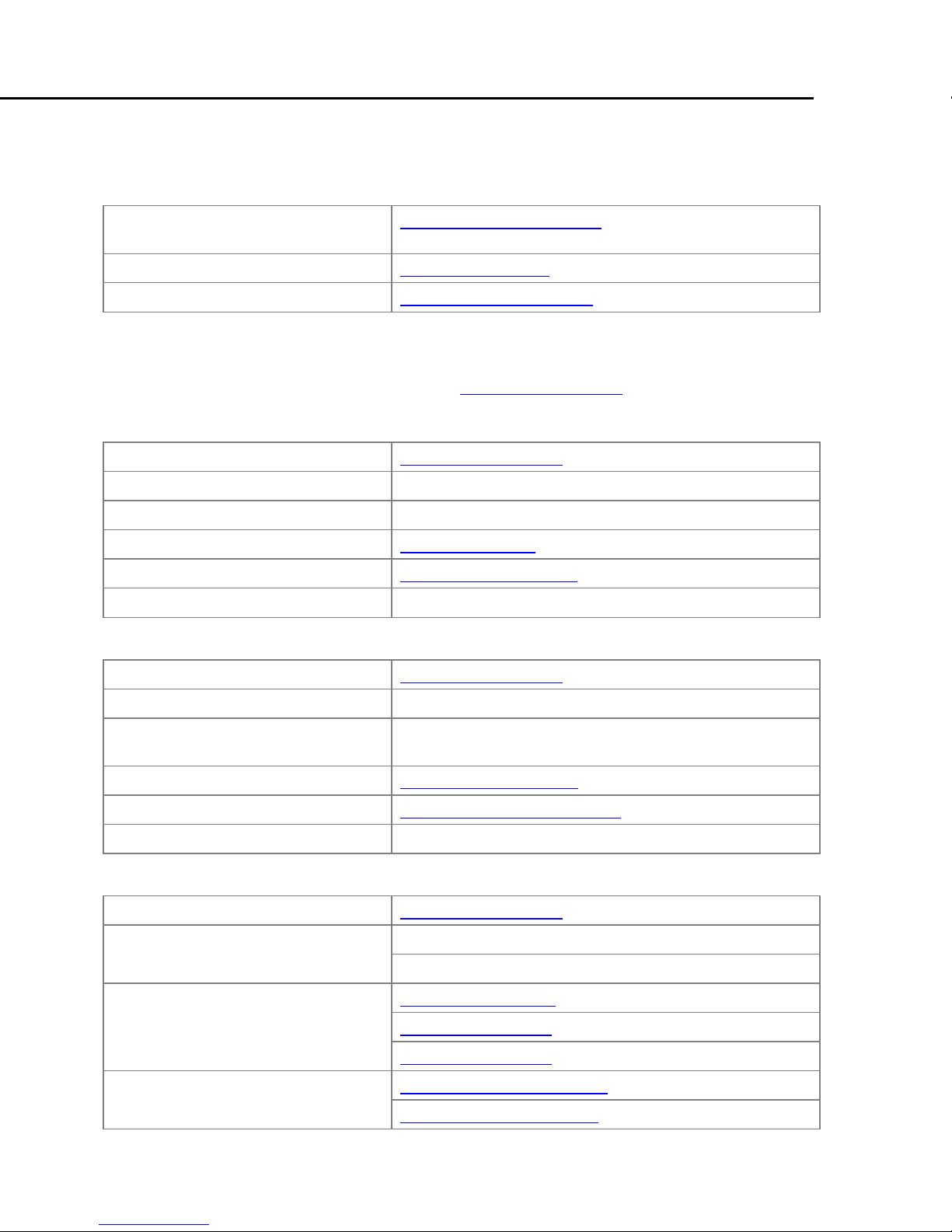
Other Documents You’ll Need
These documents are available online at http://www.ge-ip.com/, and on the
Infolink for PLC document library on CDs (catalog number IC690CDR002).
Check the GE website for the most up-to-date document versions
and other important product information.
Module Number Module Description Document Number
Discrete Input Modules
IC220MDL641 Input 24VDC Positive Logic 2 Points GFK-1901
IC220MDL642 Input 24VDC Positive Logic 4 Points GFK-1902
IC220MDL643 Input 24VDC Positive Logic 8 Points GFK-2000
IC220MDL644 Input 24VDC Positive Logic 16 Points GFK-2001
IC220MDL661 Input 24VDC Negative Logic 2 Points GFK-2002
Discrete Output Modules
IC220MDL721 Output 24VDC Positive Logic 2.0A 2 Points GFK-1903
IC220MDL751 Output 24VDC Positive Logic 0.5A 2 Ppoints GFK-2003
IC220MDL752 Output 24VDC Positive Logic 0.5A 4 Points GFK-1904
IC220MDL753 Output 24VDC Positive Logic 0.5A 8 Points GFK-2004
IC220MDL754 Output 24VDC Positive Logic 0.5A 16 Points GFK-1913
IC220MDL761 Output 24VDC Positive Logic 0.5A 2 Points GFK-2005
Special Function Modules
IC220BEM232 RS-232 Communications Module GFK-2394
IC220BEM485 RS-485/422 Communications Module GFK-2395
IC220MDD840 High-speed Counter 1 In/1 Out 24VDC GFK-2052
IC220MDD841 Absolute Encoder Module
IC220MDD842 Incremental Encoder Module
IC220STR001 Motor Starter Direct, 1.5KW/400VAC
IC220STR002 Motor Starter Direct, 3.7KW/400VAC
IC220STR003 Motor Starter Reversing
Analog Input Modules
IC220ALG220 Analog In 15 Bit Voltage/Current 2 Channels GFK-1906
IC220ALG620 Analog In 16 Bit RTD 2 Channels GFK-2013
IC220ALG630 Analog In 16 Bit Thermocouple 2 Channels GFK-2012
Analog Output Modules
IC220ALG320 Analog Out 16 Bit Voltage/Current 1 Channel GFK-1907
IC220ALG321 Analog Out 13 Bit Voltage 1 Channel GFK-1908
IC220ALG322 Analog Out 13 Bit Voltage 2 Channels GFK-2011
Power and Segment Terminals
IC220PWR001 Power Terminal 24VDC GFK-1909
IC220PWR002 Power Terminal Fused 24VDC GFK-2006
IC220PWR003 Power Terminal Fused with Diag. 24VDC GFK-2007
IC220PWR011 Segment Terminal 24VDC GFK-1910
IC220PWR012 Segment Terminal Fused 24VDC GFK-2008
IC220PWR013 Segment Terminal Fused W/Diag 24vdc GFK-2009
IC220PWR014 Segment Terminal Elec Fused 24vdc GFK-2010
GFK-2125
GFK-2134
1-4 VersaPoint™ I/O System Profibus-DP NIU User’s Manual – August 2005 GFK-1911B
Page 15
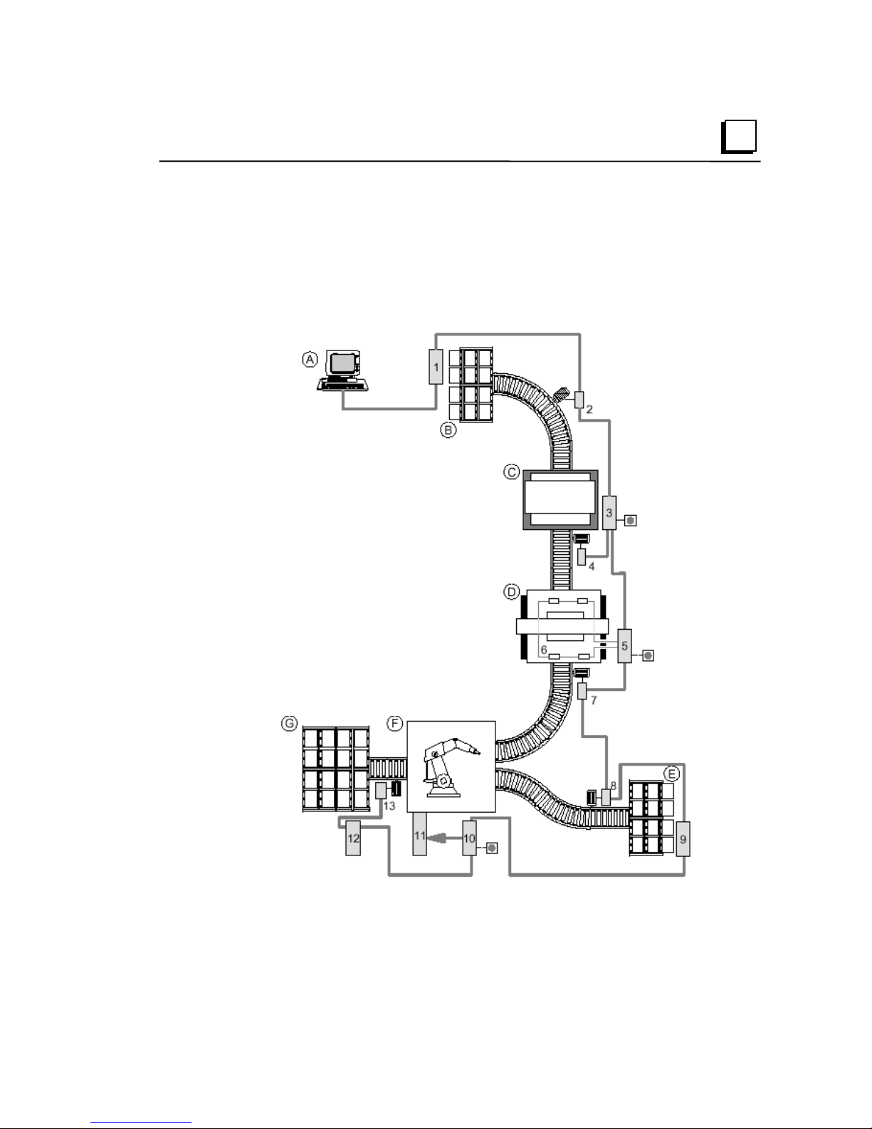
Example Plant
The following example provides an illustration of how the VersaPoint I/O
System may be applied. This example highlights the distributed nature of
the VersaPoint product line as well as its ability to fit a variety of difficult
applications within a single system.
1
GFK-1911B Chapter 1 Introduction 1-5
Page 16

1
Key:
A Plant control
B Material removal area 1
C Press
D Punching device
E Material removal area 2
F Welding robot
G Material area 3
1, 3, 5, 6, 9, 10, 12 VersaPoint™ stations
2, 4, 7, 8,13 Motor starter
11 Robot controller
Emergency stop switch
This example is a schematic diagram of a plant which is controlled by a host
computer.
VersaPoint station 1 modules control the removal of material from area 1.
The motor starter (2) is directly connected to the remote bus. This controls a
conveyor belt motor.
VersaPoint station 3 controls the press. As this machine must be
particularly well protected, an emergency stop switch has been integrated.
VersaPoint station 5 controls the punching device. Station 6 is connected to
station 5, and its modules monitor the status of the press. An emergency
stop switch has also been provided here.
Two motor starters are connected at points (7) and (8). They control
conveyor belt motors.
VersaPoint station 9 controls the removal of material from area 2.
A robot control system (11) is connected to the communications bus using
VersaPoint station 10. An emergency stop switch has also been connected
here.
VersaPoint station 12 controls the storage of material in area 3.
Motor starter 13 is directly connected to the remote bus and controls the
conveyor belt motor.
1-6 VersaPoint™ I/O System Profibus-DP NIU User’s Manual – August 2005 GFK-1911B
Page 17

Chapter
2
The Profibus NIU
This section describes the Profibus Network Interface Unit module IC220PBI002.
▪ The Profibus System
▪ Typical Profibus-DP VersaPoint I/O Station
▪ Structure of a VersaPoint I/O Station
▪ The Profibus-DP Network Interface Unit
▪ Features
▪ Items Used with the NIU
▪ Ordering Information
▪ Connectors on the NIU
▪ Profibus Connector
▪ Power Connector
▪ DIP Switches on the NIU
▪ LEDs on the NIU
▪ Diagnostics
▪ NIU Specifications
GFK-1911B 2-1
Page 18
2
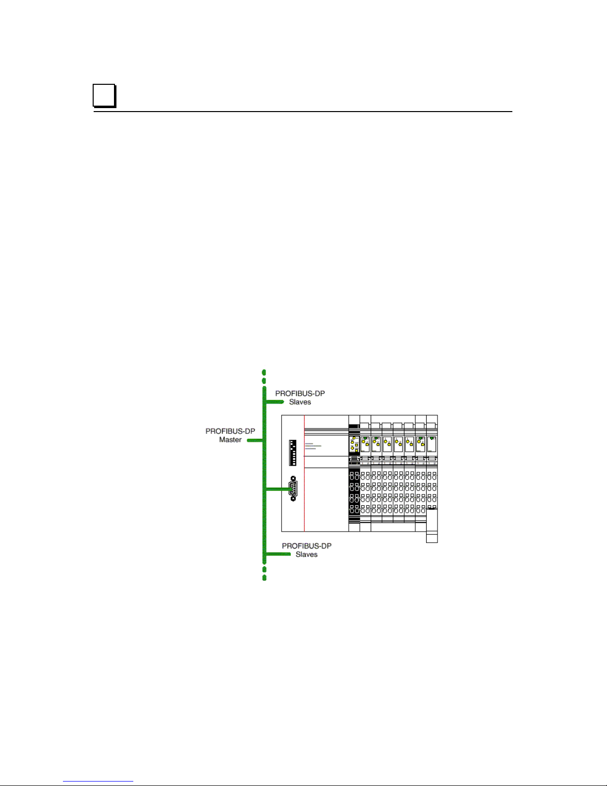
The Profibus System
Profibus is a serial bus system for data transmission between control systems and
distributed input and output modules, to which sensors and actuators are
connected.
Profibus has a star tree structure. In the Profibus topology the single bus devices
can be differentiated by means of their addressing. The communication profiles
determine how the devices transmit their data via the bus.
Profibus DP is normally a single master system. It is designed for easy
transmission of input and output data and specifically designed for communication
between automation systems and the distributed I/O devices.
Typical Profibus-DP VersaPoint I/O Station
A set of interconnected VersaPoint I/O modules can be selected to suit the
application, and connected as a slave on a Profibus-DP network. The interface
between the network and the modules is a VersaPoint Profibus-DP Network
Interface Unit (NIU) module.
The intelligent wiring method used in the VersaPoint modules allows I/O stations
to be constructed easily and quickly. Normally, it is only necessary for the power
supply units integrated in the Profibus NIU to be supplied with 24VDC on the input
side. They generate the operating voltage required for the NIU itself and for the
connected VersaPoint I/O modules.
2-2 VersaPoint™ I/O System Profibus-DP NIU User’s Manual – August 2005 GFK-1911B
Page 19
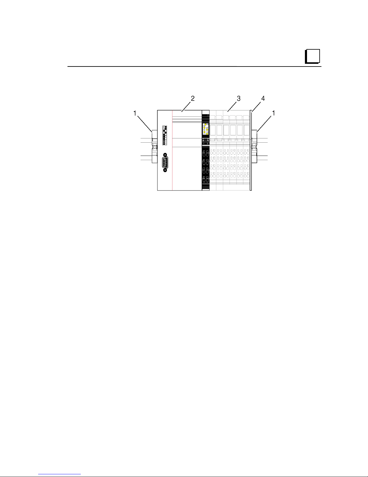
Structure of a VersaPoint I/O Station
2
A VersaPoint station with a Profibus NIU consists of:
– (1) End clamps (part number IC220ACC313, supplied with the NIU)
– (2) Profibus-DP Network Interface Unit
– (3) Modules appropriate to the application
– (4) End plate (supplied with the NIU)
GFK-1911B Chapter 2 The Profibus NIU 2-3
Page 20
2
The Profibus-DP Network Interface Unit
The VersaPoint ™ Profibus-DP Network Interface Unit (NIU), IC220PBI002, is the
link between Profibus-DP and the VersaPoint station. This module is an enhanced
version of the earlier Profibus-DP Network Interface Unit module IC220PBI001,
which it replaces. Differences between the two versions are explained below.
Features
The Profibus-DP Network Interface Unit has the following properties:
– A maximum of 63 VersaPoint I/O modules can be connected to Profibus DP
by simply plugging them in side by side next to the NIU. The NIU and the
VersaPoint modules create a station. Check chapter 5 to verify power
consumption.
– The sum of all input and output data can be up to 176 bytes per station for
module IC220PBI002 with its DIP switch 8 in the ON position. The maximum
is 184 bytes per station with DIP switch 8 in the OFF position. The maximum
for module IC220PBI001 is 184 bytes.
– The NIU can be used at a baud rate of 9.6 kbps for Profibus DP with a
maximum total expansion of 1200m (3937ft) or at baud rate of 12mbps with a
maximum of 100m (328 ft). The NIU automatically adjusts to the speed
specified by the Profibus master.
– Model IC220PBI002 also provides:
– DP/V1for Class 1 and Class 2 masters.
– Acyclic communications with modules such as RS-232 modules in the
process data channel.
– Fail-safe values
– Acknowledgement of I/O errors from the user program.
– Adaptation of the high byte/low byte format in 16-channel input and output
modules.
2-4 VersaPoint™ I/O System Profibus-DP NIU User’s Manual – August 2005 GFK-1911B
Page 21

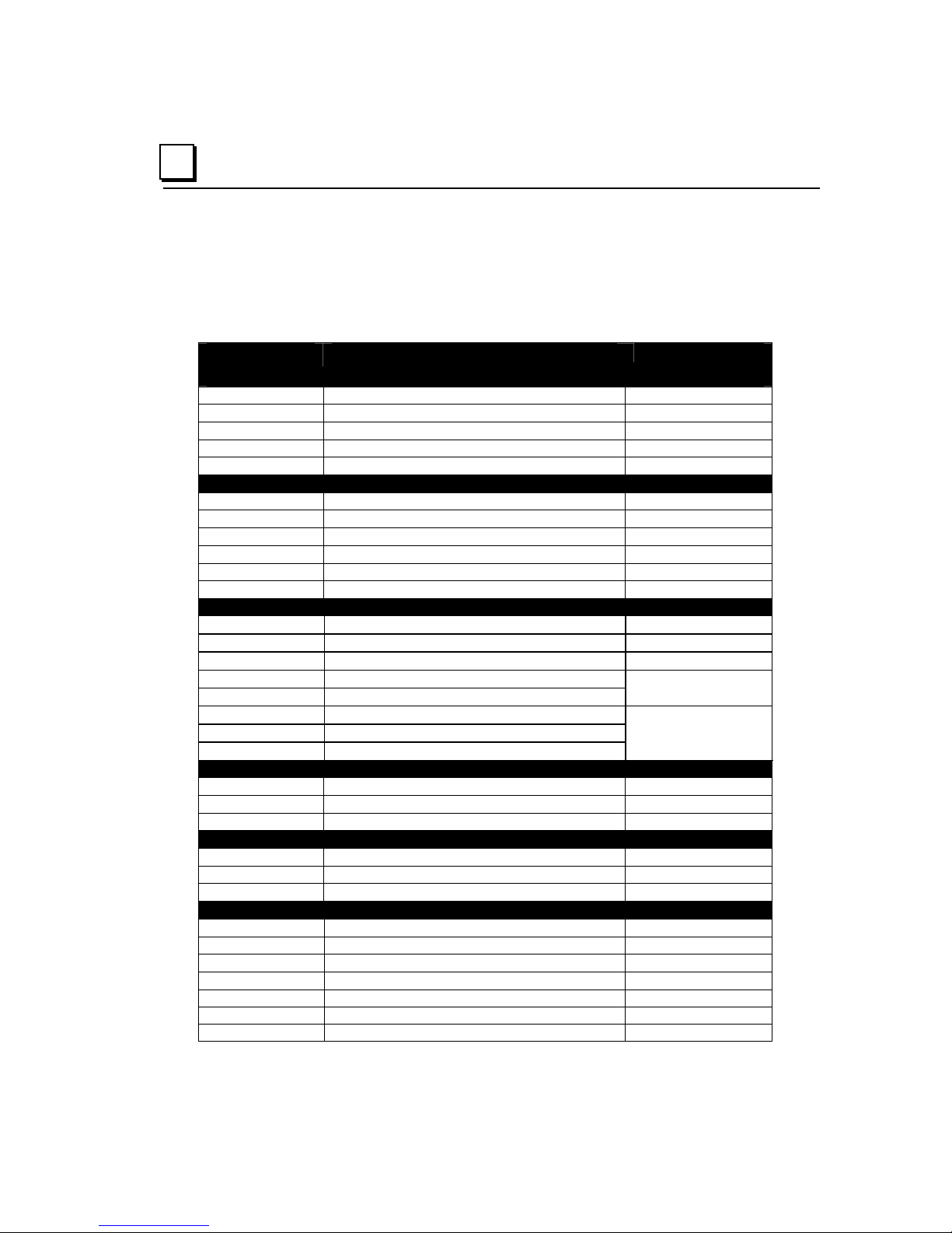
Comparison of Features
The table below compares features of module IC220PBI02 in DP/V1 mode or
DP/V0 mode (as selected with DIP switch 8) with the features of module
IC220PBI001.
2
Feature IC220PBI002 in
DP/V1 mode
PCP module operation x x -
DPV1 Read and DP/V1 Write support
(acyclic communication) Class 1 and
Class 2 masters
Communication with PCP modules
via normal process data (DP/VO)
Byte rotation for 16-point input and
output modules for adaptation to the
control system format
Byte rotation for 32-point input and
output modules
Acknowledgement of bus stops x x -
Acknowledgement of I/O errors x x -
Stop response can be set with DIP
switch
Stop response can be set with
parameter telegram
Assignable station ID firmware rev. B
Failsafe values even without
connection to the PLC
Improved I/O diagnostics during
startup
x - -
x x -
x x -
firmware rev. B
or later
- - x
x x -
or later
firmware rev. B
or later
firmware rev. B
or later
IC220PBO002
in DP/V0 mode
firmware rev. B
or later
- -
- -
- -
IC220PB001
-
GFK-1911B Chapter 2 The Profibus NIU 2-5
Page 22
2
Items Used with the NIU
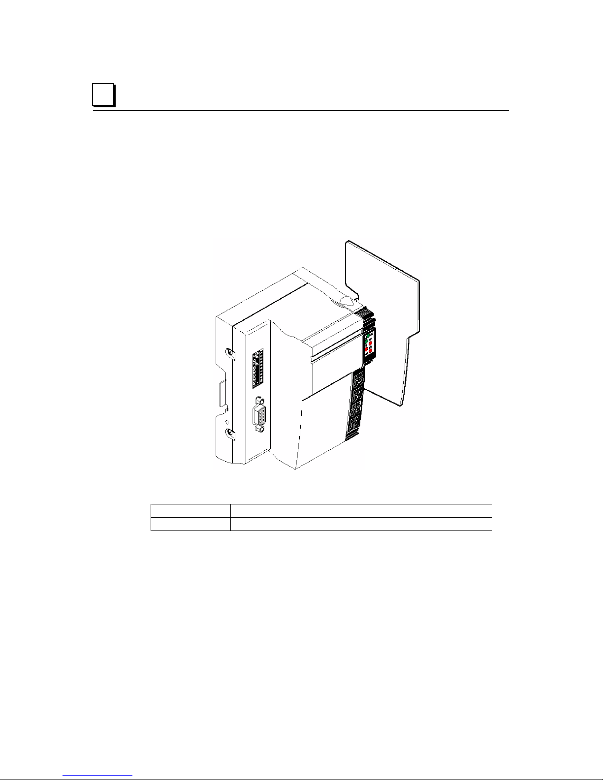
The Profibus NIU comes with an end plate, the latest GSD file, and one set of end
clamps.
The end plate is installed at the end of the VersaPoint station, after the last
module. It protects the station from electrostatic discharge and the user from
dangerous voltage.
The power connector is ordered separately. See the ordering information below.
Ordering Information
IC220PBI002 Profibus Network Interface Unit (replaces model IC220PBI001)
IC220TBK087 Power connector (quantity 10)
2-6 VersaPoint™ I/O System Profibus-DP NIU User’s Manual – August 2005 GFK-1911B
Page 23
Connectors on the NIU
Profibus Connector
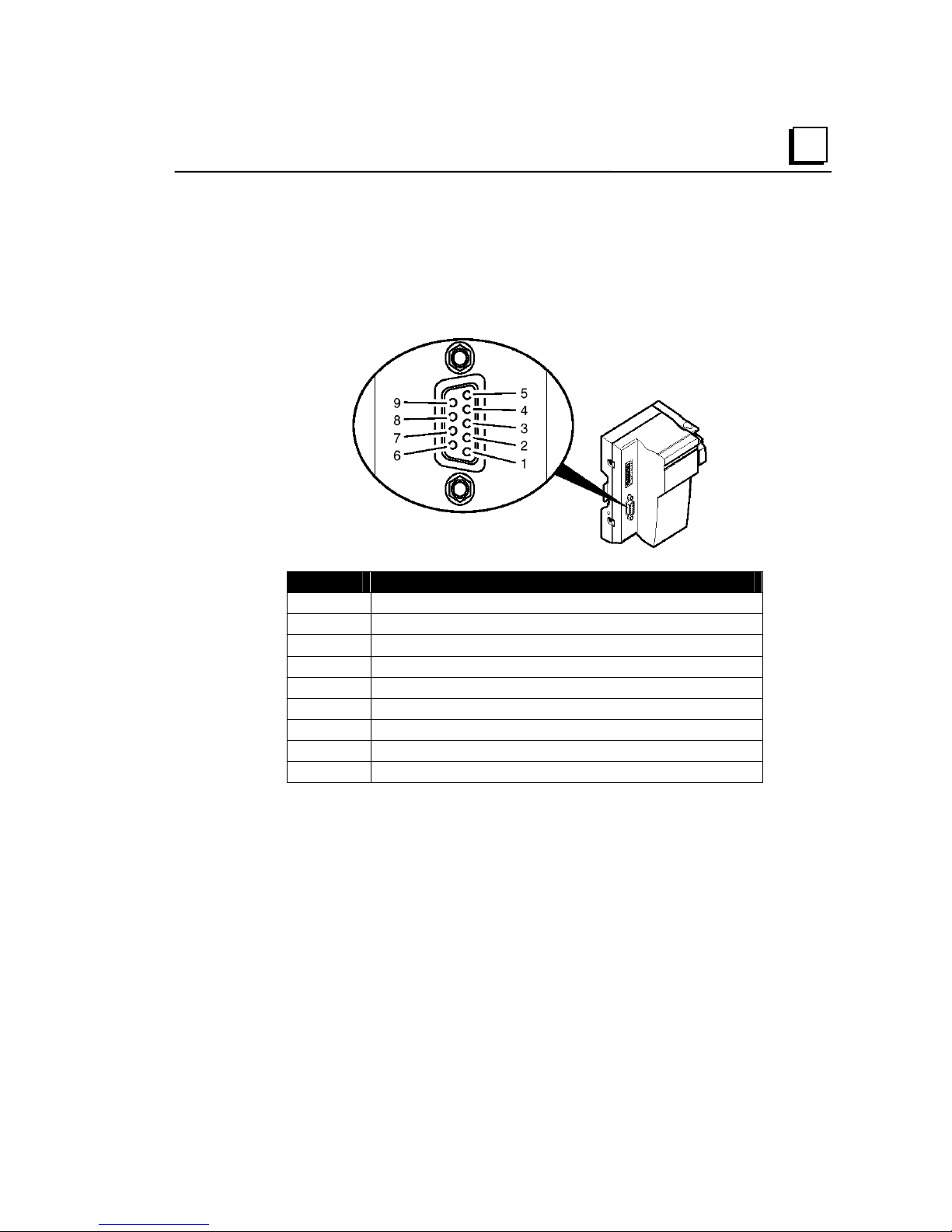
A 9-position, D-SUB connector connects the NIU to the Profibus cable.
2
Pin Assignment
1 Reserved
2 Reserved
3 RxD/TxD-P (+ receive/send data), cable B
4 CNTR-P (control signal for repeater), direction control
5 DGND (reference potential up to 5 V)
6 VP (supply voltage +5 V for terminal resistors)
7 Reserved
8 RxD/TxD-N (– receive/send data), cable A
9 Reserved
Line Terminal Resistors
Since Profibus is a serial bus system in a star-tree structure, the individual
branches must be terminated with a terminal resistor. The NIU does not have an
integrated resistor of this type. Many Profibus connectors are available with an
integrated, switchable resistor. Please contact your GE Intelligent Platforms
dist
ributor to determine availability.
GFK-1911B Chapter 2 The Profibus NIU 2-7
Page 24
2
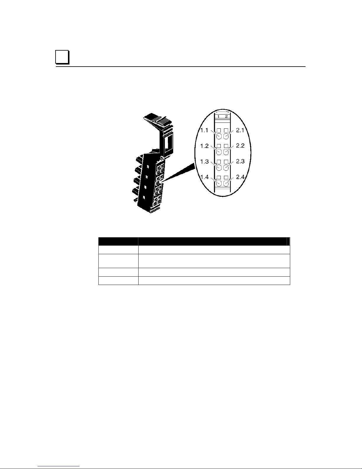
Power Connector
A power connector (IC220TBK087), ordered separately, is used to make power
and ground connections to the NIU.
Pin assignments for this connector are listed below:
Assignment of the NIU terminal points
Terminal Assignment
1.1, 2.1
1.2, 2.2
1.3, 2.3
1.4, 2.4
Segment supply (+24VDC)
Main supply, NIU supply, communications power and
interface supply (+24VDC)
Reference potential
Functional earth ground (FE)
NIU Power
The NIU acts as a power terminal, supplying the logic and module power for some
or all of the of the I/O modules in the station, as well as the sensors and actuators.
Some stations will also use additional power/segment terminals, depending on the
needs of the application. See chapter 5 for additional details.
2-8 VersaPoint™ I/O System Profibus-DP NIU User’s Manual – August 2005 GFK-1911B
Page 25
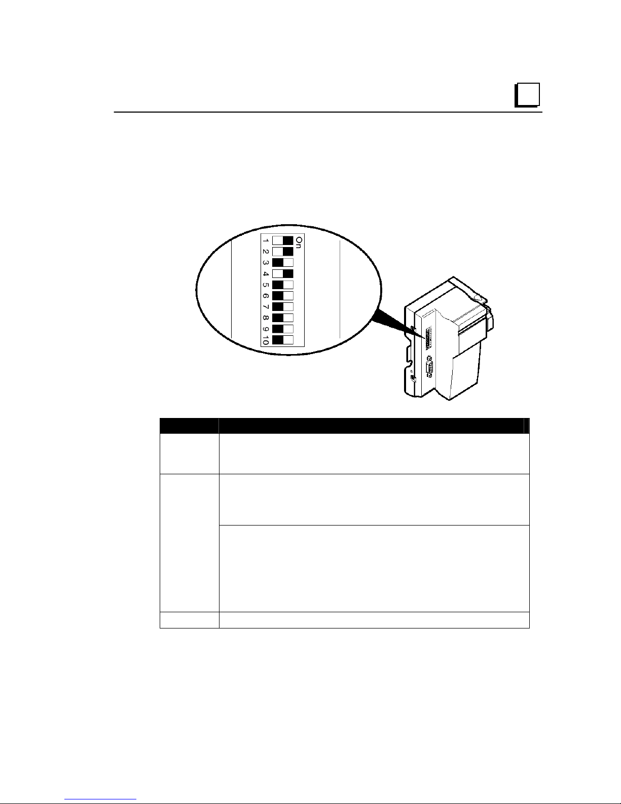
DIP Switches on the NIU
The 10-position DIP switch on the NIU module is used to set the Profibus address.
In addition, switch 8 can be used to select the operating mode of Profibus NIU
IC220PBI002. For model PBI001, the same switch specifies the error response of
the NIU.
2
Switches Meaning
1 to 7 Profibus Address in binary format (= 0 to 127 in decimal format)
0
) and
6
).
8
9 to 10
Switch 1 defines the least significant bit (2
switch 7 defines the most significant bit (2
For Module IC220PBI002: Sets the operating mode. With this switch in
the Off position (the default), this module can directly replace module
version IC220PBI001.
With this switch in the On position, this module operates in DP/V1 mode.
For Module IC220PBI001: Behavior if a data error occurs in the station
(local bus error):
ON = data transmission is stopped after a number of attempts.
OFF = the station constantly attempts to start data transmission.
If DIP switch 8 is in the ON position, a POWER DOWN/POWER UP must
be executed on the NIU so that it will restart. There is no automatic
restart after the error has been removed.
Reserved, both switches must be in the OFF position.
GFK-1911B Chapter 2 The Profibus NIU 2-9
Page 26
2
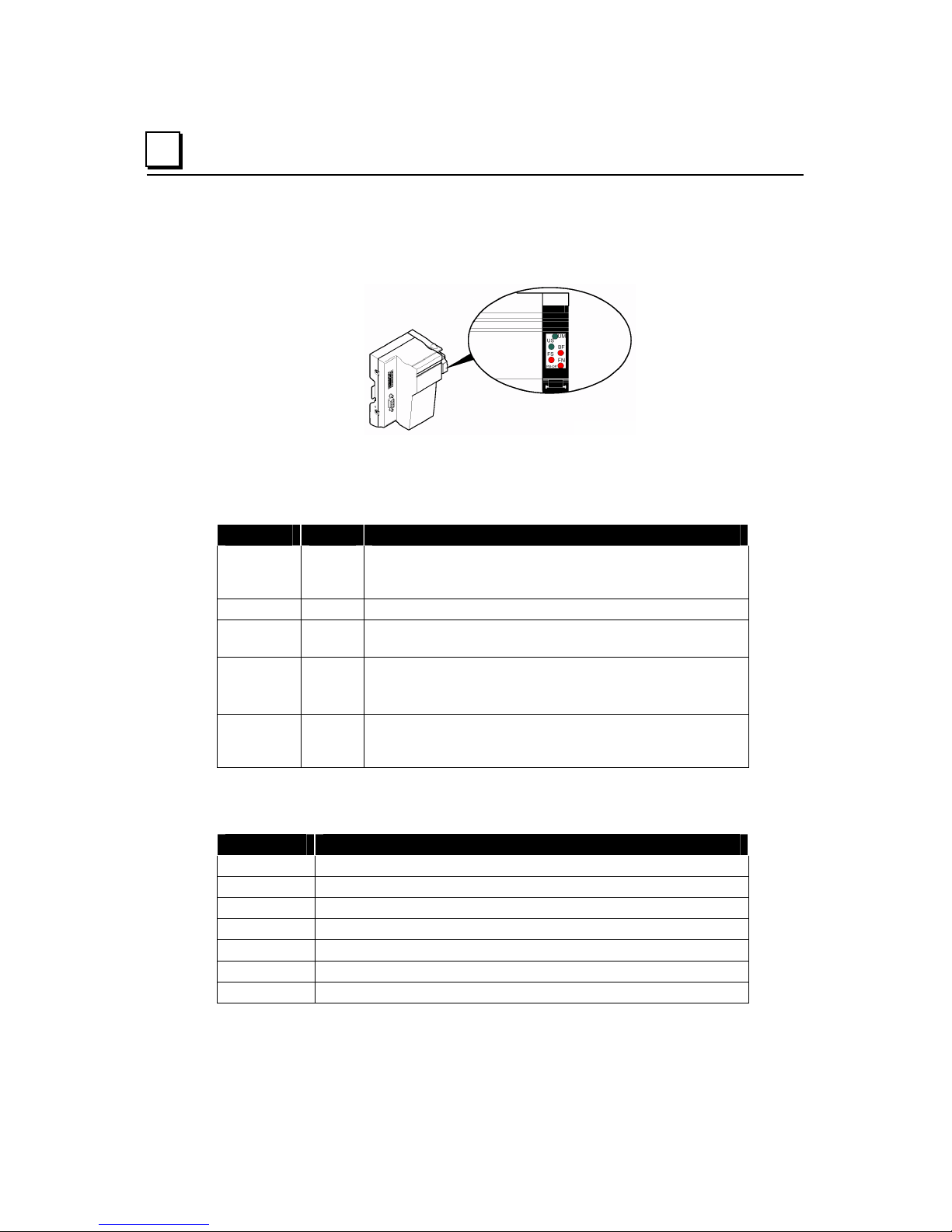
LEDS on the NIU
The diagnostic LEDs on the NIU indicate the type and location of errors.
The module is functioning correctly if all of the green LEDs are on.
Once errors have been removed, the indicators immediately display the current
status.
NIU LED Color Meaning
UM Green On = supply voltage in the main circuit for the NIU,
communications power and interfaces present. Off = main
circuit supply not present.
US Green On = 24 V segment circuit supply present
BF Red On = No communication on Profibus. Off = no error.
Flashing = PLC stopped, outputs default to safe values.
FS Red Defines the function of the FN LED:
FS ON: FN indicates the type of error.
FS OFF: FN indicates the error number
FN Red Off = no error. If flashing, the number of pulses indicates
the type of error or the error number, depending on
whether FS is on or not
Diagnostics
The NIU provides the following standard Profibus and device-related diagnostics.
Error Type Meaning
1 Parameter error on Profibus (SET_PRM telegram)
2 Configuration error on Profibus (CHK_CFG telegram)
3 Configuration error in the station
4 Error within the station
5 Module error
6 Parameter error on local bus
7 EEPROM error
2-10 VersaPoint™ I/O System Profibus-DP NIU User’s Manual – August 2005 GFK-1911B
Page 27

DPV1 Communications for Profibus NIU IC220PBI002
If the DP/V1 communications features of Profibus NIU IC220PBI002 are enabled
by configuration and if DIP switch 8 on the module is set to the On position, the
NIU supports enhanced DP/V1 communications with the master.
DP/V1 expands the cyclic data exchange function according to IEC 61158 to
include acyclic services. This makes it easy to operate even complex devices.
The Profibus NIU prepares the data records, which are sent via DP/V1 from the
master, and provides them to the specified modules in the I/O Station. The NIU
converts data from the modules into DP/V1 telegrams for the Profibus master.
Masters with DP/V1 ability include the PACSystems RX3i Profibus Master Module,
IC695PBM300, and the Series 90-30 CPU model IC693CPU366. Both of these
masters can use three types of COMMREQ (Communications Request) functions
in the application program to communicate with the Profibus NIU:
DPV1 Read Request Performs a DPV1 read request from a slave device
(such as the Profibus NIU).
DPV1 Write Request Performs a DPV1 write request to a slave device.
DPV1 Alarm Request Acknowledges a DPV1 alarm request.
2
GFK-1911B Chapter 2 The Profibus NIU 2-11
Page 28

2
NIU Specifications
General
Housing dimensions
(width x height x depth)
Degree of protection IP 20 according to IEC 60529
Class of protection Class 3 according to VDE 0106, IEC 60536
System Information
Number of devices per station 63, maximum
Sum of all I/O data per station,
maximum
Maximum NIU current for supplying
the I/O module logic
Maximum additional current for
supplying the analog terminals
Profibus-DP Interface Copper cable (RS-485), connected via SUB-D
91mm x 120mm x 71.5mm
(2.874in. x 4.724in. x 2.795in.)
176 bytes for IC220PBI002 in DP/V1 mode.
184 bytes for IC220PBI001, or for PBI002 with
DIP switch 8 set for operation in PBI001 mode
2A at UL
0.5A at U
shield connector; supply electrically isolated,
shielding directly connected with functional earth
ground.
ANA
2-12 VersaPoint™ I/O System Profibus-DP NIU User’s Manual – August 2005 GFK-1911B
Page 29

Chapter
3
VersaPoint Modules
This chapter describes the parts and dimensions of VersaPoint modules.
▪ Modules in a VersaPoint Station
▪ Parts of a VersaPoint Module
▪ The Electronics Base
▪ Diagnostics and Status Indicators
▪ Connectors
▪ Module Labeling
▪ Module Dimensions
GFK-1911B 3-1
Page 30
3
Modules in a VersaPoint Station
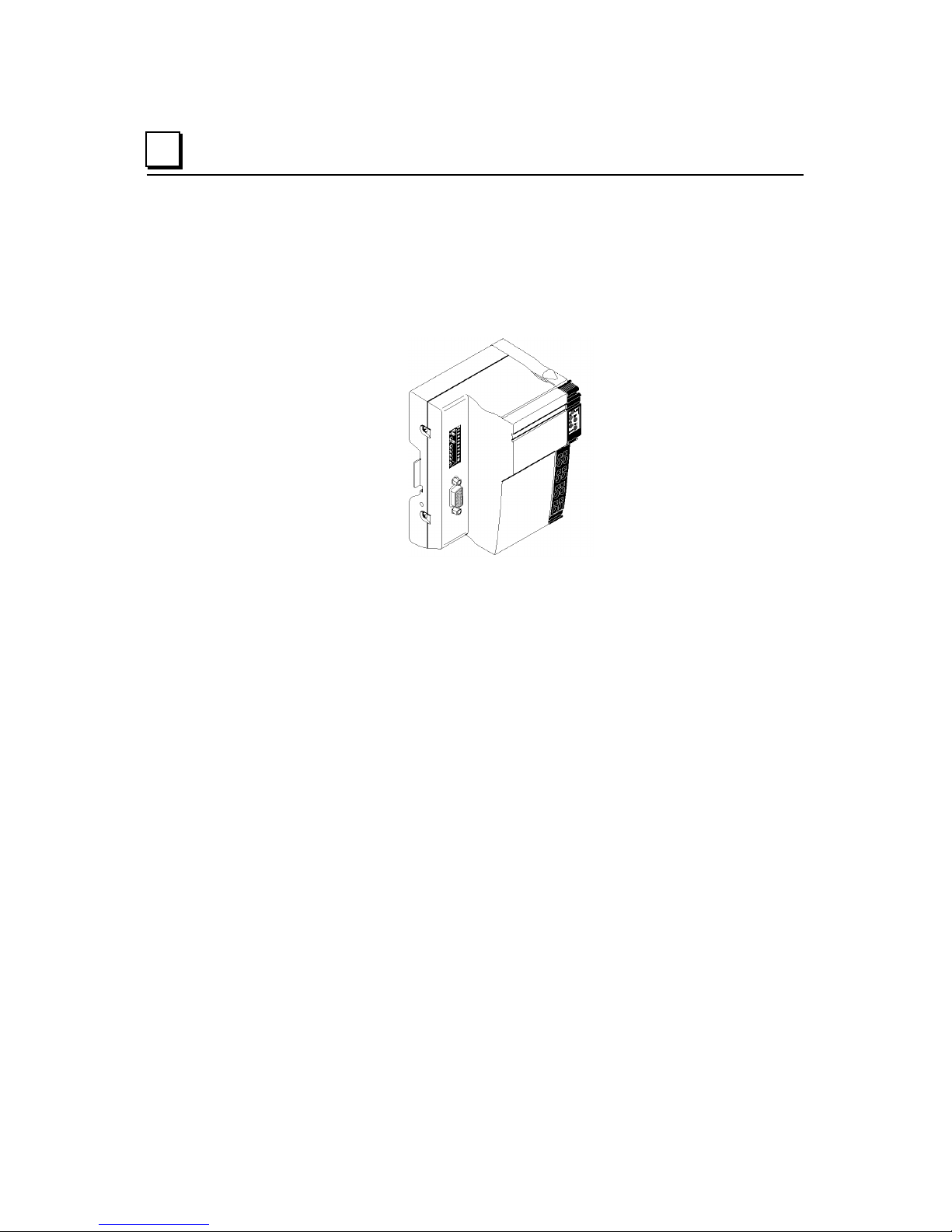
A VersaPoint I/O Station begins with a Network Interface Unit (NIU). The
NIU module is the first module on the DIN rail, at the left end of the I/O
Station. It is shown here with the required grounding to the DIN rail. See
chapter 2 for more information about the Profibus-DP Network Interface
Unit. The NIU performs all the data-handling and communications functions
for the I/O Station.
The rest of the station is made up of a group of I/O modules that can be
selected to exactly fit the needs of the application.
3-2 VersaPoint™ I/O System Profibus-DP NIU User’s Manual – August 2005 GFK-1911B
Page 31

Input/Output Modules
Many different types of I/O modules are available. This enables you to build
the station in a modular way so that it meets the application’s requirements.
Example of a digital input module: IC220MDL642
3
Terminal Points
Depending on the module, input/output modules have terminal points to
accommodate 2-, 3-, and 4-wire sensors or actuators. Connections are
made to Terminal Strips, which are ordered separately.
Protection
For output modules, surge voltage protection is provided by a fuse in the
Power Terminal module, or by an external fuse. The value of the fuse must
be such that the maximum load current is not exceeded. For the maximum
permissible load current of an I/O module please refer to the module’s data
sheet.
LEDs
The diagnostic and status indicators on I/O modules provide information on
the status of inputs and outputs.
GFK-1911B Chapter 3 VersaPoint Modules 3-3
Page 32

3
Interfacing to Functional Earth Ground (FE)
There is no interfacing to functional earth ground (FE) in the module, i.e. no
direct connection is made with FE when the module is mounted on a
grounded DIN rail.
Grounding
A module is grounded via the voltage jumper FE when snapping it onto the
previous module. Additional I/O module grounding is not required.
Electrical Isolation
Electrical isolation is not provided by VersaPoint I/O modules. A Power
Terminal module must be used for this purpose.
Voltage Ranges
Low-level signal terminals are available for different voltage ranges. To
utilize different voltage ranges within a station, a new power terminal must
be used for each range.
Power Losses for I/O Modules
Power Loss of the Electronics
The electronics power loss of an I/O module can be calculated following the
formula in the module’s datasheet. The power loss of the module must not
exceed the power loss of the housing.
Power Loss of the Housing
The power loss of the housing indicates the maximum power loss allowed.
The maximum power loss is indicated in the module’s datasheet. This power
loss can be dependent or independent of the ambient temperature. If the
power loss of the housing depends on the ambient temperature, a
permissible operating temperature range can be calculated using the
formula in the module's datasheet.
Permissible Operating Temperature Range
Depending on the power loss of the housing and the power loss of the
electronics at a certain current, the temperature up to which the module can
be operated with this current can be calculated. Please see the module
datasheets for specific information.
See appendix C for example calculations.
3-4 VersaPoint™ I/O System Profibus-DP NIU User’s Manual – August 2005 GFK-1911B
Page 33

Analog Modules
Shield
The connectors of analog modules have a special shield connection to
shield the cables.
Configuration
The modules for analog signals operate with a set of default parameters
unless they are reconfigured for the application. Each module’s defaults are
listed in its datasheet.
Diagnostics for Analog Input Modules
3
Analog input modules have overrange recognition in all measuring ranges.
Open circuit diagnostics are also available for some analog input modules. If
extended diagnostics are available for a specific module, they are listed in
the module’s datasheet. Analog error messages include:
▪ Under-range
▪ Open circuit
▪ Measured value invalid
▪ Configuration invalid
▪ Terminal defective
▪ Over-range.
GFK-1911B Chapter 3 VersaPoint Modules 3-5
Page 34

3
Power Terminal Modules
Power Terminal modules can be placed in an I/O Station to provide
additional power, to electrically isolate different circuits, or to create areas
with different voltages (ie: 24VDC versus 120VAC) within a station. Multiple
Power Terminal modules can be used in an I/O station.
A Power Terminal module supplies voltage for both the main circuit and the
segment circuit. See chapter 5 for more details.
Example: 24VDC Power Terminal
The main power circuit should be protected. If a protected Power Terminal
(IC220PWR002 or PWR003) is not used, the 24V supply must be externally
protected.
3-6 VersaPoint™ I/O System Profibus-DP NIU User’s Manual – August 2005 GFK-1911B
Page 35

Segment Terminal Modules
Segment Terminal modules can be used to create a segment circuit within
the main circuit. The segment circuit allows the separate supply of power
outputs (e.g., motor contactors), digital actuators, and digital sensors. With a
segment terminal you can also control the segment circuit and switch it on
or off, e.g., using emergency stop loops. Segment Terminal modules can
only be used with 24V power.
3
Segment Terminals do NOT provide electrical isolation. A Power Terminal
module must be used for that purpose.
Segment terminals can only be used with 24V power.
The connection between the main circuit and the segment / auxiliary supply
requires a jumper wire or external switch. Segment terminals have terminal
points for the connection of a jumper or switch. When using a standard
segment terminal, (IC220PWR011), the segment circuit is not protected!
The 24V supply must be externally protected. See "Power Terminals".
Segment terminals with internal fuse protection (IC220PWR012, 013, and
014) are also available.
GFK-1911B Chapter 3 VersaPoint Modules 3-7
Page 36

3
Parts of a VersaPoint Module
A VersaPoint I/O or power module consists of an electronics base and plugin connector.
3-8 VersaPoint™ I/O System Profibus-DP NIU User’s Manual – August 2005 GFK-1911B
Page 37

The Electronics Base
The electronics base holds the entire electronics for the VersaPoint module
and the voltage and data routing.
As all the modules are snapped onto the DIN rail, there is a secure interface
between the modules. Voltage and current for station operation are routed
through the jumpers on each module, which are indicated in the following
illustration. This functionality is explained in detail in chapter 5.
3
Built-in snapping mechanisms on the electronics base make it easy to install
on the DIN rail without the use of tools. (Please see the installation
instructions in chapter 4).
GFK-1911B Chapter 3 VersaPoint Modules 3-9
Page 38

3
Diagnostic and Status Indicators
All modules have diagnostic and status indicators for rapid local error
diagnostics.
The diagnostic indicators (red/green) indicate the status of the modules. A
module is operating normally if all its Diagnostic (D) LEDs are solid green.
The status indicators (yellow) display the status of the relevant
inputs/outputs for the connected device. LEDs are described in detail in
chapter 6.
Module Color Coding
The area surrounding each module's LEDs is color-coded to provide an
indication of the module's function. The following table explains this colorcoding.
Color Function
Gray Analog
Blue Digital - DC
Red Special function
Orange Digital mixed
Black Power terminal / segment terminal / NIU
3-10 VersaPoint™ I/O System Profibus-DP NIU User’s Manual – August 2005 GFK-1911B
Page 39

Status LEDs and I/O Points
The illustration below shows the relationship between the status LEDs on a
module and the module inputs or outputs.
3
In general, an I/O module's status LEDs appear over their associated
terminals. In cases where two I/O points are terminated in the same column
(for 4 and 16 point modules), the LED's relative position (top or bottom)
indicates the I/O point it is associated with.
For a single-width module with 4 inputs or outputs (middle module in the
illustration above), the LEDs and terminal points are associated as follows:
LED 1 Terminal point 1.1
LED 2 Terminal point 2.1
LED 3 Terminal point 1.4
LED 4 Terminal point 2.4
On the four-slot module, LED 2 on slot 4 is indicated. The LED belongs to
input 14 on terminal point 4/2.1 (slot 4 / terminal point 2.1)
GFK-1911B Chapter 3 VersaPoint Modules 3-11
Page 40

3
Connectors
The connection of the I/O or supply voltages is made by using a connector
that can be plugged on or off the modules.
Connector Types
The following connector types are available:
(1) Standard connector (IC220TBK082, 085, 087)
The standard connector is used for the connection of two signals in 4-wire
format (e.g., digital input/output signals). The standard connector housing is
also used for power and segment terminals and relay terminals, although
the types are NOT interchangeable.
(2 )Shield connector (IC220TBK061)
This connector is used for signals connected using shielded cables (e.g.,
analog I/O signals, high-speed counter inputs, network cable). The FE or
shielding is connected by a shield clamp.
(3) Extended, connector (IC220TBK122, TBK123)
This connector is used for the connection of four signals in 3-wire format
(e.g., digital input/output signals).
Regardless of the width of the electronics base, the connectors are provided
with a standard width. Wider modules may require multiple connectors.
Connector Identification
Connectors have terminal points that are color coded corresponding to their
functions:
Color Terminal point signal
Red +
Blue –
Green Functional earth ground
3-12 VersaPoint™ I/O System Profibus-DP NIU User’s Manual – August 2005 GFK-1911B
Page 41

3
Internal Structure of the Connector
A Standard connector (IC220TBK082, 085)
B Connector for power and segment terminals (IC220TBK087)
C Shield connector (IC220TBK061) for analog modules
D Extended connector (IC220TBK122, TBK123)
The dark lines shown on connectors B and D above indicate jumper
connections. These jumpers are internal to the connectors.
The shield connector is jumpered through the shield connection. All other
connectors are jumpered through module point connection.
To avoid a malfunction, only snap a suitable connector on a module that is
appropriate for this connector. Refer to the module-specific data sheet to
select the correct connectors.
A supply connector must not be placed on a module that is to be used
with an extended connector. This will cause a short circuit between
two signal module points (1.4 - 2.4).
Place only supply connectors on supply modules. Do not use the
standard connectors! When the terminal points are jumpered in the
supply connector, power is carried through the jumpering in the
connector and not through the printed circuit board of the module.
GFK-1911B Chapter 3 VersaPoint Modules 3-13
Page 42

3
Module Dimensions
The module dimensions are determined by the dimensions of the electronics
base and the dimensions of the connector.
When a connector is plugged in, each module depth is 71.5mm (2.795 in.).
The height of the module depends on the connector used.
Single Housing Double Housing Wide Housing Depth, All
Connector Dimensions
Key:
A. Standard connector (IC220TBK082, IC220TBK085, IC220TBK087)
B. Shield connector (IC220TBK061)
C. Extended connector (IC220TBK122, IC220TBK123)
The depth of the connector does not influence the overall depth of the
module.
3-14 VersaPoint™ I/O System Profibus-DP NIU User’s Manual – August 2005 GFK-1911B
Page 43

Chapter
4
Installation
This chapter describes basic VersaPoint module installation and cable
connections. Please refer to chapter 5 for more information about power
connections for the I/O Station.
▪ Parts of a VersaPoint I/O Station
▪ Planning module sequence in the I/O Station
▪ Power for the station
▪ Setting the NIU switches
▪ Keying
▪ Installing modules on the DIN rail
▪ Removing modules
▪ Connecting unshielded cables
▪ Connecting shielded cables
▪ Grounding
▪ Connecting the Profibus cable at the NIU
▪ Connecting power at the NIU
▪ Replacing power and segment terminal fuses
▪ Connecting sensors and actuators
▪ Module labeling
GFK-1911B 4-
1
Page 44

4
Parts of a VersaPoint I/O Station
A VersaPoint station with a Profibus Network Interface Unit consists of:
– (1) End Clamps (supplied with NIU)
– (2) Profibus NIU
– (3) Modules appropriate to the application
– (4) End Plate (supplied with the NIU)
Mount modules side by side on a 35mm (1.378in.) standard DIN rail. No tools are
required.
Do not set up the station while the power is connected. Before setting up a
VersaPoint station or inserting a module, be sure the entire station is disconnected
from the power. Be sure the entire station is reassembled before switching power
on.
End Plate
The VersaPoint I/O Station must be terminated using the end plate that is supplied
with the Network Interface Unit module. The end plate does not have an electrical
function. It protects the station from ESD pulses and the user from dangerous
voltages.
End Clamps
Install end clamps on both ends of the station to hold it in place on the DIN rail.
End clamps are supplied with the NIU. If additional clamps are required, they are
available as GE
4-2 VersaPoint™ I/O System Profibus-DP NIU User’s Manual – August 2005 GFK-1911B
Intelligent Platforms part num
ber IC220ACC313.
Page 45

Planning Module Sequence in the I/O Station
The NIU is the first module in the station. The sequence of the other modules
should be planned carefully. Within a main circuit, place the I/O modules with the
highest current consumption (U
) first. For example:
S
▪ Discrete output modules with 8-slot housings
▪ Discrete output modules with 2-slot housings
▪ Discrete input modules with 8-slot housings
▪ Discrete input modules with 2-slot housings
4
▪ Special-function modules
▪ Analog modules
This approach is advantageous in that the high supply current does not flow
through the entire main circuit.
Locations for Analog Modules
High current flowing through voltage jumpers UM and US increases the
temperature of the voltage jumpers and the inside of the module. Note the
following instructions to keep the current flowing through the voltage jumpers of
the analog modules as low as possible:
It is recommended that each analog module have a separate main circuit. If this is
not possible and it is necessary to use analog modules in a main circuit together
with other modules, place the analog modules at the end of the main circuit(to the
right of other modules).
This practice is particularly important for the thermocouple module IC220ALG630.
Internal module heating falsifies the temperature of the internal cold junction.
Therefore, position this module after all of the other modules to minimize the
current flowing through all voltage jumpers.
GFK-1911B Chapter 4 Installation 4-3
Page 46

4
Power for the Station
The Profibus NIU receives power from the Profibus connection. This Profibus
power supplies the NIU, and can also supply the logic and analog power for the
I/O Station. A station may also include one or more Power Terminal and Segment
Terminal modules. Power Terminal modules must be connected to external
power. Segment Terminal modules draw their power from the main supply within
the station, and are not connected to external power.
NIU
Power
Terminal
Segment
Terminal
Please see chapter 5 for more information about station power.
Voltage supplies are connected using unshielded cables as described previously.
4-4 VersaPoint™ I/O System Profibus-DP NIU User’s Manual – August 2005 GFK-1911B
Page 47

Electrical isolation
If electrical isolation is required between logic and I/O you must provide the NIU
supply U
If various electrically isolated areas are required within a VersaPoint station,
additional power terminals that draw their current from separate power supplies
must be used.
The correct method of providing and distributing power to the station depends on
the needs of the application. See chapter 5 for detailed information about power
sources and power distribution in the VersaPoint I/O station.
Use power supplies with safe isolation!
Use power supplies that ensure safe isolation between primary and secondary
circuit (according to EN 50178).
For additional voltage supply specifications refer to the data sheets of the NIUs
and power terminals.
Voltage supplies are connected using unshielded cables as described previously.
For the connector assignment of the supply voltage connections please refer to
the module-specific data sheets of NIU, power terminals, and segment terminals.
and the I/O supply US from separate power supplies.
M
4
Dangerous voltage!
When the power terminal is removed, the metal contacts are freely accessible.
With 120V or 230V power terminals, it should be assumed that dangerous voltage
is present. You must disconnect power to the station before removing a terminal!
If these instructions are not followed, there is a danger of damage to health
and danger of a life-threatening injury.
GFK-1911B Chapter 4 Installation 4-5
Page 48

4
Setting the NIU Switches
Configure the hardware using the 10-position DIP switch on the NIU module.
Switches Meaning
1 to 7 Profibus Address in binary format (= 0 to 127 in decimal format)
8
0
Switch 1 defines the least significant bit (2
switch 7 defines the most significant bit (2
For Module IC220PBI002: Sets the operating mode. With this switch in
the Off position, this module can directly replace module version
IC220PBI001.
With this switch in the On position, this module operates in DP/V1 mode.
The On position matches the NIU’s default configuration.
) and
6
).
For Module IC220PBI001: Behavior if a data error occurs in the station
(local bus error):
ON = data transmission is stopped after a number of attempts.
OFF = the station constantly attempts to start data transmission.
If DIP switch 8 is in the ON position, a POWER DOWN/POWER UP must
be executed on the NIU so that it will restart. There is no automatic
restart after the error has been removed.
9 to 10
4-6 VersaPoint™ I/O System Profibus-DP NIU User’s Manual – August 2005 GFK-1911B
Reserved, both switches must be in the OFF position.
Page 49

Keying Connectors and Modules
You can prevent the mismating of any connector by keying the base and the
connector using module keys (ordered separately, IC220ACC005 quantity 100).
4
A. Plug a coding key into the keyway in the base (1) and turn it away from the
small plate.
B. Use a pair of cutters to cut off the keying tab from the connector.
GFK-1911B Chapter 4 Installation 4-7
Page 50

4
Installing Modules on the DIN Rail
Mount modules side by side on a 35mm (1.378 in.) standard DIN rail.
▪ First, attach the electronics bases to the DIN rail by pushing the base straight-
in towards the rail (1).
Be sure that all featherkeys and keyways on adjacent modules are interlocked
(2). First, align the featherkey of the module with the keyway of the previous
module. Then, attach the new module to the DIN rail by pushing it straight in
toward the rail. Do not twist or pivot the module during installation; that may
damage the modules.
▪ Next, attach the Terminal Strip to the module.
First, place the front latch in the front snap-on mechanism (3).
Then pivot the top of the Terminal Strip towards the module until the back
latch snaps into place (4).
The keyways of a module do not continue on the Terminal Strip. When snapping
on an module, there must be no Terminal Strip on the left-hand side of the
module. If a Terminal Strip is present, remove it before installing the next module.
4-8 VersaPoint™ I/O System Profibus-DP NIU User’s Manual – August 2005 GFK-1911B
Page 51

Removing Modules
When removing a module, follow the steps shown below:
▪ If there is a module label present, remove it (A-1, below).
If the module has more than one Terminal Strip, all of the these must be
removed. The following describes how a single-slot module is removed.
4
Lift the Terminal Strip by pressing on the connector latch (A-2).
▪ Remove the Terminal Strip (B).
▪ Remove the left-adjacent and right-adjacent Terminal Strips of the neighboring
modules (C). This prevents the potential routing featherkeys and the
keyway/featherkey connection from being damaged and creates more space
for accessing the module.
▪ Press the release mechanism, and remove the module from the DIN rail by
pulling it straight back (D-2).
▪ To remove the NIU, the left end clamp must be removed first.
Replacing a Module
If you want to replace a module within the VersaPoint station, reverse the removal
procedure above.
GFK-1911B Chapter 4 Installation 4-9
Page 52

4
Connecting Unshielded Cables
Unshielded cables for I/O devices and supply voltages are connected using the
spring-clamp terminals. Signals up to 250VAC/DC and 5A with a conductor crosssection of 0.2mm
2
to 1.5mm2 (AWG24 – 16) can be connected.
For terminal assignments, please consult the appropriate module data sheet.
Follow these steps when wiring:
▪ Strip 8mm (0.3in.) off the cable. Module wiring is normally done without
ferrules. However, it is possible to use ferrules. If using ferrules, make sure
they are properly crimped.
▪ Push a screwdriver into the slot for the appropriate connection (#1 above) so
that you can plug the wire into the spring opening.
▪ Insert the wire (#2 above). Pull the screwdriver out of the opening. The wire is
clamped.
After installation, you should label the wires and Terminal Strips as described later
in this chapter.
4-10 VersaPoint™ I/O System Profibus-DP NIU User’s Manual – August 2005 GFK-1911B
Page 53

Connecting Shielded Cables
Observe the following when installing shielding:
▪ Strip the outer cable sheath to the desired length (#1a below). The appropriate
length depends on the connection position of the wires and whether there
should be a large or a small space between the connection point and the
shield connection.
4
▪ Shorten the braided shield to 15mm (0.6 in.) (#1 above).
▪ Fold the braided shield back over the outer sheath. (#2 above)
▪ Remove the protective foil.
▪ Strip 8mm (0.3in.) off the wires. (#2 above)
Connecting Shielded Cables to the Shielded Terminal Strip
▪ Open the shield connector (#3 above).
▪ Check the orientation of the shield clamp in the Shielded Terminal Strip and
change its position if necessary (see below for instructions).
▪ Place the cable with the folded braided shield in the shield connector. (#4
above)
GFK-1911B Chapter 4 Installation 4-11
Page 54

4
▪ Close the shield connector (#5 above).
▪ Fasten the screws for the shield connector using a screwdriver. (#6 above).
Repositioning the Shield Clamp
The shield clamp (2a, below) in the shield connector can be adjusted to
accommodate thin or thick cable. The shield connection is delivered with the
clamp positioned for the connection of thicker cables (#2 below). In that position,
the bend in the clamp faces away from the cable. For thinner cables the bend in
the clamp faces towards the cable (#6 below).
If you need to change the alignment of the shield clamp, proceed as shown below:
▪ Open the shield connector housing (#1).
▪ Remove the clamp (#3), turn the clamp according to the cross-section of the
cable (#4) and then reinsert the clamp. (#5)
4-12 VersaPoint™ I/O System Profibus-DP NIU User’s Manual – August 2005 GFK-1911B
Page 55

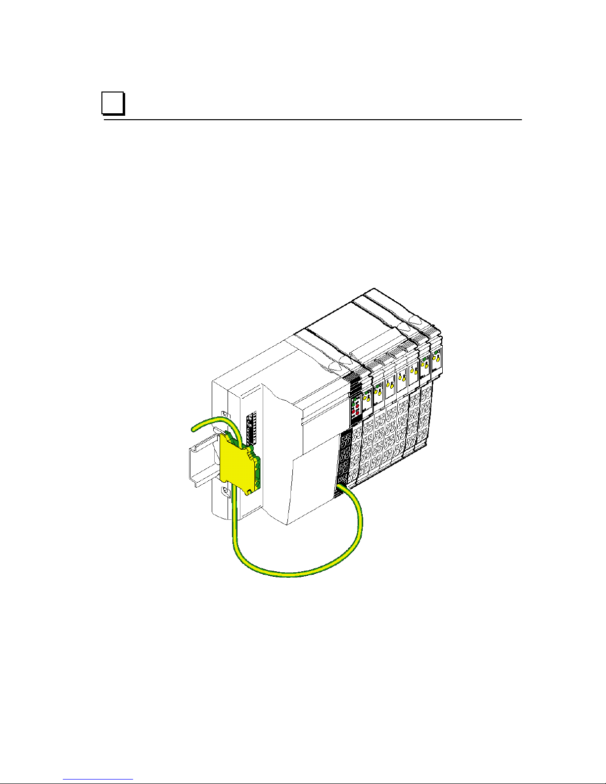
Grounding
4
All devices in a VersaPoint station must be grounded so that possible signal
interference is shielded and discharged to ground. A wire of at least 1.5mm
AWG) must be used for grounding.
Grounding the NIU and Power Modules
The NIU, power terminals, and segment terminals have an FE spring (metal clip)
on the bottom of the electronics base. These springs create an electric connection
to the DIN rail. VersaPoint I/O modules are automatically grounded via the FE
voltage jumper when they are connected to other modules. The FE voltage jumper
(functional earth ground) runs from the NIU through the entire VersaPoint station.
The function of FE is to discharge interference. It does not provide shock
protection.
Required Additional Grounding
To ensure a reliable ground connection even if the DIN rail is dirty or the metal clip
damaged, GE Intelligent Platforms rec
rail-mounted grounding terminal block, via the FE terminal point.
ommends grounding the NIU to a DIN
2
(16
GFK-1911B Chapter 4 Installation 4-13
Page 56

4
Installing the Profibus Cable
When laying the Profibus cable, note the following:
▪ Do not lay signal and bus cables parallel to power cables or in bundles with
power cables.
▪ Lay Profibus cables and cables with direct voltages > 60V and alternating
voltages > 25V in separate bundles or cable channels.
▪ Always lay signal cables in one channel, following the shortest route.
▪ Avoid extending the Profibus cables with connectors.
▪ Do not lay Profibus cables in bundles with telephone lines and cables leading
to potentially explosive areas.
▪ Avoid branch lines.
Refer to the following cable specifications, connector description, and instructions
for cable shielding and bus termination.
Profibus Cable Specifications
The proper cable for a Profibus network is a shielded twisted pair cable. Profibus
cable is available from Siemens parts distributors and sold as "Profibus Network
Cable". The twisted pair cable consists of a Green and a Red wire. Below are
some of the cable characteristics of Profibus cable.
Profibus Network Cable Siemens part # 6XV1-830
Profibus 9-pin Connector Siemens part # 6ES7972
Impedance 135 to 165 Ohms (3 to 20 MHz)
Capacity < 30 pF per meter
Resistance < 110 Ohms per Kilometer
Wire Gauge > 0.64 mm (0.025 inch)
Conductor Area > 0.34 mm2 (AWG 22)
For data rates up to 500 kbits/second, follow the stub recommendations in the
Profibus technical standard. At 1500 kbits/second the overall drop capacity should
be less than 0.2nF. Maximum length of the stub at 1500 kbits/second is 6.6
meters.
4-14 VersaPoint™ I/O System Profibus-DP NIU User’s Manual – August 2005 GFK-1911B
Page 57

)
)
The Profibus Cable Connector
Most Profibus devices, including the VersaPoint Network Interface Unit, provide
the Profibus standard female 9-pin D subminiature connectors. Cable connectors
are available from Siemens parts distributors as "Profibus 9-pin D connectors".
These connectors provide termination resistors and a switch on the connector to
enable/disable termination.
4
The connectors label the connections for the twisted pair as cable A and cable B.
The following table illustrates the proper assignment of wire to connector to pin to
signal.
Pin Signal
1, 2, 7, 9 Reserved
3 RxD/TxD-P (receive/transmit data +), cable B
4 CNTR-P (control signal for repeater), direction control
5 DGND (reference potential up to 5V)
6 VP (supply voltage +5V for termination resistors)
8 RxD/TxD-N (receive/transmt data -), cable A
Shielding the Profibus Cable
Cable shielding is recommended at higher baud rates. Cable shields must be
attached at each device via the connector shells.
When mounting the NIU in the cabinet, connect the cable shield of the connected
Profibus cable with a shield bus via cable clamps. Use an appropriate shield
clamp for this.
RxD/TxD-P (3)
DGND (5)
VP (6)
RxD/TxD-N (8)
Red (B
Green (A
RxD/TxD-P (3)
DGND (5)
VP (6)
RxD/TxD-N (8)
GFK-1911B Chapter 4 Installation 4-15
Page 58

4
Bus Termination
Termination resistors are needed, as defined in DIN 19245 Part 1 section 3.1.2.5.
Master Slave Slave Slave SlaveSlave
Termination Required
(Segment 1)
One terminator must be applied at each end of a network segment.
Master Slave Slave Slave SlaveSlave
Termination Required
(Segment 1)
Repeater
Termination Required
(Segment 2)
Generally, termination is provided in commercially-available Profibus standard
network connectors. Some connector vendors provide termination capability in
the connector and a switch on the connector to enable/disable termination. Some
connector vendors provide both terminated and unterminated connectors.
Important: For proper network termination, it is essential that the terminating
devices maintain power. Power is provided by the device on Pin 6 and Ground on
Pin 5. If power is lost to either terminating device, the network may not operate
correctly. Generally, the lone network master device is one of the terminating
devices. Therefore, a loss of power to the network master renders the network
inoperable anyway. The other terminating device may be a critical slave device
which must maintain power or a separately powered, stand-alone terminator.
These stand-alone devices are commercially available.
4-16 VersaPoint™ I/O System Profibus-DP NIU User’s Manual – August 2005 GFK-1911B
VP (6)
RxD/TxD-P (3)
RxD/TxD-N (8)
DGND (5)
Ru = 390 Ohms
Rt = 220 Ohms
Rd = 390 Ohms
Page 59

Connecting Power at the NIU
Terminal Assignment
1.1, 2.1
1.2, 2.2
1.3, 2.3
1.4, 2.4
Segment supply (+24VDC)
Main supply, NIU supply, communications power and
interface supply (+24VDC)
Reference potential
Functional earth ground (FE)
4
Providing the 24V Segment Supply (US ) at the NIU
You can supply/generate the segment voltage at the NIU or a Power Terminal
module. There are several ways of providing the segment voltage on the NIU:
1. You can provide the segment voltage separately on the terminal points 1.1/2.1
and 1.3/2.3 (GND) of the Power Terminal Strip.
2. You can jumper the connections 1.1/2.1 and 1.2/ 2.2 to ensure that the
segment circuit is supplied from the main circuit.
3. With a switch between the terminal points 1.1/ 2.1 and 1.2/2.2 you can create
a segment circuit (e.g., an emergency stop circuit).
CAUTION: To minimize heat generation, use both of the adjacent contacts to
provide the main voltage and to provide/tap the segment voltage.
Fusing for Short Circuit Protection
Both the segment supply US and the main supply UM have the same reference
potential. Therefore, an isolated voltage area on the I/O side cannot be created.
Both the main supply and the segment supply are protected against polarity
reversal and surge voltage.
CAUTION: The main supply and the segment supply integrated into the NIU
do not have short circuit protection. The user must provide short circuit
protection. The rating of the fuse must be such that the maximum
permissible load current is not exceeded.
GFK-1911B Chapter 4 Installation 4-17
Page 60

4
Replacing Power and Segment Terminal Fuses
For VersaPoint Power and Segment Terminal modules that have built-in fusing, if
a fuse is not present or defective, you must insert or exchange the fuse. Follow the
steps below to replace a fuse:
1. Lift the fuse lever (A).
2. Insert the screwdriver behind a metal contact of the fuse (B).
3. Carefully lift the metal contact of the fuse (C).
4. Carefully lift the fuse on one side and remove it by hand(D).
5. Insert a new fuse (E).
6. Push the fuse lever down again until it snaps into place with a click (F).
4-18 VersaPoint™ I/O System Profibus-DP NIU User’s Manual – August 2005 GFK-1911B
Page 61

Connecting Sensors and Actuators
Each module-specific data sheet indicates the appropriate Terminal Strip(s) for
that module.
Connecting Discrete Devices
VersaPoint discrete modules allow the connection of sensors and actuators in 2wire, 3-wire, or 4-wire technology (ability varies by module). A single Terminal
Strip can support the following connection methods:
– 2 sensors or actuators in 2-, 3-, or 4-wire technology
– 4 sensors or actuators in 2- or 3-wire technology
– 2 sensors or actuators in 2- or 3-wire technology with shielding (for analog
sensors or actuators)
The tables below summarize the connection options for 24V modules. A
connection example is given in every module-specific data sheet.
4
Connections for Discrete Input Modules
Connection Abbreviation 2-Wire 3-Wire 4-Wire
Sensor signal IN IN X X X
Sensor supply US / UM US (+24V) X X X
Ground (GND)
Ground/FE shielding FE – – X
GND (⊥)
Connections for Discrete Output Modules
Connection Abbreviation 2-Wire 3-Wire 4-Wire
Actuator signal OUT OUT X X X
Actuator supply U
Ground (GND)
Ground/FE shielding FE – X X
X Used
-- Not used
In the following figures U
jumper is accessed, the main voltage U
voltage.
U
S
is the supply voltage. Depending on which voltage
S
(+24V) – – X
S
GND (⊥)
– X X
X X X
or the segment voltage US is the supply
M
GFK-1911B Chapter 4 Installation 4-19
Page 62

4
Connecting 2-Wire Discrete Sensors and Actuators
Example A below shows the connection of a 2-wire sensor. The sensor signal is
carried to the module point IN1. Sensor power is supplied through the voltage U
Example B below shows the connection of an actuator. The actuator power is
supplied through output OUT1. The load is switched directly by the output. The
maximum current carrying capacity of the output must not be exceeded.
.
S
Connecting 3-Wire Discrete Sensors and Actuators
Example A below shows the connection of a 3-wire sensor. The sensor signal is
carried to the module point IN1 (IN2). The sensor is supplied with power using the
module points U
Example B below shows the connection of a shielded actuator. The actuator is
supplied through output OUT1 (OUT2). The load is switched directly by the output.
The maximum current carrying capacity of the output must not be exceeded.
and GND.
S
4-20 VersaPoint™ I/O System Profibus-DP NIU User’s Manual – August 2005 GFK-1911B
Page 63

Connecting 4-Wire Discrete Sensors and Actuators
Example A below shows the connection of a shielded 3-wire sensor. The sensor
signal is carried to the module point IN1. The sensor is supplied with power using
the module points U
Earth Ground) module point.
Example B below shows the connection of a shielded actuator. By providing the
supply voltage U
connected directly to the module. The maximum current carrying capacity of the
output must not be exceeded.
and GND. The sensor is grounded with the FE (Functional
S
, even actuators that require a separate 24V supply can be
S
4
GFK-1911B Chapter 4 Installation 4-21
Page 64

4
Connecting Analog Devices
Refer to the module datasheets for detailed instructions when connecting analog
sensors and actuators. For maximum noise immunity, always use shielded,
twisted-pair cables.
Connecting Field Devices to an Analog Input Module
For an analog input module:
▪ Within the module, grounding is connected with FE through an RC element
▪ For cable up to 10m (32.8 ft), connect the shield to the Shielded Terminal Strip
as described previously.
▪ For cable longer than 10m (32.8 ft), connect the sensor directly to PE
(protective earth ground) as shown below.
▪ When connecting the shield of the sensor with PE potential, ensure a large
surface connection.
When using analog modules with more than one analog channel, there are
different ways of connecting the shield. This depends on the wire diameter.
1. The preferred method for all wire diameters is to use a Terminal Strip with
dual shield connectors (IC220TBK062).
2. Use a multi-wire cable for the connection of both sensors and connect the
shield as described above to the shield connector (IC220TBK061).
3. Use a thin cable for the connection of each sensor and connect the shields of
both cables together to the shield connector.
Connecting a Thermocouple Analog Input Module
1. Connect the shield to the shield connector.
2. Cut the braided shield off at the sensor or cover it with shrink tubing.
4-22 VersaPoint™ I/O System Profibus-DP NIU User’s Manual – August 2005 GFK-1911B
Page 65

Connecting Field Devices to an Analog Output Module
For maximum noise immunity, always connect analog actuators with shielded,
twisted-pair cables. For an analog output module:
▪ Connect the shield to the shield connector as described previously.
▪ When connecting the shield with FE potential, ensure a large surface
connection.
Danger of creating ground loops!
The shielding must be directly connected with ground potential at only one point.
For cable lengths exceeding 10 meters (32.8 ft.) the actuator side should
always be isolated by means of an RC element.
4
▪ The capacitor C should typically have values of 1nF to 15nF.
▪ The resistor R should be at least 10MΩ.
Connection of actuators for Signal Cables Longer than 10 Meters (32.8 Ft)
A Module side B Actuator side
GFK-1911B Chapter 4 Installation 4-23
Page 66

4
Module Labeling
You can identify the slots, terminal points, and connections using point labels and
module labels.
Various options are available for labeling slots and module points:
1 Each Terminal Strip can be labeled individually with point labels
(numbered labels: IC220ACC003 numbered 1-100, qty 10 sets, or
blank labels: IC220ACC004, qty 1000).
2 / 3 Another option is to use module labels. These are available in two
widths, to cover one Terminal Strip (IC220ACC001, qty.10) or four
Terminal Strips (IC220ACC002, qty. 10).
The Terminal Strip has a keyway for attaching a module label. A
small latch holds the module label in place.
4 / 5 Each signal can be labeled individually using point labels. On an
Extended Double Terminal Strip, the higher keyway (4) is designed
for labeling signals 1/2 and the lower keyway (5) is for signals 3/4.
(Numbered labels: IC220ACC003 numbered 1-100, qty 10 sets, or
blank labels: IC220ACC004, qty 1000).
4-24 VersaPoint™ I/O System Profibus-DP NIU User’s Manual – August 2005 GFK-1911B
Page 67

Chapter
5
Power for the Station
This section explains how power is utilized by the station and routed among the
modules.
Supply of the Profibus Network Interface Unit
The Logic Circuit
The Analog Circuit
The Main Circuit
Segment Circuit
Example of a Circuit Diagram
Electrical Isolation
Electrical Isolation: Profibus
Electrical Isolation: I/O
Electrical Isolation: Discrete Modules
Electrical Isolation: Analog Modules
Electrical Isolation: Other
Summary of I/O Module Current Consumptions
Station Configuration Example
GFK-1911B 5-
1
Page 68

5
Supply of the Profibus-DP Network Interface Unit
Logic and field power are distributed among VersaPoint I/O modules on several
dedicated power circuits.
These are:
The main power circuit (U
separately switchable from the main circuit. The main power circuit begins at
the power terminal integrated into the NIU. It may also include additional
Power Terminal modules as appropriate.
The segment voltage (U
a Power Terminal module, or at a Segment Terminal module. A 24V segment
circuit can be used to power I/O modules that must be separately switchable
from the main voltage. One or more segment circuits might be created for
discrete input modules without individual short-circuit protection, for discrete
output modules, and to control power switches and contactors.
Logic Voltage (U
) is generated from the main power circuit at the NIU and
L
provides communications power for all I/O modules in the station. This voltage
is not augmented by the addition of extra power terminals.
Analog Voltage (U
ANA
modules in the I/O Station. This voltage is not augmented by the addition of
extra power terminals.
Each of these power circuits is described in this section.
The main power U
and the segment voltage US for the station are connected at the
M
Network Interface Unit. The main power generates internal voltages for the logic
circuit U
and analog signals U
L
actuators.
), which powers all modules that do not need to be
M
) is drawn from the main power circuit at the NIU, at
S
) is supplied by the NIU and used to power the analog
. The segment voltage supplies the sensors and
ANA
NIU
5-2 VersaPoint™ I/O System Profibus-DP NIU User’s Manual – August 2005 GFK-1911B
Power Terminal Segment Terminal
Page 69

The Logic Circuit: UL
The logic circuit with communications power UL starts at the NIU. The logic circuit
is fed through all modules of a station. The logic circuit cannot be supplied via
another supply terminal.
Function: Logic Circuit UL Provides the communications power for all modules in
the station.
Voltage of U
Generation of U
Current carrying capacity of U
The Analog Circuit: U
Power for the analog modules (here also called analog voltage) U
the NIU. It is fed through all the modules in a VersaPoint station.
Function: Analog Circuit U
Voltage of U
Generation of U
Current carrying capacity of
U
ANA
7.5V
L
UL is generated from the main power UM of the NIU.
L
2A, maximum. (See Summary of I/O Module Current
L
Consumptions at the end of this chapter).
The communications power is not electrically isolated
from the 24V input voltage for the NIU.
ANA
is supplied at
ANA
Provide power for analog modules
ANA
24V.
ANA
U
ANA
is generated from the main power UM of the NIU.
ANA
0.5A, maximum. (See Summary of I/O Module Current
Consumptions at the end of this chapter).
5
GFK-1911B Chapter 5 Power for the Station 5-3
Page 70

5
The Main Circuit: UM
The main circuit with the main power UM starts at the NIU or a power terminal.
U
M
A new circuit that is electrically isolated from the previous one begins at the next
power terminal.
NIU
Power Terminal
is fed through all subsequent modules until it reaches the next power terminal.
Segment Terminal
Multiple power terminals can be used within one station.
Function of UM Several independent segments can be created within the
main circuit. The main circuit provides the main power for
these segments. For example, a separate supply for the
actuators can be provided in this way.
Voltage of U
Current carrying
capacity of U
The voltage in this circuit must not exceed 250VAC.
M
The current carrying capacity is 8A, maximum (total current
M
with the segment circuit). If the limit value of the voltage
jumpers U
new power terminal must be used.
and US is reached (total current of US and UM), a
M
Generation of UM
For many applications, the capacity of the UM supply integrated into the Profibus
NIU is sufficient to power the station. If necessary, U
power terminal. A power terminal must be used if:
1. Different voltage ranges (e.g., 120 V) are needed
2. Electrical isolation is required.
3. The maximum current carrying capacity of a voltage jumper (U
reached.
can also be supplied via a
M
or US) is
M
5-4 VersaPoint™ I/O System Profibus-DP NIU User’s Manual – August 2005 GFK-1911B
Page 71

Segment Circuit: US
A segment circuit or auxiliary circuit with segment voltage US starts at the NIU or
at a supply terminal (power terminal or segment terminal). It is fed through all
subsequent modules as far as the next supply terminal.
NIU
Function of US You can use several segment terminals within a main circuit, and
Voltage of U
Current carrying
capacity of U
24VDC maximum.
S
S
Power Terminal
therefore segment the main circuit. It has the same ground
reference as the main circuit. This means that circuits with
different fuses can be created within the station without external
wiring.
8A, maximum (total current with the main circuit). If the limit value
of a voltage jumper U
U
), a new power terminal must be used. (See summary of I/O
M
module current consumptions in this chapter).
The segment circuit supplies all modules that need to be separately switchable
from the main voltage e.g., on an emergency stop. This includes discrete input
modules without individual short-circuit protection, discrete output modules, and
auxiliary supply voltage for controlling power switches and contactors. The
segment circuit can be switched off or fused using the emergency stop or segment
terminals. It has the same ground reference as the main circuit. This means that
emergency stop circuits or circuits with different fuses can be created within the
station without external wiring.
Segment Terminal
or US is reached (total current of US and
M
5
Generation of US
There are various ways of providing the segment voltage US:
1. You can supply the segment voltage at the NIU or at a power terminal.
2. You can tap the segment voltage from the main power at the NIU or a power
terminal using a jumper or a switch.
3. You can use a segment terminal and tap the segment voltage from the main
power.
With 120V and 230V voltage levels, segments cannot be created. In this
case, only the main circuit is used.
GFK-1911B Chapter 5 Power for the Station 5-5
Page 72

5
Example of a Circuit Diagram
The diagram below shows part of a VersaPoint I/O Station.
Segment 1 Segment 2 Segment 3
1 2 3 4 5 6 7 8 9
Module Type Part Number Max. Current Consumption
of the Example Terminal
from US
1 Network Interface Unit IC220PBI001
2 Discrete output module IC220MDL753 4A
3 Discrete output module IC220MDL721 4A
4 Power terminal IC220PWR001 –
5 Discrete input module IC220MDL643 2A
6 Discrete input module IC220MDL642 1A
7 Fused Segment terminal IC220PWR012
8 Discrete input module IC220MDL641 500mA
9 Discrete input module IC220MDL641 500mA
5-6 VersaPoint™ I/O System Profibus-DP NIU User’s Manual – August 2005 GFK-1911B
Page 73

Segment 1 The NIU supply and the main supply UM are supplied at
the NIU (1).
The supply voltage of the logic U
of the analog modules U
supply (U
and U
L
ANA
ANA
are not considered in the figure).
Electrical isolation between logic and I/O is given
through the separate supply of the NIU and U
segment supply U
main supply U
for segment 1 is tapped from the
S
. In this case, this happens through a
M
switch located at the corresponding terminal points of
the bus module. The digital output modules (2 and 3) are
located in a switched segment circuit.
As the two output modules consume a maximum of 8A,
the main voltage U
must be reinjected behind these
M
two modules to prevent the current carrying capacity of
the voltage jumpers from being exceeded.
Segment 2 The supply voltage U
is reinjected at the power terminal
M
(4).
Using a jumper, the segment voltage U
is tapped at this module from the main voltage U
Segment 3 Segment 3 is created though a segment terminal with
fuse (7).
In a segment terminal with fuse the segment voltage is
automatically tapped from the main voltage. This
segment circuit is protected by an internal fuse. Because
of this fuse the circuit is suitable for the connection of
input terminals without internal fusing (8 and 9) or for the
connection of output terminals (not present in this
example).
and the supply voltage
L
are generated from the NIU
. The
M
for segment 2
S
.
M
5
Segment Circuits have the advantage of isolating errors
In this example, a short circuit in input module 8 would not affect the modules
of the first or second segment. Because of the fuse in segment terminal 7,
only the third segment is switched off.
If an error occurred in the system, the discrete output modules 2 and 3 could
be switched on or off without affecting modules of other segments.
GFK-1911B Chapter 5 Power for the Station 5-7
Page 74

5
Electrical Isolation
The Profibus-DP NIU and the VersaPoint system have a defined voltage and
grounding concept. This avoids an undesirable effect on I/O devices in the logic
area, suppresses undesirable compensating currents and increases noise
immunity.
Electrical Isolation: Profibus
The Profibus interface is electrically isolated from the station electronics. The
shield of the Profibus cable is directly connected with the function earth ground
spring (FE spring), which is located on the bottom of the NIU. This spring has no
connection with the second FE spring in the module, which can also be found on
the bottom of the NIU, directly under the terminal points. This spring is directly
connected with both terminal points of the power connector. When the two
functional earth ground springs have been snapped on, they have contact to the
DIN rail and are used to lead off interference, rather than as a protective earth
ground. To ensure discharge of interference, even for dirty DIN rails, connect the
functional earth ground directly to terminal points 1.4 or 2.4. This also sufficiently
grounds the I/O Station up to the first segment terminal.
To avoid the flow of compensating currents, which may affect data transmission
quality, connect a suitably-sized equipotential bonding cable parallel to the
Profibus cable.
Electrical Isolation: I/O
The NIU does not provide electrical isolation between the main circuit, UM, and the
VersaPoint module communications power. U
from U
(7.5V) or U
L
ANA
(24V).
It is only possible to isolate both voltages separately using isolated power options
for the main power U
and the I/O voltage US on the NIU, because both voltages
M
have the same ground reference.
If isolation of these voltages is required, a separate power terminal with a separate
isolated power supply must be used. Providing isolated power supplies for U
U
on the same power terminal is insufficient as the two circuits share a ground.
S
5-8 VersaPoint™ I/O System Profibus-DP NIU User’s Manual – August 2005 GFK-1911B
(24V) is not electrically isolated
M
and
M
Page 75

Electrical Isolation: Discrete Modules
Isolation of the I/O circuit of a discrete module from the communications power is
only ensured if a separate IC220PWR001 power terminal is used and the voltages
for the power terminal and the NIU are provided by isolated power supply units.
The 24V power supply units must not be connected to one another.
The power terminal interrupts all voltage jumpers from the previous terminal and
creates the voltage jumpers for the main circuit U
reference potential of the supply voltage GND. An example of this is shown below.
Example: Interruption/creation of the voltage jumpers with a power terminal
IC220PWR001
, the segment circuit US and
M
IC220PWR001
5
The areas hatched in the figure show the points at which the voltage jumpers are
interrupted.
GFK-1911B Chapter 5 Power for the Station 5-9
Page 76

5
Electrical isolation: Analog module
The I/O circuit of an analog module receives electrically isolated power from the
24V supply voltage U
component of an analog module. The voltage U
module and is available to the next module.
Profibus NIU
. The power supply unit with electrical isolation is a
ANA
is carried through in each
ANA
Analog Input Module
IC220ALG220
The voltage jumpers hatched XXXX in the figure are not used in the analog
module. This means that the 24V supply of the NIU (U
) or the power terminal are
M
electrically isolated from the I/O circuit (measurement amplifier) of the analog
module. The I/O circuit of the analog module is supplied by the analog circuit U
ANA
.
5-10 VersaPoint™ I/O System Profibus-DP NIU User’s Manual – August 2005 GFK-1911B
Page 77

Electrical isolation: Other
Other electrical isolation depends on how the supply voltages are provided. For
instance, electrical isolation can be provided by inserting a new 24V supply using a
power terminal. During this process the 24V power supply units must not be
connected to one another. One method of electrical isolation using a power
terminal is illustrated below. Connection between the ground of a supply voltage
(U
or UM) and functional earth ground should only be made at one point within the
S
station (point A). If a number of grounds are connected to the functional earth
ground, the electrical isolation is lost.
Profibus NIU I/O Power Terminal
IC220PWR001
I/O
5
Electrically isolated areas within the station:
GFK-1911B Chapter 5 Power for the Station 5-11
1 Bus logic of the station
2 Isolated I/O
3 Isolated I/O
( A )
Page 78

5
VersaPoint Power Consumption Example
When configuring a VersaPoint Station it is important to consider the current
requirements of each module in the I/O system. These current requirements are
described in the module-specific data sheets. As noted previously:
If the current load limit is reached at U
inserted
If the current load limit is reached for U
must be built using a new Network Interface Unit.
The following example shows how the current consumptions of a VersaPoint I/O
station can be determined. It also provides insight into the requirement for
additional I/O terminals.
Consider an application which requires the following VersaPoint modules:
Catalog Number Description
IC220MDL721(Qty 3) Output, 24VDC Positive Logic, 2.0A, 2 Points
IC220MDL751 Output, 24VDC Positive Logic, 0.5A, 2 Points
IC220MDL752 Output, 24VDC Positive Logic, 0.5A, 4 Points
IC220MDL641(Qty 2) Input, 24VDC Positive Logic, 2 Points
IC220MDL644 Input, 24VDC Positive Logic, 8 Points
IC220ALG620 Analog In, 15 Bit RTD, 2 Channel
IC220PWR014 Segment Terminal with Electronic Fuse
or UM a new Power Terminal must be
S
or U
L
a new VersaPoint station
ANA
Using the information on current consumption in the module datasheets, the
following current consumption table can be generated:
Current Consumption of Module No.
UL
(module)
IC220MDL644 1 50mA 50mA 2A 2A
IC220MDL641 2 35mA 70mA 500mA 1A
IC220PWR014 1 30mA 30mA
IC220MDL752 1 40mA 40mA 2A 2A
IC220MDL751 1 33mA 33mA 1A 1A
IC220MDL721 2 35mA 70mA 4A 8A
IC220MDL721 1 35mA 35mA 1.2A 1.2A
IC220ALG620 1 43mA 43mA 11mA
Current Load 371mA 11mA 15.2A
Permissible current consumption
of the voltage jumper
5-12 VersaPoint™ I/O System Profibus-DP NIU User’s Manual – August 2005 GFK-1911B
2A 0.5A 8A
UL (total) U
US
ANA
(module)
US
(total)
Page 79

The current requirements for UL and U
Profibus NIU. The current requirement of U
NIU, so additional power terminals must be used. The number of additional power
terminals to be used depends on the arrangement of the modules.
As discussed in chapter 4, the recommended sequence of the modules in this
example is:
IC220PBI002
IC220MDL721
IC220MDL721
US/UM:
4A 1.2A 4A 2A 1A 2A 0.5A 0.5A
5.2A 4A 2A 1A 3A
If this arrangement must be maintained, two additional power terminals are
needed:
are within the supply capability of the
ANA
exceeds the supply capability of the
S
IC220MDL721
IC220MDL752
IC220MDL751
IC220PWR014
IC220MDL643
IC220MDL641
IC220MDL641
IC220ALG620
5
IC220PBI002
US/UM:
IC220MDL643
IC220MDL721
IC220MDL721
4A 1.2A 4A 2A 1A 2A 0.5A 0.5A
5.2A 7A 3A
IC220MDL721
IC220PWR001
IC220MDL752
IC220MDL751
IC220PWR001
IC220PWR014
IC220MDL641
IC220ALG620
IC220MDL641
If a system design goal is to use as few terminals as possible, the module
sequence must be changed. In this case, only one additional power terminal would
be needed:
IC220PBI002
US/UM:
IC220MDL721
IC220MDL721
IC220MDL752
4A 1.2A 2A 4A 1A 2A 0.5A 0.5A
7.2A 8A
IC220MDL721
IC220PWR001
IC220MDL751
IC220PWR014
IC220MDL643
IC220MDL641
IC220ALG620
IC220MDL641
Please note that while the I/O modules must be rearranged in order to minimize
the number of power terminals required, the recommended module sequence is
preserved downstream of each power terminal.
GFK-1911B Chapter 5 Power for the Station 5-13
Page 80

5
5-14 VersaPoint™ I/O System Profibus-DP NIU User’s Manual – August 2005 GFK-1911B
Page 81

Chapter
6
Diagnostics
This chapter describes in detail the indications of the NIU and module LEDs, as
well as additional diagnostics features of the VersaPoint station.
▪ Local diagnostics
▪ Profibus NIU
▪ VersaPoint modules
▪ Local diagnostics example
▪ Diagnostics available on the Profibus Master
▪ Profibus Standard Diagnostics
▪ Device Specific Diagnostics
Errors can occur during startup of the VersaPoint station as well as during
operation. There are basically two ways of detecting errors. One way errors can be
detected is by using local diagnostics with the help of the Profibus NIU LEDs and
those on the VersaPoint I/O modules. Alternatively, all types of errors can be sent
from the Profibus NIU to the Profibus master via the Profibus diagnostic telegram
so that errors can also be diagnosed and corrected using software in the
controller.
GFK-1911B 6-
1
Page 82

6
Local Diagnostics
Diagnostics information is provided by LEDs on the Profibus NIU and the modules
attached to it. In general, the I/O Station is operating correctly if all diagnostic
LEDs are constantly lit and green. If any LEDs are red or blinking, refer to the
diagnostics information below.
LEDS on the Network Interface Unit
The diagnostic LEDs on the NIU indicate the type and location of the error. The
NIU is functioning correctly if all of the green LEDs are on. Once errors have been
removed, the indicators immediately display the current status.
NIU LED Color Meaning
UM Green Supply voltage in the main circuit for the NIU,
US Green 24 V segment circuit supply present
BF Red No communication on Profibus
FS Red Defines the function of the FN LED:
FN Red The number of flashing pulses indicates the type of
communications power and interfaces present.
FS ON: FN indicates the type of error.
FS OFF: FN indicates the error number
error or the error number, depending on whether FS
is on or not
6-2 VersaPoint™ I/O System Profibus-DP NIU User’s Manual – August 2005 GFK-1911B
Page 83

Possible LED combinations
No. UM US BF FS FN Error Remedy
1)
Voltage supply U
absent
2)
3)
4)
5)
Voltage supply U
Voltage supply U
No error, everything OK
No communication on
Profibus
6)
Number of pulses on FN
indicates the type of error
7)
Number of pulses on FN
indicates the error number
8)
Outputting failsafe values
(IC670PBI002 only)
Key: LED OFF LED flashing LED ON
and US
M
absent Check voltage supply UM
M
absent Check voltage supply US
S
Check voltage supply UM and
U
S
Correct Profibus address
Correct Profibus master
Remove Profibus cable
See the table that follows.
See the table that follows.
Switch master to Run state,
check communication with
master.
Set “data exchange mode”
parameter on the NIU to “data
exchange without operate”
on the NIU
settings
fault
6
GFK-1911B Chapter 6 Diagnostics 6-3
Page 84

6
Determining the Error Cause and Remedy from the NIU LEDs
The type of error and the error number can be determined using the FS and FN
LEDs on the NIU.
▪ FS ON: the number of flashing pulses on FN indicates the type of error.
▪ FS OFF: the number of flashing pulses on FN indicates the error number.
This information can be used to determine the type of error from the following
table.
Example: FS is on, the FN LED flashes three times simultaneously. The FS LED
goes out and the FN LED flashes four times. The error is caused by the use of a
module type that is not permitted.
Error Type
(FS on, # of
FN pulses)
1
Error No.
(FS off, # of
FN pulses)
Parameter Error on Profibus (SET_PRM telegram)
The Parameter Error Numbers listed for Error Type 1below refer to NIU model
IC670PBI002 only. For IC670PBI001, Error Type 1 indicates that an error has
occurred during configuration of the NIU. Check the configuration.
1 An invalid module number
Meaning Remedy
was used. (IC670PBI002)
Check whether the module
can be parameterized.
2 A parameter block is not
complete.
3 The data length of the
parameter block is too short.
4 The data length of the
parameter block is too long.
5 The internal block for
configuration, failsafe
values, and PCP is too
small.
6 The header byte for the
module parameter is
incorrect.
7 PCP initialization for a
module without PCP
functions.
8 Too many data blocks for
the module.
9 Incomplete data block in a
deactivated module.
The number of modules does
not correspond to the
parameter blocks.
Check the number of
parameters.
Check the number of
parameters.
Check the structure of the
parameters for the modules.
Check the first byte of the
module parameters.
Check the configuration.
The number of modules does
not correspond to the
parameter blocks.
Check the number of
parameters.
6-4 VersaPoint™ I/O System Profibus-DP NIU User’s Manual – August 2005 GFK-1911B
Page 85

Error Type
(FS on, # of
FN pulses)
2
Error No.
(FS off, # of
FN pulses)
Configuration Errors on Profibus (CHK_CFG telegram)
1 Not all VersaPoint modules
2 More VersaPoint modules
3 The first byte of the special
4 Not enough bytes of the
5 The sum of the configured
Meaning Remedy
Add extra modules to the
that are present have been
configured.
have been configured than
are present.
identification format for the
VersaPoint module is faulty.
special identification format
for the last VersaPoint
module have been
configured
process data for inputs and
outputs of the VersaPoint
station is greater than 184
bytes.
configuration.
Remove the extra modules
from your configuration or add
the missing modules.
Determine the exact error
location, using the device-
specific diagnostics in your
control system.
Check the identification
format.
Determine the exact error
location using the device-
specific diagnostics in your
control system.
Combine several VersaPoint
modules in the configuration,
so that the process data is
compressed (resulting in fewer
empty bits).
6
GFK-1911B Chapter 6 Diagnostics 6-5
Page 86

6
Error Type
(FS on, # of
FN pulses)
2
Error No.
(FS off, # of
FN pulses)
Configuration Errors on Profibus (CHK_CFG telegram) continued
6 The ID code of the
7 The length code of the
8 The amount of
9 Not enough output
10 Not enough input
For Error Type 2, Error numbers above 10 are for NIU model IC670PBI002
only.
11 More than 244 bytes are
12 An internal list is too
13 Not enough output bytes
14 Not enough input bytes
Meaning Remedy
Determine the exact error location
configured VersaPoint
module does not
correspond with the ID
code of the module in
the station.
configured VersaPoint
module does not
correspond to the length
code of the module in
the station.
manufacturer-specific
data of the special
identification format for
the -VersaPoint module
is faulty. The amount
must be 2, 3 or a
multiple of 2.
process data has been
configured within the
identification format for
the VersaPoint module.
process data has been
configured within the
identification format for
the VersaPoint module.
required for Profibus
configuration.
short.
have been configured for
deactivated modules.
have been configured for
deactivated modules.
using the device-specific
diagnostics in your control
system.
Determine the exact error location
using the device-specific
diagnostics in your control
system.
Determine the exact error location
using the device-specific
diagnostics in your control
system.
Determine the exact error location
using the device-specific
diagnostics in your control
system.
Determine the exact error location
using the device-specific
diagnostics in your control
system.
Determine the exact error location
using the device-specific
diagnostics of the control system.
Determine the exact error location
using the device-specific
diagnostics of the control system.
6-6 VersaPoint™ I/O System Profibus-DP NIU User’s Manual – August 2005 GFK-1911B
Page 87

Error Type
(FS on, # of
FN pulses)
3
Error No.
(FS off, # of
FN pulses)
Configuration Errors in the VersaPoint Station
1 The VersaPoint module
2 The length code of the
3 The length code of the
4 Invalid module type
5 The sum of the process
6 There are more than 64
7 The sum of the process
8 More than 8 PCP slaves
Meaning Remedy
is not enabled for
operation on the NIU.
VersaPoint module
corresponds to a length
of 0 bytes.
VersaPoint module
corresponds to a length
of more than 32 bytes.
present in the station.
data for the local bus is
greater than 250 bytes.
VersaPoint modules
connected.
data for the Profibus
inputs and outputs is
greater than 176 bytes
(184 bytes in DP/V0
mode).
are connected.
(IC670PBI002)
Determine the exact error location
using the device-specific
diagnostics in your control
system.
Remove the module from the
station.
Determine the exact error location
using the device-specific
diagnostics in your control
system.
Check the module and, if
necessary, remove it from your
configuration.
Determine the exact error location
using the device-specific
diagnostics in your control
system.
Remove the module from the
station.
Determine the exact error location
using the device-specific
diagnostics in your control
system.
Remove the module from the
station.
Check the amount of process
data and reduce the number of
modules in the station.
Check whether more than 64
VersaPoint are present in the
station and reduce the number of
modules.
Remove the modules from the
station.
Reduce the number of PCP
modules in the station
6
GFK-1911B Chapter 6 Diagnostics 6-7
Page 88

6
Error Type
(FS on, # of
FN pulses)
4
Error No.
(FS off, #
of FN
pulses)
Errors Within the Station
1 An error has occurred
2 An error has occurred
3 An error has occurred
4 The VersaPoint module is
5 The replaced VersaPoint
6 An additional VersaPoint
Meaning Remedy
during data transmission
between the VersaPoint
modules (data IN).
during data transmission
between the VersaPoint
modules (data OUT).
during data transmission
between the VersaPoint
modules.
not ready.
module does not
correspond to the length
code or ID code.
module has been
detected in the station.
Determine the exact error location
locally using the LEDs or the
device-specific diagnostics in your
control system.
Check the connection between
the devices indicated.
Determine the exact error location
locally the LEDs on the I/O
modules, or the device-specific
diagnostics in your control
system.
Check the connection between
the device indicated.
The exact error location can be
detected locally using the flashing
LEDs on the I/O modules.
Check the connection preceding
the indicated devices.
Determine the exact error location
using the device-specific
diagnostics in your control
system.
Check the indicated devices.
A new VersaPoint module does
not correspond to the NIU
configuration. Determine the
exact error location using the
device-specific diagnostics in your
control system.
Remove the module from the
station.
Check the configuration of the
station. If the configuration is
correct, switch off the current
supply for a short period, so that
the new configuration is accepted.
6-8 VersaPoint™ I/O System Profibus-DP NIU User’s Manual – August 2005 GFK-1911B
Page 89

Error Type
(FS on, # of
FN pulses)
5
6
7
Error No.
(FS off, #
of FN
pulses)
Module Errors
1 An error has occurred in
2 Module is not ready.
Backplane Errors (IC670PBI002)
1 General parameter error
Memory Access Errors (IC670PBI002)
1 Memory not available.
2 Checksum error
3 Read error
4 Write error
5 Initialization
6 Saved structure differs from the actual structure.
Meaning Remedy
The station and the VersaPoint
your I/O circuit (e.g.,
short-circuit or overload at
the actuator).
(IC670PBI002 only)
module where the I/O error has
occurred can be located using the
Profibus address and the device
number. The error location can
also be detected at the flashing
LED of the VersaPoint module, or
using the device-specific
diagnostics in your control
system. Using the module data
sheet, check which error this error
message can trigger. Remove the
error from your I/O devices.
Determine the exact location
using the device-specific
diagnostics of the control system.
Check the device.
6
GFK-1911B Chapter 6 Diagnostics 6-9
Page 90

6
Power and Segment Module LEDs
On Power and Segment Modules with fusing, the green LED indicates that the
main or segment voltage is present. In the case of fused modules (illustration right
above), the green LED indicates the main voltage is present at the line side of the
fuse. If the red LED is also on, there is no voltage on the load side of the fuse.
Power Module LEDs
US (1)
E (2)
Green LED Supply voltage in the main circuit
ON: Supply voltage present in the main circuit
OFF: Supply voltage not present in the main circuit
Red LED On fused modules: fuse status
ON: Fuse not present or blown
OFF: Fuse OK
Segment Module LEDs
US (1) Green LED Supply voltage in segment circuit
ON: Supply voltage present in segment circuit
OFF: Supply voltage not present in segment circuit
E (2)
Red LED On fused modules: fuse status
ON: Fuse not present or blown
OFF: Fuse OK
6-10 VersaPoint™ I/O System Profibus-DP NIU User’s Manual – August 2005 GFK-1911B
Page 91

I/O Module LEDs
I/O modules have both diagnostic (1) and status (2) LEDs. All input/output module
LEDs are electrically located in the logic area.
Diagnostics LEDs on I/O Modules
The diagnostic indicators (red/green) indicate the status of the modules. A module
is operating normally if its diagnostic LED (D) is on and green. If an error is
detected, the LEDs immediately display the current status.
6
D (1)
Green LED Diagnostics
ON: Station is active
Flashing:
0.5 Hz: (slow) Communications power present, backplane not
active
2 Hz:
(medium)
4 Hz: (fast) Communications power present
OFF: Communications power not present, backplane not
Communications power present, backplane active,
I/O error
Backplane communications has failed with the
module or between the module and the preceding
module.
active
Status LEDs on I/O Modules
The status indicators (yellow) display the status of the relevant inputs/outputs.
1, 2, 3, 4
(2)
GFK-1911B Chapter 6 Diagnostics 6-11
Yellow LED Status of the input/output
ON: Associated input/output ON
OFF: Associated input/output OFF
Page 92

6
Local Diagnostics Example
The following example provides an indication of how the module LEDs of a
VersaPoint station will react in the presence of different types of errors. Two
specific errors are shown, an I/O error and a backplane error.
Example Station for Error Identification
1 2 3 4 5 6
Modules used in the example station:
1 IC220PBI001 4 IC220MDL751
2 IC200MDL753 5 IC220MDL643
3 IC220MDL751 6 IC220MDL641
In this illustration, the power modules are not numbered because they do not
include diagnostics and therefore report no data to the NIU. If modules including
diagnostics had been selected these modules would report data to the NIU and
would be numbered.
6-12 VersaPoint™ I/O System Profibus-DP NIU User’s Manual – August 2005 GFK-1911B
Page 93

The example below shows error states. Either errors have been detected on
module 5 or module 4 has broken down. The illustration below shows the behavior
of the diagnostic indicators on the adjacent modules.
1 2 3 4 5 6
A No error
B I/O error
C Backplane error
LED on or flashing at 0.5Hz / 2Hz / 4Hz (On /
slow / medium / fast)
6
I/O Error
Error: Short circuit on module 4 (IC220MDL751)
Effect:
Control system: Error message to the control system (I/O error)
NIU: FS and FN flash
Module 4: Green D LED flashes at 2Hz
Other modules: Remain unchanged
Backplane Error
Error: Incoming bus after module 2 and before module 4 has
been interrupted
Effect:
Control system: Error can be located by the control system
NIU: FS and FN flash
Module 4: Green D LED flashes at 4Hz (bus error)
Other modules: Green D LEDs on all other modules flash at 0.5Hz
GFK-1911B Chapter 6 Diagnostics 6-13
Page 94

6
Diagnostics on the Profibus Master
The error information sent in the diagnostic telegram from the Network Interface
Unit to the Profibus master can be displayed using the control system’s specific
diagnostic tools.
These are "standard diagnostics" and "device-specific diagnostics". The meaning
of the data reported in this telegram is given in this section.
Profibus Standard Diagnostics
Byte Meaning with DIP switch 8
0 Station status 1
1 Station status 2
2 Station status 3
3 Profibus master address
4 00H manufacturer identification
5 F0H manufacturer identification
set to off
high byte
low byte
Meaning with DIP switch 8
set to On
06H manufacturer identification
high byte
CCH manufacturer identification
low byte
6-14 VersaPoint™ I/O System Profibus-DP NIU User’s Manual – August 2005 GFK-1911B
Page 95

Detailed Explanation for Station Status 1 to 3
Station status 1 to 3 indicates the state of a DP slave.
Structure of station status 1 (byte 0)
Bit Value Meaning, Cause Remedy
0 1 The DP slave is not
addressed by the DP master
1 1 The DP slave is not ready
for data exchange
2 1 The configuration data sent
from the DP master to the
DP slave does not
correspond to the
configuration of the DP
slave.
3 1 An external diagnostic is
present (group diagnostic
indicator)
4 1 The required function is not
supported by the DP slave.
5 1 The DP master cannot
interpret the reply of the DP
slave
6 1 The DP slave type does not
correspond with the
software configuration
7 1 The DP slave has been
parameterized by another
DP master (not by the DP
master that currently has
access to the DP slave)
.
Is the correct Profibus address set on
the DP slave?
Is the bus connector connected?
Is there voltage to the DP slave?
Is the RS-485 repeater set correctly?
Has the DP slave been reset?
Wait, because the DP slave is starting
up
Has the correct station type or the
correct DP slave configuration been
entered in the configuration software?
Evaluate the identification-specific
diagnostics, the module status and/or
the channel-specific diagnostics. Once
all errors have been removed, bit 3 is
reset. The bit is reset when a new
diagnostic message is present in the
bytes of the above diagnostics.
Check configuration
Check bus configuration
Is the correct station type specified in the
configuration software?
Bit always has the value 1, if, for
example, you access the DP slave with
the PG or another DP master.
The Profibus address of the DP master
that parameterized the DP slave is
located in the diagnostic byte "master
Profibus address".
6
GFK-1911B Chapter 6 Diagnostics 6-15
Page 96

6
Structure of station status 2 (byte 1)
Bit Value Meaning
0 1 The DP slave must be parameterized again.
1 1 A diagnostic error message has been generated. The DP slave will
not operate until the error has been removed (static diagnostic
message).
2 1 The bit always has the value 1 if the DP slave with this Profibus
address is present.
3 1 Response monitoring is activated for this DP slave.
4 1 The DP slave has received the "FREEZE" control command. This
bit is only updated if you change another diagnostic message too.
5 1 The DP slave has received the "SYNC" control command.
6 0 Bit always has the value 0.
7 1 The DP slave is deactivated, i.e., removed from the current
process
Structure of station status 3 (byte 2)
Bit Value Meaning
0 to
0 Always 0.
6
7 1 There are more error messages than the DP slave can save.
6-16 VersaPoint™ I/O System Profibus-DP NIU User’s Manual – August 2005 GFK-1911B
Page 97

Profibus – Device-Specific Diagnostics (For NIU Model IC670PBI002)
Byte Meaning Explanation
0-5 Profibus standard diagnostics
0 Station status 1
1 Station status 2
2 Station status 3
3 Profibus master address
4 00H manufacturer identification high
byte
5 F0H manufacturer identification low
byte
6 09 H header byte Number of device-specific diagnostic bytes
7 81 H Diagnostics version
8 Device Number Slot
9 Specifier 0 = No change
1 = Error present
2 = Error no longer present
10 Error type 0 = No error
1 = Profibus Parameter Error (SetPrm)
2 = Profibus Configuration Error (Chk_Cfg)
3 = Other configuration error
4 = Error within the I/O Station
5 = Module error
6 = Parameter error in the I/O Station
For information about error type, see “Determining
the Error Cause and Remedy” earlier in this
chapter.
11 Error number 0 to 12. Depends on error type.
For information about error number, see
“Determining the Error Cause and Remedy” earlier
in this chapter.
12 ID Code 0 to 255
13 Status Length Code 0 to 255
14 41H Software version
06H manufacturer identification high
byte
CCH manufacturer identification low
byte
6
GFK-1911B Chapter 6 Diagnostics 6-17
Page 98

6
Profibus – Device-Specific Diagnostics (For NIU Model IC670PBI001)
Byte Meaning Explanation
0-5 Profibus standard diagnostics
6 0A H header byte Number of device-specific diagnostic bytes
7 00 H Diagnostics version
8 Firmware revision This contains the firmware version in ASCII code.
Example: 0x45 corresponds to revision "E".
9 Error type For information about error type, see “Determining
the Error Cause and Remedy” earlier in this
chapter.
10 Error number For information about error number, see
“Determining the Error Cause and Remedy” earlier
in this chapter.
11 Device number of the
VersaPoint module before
the error location
12 Device number of the
VersaPoint module after
the error location
13 VersaPoint module ID
code
14 VersaPoint module length
code
15 Reserved
This byte contains the logical number of the
VersaPoint module in the station in which an error
has occurred: the first module is the module
immediately to the right of the NIU. Passive devices
such as power modules without diagnostics do not
count as devices
This byte contains the logical number of the
VersaPoint module in the station (see #11 above)
The ID code of the VersaPoint module is used for
identification and is marked on the housing and
printed in the module data sheet.
The length code is used for identification and for
automatic setting of the data width. This is also
printed in the module data sheet.
6-18 VersaPoint™ I/O System Profibus-DP NIU User’s Manual – August 2005 GFK-1911B
Page 99

6
Module Diagnostics, NIU Model IC670PBI002
Byte No. Value Description
Bytes 0 to 5 PROFIBUS standard diagnostics
Byte 6 49
Byte 7 0 to 255 Module 1 to 8
Byte 8 0 to 255 Module 9 to 16
Byte 9 0 to 255 Module 17 to 24
Byte 10 0 to 255 Module 25 to 32
Byte 11 0 to 255 Module 33 to 40
Byte 12 0 to 255 Module 41 to 48
Byte 13 0 to 255 Module 49 to 56
Byte 14 0 to 255 Module 57 to 64
Bytes 2 to 9:
A bit is reserved for each module.
If the bit is set, there is an error at the module.
Byte 0 Bit 0: Module 1
Byte 0 Bit 1: Module 2
- : -
Byte 0 Bit 7: Module 8
Byte 1 Bit 0: Module 9 etc.
Header
hex
GFK-1911B Chapter 6 Diagnostics 6-19
Page 100

6
6-20 VersaPoint™ I/O System Profibus-DP NIU User’s Manual – August 2005 GFK-1911B
 Loading...