

Page 1

Programmable Cont rol Products
GE Fanuc Automation
Vers aM ax S e ri al t o E t he r net Adapte r
User's Manual
GFK-1852 July 2000
Page 2

Warnings, Cautions, and Notes
as Used in this Publication
Warning
Warning notice s are used in thi s publica tion to emphasize that hazardous
voltages, currents, temperatures, or other conditions that could cause
personal injury exist in this equipment or may be associated with its use.
In situations where inattention could cause either personal injury or
damage to equipment, a Warning notice is used.
Caution
Caution notices are used where equipment might be damaged if care is not
taken.
Note
Notes merely call attention to information that is especially significant to
understanding and operating the equipment.
GFL-002
This document is based on information available at the time of its publication. While efforts have
been made to be accurate, the information contained herein does not purport to cover all details or
variations in hardware or s oftwa re, nor to provi de for e very possible contin gency in connect ion
with installation, operation, or maintenance. Features may be described herein which are not
present in all hardware and software systems. GE Fanuc Automation assumes no obligation of
notice to holders of this document with respect to changes subsequently made.
GE Fanuc Automation makes no representation or warranty, expressed, implied, or statutory with
respect to, and assumes no responsibility for the accuracy, completeness, sufficiency, or usefulness of
the information contained herein. No warranties of merchantability or fitness for purpose shall apply.
The foll o wi ng are tr ademar k s of GE Fanuc Aut om ation North Ameri ca, Inc.
Alarm Master Genius PROMACRO Series Six
CIMPLICITY Helpmate PowerMotion Series Three
CIM P L ICITY 9 0 – AD S Logicm aster PowerTRA C VersaMax
CIMSTAR Modelmaster Series 90 VersaPro
Field Control Motion Mate Series Five VuMaster
GEnet ProL oop Series One Workm ast e r
©Copyr igh t 200 0 G E F anuc Au tomation North Am erica, In c.
All Rights Reserved .
Page 3

Content of This Ma nual
Preface
Chapter 1. Introduction and Quick Start:
firmware options and a quick start procedure.
Chapt er 2. Netwo rk In t erfaces:
Chapter 3. Network Protocols:
number.
Chapter 4. Configuration:
paramteters.
Chapter 5. Monitor Mode and Firmware Upgrade:
and upgrading the VMSE firmware .
Chapt er 6. Serial Line Interfaces:
indi cators, an d serial cable data.
Chapt er 7. Techni cal Data:
Appendix A. IP Addresses:
Appendix B. Binary to Hex Conversion:
Appendix C. Declaration of Conformity :
standards.
Port and power specifica tions .
IP a ddress , pac kin g algor ithm, and port
Using the configuration software to set
Serial connector pinouts, LED
General ra tings an d sp ecificat ions.
Format of IP addresses
Overview of applications and
Con ve rsion ta ble
Declara tion of conforman ce to
Using Monitor mode
Relat e d Publ ic at ions
GFK-1645
GFK-1852 iii
VersaMax Micro PLCs and Nano PLCs User’s Manual
Page 4

Contents
Chapter 1 Introduction and Quick Start.......................................................1-1
Introduction........................................................................................................ 1-1
VMSE Firmware Options.................................................................................... 1-2
SRTP/SNP Firmware....................................................................................1-2
Pass Thru Firmware...................................................................................... 1-2
Modbus TCP/RTU firmware...................................................................... 1-2
Quick Start.......................................................................................................... 1-3
Preliminary Step.................................................................................... 1-3
Default IP Address................................................................................ 1-3
Procedure: Assigning a New IP Address ............................................... 1-3
Configuration............................................................................................... 1-9
Configuration Example ........................................................................ 1-10
Chapter 2 VMSE Interfaces...........................................................................2-1
Serial Interface............................................................................................. 2-1
Network Interface......................................................................................... 2-2
Hardware Address (MAC Address)............................................................... 2-2
Power Requirements.....................................................................................2-2
Chapter 3 Network Protocols.........................................................................3-1
Packing Algorithm (PassThru Firmware only)...............................................3-1
IP Address....................................................................................................3-1
Port Number................................................................................................. 3-2
Chapter 4 Configuration ................................................................................4-1
Configuration Steps...................................................................................... 4-1
Entering Serial Configuration Mode.............................................................. 4-1
Entering Network Configuration Mode_.......................................................4-2
VMSE’s IP Address..................................................................................... 4-2
Default IP Address................................................................................ 4-2
Assigning a New IP Address.................................................................. 4-3
Unix...................................................................................................... 4-3
Configuration Parameters............................................................................. 4-4
SRTP/SNP Firmware – Configuration Setup ................................................ 4-5
Network/IP Settings..................................................................................... 4-5
IP Address....................................................................................................4-6
Gateway IP Address..................................................................................... 4-6
Netmask....................................................................................................... 4-6
Channel, Serial, and Protocol Setups............................................................. 4-6
SRTP/SNP Protocol Mode............................................................................ 4-6
GFK-1852 v
Page 5

Contents
Serial Interface Config uration....................................................................... 4-7
SNP T1 – T4 Timers..................................................................................... 4-7
SNP ID to IP Address Mapping ( only for SRTP/SNP Mode#2).................... 4-7
PassThru Firmware Configuration Setup....................................................... 4-8
Basic Parameters.......................................................................................... 4-8
IP Address............................................................................................. 4-9
Gateway IP Address.............................................................................. 4-9
Netmask................................................................................................4-9
Telnet Configuration Password..............................................................4-9
Channel 1 Parameters ............................................................................ 4-9
Baud Rate.............................................................................................. 4-9
Interface Mode .................................................................................... 4-10
Flow Control ....................................................................................... 4-10
Port Number........................................................................................ 4-11
Remote IP Address .............................................................................. 4-11
Remote TCP Port................................................................................. 4-11
Connect Mode..................................................................................... 4-12
Automatic Connection Address............................................................ 4-12
Datagram Mode................................................................................... 4-13
Modem Emulation Mode..................................................................... 4-13
Disconnect Mode................................................................................. 4-14
Force Telnet Mode............................................................................... 4-14
Buffer Flushing ................................................................................... 4-15
Inactivity Timeout............................................................................... 4-15
Pack Control........................................................................................ 4-15
Send Characters................................................................................... 4-16
Telne t Terminal Type.......................................................................... 4-16
Modbus TCP/RTU Firmware Configuration Setup............................................. 4-17
Network/IP Settings................................................................................... 4-17
IP Address........................................................................................... 4-17
Gateway IP Address............................................................................ 4-18
Netmask.............................................................................................. 4-18
Serial and Mode Settings............................................................................ 4-18
Protocol............................................................................................... 4-18
Serial Interface .................................................................................... 4-18
Modem Control Settings............................................................................. 4-18
Advanced Modbus Protocol Settings........................................................... 4-19
Modbus ID to IP Address Mapping ( only used for Master)......................... 4-19
Chapter 5 Monitor Mode and Firmware Upgrade........................................5-1
Monitor Commands ............................................................................................ 5-1
Comma nd result c odes:.................................................................................5-2
Firmware Download Using Serial Port................................................................. 5-2
vi VersaMax Seri al to Ethernet Adapt er U s er 's Manual–July 2000 GFK-1852
Page 6

Contents
Firmware Distribution......................................................................................... 5-4
Firmware Download Using a Network Host......................................................... 5-4
Windows NT Procedure............................................................................. 5-4
Windows NT Command Line Example Code Explanation...................... 5-5
VMSE Firmware File List:.....................................................................5-5
Destination (Password).......................................................................... 5-5
Windows 95/98 Procedure............................................................................ 5-6
Obtaining TFTP Software for Windows 95/98........................................ 5-6
Chapter 6 Serial Line Interfaces....................................................................6-1
Serial Line Interfaces....................................................................... 6-1
RJ45 Connector Pin-outs (RS-232)...................................................................... 6-1
Screw Block Connector Pin-outs and Other Components..................................... 6-2
Cable Diagrams................................................................................................... 6-4
Cable IC200CBL504.................................................................................... 6-4
User-Built Cable #1: VMSE RJ45 Serial to Miniconverter ........................... 6-5
Specifications........................................................................................ 6-5
User-Built Cable #2: VMSE RJ45 Serial to PC 9-Pin Sub-D ........................ 6-6
For Serial Monitor/Load of VMSE ......................................................... 6-6
Specifications........................................................................................ 6-6
User-Built Cable #3: VMSE RJ45 Serial to PC 9-pin D-Sub......................... 6-7
Specifications........................................................................................ 6-7
User-Built Cable #4: VMSE RS-422 Terminals to PLC ................................ 6-8
Specifications........................................................................................ 6-8
Using the VMSE on an RS-422/485 Multidrop Network ............................... 6-9
Multidrop Application Notes.................................................................. 6-9
Serial Port Connectors....................................................................................... 6-10
IBM-AT Style Personal Computer Serial Port Connector ............................ 6-10
9-Pin, D-Sub PLC Serial Port Connector..................................................... 6-11
15-Pin, D-Sub PLC Serial Port Connector................................................... 6-12
RJ-11 PLC Serial Port Connector................................................................ 6-13
RJ-45 VersaMax Nano/Micro PLC Serial Port Connector........................... 6-14
IC690ACC901 Miniconverter 9-Pin, Male D-Sub Connector ...................... 6-15
Chapter 7 Technical Data...............................................................................7-1
GFK-1852 Contents vii
CPU, Memory, and Controllers.............................................................. 7-1
Serial Interface ...................................................................................... 7-1
Network Interface.................................................................................. 7-1
Power Supply (not included) .................................................................. 7-1
Power Consumption .............................................................................. 7-1
Opera ting Temperature.......................................................................... 7-1
Page 7

Contents
LEDs..................................................................................................... 7-2
Case...................................................................................................... 7-2
Dimensions ........................................................................................... 7-2
Weight .................................................................................................. 7-2
Appendix A IP Addresses.................................................................................A-1
IP Addressing...............................................................................................A-1
Class A Network..........................................................................................A-1
Class B Network ..........................................................................................A-1
Class C Network..........................................................................................A-2
Network Address..........................................................................................A-2
Broadcast Address........................................................................................A-2
IP Netmask ..................................................................................................A-2
Netmask Example s................................................................................A-3
Private IP Networks and the Internet .............................................................A-3
Network RFC’s............................................................................................A-4
Appendix B Binary to Hexadecimal Conversion Table................................... B-1
Appendix C Declaration of Conformity...........................................................C-1
viii VersaMax Serial to E thernet Adapter User' s Manual–July 2000 GFK-1852
Page 8

Chapter
1
Introduction
Introduction and Quick Start
The VersaMax IC200SET001 Serial to Ethernet Adapter (VMSE) brings network
connectivity to factory floors. It is designed to connect industrial devices with serial
interfaces to an Ethernet network using the TCP protocol family (TCP for
transparent s tream- and UDP for datagram ap pl ications). Var ious devices can be
interfaced, for example:
•
PLCs
•
CNC Controllers
•
Terminals
•
Time/attendance and data collection devices
•
Industrial robots
•
Data display units
•
Instruments
Figure 1-1. IC200SET001 VMSE
GFK-1852 1-1
Page 9

1
VMSE Firmware Options
The IC 2 00 SET001 VMSE h as multip le firmware choices. All of the choices are
shipped on the CD that is shipped with the VMSE unit. Upgrades and new firmware
choices will be placed on the GE Fanuc WEB site, as they become available.
The VMSE ships with the default SRTP/SNP firmware loaded in flash memory.
SRTP/SNP Firmw ar e
The SRTP /SNP firmware is us ed to connect G E Fanuc PLCs or ot her devices, whi ch
support the SNP protocol, to Ethernet.
Devices that support GE Fanuc Ethernet (VersaPro, CIMPLICITY HMI, Se ries
90-30, Series 90-70, and 3
PLCs with a serial SNP port by usin g th e VMSE with the SRTP/SNP firm ware. This
firm ware handles the con version from GE Fanu c Ethernet ( S RT P ) to SNP and also
hand les the timing requ irement s of SNP .
Note: The VMSE can not handle multidropped SNP devices if the communications
is or igin ating from a device usin g SRTP. To multidr op SNP S l aves o ff of a V M S E,
another VMSE is required at th e Mast er end an d the Mast er needs to send messa g es
via SNP not SRTP.
rd
party devices) can communicate with GE Fanuc
Pass Thru Firmware
Pass Thr u firmware is used to connect other serial protoc ols to Ethernet. Typically
this firmware is used to send serial communication and use the Ethernet to replace
seri al cables b y usi n g two VMSE units one at ea ch en d. Pass Th r u Firmwar e can also
be used with a PC softwa re package that com municates Ether net to a VMSE un it,
which, in turn, converts the Ethernet messages to a serial message to communicate to
the end d evi ce.
Some examples of using Pa s s Thr u fir mware ar e:
•
Logicmaster 6 to Series Six CCM Type 2 card
•
PC Application to a CNC
Modbus TCP/RTU firmware
Modbus T C P /RTU firmwa re is used to communi cate between d evi ces that use
Modbus TCP to allow them to communicate to devices that use Modbus RTU serial
protocol.
1-2 VersaMax Seri al to Ethernet Adapter User's Manual – July 2000 GFK-1852
Page 10

Quick Start
Introduction and Quick Start
The easiest way to configure the IC200SET001 VMSE is over Ethernet. The
follo wing step s need to be don e, in the ord er listed, to config ure the VMSE.
Preliminary S tep
Connect the VSME to the Ethernet networ k .
Default IP Address
The VMSE is shipped with a default IP address of 0.0.0.0, which automatically
enables the DHCP wi thin the VMSE.
1
NOTE:
can always override th e I P a ddr es s g iven to th e V MS E b y your DHCP server.
Using the ARP (Address Resolution Protocol) command (see below) you
Procedure: Assigning a New IP Address
Use th e fol lowing s teps to assign an IP address over the network. All of the
follo wing are done from the MS-DOS prompt of your personal c omputer. The
actual numbers and letters you must type are shown in bold type. This data is not
case-sensitive. You can access the MS -DOS prom pt from your comp uter ’s
Start/ Progr ams submenu. For e ase of readi ng on t he pri nted page, many of th e
screen images shown in the figur es in th is manua l ha ve be en converted from their
nor m al whi te le tters on a bl ack backg round to bl ack le tters on a wh ite background.
In the exampl e shown in this section , t he IP A ddre s s 3.1 6.27 .44 wi ll be a s s ign e d to
the VMSE.
The MAC ad dress of the VM S E is requir ed for assi gning an IP ad dress. Use the
MAC addre s s tha t is pr inted on the sid e of your VMSE , whi ch is of t he for mat 0020-xx-xx-xx-xx. For this example, the MAC address 00-20-4A-51-0E-5B will be
used.
A. Type
ping (any valid IP address on your network)
and then press the
by crea ting an entry in the table.) The ad dress pin g ed should r eply as shown in
the exa mple in the n ext figur e. In this exam ple, the command and va l id IP
address was typed as follows:
key. (This step is required to “establish” the ARP table
Enter
at th e M S -DOS prom pt,
GFK-1852 Chapter 1 Introduction and Quick Start 1-3
ping 3.16.16.14
Page 11

1
Figure 1-2. Results of the Ping Command
ARP Table
B. Type
(make sure you leave a s p ace between arp and –a) at th e MS - D O S
arp -a
prom pt , then press the Enter k ey. You should see at leas t one entr y in the ARP
table, as shown in the next figure:
Figure 1-3. Results of the arp –a Command
If the response is “No ar p entries found,” repeat steps A. and B. to ping other
devices u ntil the
comman d lists one or more devices
arp -a
. Note that the ARP
table entries will be removed auto mati cal ly af ter se veral minutes, so if you
1-4 VersaMax Serial to Ethernet Adapter User's Manual – July 2000 GFK-1852
Page 12

Introduction and Quick Start
do not complete this pr ocedure and ha ve to come back to it at a later time,
you may have to start from the beginning.
C. Typ e the follo wi ng at the prompt, then press th e Enter key:
arp –s (IPAddress you want the VMSE to have) ( Mac Address of VMSE)
This example uses: arp -s 3.16.27.44 00-20-4a-51-0e-5b
NOTE: You will not see any reply on the screen (see Figure 1-5).
1
D. Type
telnet (IP Address) 1
(don’t forget the spa ce bet we en th e IP ad dress and
the 1), and then press the Enter key.
This example u ses : Telnet 3. 1 6.27.44 1
This connection will fail, but the VMSE will change its IP address to the one
designated in the ARP command line. You should see the following screen after
a short time-out period:
Figure 1-4. Results of the Telnet 3.16.27.44 1 Command
E. Click th e O K bu tton in th e “Con nect Failed” box, then close the “Teln et ( N one)”
box.
F. At the MS-DOS prompt, type
between the IP address and 9999), and the n press the Ente r key
This example uses: telnet 3.16.27.44 9999
GFK-1852 Chapter 1 Introduction and Quick Start 1-5
Telnet (IP Address) 9999
(don’t forget the sp ace
Page 13

1
The following figure shows the screen before the Enter button is pressed:
Figure 1-5. Screen Appearance Just Before Step G.
G. After the Enter button is pressed in the previous step, the Telnet window opens
with the VMSE Serial number , shown in the next fig ure. Confir m the Teln et
connection by pressing the Enter key within 3 seconds. It you don’t respond by
pressing the Enter key within 3 seconds, the telnet connection will time out and
you will have to close the telnet window and repeat the previous step.
Figure 1-6. The Telnet Response Window
1-6 VersaMax Serial to Ethernet Adapter User's Manual – July 2000 GFK-1852
Page 14

Introduction and Quick Start
Once you press the Enter key, the following VMSE Configuration screen
will appear:
Figure 1-7. The VMSE Configuration Screen
H. Type s to save the IP address in the VMSE. (It is not necessar y to pr ess the
Enter key.) The “Conne ction to host lost” Telnet dialog box will appear (this is
normal) shown in the next figure:
1
Figure 1-8. The “Connection to host lost” Telnet Box
I. Click the OK butt on in the “Connec tion to host lo s t ” Tel net d i alog box to close
it, and then close the Telnet box.
GFK-1852 Chapter 1 Introduction and Quick Start 1-7
Page 15

1
J. Reconnect by typing
pressing the Enter key. This will take you to the VMSE Configuration screen,
shown in Figure 1- 7.
K. Use thi s screen to con fi g ure the V MS E. An ex ample is provided in the
following “Configuration” section.
telnet 191.12.3.77 9999
at th e M S -DOS prom pt, and t hen
Note
The VMSE comes equipped with SNP/SRTP firmware by default.
If you a re usin g a prot oc ol other than S N P /SRT P , you must load
the c orre ct firmwa re for your prot oc ol fr om th e s uppl ied C D ( see
Chap ter 5 for firmwa re upgrade detai ls) before proceeding with
configuration. Note that changing the firmware will not change
the IP ad dress set in th e previous steps.
1-8 VersaMax Serial to Ethernet Adapter User's Manual – July 2000 GFK-1852
Page 16
Introduction and Quick Start
Configuration
This section is just an overview. See Chapter 4 for configuration details.
Before proceedi ng with th e configuration procedure, ensure that you h ave the correct
firmware loaded in the VMSE. The VMSE comes equipped with SNP/SRTP by
default. If you are u sing a differ e nt protoc ol, you must load the correct fi rmware for
that pr otocol. See Chap ter 5 for instructions.
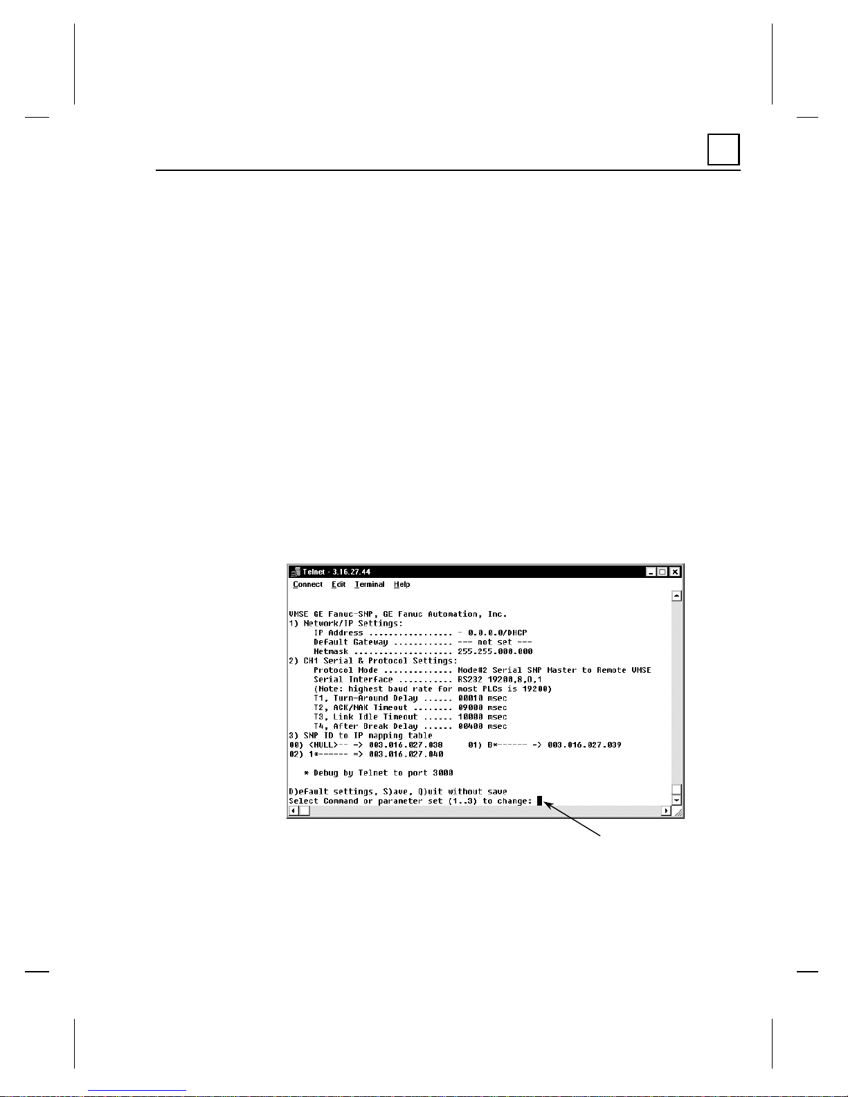
You have si x Command choices at the Con figurati on screen Command Pr ompt (see
next figure). You do not have to press the Enter key after typing a command number
or letter.
•
1 – to configure Network/IP Settings
•
2 – to con figure CH1 S e rial and Protoc ol Set tin gs
•
3 – to configure SN P ID to IP Mapp i ng Ta ble
•
d – to revert to default settings
•
s – to sa ve your changes and quit
•
q – to qu it without saving your cha nges
1
Figure 1-9. VMSE Configuration Screen
GFK-1852 Chapter 1 Introduction and Quick Start 1-9
Command Prompt
Page 17
1
P
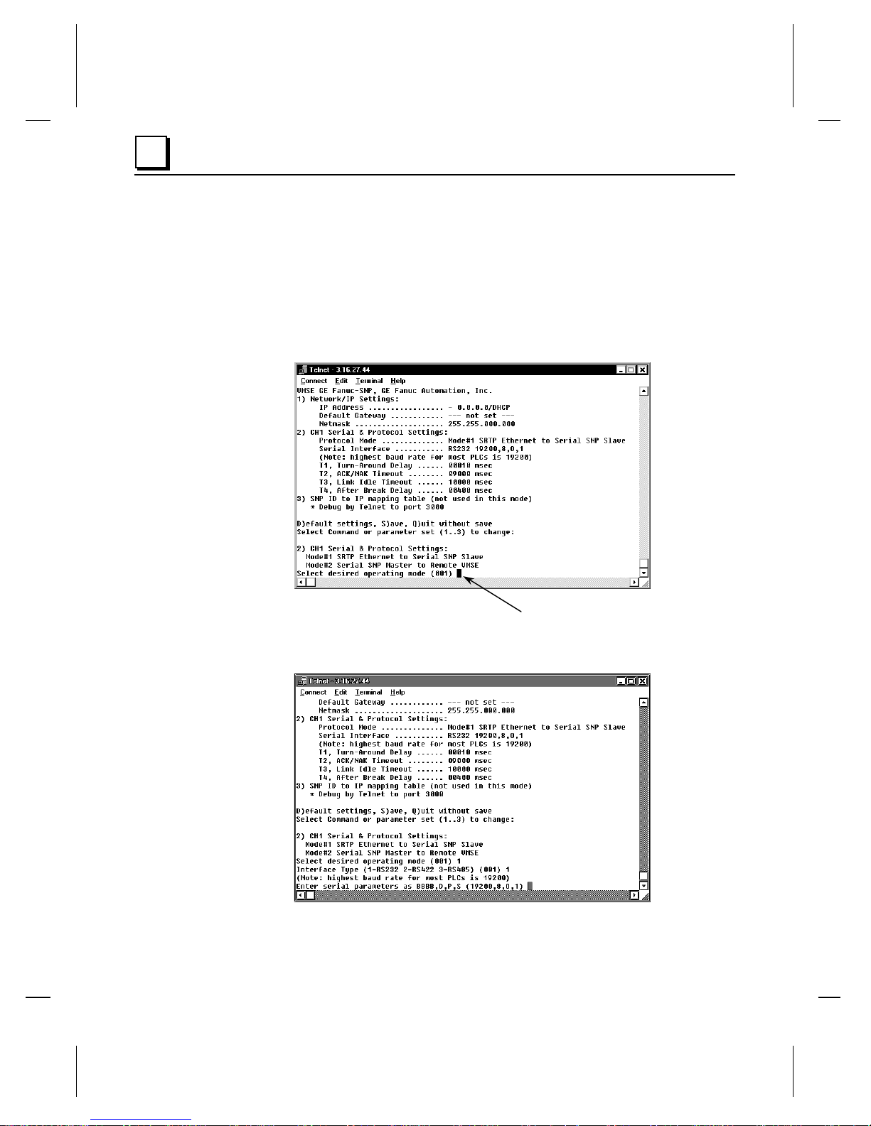
Configuration Example
The following figure shows the results of pressing the 2 key to select the “CH1 Serial
and Protocol Se ttings ” parameter group.
Notice that the first parameter in the group (“Pr otocol Mode”) is displayed. The
current value is shown in parentheses (001 in this example) before the prompt.
Simply pressing the Enter key would retain the current parameter value; typing 2 and
pressing the Enter key would set the Protocol Mode parameter to Mode #2.
Figure 1-10. Configuring the “Protocol Mode”
After each parameter value has been entered, the next parameter in order will appear
at the prompt , a s shown in th e fol lowi ng figure:
Figure 1-11. Continuing Configuration of the “CH1 Serial & Protocol Settings”
1-10 VersaMax Seri al to Ethernet Adapter User's Manual – July 2000 GFK-1852
arameter Prom p t
Page 18

Introduction and Quick Start
Once you finish configuring all of the param eters in th e s elected gr ou p (“CH1 Serial
& Pr otocol S e ttings ” in the above example), you will be returned to the Command
Promp t where you can continu e editin g p ar ameter s or you can exit.
Be sure to type S if you desire to save your changes when exiting.
1
Modbus is a trademark of Gould, Inc.
MS-DOS is a registered trademark of Microsoft, Inc.
CIMPLICITY, Logicmaster, Series 90-30, Series 90-70, Series Six
VersaMax, and VersaPro, are trademarks of GE Fanuc NA.
GFK-1852 Chapter 1 Introduction and Quick Start 1-11
,
Page 19

Chapter
2
VMSE Interfaces
Serial Interface
The VMSE has RJ45 and screw block serial ports. The RJ45 port only supports
RS232, whereas the screw block port supports RS232 and RS485/422. By setting the
switch located on the face of the VMSE and configuring the VMSE setup, RS232 or
RS485/422 can be selected.
NOTE: The V MSE is a s in gle seria l port devi ce, meaning that only one port can be
used at a time. In the configuration menu, Chan nel One r efers to eith er one of the
ports being used.
Figure 2-1. VMSE Ports and Features
GFK-1852 2-1
Page 20

2
Network Interface
The VMSE supports 10 Mbit Ethernet through its RJ45 (10BaseT) connector.
Hardware Addres s (MAC Addr e ss)
The first three bytes are fixed, and read 00-20-4A. The fourth, fifth, and sixth bytes
are un iq u e for each VM SE an d are used to generat e th e s er ial number . The addr es s is
in Hex notation.
Power Requirements
The VMSE is not shipped with a power supply. The required input voltage can vary
between 9VDC an d 3 0 V DC with a maximum of 3 Wat ts. The VMSE can be
powered from the 24 Volt supply on the VersaMax, Series 90-30, or an external
supply can be used. Take care not to exceed the ca pa city of th e V er s aMax or Series
90-30 power supply .
2-2 VersaMax Seri al to Ethernet Adapter User's Manual – July 2000 GFK-1852
Page 21

Chapter
3
Network Protocols
The VMSE produ c t use s T CP/IP protocol s for network commun icat ion . The
supported standards are: ARP, UDP, TCP, ICMP, Telnet, TFTP, DHCP, and SNMP.
For transparent conn ection s, TC P /I P ( binary str eam) or Telnet protocols are used.
Fir mwar e upgrades c a n be made wi th th e TFTP protocol.
The IP protocol defi nes addressi ng, routing and data block ha ndlin g over the
network. Th e T CP (tra nsmission contr ol pr otocol) ass ures t hat no dat a is lost or
dupl icated, and that everything sen t into the connecti on on one side arrives at the
target exactly as it was sent.
For typical datagram applications where devices interact with others without
maintainin g a p oint to poin t con necti on , a UDP datagram is us ed .
Packing Algorithm (PassThru Firmware only)
The two ava ilabl e pa ck et algorithms (wh ich define how and when pa ck ets are sent to
the network) are software select able. The standard algor ithm is optimized for
applications where VMSE is used in a local environment, allowing for very small
delays for sing le chara cters while trying to k eep the packet count low. The alternate
packing algorithm minimizes th e packet count on th e net wor k , and is es p ecially
useful for applications in routed Wide Area Networks. Various parameters can be set
in this mode to economize the serial data stream.
IP Address
Every active device connected t o the TCP/IP n etwork must h ave a unique IP address.
This IP address i s us ed to reference a specifi c d evi ce, for example, to build a
connection to the VMSE’s serial port. See Appendix A for a complete description of
IP Addressing.
GFK-1852 3-1
Page 22

3
Port Number
Every TCP connect ion and every UDP dat agram are d efined by a destinati on I P
addr ess and a port number. An IP address is n ecess ary to ad d r es s a device (h ost) on
the net wor k. A port nu mber is neces sary to ad dress an ap p lication or a ch an nel on a
networ k host. Th e port n umber can be comp ared to an ex tension on a PBX
(telep hone) system.
A Telnet application (login to a host with an ASCII terminal) is commonly assigned
TCP por t n um ber 23. Mor e th an one Teln et connection can be establi s hed to one host
using the Telnet port; however, the other peer IP address/port number combination
must be di ff eren t.
In th e VMSE (PassThru Firmwar e) , a port number can be confi g u red on th e ch an nel
(port). The VMSE uses this port number for outgoing messages and incoming
connections or UDP datagrams, which are addressed to its port number. Port 9999
(decimal) is used for remote configuration.
3-2 VersaMax Seri al to Ethernet Adapter User's Manual – July 2000 GFK-1852
Page 23

Chapter
4
Configuration
The VMSE can be confi g ured usin g remote or local methods. Either use an AS C II
terminal or a terminal emulation program to locally access the serial port, or use a
Telnet connection t o con figure th e un i t ov er the network.
The VMSE configuration is stored in nonvolatile memory and is retained without
power. The confi g urati on can be chang ed any time. Th e V MS E p er forms a res et after
the con fi g urati on ha s been chan g ed and stored .
Configuration Steps
The foll o wi ng steps n eed to be done, in th e or d er listed , to config ure the VMSE for
use. Thes e s teps can be d one via th e serial port or over the network u sing Telnet.
•
Set the Network Configuration
Mask.
- IP Address, Gateway Address, and Network
•
Load appropriate firmware if needed
TCP/RTU.
•
Configure Channel for applic a t i on
Chapter 1 for firmware option details.
- SRTP/SNP, PassThru, Modbus
- Depends on firm ware option chosen. See
Entering Serial Configuration Mode
An ASCI I ter minal or a P C with a terminal emul ation pr ogram can be connected to
the serial port on the VMSE. The terminal (or PC) should be configured for 9600
baud, n o parity, 8- bit, a nd 1 stop bi t.
To ent er configur ation m ode, the power on the VMSE mu s t be c ycl ed (powered off
and ba ck on ) . A ft er p ower-up, the self-test begi ns. About a s econd later, three
lowercase ‘x’ ch ar acter s mus t be sent to th e V M SE. These char acters mu s t all be
sent wi th in approx imately one s econd to start the configu r ation m od e.
GFK-1852 4-1
Page 24

4
NOTE:
at the terminal (emulation) and then power up the VMSE. This will ensure that the x
characters will arrive in time.
See Chapter 5 for more detail on using Serial communications to configure the
VMSE.
The easiest way to enter the configuration mode is to hold down the ‘x’ key
Entering Network Configur atio n Mod e_
To configure over the network, a Telnet connection to port 9999 must be established.
If you know the assigned IP address you can establish a Telnet connection to port 9999.
Under Windows 95/98/NT, open an MS-DOS command window and type the command
“telnet x.x.x.x 9999”, where x.x.x.x is an IP address already configured in the VMSE and
9999 is the desired TCP/IP port. Make sure you put a space between the x.x.x.x and
9999.
VMSE’s IP Add ress
Default IP Address
The VMSE is shipped with a default IP address of 0.0.0.0, which automatically enables
the DHCP within the VMSE.
If DHCP is enabled on the VMSE, and if there is a DHCP server to respond to VMSE’s
request when it’s booting up, the VMSE will then get an IP address, a gateway address,
and a subnet mask from the DHCP server. These addresses will not be shown in the
VMSE’s configuration screens (you will still see 0.0.0.0), however if you enter the
“monitor mode” (see Chapter 5) and from 0> prompt type NC (upper case) you will be
able to see the IP configuration of the VMSE.
NOTE:
address given to the VMSE by your DHCP serve r.
If DHCP is enabled on the VMSE, but there is no DHCP server on the network, the
VMSE's requ est wil l eventuall y t ime out and the unit will boot up with n o IP
address. As soon as a static IP address is assigned to the VMSE, the DHCP support
will be disabled within the product. To re-enable DHCP support, the IP address
should be s e t back to 0.0.0 . 0.
4-2 VersaMax Seri al to Ethernet Adapter User's Manual – July 2000 GFK-1852
Using th e ARP command (s ee below) you can always override the IP
Page 25

Configuration
Assigning a New IP Address
If the IP A ddre s s of t he VM SE is unknown or unde fine d, the following steps outline
how t o assign a t e mpor a ry IP address over the network.
1. Set a static A RP with the des ired IP a ddress using the har dware address of th e
VMSE, which is prin ted on the produ c t label. The foll owing ex ample shows the
use o f A RP in W i n95/98/NT (from the DOS prom pt) whe n th e ha rdware address
of the VMSE is 00-20-4A-01-64-0B.
In order for the A RP com mand to wor k in Windows, the ARP ta bl e on the
PC m ust ha ve at le ast one IP address define d oth er than its own. T ype
“ARP–A” at the DOS command prompt to verify that there is at least one
entry in the ARP table. If th er e is no other entry beside t he local machine,
ping anot her IP mach i ne on your network to bu ild the ARP ta ble. Th is ha s
to be a host ot her than the machine on which you are working. On ce there is
at lea st one entry in the ARP table, use the following commands to ARP an
IP address to the VMSE.
arp -s 191.12.3.77 00-20-4A-01-64-0B
2. Open a Telnet connection to port number 1. This connection will fail, but the
VMSE wil l ch ange it s IP ad dress to the one desi gnated in the ARP comman d
line.
4
telnet 191.12.3.77 1
3. Open a Telnet connection to port 9999, and set all required parameters.
telnet 191.12.3.77 9999
Confirm Telnet connection with <ENTER>.
NOTE:
VMSE. Be sure to log into VMSE and store the parameters to make the IP address
chang e p er manent .
The temp orary IP address by ARP is reverted aft er every power r eset of the
Unix
Unix arp details when the hardware address of the VMSE is 00-20-4A-01-64-0B.
The comm and example for most Unix systems is:
arp -s 191.12.3.77 00:20:4A:01:64:0B
GFK-1852 Chapter 4 Configuration 4-3
Page 26

4
Configuration Parameters
After configuration mode is entered (confirm with <ENTER>), the parameters can
be chan g ed ; default values can be confir med with the ENTER key. The para meters
must be saved , and the VMSE performs a power reset.
The Configuration for each of the firmware loads of the VMSE is slightly different.
If you n eed to load a different firmware than is in the VMSE, loa d the firmware first,
and th en fol low the directions for configur ation for the appropriate firmware. The
next sections contain the details for configuration setup for each of the firmware
loads.
4-4 VersaMax Serial to Ethernet Adapter User's Manual – July 2000 GFK-1852
Page 27

Configuration
SRTP/SNP Firmware – Configuration Setup
Figure 4.1 shows the Main Configuration screen for SRTP/SNP Firmware.
4
Figure 4-1. SRTP/SNP Firmware Configuration Screen
When finished wi th this screen, you ha ve th ree ch oi ces :
•
Press the “S” key to exit and save your chan g es .
•
Press the “Q” key to exit without saving your changes.
•
Press the “D” key to return to the default settings.
Network/IP Settings
To change the Network/IP settings, press ‘1’. The followi ng valu es can be
set/changed: IP Address, Gateway Address, NetMask.
GFK-1852 Chapter 4 Configuration 4-5
Page 28

4
IP Address
The IP address must be set to a unique value in your network. If you are not familiar
with IP addresses, pl ea se refer t o Appendix A.
If the VMSE is given an address that is already in use it will not connect to the
network.
Gateway IP Address
The router/g ateway addr es s is needed to commun icate to other LAN segments. The
default gateway must be set to the IP address of the router that connects these
segments. This address must be within the local network.
Netmask
A netmask defines how many bits from the IP address are to be taken as the network
section and how many bits are to be taken as the host section (re class A : 8/ 2 4
(net/host), class B: 16/16, class C: 24/8 bits). If set to 0, the standard netmask for the
actual IP addres s is used. A p p endix A cover s the calcu lation of the right value in
detail.
The VMSE prompt s for the number of host bits , an d then calculat es th e n etmask. It is
shown in standard forma t “255.255.xxx.xxx” when sa ve d parame ters are dis played.
Channel, Serial, and Protocol Setups
To chan g e the Chann el settings, pr es s ‘2’. The following values can be set/changed:
Protocol Mode, Seria l Interface setup, SNP T1-T4 timers.
: SNP T1 thru T4 timers should not be modified under normal circumstances. A
Note
thorough knowledge of S N P is re quired to modi fy the T1 – T4 timeout s.
SRTP/SNP Protocol Mode
The SRTP/SNP mode needs to be set based on how the VMSE will be used.
Mode#1
connected to a SNP slave. For this usage set the SRTP/SNP mode to MODE#1
(Enter a “1”). This is what is used for VersaPro or HMI to communicate with a PLC
by using a VMSE at the PLC.
4-6 VersaMax Serial to Ethernet Adapter User's Manual – July 2000 GFK-1852
- The most common usage (and the default) is for the VMSE to be
Page 29

Configuration
4
Mode#2
An examp le of this is:
A Seri es 90 P LC wi th a s er ial port set up for SNP where COMMREQs are used to
commun ication with oth er PLCs.
– Mode#2 is used to connect a SNP master to the network using a VMSE.
Serial Interface Configuration
Enter the interface setup as BBBB,D,P,S where BBBB is the baud rate ( default is
19200, D is the number of data bits (must be 8), P is parity (SNP defaults to O, the
letter “O” not zero, S number of stop bits ( must be 1).
The Default setting is the same as GE Fanuc PLC defaults; 19200 Baud, 8 data bits,
Odd pa ri ty, and 1 stop bit.
SNP T1 – T4 Timers
T1 – Turn-Around Delay
T2 – ACK/NAK Timeout
T3 – Link Idle Timeout
T4 – After Break Delay
SNP ID to IP Address Mapping ( only for SRTP/SNP Mode#2)
This setting is used only when VMSE configuration Mode#2 is used. This setting
directs messages to the VMSE which has the IP a d dress that cor responds to th e SN P
address i n thi s m apping ta ble. Up to four SN P IDs to IP addresses c an be entered.
Wildcards are to be used to allow multiple SNP IDs for communicate to PLCs
multidropped off of one VMSE. An example would be to enter:
SNP ID “A* ” IP Address 3.0.0.1
The SNP IDs “A1”, “AA”, and APPLE would all go the VMSE with the IP address
3.0.0.1 The PLCs with the corr ect SNP I D would respond to the SNP message
GFK-1852 Chapter 4 Configuration 4-7
Page 30

4
PassThru Firmware Configuration Setup
Figure 4.2 shows the Main Configuration screen for PassThru Firmware.
Figure 4-2. Pass Thru Firmware Configuration Screen
When finished wi th this screen, you ha ve th ree ch oi ces :
•
Press the “9” key to exit and save your changes.
•
Press the “8” key to exit without saving your changes.
•
Press the “7” key to activate the default settings.
Basic Parameters
To change the basic parameters (Server Configuration), press ‘0’. The following
values can be set/ changed : IP Addr es s, Gateway Address, N etMask, an d T elnet
Password.
4-8 VersaMax Serial to Ethernet Adapter User's Manual – July 2000 GFK-1852
Page 31

Configuration
IP Address
The IP address must be set to a unique value in your network. If you are not familiar
with IP addresses, pl ea se refer t o Appendix A.
If the VMSE is given an address that is already in use it will not connect to the
network.
Gateway IP Address
The router/g ateway addr es s is needed to commun icate to other LAN segments. The
default gateway must be set to the IP address of the router that connects these
segments. This address must be within the local network.
Netmask
A netmask defines how many bits from the IP address are to be taken as the network
section and how many bits are to be taken as the host section (re class A : 8/ 2 4
(net/host), class B: 16/16, class C: 24/8 bits). If set to 0, the standard netmask for the
actual IP addres s is used. A p p endix A cover s the calcu lation of the right value in
detail.
4
The VMSE prompt s for the number of host bits , an d then calculat es th e n etmask. It is
shown in standard forma t “255.255.xxx.xxx” when sa ve d parame ters are dis played.
Telnet Configuration Password
The telnet
setup menu via a Telnet connection to port 9999. To access the setup menu through
the serial port, it is not necessary to
the Channel Sp ecific Parameter s screen.
configuration password can be set to disable unauthorized access to the
enter the password.
Entering “2” moves you to
Channel 1 Parameters
To chan g e the Chann el 1 configur ation, press “1”. The following sections describe
the item that can be changed and the valu es to use.
Baud Rate
The baud rate can be set within the defined limits from 300 to 38400 bits per second.
GFK-1852 Chapter 4 Configuration 4-9
Page 32

4
Interface Mode
The line interface (I/F) mode is a bit-coded byte with the following meanings. It is
entered in he xadecima l no tation:
)XQFWLRQ
RS-232C 0 0
RS-422/485 0 1
RS-485 2-wire 1 1
7 Bit 1 0
8 Bit 1 1
No Parity 0 0
Even P a rity 1 1
Odd Parity 0 1
1 Stop bit 0 1
2 Stop bit 1 1
Figure 4-3. Interface Mode Operation
Common settings:
RS-232C, 8-bit, No Parity, 1 stop = 0x4C
RS-232C, 7-bit, Even Parity, 1 stop = 0x78
RS-485, 2-Wire, 8-bit, No Parity, 1 stop = 0x4F
RS-422, 8-bit, Odd Parity, 2 stop = 0xDD
The bit combination can be easily converted to hexadecimal notation for input. See
Appendix B for conversi on tables.
Flow Control
This parameter sets the local handshake method for stopping and starting output.
Generally, flow control is not required if the connection is used to pass a blocked
protocol with block siz es <1k ( ACK/NAK).
No flow control: 00
XON/XOFF flow control in both directions: 01
Hardware hand shake wi t h RT S/CTS l i nes: 02
XON/XOFF, pass characters to host: 05
4-10 VersaMax Seri al to Ethernet Adapter User's Manual – July 2000 GFK-1852
Page 33

Configuration
Port Number
This setting is the source port number in TCP connections, and is the number used to
identify the channel for remote initiating connections. The port number may not be
set to 0 or 9999 (range: 1-65535). In general the port numbers 0..1023 are reserved in
UNIX systems for s p ecific app lications. It is advisable t o u se number s in the rang e
2000-30000 to avoid potential conflicts.
If th e UDP Datagram mod e i s s el ected, the port num ber is used as th e UDP sou rce
por t num be r for outg oing datagram s ; datagrams sen t to the V M SE with this port
number are recei ved to this ch an nel.
Remote IP Address
When automatic connection mode is selected, a connection is made to this IP address
on the network .
Remote TCP Port
4
The remote TCP port number must be set to use automatic connections and can also
be configured for manual connect mode. This parameter defines the port number on
the target host to which a connection is attempted.
NOTE:
use the remote port number 23 (this is the Internet standard port number for Telnet
services).
This port number is also used as the UDP destination port number for transmitted
datagrams, provided the VMSE is used in UDP mode.
GFK-1852 Chapter 4 Configuration 4-11
To connect an ASCI I terminal to a h ost u s ing a VMSE for login purposes,
Page 34

4
Connect Mode
This parameter defines how the VMSE makes a connection and how it reacts to
incomi ng conn ection s over the net wor k.
Function 7 6 5 4 3 2 1 0
Connection Accept ance
-nev e r ac cept inc oming 0 0 0
-accept incom ing with active DTR only 0 1 0
-accept unconditional (if not busy) 1 1 0
Response on Seri al to Connect
-nothing (quiet) 0
-character response: (C=conn., D=disc.,
N=not availab le/unreachable )
Active Connection Startup
-no active connection startup 0 0 0 0
-start connection with any character on
the se ri al line
-start connection with acti ve-going
DTR line
-start connection with CR (0x0d) only 0 0 1 1
-manual connection startup
(‘C’ + address)
Datagram Mode
Modem Emulation Mode
1
000 1
001 0
010 0
110 0
011 0
Figure 4-4. Connect Mode Options
Please refer to Appendix B for information on converting values to hexadecimal
format.
Automatic Connection Address
Using either of the serial ports, an automatic TCP connection to a network node can
be configured by setting the remote IP address and the TCP port number parameters.
If automatic connection is selected, all parameters must be supplied in full.
If manual connection startup is configured (with “C” + address/port ), onl y t he part
not supplied in the command string is used. In manual mode, the last byte of the
address must be supplied.
4-12 VersaMax Seri al to Ethernet Adapter User's Manual – July 2000 GFK-1852
Page 35

Configuration
4
Example
TCP port number is 1234 :
C121.2.4.5/1<
complete override - connection is started with host 121.2.4.5, port 1.
C5<
This means connect to 129.1.2.5, port 1234.
C28.10/12< ENTER >
This means connect to 129.1.28.10, port 12.
: The configured remote I P address within the VMSE is 129.1.2.3 an d the
>
ENTER
ENTER
>
Datagram Mode
When selecting this option you will be prompted for Datagram type
Datagram type: 01 (Directed UDP)
Modem Emulation Mode
In modem emulation mode, the VMSE presents a modem interface to the attached
serial device by accepting AT-style modem commands and “wiggles” the modem
signals correctly. Nor mally th ere is a modem connected to a PC and a modem
connected to some other remote machine. A user must dial from his/her PC to the
remot e machin e an d accumulate phon e charges for each conn ection. Wi th the VMSE
in modem mode, you can replace your modem s wi th V MS E and use an Ethernet
conn ection instead of a ph one call al l without having t o ch an ge communications
appli cation s an d ma ke potent ially-expensive phone calls.
Modem mode is selected by setting the “connect mode” to 0x06 (no echo &
acknowledgments) or 0x16 (with echo & acknowledgments.) In modem mode the
following strings can be used:
ATDTx.x.x.x,pppp or ATDT x.x. x.x/pppp
This is used to make a connection to an IP address (x.x.x.x) and a remote port
number (pppp.)
ATDTx.x.x.x
Without a port number, this will make a connection to the remote port number
defin ed wi thin the VMSE.
ATD
If no remote IP address and port number are defined within the VMSE, this
command will force the VMSE into “monitor mode”.
GFK-1852 Chapter 4 Configurati on 4-13
Page 36

4
ATD0.0.0.0
If a remote IP address and port number are defined within the VMSE, this command
will force the VMSE into “monitor mode”.
ATDx.x.x.x
Without a port number, this will make a connection to the given IP address (x.x.x.x)
and the remote port number configured within the VMSE.
All other 'AT' commands with “connect mode” set to 0x16 will acknowledge with an
OK, but will not be acted upon.
If the VMS E is in modem emulation mode and the serial port is idle, the VMSE can
still accept networ k TCP connect ions to the serial ports if the “connect mode” is set
to 0xC6 (with no echo) or 0xD6 (with echo).
Disconnect Mode
In di scon nect mode, DTR drop can be a ctivat ed or ignored to end a connect ion:
- Di s c onne c t with DTR drop: 80
- Ignore DTR: 00
Force Telnet Mode
With an other bit in the disconnect m od e, the VMSE can be for ced into Telnet
(terminal) mode and the setup for the terminal name can be enabled:
- activate Telnet mode and terminal type setup: 40
4-14 VersaMax Seri al to Ethernet Adapter User's Manual – July 2000 GFK-1852
Page 37

Configuration
Buffer Flushing
With this parameter it is possible to control line handling and network buffers with
conn ection startup and disconn ect. Also, selection betwe en two different p acking
algorit h ms is possibl e.
Function 7 6 5 4 3 2 1 0
Clear input buffer (line to network)
- with active connection: 1
- with passive connection: 1
- at time of disconn ect: 1
Clear output buffer (network to line)
- with active connection: 1
- with passive connection: 1
- at time of disconnect: 1
Alternate packing algorithm 1
Figure 4-5. Buffer Flushing Options
Inactivity Timeout
With this parameter an inactivity time can be set. If the set time expires without an
activity on the serial line, the connection is dropped.
4
Pack Control
Alternative pack algorithm settings are controlled here. Set this value to 00 if
specific function s are not needed.
Function 7 6 5 4 3 2 1 0
Idle time to force tra ns mit: 12ms (avg .) 0 0
Idle time to force tra ns mit: 52ms (avg .) 0 1
Idle time to force transmit: 250ms (avg.) 1 0
Idle time to force transmit: 5 secs (!) 1 1
No tr aili ng chars after sendchar(s) 0 0
One trailing char after sendchar(s) 0 1
Two trailing chars after send char( s) 1 0
Sendchars define 2-Byte sequence 1
Send immediate after Sendchar 1
Figure 4-6. Pack Control Options
“Idle time to force transmit” defines the time period after which all accumulated
chara cters are sent, regardless of the recognition of send character s.
GFK-1852 Chapter 4 Configurati on 4-15
Page 38

4
In some applications, CRC, Checksum, or other trailers follow the
end- of-sequence char acter. In these cas es , this op ti on h elps to ada p t frame
transmissi on to the fram e boundary.
If bit 4 is set, VMSE interprets the Sendchars as a 2-byte sequence; if reset, they will
be interpreted independently.
If bit 5 is not set, any other characters already in the serial buffer will be included in
the transmiss ion after a “transmit” condition is found. If the bit is set, the VMSE will
immediately send after recognizing the transmit condition (sendchar or timeout).
NOTE:
acknowledgement has to be sent.
A trans mission might occur if statu s information has to be exchanged or an
Send Characters
Up to two ch aracters can be entered in h ex adecimal repres entati on in the parameter
“sendchar.” If a ch ar acter r eceived on the serial line mat ches one of th es e characters,
it is immediately sent together with any awaiting characters to the TCP connection.
This i s s p ecially useful to minimiz e the respon s e time for s p ecific protocol ch aracters
on th e serial lin e (i .e. ETX, EOT etc.). Setting the first Sendchar to “00” disables the
recognition of
the char acter s .
Alter n ativel y, the two character s can be interpreted as a s eq uence (s ee “Pack
Control” section).
Telnet Terminal Type
This parameter appears only if the terminal type option is enabled by setting
bit 6 in the disconnect mod e. If set, the terminal name can be u s ed f or the Telnet
terminal type. Only one name can be entered.
If the terminal type option is enabled, VMSE also reacts to the EOR (end of record)
and binary options, which can be used for applications like terminal emulation to
IBM hosts.
4-16 VersaMax Seri al to Ethernet Adapter User's Manual – July 2000 GFK-1852
Page 39

Modbus TCP/RTU Firmware Configuration Setup
The next figure shows the Main Configuration screen for Modbus Firmware:
Figure 4-7. Modbus Hardware Configuration Screen
When finished wi th this screen, you ha ve th ree ch oi ces :
Configuration
4
•
Press the “S” key to exit and save your chan g es .
•
Press the “Q” key to exit without saving your changes.
•
Press the “D” key to return to the default settings.
Network/IP Settings
To change the Network/IP settings, press ‘1’. The followi ng valu es can be
set/changed: IP Address, Gateway Address, NetMask
IP Address
The IP addres s must be s et to a uniq ue value in your network. If you are n ot familiar
with IP addresses, pl ea se refer t o Appendix A.
If the VMSE is given an address that is already in use it will not connect to the
network.
GFK-1852 Chapter 4 Configurati on 4-17
Page 40

4
Gateway IP Address
The router/g ateway addr es s is needed to commun icate to other LAN segments. The
default gateway must be set to the IP address of the router that connects these
segments. This address must be within the local network.
Netmask
A netmask defines how many bits from the IP address are to be taken as the network
section and how many bits are to be taken as the host section (re class A : 8/ 2 4
(net/host), class B: 16/16, class C: 24/8 bits). If set to 0, the standard netmask for the
actual IP addres s is used. A p p endix A cover s the calcu lation of the right value in
detail.
The VMSE prompt s for the number of host bits , an d then calculat es th e n etmask. It is
shown in standard forma t “255.255.xxx.xxx” when sa ve d parame ters are dis played.
Serial and Mode Settings
To chan g e the Chann el settings, pr es s ‘2’. The following values can be set/changed:
Protocol, S erial Int erface
Protocol
At the first prompt, select 1 for Save or 2 for Master . At th e s e c ond promp t, select 1
for Modbus/RTU or 2 for Modbus/ASCII.
Serial Interface
Enter the interface setup as BBBB,D,P,S,RSxxx where BBBB is the bau d rate
(default is 19200), D is the number of data bits , P is parity, S number of stop bits,
and RSxxx is 232 or 485 .
Modem Control Settings
To change the Modem settings, press ‘3’. The following value can be set/changed:
RTS Output
4-18 VersaMax Seri al to Ethernet Adapter User's Manual – July 2000 GFK-1852
Page 41

Configuration
Advanced Modbus Protocol Settings
To chan g e the Chann el settings, pr es s ‘4’. The following values can be set/changed:
Slave Addr/Unit ID , Modbus Serial Broadcasts, Character/Message Timeouts.
Modbus ID to IP Address Mapping ( only used for Master)
This setting is only available when Master is chosen. Entering “5” give s you the
Mapping screen.
4
GFK-1852 Chapter 4 Configurati on 4-19
Page 42

Chapter
5
Monitor Mode and F irmware Upgrad e
To enter monitor mode
Section 4.3). Instead of entering three “x ” keys, key in “xx1”. Within one second of
power-up, the VMSE will respond with a special prompt. To start the monitor mode
without network functions (no network connections), enter “xx2”. To enter the
monitor mode, in addition to “xx1” and “xx2”, you can also type “yyy” and log in.
To enter the monitor mode using a Telnet connection
established, you will see messages similar to the following examples:
Serial Number 1103062 MAC Address 00:20:4A:11:0B:F6
Software Version 00.9B1 (000630)
Press Enter to go into Setup Mode (wait to close)
At this point, type M (upper case). If you see the 0> prompt, it means that you have
entered the mon itor mode su ccessfully.
Monitor Commands
The foll o wi ng commands are ava ilable in the monitor mode. Many comman ds have
an IP address as an optional parameter (x.x.x.x). If it is given, the command is
applied to another VMSE with that IP address. If no IP address is given, the
command is executed locally.
: The same principal as setting the parameters is used (see
: After the Telnet session is
All com mands mus t be given in cap ital letters; on ly blank s (spaces) are accepted
between parameters.
Command Description
DL
x.x.x.x Send firmware to VMSE with IP x.x.x.x
SF
x.x.x.x Query software header reco rd (16-byte)
VS
GFK-1852 5-1
Download firmware to the V MSE
Page 43

5
Command Description
x.x.x.x Get configuration as HEX records
GC
x.x.x.x Set configuration from HEX records
SC
x.x.x.x Ch e ck with P i ng i f x.x.x.x i s alive and re achable
PI
AT
TT
NC
RS
x.x.x.x:n.n.n.n With this command, you can remotely assign an IP address to
SI
QU
Show the VMSE’s ARP table entr ies
Shows all the incoming and outgoing TCP connections (used
only with “monitor mo d e” fr om Telnet)
Shows t he IP configur ation of the VMSE
Resets the power on the VMSE
another VMSE, where x.x.x.x is th e n ew IP ad dress and
n.n.n.n is the remote VMSE serial number written twice. For
example:
SI194.39.78.234:146.138.146.138
IP address = 194.39.78.234
Remote VMSE serial # (146-138) = 146.138.146.138
NOTE:
this IP assignment cannot be done over the rout ers.
Quit - exit diagnostics mode
Sinc e t his i s obtained by sendi ng broadc ast packets,
Command result codes:
0
1
2
8
9
OK, no error
No answer from remote device
Cann ot r each remote d evi ce or does n ot answer
Wrong parame ter( s )
In valid c ommand
Firmware Downloa d Using Serial Port
Downloading is done in monitor mode. Once the VMSE is in monitor mode, by
using “DL” command, the VMSE will wait for the firmware image in Intel Hex
forma t. This mu st only be sent through th e s er ial interface. When the end r ecord is
5-2 VersaMax Seri al to Ethernet Adapter User's Manual – July 2000 GFK-1852
Page 44

Monitor Mode and Firmware Upgrade
received , the VM SE checks the integr ity of th e fir mware image and th en programs
the new firmwar e in the flash ROM. Do not switch off the power supply at this time.
A loss of po wer while r eprogra mming wil l r es u lt in a corrupt program image an d a
nonfunctional VMSE.
To load firmware with Hyperterminal, enter monitor mode by resetting the VMSE
and type xx1 after the * appears on the screen (you have about 1 second to type xx1).
The 0> pr ompt te lls you that you have e ntered Monit or mode
Type DL to enter download mode.
you will need to disconnect the Ethernet cable from the VMSE before you do
Note:
the download.
You must now use the H yperterm in al menu bar and select Trans fer… Send Text
File. This will give you a dialog box to select the file to download. Select the .hex
file for the firmware you want to load. The download will take about five minutes
and th e h yperterm in al will a ppear dead un til the d own load compl etes. The fi g ure
below shows the r es u lts after the download completes succes sfully.
After a comp lete reprogramming , the VMSE restarts.
After ch anging the firmware load in th e V M SE, select d efault s on the new firm ware
before setting the configuration to your desired settings; this keeps the VMSE from
becoming confused.
5
Figure 5-1. HyperTerminal Dialog Box
GFK-1852 Chapter 5 Monitor Mode and Firmware Upgrade 5-3
Page 45

5
Firmw are Distribution
To distribute th e firm ware of one VMSE to others, the “SF” command is used. After
entering monitor mode on the VMSE, simply send the firmware with the “SF”
comman d to the oth er d evi ces .
Firmware Download Using a Network Host
Windows NT Procedure
To downloa d new firmware from a com p u ter to a VMSE, it i s neces sary to h ave a
TFTP (Trivial File Transfer Protocol) client send a binary file. Windows NT has a
TFTP client built-in, but Windows 95/98 users must obtain TFTP software. See the
“Obtaining TFTP Software for Windows 95/98” section on the last page of this
chapter. The parameters to send a binary file are as follows:
•
Host – enter the IP addr es s of t he VMSE you are downl oa d ing.
•
Source ( or Local File) – a full path to the file to download to the VMSE.
•
Destination (or Remote File) – this a like a pass word in th e VM S E you a re
downloading.
•
PUT– send the file to the VMSE.
Go to the Command Prompt (MS-DOS Prompt), key in the above information, and
then press th e Ent er key. See the example in th e fi gure and followin g ex planat ion:
Figure 5-2. Using TFTP in Windows NT to store files to the VMSE
The fig ure above shows a successful st ore to th e VM SE at IP addres s 3.16.27. 40.
5-4 VersaMax Serial to Ethernet Adapter User's Manual – July 2000 GFK-1852
Page 46

Monitor Mode and Firmware Upgrade
345
6
Windows NT Command Line Example Code Explanation
C:\>tftp –i 3.16.27.40 PUT d:\snp42d.rom G1
5
1
2
1. C:\> is the comman d prom pt
2. tftp is the execute command for the TFTP software
3. -i tells TFTP to send a binary file
4. The host field is the IP addr ess of the target VMSE
5. PUT is the comman d that sends the fil e to the VMSE
6. The source file (including full path) to be sent to the VMSE
7. The destination field is like a password in the target VMSE
VMSE Firmware File List:
Functionality
SNP/SRTP SNP42.HEX SNP42.ROM G1
PassThru CoBox3-6.Hex CoBox3-6.ROM 3Q
Modbus Modbus.Hex Modbus.Rom 4D
File for Serial
Download
File for Network
Download
7
Destination
(password)
Destination (Password)
Destination (password ) for Network loads depend on what file is already in the
VMSE. Enter the Destination code based on what is already in the VMSE not on
what you are downloading.
For example, if you are downloading PassThru into a new unit which has the default
software of SNP/SRTP, you would enter a destination of G1.
destination is case sensitive. The letter “G” in this example must be upper case.
GFK-1852 Chapter 5 Monitor Mode and Firmware Upgrade 5-5
Note: The
Page 47

5
Windows 95/98 Procedur e
Download the TFTP software as described below, then follow the instructions in the
software’s built-in help file.
Obtaining TFTP Software for Windows 95/98
As of this writing, a freeware TFTP software program called PumpKIN is avai lable
for Windows 95/ 9 8 from the foll o wi ng Web site:
www.klever.net/kin/pumpkin.html
Once the page app ears, scr ol l down to th e d own load sel ection ta bl e and downl oa d
the “BANDWIDTH KILLER” version (either the .exe or .zip version).
PumpKIN software is copywrited 1997, 1998 by Klever Group, Inc.
Windows is a r eg istered trademark of Microsoft , Inc.
5-6 VersaMax Serial to Ethernet Adapter User's Manual – July 2000 GFK-1852
Page 48

Chapter
Serial Line Interfaces
6
Serial Line Interfaces
The VMSE has RJ45 and screw block serial ports. The RJ45 port only supports RS-232, whereas the screw block port supports RS-232 and RS-485/422. By setting the
switch located on the face of the VMSE and by selecting the matching setting with
the configuration software, RS-232 or RS-485/422 can be selected.
NOTE: The VMSE is a one serial port device, meaning that only one port can be
used at a time. In the configuration menu, channel one refers to either one of the
ports being used. If Channel two appears, it should be disregarded (this channel
applies to another type of product).
RJ45 Connector Pin-outs (RS-232)
The serial RJ45 connector supports up to 38400 bits per second and has the
following signals.
Pin Direction Function
1 Not Connected None
2 From VMSE RTS Ready to Send
3 To VMSE CTS Clear to Send
4 Signal Ground
5 From VMSE TXD Transmitted Data
6 To VMSE RXD Received Data
7 Hard-Wired Output DSR Data Set Ready
8 Not Connected None
Figure 6-1. Serial RJ-45 (RS-232) Pin-out Configuration
NOTE: Pin number 1 of the RJ-45 serial connector is the first pin from the top.
GFK-1852 6-1
Page 49

6
P
Screw Block Connector Pin-outs and Other Components
The next figure and following table illustrate and describe the screw block connector
pin-outs, LED operation, and other fe atures of the VMSE.
in 1
Figure 6-2. Front Panel Layout
6-2 VersaMax Seri al to Ethernet Adapter User's Manual – July 2000 GFK-1852
Page 50

Serial Line Interfaces
6
Item
Component
1 Screw terminal RXD or
2 Screw terminal CTS or
3 Screw terminal RTS or
4 Screw terminal TXD or
5 , 6, 7 Screw terminal NC No connection
8 Screw terminal GND Signal ground
9 Rese t sw itch RESET Push to pow er reset and initialize
10 LED (Red) Fault or
11 LED (Green) Ready SOLID: Connection to network host
12 LED (Yellow) Activity F LASHING: Network traffic
13 LED (Green) Link SOLID: VMSE has good Ethernet link
14 Connector (RJ45) Ethernet
15 Connector (RJ45) Serial port RJ45 connector for RS-232
16 LED (Yellow) Serial TXD F LASHING: Indicates transmission
17 LED (Y ellow) Serial RXD FLASHING: Indicat e s recepti on
18 Switch Switch for
19 Screw terminal DC + Operating power, positive
20 Screw terminal Ground Earth ground
21 Screw terminal DC - Operating power, negative
22 Screw terminal Ground Earth ground
Name Purpose
RS-232: RXD (Received Data)
RXA
RXB
TXB
TXA
Configurati
on
port
screw block
RS-422/485:RXA (Received Data -)
RS-232: CTS (Clear to Send)
RS-422/485: RXB (Received Data +)
RS-232: RTS (Req uest to Sen d)
RS-42 2/ 4 85 : TXB (T r ansmit Data +)
RS-232: TXD (Transmit Data)
RS-422/485: TXA (Transmit Data -)
SOLID: Fault in VMSE communication
(read error) or VMSE is in Configuration
Mode
established
RJ45 connector for Ethernet 10BaseT
from the serial port
to the serial port
UP: Serial RS-232
DOWN: Serial RS-422/ 485
Figure 6-3. Front Panel Components
NOTEs:
•
For RS-485 2-wire functionality, pins 1 & 4 and 2 & 3 of the screw terminals
must be con nected together.
•
The RJ-45 Ethernet connector uses industry standard 10Base T connections.
GFK-1852 Chapter 6 Serial Line Interfaces 6-3
Page 51

6
P
1
I
M
176
5
8
3
4
2
N
N
P
N
N
N
N
N
N
NCN
Cable Diagrams
Cable IC200CBL504
RS-232 Serial Communications for VMSE RJ45 Serial Port to VersaMax
Nano/Micro PLC RJ45 Port
This ca bl e is shipp ed in the box with th e V M SE an d can also be pu rchased
separately.
VMSE Connector
(RJ45)
Pin 1
C200CBL504
arkin g denotes PL C e nd
0cm (4 inches)
Figure 6-4. IC200CBL504 Cable
VMSE Conn e ct or
C
1
C
2
RXD - 6
TXD - 5
Sig. Gnd.- 4
3
C
7
8
C
Figure 6-5. Wiring Diagram for IC200CBL504
Nano/Micro PLC
Connec tor (RJ45)
To PLC
in 1
LC Connector
C
C
- TXD
- RXD
– Sig. Gnd .
C
C
C
6-4 VersaMax Serial to Ethernet Adapter User's Manual – July 2000 GFK-1852
Page 52

Serial Line Interfaces
187
6
5
3
2
4
N
N
D
N
N
NCN
N
N
NCN
9
N
User-Built Cable #1: VMSE RJ45 Serial to Miniconverter
This ca bl e is not currently sold by GE Fan uc. Details ar e provided so you can build
your own cable.
Application:
To connect a VMSE’s RJ-45 Serial port (RS-232) to the RS-232 port of an
IC690ACC901 Miniconverter (RS-232 to RS422/485).
6
VMSE Connector
Female Connector
(RJ45)
Pin 1
Figure 6-6. VMSE RJ45 Serial to RS232/485 Miniconverter
MSE RJ45 Connector
RXD - 6
TXD - 5
Sig. Gnd. 4
C
1
C
2
3
C
7
8
C
C
C
C
C
C
Figure 6-7. Wiring Diagram
Specifications
•
RJ45 Connector: Male, 8-pin
(9-Pin, D-Sub)
To Miniconverter
-Sub Connector
- SD
- RD
Sig. Gnd.
•
D-Sub Connector: Female, 9-pin
•
Cable: Standard RS-232 serial cable
•
Maximum cable length: 15 meters (50 feet)
GFK-1852 Chapter 6 Serial Line Interfaces 6-5
Page 53

6
1
6
8
7
5
2
3
4
N
D
N
N
N
9
N
User-Built Cable #2: VMSE RJ45 Serial to PC 9-Pin Sub-D
For Serial Monitor/Load of VMSE
This ca bl e is not currently sold by GE Fanuc. Detail s ar e provides so you can build
your own cable.
Application:
To connect a personal computer’s RS-232 serial port to a VMSE’s RJ-45 Serial port
for the purpose of (1) monitoring VMSE operation or (2) downloading firmware to
the VMSE.
VMSE Connector
(RJ45)
Pin 1
Figure 6-8. Cable for Serial Monitor/Load of VMSE
VMSE RJ45 Connector
C
1
DSR - 7
RXD - 6
TXD - 5
Sig. Gn d. - 4
CTS - 3
RTS - 2
8
C
Figure 6-9. Wiring Diagram
Specifications
Female Connector
(9-Pin, D-Sub)
To Personal
Computer
Serial Port
-Sub Connector
C
- DTR
- TD
- RD
– Sig. Gnd.
- RTS
- CTS
C
C
•
RJ45 Connector: Male, 8-pin
•
D-Sub Connector: Female, 9-pin
•
Cable: Standard RS-232 serial cable
•
Maximum cable length: 15 meters (50 feet)
6-6 VersaMax Serial to Ethernet Adapter User's Manual – July 2000 GFK-1852
Page 54

Serial Line Interfaces
168
7
5
2
3
4
N
N
V
D
N
NCN
N
NCN
9
N
User-Built Cable #3: VMSE RJ45 Serial to PC 9-pin D-Sub
This ca bl e is not currently sold by GE Fanuc. Detail s ar e provides so you can build
your own cable.
Application:
To connect the serial port (RS-232) of a personal computer (PC) running VersaPro
software to a VMSE’s RJ-45 Serial port (RS-232).
6
VMSE Connector
(RJ45)
in 1
Figure 6-10. VMSE to VersaMax Serial Cable
MSE RJ45 Connector
C
1
C
2
RXD - 6
TXD - 5
Sig. Gnd.- 4
3
C
7
8
C
Figure 6-11. Wiring Diagram
Female Connector
(9-Pin, D-Sub)
To Personal
Computer
Serial Port
-Sub Connector
C
- TD
- RD
– Sig. Gnd.
- RTS
- CTS
C
C
Specifications
•
RJ45 Connector: Male, 8-pin
•
D-Sub Connector: Female, 9-pin
•
Cable: Standard RS-232 serial cable
•
Maximum length: 15 meters (50 feet)
GFK-1852 Chapter 6 Serial Line Interfaces 6-7
Page 55

6
1
9
1
7
1
1
1
D
6
T
T
1
8
1
1
*
User-B uilt Cable #4: VMSE RS-422 Terminal s t o PLC
This ca bl e is not currently sold by GE Fanuc. Detail s ar e provides so you can build
your own cable.
Application:
Connects the VM S E t erminal block screw ter minal s t o a PLC 15-pin, D-s u b, RS422/RS-485 port such as is used on Series 90-30, Series 90-70, and VeraMax PLCs.
Note that the VMSE switch must be set in the RS-422 position and the firmware
configuration parameter “Interface Type” must be set to RS-422 (“Int erface T ype”
set to RS-485 wi l l not work).
To VMSE Screw
Terminals
(15-Pin, D- S u b)
To PLC
RS-422/485
Serial Port
Figure 6-12. VMSE Screw Terminals to 15-Pin D-Sub PLC Serial Port
Male Connector
VMSE
RX (A) -
RX (B) -
TX (B) TX (A) -
Signal Gnd. -
*
TP = Twisted Pair
**
If using a multidrop arrangement,
terminate only at the first and last
receive terminals.
00 ohm, 1/2 w resistor**
P*
P*
-Sub Connector
2 - SD (A)
3 - SD (B )
1 - RD (B’)
0 - RD (A’)
- Signal Gnd.
- Shield
- Term. Resis.
*
- RTS (A)
5 - CTS (A’)
- CTS (B’)
4 - RTS (B’)
Figure 6-13. Wiring Diagram
Specifications
•
D-Sub Connector: Male, 15-pin
•
Cable: Shielded, twisted-pair rated for RS-485 use. Ground shield at one end
only, as shown above.
•
Maximum cable length: 1200 meters (4,000 feet)
•
VMSE Switch setting: Set to RS-422 position (see Figures 6-2 and 6-3). Al so,
the “Interfa ce Type” configuration parameter must be set to RS-422.
6-8 VersaMax Serial to Ethernet Adapter User's Manual – July 2000 GFK-1852
Page 56

Serial Line Interfaces
M
S
S
E
Using the VMSE on an RS-422/485 Multidrop Network
The foll o wi ng fig ure shows an accep table configurati on for a multi drop network .
This example shows only two slave devices; if additional slaves were added,
termination would be required at the last slave device instead of at Slave #2.
6
lave #1 Slave #2
Serial
Line 2
Serial
aster
Switch=**
VMSE #1
Termination is required across RD or RX terminals at these locations if the serial line is
greater than 6 feet (2 meters) l ong
VMSE #1 must be se t to the c onf i gurat i on (RS-232 or RS-42 2) th at matches the Master
thernet Cable
witch=RS-422
VMSE #2
Figure 6-14. Using the VMSE in a Multidrop Arrangement
Multidrop Application Notes
•
Any se ria l line longe r th an 6 feet (2 mete rs) must hav e a term ination re s istor
across its receiv e terminals (RD or RX) at the end of each recei ve l ine.
•
The serial port on the VMSE #2 screw terminals mu s t be us ed s ince it i s th e on ly
VMSE port that supports RS-422. The VMSE’s RJ-45 Serial port cannot be
used since it is an RS-232 port only, and RS-232 does not support multidrop.
•
The switch on the front of the VMSE #2 must be set to RS-422 position to
enable RS-422 on the VMSE screw terminals. Also, the “Interfa ce Type”
configuration parameter must be set to RS-422 (no other setting is acceptable).
•
Serial Line 1 may be RS-232 or RS-422 as long as both Master and VMSE #1
are con fi g ured according ly.
•
For Serial Line 2, which must be an RS-422 line, match the specifications and
basic wiring scheme for User-Built Cable #4. All multidrop connections must
be made at the nodes inside th e connectors (thu s, each conn ector terminal would
have two wires attached), in a parallel “daisy-chain” style. No line stubs or
intermediate terminal blocks are permitted.
•
Each ser ial cable’s sh ield must be grounde d at on e end of the ca ble only.
•
The VMSE can be the on ly device connected to the mast er on Ser ial Line 1
shown in Figure 6-14 above.
GFK-1852 Chapter 6 Serial Line Interfaces 6-9
Page 57

6
P
P
E
Serial Port Connectors
IBM-AT Style Personal Computer Serial Port Connector
IBM-AT D-Sub,
Male, 9-Pin
in 1
xternal View
Pin No. Signal Desc ri ption
1 DCD Data Carrier Detect
2 RD Re ceive Data
3 TD Transmit Data
4 DTR Data Terminal Ready
5 GND Signa l Ground
6 NC No Connection
7 RTS Request to Send
8 CTS Clear to Send
9 NC No Connection
Figure 6-15. IBM-AT 9-Pin Serial Port Connector
in 6
6-10 VersaMax Seri al to Ethernet Adapter User's Manual – July 2000 GFK-1852
Page 58

Serial Line Interfaces
9-Pin, D-Sub PLC Seria l Port Connector
This connector is used for an RS-232 serial port on VersaMax CPUs. For additional
information on VersaMax serial ports, please refer to the
Manual
, GFK-1503.
56 3RUW
3LQ )HPDOH
'6XE
VersaMax PLC User’s
6
3LQ
3LQ
([WHUQDO 9LHZ
Pin-Out for 9-Pin D-Sub Seri al Con ne ctor (R S-4 32)
Pin Signal Direction Function
1 N/C No connection
2 TXD Output Transmit Data output
3 RX D In put R eceive Da ta input
4 N/C No connection
5 GND -- 0V/GND signal reference
6 N/C No connection
7 CTS Input Clear to Send input
8 RTS Outp ut Request t o S end outp ut
9 N/C No connection
Shell SHLD -- Cable Shield wire connection
3LQ
3LQ
Figure 6-16. 9-Pin D-Sub Serial Port Connector
GFK-1852 Chapter 6 Serial Line I nterfaces 6-11
Page 59

6
P
P
E
15-Pin, D-Sub PLC Serial Port Connector
This connector is used for an RS-485 serial port on all Series 90-30, Series 90-70,
and VersaMax CPUs, and on some Nano/Micro PLCs. For information on Series 90
ports, refer to the
Ve rsaMax serial ports, refer to t he
Series 90 PLC Serial Communications Manual,
VersaM ax PLC U ser’s Manual
VersaMax Nano/Micro ports, refer to the
User’s Manual
, GFK-1645.
RS-485 Port 15-Pin,
Female D-Sub
VersaM ax Micro PLCs and Nano PLCs
GFK-0582. Fo r
, GFK-1503. For
Pin 1
Pin 8
in 9
in 15
xternal View
Pin-Out for 15-Pin D-Sub Serial Connector (RS-422/485)
Pin Signal D irection Function
1 SHLD -- Cable Shield Drain wire connection
2, 3, 4 N/C No connec ti on
5 P5V Output +5.1VDC to power external d evices
6 RTS (A) O ut p ut Request t o S end (A) ou t p ut
7 GND -- 0V/GND reference signal
8 CTS (B’) Input Clear to Send (B) input
9 RT -- Resistor Termination (120 ohm) for RDA’
10 RD (A’) Input Receive Data (A) input
11 RD (B’) Input Receive Data (B) input
12 SD (A) Output Transmit Data (A) output
13 SD (B) Output Transmit Data (B) output
14 RT S (B) O utput R equ est t o S end (B) ou tput
15 CTS (A’) Input Clear to Send (A) input
Shell SHLD -- Cable Shield wire connection
Figure 6-17. 15-Pin D-Sub Serial Port Connector
6-12 VersaMax Seri al to Ethernet Adapter User's Manual – July 2000 GFK-1852
Page 60

Serial Line Interfaces
R
E
RJ-11 PLC Serial Port Connector
This connector is used for an RS-232 serial port on some Series 90-30 and Series 9070 CPUs. For additional information on these ports, please refer to the
PLC Serial Communications Manual,
S-232, 6-Pin RJ-11
Pin 1
GFK-0582.
xternal View
Series 90
6
Pin
Number
1 CTS Clear to Send
2 TXD Transmit Data
3 0V Signal Ground
4 0V Signal Ground
5 RXD Receive Data
6 RTS Request to Send
Figure 6-18. RJ-11 Serial Port Connector
Signal Name Description
GFK-1852 Chapter 6 Serial Line I nterfaces 6-13
Page 61

6
P
R
E
RJ-45 VersaMax Nano/Micro PLC Serial Port Connector
Port 1 on the VersaMax Nano and Micro PLCs is an RS-232 port with an 8-pin RJ45 vertical jack. In addition to being a general serial communications port, this port
is also us e d as the boot load e r port for upgradin g the P LC fir mwar e on th e s e P L Cs.
Note that the pin-out for th is connector is di fferent th an that of the RJ- 4 5 con nector
on the VMSE.
S-232, 8-Pin RJ-45
in 1
xternal View
Note: There is no shield or frame-ground or sh ield pin on this connector.
Pin Signal Direction Function
1 RTS Output Request to Send output
2 CTS Input Clear to Send input
3 RXD Input Receiv e Data i nput
4 TX D Output Transmit Data output
5 DCD Input Data Carrier Detect input
6 DTR Output Data Terminal Ready output
7 +5V Output +5VDC output to power external convert ers
8 GND -- 0V/Gnd signal reference
Figure 6-19. VersaMax Nano and Micro RJ-45 Serial Port Pin-Out
Note: The infor mation on th is page cam e from the
PLCs Use r ’s Manual
6-14 VersaMax Seri al to Ethernet Adapter User's Manual – July 2000 GFK-1852
, GFK-1645.
VersaMax Micro PLCs and Nano
Page 62

Serial Line Interfaces
IC690A CC 90 1 Mi niconver t er 9- Pi n, Male D-Sub Connecto r
The RS-232 end of the IC690ACC901 Miniconverter has a 9-pin, male D-sub
conn ector. Refer to the
0356, for a data sheet on the IC690ACC901 Miniconverter.
Series 90-30 PLC Hardware and Installation Manual
56 3RUW
3LQ 0DOH
'6XE
6
, GFK-
3LQ
3LQ
([WHUQDO 9LHZ
Pin-Out for 9-Pin D-Sub Male Miniconverter Serial Connector (RS-432)
Pin Signal Direction Function
2 SD Output Send Data
3 RD Input Receive D ata
5 GND -- 0V/GND signal reference
7 CTS Input Clear to Send
8 RTS Outp ut Request t o S end
3LQ
3LQ
Figure 6-20. IC690ACC901 Miniconverter RS-232 Connector Pin-Out
GFK-1852 Chapter 6 Serial Line I nterfaces 6-15
Page 63

Chapter
7
Technical Data
CPU, Memory, and Controllers
•
V.40 CPU, 10MHz clock
•
National Semiconductor DP839xx Ethernet Controller
•
128 kByte RAM, 128 kByte Flash EPROM
•
256 Byte E²PROM for parameter storage
Serial Interface
•
RJ-45 conn ector for RS232 interface
•
Screw terminals for RS232 or RS422/485 interface
•
Speed software selectable 300 to 38.4k baud
•
Switch selectable RS-232C or RS-422/485 – screw terminal connector only
Network Interface
•
Integrated 10BaseT port (RJ-45 connector)
Power Supply (not included)
•
Screw terminals for 9-30 Volt DC input from external supply
Power Consumption
•
Maxim u m 3 Watt
Operating Temperature
•
0-60 degrees C (32-140 degrees F)
GFK-1852 7-1
Page 64

7
6
(
D
LEDs
•
Four LEDs for Ethernet channel, link, activities, and error.
•
Two LEDs for serial channel status.
Case
•
Plastic case for DIN rail mounting
Dimensions
90mm
(3.54”)
0mm
2.36”)
epth = 36mm (1.42”)
Weight
•
Approx. 150g (0.33 lb)
7-2 VersaMax Seri al to Ethernet Adapter User's Manual – July 2000 GFK-1852
Page 65

Appendix
A
IP Addresses
IP Addressing
An IP address is a 32-bit value, divided into four octets of eight bits each. The
standard representation is four decimal numbers (in the range of 0..255), divided by
dots.
Example: 192.2.1.123
This is called decimal-dot notation.
The IP address is divided in two parts: network and host. To support different needs,
three ”network classes” have been defined. Depending on the network class, the la s t
one, two or thr ee byte s define the host , while th e rem aining part defines the network.
In th e follo wi ng, ‘x ’ stands for th e host part of the IP addr es s:
Class A Network
IP address 1.x.x.x to 127.x.x.x
Only 127 different networks of this class exist. These have a very large number of
potential connected devices (up to 16,777,216)
Example: 10.0.0.1, (network 10, host 0.0.1)
Class B Network
IP address 128.0.x.x to 191.255.xxx.xxx
These network s are used for large comp any networ k s . Every net wor k can consist of
up to 65,534 devices.
Example: 172.1.3.2 (network 172.1, host 3.2)
GFK-1852 A-1
Page 66

A
Class C Network
IP address 192.0.0.xxx to 223.255.255.xxx
These network ad dresses are most com mon and ar e often used in s mall companies.
These networks can consist of a maximum number of 254 hosts.
Example: 192.7.1.9 (network 192.7.1, host 9)
The remaining addresses 224.x.x.x - 239.x.x.x are defined as ”class D” and are used
as a multicast addresses.
The addresses 240.x.x.x. - 254.x.x.x are defined as "class E" and are reserved
addresses.
Network Address
The host address with all host bits set to "0" is used to address the network as a
whole (in routing entries, for example).
Broadcast Addres s
The address with the host part bits set to ‘1” is the broadcast address, meaning “for
every station”.
Network and Broadcast addresses must not be used as a host address (e.g.
192.168.0.0 identifies the entire network, 192.168.0.255 identifies the broadcast
address).
IP Netmask
The netm ask is used to divid e th e IP addres s di ff erent l y from the standard defi ned by
the classes A, B, C. A netmask defines how man y bits from th e IP address are to be
taken as the network section and how many bits are to be taken as the host section.
When the number of host bits is entered, the VMSE calculates the netmask. The
netmask is displayed in standard decimal-dot notation.
Network Bits Host Bits Netmask
Class A 8 24 255.0.0.0
Class B 16 16 255.255.0.0
Class C 24 8 255.255.255.0
Figure A-1. Standard IP Network Netmask
A-2 VersaMax Seri al to Ethernet Adapter User's Manual – July 2000 GFK-1852
Page 67

IP Addresses
Netmask Examples
Netmask Host bits
255.255.255.252 2
255.255.255.248 3
255.255.255.240 4
255.255.255.224 5
255.255.255.192 6
255.255.255.128 7
255.255.255.0 8
255.255.254.0 9
255.255.252.0 10
255.255.248.0 11
. .
. .
255.128.0.0 23
255.0.0.0 24
Figure A-2. Netmask Examples
A
Private IP Networks and the Internet
If your network is not connected to the Internet and there are no plans to make such a
connection you may use any IP address you wish.
If you are not connected to the Internet and have plans to connect, or you
are connected to the Internet and want to operate your VMSEs on an
Intranet you should use one of the sub-networks below. These network
numbers have been reserved for such networks. If you have any questions
about IP assignment consult your Network Administrator.
Class A 10.x.x.x
Class B 172.16.x.x
Class C 192.168.0.x
GFK-1852 Appendix A IP Addresses A-3
Page 68

A
Network RFC’s
For more information regarding IP addressing see the following documents. These
can be loca ted on th e World Wid e Web u sing one of th e direct or ies or indi ces :
RFC 950 Internet Stan dard Subn etting Proced u re
RFC 1700 Assigned Numbers
RFC 1117 Internet Numbers
RFC 1597 Address Allocation for Private Intern ets
A-4 VersaMax Serial to Ethernet Adapt er U ser's Manual – July 2000 GFK-1852
Page 69

Appendix
B
Binary to Hexadecimal Conversion Table
Hexadecimal digits have values from 0..15, represented as 0...9, A (for 10), B (for
11) ... F (for 15). Use the following table to convert binary-to-decimal-to-hex:
Decimal Binary Hexadecimal
0 0000 0
1 0001 1
2 0010 2
3 0011 3
4 0100 4
5 0101 5
6 0110 6
7 0111 7
8 1000 8
9 1001 9
10 1010 A
11 1011 B
12 1100 C
13 1101 D
14 1110 E
15 1111 F
Figure B-1. Decimal, Binary, and Hexadecimal Conversion Table
To convert a binary value that has more than four bits, separate it into groups of four
bits. (If the number of binary bits is not an even multiple of four, add leading zeroes
to make it an even multiple.) Each group of four binary bits represents a single
hexadecimal number. For example, let’s convert the binary number 1011110000 to
the hexadecimal number 2F0. First separate the binary number into groups of four
bits (add two leading zeroes): 0010 1111 0000. Then use the above conversion
table to find the hexadecimal value for each group: 0010 = 2, 1111 = F, 0000 = 0.
GFK-1852 B-1
Page 70

Appendix
C
The following product:
Declaration of Conformity
Declar at i on o f Con f ormity
according to ISO/IEC Guide 22 and BS 7514
Product N a me :
Product Number(s):
Conforms to the following standards or other normat ive documents:
Electromagnetic E missi ons:
Electromagnetic Immunity:
Product Safety:
Supplementary Information:
This product has been verified as being compliant within the class A limits of the FCC Radio
Frequency Devices Rules (FCC Part 15, Subpart B), revised as of October 1993.
"The product complies with the requirements of the Low Voltage Directive 73/23/EEC and
the EMC Directive 89/336/E
VMSE
IC200SET001
C1SPR22: 1993 Class “A”
EN55022, 1995 Class "A"
EN50082-1, 1992
EN60950, 1988 +A1, A2, A3, A4
GFK-1852 C-1
Page 71

Index
DTR disconnect, 4-14
A
ARP, 4-3
command example, 1-4
Automatic connection address,
4-12
B
Baud rate configuration, 4-9
Broadcast addres s , A-2
Buffer flushing, 4-15
C
Cable diagrams, 6-4
Cl ass A networ k, A-1
Class B network, A-1
Class C network, A-2
Configuration
memory, 4-1
parameters, 4-4
Telnet, 4-9
Configuration setup
SRTP/SNP, 4-5
Connect mode, 4-12
Connections
terminal screw, 6-3
Connect or, VMSE
pin-out, 6-1
Controller
specifications, 7-1
CPU
specifications, 7-1
Ethernet, 2-2
External transceiver, 2-2
Firmware
Flow control config., 4-10
Force Telnet mode, 4-14
Front panel layout
Gateway IP ad dress , 4-9 , 4-18
IC200CBL504
IC690ACC901 Miniconverter
Inactivity timeout, 4-15
Interface Mode config. , 4-10
IP address, 3-2, 4-6, 4-9, 4-17,
D
Datag ra m mode, 4-13
DHCP, 4-2
Diagrams
cable, 6-4
front panel layout, 6-2
Dimensions, 7-2
Disconnect mode
GFK-1852 Index-1
IP addressin g, A-1
IP Networks
Layout
E
F
download from VMSE to
VMSE, 5-4
download via network host, 5-4
downloading via serial port, 5-2
VMSE options, 1-2
of VMSE, 6-3
G
I
serial ca ble, 6-4
9-pin pin-out, 6-15
cable, 6-5
A-2, A-3
factory default, 4-2
forcing new IP, 4-2
remote, 4-11
private, A-3
L
VMSE front pane l , 6-3
Page 72

Index
LED
operation, 6-3
M
MAC address, 2-2
Memory
specifications, 7-1
Miniconverter
9-pin pin-out, 6-15
user-built cable, 6-5
Modbus ID to IP
address mapping, 4-19
Modbus protoc ol
advanced settings, 4-19
Modbus TCP/RTU
configuratio n, 4- 17
firmwa re , 1 -2
Modem emulation mode, 4-13
Monitor
VMSE cable, 6-6
Monitor mode
results codes, 5-2
Monitor mode commands, 5-1
Mul tidr op, u sing VM S E, 6-9
port number, 4-11
remote TCP port, 4-11
send characters, 4-16
PassThru
config. setup, 4-8
firmwa re , 1 -2
Personal comp u ter
serial port pin-out, 6-10
Pin-out
15-pin serial port, 6-12
9-pin serial port, 6-11
Miniconverter 9-pin, 6-15
personal computer, 6-10
RJ-11 serial port, 6-13
screw block connector, 6-2
VersaMax RJ-45 port, 6-14
VMSE Serial port, 6-1
PLC
15-pin serial port, 6-12
RJ-11 serial port, 6-13
Port number, 3-2, 4-11
Power
consumption, 7-1
input voltage, 7-1
requirement, 2-2
Private IP networks, A-3
N
Netmask, 4-6, 4-9, 4-18, A-2
Network host address, A-2
Network RFCs, A-4
Network/IP settings, 4-17
Remote configuration, 3-2
Remote IP address, 4-11
Remote TCP port, 4-11
RJ-11 conn ector pin-out, 6-13
RS-232
P
Pack con trol, 4 - 1 5
Packing alogrithm, 3-1
Parameters
basic, 4-8
basics, 4-5
configuratio n, 4- 4
DTR disconnect, 4-14
flow control, 4-10
gateway IP address, 4-9, 4-18
IP address, 4-6, 4-9, 4-17
netmask, 4-6, 4-9, 4-18
Index-2 VersaMax Serial to Ethernet Adapter U s er 's Manual–July 2000 GFK-1852
RS-422
RS-485
Scr e w block connect or
Send characters
R
selecting, 2-1
VMSE RJ45 connector, 6-1
cable, 6-8
multidrop, 6-9
selecting, 2-1
S
pin-outs, 6-2
Page 73

Index
para mete r se tting, 4-1 6
Serial and Mode settings, 4-18
Serial interface, 4-18
specifications, 7-1
Seri al line interfaces, 6-1
Se ri al port
15-pin pinout, 6-12
PC pin-out, 6-10
RJ-11 pin-out, 6-13
VersaMax 9-pin pino ut , 6- 11
SNP ID to IP
address mapping, 4-7
SRTP/SNP
firmwa re , 1 -2
Mode#2, 4-7
protocol mode, 4-6
T
TCP
auto connection, 4-12
connections, 4-11
TCP/IP, 3-1, 4-2
Telnet, 3-1, 3-2, 4-1, 4-3
configuratio n, 4- 9
force mode, 4-14
standard port no., 4-11
terminal type, 4-16
Temperature
operating rang e, 7-1
Timeout, inactivity, 4-15
U
UDP, 3-1
datagram mode, 4-11
destination port no., 4-11
Unix com mand examp le, 4-3
V
VersaMax
serial port pin-out, 6-11
VersaMax Nano/Micro
cable, 6-4
RJ-45 serial port, 6-14
VersaPro
interfa ce cable, 6-7
W
Weight
of VMSE, 7-2
Windows 95/98
command example, 4-3
GFK-1852 Index Index-3
 Loading...