

Page 1
Important Product Information VersaMax*
IP ADDRESS
RS485
PORT 2
RS232
PORT 1
CPUE05
FAULT
RUN
PWR
OK
IC200CPUE05
PORT 2
FORCE
PORT 1
PORT 1
LAN
STAT
ETHERNET
10 MBPS BASE T
ETHERNET
RESTART
MAC XXXXXXXXXXXX
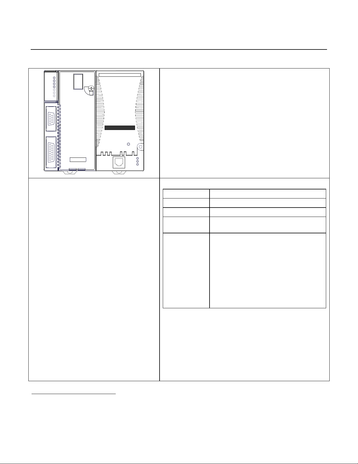
IC200CPUE05 shares the basic features of the other VersaMax*
PLC CPUs. It provides powerful PLC functionality in a small,
versatile system. CPUE05 can serve as the system controller for up
to 64 modules with up to 2048 I/O points. Two serial ports provide
RS-232 and RS-485 interfaces for serial communications. CPUE05
also provides a built-in Ethernet Interface. The RS-232 serial port
can be configured for Local Station manager operation to provide
access to diagnostic information about the Ethernet interface.
CPUE05 has 128KB of configurable memory.
In addition, CPUE05 is compatible with the EZ Program Store
device, which can be used to write, read, update, and verify
programs, configuration, and reference table data without a
programmer or programming software.
Features
▪ Supports up to 64 modules with up to 2048 I/O
points
▪ Can be either auto-configured or configured
from a programmer using configuration software
▪ 128KB of configurable memory for the
application program, hardware configuration,
registers (%R), analog inputs (%AI), and analog
outputs (%AQ)
▪ Programming in Ladder Diagram and
Instruction List
▪ Non-volatile flash memory for program storage
▪ Battery backup for program, data, and time of
day clock
▪ Super capacitor provides power to memory for
1 hour
- Over 1 hour, backup battery protects memory
contents up to 6 months.
- Backup battery has shelf life of 5 years when
not in use.
▪ Run/Stop switch
▪ Floating point (real) data functions
▪ Embedded RS-232, RS-485, and Ethernet
communications
▪ 70mm height when mounted on DIN rail with
power supply (sold separately)
Product Information
Revision
IC200CPUE05-LT
Power Supply
Requires PWRx02
Firmware
Version 3.10
Programmer
Compatibility
VersaPro software version 2.0 or later and
Machine Edition Logic Developer.
Expansion I/O
Compatibility
All types of I/O and communications modules can
be used in expansion racks. Some analog
modules require specific module revisions in
expansion racks, as listed below:
Module Module Revision
ALG320 B or later
ALG321 B or later
ALG322 B or later
ALG430 C or later
ALG431 C or later
ALG432 B or later
IC200CPUE05
GFK-1892TW CPU with Embedded Ethernet Interface
December 2016
*
Indicates a trademark of General Electric Company and/or its subsidiaries. All other trademarks are the property of their respective
owners.
© 2001-2016 General Electric Company. All Rights Reserved.
Page 2

2 CPU with Embedded Ethernet Interface
Size
Width: 4.95” (126mm) - along DIN rail
Length: 5.04” (128mm)
Depth: 2.72” (69.1mm)
Program storage
System flash, battery-backed RAM
Power Supply current consumption with no serial port
converter or EZ Program Store device
5Vdc uses 220mA
3.3Vdc uses: 570mA
Power Supply current consumption with serial port
converter or EZ Program Store device
5Vdc uses: 320mA
Floating point
Yes
Boolean execution speed
0.8 ms/K (typical)
Real time clock accuracy (for timer functions)
100ppm (0.01%) or ±9sec/day
Time of day clock accuracy
23ppm (0.0023%) or ±2sec/day @ 30°C.
100ppm (0.01%) or ±9sec/day @ full temperature range
Embedded communications
RS-232, RS-485, Ethernet
Configurable memory
128K bytes maximum
Ethernet Interface Specifications
Ethernet data rate
10Mbps (half- or full-duplex)
Ethernet port
RJ-45, UTP
Number of SRTP server connections
8
Number of Ethernet Global Data (EGD) configuration-based
exchanges
32
EGD Exchange limits
100 data ranges per exchange
1400 bytes of data per exchange
EGD Time Synchronization
Not Supported
EGD Selective Consumption
Yes
Load EGD configuration from PLC to programmer
Yes
Remote Station Manager over UDP
Yes
Local Station Manager
(RS-232)
Via CPU Port 1
GFK-1892TW IC200CPUE05
Specifications: IC200CPUE05
Page 3

CPU with Embedded Ethernet Interface 3
IC200CPUE05 GFK-1892TW
EMC Installation Requirements
To meet EN 55011 and FCC Class A radiated emissions, the Control system in which the IC695PNC001 module is used
shall be mounted in a metal enclosure when three or more IC695PNC001 modules are used. All surfaces of the
enclosure must be adequately grounded to adjacent surfaces to provide electrical conductivity. Wiring external to the
enclosure must be routed in metal conduit or the equivalent. The conduit must be mounted to the enclosure using
standard procedures and hardware to ensure electrical conductivity between the enclosure and conduit.
When installing, operating, or maintaining the IC695PNC001, personnel must insure any electrostatic charge is
discharged through the use of a grounded ESD strap or other means.
Installation Location
This product is intended for use with the VersaMax system. Its components are considered open equipment (having live
electrical parts that may be accessible to users) and must be installed in an ultimate enclosure that is manufactured to
provide safety. At a minimum, the enclosure shall provide a degree of protection against solid objects as small as 12mm
(fingers, for example). This equates to a NEMA/UL Type 1 enclosure or an IEC60529 IP20 rating providing at least a
pollution degree 2 environment. For details about installing VersaMax rack systems, refer to VersaMax Modules, Power
Supplies and Carriers User's Manual, GFK-1504.
Installation in Hazardous Areas
The following information is for products bearing the UL marking for Hazardous Areas or ATEX marking for explosive
atmospheres:
CLASS 1 DIVISION 2 GROUPS ABCD
This equipment is an open-type device and is meant to be installed in an enclosure suitable for the
environment that is only accessible with the use of a tool.
Suitable for use in Class I, Division 2, Groups A, B, C and D Hazardous Locations, or nonhazardous locations
only.
Warning – EXPLOSION HAZARD - SUBSTITUTION OF COMPONENTS MAY IMPAIR SUITABILITY FOR CLASS I,
DIVISION 2.
Warning – EXPLOSION HAZARD – DO NOT CONNECT OR DISCONNECT EQUIPMENT UNLESS POWER HAS BEEN
SWITCHED OFF OR THE AREA IS KNOWN TO BE NON-HAZARDOUS.
ATEX Zone 2
This module must be mounted in an enclosure certified in accordance with EN60079-15 for use in Zone 2, Group IIC and
rated IP54. The enclosure shall only be able to be opened with the use of a tool.
Page 4

4 CPU with Embedded Ethernet Interface
GFK-1892TW IC200CPUE05
Quick Start
Installation and initial startup procedures for the CPUE05 include the following steps. Before installing and operating the
CPUE05, refer to VersaMax PLC User's Manual, GFK-1503 for detailed information.
Pre-Installation check
Carefully inspect all shipping containers for damage. If any equipment is damaged, notify the delivery service
immediately. Save the damaged shipping container for inspection by the delivery service. After unpacking the
equipment, record all serial numbers. Save the shipping containers and packing material in case it is necessary to
transport or ship any part of the system.
Module Installation
This equipment may be mounted on a horizontal or vertical DIN rail. If mounted on a vertical DIN rail, the CPU module
must be located at the bottom. The CPU and connecting carriers must be installed on the same section of 35mm (1.38in)
x 7.5mm (.3in) DIN rail, 1mm (.04in) thick. Steel DIN rail is recommended. The DIN rail must be electrically grounded to
provide EMC protection. The rail must have a conductive (unpainted) corrosion-resistant finish. DIN rails compliant with
DIN EN50022 are preferred. For vibration resistance, the DIN rail should be installed on a panel using screws spaced
approximately 15.24cm (6in) apart.
Rated thermal specifications for the CPU module are based on a clearance of 50.8mm (2in) above and below the
equipment and 25.4 mm (1 inch) to the left of the CPU module.
1. Allow sufficient finger clearance for opening CPU door.
2. Allow adequate clearance for serial port and Ethernet cables.
3. Allow adequate space for power wiring.
The CPU with power supply attached fits into a 70mm (2.76in) deep enclosure.
Installing the CPU on the DIN Rail
The CPU snaps easily onto the DIN rail. No tools are required for mounting or grounding to the DIN rail.
Before joining module carriers to the CPU, remove the connector cover on the right-hand side of the CPU. Do not
discard this cover: you will need to install it on the last carrier, to protect the connector pins from contamination and
damage during use.
Page 5

CPU with Embedded Ethernet Interface 5
SEE NOTE 2.
M3.5 (#6) SCREW
15.9mm
0.62in REF
SPLIT LOCK
WASHER
FLAT WASHER
CPU
TAPPED
HOLE IN
PANEL
5.1mm
0.200in
4.3mm
0.170in
4.3mm
0.170in
Caution
Battery may explode if mistreated.
Do not recharge, disassemble, heat above 100°C (212°F), or incinerate.
IC200CPUE05 GFK-1892TW
Panel-Mounting
If excessive vibration is a factor, the CPU should also be screwed down to the mounting panel.
Note 1. Tolerances are ±0.13mm (0.005in) non-cumulative.
Note 2. 1.1-1.4Nm (10-12 in/lbs) of torque should be applied to M3.5 (#6-32) steel screw threaded into material
containing internal threads and having a minimum thickness of 2.4mm (0.093in).
Removing the CPU from the DIN Rail
1. Turn off power to the power supply.
2. (If the CPU is attached to the panel with a screw) remove the power supply module. Remove the panel-mount
screw.
3. Slide the CPU away from the other modules until the connector on the right side disengages from the next carrier.
4. With a small flathead screwdriver, pull the DIN rail latch outward while tilting the other end of the module down to
disengage it from the DIN rail.
Activating or Replacing the Backup Battery
The CPU is shipped with a battery already installed. The battery holder is located in the top side of the CPU module.
Before the first use, activate the battery by pulling and removing the insulator tab.
To replace the battery, use a small screwdriver to gently pry open the battery holder. Replace battery only withACC001
from your PLC supplier, or with Panasonic battery: BR2032. Use of another battery may present a risk of fire or
explosion.
Page 6

6 CPU with Embedded Ethernet Interface
RUN/ON
STOP/OFF
PORT 1
LAN
STAT
ETHERNET
10 MBPS BASE T
ETHERNET
RESTART
Ethernet Restart
Pushbutton
GFK-1892TW IC200CPUE05
Switching the PLC Operating Mode
The CPU Run/Stop mode switch is located behind the module door. This switch can be used to place the CPU in Stop or
Run mode. It can also be used to block accidental writing to CPU memory and forcing or overriding discrete data. Use of
this feature is configurable. The default configuration enables Run/Stop mode selection and disables memory
protection.
If Run/Stop mode switch operation is enabled, the switch can be used to place the CPU in Run mode.
If the CPU has non-fatal faults and is not in Stop/Fault mode, placing the switch in Run position causes the CPU to go to
Run mode. Faults are NOT cleared.
If the CPU has fatal faults and is in Stop/Fault mode, placing the switch in Run position causes the Run LED to blink for 5
seconds. While the Run LED is blinking, the CPU switch can be used to clear the fault table and put the CPU in Run mode.
After the switch has been in Run position for at least ½ second, move it to Stop position for at least ½ second. Then
move it back to Run position. The faults are cleared and the CPU goes to Run mode. The LED stops blinking and stays
on. This can be repeated if necessary.
If the switch is not toggled, after 5 seconds the Run LED goes off and the CPU remains in Stop/Fault mode. Faults stay in
the fault table.
Ethernet Restart Pushbutton
The Ethernet Restart pushbutton is located on the right side of the module.
The Ethernet Restart pushbutton has two functions:
▪ When pressed for less than 5 seconds, it resets the Ethernet hardware, tests the Ethernet LEDs, and restarts the
Ethernet firmware. This disrupts any Ethernet communications that are presently underway.
▪ When pressed for at least 5 seconds, it toggles the function of Port 1 between its configured operation and
forced local Station Manager operation.
Page 7

CPU with Embedded Ethernet Interface 7
PWR
OK
RUN
FAULT
FORCE
PORT 1
PORT 2
The LEDs in the upper left corner indicate the presence of power and show the operating mode and status of
the CPU.
POWER
ON when the CPU is receiving 5Vdc power from the power supply. Does not indicate the status of the
3.3Vdc power output.
OK
ON indicates the CPU has passed its powerup diagnostics and is functioning properly. OFF indicates a
CPU problem. Fast blinking indicates that the CPU is running its powerup diagnostics. Slow blinking
indicates the CPU is configuring I/O modules. (Simultaneous blinking of this LED and the green Run LED
indicates that the CPU is in boot mode and is waiting for a firmware update through Port 1.)
RUN
Green when the CPU is in Run mode. Amber when the CPU is in Stop/IO Scan mode. If this LED is OFF but
OK is ON, the CPU is in Stop/No IO Scan mode. If this LED is flashing green and the Fault LED is ON, the
module switch was moved from Stop to Run mode while a fatal fault existed. Toggling the switch will
continue to Run mode.
FAULT
ON if the CPU is in Stop/Faulted mode because a fatal fault has occurred. To turn off the Fault LED, clear
both the I/O Fault Table and the PLC Fault Table. If this LED is blinking and the OK LED is OFF a fatal fault
was detected during PLC powerup diagnostics. Contact PLC Field Service.
FORCE
ON if an override is active on a bit reference.
PORT 1 PORT 2
Blinking indicates activity on that port. (Note: does not blink to indicate local Station Manager activity,
see PORT 1 LED below.)
LAN
STAT
PORT 1
The LEDs in the lower right corner show the operating mode and status of the Ethernet port. The Ethernet
LEDs turn ON briefly, first amber then green, whenever a restart is performed in the Operational state by
pressing and releasing the Restart pushbutton (see below). This allows you to verify that the Ethernet
LEDs are operational. All three LEDs blink green in unison when a software load is in progress.
LAN
Indicates the status and activity of the Ethernet network connection. ON/blinking green indicates
Ethernet interface is online. When the network is not connected (offline), the LED will be in the OFF state.
STAT
Indicates the general status of the Ethernet interface. ON green indicates no “exception” detected. ON
amber indicates an exception. Blinking amber indicates error code. Blinking green indicates waiting for
configuration or waiting for IP address.
PORT 1
ON amber indicates Port 1 is available for local Station Manager use (either by configuration or forced).
OFF indicates PLC CPU is controlling Port 1.
IC200CPUE05 GFK-1892TW
Observing the Module LEDs
The CPU contains two sets of LEDs, one in the upper left corner and one in the lower right corner.
Using the CPU Serial Ports
The CPU’s two serial ports are software-configurable for SNP slave, RTU slave, Serial I/O operation, or local Station
Manager operation (Port 1 only). If a port is being used for RTU, it automatically switches to SNP slave mode if
necessary. Both ports’ default configuration is SNP slave mode. If configured for Serial I/O, a port automatically reverts
to SNP slave when the CPU is in Stop mode.
An external device can obtain power from Port 2 if it requires 100mA or less at 5Vdc.
Page 8

8 CPU with Embedded Ethernet Interface
RS485
PORT 2
1
8
RS232
PORT 1
1
5
Port 1 is an RS-232 port with a 9-pin female D-sub connector. The pinout of Port 1 allows a simple,
straight-through cable to connect with a standard AT-style RS-232 port. Cable shielding attaches
to the shell. Port 1 screw locks are threaded #4-40. Port 1 can be configured for either CPU serial
communications (SNP, RTU, Serial I/O), or local Station Manager use. If Port 1 has been configured
for CPU use, it can be forced to local Station Manager operation using the Ethernet Restart
pushbutton. Port 1 remains in that mode until the PLC is power cycled, or the Ethernet Restart
pushbutton is pressed.
If Port 1 is configured as a local Station Manager, it cannot be used for CPU serial communications
and the Ethernet Restart pushbutton will NOT toggle it to the CPU serial protocols.
Port 2 is an RS-485 port with a 15-pin female D-sub connector. This can be attached directly to an
RS-485 to RS-232 adapter (IC690ACC901). Port 2 can be used for program, configuration, and
table updates with the EZ Program Store module. Port 2 screw locks are threaded (metric) M3x0.5).
Pin
Signal
Direction
Function
1
n/c --
2
TXD
Output
Transmit Data output
3
RXD
Input
Receive Data input
4
n/c --
5
GND
--
0V/GND signal reference
6
n/c --
7
CTS
Input
Clear to Send input
8
RTS
Output
Request to Send output
9
n/c --
Shell
SHLD
--
Cable Shield wire connection / 100% (Continuous) shielding cable shield connection
2
6
7
8
93452
678
9
3
4
5
1
1
The shield must attach to shell of
connectors on both ends of the cable.
PC 9-Pin CPU
Serial Port Port 1
9-pin female 9-pin male
(2) RXD (2) TXD
(3) TXD (3) RXD
(5) GND (5) GND
(7) RTS (7) CTS
(8) CTS (8) RTS
GFK-1892TW IC200CPUE05
Pin Assignments for Port 1
Cable Diagram for Attachment to a PC
Connector and Cable Specifications for Port 1
Vendor Part numbers below are provided for reference only. Any part that meets the same specification can be used.
Page 9

CPU with Embedded Ethernet Interface 9
Cable:
Belden 9610
Computer cable, overall braid over foil shield
5 conductor1
30 Volt / 80C (176F)
24 AWG tinned copper, 7x32 stranding
9 Pin Male
Connector:
Type:
Crimp
Vendor:
ITT/Cannon
AMP
Plug:
DEA9PK87F0
205204-1
Pin:
030-2487-017
66506-9
Solder
ITT/Cannon
AMP
ZDE9P
747904-2
--
--
Connector Shell:
Kit2 – ITT Cannon DE121073-54 [9-pin size backshell kit]:
Metal-Plated Plastic (Plastic with Nickel over Copper)1
Cable Grounding Clamp (included)
40 cable exit design to maintain low-profile installation
Plus – ITT Cannon 250-8501-010 [Extended Jackscrew]:
Threaded with #4-40 for secure attachment to port1
Order Qty 2 for each cable shell ordered
Pin
Signal
Direction
Function
1
SHLD
--
Cable Shield Drain wire connection
2, 3, 4
n/c -- 5 P5V
Output
+5.1Vdc to power external level converters (100mA max.)
6
RTSA
Output
Request to Send (A) output
7
GND
--
0V/GND reference signal
8
CTSB’
Input
Clear to Send (B’) input
9
RT
--
Resistor Termination (120) for RDA’
10
RDA’
Input
Receive Data (A’) input
11
RDB’
Input
Receive Data (B’) input
12
SDA
Output
Transmit Data (A) output
13
SDB
Output
Transmit Data (B) output
14
RTSB
Output
Request to Send (B) output
15
CTSA’
Input
Clear to Send (A’) input
Shell
SHLD
--
Cable Shield wire connection / 100% (Continuous) shielding cable shield connection
1
2
IC200CPUE05 GFK-1892TW
Pin Assignments for Port 2
Connector and Cable Specifications for Port 2
Vendor Part numbers below are provided for reference only. Any part that meets the same specification can be used.
Critical Information – any other part selected should meet or exceed this criteria.
Use of this kit maintains the 70mm (2.76in) installed depth.
Page 10

10 CPU with Embedded Ethernet Interface
Cable:
Belden 8105
Low Capacitance Computer cable, overall braid over foil shield
5 Twisted-pairs1
Shield Drain Wire 1
30 Volt / 80C (176F)
24 AWG tinned copper, 7x32 stranding
Velocity of Propagation = 78%
Nominal Impedance = 1001
15 Pin Male Connector:
Type:
Crimp
Vendor:
ITT/Cannon
AMP
Plug:
DAA15PK87F0
205206-1
Pin:
030-2487-017
66506-9
Solder
ITT/Cannon
AMP
ZDA15P
747908-2
--
--
Connector Shell:
Kit2– ITT Cannon DA121073-50 [15-pin size backshell kit]:
Metal-Plated Plastic (Plastic with Nickel over Copper) 1
Cable Grounding Clamp (included)
40 cable exit design to maintain low-profile installation
Plus – ITT Cannon 250-8501-009 [Extended Jackscrew]:
Threaded with (metric) M3x0.5 for secure attachment1
Order Qty 2 for each cable shell ordered
Port 1
Port 2
RTU protocol
1200, 2400, 4800, 9600, 19.2k, 38.4k3, 57.6k3
1200, 2400, 4800, 9600, 19.2k, 38.4k3, 57.6k3
Serial I/O protocol
1200, 2400, 4800, 9600, 19.2k, 38.4k3, 57.6k3
1200, 2400, 4800, 9600, 19.2k, 38.4k3, 57.6k3
SNP protocol
4800, 9600, 19.2k, 38.4k3
4800, 9600, 19.2k, 38.4k3
Local Station Manager
(this is independent of
serial protocol baud rate)
1200, 2400, 4800, 9600, 19.2k, 38.4k, 57.6k, 115.2k
N/A
Firmware upgrade
1200, 2400, 4800, 9600, 19.2k, 38.4k, 57.6k, 115.2k
N/A
3
GFK-1892TW IC200CPUE05
Cable Lengths
Maximum cable lengths and the total number of feet from the CPU to the last device attached to the cable are:
Port 1 (RS-232) = 15 meters (50 ft.)
Port 2 (RS-485) = 1200 meters (4000 ft.)
Serial Port Baud Rates
Only available on one port at a time.
Page 11

CPU with Embedded Ethernet Interface 11
Ethernet Cable
Series 90-70 PLC with
Ethernet Interface
Host Computer or
Control Device Running
a Host Communications
Toolkit Application
Series 90-30
CPU364 PLC
Programmer Software
runninng on a PC
VersaMax PLC with
CPUE05
VersaMax PLC with
CPUE05
Hub
PORT 1
LAN
STAT
ETHERNET
10 MBPS BASE T
ETHERNET
RESTART
Ethernet
LAN Port
10BaseT
RJ-45
IC200CPUE05 GFK-1892TW
Using the Ethernet Port
The built-in Ethernet interface makes it possible to communicate on a 10BaseT network. The CPUE05 supports halfduplex and full-duplex operation; operation is automatically sensed without user configuration. Using 10/100 hubs
allows communication on a network containing 100Mb devices.
The Ethernet interface can be used to:
▪ Send and receive Ethernet Global Data. Ethernet Global Data can be used for highly efficient periodic data
transfer on the LAN. The CPU supports up to 32 simultaneous Ethernet Global Data exchanges. Global Data
exchanges are configured using the PLC programming software, then stored to the PLC. Both Produced and
Consumed exchanges may be configured. Supports up to 1200 data ranges across all Ethernet Global Data
exchanges, and supports selective consumption of Ethernet Global Data exchanges.
▪ Access CPU data from a host computer or other PLC. CPU supports up to eight simultaneous SRTP Server
connections for use by other SRTP client devices on the Ethernet network.
▪ Communicate simultaneously to multiple devices. The multiplexing capabilities of the Ethernet interface, along
with the Ethernet network’s high capacity, allow the CPU to communicate with several other devices at the
same time.
▪ Indirectly attach to other Local Area Networks and/or wide area networks via third party IP routers.
Communicate with remote PLCs and other nodes via an IP Router.
▪ Communicate with remote computers via PPP (Point-to-Point Protocol) or SLIP (Serial Line Protocol) using
modems and/or serial lines. Using third party PPP or SLIP devices, a remote host computer can be attached to a
TCP/IP network.
Ethernet LAN Port
The 10BaseT twisted pair shielded cable must meet applicable IEEE 802 standards. Category 5 is recommended.
Station Manager Functionality
Built-in Station Manager functionality permits on-line diagnostic and supervisory access through either Port 1 or via
Ethernet. Station Manager services include:
▪ An interactive set of commands for interrogating and controlling the station.
Unrestricted access to observe internal statistics, an exception log, and configuration parameters
▪ Password security for commands that change station parameters or operation.
▪ Use of the Station Manager function requires a separate computer terminal or terminal emulator.
Page 12

12 CPU with Embedded Ethernet Interface
Revision
Firmware
Revision
Date
Description/Features
CPUE05-LT
CPU FW -
3.10 (35A1)
Enet FW-
3.18 (47A1)
Dec 2016
Ethernet Firmware 3.18 (47A1) addresses the issue where the EGD producers pauses for a
brief 18-20 Sec for every 6 – 10 min of operation when there are more than 11
IC200CPUE05 in network.
Firmware release 3.10 through 3.18 is ONLY compatible with versions –Jx and later. (i.e.
Firmware 3.10 through 3.18 is incompatible with hardware versions -AA through –HK).
For future revision product users who want to install the new firmware, a firmware
upgrade kit is available for download at http://ge-ip.com/support.
CPUE05-LS
CPU FW -
3.10 (35A1)
Enet FW-
3.17 (33A1)
Aug 2016
Ethernet Firmware 3.17 (33A1) addresses the issue where the EGD producers stops
producing after 7-15 mins of operation.
Firmware release 3.10 through 3.17 is ONLY compatible with versions –Jx and later. (i.e.
Firmware 3.10 through 3.17 is incompatible with hardware versions -AA through –HK).
For future revision product users who want to install the new firmware, a firmware
upgrade kit is available for download at http://ge-ip.com/support.
CPUE05-LR
CPU FW -
3.10 (35A1)
Enet FW-
3.16 (26A1)
July 2016
Improvements are made to daughter card assembly
CPUE05-KR
CPU FW -
3.10 (35A1)
Enet FW-
3.16 (26A1)
June 2016
Ethernet Firmware 3.16 (26A1) addresses the issue where the SRTP connection of
IC200CPUE05 resets after 49 days of operation.
Firmware release 3.10 through 3.16 is ONLY compatible with versions –Jx and later. (i.e.
Firmware 3.10 through 3.16 is incompatible with hardware versions -AA through –HK).
For future revision product users who want to install the new firmware, a firmware
upgrade kit is available for download at http://ge-ip.com/support.
CPUE05-KQ
CPU FW -
3.10 (35A1)
Enet FW-
3.14 (53A1)
Mar 2016
FPGA updated. No changes to features, functions or compatibility
CPUE05-JP
CPU FW -
3.10 (35A1)
Enet FW-
3.14 (53A1)
Jan 2016
Ethernet Firmware 3.14 addresses firmware upgrade issue, for details refer IPI GFK-1892T.
Firmware revisions are CPU firmware version:3.10 (35A1) and Ethernet daughterboard
firmware version: 3.14 (53A1).
Firmware release 3.10 through 3.14 is ONLY compatible with versions –Jx and later. (i.e.
Firmware 3.10 through 3.14 is incompatible with hardware versions -AA through –HK).
For future revision product users who want to install the new firmware, a firmware
upgrade kit is available for download at http://ge-ip.com/support.
CPUE05-JN
CPU FW -
3.10 (35A1)
Enet FW-
3.13 (49A1)
Dec 2015
Ethernet Firmware 3.13 addresses EGD production issue, for details refer IPI GFK-1892S.
Firmware revisions are CPU firmware version:3.10 (35A1) and Ethernet daughterboard
firmware version: 3.13 (49A1).
Firmware release 3.10/3.13 is ONLY compatible with versions –Jx and later. (i.e.
Firmware 3.10/3.13 is incompatible with hardware versions -AA through –HK). For
future revision product users who want to install the new firmware, a firmware
upgrade kit is available for download at http://ge-ip.com/support.
CPUE05-JM
CPU FW-
3.10 (35A1)
Enet FW –
3.12 (43A1)
Nov. 2015
Firmware update to address SRTP connection issue, for details refer to IPI GFK-1892R.
Firmware revisions are CPU firmware version: 3.10 (35A1) and Ethernet daughterboard
firmware version: 3.12 (43A1).
Firmware release 3.10 is ONLY compatible with versions –Jx and later. (i.e. Firmware
3.10 is incompatible with hardware versions -AA through –HK). For future revision
product users who want to install the new firmware, a firmware upgrade kit is
available for download at http://ge-ip.com/support.
CPUE05-JL
3.00
Aug. 2015
Hardware and firmware change to address Ethernet daughter board processor
obsolescence issue.
Firmware revisions are CPU firmware version: 3.00 (21A1) and CPU Bootloader Version: 3.20
GFK-1892TW IC200CPUE05
Release History
Page 13

CPU with Embedded Ethernet Interface 13
(26A1) Ethernet daughterboard firmware version: 3.00 (25A2). Firmware 3.10 (25A2) is not
compatible with any hardware revision prior to IC200CPUE05-JL
Network Time Protocol (NTP) is not supported in this release.
CPUE05-HK
2.38
Apr. 2013
Hardware update to resolve component obsolescence issues. No changes to features,
functions or compatibility.
CPUE05-GK
2.38
Mar. 2012
For details, refer to IPI, CPU with Embedded Ethernet Interface IC200CPUE05, GFK-1892M.
CPUE05-GJ
2.36
Nov. 2011
Hardware and firmware update to address a component obsolescence issue. No changes
to compatibility, functions or performance.
CPUE05-FH
2.36
Mar. 2011
Labeling change. No changes to compatibility, functions or performance.
CPUE05-EH
CPUE05-DH
2.36
June 2010
For details, refer to IPI, CPU with Embedded Ethernet Interface IC200CPUE05, GFK-1892J.
CPUE05-EG
2.35
Mar. 2010
Changed manufacturing location. No changes to compatibility, functionality or
performance.
CPUE05-DG
2.35
Oct. 2008
Updated Power Supply OK signal circuit.
CPUE05-CG
2.35
Jan. 2006
For details, refer to IPI, CPU with Embedded Ethernet Interface IC200CPUE05, GFK-1892E.
CPUE05-CF
2.34
June 2004
For details, refer to IPI, CPU with Embedded Ethernet Interface IC200CPUE05, GFK-1892D.
CPUE05-BE
2.32
June 2003
ATEX approval for Group 2, Category 3 applications.
CPUE05-AD
2.31
Mar. 2003
Support for Modbus RTU Master
CPUE05-AC
2.30
not
released
CPUE05-AB
2.20
Mar. 2002
Added new serial I/O baud rates
CPUE05-AA
2.10
Mar. 2001
Initial Product Release
IC200CPUE05 GFK-1892TW
Page 14

14 CPU with Embedded Ethernet Interface
Issue
Description
EGD production is getting paused for
18-20 sec in every 6-10 minutes of
operation
EGD production is getting timed out at receiver end when there are more than 11
IC200CPUE05 are in network. While producing EGD exchanges IC200CPUE05 is
taking a pause of 18 to 20 sec once in every 6-10 Min.
Subject
Minimum Version Required
Programmer version requirements
VersaPro software version 2.0 or later and Machine Edition Logic Developer.
CPUE05 Firmware Compatibility
CPUE05 Firmware version 3.00 through 3.10 is compatible with CPUE05-JL or later. It is
not compatible with CPUE05-HK or earlier and cannot be downloaded into the older
hardware platforms.
Network Time Protocol (NTP) not
supported
Network Time Protocol (NTP) is not supported by CPUE05 firmware version 3.00.
GFK-1892TW IC200CPUE05
Important Product Information for this Release
Upgrades
CPU Firmware version 3.00 through 3.10 is incompatible with CPUE05-HK-and earlier version of this module. Conversely,
CPUE05-JL or later is compatible with CPU Firmware version 3.00 through 3.10 only.
This release is therefore NOT available as a firmware upgrade kit for prior versions.
For future situations, where users want to install the current firmware, upgrade kit 41G1937-MS10-000-A6 can be
downloaded from http://support.ge-ip.com.
The firmware resides in FLASH memory, and is upgraded by serial download from a Windows PC via CPU port 1. Port 2
cannot be used.
New Features and Enhancements
None.
Problems Resolved in This Release
Functional Compatibility
Page 15

CPU with Embedded Ethernet Interface 15
Issue
Description
When configuration is downloaded to
IC200CPUE05 having EGD, if user
selects download and run button of
programmer, EGD is not producing.
When configuration is downloaded to IC200CPUE05 having EGD, if user selects “Download
and Start Active Target” button EGD Productions will not produce.
To avoid this issue, the user should download the configuration using separate action
commands “Download Active Target” and then transition to run using “Start Active
Target”. Doing this with two separate actions EGD Productions will produce as expected.
Should the user select “Download and Start Active Target” with a configuration that
contains EGD, the user should take the PLC out of run mode using “Stop Active Target”
and put back into run mode using “Start Active Target” to get EGD productions to produce.
SRTP Server timeout takes almost 15
minutes.
When a cable gets disconnected at the SRTP client side, the PLC takes 15 minutes to close
the connections. The original specification is 7 minutes.
Multicast EGD consumer exchanges
take longer to download.
When the user downloads Hardware Configurations having EGD Consumer Exchanges, it
takes a longer time to download to the Ethernet daughter card. If a user transitions from
Stop to Run mode immediately after the Hardware Configuration is downloaded,
exchanges may not consume.
To avoid this issue, wait around 40 sec for a maximum of 32 consumer exchanges. This
issue would not be applicable under circumstances where the PLC is powered and is
configured to Run Hardware configuration from Flash.
This is applicable to IC200CPUE05-JL and later versions.
Longer power-up sequence due to
new Ethernet daughterboard.
In IC200CPUE05-JL, the Ethernet daughter card takes an additional 6 seconds to power
up.
Occasional "Backplane
Communications Fault” after cycling
power.
Occasionally, a Backplane Communication Fault may be logged on an intelligent I/O
module after power-cycling the main or expansion rack. This is a diagnostic fault that can
be cleared.
Network Time Protocol (NTP) not
supported.
NTP is not supported in this release.
Operational Note
Description
Configuration for Receive to
Transmit delay in RTU Master
Configuration COMMREQ
Applies to RTU Master Only
This configuration provides option for user to select ‘receive to transmit delay’ for Master. The
device will force this delay after the last byte is received or last frame is transmitted out of
current port.
Receive to transmit delay configuration is not linked to End of Frame timeout. User has to take
care of inter-operability of these configurations.
Receive to transmit delay can be configured at Word 23 of RTU Master Configuration COMMREQ.
This is 8-bit configuration having 10 ms units. The value range is 0 to 255. The default value is 0,
which configures this delay as 3.5 character times at current baud rate.
Configuration for End of Frame
timeout in RTU Slave
Configuration COMMREQ
Applies to RTU Slave Only
This feature will allow the user to configure ‘end of frame’ timeout in RTU Slave configuration
COMMREQ.
This configuration can be set at Word 19 of RTU Slave Configuration COMMREQ. This is 16-bit
configuration with unit of 100 µs and Value range from 0 to 65535. The default value is 0, which
configures this delay as 3.5 character time at current baud rate. The minimum value for this
configuration is 3-character time at current baud rate.
IC200CPUE05 GFK-1892TW
Restrictions and Open Issues
Operational Notes
Page 16

16 CPU with Embedded Ethernet Interface
1-800-433-2682
1-434-978-5100
www.ge-ip.com
Operational Note
Description
Smart recognition of End of
Frame by calculating expected
number of bytes
Applies to RTU Master & Slave
This feature will allow the device operating as either RTU Master or Slave, to ignore garbage data
appended to any valid RTU message. The RTU Master will compare the received bytes with
expected number of bytes. The expected number of bytes in the Master is calculated while the
COMMREQ information is processed to create the query.
The RTU Slave will determine the message length by examining the Function code in the query
message during reception. The slave will determine the expected query message length after
receiving at least two characters and no more than seven characters of the message.
Different Error Code for
Incomplete Frame & CRC Error
Applies to RTU Master Only
If the Master receives the incomplete frame and if the CRC is invalid then the error code 0607H
would be returned as a status.
Enhancing transmit sequence
in Master
The frame transmitting sequence from the master is modified so as to handle the broken frames.
This enhancement in transmit sequence will add robustness to the system.
VersaMax PLC User's Manual
GFK-1503
VersaMax Modules, Power Supplies and Carriers User's Manual
GFK-1504
VersaMax I/O and Industrial Networking Application Guide
GFK-1563
VersaPro Programming Software User's Guide
GFK-1670
VersaMax System Ethernet Network Interface Unit User Manual
GFK-1860
VersaMax PLC Station Manager User's Manual
GFK-1876
VersaMax IP Installation Manual
GFK-2307
VersaMax Controllers Secure Deployment Guide
GFK-2955
GFK-1892TW IC200CPUE05
Additional Information
For additional information, please refer to the manuals listed below. Manuals can be downloaded from the Support
website, http://support.ge-ip.com.
 Loading...