

GE VersaMax IC200BEM003, VersaMax IC200CHS006 Quick Start Manual
VersaMax*
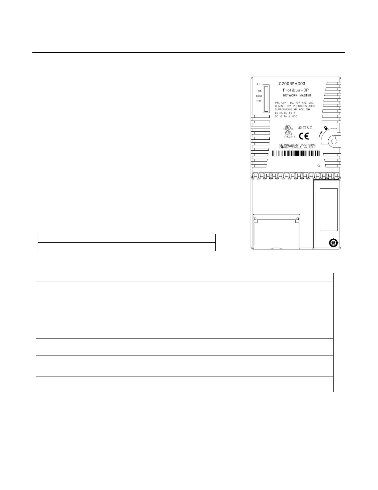
The VersaMax* IC200BEM003 PROFIBUS Master Module allows a VersaMax
CPU005, CPUE05 or PROFINET Scanner (PNS) to send and receive data on a
PROFIBUS-DP V1 network.
The PROFIBUS Master module provides the following PROFIBUS
communications features:
Supports all standard data rates
Supports a maximum of 3,584 bytes of input data and 3,584 bytes of output
data with a VersaMax CPU; a maximum of 1440 bytes of input data and 1440
bytes of output data with a PNS.
Supports a maximum of 125 PROFIBUS-DP slaves, with a maximum of 244
bytes of input data and 244 bytes of output data for each slave
Supports Sync and Freeze modes
Supports DP-V1 Read, Write and Alarm messages
Has PROFIBUS-compliant module and network status LEDs
This module must be located in a VersaMax Communications Carrier.
The PROFIBUS module receives its firmware upgrades indirectly from the
head end CPU or PNS using the WinLoader software utility. WinLoader is
supplied with any updates to the PROFIBUS module software.
Ordering Information
IC200BEM003
VersaMax PROFIBUS Master Module
IC200CHS006
VersaMax Communications Carrier
PROFIBUS support
PROFIBUS-DP V1
Power Consumption
450mA at +5V
I/O Data
With a CPU
A maximum of 3584 bytes of input data and 3584 bytes of output data
With a PNS
A maximum of 1440 bytes of input data and 1440 bytes of output data
With either CPU or PNS head end, a maximum of 244 bytes of input data and 244
bytes of output data for each slave.
PROFIBUS network addresses
0 to 125, software-configurable
Maximum no. of slave devices
125
Network data rate
9.6K up to 12 Mbaud (bit/sec)
Status information
Slave Status Bit Array Table
Firmware Module Revision
Slave Diagnostic Address
Module isolation
Network to Frame ground: 250VAC continuous, 1500VAC for 1 min
Profibus network to backplane: 1500VAC minimum
IC200BEM003
GFK-2739 PROFIBUS Master Module
April 2012
Specifications
For product standards, general operating specifications, and installation requirements, refer to the VersaMax I/O Modules
Manual, GFK-1504.
*
indicates a trademark of GE Intelligent Platforms, Inc. and/or its affiliates. All other trademarks are the property
of their respective owners.

2 PROFIBUS Master Module
GFK-2739
Installation in Hazardous Areas
The following information is for products bearing the UL marking for Hazardous Locations or ATEX marking for
explosive atmospheres:
EQUIPMENT LABELED WITH REFERENCE TO CLASS I, GROUPS A, B, C & D, DIV. 2 HAZARDOUS LOCATIONS IS
SUITABLE FOR USE IN CLASS I, DIVISION 2, GROUPS A, B, C, D OR NON-HAZARDOUS LOCATIONS ONLY
Equipment labeled with II 3 G is suitable for use in Group 2 Category 3 environments.
WARNING - EXPLOSION HAZARD - SUBSTITUTION OF COMPONENTS MAY IMPAIR SUITABILITY FOR CLASS I,
DIVISION 2;
WARNING - EXPLOSION HAZARD - WHEN IN HAZARDOUS LOCATIONS, TURN OFF POWER BEFORE REPLACING
OR WIRING MODULES; AND
WARNING - EXPLOSION HAZARD - DO NOT DISCONNECT EQUIPMENT UNLESS POWER HAS BEEN SWITCHED
OFF OR THE AREA IS KNOWN TO BE NONHAZARDOUS.
WARNING - EXPLOSION HAZARD - USB PORT IS ONLY FOR USE IN NONHAZARDOUS LOCATIONS, DO NOT
USE UNLESS AREA IS KNOWN TO BE NON-HAZARDOUS.
ATEX Marking
II 3 G Ex nA IIC T4 X 0°C<Ta<60°C
Diagnostic Status Arrays
The starting addresses of these arrays are set in the hardware configuration. For information on using memory mapped
COMMREQs, refer to “Diagnostics” in VersaMax PROFIBUS Master User’s Manual, GFK-2740.
Slave Status Bit Array. This 128*-bit array contains a bit for each slave. If communication with a slave has no errors, the
bit corresponding to the slave (determined by its network address) is set. If the communication has errors or is not
occurring for any reason, the bit is cleared. The Master also maintains its own status in the bit corresponding to its network
address.
Slave Diagnostics ID Array. If diagnostics are pending, the first word of this two-word array contains the station address
of the first slave that has diagnostics. The diagnostics can be read using the Get Device Diagnostics COMMREQ
(command 4). This clears the word and the master then places the next pending diagnostic address into the Slave
Diagnostics word. If this word is zero there are no pending diagnostics. The second word of this array is reserved and set
to 0.
DPV1 Alarm Status Array. The 32-bit DPV1 Alarm Status array is used at the beginning of a scan to receive the station
address of a slave that has sent a DPV1 Alarm message. If another slave has sent a DPV1 alarm message, it is ignored
until the first one has been serviced, and will then appear in a subsequent scan.
Slave Configured Bits. This 128-bit array indicates which slaves on the PROFIBUS network are configured. Each slave
has a corresponding bit in this array. A slave's configuration status address equals Start Address + Station Address of the
slave.
Slave Diagnostic Bits. This 128-bit array indicates which slaves on the PROFIBUS network have diagnostic data
available. The diagnostics can be read using the Get Device Diagnostics COMMREQ (command 4).
Each slave has a corresponding bit in this array. A slave's diagnostic status address equals Start Address + Station
Address of the slave.
PROFIBUS Master Module LEDs
On initial powerup with no configuration stored, the LED display should be as shown on page 3. For details on the Master
module’s LED operation, refer to the VersaMax PROFIBUS Master User’s Manual, GFK-2740.
 Loading...