

GE VAT2000 Instruction Manual

GE Power Controls
AC SPEED CON T R O L EQU IPMENT
VAT2000
3ph 200V-230V System 0.4 to 45kW
3ph 380V-480V System 0.4 to 55kW
INSTRUCTION MANUAL
---------------------------------
NOTICE
------------------------------------------
1. Read this manual thoroughly before using the VAT2000, and store in a safe place for reference.
2. Make sure that this manual is delivered to the final user.
3. The contents of this manual can be changed without notice
GE POWER CONTROLS
PCST-3251E-R2

- i -
Contents
Preface .................................................................................................................... iii
PRECAU TIO NS FOR SAFETY ................................................................................ iv
<Names o f ea ch part> ............................................................................................ viii
Chapter 1 Delivery Inspection and Storage ......................................................... 1-1
1-1 Deliver y in sp ec tion and st o rage ..................................................................... 1-1
1-2 Details of rating nameplate and catalogue numbers ...................................... 1-1
Chapter 2 Installation and Wiring ......................................................................... 2-1
2-1 Installation environment ................................................................................. 2-1
2-2 Installation...................................................................................................... 2-2
2-3 Precautions for power supply and motor wiring ............................................. 2-3
2-4 Precautions for wiring to the control signal ..................................................... 2-8
Chapter 3 Test Operation and Adjustment .......................................................... 3-1
3-1 Control selection ........................................................................................... 3-2
3-2 Selection of operation mode .......................................................................... 3-2
3-3 Flow of t est op e ra t ion .................................................................................... 3-3
3-4 Preparation for operation ............................................................................... 3-4
3-5 Settings of data before operation ................................................................... 3-4
3-6 Automatic tuning ........................................................................................... 3-4
3-7 Test op e rat ion w it h op e ra t ion pa ne l ...............................................................3-15
Chapter 4 Operation Panel .................................................................................... 4-1
4-1 Details of operation panel .............................................................................. 4-1
4-2 Modes and parameters ................................................................................. 4-3
4-3 Changing modes ...........................................................................................4-12
4-4 Reading parameters in monitor mode ...........................................................4-13
4-5 Reading and adjusting block-A, B & C parameters ........................................4-14
4-6 Readin g th e c ha nge d pa r ameters (N on - def a u l t v a lue pa rameter lis t) ............4-16
4-7 Customising block-B, C parameter ...............................................................4-18
4-8 Reading fault history.......................................................................................4-20
Chapter 5 Control Input / Output .......................................................................... 5-1
5-1 Input / Output Terminal Function .................................................................. 5-1
5-2 Control Inpu t/ Output Circuit ........................................................................ 5-2
5-3 Programmable sequence input function (PSI) .............................................. 5-3
5-4 Programmable sequence output function (PSO) .......................................... 5-7
5-5 Sequence input logic ..................................................................................... 5-8
5-6 Changing of terminal functions ...................................................................... 5-9
5-7 Programmable analog input function (PAI) ....................................................5-11
5-8 Programmable analog output function (PAO) ................................................5-13
5-9 Selecting the setting data .............................................................................. 5-14

- ii -
Chapter 6 Control Functions and Parameter Settings ........................................ 6-1
6-1 Monitor parameters ....................................................................................... 6-1
6-2 Block-A parameters ....................................................................................... 6-5
6-3 Block-B parameters ....................................................................................... 6-7
6-4 Block-C parameters ......................................................................................6-20
6-5 Funct io n ex p lan a t io n .....................................................................................6-32
6-6 Applic a t ion to sq u are low variab le to rqu e lo ad ...............................................6-72
6-7 Adjusting the vector control speed control related parameters .......................6-75
Chapter 7 Options ................................................................................................. 7-1
7-1 Outlin e of op t ions .......................................................................................... 7-1
7-2 VAT2000´s Main options .............................................................................. 7-4
7-3 Built-in PCB option ....................................................................................... 7-5
7-4 Dynamic braking (DBR).................................................................................. 7-6
7-5 Electromagnetic compliance, EMC ............................................................... 7-9
Chapter 8 Maintenance and Inspection ................................................................ 8-1
8-1 Inspec t ion items ............................................................................................ 8-1
8-2 Measuring devices ........................................................................................ 8-2
8-3 Protective functions ....................................................................................... 8-3
8-4 Troubleshooti ng with fault display .................................................................. 8-4
8-5 Troubl eshooting with no fault display ............................................................. 8-8
Appendix 1 Type Description System................................................................... A-1
2 Outline Dim en s i on Dr aw ings ............................................................ A-8
3 Fault Codes ........................................................................................ A-9
4 7-segmen t LE D Dis p l ay .....................................................................A-11

- iii -
Preface
Please read this manual thoroughly before use, and keep the manual at hand for later
reference. Also make sure that this manual is delivered to the final users.
WARNING
ALWAYS READ THIS MAN UAL THOROUGHLY BEFORE USIN G THE VA T20 00
THIS INVERTER CONTAINS HIGH VOLTAGE CIRCUITS THAT MAY BE FATAL TO
HUMANS. USE EXTREME CAUTION DURING INSTALLATION. MAINTENANCE MUST
BE PERFORMED BY QUALIFIED TECHNICIANS, AND ALL POWER SOURCES MUST
BE DISCONNECTED BEFORE ANY MAINTENANCE. SUFFICIENT NOTICE MUST BE
GIVEN TO THE GEN ERAL OP ERATOR S AND WORKERS B EFOR E S TAR TIN G.
•
ELECTRIC SHOCK MAY OCCUR IF THE FOLLOWING POIN TS ARE NOT OBSERVED
.
•
DO NOT OPEN TH E OU TER-COV ER ( FRONT C OVER) WHILE THE POWER IS ON.
•
A CHARGE STILL REMAINS IN THE INVERTER WHILE THE INDICATOR IS LIT
EVEN IF THE POWER HAS BEEN TURNED OFF. DO NOT OPEN THE OUTERCOVER (FRONT COVER) IN THI S CASE. WAIT AT LEAST 10 MINUTES AFT ER TH E
INDICATOR GOES OU T.
•
DO NOT CONTACT THE ELECTRICAL CIRCUIT WHILE THE CHARGE LAMP ON
THE PCB IS LIT. PERFORM SERVICING, ETC., AFTER WAITING AT LEAST 10
MINUTES AFTER THE LAM P GOE S OU T.
•
ALWAYS GROUND THE INVERTER CASE. THE GROUNDING METHOD MUST
COMPLY WITH THE LAW S OF THE COUNTRY WHERE THE INVERTER IS BEING
INSTALLED.
•
THE INVERTER MAY B E DES TROYED IF THE FOLLOW IN G P OIN TS A R E NOT OBSERV ED
.
•
OBSERVE THE INVERTER SPECIFICATIONS.
•
CONNECT ADE QUATE C A BLES TO TH E INPU T/OU TPUT TER M INAL S.
•
ALWAYS KEEP THE INVERTER INTAKE/OUTTAKE PORTS CLEAN, AND PROVIDE
ENOUGH VENTIL ATION .
•
ALWAYS OBSERVE THE CAUTIONS LISTED IN THIS INSTRUCTION MANUAL.
•
THERE MAY BE SOUR C ES OF N OISE AROUND TH IS INVERTE R AND MOTOR DRIV EN BY
THIS INVERTER. CONSIDER THE POWER SUPPLY SYSTEM, INSTALLATION PLACE AND
WIRING METHOD BEFOR E IN STALL A TION .
INSTALL THIS INVER TER AWAY FROM DEVICES THAT H ANDLE MINU TE S IGN ALS, S UCH
AS MEDICAL EQUIPMENT IN PARTICULAR. ALSO SEPARATE THE DEVICES
ELECTRICALLY , AND TAKE SU FFIC IENT N OIS E MEASUR ES .
•
TAKE SUFFICIENT SAFETY MEASURES WHEN USING THIS INVERTER FOR PASSENGER
TRANSPORTATION, SUCH AS IN LIFTS (ELEVATORS).

- iv -
Precautions For Safety
Items to be observed to prev ent physi c al damage and to ensure safe use of this product ar e noted on the
product and in this instruction manual.
•
Please read this instruction manual and encl osed documents before starting operation to ensure
correct usage. Thor oughly understand the device, safety information and prec autions before starting
operation. After reading, always store this m anual where i t can be accessed easily.
•
The safety precautions are ranked as
“DANGER”
and
“CAUTION”
In this instruction manual.
DANGER
:
When a dangerous situat ion may occur if handling i s mistaken
leading to fatal or major injuries
.
CAUTION
: When a dangerous situation m ay occur if handling is mistaken
leading to medium or minor injuries, or phy si c al dam age.
Note that some items described as
CAUTION
may lead to major results depending on the situation. In
any case, import ant inf ormation that must be observed is described.
•
This instruction manual is written on the premi se that the user has an understanding of the inverter.
Installation, operation, maintenanc e and inspection of this product m ust be done by a qualified person.
Even qualified persons must undergo periodic training.
Qualified refers t o satisfying the following condi tions.
ο
The person has thoroughly r ead and under stood this instruction m anual
ο
The person is well versed in the installation, operation maintenance and inspection of this
product, and understands the possible dangers,
ο
The person is inform ed on matters related to starting, stopping, installation, locks and tag
displays, and has been trai ned in the operation and remedi es.
ο
The person has been trained on the maintenance, inspection and repairs of this product.
ο
The person has been trained on pr otective tools used to ensure safet y .
1. Transportation and installation
CAUTION
•
Always transport the product with an appropriate amount according t o the produc ts weight
Failure to observe this could lead to injuries.
•
Install the inverter and brake resistor on non- c om bustible material such as met al.
Failure to observe this could lead to fires.
•
Do not place the product near inflammable items.
Failure to observe this could lead to fires.
•
Do not hold the from cover while transporting the pr oduc t.
Failure to observe this could lead to injuries from dr opping.
•
Do not led conductive materials such as screws or metal pieces and inflammable materi al such as oil
enter the product .
Failure to observe this could lead to fires.
•
Install the product in a place that can withstand t he weight of the product, and follow the i nstr uc tion
manual
Failure to do so could lead t o injur ies from dropping.
•
Do not install and operate an inverter that is damaged or that is missing parts.
Failure to observe this could lead to injuries.
•
Always observe the conditions described i n the instruction manual for the installation environm ent.
Failure observ e this could lead to faults.

- v -
2. Wiring
DANGER
•
Always turn the device’s input power OFF before star ting wiring.
Failure to do so could lead t o elec trical shocks or fires.
•
Carry out grounding that complies with the standards of the country where the inverter is being
install ed. Fail ur e to do so coul d lead to electrical shocks or fires.
•
Wiring must always be done by a qualified elect ri ci an.
Failure to observe this could lead to electrical shocks or fires.
•
Always install the device before starting wiring.
Failure to do so could lead t o elec trical shocks or injuries.
•
Prepare a breaker such as an MCCB that matches the capacity for the inverter’s power supply side
Failure to do so could lead t o fires.
CAUTION
•
Do not connect an AC power supply to the output terminals (U, V, W).
Failure to observe this could lead to electrical shocks or fires.
•
Confirm that the product’s rated volt age and frequency match the power supply voltage and frequency.
Failure to do so could lead t o injur ies or fires.
•
Install an overheating protecti on dev ic e on the dynamic electrical-discharge braking resistor , and shut
off the power with an error si gnal.
Failure to do so could lead t o fires i n the event of abnormal overheati ng.
•
Do not directly connect a resistor to the DC terminals (between L+1, L+2, and L–).
Failure to observe this could lead to fires.
•
Tighten the terminals screws with the designated tightening torque.
Failure to do so could lead t o fires.
•
Correct connect the output side (U, V, W).
Failure to do so could cause the m otor to rotate in reverse and the machine to be damaged
.
3. Operation
DANGER
•
Always install the from cover before tur ning the input power ON. Never remove the cover whil e the
power is ON. There are sections i n the from PCB that are charged with high voltages.
Failure to observe this could lead to electrical shocks.
•
Nev er touch the switches with wet hands.
Failure to observe this could lead to electrical shocks.
•
Nev er touch the inverter’s terminals whil e the inverter power is ON even if the operati on is stopped
Failure to observe this could lead to electrical shocks
•
Selection of the retry function could lead to unexpected restarting when an alarm occurs. The machine
may start suddenly if the power is tur ned ON when the automatic start function is selected Do not go
near the machine.
Failure to do so could lead t o injur ies.
(Design the machi ne so that physi c al safety can be ensured even if the machi ne r estar ts.)
•
The machine may not stop when a stop command is issued if the deceleration stop function is
selected. Prepar e a separat e em er genc y stop switc h.
Failure to do so could lead t o injur ies.
•
Resetting of an alarm while the run signal is input could lead to unexpected restarti ng. Always confirm
that the run signal is OFF befor e r esetting the alarm.
Failure to do so could lead t o injur ies.

- vi -
Continue from previous page
CAUTION
•
The heat sink and dynamic braking resistor ar e heated to high temperatures, so nev er touc h them.
Failure to observe this could lead to burns.
•
Do not block the inverter’s ventilation holes.
Failure to observe this could lead to fires.
•
The inverter operation can easily be set from low speeds to hi gh speed s, so confirm that the operation
is within the tolerable range for the motor or machine before making settings.
Failure to do so could lead t o injur ies.
•
Prepare holding brakes when necessary. Holding is not possible with the inverter’s brake functions.
Failure to do so could lead t o injur ies.
•
Confirm the operation of the motor as a single unit before operating the machine.
Failure to do so could lead t o injur ies or machine damage due to unforeseen mov em ents.
•
Always prepare a safety backup device so that the mac hine is not placed in a hazardous situation
when an error occurs in the inverter.
Failure to do so could lead t o injur ies or machine damage.
4. Maintenance, Inspection and Part Replacement
DANGER
•
Always wait at least 20 minutes after turning t he input power OFF before starting inspect ions. Make
sure that the displ ay s on the oper ation panel have gone out before rem ov ing the f r ont cov er .
Remove the front cover , and confirm that the "CHARGE" LED on the unit has gone out. Also check
that the voltage between term inals L+1 or L+2 and L– is 15V or less before starting the inspections.
(Check with the "CHARGE" LED if t he unit is not provided with the L– terminal.)
Failure to observe this could lead to electrical shocks.
•
Maintenance, inspections and part r eplacement must be done by a designated person.
(Remove all metal accessories such as watches, bracelet s, etc., before starting the work. )
(Always use an insulation measure tool.)
Failure to observe this could lead to electrical shocks and injuries.
•
Always turn the power OFF before inspecting t he m otor or machine . A potential is applied on the
motor terminal ev en when the motor is stopped.
Failure to do so could lead t o elec trical shocks and injuries.
•
Do no use parts other than those designated for t he repl ac em ent parts.
Failure to observe this could lead to fires.
CAUTION
•
Vacuum the inverter with a vacuum cleaner to clean it. Do not use organi c solvents.
Failure to observe this could lead to fires or damage.
5. Others
DANGER
•
Never modify product.
Failure to observe this could lead to electrical shocks or i njuries.
CAUTION
•
Dispose of this product as industrial waste.
- vii -
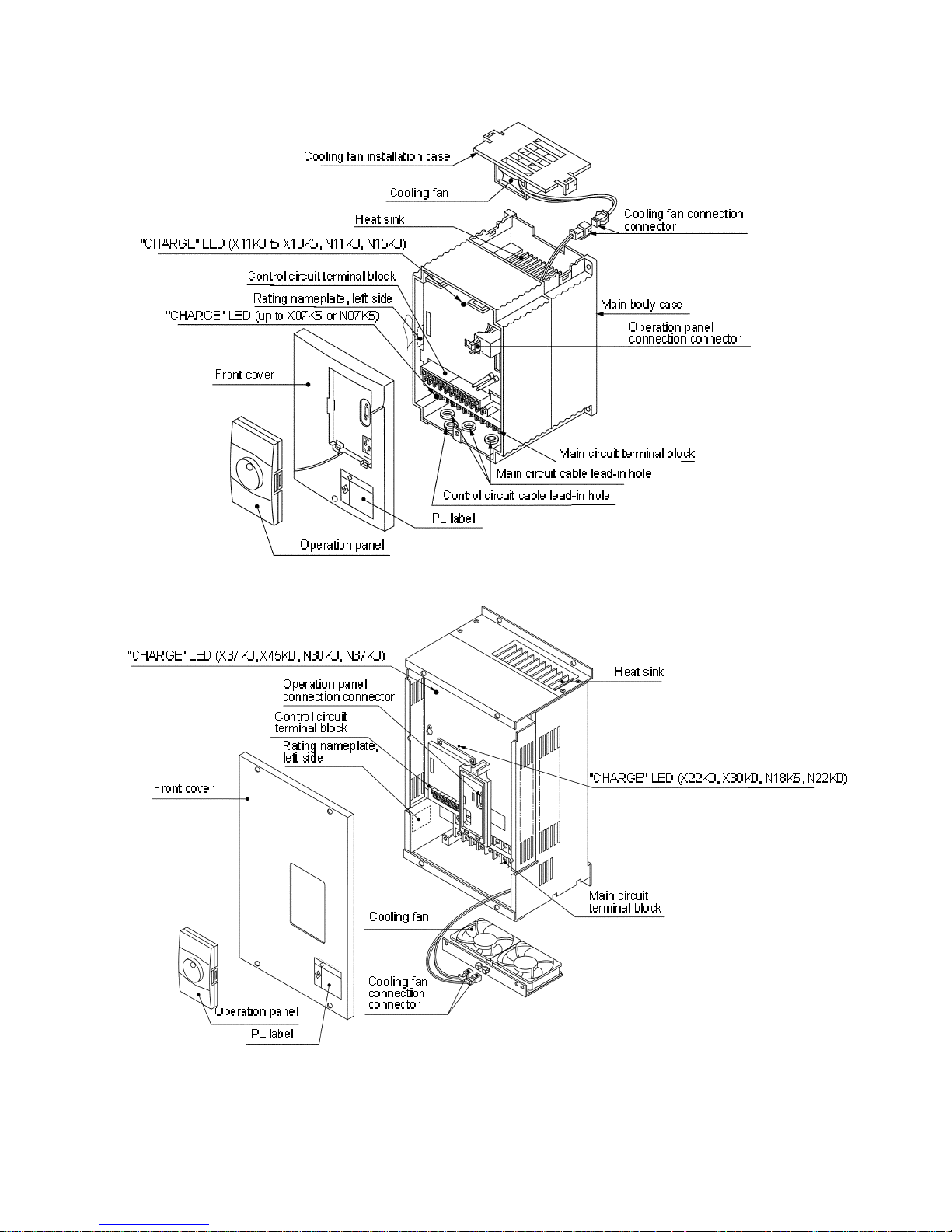
<Names of each part>
For U2KN15K0S, U2KX18K5S and smaller
For U2KN18K5S, U2KX22K0S and larger

1. Delivery Inspection a nd S tora ge
1-1
Chapter 1 Delivery Inspection and Storage
1-1 Delivery Inspection and Storage
1) Remove the inverter from the packaging, and check t he details on the rating nameplate to confirm that
the inverter is as ordered. The rating nameplate is on the left side of the unit.
2) Confirm that the product has not been damaged.
3) If the inverter is not to be used for a while after purchasing, store it in a place with no humidity or
vibration in the packaged state.
4) Always inspect the inverter before using after storing for a long period. (Refer to 8-1.)
1-2 Details of Rating Nameplate and catalogue numbers
1) The following details are listed on the rating nameplate.
CAUTION
CT:
Rating for standard applications (Constant Torque)
VT:
Rating only for Fans and Pu mps (Var iab le To rqu e)
CT/VT settings are described on cha pter 6-6
2) Using the above type as an example, the t ype is d isp layed as follows :
U2K X02K2 S
The VAT2000 can be performed by the user with various optional interface plug-in ca rds. Re fer to Chap te r 7
(PCB Options)
Source vol tage an d capa city
NxxKx: 200V Series
XxxKx: 400V Series
Refer to Appendix for more details
Indicates main circuit options
S: Standard (AC Supply)
D: DC Supply
Refer to chapter 7 (Main Options
MOD. VAT 20 00
INPUT AC3PH
OUTPUT AC3PH
SERIAL NO
U2KX02K2S
CT: 5.4A / VT: 8.6A
380 - 480
380 - 480
0A1234A 1
V 50/60Hz
V 50/60Hz
A
MADE IN JAPAN
2. Installation a nd Wiring
2-1
Chapter 2 Installation and Wiring
CAUTION
• Al ways transport the product with an appropriate amount according to the products weight.
Failure to obser ve this cou ld lead to injuries.
• Install the invert er, dy nami c br aki ng unit and resistor, and other peripheral devices on non-combustible
material such as metal.
Failure to obser ve this cou ld lead to fires.
• Do not place the product near inflammable items.
Failure to obser ve this cou ld lead to fires.
• Do not hold the front cover while trans po rting the product.
Failure to obser ve this cou ld le ad to injur ies from d rop p ing.
• Do not let conductive materials such as screws or metal pieces and inflammable materials such as oil
enter the product .
Failure to obser ve this cou ld lead to fires.
• Install the product in a place that can withstand the weight of the product, and follow the instruction
manual.
Failure to do so could lead to injuries from d ropp ing .
• Do not install and operate an inver ter tha t is da maged or that is missing parts.
Failure to obser ve this cou ld lead to injuries.
• Always observe the conditions descr ibed in the instruction manual for the installation environment.
Failure to obser ve this cou ld lead to faults.
2-1 Installation Environment
Observe the following points when insta lling the in ver ter.
1) Install the in verte r vert ica lly so tha t the w ire lead - in holes face downward.
2) Make sure that the ambient temperature is -10 ºC to 50ºC.
3) Avoid insta llation in the following en viron men t.
• Places subject to direc t sunlight
• Places with oil mist, dust or cotton lint, or subject to salty winds
• Places with corrosive gas, explosive gas or high humidity levels
• Places near vibration sources such as dollies or press machines
• Places made of flammable mat er ials such as wood, or pla c es that are not heat resistant
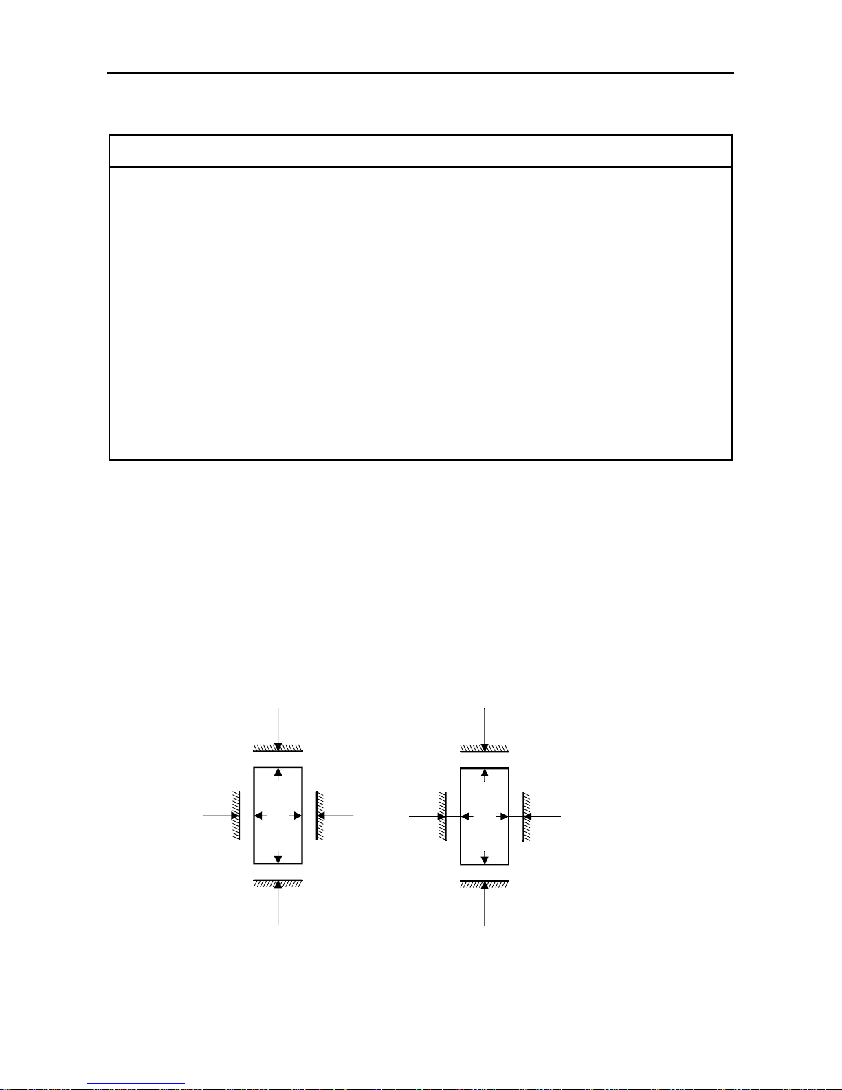
4) Ensure ventilation space around the inverter.
200 mm
50 mm
VAT2000
50 mm
150 mm
200 m m
50 mm
VAT2000
50 mm
200 m m
For N15K0, X18K5 and smaller For N18K5, X22K0 and larger
2. Installation a nd Wiring
2-2
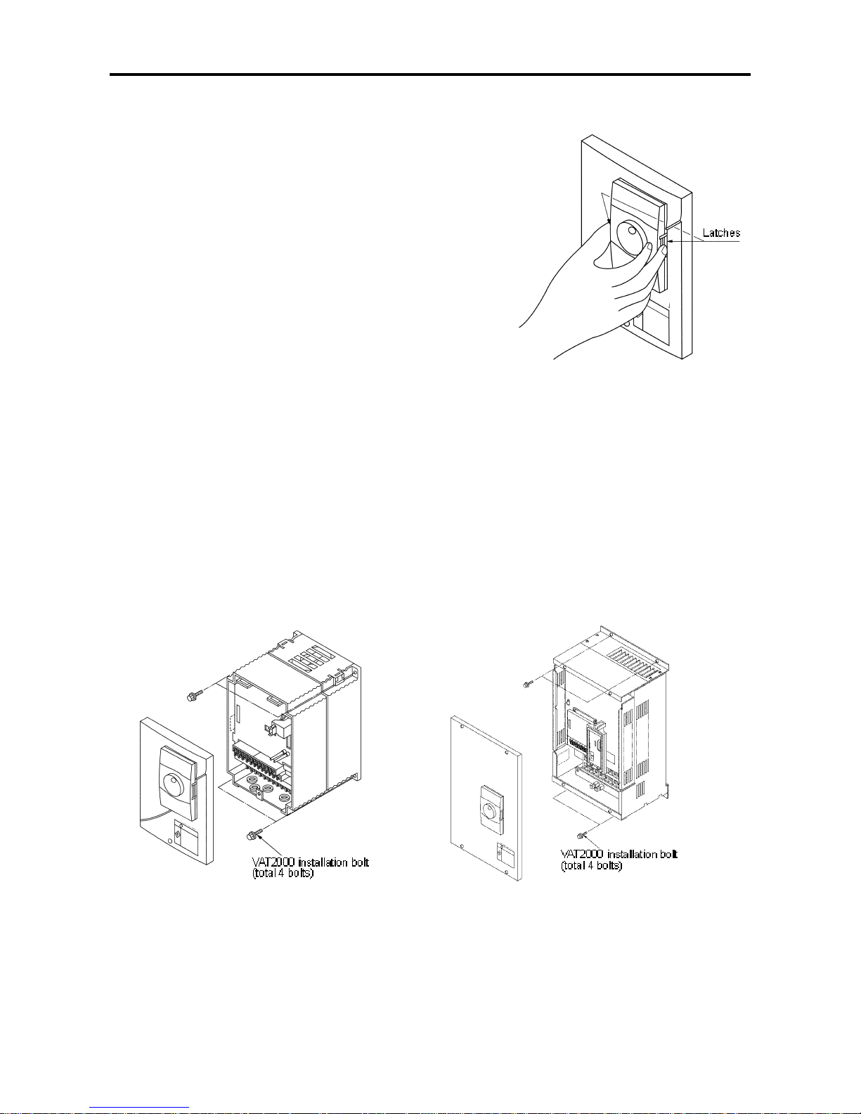
2-2 Installation
Installation and wiring for the N15K0, H18K5 and smaller drives,
and wiring for the N18K5 and X22K0 and larger drives are
carried out with the front cover removed.
Before remo ving the front cover, always remove the opera t ion
panel from the un it. If the fron t co ver is removed without
removing the operation panel, the unit could drop off the
operation panel and be damaged. To remove the operation
panel, press in the left and right latches inw ard and pull of f the
panel as shown on the right.
When the installation and wiring work are completed, install the
front cover, and then ins t a ll the opera tion panel. At that time,
make sure that the latches on the left and right of the operation
panel are securely caught.
Fig 2.2 Fig 2.3
(2) N18K5, X22K0 and larger ( Fi g. 2.3)
Fix the VAT2000 on the fo ur corners, note that
the lower two mounting holes are notched.
These frames weitg more than 25kg, so
installation by two wor kers is re co m mend ed .
(1) N15K0, X18K5 and smaller (Fig. 2.2)
Fix the VAT2000 on the four corners, note that
the lower two mounting holes are notched.
Remove the front cover, and wire to the main
circuit and control terminal block.

2. Installation a nd Wiring
2-3
2-3 Precautions for Power Supply and Motor Wiring
DANG ER
• Always turn the device's input power OFF be fore starting w iring.
Failure to do so could lead to electrical sho cks or fires.
• Carry out grounding that complies with the standards of the country where the inverter is being
installed.
Failure to do so could lead to electrical sho cks or fires.
• Wiring must always be done by a qualified electrician.
Failure to obser ve this cou ld lead to electrical shocks or fires .
• Al ways install the device before starting wiring.
Failure to do so could lead to electrical sho cks or in jur ies.
• Prepare a brea ker su ch as an MCC B or fuses that matches the capa c ity for the in ver ter's pow er supp ly
side.
Failure to do so could lead to fires.
CAUTION
• Do not connect an AC power supply to the out pu t termina ls (U , V, W).
Failure to observe this could lead to injur ies or fires.
• Confirm that the product's rated voltage and frequency match the pow er supp ly voltage and frequency.
Failure to do so could lead to injuries or fires.
• Install an overheating protection device on the dynamic braking resistor, and shut off the power with an
error signal.
Failure to do so could lead to fires in the e vent of abnormal overheat ing.
• Do not directly connect a resistor to the DC terminals (between L+1, L+2 and L–).
Failure to obser ve this cou ld lead to fires.
• Tighten the terminal screws with the designated tightening torque.
Failure to do so could lead to fires.
• Correct connect the output side (U, V, W).
Failure to do so could cause the motor to ro tate in re verse and the machine to be da maged .
Refer to Fig. 2-4 and wire the main ci r c uits for the power supply and motor, etc.
Always observ e the f ollowing pr ec autions for wiring.
CAUTION
There is a risk of electrical shocks.
The VAT2000 has a built-in electrolytic capacitor, so a charge will remain even when the inverter power is
turned OFF. Always observe the following times bef or e carryi ng out wiring work.
• Wait at least 20 minutes after t ur ning the power OFF before starting work. Mak e sure t hat the displays
on the operation panel have gone out before removing the cov er.
• After removing the cover, c onfirm that the "CHARGE" LED at the following position has gone out. Also
check that the volt age between terminals L+1 or L+2 and L– is 15V or less before starting the
inspections. (Chec k with the "CHARGE" LED if the unit is not provi ded with the L– terminal.)

2. Installation a nd Wiring
2-4
Main circuit wiring
a) N07K5S, X07K5S and smaller units
For DC Drives (main option “D”), check Chapter 7-2.
U
DCL
Note 13
)
Note 11
Note 9
)
Note 1
)
Note 8
)
Note 10
)
Note 9
)
Note 7
)
VAT2000
DBR Resistor
76D
L1
L+1 L+2
B
L2
MC
ACL Noise Filter
MCCB
L3
V
W
Power Suppl
y
380-460V
50/60 Hz
MC
Note 13) 76D
Note 14
)
Note 2
)
Note 6
)
Note 5
)
Note 6
)
Note 7
)
Note 3
)
x
M
124
5
6
E3E
b) N11K0S, X11K0S and larg er units
For DC Drives (main option “D”), check Chapter 7-2.
U
DCL
DBR Unit
N o te 1 3
)
N o te 1 2
)
Note 11
)
Note 9
)
Note 4
)
Note 1
)
N o te 8
)
N o te 1 0
)
N o te 9
)
N o te 7
)
VAT2000
DBR Resistor
L1
L+1 L+2 L-
L2
MC
ACL Noise Filter
MCCB
L3
V
W
1
2
3
4
415-480V
380-400V
Power Suppl
y
380-460V
50/60 Hz
MC
N o te 1 2) 76D
N o te 1 4
)
N o te 2
)
N o te 6
)
N o te 5
)
N o te 6
)
N o te 7
)
N o te 3
)
x
M
124
5
6E3
E
Fig. 2.4 Example of main circuit wiring
2. Installation a nd Wiring
2-5
Note 1) Inverter Input / Output t ermin als
The inverter input termi nals are L1, L2 and L3. The output terminal s to the motor are U, V and W.
Do not connect the power supply to the U, V, W terminals. incorrect wiri ng will c ause to inverter
damage or fires.
Note 2) Wire size
For the main circuit wiri ng shown i n Fig. 2-4, use wires recommended in Tabl e 2- 1, including wire
size range, ring terminal and tightening torque. The applicable wire giv en in Table 2-1 is for usi ng
in constant tor que r atings; for variable torque, sel ec t t he wir e giv en for one higher rating, shifting
one column to the right.
Example:
For the X45K0 drive variable torque, use the column of N30K0 drive (for the N37K0
variable torque, use the N37K0 column however)
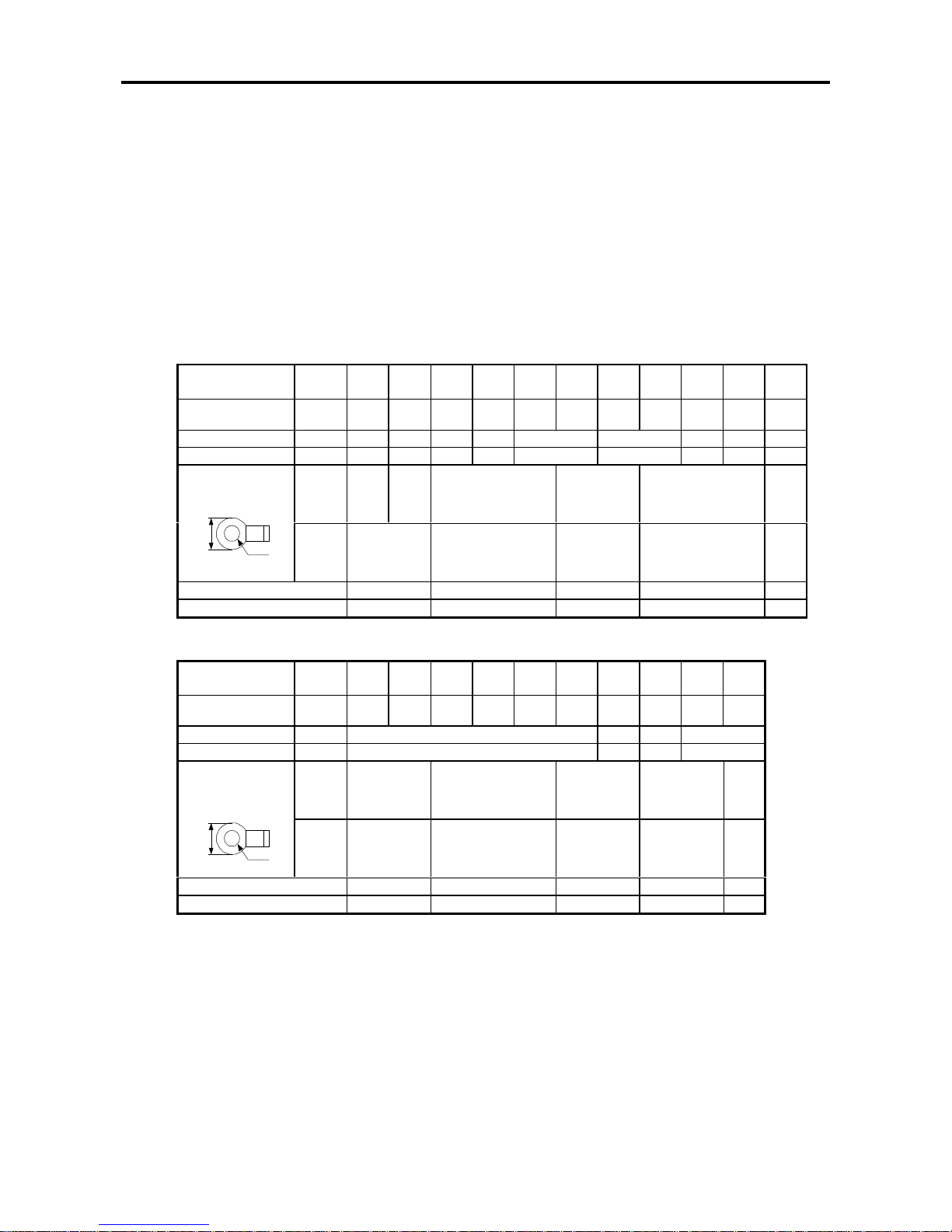
Table 2-1 Applicable wire sizes and t ermin als
a) Power supply and motor wiring (L1, L2, L3, U, V, W, L+1, L+2, L−)
Inverter type
VAT2000
200V
Series
~02K2 04K0 05K5 07K5 11K0 15K0
18K5
22K0
30K0 37K0
400V
Series
~04K0 05K5
07K5
11K0 15K0 18K5 22K0 30K0 37K0
45K0
Applicabl e wire mm
2
2.5 4 6.3 8 16 25 35 60 100
AWG
14 12 10 8 6 4 2 1/0 4/0
d1
8.5 9.5 12 16.5 22 28.5
Max. ring terminal
(mm)
d2
4.3 5.3 6.4 8.4 10.5
Terminal screw
M4 M5 M6 M8 M10
Tightening torque [N•m]
1.224.5918
b) DBR wiring (N07K5, X07K5 and smaller L+2, B) (N11K0, X11K0 and larger L+2, L−)
Inverter type
VAT2000
200V
Series
~02K2 04K0 05K5 07K5 11K0 15K0 18K5
22K0
30K0 37K0
400V
Series
~04K0 05K5
07K5
11K0 15K0 18K5 22K0 30K0 37K0
45K0
Applicabl e wire mm
2
2.5 4 6.3 16
AWG
14 12 10 6
d1
8.5 9.5 12 15 28.5
Max. ring terminal
(mm)
d2
4.3 5.3 6.4 8.4 10.5
Terminal screw
M4 M5 M6 M8 M10
Tightening torque [N•m]
1.224.5918
Note 3) Circuit Breaker for wiring
Install an MCCB or Fuse and MC on the power supply si de of the inverter. Refer to Table 7.2 and
select the MCCB or fuses. UL is meet using ri ght fuse only
Note 4) Rated voltage for auxili ary equipment supply
For the 400 Series(X45K0), wir e the link in power supply termi nal (TB A ) accor ding to the rated
voltage of the power supply being used.
For 380 to 400V, link across 2-3 (factory setting state)
For 415 to 480V, link across 1-2
d2
d1
d2
d1

2. Installation a nd Wiring
2-6
Note 5)
Refer to the appendix 1 for the power suppl y v oltage and frequency, and prepare a power suppl y
suitable for the unit.
Note 6) Power supply capacit y
Make sure that capacit y of the tr ansformer used as the inverter' s power supply is within the
following range. ( For 4% impedance transform er)
Constant torque: 500kVA or less
Variable torque: Capacity that is 10-times or less inverter capacity
If the above values are exc eeded, install an AC Reactor on the inv erter ' s i nput side or a DC
Reactor in the DC stage. ( Refer to chapter 7-5).
Note 7) Noise measures
The inverter will generate high harmonic electrom agnetic noise, so using the following noise
measures is recomm ended. This must be followed for EMC (CE compliance)
a) I nsert a noise filter on the input side of the inver ter. Refer to Table 7-2 and select t he noise
filter.
b) Keep the wiring length bet ween the noise filter and inverter to 30cm or less f or the N00K4 to
N22K0, X00K4 to X30K0, and 50cm or less f or the N30K0 to N37K0, X37K0 to X45K0.
c) Use a shield cabl e for the inverter and motor wiring, and connec t the screen to the inverter ' s
terminal and motor gr ounding terminal.
d) When both control circuit wir ing and main circuit are wired in parallel, keep distance of 30cm
or more, or pass each of the wiring through metal conduits. If the c ontrol c ir c uit wiring and
main circuit wiring intersect, make sure that they intersect at a right angle.
Note 8) Inverter output
a) Do not insert a power factor improvement capacitor on the output side of the inv er ter.
b) When inserting a magnetic c ontactor on the output side of the invert er , prepar e a sequence
control circuit so that the magnetic contactor will open and c lose after the invert er stops.
Note 9) G r ounding
Always wire the inverter’s ground terminal. T he gr ound m ust be according to the regulations of
the Country where the i nv erter is bei ng used .
Note 10) Inverter outpu t surg e vol t age (Fo r 400V Seri es)
The surge voltage applied on the motor side increases depending the output cable lengt h, If this
wiring between mot or and drive exceeds in 30mts, connect a surge absorber exc lusive for the
inverter output .
Note 11) DCL
Always short cir c uit acr oss L+1 and L+ 2 when not using the DCL. (Factory setting stat e)
When connecti ng the opti onal DCL, connect it to L+1 and L+2.
Twist the wiring to t he DCL, and keep the wiring length to 5m or less.
Note 12) DBR unit
When connecti ng the opti onal DB R unit, follow Fig. 2-4 (2) and connect t he L+2 and L– f or 011L,
011H and larger.
The DBR unit and invert er unit will both be damaged if the connection is inc or r ec t.
Twist the wiring to t he DBR unit, and keep the wiring length to 3m or less.
Refer to Section 7-4 f or details.
Note 13) DRB protection
When using the optional DBR unit, use the DBR unit's overload det ec tion relay or insert a thermal
relay (76D) to prot ect the DBR r esi stor and inverter. Prepare a sequence contr ol circuit to turn
OFF the magnetic cont actor (MC) on the input side of the inverter or tri p the wiring breaker
(MCCB) with trip coil using the contact of the DBR unit's overl oad detection relay or it's therm al
relay (76D).
Note 14) Contactor’s coils
Install a surge absorber on the magnetic contactor or relay coils installed near the inverter.

2. Installation a nd Wiring
2-7
(a) U2KN00K4S - U2KN04K0S
U2KX00K4S - U2KX04K0S
(b) U2KN05K5S - U2KN07K5S
U2KX05K5S - U2KX07K5S
(c) U2KN11K0S - U2KN15K0S
U2KX11K0S - U2KX18K0S
(d) U2KX22K0S
(a) U2KN00K4S - U2KN04K0S
U2KX00K4S - U2KX04K0S

2. Installation a nd Wiring
2-8
2-4 Precautions for Wiring to the Control Signal
1) Separate the main cir c uit wiring (to terminals L1, L2, L3, L+1, L+2, L–, B, U, V, W) from the other
drive wires and power wires.
2) Use a 0.25 to 0.75mm² wire for wiri ng to t he contr ol ci r c uit. The tightening torque must be 0.6Nm .
3) Use a twisted pair wire or twisted pair shield wire for wiring the analog signals (as the setters and meter).
(Fig. 2-6.) Connect the shield wire to the TB2 COM terminal of the VAT2000.
The wire length must be 30m or less.
4) The analog output i s dedi c ated f or met eri ng only, such as the speed-meter and amm eter.
It cannot be used for contr ol si gnals such as the feedback control.
5) The length of the sequence input /output contact wir e must be 50m or less.
6) The sequence input (digital I/Os), can be select ed either sink logic or source logic method by the
short pin (W1). Ref er to Table 5-2.
7) Observe the prec autions listed in "Table 5-2 Contr ol input/ output circuit".
8) An example of the control ci r c uit wiring is given in Fig. 2-6.
9) The layout of the cont r ol circuit terminal block is shown in Fig. 2-7; functions are in Table 5-1.
Terminals with t he same t erminal symbol are internally connected.
10) After wiring, always check t he wiring. Do not test control wiri ngs using a megger or buzzer
RESET
COM
AUX
FSI
FSV
P10
20K
+15V
820
Ω
244
Ω
20K
FM
AM
COM
COM
Volta
g
e
output
(0-10 V )
lo ad
max. 1mA
RA
RC
FA
FB
FC
PSO1
PSOE
VAT2000
Max . 1A 250VAC
or 30V DC
Max. 0,4A 250V AC
or 1A 30V DC
Open collector
Max. 30V DC 30mA
0V
0V
EMS
RUN
PSI1
(RRUN)
(FJOG)
(RJOG)
Standa rd Settin
g
PSI2
PSI3
PSI4
PSI5
RYO
RYOV (Note 2)
ANALOG INPUT
DIGITA L INPUT
Frequency
settin
g
(voltage)
2K , 2W
Frequency
Settin
g
(current)
A u x . s e tt in
g
DC ±10V
Common
Ω
Free Voltage input
(5m A per s i
g
nal)
RY24
4.7K
F
A
To co m pl y
with UL
use at
30VAC/DC
or lower
PSO2
PSOE
RY24
RY 24V
PSO3
(Notes)
1. T hree COM termi nals are int er nally connected.
2. No connection shall be made between RY0 and COM since this section is insulated.
3. T his diagr am is an exam p le of the sink log ic c onn ect i on. (Refer to Tabl e 5- 2. )
Fig. 2-6
• Control terminal
(The terminal block i s lai d out in two rows.)
TB1 TB2
RY24 RESET PSI1 PSI2 PSI4 PSO1 PSOE PI0 COM AUX AM FM RC FA
RUN EMS RY0 PSI3 PSI5 PSO2 PSO3 FSV FSI COM COM RA FC FB
Fig. 2-7
1
2
3
W1

3. Test Operation a nd A djustment
3-1
Chapter 3 Test Operation and A dj ustm e n t
DANGER
• Always install the front cover before turning the input power ON. Never rem ov e the cov er whil e the
power is ON. There are sections i n the front PCB that are charged with high voltages.
Failure to observe this could lead to electrical shocks.
• Never touch the switc hes with wet hands.
Failure to observe this could lead to electrical shocks.
• Never touch the inv er ter’s terminals while the inver ter power is ON even if the operation is stopped.
Failure to observe this could lead to electrical shocks.
• Selection of t he r etry function could lead to unexpected r estar ting when a fault occurs. The machine
may start suddenly if the power is tur ned ON when the automatic start function is selected. Do not go
near the machine.
(Design the machi ne so that physi c al safety can be ensured ev en if t he machine restarts.)
Failure to do so could lead t o injur ies.
• The machine may not stop when a stop comm and is i ssued if the decelerati on stop function is selected
and the overvoltage / ov er c urrent limit function is activated. Prepare a separate emergency stop
switch.
Failure to do so could lead t o injur ies.
• Resetting of a fault while the run signal is input could lead to unexpec ted restarting. Always confirm that
the run signal is OFF before r esetting the alarm.
Failure to do so could lead t o injur ies.
CAUTION
• The heat si nk and r esi stor ar e heated to high temperatures, so never touch them.
Failure to observe this could lead to burns.
• Do not block the inverter’s ventilation holes.
Failure to observe this could lead to fires.
• The inverter operation can easily be set from low speeds t o high speeds, so confirm that the
operation i s within the tolerable range for the motor or machine before making setti ngs.
Failure to do so could lead t o injur ies.
• Prepare holding brakes when necessary. Holding is not possible with the inverter’s brake f unc tions.
Failure to do so could lead t o injur ies.
• Confirm the operation of the motor as a singl e unit before operating the machine.
Failure to do so could lead t o injur ies or machine damage due to unfor eseen movements.
Always prepare a safety bac k up dev ic e so that the machine is not plac ed in a hazardous situation
when an error occurs in the inverter.
Failure to do so could lead t o injur ies or machine damage or fires.

3. Test Operation a nd A djustment
3-2
The VAT2000 has several modes of c ontrol. Some of these include settings that must be made according
to the power supply and motor c onstants before actually start ing operation.
The method to set VAT2000 basic operation is explained i n this secti on.
3-1 Control selection
The VAT2000 has five modes of c ontrol, which can be selected with the par am eter ( C30- 0) .
Refer to Appendix 1 Cont r ol Specif ications Table for details.
(1) V /f control (constant torque) (C30-0 = 1) :
(Note 1)
V/f control (voltage – frequency control in constant ratio)
(2) V /f control (variable torque) (C30-0 = 2) :
(Note 1)
V/f control (voltage-frequenc y control in quadratic ratio respect t o a variabl e torque load, such as a
fan or pump)
(3) S peed sen sor-less vector contr ol for standard Induction M otors (C30-0 = 3)
Speed or torque vect or cont r ol of t he IM is achieved without sensor
(4) S peed sen sor vector control f or standard I nduc tion Motors (C30-0 = 4) :
(Note 2)
Speed or torque vect or cont r ol of t he IM is achieved without sensor.
This is used when a high speed accuracy or fast torque response is required.
(5) Permanent Magnet drive c ontrol ( C30- 5 = 5) :
(Note 3)
Speed vector cont r ol for permanent magnet motors (brush-l ess type motors).
The PM motors allow high-efficiency operation in r espect to the standard Induction Mot or s
(Note 1)
The operation panel only displays the parameters required for eac h type control. For example,
when the V/f control is enabled (C30-0 = 1 or 2) the drive will not display the dedicated
parameters for vector control
(Note 2)
An optional PCB (U2K V23 DN1 or DN2) for IM speed de tect ion is nec es s ary. (Tab le 7-1 .)
(Note 3)
An optional PCB (U2KV23DN3) for PM speed detection is necessary. (Ref er to Table 7-1.)
3-2 Selection of operation mode
The VAT2000 operates in both “Local” (from the operation panel) and “Remote” (from I/O terminals)
modes. These modes can be changed with the
+ keys while the motor is stopped. The
selected mode is confi rmed by the LCL LED on the operation panel. Refer to Section 4-1 for details.
For Local Mode : LCL LED ON
Operation is carri ed out from the operation panel.
For Remote Mode : LCL LED OFF
Operation is carri ed out with the terminal block TB1 input t erminals.
CAUTION
Make sure that there is no abnormal noise, smoke or odours at this time.
If any abnormalit y i s found, t ur n the power OF F imm ediately.

3. Test Operation a nd A djustment
3-3
3-3 Flow of Test Operation
Start
↓
Installation and wiring
↓
Initial power supply
↓
Setting of rated items
↓
Automatic Tun ing
↓
Test operation with
operation panel
↓
Setting of parameters
compatible with
external control
↓
Test operation includin
g
external control
↓
End of test operation
Fig. 3.1 Test operation procedure
CAUTION
1. Check that the wiring is correct.
2. The power supply must always be kep t in th e tolerable range.
3. Always check that the inverter rating and motor rating match.
4. Always correctly install the front cover before turning the power on.
5. Assign one worker to operate the switches, etc.
6. Refer to the Chapter 6 and observe the precautions when chan ging the set values such as torque
boost A02-0.
Refer to part 3-4 to 3-6
Refer to part 3-6
Refer to Chapter 5, and perform test operation with
the control inpu t/ou tput fro m the te rmina l block.

3. Test Operation a nd A djustment
3-4
A
%
min
-1
Hz
LCL FW D REV FLT
3-4 Preparation for operation
Always confirm the f ollowing points before turning ON the power after completing wire.
(1) Remove the coupling and belt coupli ng the motor and machine, so that t he m achine can be run as a
single unit.
(2) Confirm that t he power supply wi r e is correctly wired to t he input t erminals (L1, L2, L3).
(3) W hen using the 400V Series (X45K0S), confirm that the auxiliary power supply terminal (TBA) short
right terminals to match the power supply voltage.
For 380 to 400V : Link between 2-3 (fact or y setting)
For 415 to 480V : Link between 1-2
(4) Make sure that t he power supply is within the tolerable range.
(5) Make sure that motor is connected with the correct phase order.
(6) Fix the motor with the specified method.
(7) Make sure that none of the t erminal board screws are loose.
(8) Make sure that t her e is no short cir c uit state in the terminals caused by wire scraps, etc.
(9) Always correctly install the front cov er and outer c ov er before turning the power ON.
(10) Assign an operator, and make sure that the operator operates the swit c hes.
3-5 Settings of data before operation
(1) Turn ON the MCCB, and then turn ON the inverter power.
All LEDs will light m omentar ily on the indicator, and then
"
", " " will display bef or e displ ayi ng " ".
The "LCL" and "Hz" LED will al so li ght.
(2) Refer to Section 4-5, and c onfirm the rating parameters.
3-6 Automatic tuning
Automatic tuning measures the constants of the connected motor, and automatically adjusts the
parameters so that the system is used to their maximum performanc e.
VAT2000 automati c tuning can be carried out independently for each of the following ty pes of c ontrol.
V/f control (constant torque) (C30-0 = 1)
V/f control (vari able torque) (C30-0 = 2)
IM speed sensor-less vec tor control (C30-0 = 3)
IM vector control with speed sensor (C30- 0 = 4)
(Note 1)
All parameters belong blocks “B” and “C” -like parameter C30-0- are not displayed as default.
Check setting in param eter A05-2 prior set parameter C30- 0
(Note 2)
The PM motor control, does not have a specific A utomatic tuning. Refer to 6-8 for details

3. Test Operation a nd A djustment
3-5
3-6-1 V/f control (constant torque) (C30-0 = 1),
V/f control (variable tor que) (C30-0 = 2) automatic tuning
(1) Automatic tuning
The Auto-tuning f or V/f control (constant t orque) or V/f control (v ariable torque) c an be perf ormed i n
two modes, basic or ext ended. The mode selection is allowed by param eter (B19-0).
(Note 1, 2)
1) B19-0 = 1: Mode 1: V/f contr ol basi c adjustment mode (Execution time: approx . 10 seconds).
The drive automati cally adjusts basic parameters, such as boost v oltage and brake v oltage. In
this phase the motor does not rotate.
The following param eters are automatically adjusted by ex ec uting Mode 1.
Table 3-6-1
Parameter No. Name
A02-2
A03-0
B02-0, 1
Manual torque boost sett ing
DC brake voltage
R1: Primary resistance
2) B19-0 = 2: Mode 2: V/f control extended adjustment mode (Exe cu t ion time : appro x. 1 min .). Use this
method if the motor is completely unloaded only. (No load at motor shaft )
The drive automatically adjusts parameters related to the slip compensation and max. torque
boost. In this phase the motor rotate.
The following param eters are automatically adjusted by ex ec uting Mode 2.
Table 3-6-2
Parameter No. Name
A02-2
A03-0
B02-0, 1
A02-5
A02-6
Manual torque boost sett ing
DC brake voltage
R1: Primary resistance
Slip compensati on gain
Max. torque boost gain
(Note 1)
The automatic tuning function (B19-0) cannot be used in modes other than control selected
with the parameter (C30-0). When C30-0 is set to 1 or 2, the following cannot be sel ec ted.
B19-0 = 3: Mode 3: Vector control basic adj ustm ent mode
B19-0 = 4: Mode 4: Vector control extended adjustment mode
(Note 2)
If the base frequency of the motor is applied on a motor exceeding 120Hz, select Mode 1
(B19-0 = 1). Adjust the sli p compensation gain (A02-5) and max. tor que boost gain (A02-6)
manually.

3. Test Operation a nd A djustment
3-6
CAUTION
Precautions for execu t in g V/f con t rol ( con st ant torque) V/f control (variabl e torqu e) automat ic
tuning
• Dur ing automatic tuni ng, t he m otor m ay rot ate, so al ways confirm safety before starting automatic
tuning.
• S epar ate the motor from the load and mac hine, etc., and run the motor as a stand alone unit during
automatic tuning.
• Even when Mode 1 is executed, the motor m ay rot ate due t o vi br ation, etc.
If the vibration is large, turn the
key immediately to stop operati on.
• A lways check the safety on the load si de before executing automatic tuning, regardless of the Mode 1
or 2 setting.
With Mode 2, the motor will aut om atically start rotating.
• If the automatic tuni ng function does not end correctly, always turn the inverter power OFF befor e
investigati ng or c onfirming the operation.
• A utomatic tuning can be carried out only in the Local Mode.
• If the motor has an unstable frequency band, automatic tuning m ay not end normally. In this case, the
maximum torque boost f unc tion cannot be used.
• A lways ground the motor and inv erter .
• If the load is less than 30% and the fluctuat ion does not occur, automati c tuning c an be c ar ri ed out wit h
the load and machine connec ted. However, the performanc e m ay not be complete.
• Always carry out automatic tuning before using the maximum torque boost function.
• The contact output FLT will functi on if the automatic tuning does not end correc tly. In equipment that
uses this contact, keep the operation of the related dev ic es i n mi nd.
3. Test Operation a nd A djustment
3-7
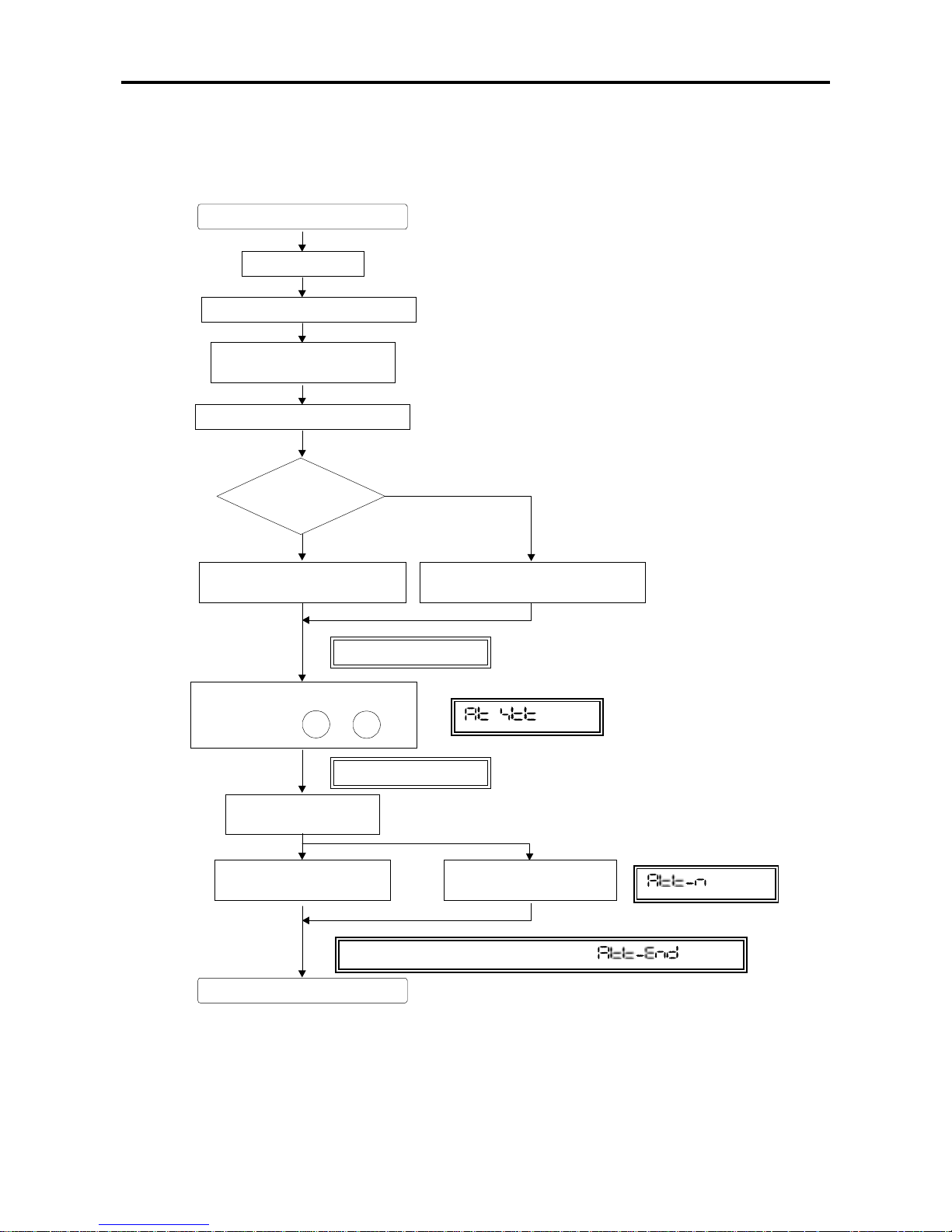
(2) Automatic tuning operatio n p rocedures
The automatic tuning is carried out according the following procedure.
Fig. 3-2 Auto-tuning procedure for V/f control (Constant Torque and Variable Torque)
A u to ma tic tun ing procedures
Automatic Tuning end
(1)
Preparation
Turn power ON, start VAT200 0
(2)
Select control method
C30-0= 1 or 2
(3)
Inicialize m otor constants
“LC L ” LE D B links
“LC L ” LE D B links
Can the motor
rotate?
Y
N
(4)
Input 1 in B19-0, for basic
V/f tunin
g
mode
(6)
Au tomatic tun ing
execution
(7)
Au tomatic tun ing
Normal completion
(5)
Start automatic tunin
g
(4)
Input 2 in B19-0, for extended
V/f tunin
g
mode
FWD
I
REV
I
Pre s s the or ke
y
(8)
Au tomatic tun ing
with erro r completion
“LCD” LED lights stabl e ( not blinking). Display
•
Display
Display

3. Test Operation a nd A djustment
3-8
1) Preparation
Separate the mot or and l oad, mac hine, etc., and confirm the safety on the load side.
2) Selection of control method
• Set A05-2 to 1. (enables parameter display)
• By par am eter (C30-0), select V/f control according the load conditions
V/f control (constant torque) (C30-0 = 1) ( Default value)
V/f control (vari able torque) (C30-0 = 2)
3) Initialisation of motor constants
Input the motor rating nameplate v alue parameters. Automatic tuning will automatically change the
parameters sh own in table 3-6-1 or t able 3- 6-2.
Table 3-6-3
Parameter No. Name
B00-0
B00-1
B00-2
B00-3
B00-4
B00-5
B00-6
B00-7
Rated input voltage sett ing [V]
Max/base frequenc y simple setting [Hz]
Motor rated out put [kW]
Rated output volt age [V]
Max. frequency [Hz]
Base frequency [Hz]
Motor rated current [A]
Carrier frequency [kHz]
* The max. frequency cannot be set below the base f requency, and the base frequency cannot
be set above the max. frequency .
4) Selection of automatic tuning function
• Set A05-0 to 1. (enables parameter display)
• By par am eter (B19-0), select the automatic tuning mode according working conditions. Ref er to
section 3-6-1 for details.
• T he automatic tuning will star when the
key is pressed.
• During the automatic t uning state, the LCL LED will blink.
• T o abor t the automatic tuning, press the
key.
5) Starting automatic tuning
Automatic tuning will start when either the
key or key is pressed according to the
required rotation direction. A message indic ating starting will appear on the operation panel.
To stop, press the
key or input the emergency stop signal (EMS) from the terminal block.
* Keys other than
and are disabled during automatic tuning.
6) Duri ng automatic tuning execution
The progression state can be shown by par ameter display D22-0.
Refer to section 3-6-4 for details.
7) Normal completion of automatic tuning
The "LCL" LED will end blinki ng, lighting stable, and a message indic ating the end will be
displayed. Ref er to section 3-6-1 for the adjustment details.
8) Abnormal completion of automatic tuning
If the automatic tuning ends abnormally, a error message will appear. Check according to the
error codes. Ref er to secti on 3- 6- 3 for details.

3. Test Operation a nd A djustment
3-9
3-6-2 IM speed sensor-less vecto r con t rol (C30-0 = 3) and
IM vector control with sp eed sen sor (C30- 0 = 4) automatic tuning
(1) Automatic tuning
The Auto-tuning for the IM speed sensor-less vector control or IM vect or control with speed sensor
can be performed in two modes, basic or extended. The mode selection is allowed by parameter
(B19-0).
(Note 1)
1) B19-0 = 3: Mode 3: Vector c ontrol basic adjustment mode (Exec ution time: approx. 30 seconds)
The drive automati c ally adjusts basic parameters for v ector control.
The following param eters are automatically adjusted by ex ec uting Mode 3.
Table 3-6-4
Parameter No. Name
B01-8
B02-0, 1
B02-2, 3
B02-4, 5
B02-6, 7
No-load output v oltage
R1 : P rimary resistance
R2 : S ec ondar y r esi stanc e
Lσ: Leakage induct ance
M’ : Excitation inductance
2) B19-0 = 4: Mode 4: Vector c ontrol expanded adjustment mode (Ex ec ution time: approx. 1 minute)
This mode is selected for constant power range operation only.
(Note 2)
The following param eters are automatically adjusted by ex ec uting Mode 4.
Table 3-6-5
Parameter No. Name
B01-9
B02-0, 1
B02-2, 3
B02-4, 5
B02-6, 7
B34-0 to 7
No-load output v oltage
R1 : P rimary resistance
R2 : S ec ondar y r esi stanc e
Lσ: Leakage induct anc e
M’ : Excitation inductance
M variable compensation table
(Note 1)
The automatic tuning function (B19-0) cannot be used in modes other than control selected
with the parameter (C30-0). When C30-0 is set to 3 or 4, the following cannot be sel ec ted.
B19-0 = 1: Mode 1: V/f control basic adjustment mode
B19-0 = 2: Mode 2: V/f control extended adjustment mode
(Note 2)
When the motor works under constant po wer operat ion, the excitation inductance
fluctuation must be compensated.
Assign the operation r ange to the reference speed table in B 33- 0 to 7.
Note that the motor will rotate to the max. speed in this case, so take special c ar e to safety.

3. Test Operation a nd A djustment
3-10
CAUTION
Precautions for execu t in g IM sp eed sen sor-less vector control or IM vector control wi th speed
sensor automati c tuning
• Dur ing automatic tuni ng, t he m otor m ay rot ate, so al ways confirm safety before starting automatic
tuning.
• S epar ate the motor from the load and mac hine, etc., and run the motor as a stand alone unit during
automatic tuning.
• The motor may vibrate and rotate during automatic tuning.
If the vibration is large, turn the
key immediately to stop operati on.
• A lways check the safety on the load si de before executing automatic tuning. The motor will
automatic ally star t rotating during automati c tuning.
• If the automatic tuni ng function does not end correctly, always turn the inverter power OFF befor e
investigati ng or c onfirming the operation.
• A utomatic tuning can be carried out only in the Local Mode.
• A lways ground the motor and inv erter .
• If the load is less than 10% and the fluctuation does not occur, autom atic tuning can be carried out with
the load and machine connec ted. However, the performanc e m ay not be complete.
• The contact output FLT will function if the automatic tuni ng does not end correc tly. In equipment that
uses this contact, keep the operation of the related dev ic es i n mi nd.

3. Test Operation a nd A djustment
3-11
(2) Automatic tuning operatio n p rocedures
The automatic tuning is carried out according the following procedure.
Fig. 3-3 Automatic tuning procedures for senso r or sen sorl ess vect or control (for
Induction motors)
* The Speed regulator (ASR) must be
manuall
y
adjusted in Vector Control
“LCD” LED lights stabl e ( not blinking). Display
•
Display
Display
A u to ma tic tun ing procedures
Automatic Tunin
g
end
(1)
Preparation
Turn power ON, start VAT200 0
(2)
Select control method
C30-0= 3 or 4
(3)
Initialize motor consta nts
“LC L ” LE D B links
“LC L ” LE D B links
Constant output
operation
N
(4)
Input 3 in B19-0, for basic
Vector control tunin
g
mode
(6)
Au tomatic tun ing
execution
(9)
Set and adjust
accordin
g
to system
(7)
Au tomatic tun ing
Normal completion
(5)
Start automatic tunin
g
(4)
Input 4 in B19-0, for extended
Vector Control tunin
g
mode
FWD
I
REV
I
Pre s s the or ke
y
(8)
Au tomatic tun ing
with erro r completion
Y

3. Test Operation a nd A djustment
3-12
1) Preparation
Separate the mot or and l oad, mac hine, etc., and confirm the safety on the load side.
2) Selection of control method
• Set A05-2 to 1. (enables parameter display)
• By par am eter (C30-0), select V/f control according the load conditions
IM speed sensor-less vec tor control (C30-0 = 3), ( Default value)
IM vector control with speed sensor (C30-0 = 4)
* The default value is V/f control ( c onstant torque) (C30-0 = 1).
3) Initialisation of motor constants
Input the motor rating nameplate value parameters. Automatic tuning will automatically change the
parameters, so it is re co mmended to write down the values se t in tab le 3-6-4 or table 3-6-5.
Table 3-6-6
Parameter No. Name
B01-0
B01-1
B01-2
B01-3
B01-4
B01-5
B01-6
B01-7
B01-8
Rated input voltage sett ing [V]
Motor rated out put [kW]
No. of motor poles [Pole]
Rated output volt age [V]
Max. speed [min
−
1
]
Base speed [min
−
1
]
Motor rated current [A]
Carrier frequency [kHz] :
(Note 1)
No. of encoder pulses [P/R] :
(Note 2)
* When the motor works under constant power operat ion, the excitation induct ance fluctuation
must be compensated.
Assign the operation r ange to the table reference speed in B 33- 0 to 7.
Note that the motor will rotate to the max. speed in this case, so take special c ar e to safety.
* The max. speed cannot be set below the base speed, and the base speed cannot be set
above the max. speed.
(Note 1)
During IM speed sensor-less vector control (C30-0 = 3), it is recommended to set the
carrier frequency to 10KHz to improve the current detection accuracy.
(Note 2)
Always enter encoder pulse numbers when using the speed sensor.
4) Selection of automatic tuning function
• Set A05-0 to 1. (enables parameter display)
• By par am eter (B19-0), select the automatic tuning mode according working conditions. Ref er to
section 3-6-1 for details.
• T he automatic tuning will star when the
key is pressed.
• During the automatic t uning state, the LCL LED will blink.
• T o abor t the automatic tuning standby state, press the
key.

3. Test Operation a nd A djustment
3-13
5) Starting automatic tuning
Automatic tuni ng will start when the
key or key is pressed according t o the required
rotation dir ection. A message indicating star ting will appear on the operation panel.
To stop, press the
key or input the emergency stop signal (EMS) from the terminal block.
* Keys other than
and are disabled during automatic tuning.
6) Duri ng automatic tuning execution
The progression state can be conf irmed with D22-0.
Refer to section 3-6-4 for details.
7) Normal completion of automatic tuning
The "LCL" LED will end blinki ng, lighting stable, and a message indic ating the end will be
displayed. Ref er to section 3-6-2 for the adjustment items.
8) Abnormal completion of automatic tuning
If the automatic tuning ends abnormally , a message will appear. Investigate and check according
to the error codes. Refer to section 3-6-3 for detail s on the error c odes.
9) Additional settings and adjustments
There are some parameter r elated to load condition or requir ed r esponse control which shoul d be
adjusted manually. The main parameters are shown below.
• A10- 0: ASR response : Set the speed control response in [r ad/s] unit.
If the speed tracki ng is slow, i nc r ease this value.
Note that if this val ue is too high, hunting may occur.
• A10- 1: Machine time constant 1 : Set the time required t o accelerate from zero to the base
speed with the rated torque.
Tm [msec] = 10.968 × J [kgm
2
] × N base [min
−
1
]/Power [W]
J : Total inertia [kgm
2
]
N base : Base speed [min
−
1
]
• A10- 2: Integral tim e constant c om pensation coefficient:
Increase the com pensation coefficient if the
overshooting is hi gh dur ing speed control.
• A10- 3: ASR drive torque limit : Increase if a higher driv e torque is required.
• A10- 4: ASR regenerative torque lim it : Increase if a higher r egener ative torque is
required.
9) Adjustment for Induction Motor, sensorless vector control
Adjust the following items, to improve accuracy
•
Fine adjustment of primary resistance
With motor unloaded, run the motor at the minimum speed to be used, and finely adjust the
primary resistance (B02-0,1). For Forward run, adjust so that D11-4 (ASR output) is near zero
on the positiv e side. ( Note that B02-0 can be set during run but B20-1 can not)
Make sure that the D11-4 does not reach t he negative side during forward run.
•
Adjustm e nt of es t im a t e d s pe e d integral gain
Confirm that D00-3 (motor speed on % units) is stable (±1% or less) during trial operation. If not
decrease (approx. half) the speed estimated pr opor tional gain (B31-1)
 Loading...