

Page 1

GE Power Controls
VARIABLE SPEED DRIVE UNIT
INVERTER
VAT20
1ph 200V-240V system, 0.2-0.75kW
1ph/3ph 200/240V system, 1.5-2.2kW
3ph 380/460V system, 0.75-2.2kW
INSTRUCTION MANUAL
------------------------------------------------------------ NOTICE ---------------------------------------------------------------
1. Read this manual thoroughly before using the VAT20, and store
in a safe place for reference.
2. When using this speed drive unit in the EU, compliance with the EMC Directive
(89/336/EEC) is required. Check carefully Chapter 2.4. - Installation.
3. The contents of this manual can be changed without notice
Copyright GE Industrial Systems, GE Power Controls, January 2004
1
Page 2

VAT20
Table of Content s
Foreword.....................................................................................3
Chapter 1 Safety Precautions
1. Precautions of operation......................................... 4
2. Precautions of operation environment....................7
Chapter 2 Hardware Instruction and Installation
1. Operation environment........................................... 8
2. Type number definitions.........................................9
3. Specifications.......................................................10
4. Wiring...................................................................12
5. Dimensions & terminal block layout...................... 18
Chapter 3 Software Index
1. Control panel instructions..................................... 23
2. List of parameters................................................. 24
3. Parameter function description............................. 25
4. Malfunction Indication and countermeasure......... 36
5. General troubleshooting method .......................... 39
Chapter 4 Maintenance and Periph erals
1. Maintenance and examinator............................... 47
2. Voltage current measurement .............................. 48
3. Input AC reactor specifications.............................49
4. EMC filter (class B) specifications........................ 49
5. DIN-rail specifications........................................... 49
6. Dynamic braking resistor specifications................49
2
Page 3
1. Foreword
To fully employ all functions of the inver ter, and to en sure the safety of users, please read through
this operating manual in detail. Should you have any further query, please feel free to contact your
local distributor or customer service of GE.
Precaution
The inverter is a power electronic device, for safety reason, please take special care for
paragraphs with “WARNING” or “CAUTION” symbol. They are important safety precautions to be
aware of while transporting, installation, operating or examining the inverter. Please following
these precaution to ensure your safety.
WARNING
CAUTION
Personnel injury may be resulted by improper operation.
The inverter or mechanical system may be damaged by improper operation.
WARNING
● Do not touch the PCB or components on the PCB right after turning off the power before the
charging indicator went off.
● Do not attempt to wire circuitry while power is on. Do not attempt to examine the components
and signals on the PCB while the inverter operating.
● Do not attempt to disassemble or modify internal circuitry, wiring, or components of the
inverter.
● The grounding terminal of the inverter must be grounded properly with 200V class type III
standard.
● This is a product of the restricted sales distribution class according to EN 61800-3.
In a domestic environment this product may cause radio interference in which case the user
may be required to take adequate measures.
CAUTION
● Do not attempt to proceed dielectric strength test to internal components of the inverter.
There are sensitive semiconductor-devices vulnerable to high voltage in the inverter.
● Do not connect the output terminals: T1(U), T2(V), and T3(W) to AC power outlet.
● The CMOS IC on the primary PCB of the inverter is vulnerable to static electrical charges.
Do not contact the primary PCB of the inverter.
2. Examination bef o re installat ion
Every GE Power Controls inverter has been fully tested and examined before shipment.
Please carry out following examination procedures after unpacking your inverter.
● Check to see the model number of the inverter. It should be the one that you ordered.
● Check to see if there is any damage during the transportation. Do not connect the inverter
to the power supply if there is any sign of damage.
Report to regional sale representative if you find any abnormal condition as mentioned above.
3
Page 4
Chapter 1. Safety Precautions
1.1. Precautions of operation
Before turning ON power
CAUTION
Choose appropriate power source with correct voltage setting as the input voltage
specification of the inverter.
WARNING
Special care must be taken while wiring the primary circuitry panel. The L1 and L2
terminal must be connected to input power source and must not be mistakenly
connected to T1, T2 or T3 terminal. This may damage the inverter when the power is
turned on.
CAUTION
l Do not attempt to transport the inverter by the front cover. Securely hold the inverter
by the heat-sink mounting chassis to prevent the inverter from falling that may cause
personnel injury or damage the inverter.
l Install the inverter onto firm metal base or other inflammable material. Do not install
the inverter onto or nearby any flammable material to avoid fire.
l Additional cooling fan should be installed if several inverter are installed into one
control panel to lower the temperature inside below 40° to avoid overheating or fire
alarm.
l Turn off power supply before proceeding removal or installation of operating panel.
Carry out installation procedure according to instructions given to avoid poor-contact
situation resulting operating panel malfunction or no displaying information.
l Suitable for use on a circuit capable of delivering not more than 5000RMS
symmetrical amperes, 240V maximum
l Not proved with over speed Protection or equivalent
l Only intended for use in a pollution degree 2 macro environment or equivalent
4
Page 5

When power is turned ON
l Do not attempt to install or remove connector of inverter when the power supply is
turned on. Otherwise, the inverter may be damaged due to the surge peak caused
by the insertion or removal.
l When momentary power loss is longer than 2 seconds (the large of horse power,
the longer of time), the inverter does n ot have enough s torage power to control the
circuit. Therefore, when power is regenerated, the operation of the inverter is
based on the setup of F_10 and the condition of external switch, this is considered
to be ‘restart’ in the following paragraphs.
l When the momentary power loss is short, the inverter still has enough storage
power to control the circuit; therefore, when power is regenerated, the inverter will
automatically start operation again depends on the setup of F_23.
When restart the inverter, the operation of the inverter is based on the setup of
F_10 and the condition of external switch (FWD/REV button). Attention: the
restart operation is irrelevant with F_23/F_24.
(1) When F_10=0, the inverter will not start after restart.
(2) W hen F_10=1 and the external switch (FW D/REV button) is OFF, the inverter
will not start after restart.
(3) When F_10=1 and the external switch (FWD/REV button) is ON, the inverter
will start automatically after restart. Attention: Base on safety reason, please
turn off the external switch (FWD/REV button) after power loss to avoid
possible damage to the machine and the human body after sudden
regeneration of power.
WARNING
Under Operatio n
Do not switch ON or OFF motor at the middle of operation. Otherwise, the inverter
over-current break-down may be resulted.
l Do not remove the front cover of the inverter when the power is ON to avoid
personnel injury caused by electrical shock.
l When the automatic restart function is enabled, the motor and machinery will be
restarted automatically after fully stop from operation. Do not get close to the
machinery to avoid personnel injury.
WARNING
WARNING
5
Page 6

l Do not touch the heat-sink base.
l The inverter can be easily operated from low-speed to high-speed range. Please
reconfirm the operating range of motor and machinery.
l Do not examining the signals on the PCB of the inverter when it is under operation.
l All inverter had been properly adjusted before delivery. Do not attempt to adjust it.
Do not proceed with disassemble or examination procedure before ensuring that the
power is off and the Power LED extinguished.
During examinatio n and maintenance
CAUTION
CAUTION
CAUTION
Inverter environment should be within temp: –10 OC ~ +40 OC, humidity under 95% RH
without condensing.
CAUTION
After the removal of shield sticker, the environment temperature should be within
O
C and +50OC and humidity under 95% RH without condensing. Besides, the
-10
inverter should be free from water dripping or metal dust.
6
Page 7

1.2. Precautions of operation environment
oil
Avoid direct sunlight
Keep away from
corrosive gas or liquid
Keep away from salty
environment
Keep away where rain or
dripping water may get
into the inverter
Keep away from oil
grease and gas
Avoid metal dust and
dusty environment
Avoid massive vibration
Avoid heat
Keep away from high
electrical-magnetic wave
or ultra-high wave.
Keep away from
radio-active matter
7
Avoid where environment
temperature is too high
Keep away from
flammable material
Page 8
Chapter 2. Hardware Instruction and Installation
2.1. Operation Environment
The installation site of the inverter pose direct impact to the fully functionality and the life-span
of your inverter. Please carefully choose the installation site to meet following requirements:
l Mount the unit vertically
l Environment temperature: -10
l Avoid placing close to any heating equipment
l Avoid water dripping or humid environment
l Avoid direct sunlight
l Avoid oil or salty corrosive gas
l Avoid contacting corrosive liquid or gas
l Prevent foreign dusts, flocks, or metal scraps from entering interior
l Away from radioactive matter or flammable material
l Avoid electric-magnetic interference (soldering or power machinery)
l Avoid vibration, if vibration can not be avoided, anti-rattler should be installed to reduce it.
l If inverter is installed in control panel, please tear off shield sticker of VAT20.
Correct alignment Correct alignment
Additional cooling fan should be installed to lower the environment below 50
Cooling fan
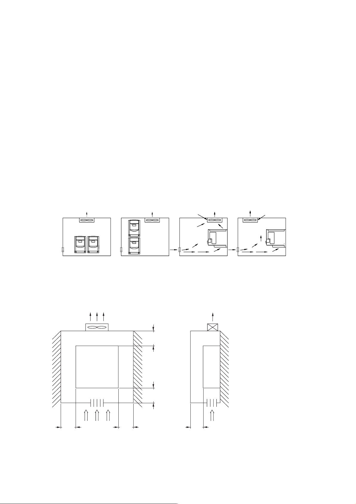
Correct alignment Wrong alignment Wrong alignmentCorrect alignment
l Installation of the inverter must place the front side of inverter facing front and the top of
inverter towards up direction for better heat dissipation.
l Installation rooming must be compliant to following requirement.
O
C to +50OC
Cooling fan
Cooling fan
Cooling fan
O
C
q
< 50°C
(1)
12 cm
(min)
VAT 2 0
Installation
direction
12 cm
(min)
12 cm
(min)
Ventilation
(2) (2)
Front view
(1) Maximum temperature in the enclosure 50°C
(2) Keep 7 cm for following drives: N1K5, N2K2, X0K7, X1K5, X2K2
12 cm
(min)
5 cm
(min)
Side view
8
Page 9

2.2. Type number definitions
Inverter Type → U20N0K7S (for example)
Input Power Rating
Output Rating
→ I/P: AC 1ph 200 ~ 240V 50/60Hz
→ O/P: AC 3ph 0 ~ 240V 1.6kVA 4.2A
U20
Series Power Voltage Power
0K4: 0.4kW model with
0K7: 0.7kW EMC filter
2K2: 2.2kW model without
1K5: 1.5kW
2K2: 2.2kW
-
N 0K7 - S
Option
Rated
N:200V, 1ph
N:200V, 1ph/3ph
X:400V, 3ph
0K2: 0.2kW S: Standard
I K5: 1.5kW SX: Standard
0K7: 0.75kW EMC filter
9
Page 10

2.3. Specifi cations
Basic specifications, 200V series
Type No: VAT20-
Suitable Motor Power Rating (kW) 0.2 0.4 0.75 1.5 2.2
Rated
Input Voltage Max. Single phase 200/240V (+10% -15%),
Output Voltage Max. Three phase 200/240V +10%-15%
Dimensions (W x H x D) mm 72x132x118 118x143x172
EMC specificati on
(1) Only for U20N_K_S type
Motor HP 1/4 1/2 1 2 3
Current A 1.4 2.3 4.2 7.5 10.5
Capacity kVA 0.53 0.88 1.6 2.9 4.0
Weight (kg ) 0.76 0.77 0.8 1.66 1.76
(1)
Class A (single phase filter built in)
U20N0K2_ U20N0K4_ U20N0K7_ U20N1K5_ U20N2K2_
Single/Three phases
50/60Hz (±5%)
200-240V (+10% -15%),
50/60Hz (±5%)
Basic specifications, 400V series
Type No: VAT20-
Suitable Motor Power Rating (kW) 0.75 1.5 2.2
Rated
Input Voltage Max. Three phase 380/460V (+10% -15%), 50/60Hz (± 5%)
Output Voltage Max. Three phase 380/460V +10%-15%
Dimensions (W x H x D) mm 118x143x172
EMC specificati on
Motor HP 1 2 3
Current A 2.3 3.8 5.2
Capacity kVA 1.6 2.9 4.0
Weight (kg ) 1.66 1.66 1.76
(2)
Class A (single phase filter built in)
U20X0K7_ U20X1K5_ U20X2K2_
(2) Only for U20X_K_S type
10
Page 11

Functional specifications
Type No: VAT20-
Input Signal Type PNP type (SOURCE) input
Control Method Sinusoidal wave PWM control
Frequency range 0~120Hz 0~200Hz
Resolution Digital : 0.1Hz (0~99.9Hz) / 1Hz (100~120Hz)
Freq.
control
General
control
Keyboard setting Directly setup by ▲▼ buttons.
External signal setting 0~10V, 4~20mA , 0~20mA
Other function Frequency upper and lower limit
Carrier frequency 4- 8kHz 4-16kHz
Accelerate/decelerate time 0.1~ 999 Sec
V/F pattern 6 patterns
Torque control Torque boost level adjustable (manual torque boost)
Multi-function input 2 point, to be used as multi-speed
Multi-function output 1a Relay terminal, to be setup as Fault / Running / Frequency.
Braking torque About 20%. Not allowabl e external
Other function Decelerate or free run stop, Auto reset, D C brak ing frequency /
Display 3 digital LED display frequency / inverter parameter / fault
Indication function 7 segments*3 indicate frequency / inverter parameter / fault
Operating temperature -10 to +40°C (without shield sticker: -10 to +50°C)
Humidity 0~95% RH non-condensing.
Vibration Under 1 G ( 9.8 m/s2 )
EMC specification EN 5008-1, EN 5008-2, EN 50082-1, EN 50082-2, EN 50178
Protection level IP20
UL UL508C
Protection
function
Protection
function
Dimensions (WxHxD) mm 72x132x118 118x143x172
Installation Install by mounting screw or DIN rail (Option).
Overload protection 150% for 1min.
Over-voltage DC voltage > 410V (200V series), DC > 800V (400V series)
Under voltage DC voltage < 200V (200V series), DC < 400V (400V series)
Momentary power-loss 0 ~ 2 sec : VAT20 can be restart by speed search
Stall prevention Accelerate / Decelerate / Constant speed
Output terminal short-circuit Electronic circuitry protection
Grounding fault Electronic circuitry protection
Other function Heat sink protection , Current limit
U20N0K2S U20N0K4S U20N0K7S U20N1K5S U20N2K2S
U20X0K7S, 1K5S, 2K2S
Analog: 0.06Hz/60Hz
2 point, to be used as
1(Sp1) / Jog / External emergency
stop / External reset
braking resistor.
Voltage / Time can be setup by constants.
record / pro gram version
record / pro gram versio n.
multi-speed 1(Sp1) /
multi-speed 2 (Sp2) /
Jog / External
emergency stop /
External reset
100% with external
resistor
11
Page 12

2.4. Wiring
Moulded-Case Circuit Breaker / Contactor
l GE Power Controls maintenance and service do not apply to damage caused by following
situation:
(1) Damage to the inverter caused by the lack of appropriate molded-case circuit breaker
or a circuit breaker with too large capacity is installed in between the power supply and
the inverter.
(2) Damage to the inverter caused by the serial magnetic contactor, phase advancing capacitor,
or surge-protector in between the inverter and the motor.
Type No: U20N 0K2, 0K4, 0K7 1K5, 2K2
Type No: U20X 0K7, 1K5, 2K2
Moulded-case circuit breaker
Made by GE
Magnetic Contactor
(MC)
Primary Circuit Terminal (TM1)
L1 L2
T1
T2
Signal Terminal (TM2)
1~11
T3
Wire dimension
Terminal screw M3
20A
Made by GE
CL00
2.5 mm
Wire dimension 0.75mm2(#18 AWG), Terminal screw M3
2
Wire dimension
Terminal screw M3
30A
Made by GE
CL00
4 mm2
30A
Made by GE
CL00
Wire dimension
2.5 mm2
Terminal screw M3
l Please utilize three-phase squirrel-cage induction mot or with appropriate capacity.
l If a inverter is used to drive more than one motor, the total capacity must be smaller
than the capacity of the inverter. Additional thermal relay must be installed in front of
every motor. Use the Fn_18 at 1.0 times of the rated value specified on the motor
nameplate at 50Hz, 1.1 times of the rated value specified on the motor nameplate at 60Hz.
l Do not install phase advancing capacitor, LC, or RC component between the inverter
and the motor.
12
Page 13

Application and precautions of peripherals
Power supply
Moulded-case
circuit breaker
or ground fault
interruptor
Electricalmagnetic
contactor
AC reactor
for power
factor
improvement
VAT20
Inverter
Motor
Power Source
l Ensure to apply power source at correct rated voltage to prevent
form damaging the inverter.
l Circuit breaker must be installed in between the AC power supply
and the inverter.
Moulded-case circuit breaker (MCCB)
l Utilize appropriate circuit breaker suitable for the rated voltage
and current r atings of the invert er to switch ON/OFF t he power
supply to the inverter and as a protection for the inverter.
l Do not operate the circuit breaker to switch ON or OFF the
inverter.
Earth leakage circuit breaker (Residual current device)
l Leakage circuit breaker should be added to prevent false
operation cause by leakage current and to ensure personnel
safety.
Magnetic Contact
l The Magne tic Contact can be omitt ed at ordinary operatio n. To
utilize exter nal control, automatic restart, or breaking controller
the magnetic contact must be added at the primary side.
l Do not opera te the magnetic contact to s witch ON or OFF the
inverter.
Power improvement AC Reactor
l If large capacity power source is applied (over 600kVA),
additional AC reactor may be added to improve power factor.
Inverter
l Power supply input terminals L1 and L2 is not differentiated on
phase sequence, they can be arbitrarily connected. Their
connection may be exchanged.
l Output term inal T1, T2, and T 3 s ho uld be co nnected to the U , V,
and W terminals of the motor respectively. If motor turns in
opposite direction of the inver te r, sim pl y exchanging two of thr ee
wire connection may correct this problem.
l Output te rminal T 1, T2, and T 3 mu st n ot be conne cted t o po wer
source to prevent from damaging inverter.
l Grounding terminal. Properly ground the grounding terminal in
compliance to local codes
13
Page 14

(A) External wiring should be carried out in accordance with following requirement. Check and
reassure the wiring is correct after the wiring is complete. (Do not utilize the control circuitry
buzzer to check the wiring.)
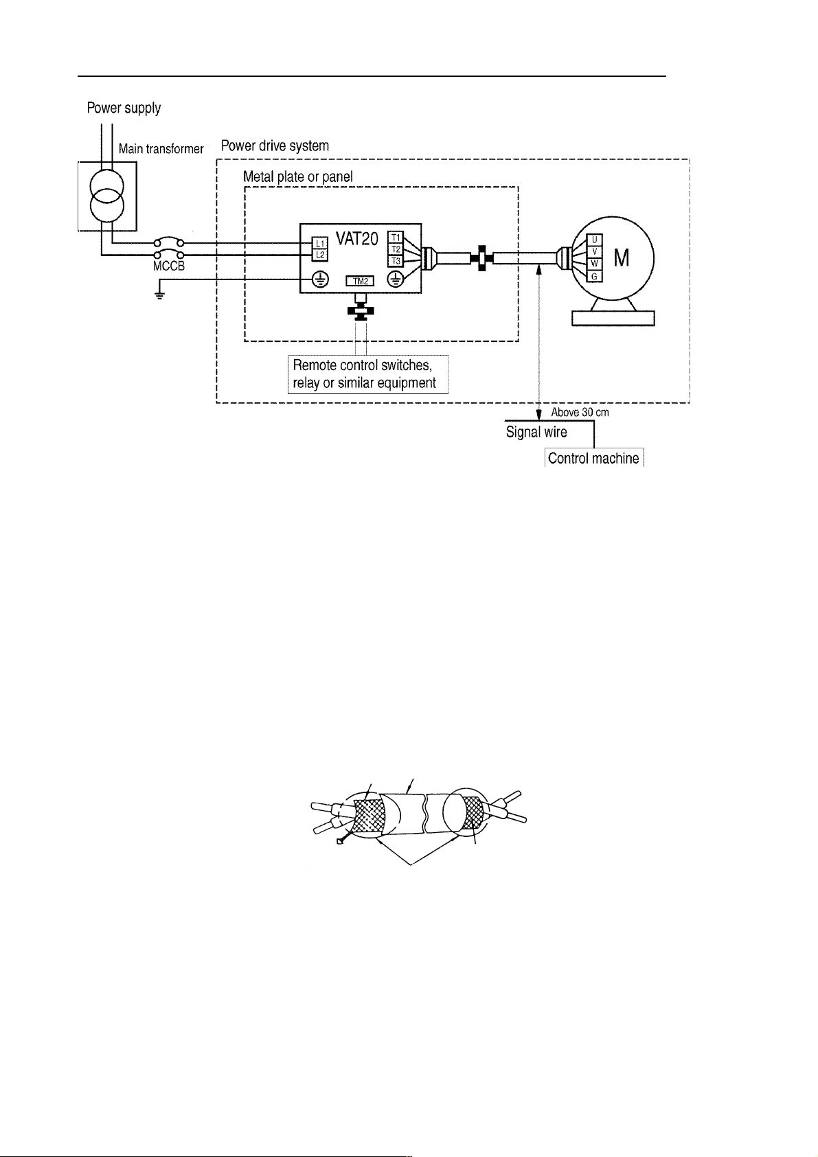
EMI connecting:
It is very important that the connections between the frequency inverter with the screened motor cable
and the EMI filter during the EMI tests are as following.
l Use a metal grounding plate and place the frequency inverter and the EMI filter on the plate.
l Use a screened motor cable with 4 connectors ( U,V,W,& Earth ), don’t use the shielding as
safety earth ( shield is high frequency earth )
l Remove painting around the two metal coupling nut holes. So that the metal coupling nuts (and
the shielding) make contact with the frequency inverter and the motor.
l Don't solder a conductor to the shielding (pig tail)
l Use a metal clamp to connect the shielding from the motor cable with the metal grounding plate.
Now there is a perfect high frequency earth connection between frequency inverter . grounding
plate and EMI filter.
l Keep the distance between frequency inverter and EMI filter as short as possible ( < 30cm )
otherwise use screened cable with a metal coupling nut and a metal clamp addle to connect th e
shielded cable to the frequency inverter and metal grounding plate.
l The only earth connection between the LISN and the test plate should be via the EMI filter.
l Use a motor which equals the power rating or below of the inverter rating.
l Install a noise filter for inverter onto the output side of the primary circuitry can suppress conduc-
ting noise (for residential environment only). To reduce radio active noise, use a shielded wire
between motor and drive, this wiring should be away from control wiring for more than 30 cm.
Class B, Residential Environment
14
Page 15
Class A, Industrial Environment (only for drives with built-in EMC class A filter, U20----S)
Power part
l When the distance between the inverter and motor is longer than 100m, connection wire
should be carefully chosen to reduce the wiring resistance below 3% and the voltage drop (V)
-3
= √ 3 x Wire resistance (Ω/km) x wire length (m) x current x 10
(B) Control circuitry wiring must be separated and away from the primary circuitry control line and
other high-voltage or large-current power lines to avoid noise interference.
l To reduce the noise interference and avoid mistake operation, shielded twisted pair cable must
be used to wire the control circuitry. Please refer to following diagram. Connect the shielding
wire onto the grounding terminal.
Wiring distance must be under 50m.
To Inverter terminal
Connect to system grounding terminal
Shielding
Glove
Wrapped with
insulating tape
To control machine
Do not connect the shielding
wire at this end
(C) The grounding terminal of the inverter must be correctly grounded in compliance with 200V class
type three grounding.
l Grounding wire should be wired in accordance to electrical equipment (AWG) with the length
of the grounding wire as short as possible.
l The grounding wire of the inverter must not be grounded together with other large current
loading (such as soldering machine or large power motor). They should be grounded
separately.
15
Page 16

l Grounding circuitry must not be formed when grounding several inverters together.
Good Good Not good
(D) Wire specification Choose appropriate wire with correct diameter for primary power circuitry and
control circuitry in accordance with electricity regulations.
(E) Upon completion, check out to reassure the w iring correctness, broken w ires, and secure termina l
screws.
Wiring Diagram
Braking Resistor
(option)
Power Supply Input
Single phase drives:
L1-L2 or L1-L3
Three phase drives:
L1-L2-L3
Multifunction
input
2.5-10k
Ω
Multifunction
output
For fac t ory
test only
Grounding
Terminations to Inverter must be made with either UL listed field wiring lug kits or UL listed crimp type
ring terminals
Note: only for U20-N1K5/N2K2 and U20-X0K7/X1K5/X2K2
l Other connections(external 24V supply)
16
Page 17

VAT20 series inverter terminal descriptions
Primary circuitry terminal black (TM1) descriptions
Terminal symbol Function description
L1 (R)
L2 (S)
L3/N (T)
Primary power source input to drive
Single phase (1ph) drives: L1, L2 or L, N
Three phase (3ph) drives: L1, L2, L3
P
R
T1 (U)
T2 (V)
T3 (W)
External braking resistor terminals
(Only for U20-N1K5/N2K2 and U20-X0K7/X1K5/X2K2)
Inverter output to motor
* Tightening torque for TM1 is 0.98, or 12 LBS-IN (U20-N0K2/N0K4/N0K7).
* Tightening torque for TM1 is 1.3 or 16 LBS-IN (U20-N1K5/N2K2 and U20-X0K7/X1K5/X2K2)
* Wire voltage rating must be a minimum of 300V (200V series)/600V (400V series)
VAT20 control circuitry terminal block ( TM2 ) description
Terminal symbol
TRIP
1
RELAY
2
3 FWD
4 REV
Fault relay output terminal
Connection point rated capacity 250VAC/1A ( 30VDC / 1A )
Operation control terminals (refer to Fn_03)
Terminal function description
5 + 12V Common point of terminal 3 / 4 / 6 / 7
6 SP1
7 RESET
8 +10V Power terminal of potentiometer ( Pin 3 )
9 Analog input point Analog frequency signal input terminal ( Pin 2 of
0V
10
(FM -)
11 FM+ Analog output positive
Multifunction input terminals (refer to Fn_19)
potentiometer or positive terminal of 0~10V / 4~20mA /
0~20mA)
Analog common point Analog signal common point ( Pin 1 of po tentiometer or
negative terminal of 0~10V / 4~20mA / 0~20mA )
Analog frequency signal output terminal
connection point
Output terminal signal is 0 ~ 10VDC/Fn6
* Tightening torque for TM2 is 0.4 Nm or 5.03 LBS-IN.
* Wire voltage rating must be a minimum of 300V for 200V inverters and minimum 600V
for 400V inverters
* Control wiring should not run in the same conduit or race way with power or motor wiring
* Single Input and Output Terminals (TM2) Ratings are all Class 2
17
Page 18

SW1 function description
SWITCH 1 External signal type
0~20mA analog signal ( When Fn11 set to 1 )
4~20mA analog signal ( When Fn11 set to 2 )
0~10 VDC analog signal ( When Fn11 set to 1 )
2.5. Dimension s and terminal block layout
Frame 1: U20N0K2, U20N0K4, U20N0K7
Terre
Grounding
Grounding (see note)
Plaquette de terre (voir note)
Type
U20N0K2
U20N0K4
U20N0K7
NOTE
For safety reason, we strongly
recommend users to remove the M4
‘green’ grounding screw, then screw
the enclosed ‘metal frame grounding
terminal’ on the same location to make
a grounding bar to ensure good earth
protection.
Length
D E F G
8.2 118 61 72
18
Page 19

Frame 2: U20N1K5, U20N2K2, U20X0K7, U20X1K5, U20X2K2
Grounding
M4 terre
Plaquette de terre (voir note)
Grounding (see note)
NOTE
For safety reason, we strongly
recommend users to remove the M4
‘green’ grounding screw, then screw
the enclosed ‘metal frame grounding
terminal’ on the same location to make
a grounding bar to ensure good earth
protection.
19
Page 20

Dimensions and Installation of class B filter (U20AF0K7)
Inverter with class B filter (U20AF0K7) mounted.
Inverter with class B filter (U20AF0K7)
and DIN rail (U20AR0K7) mounted.
20
Page 21

Mounting screw operation diagram
DIN rail (U20AR0K7) operation diagram
Step 1
Aim and insert the
4 retention ribs of
U20AR0K7 at the
4 holes in rear
panel of VAT20 .
Step 2
Push the
U20AR0K7
forward until the
middle rib grips
firmly with real
panel
Inserting hole
Retention rib
middl e ri b
Step 1
Use small screw
driver inserting
the middle rib of
U20AR0K7 and
press the screw
driver in order to
strip U20AR0K7
from VAT20.
21
Page 22

DIN rail installation
Mounting clamp and 35 mm width rail must be used to install VAT20 on the rail.
Install VAT20 Dismounting VAT20
Mounting plate
First place the groove on the back of
module on the upper edge of din rail ,
and then push the module down to lock
up position. Finally press the mounting
plate upward into module.
Mount
2
Screwdriver
1
1 Pull the mounting plate downward.
2 Rotate the T-verter module to dismount it.
Pull mounting plate
Mounting clamp
(1) Mounting clamp must be used to fasten VAT20
22
(1)
DIN Rail
Page 23

Chapter 3. Software Index
3.1. Control Panel Instructions
POWER LED
▲
▼
DATA
ENT
RUN
STOP
STOP
STOPSTOP
CAUTION
Do not operate keypad by screwdriver or other sharp-ended tool to avoid damaging keypad.
DSP
FUN
Brief keypad operation flowchart
(2)
DSP
FUN
(FREQ) (1)
F ××
(FREQ)
(READ)
DATA
ENT
F ××
×××
DSP
FUN
(1) Displayed setting frequency when stopped. Display output frequency when running.
(2) The setting frequency can be modified either when stopped or when running.
AFTER
0.5 SEC
END
23
(WRITE)
DATA
ENT
×××
Page 24

3.2. List of parameters
Function FN_ Function Description
0 Fact ory Adj ustment 0
Accel e ra te /
Decelerate Time
Operation mode
Motor direction 4 0: Forward 1: Reverse 1 0 ~ 1 0 (1)
V/F Pattern 5 V/F pattern setting 1 1 ~ 6 1/4 (2)
Frequency
upper/lower limit
SPI frequency
JOG frequency
Operation control 10 0:keypad 1: external terminal 1 0 ~ 1 0
Frequency control
Carrier frequency
Torque compensation 13 Torque compensation gain 0.1% 0.0 ~ 10.0% 0.0% (1)
Stop method 14 0:decelerate stop, 1:free run stop 1 0 ~ 1 0
DC braking setting
Electronic thermal
Multifunction input
connection point
1 Accelerate time 0.1 sec 0.1 ~ 999 S 5.0 (1)(3)
2 Decelerate time 0.1 sec 0.1 ~ 999 S 5.0 (1)(3)
3 0: Forward / Stop, Reverse / Stop
1:Run/Stop, Forward / Reverse
6 Frequency upper limit 0.1Hz 1.0 ~ 120Hz
7 Frequency lower limit 0.1Hz 0.0 ~ 120Hz
8 SP1 frequency 0.1Hz 1.0 ~ 120Hz
9 JOG frequency 0.1Hz 1.0 ~ 120Hz
11 0:keypad
1:external terminal(0~10v/0~20mA )
2: external terminal ( 4~20mA )
12 Carrier Frequency setting 1 1 ~ 5
15 DC braking time 0.1S 0.0 ~ 25.5S 0.5S
16 DC braking injection frequency 0.1Hz 1 ~ 10Hz 1.5Hz
17 DC braking level 0.1% 0.0 ~ 20.0% 8.0%
18 Protection on motor rated current 1% 50 ~ 100%
19 Multifunction input terminal 1 function 2
20 Multifunction input terminal 2 function
Unit Range Factory
setting
1 0 ~ 1 0
50/60Hz (2)(3)
1.0 ~ 200Hz
0.0Hz (3)
0.0 ~ 200Hz
10Hz (3)
1.0 ~ 200Hz
6Hz (4)
1.0 ~ 200Hz
1 0 ~ 2 0
5 (4)
1 ~ 10
100% (4)
(0-200)
1: Jog 2: Sp1
3: Emergency stop
4: External Base Block
5: Reset 6: Sp2
5 (4)
Note
(4)
(4)
(4)
21 Multifunction output terminal 1: Operating
Multi-function output
Reverse instructio n
Momentary power loss 23 0: enabled 1: disabled 1 0 ~ 1 0
Auto restart 24 Number of Auto-restart times 1 0 ~ 5 0
Factory setting
SP2 frequency 26 Frequency SP2 0.1Hz 1.0 ~ 200Hz 20 (4)
SP2 frequency 26 Frequency SP3 0.1Hz 1.0 ~ 200Hz 30 (4)
Direct start 28 0: enable 1: disable 1 0 ~ 1 1 (5)
Software version 29 CPU program version
Fault trace 30 Last 3 malfunction memory
(1) Indicate this parameter can be adjusted during running mode
(2) Please refer to Fn_25
(3) If the setting range is above 100, the setting unit becomes 1.
(4) Only for drives with CPU version from 1.9 (check function F_29)
(5) Only for drives with CPU version from 2.1 (check function F_29)
22 0: REV run enabled
1: REV run disabled
25 010: Constants initialization to 50Hz system
020: Constants initialization to 60Hz system
24
2: Frequency reached
3: Fault
1 0 ~ 1 0
3
(2)
Page 25

3.3. Parameter function description
Fn_00 Factory adjustment parameter. Do not change.
Fn_01 : Accelerate time = 0.1 up to 999 sec
Fn_02 : Decelerate time = 0.1 up to 999 sec
1. Accelerate/decelerate time calculation formula:
Setting Frequency Accelerate time = Fn_01 x
60 Hz
Setting Frequency Decelerate time = Fn_02 x
60Hz
Fn_03 : Operation mode selection =
0 : Forward / Stop , Reverse / Stop
1 : Run / Stop , Forward / Reverse
Note 1: Fn_03 take effect only when Fn_10 = 1 (external operation control)
Fn_03 = 0
control method
3 FWD /Stop
4 REV /Stop
5 COM
TM2 PIN3
TM2 PIN4
Fn_03=0
Output
Fn_03=1
Output
Forward
Forward
Reverse
Fn_03 = 1
control method
Reverse
(1)
3 Run / Stop
4
FWD/ REV
5 COM
(1)
(1) Reverse command is ignored when Fn_22 = 1
25
Page 26

Fn_04 : Motor rotation direction setting = 0 : forward
1 : reverse
Although there is no Forward/Reverse push button on the digital control panel, it is possible to
adjust forward/reverse function by changing Fn_04 setting.
Note:
When Fn_22 =1: Reverse disabled, the Fn_04 can not be set to 1. Then keypad indication would
display “LOC”.
Fn_05 : V/F pattern setting = 1 up to 6
Adjust Fn_05 = 1-6 to select one of six fixed V/F pattern. (refer to following tables)
Specification 50 Hz system
Application General application High starting torque Decreasing torque
Fn_5 1 2 3
V (%)
V (%)
V (%)
V/F pattern
100
B
C
1 2.5 50 120
Hz
100
B
C
1 2.5 50 120
Hz
100
B
C
1 25 50 120
Hz
Specification 60Hz system
Application General application High starting torque Decreasing torque
Fn_5 4 5 6
V/F pattern
V (%)
100
B
1 3.0 60 120
Hz
100
B
C
1 3.0 60 120
V (%) V (%)
100
B
C
Hz
1 30 60 120
Hz
Fn_5 B C
¼ 10% 8%
2/5 15% 10.5%
3/6 25% 7.7%
26
Page 27

Fn_06 : frequency upper limit = 1 up to 120Hz or 200Hz
Fn_07 : frequency lower limit = 0 up to 120Hz or 200Hz
(*) Only for with CPU version from 1.9 (check function F_29)
Internal
frequency
signal
(NOTE)
Frequency setting signal
Fn_06 (freq. Upper limit)
Fn_07 (freq. Lower limit)
(*)
(*)
Note:
If Fn_07 = 0 Hz, and the frequency instruction is equal to 0Hz, the inverter will
stop at 0 speed.
If Fn_07 > 0 Hz, and the frequency instruction ≦ Fn_07, the inverter will
output according to Fn_07 setting.
(*)
(*)
Fn_08 : sp1 frequency = 1 up to 120Hz or 200Hz
Fn_09 : jog frequency = 1 up to 10Hz or 200Hz
(*)Only for with CPU version from 1.9 (check function F_29)
1. When Fn_19 or Fn_20 = 2 and multifunction input terminal is ON, the inverter operate at
sp1 frequency (Fn_08)
2. When Fn_19 or Fn_20 = 1 and multifunction input terminal is ON, the inverter operate at
jog frequency (Fn_09)
3. The priority of reading frequency setting is Jog
signal
> Sp1 > Keypad setting or external frequency
27
Page 28

Fn_10 : Operation Control
= 0 : Keypad
= 1 : External terminal TM2
Note:
When Fn_10=1 (external operation control), emergency stop on the keypad is enabled.
When Fn_10=1, please refer to t he descriptions of F_23 /24, in o rder to avoid the da mage
to the human and the machine.
F_10=1
or =0
F_09=10Hz
F_19=1
F_08=30Hz
F_20=2
Hz
OFF
Time
ON OFF
ON OFF
OFF ON
ON
OFF
OFF
Fn_11 : Frequency control
= 0 : Frequency instruction is setup by keypad
= 1 : Frequency instruction is setup by VR or analog signal
on TM2 ( 0 up to 10V / 0-20mA )
= 2 : Frequency instruction is setup by VR or analog signal
on TM2 ( 4-20mA )
Note 1:
When Jog frequency or Sp1 freq uency is switched on,
the frequency is setup by Sp1 speed, the
buttons on the keypad is disabled. Original setting
will be restored after Sp1 connection is OFF.
Note 2:
During the contact closure of the jog function,
the keypad control remains in a sleep state until the
jog contact connection is re-opened.
▲▼
28
Page 29

Fn_12 : carrier frequency = 1 up to 5 or up to 10
(*)
(*) Only for drives with CPU version from 1.9 (check function F_29)
F_12 Carrier frequency F_12 Carrier frequency F_12 Carrier frequency
1 4 kHz 5 8 kHz 9 15 kHz
2 5 kHz 6 10 kHz
3 6 kHz 7 12 kHz
4 7.2 kHz 8 14.4 kHz
(1)
10 16 kHz
(1)
(1)
(1)
(1)
(1) If F_12 = 7 up to 10, the inverter must operate with low load.
Although an IGBT TYPE inverter can pr ovide a low audib le noise level dur ing its operation, it i s possible
that the switching of the high carrier frequency may interfere with external electronic components (or
other controllers) or even cause vibration in the motor. Adjusting the carrier
frequency can usually correct this problem.
Fn_13: Torque compensation gain = 0 up to 10 %
To enhance Inverter output torque patterns according to the B, C voltage points on the V/F patter n (refer
to F_05 description) and the (F_13) for this feature.
Note : When Fn_13 = 0, the torque boost function is disabled.
29
Page 30

Fn_14: Stopping method = 0 : decelerate stop
1 : free run stop
Fn_15: DC braking time = 0 up to 25.5 sec
Fn_16: DC braking starting frequency = 1 up to 10Hz
Fn_17: DC braking level = 0 up to 20%
If Fn_14 = 0
When the inverter receive the stop instruction, it decelerate to the frequency setup by Fn_16 and
then output voltage level setup in the Fn_17; after the time duration setup in Fn_15, the inverter
turn into complete stop.
Run command
Output frequency
DC braking frequency
If Fn_14 = 1
The inverter stop output immediately after receiving stop instruction. The motor get into free running
state to completely stop.
Fn_18: Motor rated current = 50 up to 100 % or 0 up to 200%
(*) Only for drives with CPU version from 1.9 (check fnction F_29)
Deceleration time
DC braking time
(*)
1. Function of the electronic thermal protecting motor
(1) Motor rated current = Inverter rated current x Fn_18
Fn_18 = Motor rated current / inverter rated current
(2) When the load is within 100% of the motor rated current, the operation continues. When the
load reaches 150% of the motor rated current the operation may continues for only 1 minute.
(refer to curve (1) in figures 3)
(3) After protecting the motor with the electronic thermal switch activated, the inverter is cut off
immediately. The OLI light w ill flash. To resume oper ation, push the RESET button or activate
an external reset connection wired to terminal 2.
(4) When the motor is operating at low speeds, the heat dissipation efficiency is lower. The
electronic thermal activation level is also reduced. (to change from curve (1) to curve (2) in
Figure 3. Choose the appropriate Fn_05 setting according to the applied motor to reach the
desired performance.
30
Page 31

2. Function of the electronic thermal protecting inverter
(1) When the load is within 103% of the inverters rated current, the operation continues.
When the load reaches 150% of rated current of the inverter, the operation will continue
for 1 minute. ( Refer to curve (1) of figure 3)
(2) After the activation of the electronic thermal switch, the inverter is shut off immediately.
The OL2 light will flash. To resume th e operation, push RESET button or activate an external
reset contact on terminal 2.
Derating
Fn_05 = 1,2,3
50 Hz standard motor
%
100
90
60
Derating %
Decay
Fn_05 = 4,5,6
60 Hz standard motor
100
90
60
1.0
20 50 (Fig. 1)
20 60 (Fig. 2)
(Fig. 3) 100 150 Percentage of
Current
Fn_19: Multifunction input terminal 1 function = 1 up to 5 or 6
Fn_20: Multifunction input terminal 2 function = 1 up to 5 or 6
(*) Only for drives with CPU version from 1.9 (check fnction F_29)
1. Fn_19, Fn_20 =1 : JOG (refer to F_09)
2. Fn_19, Fn_20 = 2 or 6 multispeed control
Multi-speed control (only for drives with CPU version from 1.9)
F_19 = 2 and F_20 = 6
TM2 SP1 Terminal TM2 RESET Terminal Output frequency
ON OFF (F_08)
OFF ON (F_26)
ON ON (F_27)
(*)
(*)
F_19 = 6 and F_20 = 2
TM2 SP1 Terminal TM2 RESET Terminal Output frequency
ON OFF (F_26)
OFF ON (F_08)
ON ON SP3 (F_27)
31
Page 32

3. Fn_19, Fn_20 =3: External emergency stop signal
When the external emergency stop signal is activated, the inverter proceeds to decelerate and
stop, (ignoring the setting of Fn_14). The inverters E.S. light will flash after stopping. After the
emergency stop signal is deactivated, turn the RUN switch OFF and then ON again to cycle it.
(Fn_10 =1) Or, push the RUN key (Fn_10=0). The inverter w ill then r esume operation and r estart.
If the emergency stop signal is r emov ed before the inver ter stop s, the inver t er w ill sti ll execute the
emergency stop.
4. Fn_19, Fn_20 =4: External Base Block (immediate shut off)
When the external base block signal is activated, the inverter output will be immediately shut off
(ignoring setting in Fn_14) and flash b.b. After the base block signal deactivated, turn the RUN
switch OFF and then ON again (Fn_10 = 1) or push the RUN key (Fn_10=0), the inverter will
restart from the starting frequency.
5. Fn_19, Fn_20 = 5: Reset when inverter fault.
Fn_21: Multi-function output terminal = 1 up to 3
1.
Fn_21 = 1: Run mode signal
2. Fn_22 = 2: Frequency agreed signal
3. Fn_21 = 3: Fault signal
Terminal 1 and 2 of TM2 are activated at CPF, OL1, OL2, OCS, OCA, OCC, Ocd , Ocb , OVC , LVC ,
OHC.
32
Page 33

Fn_22:Reverse instruction = 0 : REV command enabled
= 1 : REV command disabled
Note:
When Fn_04 is set to 1 (reverse), Fn_22 can not be set to 1, indication displays “LOC”.
Fn_04 must be change to 0 before setting Fn_22 to 1.
Fn_23: Restart after momentary power loss
= 0 : restart enabled
= 1 : restart disabled
1. When the AC power supply is temporary below low voltage protection levels because of power
company issues or encountering large current loading in the same power supply system, the
inverter will stop its output immediate ly. If the powe r source resumes within 2 seconds, the inver ter
can restart by using its speed search program.
2. When F_23=0:
(1) If the momentary power loss is less than 2 seconds, the inverter resume operation
automatically via speed search at 0.5 seconds after power up. The number of auto-restart
times is not limited by F_24.
(2) If the momentary power loss is long, the operation of the inverter is based on the setup of F_10
and the condition of external switch.
(3) If the time of momentary loss is between the above two, whether the inverter will auto-restart
depends on F_24:
F_24=0: auto-restart disabled.
F_24=1~5: auto-restart enabled 1~5 times.
3. When F_23=1,
(1) Power up after momentary power loss, the inverter will not start. Even under F_24>0.
(2) If the momentary power loss is long, the inverter must be restart manually. The operation of
the inverter is based on the setup of F_10 and the condition of external switch.
4. When restart the inverter, the operation of the inverter is based on the setup of F_10 and the
condition of external switches (FWD/REV button).
(1) When F_10=0, the inverter will not start after restart.
(2) When F_10=1 and the external switch (FW D/REV button) is OFF, the inverter will not start
after restart.
(3) When F_10=1 and the external switch (FWD/REV button) is ON, the inverter will start
automatically after restart. Attention: Base on safety reason, please turn off the external
switch (FWD/REV button) after power loss to avoid possible damage to the machine and
the human body after sudden regeneration of power.
33
Page 34

Fn_24: Number of Auto-restart times = 0 up to 5
1. When Fn_24 = 0, the inverter will not try to restart.
(Except for momentary power loss, please refer to F_23 for details)
2. When Fn_24 > 0 , the inverter will resume operation via SPEED SEARCH at approximately
0.5 second after a function trip. After that, the inverter will accelerate or decelerate to current
frequency setting.
(Except for momentary power loss, please refer to F_23 for details)
3. When the inverter is set to deceleration or DC breaking, the transient restart procedure is not
performed.
4. When either of following situation happen, the transient restart count will be reset:
(1) No additional malfunction (in operation or stop) occurs within 10 minutes.
(2) Press RESET button or external terminal RESET is ON.
Fn_25 : Factory settings function
= 010 : Constants initialisation to 50Hz system
= 020 : Constants initialisation to 60Hz system
1. When Fn_25 is set to 010, all parameters are restored to factory settings. The settings of
Fn_05 =1 and Fn_06 = 50. Fn_25 is restored back to 000 after the reset process complete
(50Hz operation).
2. When Fn_25 is set to 020, all parameters are restored t o factory settings. The settings of
Fn_05 =4 and Fn_06 = 60. Fn_25 is restored back to 000 after the reset process complete
(60Hz operation).
Fn_26: SP2 (1 up to 200Hz), multi-speed 2
(Refer to Fn_19, Fn_20)
Fn_27: SP3 (1 up to 200Hz), multi-speed 3
(Refer to Fn_19, Fn_20)
34
Page 35

F_28: Direct start
= 0 : Direct start enable when remote Run command on
= 1 : Direct start disable when remote Run command
on drives with CPU version from 2.1
(check function F_29)
When F_28 = 1 and control mode is remote control (F_10 = 1), the inverter can not start if RUN switch is
ON when power is engaged, must be turned the RUN switch OFF and turned ON again, then inverter
can start.
Fn_29: software (program) version
Fn_30: Fault trace
1. Fault trace : i ndicate the sequence of the occurrence of malfunctions by the location of decimal
point. x.xx indicate a recently happened malfunction. xx.x indicate the last malfunction that
happened. xxx. indicated the earliest malfunction in the record.
2. After entering the Fn_30 function, the x.xx record will be displayed first. After that, press button
can read out xx.x xxx. x.xx ,,, consecutively.
3. After entering Fn_30 function, if the RESET button is pressed, all three malfunction record will be
cleared. Indication display
4. W hen the content of malfunction memory indicate O.CC, indicate the latest malfunction code is
OC-C and so on.
-.--, --.-, and ---.
35
Page 36

3.4. Malfunction indication and countermeasur e
3.4.1. Manual reset inoperative faults
INDICATION CONTENT POSSIBLE CAUSE COUNTERMEASURE
CPF
EPR
OV
LV
OH
Program error
EEPROM error
Voltage too
high while not
operating
Voltage too low
while not
operating
Inv erter over
heat while not
operating
Outside noise interference Place a RC surge absorber in
parallel with the noise
generating magnetic contact
EEPROM defective
1. Power source voltage
too high.
2. Detection circ uitry
defective
1. Power source voltage
too low.
2. Detection circ uitry
defective.
1. Detection circuit defective.
2. Environment over-heat or
poor ventilation
Replace EEPROM
1. Examining the power supply
2. Return the inverter for repair
1. Examining the power supply
2. Return the inverter for repair
1. Return the inverter for repair
2. Improve ventilation
3.4.2. Manual reset operative faults (Auto-Reset inoperative)
INDICATION CONTENT POSSIBLE CAUSE COUNTERMEASURE
OC
OL1
OL2
Over-current at
stop condition
Motor over-load
Inverter over-load
Detection circuit
malfunction
1. Loading too large
2. Improper V/F model setting
3. Improper Fn_18 setting
1. Loading too large
2. Improper V/F model setting
Return the inverter for repair
1. Increase capacity of motor
2. Adjust to use a proper V/F curve
setting
3. Adjust Fn_18 according to
instruction
1. Increase capacity of inverter
2. Adjust to use a proper V/F curve
setting
36
Page 37

3.4.3. Manual Reset and Auto-Reset Operative faults
INDICATION CONTENT POSSIBLE CAUSE COUNTERMEASURE
Transient
OCS
OCA
OCC
OCd
OCb
OVC
LVC
OHC
over-current
starting machine
Over-current at
acceleration
Over-current at
steady speed
Over-current at
deceleration
Over-current at
breaking
Over-voltage at
operation/deceler
ation
Insufficient
voltage level at
operation
Heat -sin k over
heated at
operation
1. Motor coil short-circuit with
external casing
2. Motor connection wire
short-circuit with grounding
3. Transistor module
damaged
1. Acceleration time setting
too short
2. Improper V/F feature
selection
3. Applied motor capacity
exceeds inverter capacity
1. Transient alteration of the
loading
2. Transient alteration of the
power supply
Deceleration setting too short
DC Breaking frequency,
breaking voltage, or breaking
time setting too long
1. Deceleration time setting
too short or inertial
loading too large
2. Power supply voltage
variation too large
1. Power supply voltage too
low
2. Power supply voltage
variation too large
1. Loading too heavy
2. Ambient temperature too
high or poor ventilation
37
1. Examining motor
2. Examining wiring
3. Replace transistor module
1. Adjust acceleration time to
longer setting
2. Adjust to a proper V/F curve
3. Replace and install another
inverter with appropriate
capacity
1. Examining the loading
configuration
2. Install inductor on the power
supply input side
Adjust to use a longer
accel e ration time
Adjust to reduce settings of
Fn_15, Fn_16, or Fn_17
1. Adjust to use a longer
deceleration time
2. Install a inductor on the power
supply input side
3. Increase the capacity of
inverter
1. Improve power source quality
2. Adjust to use a longer
accel e ration time
3. Increase capacity of inverter
4. Install a reactor on the power
supply input side
1. Examining the loading
2. Increase capacity of inverter
3. Improve ventilation
Page 38

3.4.4. Other indications
INDICATION CONTENT DESCRIPTION
SP0
SP2
E.S.
b.b.
Zero Speed
Stopping
Keypad
emergency stop
External
emergency stop
External BASE
BLOCK
When Fn_11 = 0, Fn_7= 0 and frequency setting < 1 Hz
When Fn_11 = 1, Fn_7<(Fn_6/100), and frequency setting
<(Fn_6/100)
The inverter setup to external operation ( Fn_10=1). If the S TOP
key in the keypad is pressed at the middle of operation, the
inverter stop according the setting in Fn_14 and flash SP2 after
stop. The RUN switch must be turn ed OFF than ON to restart
the machine.
When the external emergency stop signal is activated through
the multi-function input terminal, the inverter decelerate and
stop. Inverter flash E.S. after stop. (Refer to instruction for
Fn_19 for detail).
When the external BASE BLOCK s ignal is ac tivated through the
multifunction terminal, the inverter stop output immediately and
flash b.b. for indication. (refer to instruction for Fn_19 for detail)
3.4.5. Keypad Operation Error Indications
INDICATION CONTENT POSSIBLE CAUSE COUNTERMEASURE
LOC
Er1
Er2
Motor direction
locked
Keypad operation
error
Parameter setting
error
1. Attempt to reverse
direction when F n_22 = 1
2. Attempt to set Fn_22 to 1
when Fn_04 = 1
1. Press ▲ or ▼ keys when
Fn_11=1 or under sp1
operation
2. Attempt to modify Fn_29
3. Attempt to modify
parameter that is not
allowed to be modified
during operation (refer to
parameter list)
1. Fn_6
≤ Fn_7
1. Adjust Fn_22 to 0
2. Adjust Fn_04 to 0
1. Use ▲ or ▼ keys to adjust
frequency setting only after
Fn_11=0
2. Do not modify Fn_29
3. Mod ify in stop mode
1. Fn_6 > Fn_7
38
Page 39

3.5. General Troubleshooting Method
ABNORMALITY CHECK POINT COUNTERMEASURE
Motor
inoperative
Is power source voltage delivered into L1,
l Check if the power source switched on.
L2 terminal (is the charging indicator
illuminated)?
l Turn power source OFF and then ON
again.
l Reconfirm the power voltage level.
l Check to see if the mounting screw
secured.
Is there voltage output from output
terminal T1, T2 and T3?
l Turn power source OFF and then ON
again.
If the loading too heavy to block motor? l Reduce load to start motor.
Is there any abnormal condition of the
inverter?
l Refer to malfunction handling
instructions to examine and correct
wiring.
Is the forward or reverse instruction
loaded?
Is the analog frequency setting loaded?
l Check to see if wiring for analog
frequency input signal is correct?
Motor operate in
opposite direction
Motor operation
speed fixed
Motor operation
at speed too
high or too low
Abnormal speed
variation at
operation
If the operation mode setting correct?
l Check if the frequency input setting
voltage is correct?
Is wiring on the output terminals T1, T2
l Operate by digital?
and T3 correct?
Is the wiring for the forward and reverse
signals correct?
Is the wiring for analog frequency input
l Wiring should be in accordance with the
U, V, W terminals of motor.
l Examining the wiring and correct it.
correct?
Is the operation mode setting correct? l Examining the wiring and correct it.
Is the loading too heavy?
l Operation panel operation mode setting
check.
Is the specification of motor (poles,
l Reduce loading
voltage) correct?
Is the gear ratio correct? l Reconfirm mo tor specification.
Is the highest output frequency setting
l Reconfirm gear ratio
correct?
Is the voltage on motor side reduced
l Reconfirm highest output frequency
extremely?
Is the loading too heavy? l Reduce loading variation
Is the loading variation too large? l Increase inverter and motor capacity
Is the input power source steady and
stable?
l Install AC reactor on the power supply
input side
39
Page 40

Simple VAT20 Troubleshooting Procedure
VAT20 INV M alfunction
Clearly defined
malfunction
YES
Sign of burn
or breakage
YES
Indication of
abnorm ality
Proceed exam ination
according to
malfunction indication
Control board, driver
board, carry out
visual inspection
Appearance
abnorm ality
NO
Switch power ON
NO
NO
NO
YES
Any sign of burnt
of breakage?
NO
Is the primary
circuitry DM norm al?
NORMAL
Is the primary
circu itr y I.G.B.T.
normal?
NORMAL
Replace defective board
YES
ABNORMAL
ABNORMAL
Exam ining component w ith
sign of burnt or breakage
Replace DM
Replac e I.G.B.T.
Malfunction
indication
(Continu ed o n 41 )
Any illu mina te d
indicator on the control
panel
YES
Any malfunction
indication
The malfunction
indication is?
Check to see the
three malfunction
record in Fn_30
Three malfunction
record in Fn_30
NO
NO
Is LED2 illumina te?
YES
Is the
DC in put vo lta g e
of control power
supply normal?
NORMAL
Is the control
pow er source + 5V
normal?
NORMAL
Replace control board,
digital controller.
Is replacin g
control board solve
the problem?
YES
NO
ABNORMAL
ABNORMAL
NO
Replace current surge
absorber
Examin ing termina ls
and wirings
Replace driver board
Inverter malfunction
Detail examination required.
40
Page 41

(Continued from 40)
Examining Inverter
parameters
Carry out parameter
initialization
Design at e operati on
control method
Frequency instruction
setting
Does the
controller displays
freque ncy setti ng ?
Is there
voltage ou t p u t on
UVW terminals?
Connect to motor and
procee d operati on
Is there
any abnormality
indication
NO
Is
output current of all
phases in balance
condition?
YES
The inverter is
normal now
NO
NO
YES
YES
NO
Replac e control b oard
Replac e control b oard
Is replacing
control board correct
the problem?
Yes, the pr oblem
has been correcte d
The inverter is out of order
Detail examination is required
No, The pr oblem
is not corrected
41
Page 42

Error handling of malfunction i ndication of OC.OL
When inverter display
malfunction indication
OC.OL.
Is the primary
circuit I.G.B.T.
normal?
NORMAL
Is the appearance
normal?
Switch ON power
supply
Is there any
malfunction indication
NO
Input op er ation
instruction
YES
Input frequ e n cy sett ing
ABNORMAL
YES
YES
Replace I.G.B.T.
Replace defective PCB
Is the current
detector normal?
Replace c ontrol board.
ABNORMAL
NORMAL
Replace detector.
Is the output frequency
displayed?
YES
Is there output
voltage on UVW
terminals?
Connect motor and
proceed wit h operation.
Is there an y malfunction
indication
NO
Is output
current of al l phases in
balance condition.
YES
The inverter is
normal now.
NO
NO
YES
YES
NO
Replace c ontrol board
Replace control board
Is replacing
control board correct this
Problem?
YES
Inverter is out of order.
Detail examination is required.
NO
42
Page 43

Error handling of malfunction i ndication of OV. LV
Inverter display OV.LV
Is there
any abnormal breakage
on appearance
Switch ON
power supply
Replace defective board
Is there any
malfunction indication
NO
Input operation
instruction
Input frequency
instruction
Is the output
frequency of controller
displayed
YES
Is there
output voltage on T1, T2,
and T3 terminals?
Connect motor. Is the
motor operating?
YES
NO
NO
YES
Replace control board
Replace control board
Replace control board
Is the problem
corrected by replacing
control board?
NO
Is there any malfunction
indication?
NO
Is output
current of all phases in
balance condition?.
YES
The inverter is
normal now
YES
NO
YES
The inverter is out of order
Detail examination is required
43
Page 44

(1) Motor inoperative
YES
Is the circui
t breaker (MCCB)
switched ON?
NO
Can you switch ON the
MCCB?
Is the
voltage betwee n
L1-L2 power i npu t termi n als
Is Power LED off ?
Is the operation
switch on the RUN
position?
normal?
Normal
(within +/- 10% of nominal value)
Can not
ABNORMAL
NO
NO
Wiring short-circ uit
• Power source
abnormality
• Poor wiring
VAT20 malfunction
Place the operation
switch to RUN
position.
YES
Is there
any output voltage on
motor T1-T2-T3?
Is the
T1-T2,T2-T3,T3-T1
output volt ag e i n bal ance
condition?
Motor over-load
D efec ti v e motor
Poor wiri ng
YES (When the motor is not connected, and the volt oge differences between
wires are within +/- 3% can be treated as in balance condition.)
NO
NO
VAT20 malfunction
VAT20 malfunction
44
Page 45

(2) Motor over-heat
Is
there over-loading
condition or the load current
exceeds rated
current?
NO
Operate at low
speed for a long time?
NO
Is the
voltage level between
T1-T2, T2-T3, and T3-T1
normal?
YES
Is there
anything that might
affect m o to r
cooling?
NO
Poor connection
between VAT20 and
motor
(3) Disturbing motor operation
YES
YES
NO
YES
YES
Reduce loading
Enlarge VAT20 and
Motor capacity
Select another motor
VAT20 malfunction
Remove obs tacle
affecting motor cooling
Correct the connection
During acceleration or
deceleration ?
NO
Is the
voltage level
between T1-T2, T2-T3, and
T3-T1 normal?
YES (The differences between different wires are within +-3%)
Is there any loading
variation condition?
NO
Is there
any excess vibration
at transmission parts
like gears?
YES
Is the
acceleration/
deceleration time setting
appropriate?
NO
YES
YES
Not
appropriate
Appropriate
Increase or decrease
acceleration /
deceleration time
Reduce load Increase
VAT20 and motor
capacity
VAT20 malfunction
Reduce loading
variation or install
fly wheel
Improve mechanical
system
NO
VAT20 malfunction
45
Page 46

Routine examination and periodical examination
Inverter requires routine and periodical examination and maintenance for a more stable and safer operation.
Refer to following table for required examination item for a more stable and safer operation.
Carry out examination after the “ Power LED ” indicator goes off for 5 minutes to prevent the maintenance
personnel injury caused by the remaining charges in the capacitor of inverter.
Maintenance
item
Installation site
environment
Inverter
Instal lation anf
grounding
Input power
source voltage
Inverter
external
terminal
mounting
screw
Internal wiring
of inverter
Heat-sink Is it accumulating dust or
PCB
component
Maintenance
description
Reconfirm environment
temper at ure and humidit y
Check and remove any
flammable material nearby
Is there a n y abnormal
vibration on the installation
site?
Is the grounding resistance
within ac c eptable r ange?
Is the voltage of the primary
circuitry norm al ?
Is the tighten parts secured?
Is there any sign of breakage
on the terminal panel?
Is there any obvious rusty
condition?
Is it deformed or skewed?
Is the insulation of wire
broken?
dirt?
Is it accumulating conductive
metal or oil stain?
Is there any over-heated or
burnt component?
Is there any abnormal
vibr ati on or n oi s e ?
Is it accumulating dust or
dirt?
Is it accumulating dust or
dirt?
Examine resistance between
each terminal
Is there any sign of strange
odor or lea k age?
Is there any sign of swelling
or bulging?
Examination
period
Routine 1 Year
°
°
°
°
Refer to insta llation
Visual inspection No foreign object
Visual and audio
°
Measure voltage by
°
°
°
°
°
°
°
°
°
Visual inspection No abnormality Clean up dust or dirt
°
°
°
Visual inspection
°
°
Capacitor
Examination
instructions and measure
with thermometer and
hygrometer
inspection
Measure resistance by
multi-meter
multi-meter
Visual inspection. Use
screwdriver to verify
screw tightness
Visual inspection
Visual inspection
Visual a nd au dio
inspection
Visual inspection No abnormality
Measure by multi-meter No short-circuit or
Visual inspection
method
Criterion
Countermeasure
Temperature: -10~40
OC Humidity: under 95 %
without condensing
No foreign object Tighten loose
200V class under 100
ohm
Voltage level conforming
specification
No abnormality
No abnormality
No abnormality
No abnormality
open-ci r cuit on th e
three-phase output
No abnormality
Improve installation
site environment
screw
Improve grounding
Improve input
power source
Tighten loos e screw
or return for repair
Replac e or r et ur n
for repair
Clean up or replace
PCB
Replace cooling fan Cooling fan
Clean up
Clean up Power
Replace power
compon ent or
inverter
Replac e capacit or
or inverter
46
Page 47

Chapter 4. Maintenance and Peripherals
4.1. Maintenance and Examination
Frequent examination and maintenance is not required for VAT20.
To maintain appropriate reliability for a long term of time, please proceed with following periodical
examination. Remember to turn off power supply and wait till the Power LED went off before
proceed. (Due to the large amount of remaining charges in the internal capacitors.)
(1) Clean out internal dust and dirt.
(2) Check out mounting screws on every terminal and parts. Tighten loose screws.
(3) Dielectric strength test
(a) Remov e all conducting wires between VAT20 and outside world. Power must be turned OFF.
(b) The dielectric strength test inside VAT20 should be carried out only for VAT20 major circuitry.
Use DC 500V: high resistance meter. Measured resistance should be higher than 100M ohm.
CAUTION: Do not perform dielectric strength test to the control circuit.
Input power source
DC-500V
high-resistance
L1 (R) T1 (U)
L2 (S) VAT20 T2 (V)
T3 (W)
Earth terminal
Connection for dielectric strength test
Motor
47
Page 48

4.2. Voltage Current Measurement
The voltage and current measurement on the primary and secondary side may be different for the
reason of the instrumentation and the high frequency wave. Refer to following diagram for
measurement:
L1 (L)
S
U
P
P
L
Y
V1
W1 A1
L2
W2 A2
L3 (N)
T1 (U)
T2 (V)
T3 (W)
V2
W4 A4
M
3ph
W5 A5
W3
V1
Moving iron type Voltmeter ( )
A3
V2 Rectifier type Voltmeter ( )
W1 Electrodynamometer type power meterto W6
A1 Moving iron type Ammeter ( )to A6
SPEED DRIVE
W6
A6
48
Page 49

4.3. Input AC Reactor Specification
(1)
VAT20 Model AC Reactor
U20N0K2 ACR3A7H0 37G00204 U20X0K7 ACR3A8H1 37G00201
U20N0K4 ACR8A2H5 37G00204 U20X1K5 ACR4A5H1 37G00402
U20N0K7 ACR12A2H5 37G00401 U20X2K2 ACR6A3H4 37G00402
1ph, U20N1K5
3ph, U20N1K5
1ph, U20N2K2
3ph, U20N2K2
ACR18A1H3
ACR6A2H5
ACR22A0H84
ACR9A1H3
(2)
AC Reactor
37G00801
37G01201
4.4. EMI Filter (class B) Specification
(3)
VAT20 Model AC Reactor
(1)
(2)
AC Reactor
Model Dimensions (mm) Current(A) VAT20 model
U20AF0K7 156X76X25 10A U20N0K2
U20N0K4
U20N0K7
U20AF2K2 170x221x38 U20N1K5
U20N2K2
(3)
U20AF2K2X 171x221x38 U20X0K7
U20X1K5
U20X2K2
4.5. DIN RAIL Specification
(1)
Model Dimensions VAT20 model
U20AR0K7 130x72x7.5 U20N0K2, U20N0K4, U20N0K7, U20N1K5,
U20N2K2
U20X0K7, U20X1K5, U20X2K2
4.6. Dynamic Braking r esistor Specification
VAT20 Model
U20N1K5 1.5 / 2
U20N2K2 2.2 / 3
U20X0K7 0. 75 / 1
U20X1K5 1.5 / 2
Motor kW / HP
Braking resistor
TLR100P200
TLR75P200
TLR750P200
TLR400P200
(1)
Braking resistor
DB2F22C
DB2F22C
DB0F754C
DB2F24C
(3)
U20X2K2 2.2 / 3
(1) All above are optional devices not included with the drive and sold separately.
(2) Optional device part numbers available in the European market
(3) Optional device part numbers available in the American market
TLR250P200
49
DB2F24C
 Loading...