

Page 1
GE Energy
Masoneilan* Products
ValVue* FF (Rev B)
Maintenance Manual
ValVue-FF is a software tool to
configure, calibrate, and operate
FOUNDATION Fieldbus
pneumatic control valve
positioners.
Page 2

Warranty
Items sold by GE Energy are warranted to be free from defects in materials and workmanship for a
period one (1) year from first use or eighteen (18) months from delivery provided said items are used
according to GE recommended usages. GE reserves the right to discontinue manufacture of any
product or change product materials, design or specifications without notice.
Software is warranted for ninety (90) days from delivery.
This instruction manual applies to the following instruments and approved software: FVP110
Positioner and ValVue
The FVP110 positioners are warranted for use only with interface software approved by GE Energy.
Consult factory locations for approved software listing.
About this Guide
This instruction manual applies to the following instruments and approved software:
❑ ValVueFF
The information in this manual is subject to change without prior notice.
The information contained in this manual, in whole or part, shall not be transcribed or copied without
GE Energy’s written permission.
In no case does this manual guarantee the merchantability of the positioner or the software or its
adaptability to a specific client needs.
*
software.
❑ with Firmware version 3
❑ with ValVueFF software 2.32 or greater
❑ with ValVue version 2.4 or greater
*
Digital
Copyright
GE Energy reserves the right to discontinue manufacture of any product or change product materials,
design or specifications without notice.
Please report any errors or questions about the information in this manual to your local supplier or
visit www.dressermasoneilan.com.
All software is the intellectual property of GE Energy.
The complete design and manufacture is the intellectual property of GE Energy.
*
Masoneilan
contained herein is believed to be accurate at the time of publication and is subject to change without
notice.
Copyright 2012 by GE Energy. All rights reserved.
P/N 720003262-888-0000 Rev B
, FVP*, SVI*, and ValVue
*
are registered trademarks of GE Energy. All information
Page 3

ValVueFF Software Interface to FVP
Contents
ValVueFF Software Interface to FVP Safety Information ...............................................................1
Safety Symbols ..........................................................................................................................1
Product Safety ...........................................................................................................................2
Introduction to ValVueFF and FVP ................................................................................................5
Overview ....................................................................................................................................5
ValVueFF Specifications............................................................................................................5
Installation of Hardware and Software ...........................................................................................7
Getting Started With ValVueFF..................................................................................................7
General Installation and Setup Procedure .................................................................................9
Wiring Requirements ...............................................................................................................10
Installing NIFB Software and Hardware...................................................................................10
NI-FBUS Software..............................................................................................................11
ValVueFF Administration .............................................................................................................17
Overview ..................................................................................................................................17
Administration ....................................................................................................................17
Installation Sequence.........................................................................................................17
Installing ValVueFF..................................................................................................................18
Launching the Application..................................................................................................18
Removing a Previous Version of ValVueFF.......................................................................18
Installing ValVueFF............................................................................................................21
Trial Period.........................................................................................................................26
Registration..............................................................................................................................27
Previous Versions ..............................................................................................................27
Registering ValVueFF Software.........................................................................................27
Setting User Accounts, System Administration, Passwords, and Privilege Levels............31
Using ValVueFF ...........................................................................................................................35
Overview ..................................................................................................................................35
Integrated Valve Interface (IVI) ..........................................................................................35
Menu Bar .................................................................................................................................36
Icon Toolbar .............................................................................................................................39
Tool Tips Feature...............................................................................................................39
Positioner Faceplate ................................................................................................................41
Active Faceplate................................................................................................................43
Companion Device Display Frame.....................................................................................44
Status Frame......................................................................................................................45
Selected Device Frame......................................................................................................45
Device Selection ................................................................................................................47
Using ValVueFF Menu Selections ...........................................................................................48
i
Page 4

GE Energy
ValVueFF Software Interface to FVP
Setup Menu..............................................................................................................................49
Setup Wizard .....................................................................................................................49
Configuration Services.......................................................................................................55
Calibration Services ...........................................................................................................56
Device Tag/Address...........................................................................................................57
View Menu ...............................................................................................................................58
View Trend.........................................................................................................................58
PID Controller ....................................................................................................................59
Device Operation State......................................................................................................61
Tools Menu ..............................................................................................................................62
Diagnostic Services ...........................................................................................................62
Query Device .....................................................................................................................63
Rescan Devices .................................................................................................................64
Help Menu................................................................................................................................ 65
About..................................................................................................................................65
Registration Info.................................................................................................................65
Offline Use of ValVueFF ..........................................................................................................66
Setup Wizard Procedure ..............................................................................................................67
Step 1: Welcome...................................................................................................................... 68
Step 2: Actuator Wizard...........................................................................................................69
Step 3: Tuning Wizard .............................................................................................................70
Step 4: Travel Calibration Wizard ............................................................................................72
Step 5: Position Control Limits Wizard.....................................................................................75
Step 6: Finish Setup Wizard ....................................................................................................77
Configuration Services .................................................................................................................79
Configuration............................................................................................................................ 79
General Page...........................................................................................................................80
Device Info .........................................................................................................................80
Block Tag Info ....................................................................................................................81
Others Installed..................................................................................................................81
Position Tab.............................................................................................................................82
Servo Parameters Frame...................................................................................................82
Position Limits Frame ........................................................................................................84
Limit Switch Threshold.......................................................................................................85
Fault Control ......................................................................................................................85
Actuator Page ..........................................................................................................................87
Diagnostic Parameters.......................................................................................................88
Model and Serial Number ..................................................................................................88
AO Block Tab...........................................................................................................................89
Limits..................................................................................................................................89
AO Block Options...............................................................................................................90
PID Block .................................................................................................................................92
PID Control and Status Option...........................................................................................94
ii
Page 5

Options.....................................................................................................................................96
Characterization Frame......................................................................................................96
Custom Characterization Dialog Box .................................................................................99
Pressure Frame ...............................................................................................................103
Others Frame ...................................................................................................................103
Calibration Services ...................................................................................................................105
Overview ................................................................................................................................105
Range Tab .............................................................................................................................105
Find Range Result ...........................................................................................................106
Auto Stop Limits...............................................................................................................106
Manual Stop Limits...........................................................................................................107
Open Stop Adjustment.....................................................................................................108
Tuning Tab.............................................................................................................................109
Auto Tune.........................................................................................................................111
Search Stops and Auto Tune In One Step.......................................................................112
Manual Parameter Adjustment.........................................................................................112
Travel Calibration Tab............................................................................................................112
Calibrating ........................................................................................................................113
Advanced Tab........................................................................................................................115
Advanced Servo Tuning Buttons......................................................................................115
Advanced Servo Tuning Parameters ...............................................................................116
Advanced (Double Acting) Tuning Parameters................................................................117
PID Block and Trending Services ..............................................................................................119
Overview ................................................................................................................................119
PID Status Frame ..................................................................................................................120
States and Modes ............................................................................................................120
Simulation Function..........................................................................................................121
Others - Tuning Parameters ..................................................................................................122
PID Output and Valve Position ..............................................................................................123
Trending Overview.................................................................................................................123
Zooming ...........................................................................................................................124
Customizing the Trend.....................................................................................................124
Viewing Valve Dynamic Responses.................................................................................125
Saving and Opening Trend Files......................................................................................126
Saving a Configuration ...............................................................................................................127
Overview ................................................................................................................................127
Open File ...............................................................................................................................127
Save to File ............................................................................................................................128
Downloading to the FVP ........................................................................................................129
Download Firmware ...............................................................................................................131
Copying a Configuration to a New Positioner ........................................................................132
Diagnostic Services ...................................................................................................................135
General ..................................................................................................................................135
Self Check..............................................................................................................................136
iii
Page 6

GE Energy
ValVueFF Software Interface to FVP
Performing a Self Test ...........................................................................................................136
Self Test Explanation .......................................................................................................137
Signature Tab ........................................................................................................................138
Signature Selection Frame ....................................................................................................139
Signature Measurement...................................................................................................140
Signature Graphs.............................................................................................................142
Signature Notes ...............................................................................................................147
Signature Setting Frame........................................................................................................149
Standard Actuator Signature............................................................................................149
Extended Actuator Signature ...........................................................................................151
High Resolution Actuator Signature.................................................................................152
Step Response Test ........................................................................................................153
Positioner Signature.........................................................................................................162
Query and Reporting Services ...................................................................................................165
Query Services ......................................................................................................................165
Query Device General Tab ..............................................................................................165
Query Device Block Parameters Tab...............................................................................166
Reporting Services.................................................................................................................168
Configuration Report........................................................................................................168
Using Report Generation .................................................................................................169
Communication Error Log ................................................................................................170
Failsafe Handling .......................................................................................................................173
Introduction ............................................................................................................................ 173
Failsafe Active Latched....................................................................................................173
Failsafe Clear Latched .....................................................................................................174
Failsafe Clear Non-Latch .................................................................................................174
Exiting Failsafe.................................................................................................................174
Launching from Yokagawa and Emerson ..................................................................................193
Launching from Yokagawa PRM ...........................................................................................193
Emerson Delta V Snap-On ....................................................................................................198
Configuring DI to TB ..................................................................................................................201
Installing the Interface Board .....................................................................................................203
Installing the Interface Board .................................................................................................203
Installing the NI-FBUS Software ......................................................................................203
Installing the PCMCIA Card .............................................................................................204
Install the USB-8486 ........................................................................................................204
Replacing an FVP Configuration ...............................................................................................205
Replacing an FVP Configuration............................................................................................205
Error Messages .........................................................................................................................207
Auto Tune Results ................................................................................................................. 207
Online Diagnostics.................................................................................................................208
Block Error ............................................................................................................................. 209
iv
Page 7

Foundation Fieldbus ..................................................................................................................211
Overview ................................................................................................................................211
Reference Model Process......................................................................................................212
P& I D....................................................................................................................................212
Function Block Links ..............................................................................................................213
Device Operational States and Block Modes.........................................................................215
Block Modes.....................................................................................................................216
Multiple Modes and States..............................................................................................217
Examples of IVI Operational States .................................................................................218
Transferring to Manual State............................................................................................219
RCas Mode ......................................................................................................................221
Changing Target Operational State .................................................................................222
Changing to Auto from OOS ............................................................................................222
Fieldbus Resources and References .........................................................................................223
Information .............................................................................................................................224
Fieldbus Foundation.........................................................................................................224
National Instruments ........................................................................................................225
v
Page 8

ValVueFF Software Interface to FVP
This page intentionally left blank.
Page 9

ValVueFF Software Interface to FVP
Figures
1 ValVueFF Reference Model Fieldbus Segment..................................................................8
2 Interface Configuration Utility............................................................................................12
3 Import DD_CFF Browse Dialog ........................................................................................13
4 DD Info Dialog...................................................................................................................13
5 Import DD_CFF Browse Dialog ........................................................................................13
6 Interface Configuration Utility Success Dialog..................................................................14
7 CD Browser Window.........................................................................................................18
8 Software Selection Window ..............................................................................................19
9 NIFB Version Requirement Reminder ..............................................................................19
10 Shut Down Message.........................................................................................................19
11 Select Maintenance Level Dialog Box ..............................................................................20
12 Maintenance Complete Dialog Box...................................................................................20
13 CD Browser Window.........................................................................................................21
14 Software Selection Window ..............................................................................................21
15 NIFB Version Requirement Reminder ..............................................................................22
16 Shut Down Message.........................................................................................................22
17 Welcome to ValVueFF......................................................................................................22
18 License Agreement ...........................................................................................................23
19 Choose Destination Dialog Box ........................................................................................23
20 Ready to Install Dialog Box...............................................................................................24
21 Setup Status Dialog Box ...................................................................................................24
22 Installation Complete ........................................................................................................25
23 Use National Instrument Tool Dialog ................................................................................25
24 Registration Dialog............................................................................................................26
25 Trial Logon Dialog.............................................................................................................26
26 Registration Dialog............................................................................................................27
27 Logon Dialog.....................................................................................................................28
28 Software Key Dialog Box ..................................................................................................28
29 Registration Form .............................................................................................................29
30 Software Key Dialog Box ..................................................................................................30
31 Admin Logon Dialog Box ..................................................................................................31
32 Adding Users in VFAdmin Dialog Box ..............................................................................32
33 ValVueFF Integrated Valve Interface (IVI)........................................................................36
34 Tool Tips Message............................................................................................................39
35 Status Bar Message..........................................................................................................39
36 IVI Positioner Faceplate Frame - Functions Turned Off ...................................................41
37 IVI Positioner Faceplate Frame - Functions On................................................................42
38 IVI Faceplate in Normal State ...........................................................................................43
39 Companion Device............................................................................................................44
40 Status Frame ....................................................................................................................45
41 Positioner Faceplate with =% Characteristic ....................................................................45
vii
Page 10

GE Energy
ValVueFF Software Interface to FVP
42 Device Selection Dialog Box.............................................................................................47
43 Device Selection Popup for Tag/Address .........................................................................48
44 Device Selection with Popup Menu ..................................................................................48
45 Setup Wizard ....................................................................................................................49
46 Actuator Wizard ................................................................................................................50
47 Tuning Wizard...................................................................................................................51
48 Travel Calibration Wizard .................................................................................................52
49 Position Control Limits Wizard..........................................................................................53
50 Setup Wizard Finished......................................................................................................54
51 Configuration Dialog Box ..................................................................................................55
52 Calibration Dialog Box ......................................................................................................56
53 Tag/Address Dialog ..........................................................................................................57
54 Trend Dialog .....................................................................................................................58
55 PID Process Controller Dialog Box...................................................................................59
56 Change PID Tuning Parameters Dialog Box ....................................................................60
57 Device Operation Dialog Box............................................................................................61
58 Diagnostic Services DIalog Box........................................................................................62
59 Device Query Dialog Box..................................................................................................63
60 Rescan Message Box.......................................................................................................64
61 Link Selection ...................................................................................................................64
62 Link Selection ...................................................................................................................65
63 About ValVueFF Message Box.........................................................................................65
64 Setup Wizard Dialog Box..................................................................................................68
65 Actuator Wizard Dialog Box..............................................................................................69
66 Tuning Wizard Dialog Box ................................................................................................70
67 Tuning Results Dialog Box ...............................................................................................71
68 Tuning Wizard Message Boxes ........................................................................................71
69 Tuning Wizard Error Message Boxes ...............................................................................72
70 Travel Calibration Wizard .................................................................................................73
71 Position Control Limits Wizard..........................................................................................75
72 Finish Setup Dialog Box ...................................................................................................77
73 General Tab - Configuration Dialog Box...........................................................................79
74 Position Tab - Configuration Dialog Box...........................................................................82
75 Advanced Servo Tuning Parameters................................................................................83
76 Alarms...............................................................................................................................86
77 Actuator Tab-Configuration Dialog Box ............................................................................87
78 AO Block Tab-Configuration Dialog Box...........................................................................89
79 Analog Output Block Options Dialog Box .........................................................................90
80 PID Block Tab-Configuration Dialog Box..........................................................................92
81 PID Control and Status Options........................................................................................94
82 Options Tab-Configuration Dialog Box .............................................................................96
83 Custom Characterization Dialog Box................................................................................99
84 Display Showing Non-Linear Characteristic ...................................................................100
85 Custom Linearization Dialog Box....................................................................................101
86 Rotation Angle ................................................................................................................102
87 Calibration Dialog Box - Range Tab ...............................................................................106
viii
Page 11

88 Stroke Valve Message Box.............................................................................................106
89 Progress Dialog Box .......................................................................................................107
90 Manual Stops Progress Bar ............................................................................................107
91 Auto Tune Warning Dialog Box.......................................................................................111
92 Auto Tune Progress Dialog Box......................................................................................111
93 Increment the Closed Position - 0% Calibration .............................................................113
94 Non-linearity Travel Correction .......................................................................................114
95 Calibration Dialog Box - Advanced Tab ..........................................................................115
96 PID Process Controller Dialog Box .................................................................................119
97 Change PID Tuning Parameters Dialog..........................................................................122
98 PID Output Slider ............................................................................................................123
99 Trend Screen with Pressure Loop ..................................................................................123
100 Trend Selection...............................................................................................................124
101 Trend Scope Setup.........................................................................................................124
102 Sampling Interval ............................................................................................................125
103 Change Set Point in Trend..............................................................................................125
104 Saving a Trend................................................................................................................126
105 Select a Trend File Name ...............................................................................................126
106 Configuration Toolbar Icons............................................................................................127
107 Open Configuration File Dialog Box................................................................................128
108 Download Select Dialog Box...........................................................................................129
109 Download Confirm Process ............................................................................................130
110 Device Tag is Not Unique ...............................................................................................130
111 Downloading Firmware ...................................................................................................131
112 Activate Firmware Dialog ................................................................................................131
113 Confirm Tag or Address Change ....................................................................................132
114 Configuration Download Progress ..................................................................................133
115 General Tab - Diagnostic Dialog Box..............................................................................135
116 Self Check Dialog Box ....................................................................................................136
117 Signature Tab - Diagnostic Dialog Box...........................................................................138
118 Positioner SIgnature Graph ............................................................................................139
119 Selecting Signatures Dialog Box.....................................................................................140
120 Signature Measurement..................................................................................................141
121 Signature Graphs............................................................................................................142
122 Signature Graphs Right Click Menu................................................................................143
123 Clear Existing Graphs.....................................................................................................144
124 Scale Settings.................................................................................................................146
125 Signature Summary Dialog Box......................................................................................146
126 Signature Notes ..............................................................................................................148
127 Standard Actuator SIgnature Graph ...............................................................................149
128 Standard Actuator Signature Settings Dialog Box ..........................................................150
129 Extended Signature Dialog Box......................................................................................151
130 Step Response Setting Dialog Box.................................................................................153
131 Step Response Test Graph ............................................................................................155
132 Step Response Notice ....................................................................................................156
133 Step Response Setup - Normal ......................................................................................156
ix
Page 12

GE Energy
ValVueFF Software Interface to FVP
134 Test Graph Result - Normal............................................................................................157
135 Result Analysis - Normal ................................................................................................157
136 Step Response Setup - Cyclical .....................................................................................158
137 Test Graph Result - Cyclical ...........................................................................................158
138 Result Analysis - Cyclical................................................................................................159
139 Step Response Setup - Cyclical with Deadband ............................................................159
140 Test Graph Result - Cyclical with Deadband ..................................................................160
141 Result Analysis - Cyclical with Deadband.......................................................................160
142 Step Response Setup - Resolution.................................................................................161
143 Test Graph Result - Resolution ......................................................................................161
144 Result Analysis - Resolution ...........................................................................................162
145 Position Signature Setting Dialog Box ............................................................................163
146 Query Device Dialog Box - General Tab Pulldown List ..................................................165
147 Reply List Populated.......................................................................................................166
148 Query Device Dialog Box - Block Parameters ................................................................166
149 Parameter Pull Down List ...............................................................................................167
150 Parameter Attribute Dialog Box ......................................................................................167
151 Report Format Dialog Box ..............................................................................................168
152 Configuration Report in a Browser..................................................................................168
153 Open Device Configuration File......................................................................................169
154 Communication Error Message Box ...............................................................................170
155 Drop Down Menu............................................................................................................170
156 Error Log.........................................................................................................................171
157 Active Latched ................................................................................................................173
158 Clear Latch .....................................................................................................................174
159 Clear Non-Latch..............................................................................................................174
160 Failsafe Step 1 and 2......................................................................................................176
161 Resetting Failsafe Parameters .......................................................................................177
162 Clear (Latched) Failsafe Status ......................................................................................178
163 Confirm Change to OOS to Clear Failsafe .....................................................................178
164 PRM - Login Dialog.........................................................................................................193
165 PRM Main Screen...........................................................................................................194
166 PRM Main Screen Populated .........................................................................................195
167 PLUG-IN Selection .........................................................................................................195
168 PRM Main Screen Valve Selected..................................................................................196
169 PRM Plug In ValVueFF Main Screen .............................................................................197
170 AMS Suite Intelligent Device Manger Window ...............................................................198
171 Searching Dialog ............................................................................................................198
172 Reading Parameters Dialog............................................................................................199
173 FVP for PRM Main Screen .............................................................................................199
174 Heat Exchanger ..............................................................................................................211
175 Piping and Instrumentation Diagram ..............................................................................212
176 Temperature Cascade Block Diagram............................................................................213
177 Level Loop Block Diagram..............................................................................................214
178 ValVueFF Connected as a Visitor Device.......................................................................214
179 Device Operation State Dialog Box ................................................................................215
x
Page 13

180 Out of Service at Startup.................................................................................................218
181 Manual State...................................................................................................................220
182 Normal State ...................................................................................................................220
183 Out of Service State Change Warning Message Box.....................................................222
xi
Page 14

ValVueFF Software Interface to FVP
This page intentionally left blank.
Page 15

ValVueFF Software Interface to FVP
Tables
1 ValVueFF Version 2.32 Specifications............................................................................... 5
2 Two Configurations of the NIFB Interface Card............................................................... 11
3 Network Parameters for Reference Model....................................................................... 15
4 User Privilege Level Descriptions .................................................................................... 33
5 ValVueFF Menu Selections ............................................................................................. 36
6 Toolbar Icons ................................................................................................................... 39
7 IVI Faceplate Parameters ................................................................................................ 46
8 Block Modes ................................................................................................................... 47
9 Characteristic Choice....................................................................................................... 97
10 Servo Tuning Parameter Ranges .................................................................................. 112
11 Advanced Servo Tuning Parameters ............................................................................. 116
12 Failsafe Case One ......................................................................................................... 175
13 Failsafe Case Three....................................................................................................... 175
14 Failsafe Case Two ......................................................................................................... 179
15 Failsafe Case Four......................................................................................................... 179
16 Auto Tune Results ......................................................................................................... 207
17 Error Messages.............................................................................................................. 208
18 Error Bit Strings.............................................................................................................. 209
19 Mode Operation ............................................................................................................. 218
xiii
Page 16

ValVueFF Software Interface to FVP
This page intentionally left blank.
Page 17
ValVueFF Software Interface to FVP
WARNING
CAUTION
NOTE
Safety Information
This section provides safety information including safety symbols that are used on the
FVP110 and the safety symbol definition.
Safety Symbols
Instructions contain WARNINGS, CAUTIONS labels and Notes, where necessary, to alert
you to safety related or other important information. Read the instructions carefully before
installing and maintaining your instrument. Total compliance with all WARNING, and
CAUTION notices is required for safe operation.
Indicates a potentially hazardous situation, which if not avoided could result in serious injury.
1
Indicates a potentially hazardous situation, which if not avoided could result in property or data damage.
Indicates important facts and conditions.
1
Page 18

GE Energy
Product Safety
This software is intended for use with Masoneilan FVP positioners only.
For positioners intended for use with industrial compressed air: Ensure that an adequate
pressure relief provision is installed when the application of system supply pressure could
cause peripheral equipment to malfunction. Installation must be in accordance with local
and national compressed air and instrumentation codes.
General installation, maintenance or replacement
❑ Products must be installed in compliance with all local and national codes and
standards by qualified personnel using safe site work practices. Personal
Protective Equipment (PPE) must be used per safe site work practices.
❑ Ensure proper use of fall protection when working at heights, per safe site work
practices. Use appropriate safety equipment and practices to prevent the dropping
of tools or equipment during installation.
Intrinsically Safe Installation
ValVueFF Software Interface to FVP
Products certified for use in intrinsically safe installations MUST BE:
❑ Installed, put into service, used and maintained in compliance with national and
local regulations and in accordance with the recommendations contained in the
relevant standards concerning those environments.
❑ Used only in situations that comply with the certification conditions shown in this
document and after verification of their compatibility with the zone of intended use
and the permitted maximum ambient temperature.
❑ Installed, put into service and maintained by qualified and competent professionals
who have undergone suitable training for instrumentation used in such areas.
WARNING Before using these products with fluids/compressed gases
other than air or for non-industrial applications, consult GE.
This product is not intended for use in life support systems.
WARNING Do not use damaged instruments.
WARNING Installation in poorly ventilated confined areas, with any
potential of gases other than oxygen being present, can lead
to a risk of personnel asphyxiation.
2
Page 19

Product Safety
Use only genuine replacement parts which are provided by the manufacturer, to
guarantee that the products comply with the essential safety requirements of the
European Directives.
Changes to specifications, structure, and components used may not lead to the revision
of this manual unless such changes affect the function and performance of the product.
This product is not intended for use in safety shutdown systems. Substitution of parts
and components can lead to unsafe operation or compromise performance.
ValVueFF Software Interface to
3
Page 20

ValVueFF Software Interface to FVP
This page intentionally left blank.
Page 21

Introduction to ValVueFF and FVP
Overview
ValVueFF is a software tool that enables you to configure, calibrate, and operate
FOUNDATION Fieldbus pneumatic control valve positioners with internal process control
and limit switches. ValVueFF is compatible with Masoneilan Model FVP110 by and Model
YVP110 by Yokogawa Electric Corporation. It fully supports FOUNDATION Fieldbus
specifications.
ValVueFF Specifications
Table 1 ValVueFF Version 2.32 Specifications
2
Dynamic ValVueFF Version 2.32
Compatible OS Windows 2000
Windows XP SP2
Window Server 2003 with Service Pack 1 or Window Server 2003 R2
Interface Cards Supported NI-FBUS ISA bus card
NI-FBUS PCMCIA card
Application Interface
Software
Connection Directly connected to segment.
Positioners Supported Model FVP110 by Masoneilan
NI-FBUS Communication Manager version 4.X.
ftp://ftp.ni.com/support/ind_comm/fieldbus/ni-fbus/ communications_manager
NI-FBUS HSE (High Speed Ethernet) device.
Model YVP110 by Yokogawa Electric Corporation
5
Page 22

GE Energy
ValVueFF Software Interface to FVP
Table 1 ValVueFF Version 2.32 Specifications (Continued)
Dynamic ValVueFF Version 2.32
Blocks Supported Resource Block (RB)
Transducer Block (TB)
Analog Output Block (AO)
Digital Input Block (DI1, DI2)
Control Block (PID)
Output Splitter Block (OS)
Companion Device Model FVP110 or Model YVP110
Configuration Capability Device tag, node address, block tag, TRANSDUCER BLOCK (TB) parameters,
AO and PID
Query Capability All block parameters
Trending Up to 12 hours trending provided.
6
Page 23

Installation of Hardware and Software
Getting Started With ValVueFF
The following tools and software are needed:
❑ ValVueFF software version 2.32 CD-ROM
❑ Windows 2000, Windows Server 2003 or XP operating system
❑ National Instruments AT-FBUS or PCMCIA-FBUS interface card and NI-FBUS
software version 4.X. Earlier versions of NI-FBUS software are NOT compatible with
ValVueFF version 2.32.
❑ Instruction manuals for NI-FBUS interface card and software
❑ Model FVP110 or Model YVP110 positioner installed on a valve
3
❑ Model FVP110 or Model YVP110 Instruction Manual
❑ FOUNDATION Fieldbus power supply and power conditioner, with terminators
❑ Additional fieldbus devices that are installed on the bus segment, optional
❑ Fieldbus Foundation Application Guide AG-140; recommended Fieldbus Foundation
reference
❑ Fieldbus configurator software and instructions
7
Page 24

GE Energy
ValVueFF Software Interface to FVP
Before installing the ValVueFF software, you must install the Foundation Fieldbus
communications hardware and software. To help to reduce the need for digital
communications terminology, refer to an example reference process and Foundation
Fieldbus segment in Figure 1.
Figure 1 ValVueFF Reference Model Fieldbus Segment
CAUTION Improper setup can interfere with process control.
Throughout this instruction manual we use a simplified Fieldbus Reference Model
Process. This is an example of a simple process, not a practical process, that illustrates
many required Foundation Fieldbus elements for a successful installation. “Reference
Model Process” on page 212 contains a description of the model.
8
Page 25

General Installation and Setup
General Installation and Setup Procedure
This manual details the use of ValVueFF software with a Masoneilan FVP valve
positioner. ValVueFF can be used offline but is normally connected to a FVP positioner.
Ensure the following guidelines are adhered to prior to using ValVueFF with a
positioner:
1. Install the positioner on a valve and connect it to an air supply. See the FVP Instruction Manual.
2. Setup and start NIFB Communications Manager software.
3. Install a National Instrument AT-FBUS or PCMCIA-FBUS interface card (NI FBUS Interface) and configure it in the Windows registry. Carefully follow the installation instructions provided with the interface card.
4. Use the NI FBUS Interface Configuration Utility to configure the interface card as a
Visitor. The only exception is when using ValVueFF in a PC for initial setup of a
positioner without a host device; configure the NI FBUS Interface as a Link Master
Device at fixed address 0x10.
Installation of Hardware and
5. Assign the positioner a fieldbus node address and a device tag. Do this while the
device is connected as a single device on a test segment, not while connected to an
operating control segment as this requires a different interface card configuration.
See Configure the NIFB Interface Card Safely for Different Tasks.
6. Configure the entire fieldbus segment with all required function blocks soft-wired and scheduled.
Wiring practices for Foundation Fieldbus differ significantly from 4 to 20 ma instrument
wiring. Refer to the Foundation Fieldbus Application Guide 31.25 kbits/s Wiring and
Installation, AG-140, Revision 1.0 or later. However, some information regarding wiring
of the devices is included.
NOTE Visitor devices cannot start until they are connected to a
running segment with an active LAS that can assign a node
address to the visitor.
9
Page 26

GE Energy
Wiring Requirements
There are cable requirements that must be adhered to for reliable installations. The cable
used must support the digital data signals without reflections, noise, or attenuation. There
are three qualities of cable specified in Fieldbus Foundation AG-140. The type A cable is
used whenever possible and especially for long transmission distances or for segments
with many branches (spurs).
Power Conditioner Use a power conditioner for each segment. The conditioner must
Power Supply The FVP positioner complies with the foundation specification
Terminator Every fieldbus segment requires two, and only two, approved ter-
ValVueFF Software Interface to FVP
be Foundation Fieldbus compliant. The power conditioner functions to isolate the digital signals from the power source.
voltage requirements of 9 to 32 V. The power supply must conform to these requirements with consideration for the current
drawn by all devices powered by the segment. The FVP maximum current consumption is 17 mA.
minators. Terminators are passive circuits that damp signal reflections in the circuit. See AG-140 for the rules for terminator
location. For simple segments having short runs and few spurs
the terminator location can be at each end of the longest cable.
For very short cables both terminators can be located in the
power supply.
Installing NIFB Software and Hardware
ValVueFF software interfaces to the fieldbus segment through the requires PC interface
card. The card is supplied with NI-FBUS installation software. ValVueFF is designed to
operate only with National Instruments NI-FBUS cards. There is an ISA bus card for
desktop computers (ATFBUS) and a PCMCIA card for notebook computers
(PCMCIA-FBUS) and installation differs. There are two NI configuration tools that serve
separate purposes:
❑ NI-FBUS Interface Configuration Utility - This is used to install and set up interface
boards. It provides access to IRQ and memory settings needed for Windows. It
provides tools for importing DDs. It is described in the Getting Started manual
supplied with the NI-FBUS interface card.
❑ NI-FBUS Fieldbus Configuration System -This is the tool for configuring the
Foundation Fieldbus network, including the devices, setting up the control strategy,
and schedule. It is described in the NI-FBUS Configurator User Manual installed in
the program online help. After opening the NI-FBUS Fieldbus Configuration
System. Select Help > Online Help to open the manual in PDF format.
10
Page 27

NI-FBUS Software
NI-FBUS Software
Install the NI-FBUS software before installing the PCI-FBUS hardware. If you do not
have a this software you can obtain a copy at the following URL
ftp://ftp.ni.com/support/ind_comm/fieldbus/ni-fbus/communications_manager
CAUTION If you are reinstalling the NI-FBUS software over an existing
Installing NI-FBUS 4.X Software
1. Log in as an Administrator or as a user having Administrator privileges.
2. Insert the NI-FBUS CD-ROM. If you do not have this CD-ROM you can download it.
3. Select Start > Run.
4. Type the following in the Run dialog box: X:\Setup....where X equals the letter of the
drive where the NI-FBUS CD-ROM was inserted.
Installation of Hardware and
version, write down the board configuration and all port
configuration parameters that have been changed from their
defaults. Reinstallation causes you to lose all board and port
configuration information.
The interactive setup program takes you through the necessary install steps. At the
end of the setup the Add New Board dialog box may appear. If you have not yet
installed this board select Cancel. The board is installed later in the setup. The
installation program copies:
❑ nifb.dll and drvintf.dll into the \system 32 directory.
❑ nifb.sys into the \drivers directory.
❑ information to the WIndows registry.
Installing the Interface Card
Refer to the NI-FBUS Installation and Configuration manual to install and configure
the PCI-FBUS board and complete all installation and configuration tasks. NIFBUS
manuals are accessed using the following path: Programs\National
Instruments\NI-FBUS\Manuals.
Table 2 Two Configurations of the NIFB Interface Card
To service a positioner in a running Foundation
Fieldbus segment with a host computer.
To configure a positioner, prior to connecting it
to a running segment.
The NIFB Interface card must be configured as
a Visitor device.
The NIFB Interface card must be configured as
a LINK MASTER DEVICE at a FIXED address.
0x10 is recommended
11
Page 28
GE Energy
Configuring the Interface Card
The configuration of a PC for use with ValVueFF varies depending on the immediate task.
If ValVueFF is used to maintain or configure a valve on a working Foundation Fieldbus
segment, the PC running ValVueFF must configured carefully so it does not interfere with
control communication. Two configurations are described in:
❑ “Configuring the Interface Card for Offline Use” on page 12
❑ “Configuring a Device with Third Party Software” on page 14
When an FVP positioner is running on a segment that cannot be disturbed, the interface
card and PC are configured as a BASIC DEVICE at a Visitor address. Open the
configuration utility, NI-FBUS Interface Configuration Utility, and follow the instructions in
the NI manual.
Configuring the Interface Card for Offline Use
The visitor configuration, described previously, does not work if the only devices that are
connected to the segment are a FVP positioner and an NIFB interface card. This is
because there is no Link Master to schedule messages. It is necessary to configure the
interface card as a Link Master. The Interface Name and Device Tag can be any
convenient names. The names are not seen by any other interfaces and are not
important.
ValVueFF Software Interface to FVP
Installing the Device Descriptions with NI-FBUS Interface Configuration Utility
The NI-FBUS Interface Configuration Utility must be used to install the DD for the FVP
and to install the standard dictionary:
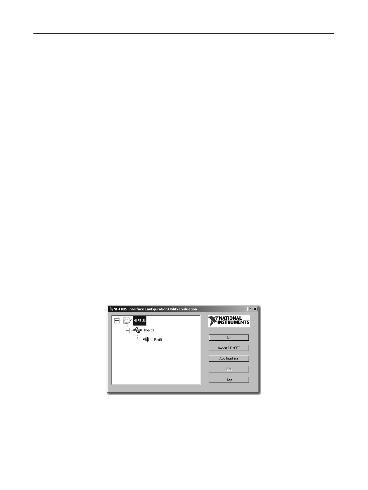
1. Select Start > Programs > National Instruments > NI-FBUS > Utilities > Interface
Configuration Utility and the window appears (Figure 2).
Figure 2 Interface Configuration Utility
12
Page 29
NI-FBUS Software
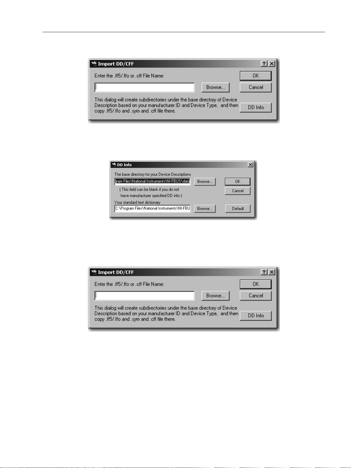
2. Select Import DD/CFF and the browse dialog appears (Figure 3).
3. Click DD Info and the dialog appears (Figure 4).
Installation of Hardware and
Figure 3 Import DD_CFF Browse Dialog
Figure 4 DD Info Dialog
4. Click Browse, navigate to the ValVue installation directory. Default is \\Program Files\DFC\ValVueFF\DD\ and click OK and OK and Figure 5 appears.
Figure 5 Import DD_CFF Browse Dialog
5. Click Browse, navigate to the ValVue installation directory. Default is \\Program
Files\DFC\ValVueFF\DD\FVP until the directory FVP_0001 and FVP_0007
appears. There are three files in the two directories.
6. Select the 0201.ffo file that is under FVP_0001.
7. Select Open.
13
Page 30

GE Energy
ValVueFF Software Interface to FVP
8. Select OK in the Import DD_CFF Browse Dialog and click OK and a dialog appears (Figure 6).
Figure 6 Interface Configuration Utility Success Dialog
9. Click OK.
10. Repeat step 4 through step 9 to import 0306.ffo.
11. Repeat to import DD file in \\Program Files\\....\DD\YVP.
12. Click OK to exit.
After the DDs are installed successfully, they appear in the installation subdirectory of NI-FBUS.
CAUTION The computer and the NIFB interface card with NIFBUS
server software configuration must not conflict with an
operating Foundation Fieldbus segment. Disruption of control
can result. Do not configure the interface as a Link Master.
Configuring a Device with Third Party Software
Fieldbus segments have many devices. Each segment is unique and requires
configuration of the communications and control parameters. Each segment must have a
Link Master that is configured to manage and schedule the communications. The
National Instruments configurator software provides structured access to the parameters.
In this instruction manual screen shots from the National Instruments, Inc. configurator,
NIFBUS Configuration System, version 4.0 are referenced.
Configuring a Valve in an Active Foundation Fieldbus Segment
Because testing a segment can be time consuming it is best to perform the configuration
in a disciplined series of steps. This avoids repeating or repairing configuration steps. You
can refer to the NI-FBUS Configurator User Manual for additional information.
14
Page 31

NI-FBUS Software
Sequencing for Configuration
Use this procedure for sequencing a configuration
1. Set network parameters for Slot time, Max Response Delay, and Inter PDU Delay.
Parameters examples used in the reference model are shown in Table 3. Settings
are different in each Foundation Fieldbus segment.
Table 3 Network Parameters for Reference Model
Installation of Hardware and
Sub Index
1 ST
3 MRD
6 MID
Tag FV
101
Type FVP EJA YTA FVP DLT
Element
Slot Time
Max
Response
Delay
Min Inter PDU
Delay
444 4
12/ST 3 3 3
444 4
FT
102
TT
103
2. Save the as-found configuration.
3. Set node addresses.
4. Assign addresses to the basic devices.
5. Set tag names to unique values.
6. Link function blocks.
LV
201
LT
202
Network Setting Rule Network
Setting
Greatest of each Slot
Time
Greater than 12/ST
Greatest of each Min
Inter PDU Delay
4
3
4
7. Schedule the function blocks.
8. Download the configuration to the devices.
9. Check Clear Devices option in NIFB Configurator download dialog box to remove
bad links.
10. Save a file of the configuration data.
11. Set the devices to their normal states.
Shutting Down ValVueFF
Always close ValVueFF before closing NIFB.
15
Page 32

ValVueFF Software Interface to FVP
This page intentionally left blank.
Page 33

ValVueFF Administration
Overview
This section describes the procedures for installing ValVueFF software. The ValVueFF
installation procedures require a working knowledge of Microsoft Windows, the Masoneilan
FVP positioner, Foundation Fieldbus communications and function block technology. For
additional information about the FVP positioner, see Masoneilan FVP Instruction Manual
(GEA19791_FVP110_IOM).
Administration
ValVueFF Administration, ValVueFF Help, and the FVP Device Instruction Manual are also
installed along with ValVueFF. After successful installation of ValVueFF software, the
System Administrator should:
4
❑ Change the default logon and password.
❑ Set up user accounts through the ValVueFF Administration program.
❑ Secure the ValVueFF CD-ROM in order to provide system security. Anyone with
access to the setup disk could reload the software and thereby get access to FVP
devices.
Installation Sequence
1. Remove existing version of ValVueFF software. ValVue does this for you.
2. Install ValVueFF 2.32 using the instructions in this chapter.
3. Register ValVueFF using the form provided in the software.
17
Page 34

GE Energy
Installing ValVueFF
The following procedure details removing a previous version of ValVueFF and installing
ValVueFF 2.32. Do not install ValVueFF 2.32 until you have installed NI-FBUS 4.X.
Launching the Application
There are several ways to start a ValVueFF 2.32 installation. Depending upon your media
you can use one of the following start options:
1. Select an icon from the CD-ROM.
2. Enter ValVueFF Installer.exe in the Run dialog box.
To install ValVUeFF version 2.32 you must relaunch the application after removing a previous version of ValVueFF.
Removing a Previous Version of ValVueFF
When a previously installed version of ValVueFF is detected by the setup software a
series of messages appear.
ValVueFF Software Interface to FVP
1. Launch the application. The ValVueFF CD Browser window appears (Figure 7).
Figure 7 CD Browser Window
18
Page 35

Removing a Previous Version of
2. Click Install Software and the ValVue FF CD Browser window appears (Figure 8).
ValVueFF Administration
Figure 8 Software Selection Window
3. Click Install Full Edition and the Preparing Setup dialog box appears followed by a
dialog box (Figure 9).
Figure 9 NIFB Version Requirement Reminder
4. Ensure that the fieldbus software is installed, click Yes and the Shut Down message
appears (Figure 10).
Figure 10 Shut Down Message
19
Page 36

GE Energy
ValVueFF Software Interface to FVP
5. Select Yes to continue. The Maintenance dialog box appears (Figure 11).
Figure 11 Select Maintenance Level Dialog Box
6. Select Remove and then Next. A message box appears asking if you want to remove a previous version of ValVueFF.
7. Select Yes. A Setup Status dialog box appears, then a Maintenance Complete dialog box appears (Figure 12).
Figure 12 Maintenance Complete Dialog Box
8. Select Finish.
9. Relaunch ValVueFF to install the application.
20
Page 37

Installing ValVueFF
Installing ValVueFF
1. Launch the application. The ValVueFF CD Browser window appears (Figure 13).
ValVueFF Administration
Figure 13 CD Browser Window
2. Click Install Software and the ValVue FF CD Browser window appears (Figure 13).
Figure 14 Software Selection Window
21
Page 38

GE Energy
ValVueFF Software Interface to FVP
3. Click Install Full Edition and the Preparing Setup dialog box appears followed by a dialog box (Figure 15).
Figure 15 NIFB Version Requirement Reminder
4. Ensure that the fieldbus software is installed, click Yes and the Shut Down message appears (Figure 16).
Figure 16 Shut Down Message
5. Select Yes and the Welcome to ValVueFF dialog box appears (Figure 17).
Figure 17 Welcome to ValVueFF
22
Page 39

Installing ValVueFF
6. Select Next. The License Agreement dialog box appears (Figure 18).
ValVueFF Administration
Figure 18 License Agreement
7. Select I Accept.
8. Select Next. The Choose Destination Location dialog box appears (Figure 19).
Figure 19 Choose Destination Dialog Box
9. Select:
❑ Next to accept the default destination.
OR
23
Page 40

GE Energy
ValVueFF Software Interface to FVP
❑ Change to select an installation location and a browse dialog box appears. Select
a location and select OK.
Ready to Install dialog box appears (Figure 20).
Figure 20 Ready to Install Dialog Box
10. Select Install. A Setup Status dialog box appears (Figure 21), then Setup complete (Figure 22).
Figure 21 Setup Status Dialog Box
24
Page 41

Installing ValVueFF
ValVueFF Administration
Figure 22 Installation Complete
11. Select Finish and a dialog appears (Figure 23).
Figure 23 Use National Instrument Tool Dialog
12. Click OK and ValVueFF CD Browser window reappears.
25
Page 42

GE Energy
Trial Period
ValVueFF Software Interface to FVP
To use this software for a 60 days free evaluation:
1. Open ValVueFF and the Registration dialog appears (Figure 26).
Figure 24 Registration Dialog
2. Leave the Serial Number box blank and select OK in the Evaluation Day dialog box. The evaluation or trial period for the software is 60 days from the first day of use.
3. Select OK and logon in the ValVueFF Logon dialog box (Figure 25). See “Setting User Accounts, System Administration, Passwords, and Privilege Levels” on page 31 for setting up individual ValVueFF accounts and privileges.
Figure 25 Trial Logon Dialog
4. Click OK. A notice appears and tracks the time left for your free trial. You must register within sixty days.
26
Page 43

Registration
Registration
Permanent use of this software requires a license for each computer it is used on. You
must register the software to obtain the software key for your license. If you are using a
trial version and wish to purchase a license contact your Masoneilan representative to
obtain a serial number.
Previous Versions
If you are upgrading from a previous version of ValVueFF you are NOT required to
register the software. Your old registration number populates the registration field for
version 2.32 during the installation process. There is no need to take further action.
Registering ValVueFF Software
Use this procedure to register ValVueFF software.
1. Open ValVueFF, select Help > Registration Info and the Registration dialog
appears (Figure 26).
ValVueFF Administration
Figure 26 Registration Dialog
27
Page 44

GE Energy
ValVueFF Software Interface to FVP
2. Enter your Name, Company and Serial Number, click OK and the Logon dialog appears (Figure 27). The serial number can be found on your purchase order or on the ValVueFF box.
Figure 27 Logon Dialog
3. Select OK and the Software Key dialog box appears (Figure 28).
Figure 28 Software Key Dialog Box
28
Page 45

Registering ValVueFF Software
4. Select HSE Support if you are using an HSE linking device. Leave this selection
blank if you are not using an HSE linking device.
5. Select Registration. The ValVueFF registration form appears (Figure 29).
ValVueFF Administration
Figure 29 Registration Form
6. Complete the registration file.
7. Select Save to File.
29
Page 46

GE Energy
ValVueFF Software Interface to FVP
8. Attach the Registration File to an email and send the email to: softwarereg@ge.com. Our Customer Service department emails you a key for your application (Figure 30).
Figure 30 Software Key Dialog Box
9. Enter your key in the Software Key field.
10. Enter the key for HSE Support if you requested that key and select OK. You are registered.
30
Page 47

Setting User Accounts, System
ValVueFF Administration
Setting User Accounts, System Administration, Passwords, and Privilege Levels
In a plant having many users with various levels of training and responsibility it is often
necessary to restrict users to a limited range of functions depending on their training
and job function. Starting the ValVueFF program requires a valid account with a user
name and a password for each user. The privilege level associated with a ValVueFF
account determines which functions of the program the user is allowed to access.
The ValVueFF Administration program allows the administrator to perform all user
account administrative functions to run ValVueFF and to control access to the
functionality of the FVP positioner. Administrative functions include:
❑ Adding new user accounts
❑ Deleting existing user accounts
❑ Changing existing user accounts
❑ Adjusting privilege levels Starting Administration Program
To start ValVueFF Administration:
1. Select Start > Programs > Dresser > ValVueFF Full Edition > ValVueFF Tool >
ValVueFF Administration. The administrative program prompts you for a logon
name and password. Login in for the first time with an administrator account
(Figure 31).
Figure 31 Admin Logon Dialog Box
2. Enter the default logon name Admin and leave Password blank (case-sensitive).
31
Page 48

GE Energy
ValVueFF Software Interface to FVP
3. Select OK and the VFAdmin dialog box appears (Figure 32).
User Levels
Figure 32 Adding Users in VFAdmin Dialog Box
By default the program contains three accounts:
❑ Admin: The password is case sensitive. The initial password is blank. Use the
administration program immediately to install a password for an Administrator and
make the system secure from unauthorized use.
❑ masoneilan: lower case, and password of new, also lower case.
❑ training: enables use of the FVP process control simulator with the logon name of
training, lower case, and password of training, lower case. The process control
simulator produces a process that has a dead time of one second and a lag of five
seconds. The process controller simulator is useful for training users on the many
functions and features of the FVP positioner and its PID function block.
Each user is assigned an account and each account contains an associated privilege
level. You must provide ValVueFF users with an appropriate privilege level to keep field
devices secure from the actions of unknowledgeable, unauthorized or malicious users. It
is good practice for an Administrator to create a second logon name and password
combination, with a lower privilege level, to use for routine tasks.
Privilege levels range from 0 to 9, with level 0 the lowest and 9 the highest. Table 4
defines the privilege levels that control access to specific functions of the ValVueFF
program. Services that are not accessible to a particular level are grayed out.
32
Page 49

Setting User Accounts, System
Table 4 User Privilege Level Descriptions
Level Privilege Level
Allows the user to logon to ValVueFF only if the connected FVP is in Auto state. The user
Level 0
Level 1
Level 2 This level is not defined.
Level 3
can send commands that reply with configuration, calibration, and status information but the
user cannot change any information. Level 0 users cannot access Out Of Service or Manual
states.
Allows the user access to Auto, Manual or Out Of Service states. The user can transfer from
one mode or state to another, that is, the user can take the FVP out of Auto and put it in
Manual. The user can then set valve position. However, the user cannot change the
calibration or configuration. A level 1 user cannot access the PID dialog box.
Allows the user to change the configuration or calibration values but does not allow the user
to perform calibration and tuning operations that stroke the valve including Find Stops, Auto
Tune, or diagnostics.
The user can open the PID dialog box and use it to change PID modes and move the valve
in manual or change process variable setpoint. The user can enter tuning parameters for the
process variable PID control.
ValVueFF Administration
Level 4 Allows the user to perform all operations except Download Configuration to FVP.
Level 5 This level is not defined.
Level 6 This level is not defined.
Level 7 This level is not defined.
This level is intended for training, use it cautiously. It grants all of the privileges of level 4 plus
Level 8
Level 9
allows access to the Simulation State of the process controller. The simulation of the PID
Block allows the user to run the process controller without connecting a process variable
input to the FVP and is useful for learning how to operate the process controller.
Allows access to all FVP functions. In addition, it is the only level allowed to logon to the
administration program.
The Administrator has an account of privilege level 9. There must be at least one user of
privilege level 9 in order to get access to the Administration program.
WARNING Never use the simulation state if the valve is connected in a
control loop or the if the valve is controlling process flow.
The simulation state permanently removes important control
loop configuration information from the FVP valve
positioner. The soft-wired connection between the PID
functions block and its input function block must be restored
after simulation is used. Reconfigure function block links
after using simulate. The Clear Device command must be
used when downloading restored configuration.
33
Page 50

ValVueFF Software Interface to FVP
This page intentionally left blank.
Page 51

Using ValVueFF
Overview
Integrated Valve Interface (IVI)
The primary screen for displaying information in ValVueFF, the Integrated Valve Interface
screen (IVI) (Figure 33), appears after a successful ValVueFF logon. The IVI displays and
updates real time values for valve position, valve Set Point, actuator pressure, and provides
access to all other services.
The IVI offers tools and wizards using standard conventions and offers multiple paths to
functions to suit a user's preferences. The information and controls for services are
arranged in frames within IVI. You have single click access to the PID Controller interface
from the IVI. The IVI displays and updates real time values for valve position, valve Set
Point and actuator pressure numerically and graphically. The IVI displays all valve and
positioner variables and provides access to services such as Setup Wizard, Configuration,
Calibration and Diagnostics tools.
5
Major screen components include (Figure 33):
1 Menu bar: provide access to services that work with files, devices and function blocks.
2 Icon toolbar; provide access to services that work with files, devices and function blocks.
3 Status bar: displays the status of the fieldbus segment.
4 Device List tree frame: used to navigate to a device.
5 Block Actual Mode frame; list the mode for all configured blocks.
6 Other Para bar frame: shows the schedule Analog Output Block (AO) and PID status and errors
Temperature, Pressure and I/P frame: lists the operational data in bar format Internal
7
temperature, output pressure (optional) and servo output to I/P are displayed as bar-graphs.
Position frame: slider bars to toggle the The Set Point and Tar g et Po i nt slider bars and the
8
Temperature, Pressure and I/P indicators on/off using the View menu. Also shows the Actual
Position.
35
Page 52

GE Energy
1
2
3
4
6
7
8
5
9
10
ValVueFF Software Interface to FVP
9 Selected Device frame: device tag and operational state
Companion Device frame: shows summary information from a second positioner on the same
10
segment as the selected device.
Figure 33 ValVueFF Integrated Valve Interface (IVI)
Menu Bar
Table 5 explains the menu bar functions. The drop down menus and icon tool bar provide
File
access to services that work with files, devices and function blocks.
Table 5 ValVueFF Menu Selections
Menu Menu Item Display
Open File Device Configuration File dialog box used to
display saved configurations.
Save File Allows you to store a configuration in a folder
for later use.
Generate Report A browser containing a template preloaded
with configuration details.
Exit Closes the application and prompts you to save
all unsaved information.
36
Page 53

Menu Bar
Using ValVueFF
Table 5 ValVueFF Menu Selections (Continued)
Menu Menu Item Display
Setup Setup Wizard Setup Wizard dialog box is used to do an initial
setup on a positioner.
Configuration Displays the Configuration dialog box used to
reconfigure a positioner.
Calibration Displays the Calibration dialog box used to
recalibrate a positioner.
Device Tag/Address A dialog box used to change the tag name or
address of a device.
View Toolbar Toolbar at the top of the screen containing
important ValVueFF functions.
Status Bar Information at the bottom of the screen
detailing devices, trends, and queries.
View Trend Trend dialog box displaying a graphical view of
the current selected device. See “PID Block
and Trending Services” on page 119.
PID Controller PID Controller dialog box used to view and
control the PID Process Controller. See “PID
Block and Trending Services” on page 119.
Fail Safe Status Fail Safe Device dialog box that details devices
in Failsafe mode. See “Failsafe Handling” on
page 173.
Device Op State Change the operation state of a selected
device. See “Device Tag/Address” on page 57.
Companion Device Permits selection and enabling of a er device.
See “Companion Device Display Frame” on
page 44.
Servo Output to I/P Toggles the I/P slider bar display, the third of
the three slider displays.
Pressure Toggles the Pressure slider bar display, the
second of the three slider displays.
Temperature Toggles the Temperature slider bar display, the
first of the three slider displays.
Other Para Bar Toggles the blank double window at the bottom
of the screen.
Clear Comm Error Clears the list of FF Command errors that have
been collected.
37
Page 54

GE Energy
ValVueFF Software Interface to FVP
Table 5 ValVueFF Menu Selections (Continued)
Menu Menu Item Display
Tools Diagnostics Diagnostics dialog box used to diagnose a
selected device.
Query Device Query dialog box used to display a selected
device.
Re-Scan Devices Scan dialog box used to rescan the link for a
list of all devices.
Download Downloads the current configuration into a
selected device.
Download Firmware Downloads new firmware into a selected
device.
Set as Link Master Dialog box used to set a device as a link
master.
Reboot Device Dialog box used to restart a connected device.
Reboot device is available only to
Administrators.
For current selected device, if it is running as
LAS, a message refusing the reboot operation
appears.
Close Device Dialog box used to shut down a connected
device.
Help Help Topics The ValVueFF Help system.
About ValVueFF Returns a message box with ValVueFF version
number and copyright notice
Registration Information Registration information used to register this
software application.
38
Page 55

Icon Toolbar
Icon Toolbar
Each menu selection that displays a dialog box has a corresponding Toolbar Icon
(Table 6). A greyed out icon means the functionality does not apply to the currents
application or that you don’t have the requisite permission level.
Tool Tips Feature
When you place the cursor on an icon a Tool Tip message displays the function of the
selected icon. Similarly, if you place the cursor on a menu selection without clicking, a
Status Bar message appears describing the function or action about to be selected.
These features are displayed in Figure 34 and Figure 35.
Using ValVueFF
Figure 34 Tool Tips Message
Figure 35 Status Bar Message
Table 6 Toolbar Icons
Icon Definition
Open Configuration File - Displays the Open Configuration Device dialog box that can
access previously used configurations.
Save Configuration File - Displays the Save Configuration Device dialog box used to
archive previously used configurations.
Download Configuration - Opens a dialog box used to download an existing
configuration from your PC.
Generate a Report File - Opens a dialog box used to generate a summary report of all
configuration parameters.
39
Page 56

GE Energy
Icon Definition
ValVueFF Software Interface to FVP
Table 6 Toolbar Icons (Continued)
Setup Wizard - Opens a dialog box used to set up a valve positioner. This feature is
useful if you are setting up a valve for the first time.
Configuration Management - Opens a dialog box containing six tabs that is used to for
device configuration. The tabs are General, Position, Actuator, AO Block, PID Block and
Options.
Calibration Management - Opens a dialog box used to adjust a positioner to the actual
stroke of a valve. Tabs include Range, Tuning, Travel Calibration, and Advanced.
Diagnostics - Opens a dialog box used to perform actuator and positioner signature test
procedures. Real time diagnostic test data is also displayed here.
Change Device Operation State - Opens a dialog box used to switch between operating
states. The operating states are Normal, Manual, and Out of Service.
Query Device - Opens a dialog box used to access device data in predefined categories.
The two tabs area General and Block Parameters.
Trend - Returns a dialog box used to display real-time data from polled devices.
PID Process Controller - Returns a dialog box used to manage the PID function block.
Rescan the Field Bus Segment - Returns a dialog box used to refresh connections to all
working devices in the fieldbus segment.
About ValVue FF Version - Returns a dialog box that displays a version number for
ValVueFF and a copyright notice.
40
Page 57

Positioner Faceplate
Positioner Faceplate
The positioner faceplate frame contains controls used for working with a positioner.
Some of the faceplate features can be toggled on and off. When a feature is active a
check mark displays next to the features description on the View menu.
Figure 36 shows an inactive positioner faceplate with features turned off. Figure 37
shows an inactive positioner faceplate with all feature turned on. Features are toggled
using selections on the View menu.
Features that can be toggled on and off include:
❑ Toolbar ❑ Status Bar ❑ Servo Output to I/P ❑ Pressure ❑ Temperature ❑ Other Parameter Bars
Using ValVueFF
Figure 36 IVI Positioner Faceplate Frame - Functions Turned Off
41
Page 58

GE Energy
ValVueFF Software Interface to FVP
Figure 37 IVI Positioner Faceplate Frame - Functions On
42
Page 59

Active Faceplate
Active Faceplate
Figure 38 shows an active Positioner Faceplate frame with complete functionality:
❑ The control valve tag is shown in the PD-Tag field.
❑ The current operating state of the positioner is shown in the Operation field. In
❑ Block Mode Actual displays individual block modes appear for each of the
❑ The valve position Set Point appears next to the graphical position of a slider
❑ Below the Set Point display, the target position and actual position are shown as
The Target Position is obtained from the Set Point signal using parameters defined
using Configure (see page 79), from valve characterization and the configuration of
air-to-open or air-to-close, also defined in Configure. It is further modified by any
configured limits. In Figure 38 the incoming setpoint and the target position differ as an
equal percent characteristic is used. If a linear characteristic and air-to-open are
configured, with limits configured outside the possible range of position, the Targ et
Position is equal to the Set Point.
Using ValVueFF
this example the display reads, NORMAL STATE.
positioners internal function blocks.
control, numerically to two decimal places.
a slider and bar, respectively, with values shown to two decimal places.
Figure 38 IVI Faceeplate in Normal State
43
Page 60

GE Energy
Companion Device Display Frame
The Companion Device frame (Figure 39) displays and updates real time values for
transducer block mode, target position, and valve position. Use it to observe summary
information from a second positioner connected in the same segment as the selected
device.
To select a companion device:
1. Choose a focus device selected and viewed in the Selected Device frame.
2. Select View > Companion Device > Select or right-click a non-selected device to access the Select/Deselect as Companion dialog box. The companion device must be an FVP valve positioner connected to the same segment as the selected device.
Fields
Tag The physical device tag of the selected companion device.
ValVueFF Software Interface to FVP
TRANSDUCER BLOCK (TB) Mode
Target Position The target valve position of the selected companion device.
Actual Position The actual valve position of the selected companion device.
The actual mode of Transducer Block (TB) of the selected companion device.
Figure 39 Companion Device
44
Page 61

Status Frame
Status Frame
The Status Frame (Figure 40) displays Analog Output Block (AO) and PID block
scheduling status. In addition, the transducer block error (XD ERROR) appears. The
communication error text box accumulates error messages that can be copied to a text
file for analysis. To clear the error text box select View > Clear Comm Error Display.
Selected Device Frame
The Selected Device frame (Figure 41) provides a dedicated view for a specified
device. The view includes device tag and operation state, block actual mode, valve
position and Set Point, and other status and parameters bar graph. It encloses displays
and controls for working with the positioner and control valve. The individual
components are explained elsewhere.
Using ValVueFF
Figure 40 Status Frame
Each of the parameters displayed in the control faceplate dialog has a function block
and parameter name (shown in the form of BLOCK.PARAMETER). These are listed in
Table 7.
Figure 41 Positioner Faceplate with =% Characteristic
45
Page 62

GE Energy
ValVueFF Software Interface to FVP
Table 7 IVI Faceplate Parameters
Display Display
Type
PD - Tag [PD.TAG] This indicates the FVP tag
Operational
State
Active
Control
Device Operation State can be one of
the following:
Parameter Name Remarks
❑ NORMAL ❑ MANUAL ❑ Out of Service
If no physical device is selected
OFFLINE is displayed as the operation
state.
Setpoint
Signal
Tar ge t
Position
Valve Position Bar and
Temperature Bar and
Slider and
XX.XX%
XX.XX%
XX deg
[AO.OUT] Desired valve position before
application of characterization and
limits.
TB.FINAL_POSITION Desired valve position as derived by
the FF input value into the FVP.
TB.FINAL_POSITION _VALUE This indicates valve stem or shaft
position in percent of ranged travel.
TB.ELECT_TEMP Device environmental temperature
[-40, 85] °C or [-40, 185] °F
Color: Yellow
Pressure Bar and
XX.XX
PSI
I/P Bar and
XX.XX%
Block Modes Color
coded
individual
boxes
TB.OUT_PRESSURE FVP output pressure for a S/A
positioner or diff. pressure for a D/A
positioner. Blue color.
Scale=TB.SPRING_RANGE
TB.SERVO_OUTPUT_SIGNAL 80 - 100% = Red 20 - 80% = Green 0 -
20% = Yellow
Block.MODE_BLK
Block = RB, TB, AO, DI, or PID
AUTO, Cas
RCas = Green
OOS = Red
MAN = Yellow
46
Page 63

Device Selection
Block Actual Mode
Table 8 lists the supported modes of the valve positioner for each block.
Resource Auto, O/S
Transducer Auto, O/S
AO RCas, Cas, Auto, Man, (LO), (IMAN), O/S
DI Auto, Man, O/S
OS Cas, Auto, (Iman), O/S
PID ROut, RCas, Cas, Auto, Man, (LO), (IMAN), O/S
Device Selection
All of the devices on the bus segment live list are shown as icons in the Device
Selection box. Select any device to open a communications session with the positioner.
The fieldbus segment live list is continuously scanned and devices are shown when
present. Devices that have communications failure are shown with a red X. The
selected device is shown with a red checkmark in Figure 42.
Using ValVueFF
Table 8 Block Modes
Block Supported Modes
Figure 42 Device Selection Dialog Box
When a device is selected a warning dialog box informs that an attempt is made to
connect to a new device. Then the Read configuration dialog box displays progress
uploading device data.
47
Page 64

GE Energy
The Device Selection popup menu (Figure 43) offers direct access to services. Right-click
on the device to access this menu.
Figure 43 Device Selection Popup for Tag/Address
Using ValVueFF Menu Selections
ValVueFF Software Interface to FVP
ValVueFF services are accessed using three standard Windows techniques. The Device
Selection with popup menu is shown in Figure 44.
Figure 44 Device Selection with Popup Menu
Tools Menu Select with a left mouse button click on menu and then select a
menu item from the drop down list.
Toolbar Icon Select with a single left mouse button click on the icon.
Device Selection with Popup Menu
Right-click on the desired device.
48
Page 65

Setup Menu
Setup Menu
Menus items include:
❑ “Setup Wizard” on page 49
❑ “Configuration Services” on page 55
❑ “Calibration Services” on page 56
Setup Wizard
The Setup Wizard provides (Figure 45), in a single tool, all the services for
commissioning a valve positioner. It includes a sequence for configuration and tuning. It
is most useful for first time setup of the positioner. Follow the step-by-step instructions
in five dialog boxes to quickly complete the setup and to start running the valve. The
dialog box parameters are detailed in the next two chapters of this manual. The process
includes:
❑ “Actuator Wizard”
Using ValVueFF
❑ “Tuning Wizard” on page 51
❑ “Travel Calibration Wizard” on page 52
❑ “Position Control Limits - Wizard” on page 53
❑ “Finish Setup Wizard” on page 54
Figure 45 Setup Wizard
49
Page 66

GE Energy
Actuator Wizard
Use the Setup Wizard setup page (Figure 46) to configure the Transducer Block (TB)
valve actuator information. For a description of the parameters, refer to “Actuator Page”
on page 87.
ValVueFF Software Interface to FVP
Figure 46 Actuator Wizard
50
Page 67

Setup Wizard
Tuning Wizard
Use the Tuning step to execute the combination of Search Stops + Auto Tune described
in “Tuning Tab” on page 109 (Figure 47).
Using ValVueFF
WARNING Tuning strokes the valve over its entire travel. Isolate the
valve from the process prior to calibration
Figure 47 Tuning Wizard
51
Page 68

GE Energy
Travel Calibration Wizard
Use the Travel Calibration page (Figure 48) to calibrate the 0%, 50% or 100% position
points, when necessary. For a description of all the parameters and controls, refer to
“Travel Calibration Tab” on page 112.
ValVueFF Software Interface to FVP
Figure 48 Travel Calibration Wizard
52
Page 69

Setup Wizard
Position Control Limits - Wizard
Use the position control limits page (Figure 49) to change the position limit setting for
the valve position configuration parameters in Transducer Block (TB). The parameters
are detailed in “Position Limits Parameters” on page 75.
Using ValVueFF
Figure 49 Position Control Limits Wizard
53
Page 70

GE Energy
Finish Setup Wizard
This is the final screen (Figure 50) and indicates that the basic setup is valid and provides
a choice of Device Operation States before completing setup. The setup is not completed
until Finish is selected.
ValVueFF Software Interface to FVP
Figure 50 Setup Wizard Finished
54
Page 71

Configuration Services
Configuration Services
The General tab on the Configure window (Figure 51) includes the Device Info, Block
Tag Info, and Others Installed. The other tabs on this window are:
❑ Position for configuring position limits and switches.
❑ Actuator for configuring valve action and limits.
❑ AO Block for configuring block setpoints and status options.
❑ PID Block for configuring block parameters, setpoint limits and status options.
❑ Options for configuring characterization type and setting units.
See “Configuration Services” on page 79 for detailed information.
Using ValVueFF
Figure 51 Configuration Dialog Box
55
Page 72

GE Energy
Calibration Services
The Calibration page (Figure 52) contains the following tabs:
❑ Range: Use to adjust the positioner to the actual stroke (range) of the valve.
❑ Tuning: Use to Auto Tuning the position control algorithm.
❑ Travel Calibration: Use to make additional adjustments to valve stroke.
❑ Advanced: Use to set non-linear factors to optimize dynamic performance.
ValVueFF Software Interface to FVP
Figure 52 Calibration Dialog Box
See “Calibration Services” on page 105 for detailed information.
56
Page 73

Device Tag/Address
Device Tag/Address
To change the node address or PD-Tag of any device listed in Device Selection:
1. Either:
❑ Right-click the device to bring up the context menu.
or
❑ Select Setup > Device Tag/Address.
2. Enter a unique Device Tag for the entire control plant.
3. Select a Node Address unique in the segment from the dropdown list of allowed
addresses. Use only the allowed address to avoid communications errors.
Using ValVueFF
CAUTION Changing the device tag/address clears the linkage and
trend configuration in the device and may interrupt the
device operation.
Figure 53 Tag/Address Dialog
57
Page 74

GE Energy
View Menu
Menus items include:
View Trend
Use the Trend dialog (Figure 54) to see a graphical view of the current selected device.
This can be accessed from the menu or the Device Selection right-click menu. The trend
can be customized to display certain data and data ranges.
ValVueFF Software Interface to FVP
❑ “View Trend” on page 58
❑ “PID Controller” on page 59
❑ “Device Operation State” on page 61
Figure 54 Trend Dialog
See “PID Block and Trending Services” on page 119.
58
Page 75

PID Controller
PID Controller
The PID Process Controller dialog box (Figure 55) contains the tools for managing the
PID function block. It is composed of frames that group controls and displays:
Using ValVueFF
❑ The PID Status frame displays and controls the PID States (block modes),
Setpoint and Process Variable, and the Device tagname. In Manual State (M),
drag the PID output slider to move the valve. In Local State (L), drag the Setpoint
Slider (or enter a value in the Setpoint text box) to change the process variable
Set Point. In Cascade (C), and in Remote cascade (R), the Set Point is
controlled by a function block or remote application.
❑ Others frame: Click Change to access the Change PID Parameter dialog to tune
the P, I and D parameters. The Alarm Status fields display the actual pressure,
cascade and remote cascade setpoints and turn red when in alarm.
❑ PID Output and Valve Position: Use the slider to tune the PID output and see the
valve position above.
Figure 55 PID Process Controller Dialog Box
59
Page 76

GE Energy
Change PID Parameters
The process loop tuning parameters are displayed in a frame (Figure 56). To change
them:
1. Select Change, this displays the Change PID Tuning Parameters dialog box.
2. Tune while in the controller is one of the automatic control modes, L, C, or R, or when in Manual, or Other.
ValVueFF Software Interface to FVP
Figure 56 Change PID Tuning Parameters Dialog Box
60
Page 77

Device Operation State
Device Operation State
This dialog box (Figure 57) controls switching between the block modes as defined by
the Operation States.
❑ Normal - The valve is controlled by the control configuration set in Foundation
Fieldbus.
❑ Manual - The valve position can be set from ValVueFF.
❑ Out of Service - The valve position is controlled at the last Set Point but does not
respond to inputs.
Using ValVueFF
Figure 57 Device Operation Dialog Box
61
Page 78

GE Energy
Tools Menu
❑ “Diagnostic Services” on page 62
❑ “Query Device” on page 63
❑ “Rescan Devices” on page 64
Diagnostic Services
Diagnostics (Figure 58) provides controls to perform actuator and positioner signature
test procedures. It also displays the continuous diagnostic data that is an accumulation of
valve service history. Refer to “Diagnostic Services” on page 135 for detailed information.
ValVueFF Software Interface to FVP
Figure 58 Diagnostic Services DIalog Box
62
Page 79

Query Device
Query Device
Use the two tabs in the Device Query (Figure 59) to read parameters stored in the FVP.
The General tab accesses general data, while the Block Parameter tab displays all
parameters in each function block.
There is a query window available for each device. You can open multiple query
windows for multiple positioner devices at the same time. The query window can be run
while accessing other windows.
Use the General page to access device data in predefined categories:
1. Select the category name from the drop down list box.
2. Select Read to display all the parameter values in the category.
Using ValVueFF
Figure 59 Device Query Dialog Box
Use the Block parameters page:
1. Select a block in Select Block.
2. Select Read to display all the parameter values.
63
Page 80

GE Energy
Rescan Devices
Selecting or Tools > Re-scan Devices refreshes the connections to all working
devices on the field- bus segment (Figure 60) and closes the opened device. You lose
control until you have reselected a device. You are prompted to confirm that a rescan is
acceptable.
Multi-Link Environment
ValVueFF Software Interface to FVP
Figure 60 Rescan Message Box
ValVueFF can only work with one segment each time. In a multiple link segments
environment, before the IVI appears, a dialog appears (Figure 62):
Figure 61 Link Selection
To open a link in a multi-link environment:
64
Page 81

Help Menu
Using ValVueFF
Figure 62 Link Selection
1. Select segment.
2. Click OK.
Help Menu
This consists of:
About
Selecting the About icon or selecting Help > About ValVueFF displays the version of
ValVueFF and the copyright notice (Figure 63).
❑ “About” on page 65
❑ “Registration Info” on page 65
❑ “Registration Info” on page 65
Registration Info
Select Help > Registration Info to open the ValVueFF Registration dialog.
Figure 63 About ValVueFF Message Box
65
Page 82

GE Energy
Offline Use of ValVueFF
Choose Offline to work with configuration files when not connected to a positioner. Offline
services allow files to be copied and modified as preparation for download to active
devices. The user permission levels restrictions apply to offline use the same as when
working with FVP positioners.
ValVueFF Software Interface to FVP
66
Page 83

Setup Wizard Procedure
The Setup Wizard (Figure 64) is recommended for installing and configuring an FVP
positioner. It is comprised of up to six steps:
❑ “Step 1: Welcome” on page 68 (required)
❑ “Step 2: Actuator Wizard” on page 69 (required)
❑ “Step 3: Tuning Wizard” on page 70 (required for initial valve configuration)
❑ “Step 4: Travel Calibration Wizard” on page 72
❑ “Step 5: Position Control Limits Wizard” on page 75
❑ “Step 6: Finish Setup Wizard” on page 77 (required)
6
67
Page 84

GE Energy
Step 1: Welcome
To use the wizard:
1. Select Setup > Setup Wizard or click and the Welcome window appears (Figure 64).
ValVueFF Software Interface to FVP
Figure 64 Setup Wizard Dialog Box
2. Select Next and the Actuator window appears (Figure 65).
68
Page 85

Step 2: Actuator Wizard
Step 2: Actuator Wizard
1. Select the Valve Action, Actuator Type, Relay Type, and Valve Type (Figure 65).
Setup Wizard Procedure
Figure 65 Actuator Wizard Dialog Box
2. Select Next to begin calibration and tuning.
NOTE If linear is incorrectly selected, when the valve is rotary, a
large angle error message displays. To correct this use the
Configure Actuator dialog box followed by the Calibration
Services Tuning dialog box.
Do not Auto Tune if manual tuning has been used. Auto Tune creates new parameters that override the manual tuning parameters.
WARNING Before beginning the Auto or Manual range calibration,
confirm that the valve is isolated from the process. This
procedure exhausts and then fills the valve actuator to
supply pressure and therefore strokes the valve over its full
range. Supply pressure MUST NOT exceed the actuator
pressure rating marked on the actuator. Positioner supply
pressure MUST BE at least 5 psi higher than the upper
spring range of the valve.
69
Page 86

GE Energy
Step 3: Tuning Wizard
The positioner automatically searches for the mechanical valve travel limits and tunes the
valve position PID control algorithm (Figure 66).
ValVueFF Software Interface to FVP
Figure 66 Tuning Wizard Dialog Box
1. Ensure the air supply to the valve must be on and set to the correct pressure.
2. Select Go. This takes several minutes to complete and strokes the valve. If this is not
a first time setup of the valve, skip this step by selecting the Skip button. The
following list details actuators that must be tuned manually. Look for a Manual Tune
Only notice in the TB block tag descriptor. Actuators that may require manual tuning:
❑ Actuators with internal leaks, such as pistons.
❑ Large actuators with high spring ranges.
Auto Tune is successful for most valves. However, very large actuators or high hysteresis
may require manual tuning. If Limit Searching and Auto Tune are performed successfully
the Tuning Result dialog box displays for your confirmation (Figure 67).
70
Page 87

Step 3: Tuning Wizard
Setup Wizard Procedure
Figure 67 Tuning Results Dialog Box
3. Select Accept applies new parameters or select Not Accept to keep your original
parameters.
If the tuning fails there is an additional message describing why the failure occurred. If
the self calibration and Auto Tune procedures are unsuccessful there is a message
(Figure 68).
Figure 68 Tuning Wizard Message Boxes
71
Page 88

GE Energy
Figure 69 Tuning Wizard Error Message Boxes
NOTE Before running the Travel Calibration Wizard checks that Tight
Shut Off, Full Open, and Position Limits are disabled. Select
Next to see the Position Control Limits Wizard, shown in
Figure 71. Select Back to return to the Travel Calibration
Wizard. If changes are needed select Next to complete the
Wizard and install the changes. Restart the Setup Wizard.
Step 4: Travel Calibration Wizard
ValVueFF Software Interface to FVP
The mechanical stops on some actuators may allow the valve to move beyond it's rated
travel. The next wizard allows adjustment of the valve travel to correspond to the travel
indicator on the actuator. In the example shown the valve has been moved to 100% travel
mark on the actuator by trial and error. The FVP positioner indicates that the position
corresponding to 100% rated travel is 93.5% of the measured mechanical travel. If this is
correct select the span control and select Apply Calibration. Select Yes to the
confirmation dialog box Are you sure you want to apply travel calibration?. This method is
also used to adjust the 0% position to correspond to the valve's actual closed position and
to correct nonlinear travel by adjusting the position at which the valve is 50% open.
If Travel Calibration is used to modify valve travel, the initial values shown in Figure 70
may require corresponding modifications. For example, if the travel has been short
stroked so that at 100% calibrated travel the valve is at 80% of mechanical limits,
increase the Full Open Above and Position Upper Limit values to 138% (110%/.8).
Similarly, if the valve is calibrated to allow over-travel at the valve seat, reduce Tight
Shutoff and Position Lower Limit. For example, if the valve is closed at 12% of
mechanical travel, then reduce TS and Position Low Limit to -22%.
72
Page 89

Step 4: Travel Calibration Wizard
Setup Wizard Procedure
Figure 70 Travel Calibration Wizard
CAUTION Supply pressure must not exceed the actuator pressure
rating marked on the actuator. Positioner supply pressure
must be at least 5 psi higher than the upper spring range of
the valve.
WARNING Isolate the valve from the process and keep clear of moving
parts before using Limit Searching or Auto Tune.
To run the Travel Calibration Wizard:
1. Check that the Tight Shut Off, Full Open Features, and the Position Limits are
disabled by:
a. Clicking Next and the Position Control Limits window appears.
b. Setting parameters to disable the above, close and reopen the wizard and
navigate back to the Travel Calibration.
CAUTION These values alter the valves performance. Use them with
caution.
73
Page 90

GE Energy
ValVueFF Software Interface to FVP
2. Perform a Select Calibration Type at Target Position, if required, by:
a. Clicking either:
❑ 0% Calibration
❑ Span Calibration
❑ 50% Calibration
b. Clicking Apply Calib.
3. Perform a Pick Target Position for Calibration, if required, by:
a. Clicking either:
❑ 25
❑ 10
❑ 1
❑ 0.1
❑ 0.01
b. Using the Change To up/down arrows to select a Targ et P os.
c. Clicking Apply Calib. and the Result appears.
4. Select Next.
74
Page 91

Step 5: Position Control Limits
Step 5: Position Control Limits Wizard
To use this:
1. Enter values as required in Figure 71, referring to the descriptions given in
“Position Limits Parameters” on page 75.
Setup Wizard Procedure
Figure 71 Position Control Limits Wizard
2. Select Next.
Position Limits Parameters
Tight Shutoff Below (%)
Full Open Above (%) If the valve position Set Point is more than this value the valve
Position Lower Limit (%)
Position Upper Limit (%)
If the valve position Set Point is less than this value the valve is
forced to fully close. As a general practice this is set between 1
and 3 to minimize seat leakage. The dead band is a function of
this setting, typically between 1/10th and 1/100th of the setting.
The TSB feature is designed to prevent leakage of valves when
the Set Point is 0%.
is forced to fully open.
The valve position Set Point cannot be less than this value. This
prevents the valve from closing. Use only when required by the
control strategy.
The valve position Set Point can not exceed this value. This
prevents the valve from closing.
75
Page 92

GE Energy
ValVueFF Software Interface to FVP
Near Closed Value (%)
Limit Switch Threshold
NOTE When Tight Shutoff Below is configured to a positive value
Fault Control
The threshold below which the valve is considered near closed.
Near Closed is useful for estimating when to change the valve
trim. This value does not effect valve travel it is used only for
reporting the time that valve is near the seat.
The limit switch thresholds apply to the Discrete Input Block (DI)
Set Points.
❑ Threshold Low -Threshold for low limit switch that is
communicated by the Discrete Input Block (DI).
❑ Threshold High -The threshold for the high limit switch that
is communicated by the Discrete Input Block (DI).
small flows are not controllable.
When Full Open Above is configured to a value of less than 100% large flows are not controllable. At the configured Full Open Above setting the flow jumps to the greatest possible value.
❑ Error Band - The position deviation limit to start deviation
timer of Time 1 and Time 2.
❑ Time 1 - Position deviation time limit to show the block
alarm. A negative value turns off this function.
❑ Time 2 - Position deviation time limit to trigger the failsafe
action. Enter -1 to disable the function. A negative value
turns off this function. Using Time 2 failsafe can result in
unwanted process shutdowns.
CAUTION Use the Time 2 failsafe only for a critical process that must be
forced to its failsafe position if the valve is unable to respond
to its position setpoint after a reasonable time delay. Do not
set the error band to a value that is too small. If time 2 is used
it must be longer than the valve stroking time. TIme 2 value
that is too small results in nuisance failsafe behaviour
76
Page 93

Step 6: Finish Setup Wizard
Step 6: Finish Setup Wizard
This screen (Figure 72) indicates that the setup is valid:
1. Select a Device Operation State.
Setup Wizard Procedure
2. Select Finish.
Figure 72 Finish Setup Dialog Box
77
Page 94

ValVueFF Software Interface to FVP
This page intentionally left blank.
Page 95

Configuration Services
Configuration
Configuration services provide the tools to read and set a large number of parameters
required for successful communications and control. Each set of tools is grouped in a
tabbed page. The Configuration dialog box contains six tabs (Figure 73):
General Used to name and describe function blocks and related devices.
Position Used to setup configuration parameters.
Actuator Used to set advanced position control parameters.
AO Block Used to control Set Point limits
PID Block Used to set parameters in the PID block
7
Options Used to configure remaining settings including pressure range and bumpless
transfer.
Figure 73 General Tab - Configuration Dialog Box
79
Page 96

GE Energy
General Page
Use the General tab to enter tagnames for each of the function blocks in the PIDFVP and
to enter a valve or positioner description.
Device Info
Tag The physical device tag (PD-Tag). The device tag is defined in
ValVueFF Software Interface to FVP
CAUTION Don't turn off power for 60 seconds after writing configuration
data. Data cannot be saved. See the positioner instruction
manual.
Do not change Device Tag or Node Address while the NI Configurator or other host software is running. Only change Network parameters when configuring a positioner connected to a segment that is not controlling a process.
Foundation Fieldbus as a string of 32 characters, maximum. The
tag must be unique in the entire control network. When a device
is selected this field grays as read only. The device tag change is
done in the main screen (IVI) by selecting the Tools menu or by
right-clicking the device icon in Device Selection. Always change
device tag with the device off control. Use a configurator to connect function blocks after a tag change.
Node Address The node address of the physical device on the fieldbus segment.
The device address is defined in Foundation Fieldbus as a value
between 1 and 255. The address must be unique in the segment.
When a device is selected this field grays out as read only. The
device address change is done in main screen (IVI) by selecting
the Tools menu or by right-clicking the device icon in Device
Selection.
Link Master devices are normally at addresses beginning with
0x10 (16). Basic devices are normally at addresses 0xE0 (224) to
0xF7 (247). Addresses 0xF8 (248) to 0xFF (255) are reserved for
visitor devices which are automatically reassigned to a basic
device address. Refer to address range definition in Foundation
Fieldbus specification.
Device ID This number consists of manufacturer id number, device number
and device model related number. It is unique in all the devices
among manufacturers and is read only.
Manufacturer ID The 6 digits number of the device manufacturer ID is assigned by
the Fieldbus Foundation and is read only.
Device Type The type of the device is read only.
Device Rev. The revision of the device is read only.
80
Page 97

Block Tag Info
D. D. Rev. The revision of the Device Description is read only.
Model The model of the device is read only.
Descriptor Use this field for a device description or for a memo (28 char.
Block Tag Info
Each block is assigned a default tag-name that should be renamed by the user.
RB The tag of the device resource block.
TB The tag of the device transducer block.
AO The tag of the device analog output block.
DI1 The tag of the device discrete input 1 block.
DI2 The tag of the device discrete input 2 block.
PID The tag of the device PID block.
SPLT The tag of the device Output Splitter Block.
Configuration Services
max).
Others Installed
PID Block Checked when the device PID block is activated. Read only.
Pressure Sensor Checked when the device pressure sensor is installed. Read
Link Master Used to control communications on the fieldbus.
Signature Used to measure and maintain characteristic data.
CAUTION Do not change the device tagname or the node address of a
device in an operating Foundation Fieldbus segment.
Control linkages are lost. Do not use a leading space in a
device tag name, this causes the device to become
non-operational. Block tags are not used for control
linkages. They can be changed without losing control
linkages. However, some applications require restarting if
another application changes a block tag.
only.
81
Page 98

GE Energy
Position Tab
Use this tab (Figure 74) for the setting up the Transducer Block (TB) valve position
configuration parameters.
ValVueFF Software Interface to FVP
Figure 74 Position Tab - Configuration Dialog Box
Servo Parameters Frame
The servo parameters are normally set by Auto Tune in Tuning or Calibration. They
determine the dynamic response of the valve position control.
82
Page 99

Servo Parameters Frame
Advanced Position Configuration
This is the read-only page (Figure 75) for Transducer Block (TB) advanced position
control parameters. To modify the value of any parameter, go to “Advanced Tab” on
page 115.
Configuration Services
Figure 75 Advanced Servo Tuning Parameters
Advanced Servo Tuning Parameters
Boost On Threshold 1 Control parameter to reduce the effect of deadband in the con-
Boost On Threshold 2 Control parameter to reduce the effect of deadband in the con-
Boost Off Threshold 1 Control parameter to reduce the effect of deadband in the con-
Boost Off Threshold 2 Control parameter to reduce the effect of deadband in the con-
Boost Value 1 Control parameter to reduce the effect of deadband in the con-
Boost Value 2 Control parameter to reduce the effect of deadband in the con-
Servo I Sleep Limit Control parameter to prevent unnecessary overshoot for large
Servo P Alpha Control parameter to adjust the gain under very large hysteresis
trol relay.
trol relay.
trol relay.
trol relay.
trol relay.
trol relay.
step inputs.
condition.
Internal Gain Displays the total gain for the I/P module, control relay and
valve.
Servo Offset Initial value of the integrator.
83
Page 100

GE Energy
Position Limits Frame
Use the Position Limits frame (Figure 74) parameters to limit the valve, force the valve to
close tightly or open fully at specified positions, and to set the trip points of the limit
switches (DI block). You can also activate a warning when a deviation lasts longer than
Time 1 or to force the valve to it's failsafe position if the deviation lasts longer that Time 2.
CAUTION Position Limit parameters are powerful tools to alter the valve
ValVueFF Software Interface to FVP
performance to be non-linear. Use them with caution and only
when the process requires special performance.
When Tight Shutoff below is configured to a positive value, small flows are not controllable.
Tight Shutoff Below (TSB)
If the valve Target Position is less than this value, the valve is
forced to fully close. A value of -10 removes this function from the
normal travel range, unless the calibration of valve travel has
been readjusted. Set this between 1 and 3 to minimize seat leakage.
Full Open Above (FOA)
If the valve Target Position is more than this value, the valve is
forced to fully open. A value of 110 removes this function from the
normal travel range.
Position Lower Limit The valve Target Position must not be less than this value. This
prevents the valve from closing. Use only when required by the
control strategy. A value of -10 removes this function from the
normal travel range.
Position Upper Limit The valve Target Position must not exceed this value. A value of
110 removes this function from the normal travel range.
CAUTION Use of Full Open Above at values less than 110 can result in
rapid increase in flow rate if input reaches this value. Use with
extreme caution.
Near Closed Value The threshold below which the valve is considered near closed.
Near Closed is useful for estimating when to change the valve
trim. This value does not effect valve travel it is used only for
reporting the time that valve is near the seat.
Determining Values to Disable Tight Shutoff Below, Full Open Above, and Limits
If Travel Limits have been readjusted after performing Find Stops, then the values that
disable the Tight Shutoff Below, Full Open Above, Position Lower Limit, and Position
Upper Limit functions must be determined by testing the limits. To disable these functions,
set them 10% above the full open mechanical stop position or 10% below the fully closed
mechanical stop position.
84
 Loading...