

Page 1

GE Oil & Gas
GE Data Classification: Public
Masoneilan* Valves
ValVue* ESD
Instruction Manual
Digital communications
software designed
exclusively for SVI* II ESD
Page 2

About this Guide
This instruction manual applies to the following instruments and approved software:
SVI II ESD
with Firmware version
with ValVue ESD version 1.0 or greater
with a handheld communicator with DD published for SVI II ESD
The information in this manual is subject to change without prior notice.
The information contained in this manual, in whole or part, shall not be transcribed or copied without GE Oil & Gas’s written
permission.
In no case does this manual guarantee the merchantability of the PST Controller or the software or its adaptability to a spe-
cific client needs.
Please report any errors or questions about the information in this manual to your local supplier or visit
www.ge-energy.com/valves.
DISCLAIMER
THESE INSTRUCTIONS PROVIDE THE CUSTOMER/OPERATOR WITH IMPORTANT PROJECT-SPECIFIC REFERENCE INFORMATION IN ADDITION TO THE CUSTOMER/OPERATOR’S NORMAL OPERATION AND MAINTENANCE PROCEDURES. SINCE
OPERATION AND MAINTENANCE PHILOSOPHIES VARY, GE (GENERAL ELECTRIC COMPANY AND ITS SUBSIDIARIES AND
AFFILIATES) DOES NOT ATTEMPT TO DICTATE SPECIFIC PROCEDURES, BUT TO PROVIDE BASIC LIMITATIONS AND
REQUIREMENTS CREATED BY THE TYPE OF EQUIPMENT PROVIDED.
THESE INSTRUCTIONS ASSUME THAT OPERATORS ALREADY HAVE A GENERAL UNDERSTANDING OF THE REQUIREMENTS
FOR SAFE OPERATION OF MECHANICAL AND ELECTRICAL EQUIPMENT IN POTENTIALLY HAZARDOUS ENVIRONMENTS.
THEREFORE, THESE INSTRUCTIONS SHOULD BE INTERPRETED AND APPLIED IN CONJUNCTION WITH THE SAFETY RULES
AND REGULATIONS APPLICABLE AT THE SITE AND THE PARTICULAR REQUIREMENTS FOR OPERATION OF OTHER EQUIPMENT AT THE SITE.
THESE INSTRUCTIONS DO NOT PURPORT TO COVER ALL DETAILS OR VARIATIONS IN EQUIPMENT NOR TO PROVIDE FOR
EVERY POSSIBLE CONTINGENCY TO BE MET IN CONNECTION WITH INSTALLATION, OPERATION OR MAINTENANCE.
SHOULD FURTHER INFORMATION BE DESIRED OR SHOULD PARTICULAR PROBLEMS ARISE WHICH ARE NOT COVERED
SUFFICIENTLY FOR THE CUSTOMER/OPERATOR'S PURPOSES THE MATTER SHOULD BE REFERRED TO GE.
THE RIGHTS, OBLIGATIONS AND LIABILITIES OF GE AND THE CUSTOMER/OPERATOR ARE STRICTLY LIMITED TO THOSE
EXPRESSLY PROVIDED IN THE CONTRACT RELATING TO THE SUPPLY OF THE EQUIPMENT. NO ADDITIONAL REPRESENTATIONS OR WARRANTIES BY GE REGARDING THE EQUIPMENT OR ITS USE ARE GIVEN OR IMPLIED BY THE ISSUE OF THESE
INSTRUCTIONS.
THESE INSTRUCTIONS CONTAIN PROPRIETARY INFORMATION OF GE, AND ARE FURNISHED TO THE CUSTOMER/OPERATOR SOLELY TO ASSIST IN THE INSTALLATION, TESTING, OPERATION, AND/OR MAINTENANCE OF THE EQUIPMENT
DESCRIBED. THIS DOCUMENT SHALL NOT BE REPRODUCED IN WHOLE OR IN PART NOR SHALL ITS CONTENTS BE DISCLOSED TO ANY THIRD PARTY WITHOUT THE WRITTEN APPROVAL OF GE.
Copyright
All software is the intellectual property of GE Oil & Gas.
The complete design and manufacture is the intellectual property of GE Oil & Gas.
*
Masoneilan
accurate at the time of publication and is subject to change without notice.
Copyright 2014 by GE Oil & Gas. All rights reserved.
PN 720002-392 Rev. G
, SVI*, and ValVue* are registered trademarks of GE Oil & Gas. All information contained herein is believed to be
Page 3

Document Changes
Version/ Date Changes
C/02-2011
D/3-2013
E/9-2013
F/02-2014
G/8-2014
Added to section on DO switches configuration.
Updated Registration section updated to GE logo software
Removed references to double-acting
Fixed issues from S. Leledy.
Changed the Simplified Switch diagram in Configure I/O section.
Added Cautions about Position Low and Upper Limits.
Added text about the 4-20 retransmit galvanic isolation.
Updated the Simplified Switch diagram in Configure I/O section
and updated the text.
Updated Configure tab to add Air Loss Trip and Trip Level fields.
Update software install section to reflect 1.10.0 version.
Page 4

Contents
About This Manual..................................................................................................................................................................... 19
Documentation Conventions ...............................................................................................................................................20
ValVue ESD Overview...............................................................................................................................................................21
System Requirements.............................................................................................................................................................. 21
Hardware ..............................................................................................................................................................................21
Software ................................................................................................................................................................................22
Install ValVue ESD and PRM Plug-In..................................................................................................................................23
Installing ValVue ESD Software...................................................................................................................................23
Installing the Yokogawa PRM Plug-In ......................................................................................................................27
Registering ValVue ESD...........................................................................................................................................................39
Entering Software Keys ..................................................................................................................................................43
Licensing........................................................................................................................................................................................45
Activating the License .....................................................................................................................................................47
Main Window............................................................................................................................................................................... 49
Connected Devices Icons.......................................................................................................................................................50
Plant Schedule ............................................................................................................................................................................51
Editing Plant Schedule.............................................................................................................................................................52
Editing Plant Schedule for a Selected Device.......................................................................................................54
Export to Excel .................................................................................................................................................................... 56
Connected Devices Help ........................................................................................................................................................56
Connected Devices Tools Menu..........................................................................................................................................57
Configuring ValVue ESD Options ........................................................................................................................................58
Launching Set Options.................................................................................................................................................... 58
Set Options Screen............................................................................................................................................................58
Multiplexor Setup and Operation ....................................................................................................................................... 62
Selecting Mux Setup.........................................................................................................................................................62
Configuring the Multiplexor ..........................................................................................................................................64
Mux Reset..............................................................................................................................................................................65
Scan Option..........................................................................................................................................................................66
Troubleshooting ValVue ESD Used with Mux .......................................................................................................67
Configuring Burst Mode..................................................................................................................................................68
Launching a Device ..................................................................................................................................................................69
Offline Mode.........................................................................................................................................................................70
Selecting an Offline Device ...........................................................................................................................................71
Selecting a Connected Device.....................................................................................................................................74
Device Information ...........................................................................................................................................................75
Find by Tag ...........................................................................................................................................................................75
Re-Scan.................................................................................................................................................................................. 76
Right Clicking on Device Name ...........................................................................................................................................77
Launching ValVue ESD....................................................................................................................................................77
Launching Historical View.............................................................................................................................................78
View latest PST....................................................................................................................................................................80
Overview ........................................................................................................................................................................................81
4 | =GE Oil & Gas
© 2014 General Electric Company. All rights reserved.
Page 5

Working in ESDVue ................................................................................................................................................................... 82
Toolbar ................................................................................................................................................................................... 82
Modes of Operation ......................................................................................................................................................... 82
Device Trip............................................................................................................................................................................ 83
Change Mode...................................................................................................................................................................... 83
Exit............................................................................................................................................................................................ 84
ESDVue Help ................................................................................................................................................................................ 84
Help Menu.............................................................................................................................................................................84
ESDVue Screens ......................................................................................................................................................................... 85
Monitor Screen ................................................................................................................................................................... 85
Trend Screen ....................................................................................................................................................................... 86
Configure Screen............................................................................................................................................................... 87
Calibrate Screen ................................................................................................................................................................88
Diagnostics Screen........................................................................................................................................................... 89
PST............................................................................................................................................................................................ 90
Status Screen...................................................................................................................................................................... 91
Check ......................................................................................................................................................................................92
What You Can Do on the Monitor Screen ...................................................................................................................... 93
PST Controller Characteristics............................................................................................................................................. 94
Pressure, Pressure1 and Pressure2.......................................................................................................................... 94
Position Indicator .............................................................................................................................................................. 94
Signal ...................................................................................................................................................................................... 94
Position................................................................................................................................................................................... 95
Setpoint.................................................................................................................................................................................. 95
Changing the Setpoint ............................................................................................................................................................ 96
Entering Setpoint Value.................................................................................................................................................. 97
Status on the Monitor Screen .............................................................................................................................................. 98
Tag Information.......................................................................................................................................................................... 99
PST/ESD Information................................................................................................................................................................ 99
ESD Types................................................................................................................................................................................... 100
Monitor Context Menu ......................................................................................................................................................... 101
Reports ........................................................................................................................................................................................ 103
How to Create Reports ................................................................................................................................................ 103
Creating Report Template Files ............................................................................................................................... 103
Report Setup..................................................................................................................................................................... 108
(Generate) Report........................................................................................................................................................... 108
View All Parameters .............................................................................................................................................................. 110
Device .................................................................................................................................................................................. 111
All ........................................................................................................................................................................................... 112
PST Config.......................................................................................................................................................................... 113
PST DATA ............................................................................................................................................................................ 114
Calibrate ............................................................................................................................................................................. 115
Config................................................................................................................................................................................... 116
Dynamic.............................................................................................................................................................................. 117
What you can do on the Trend Screen ........................................................................................................................ 119
© 2014 General Electric Company. All rights reserved.
Masoneilan Valves ValVue ESD Instruction Manual =| 5
Page 6

Trend Graph Features .......................................................................................................................................................... 120
Changing the Graph View .......................................................................................................................................... 120
Capture to Clipboard .................................................................................................................................................... 120
Trend Context Menu...................................................................................................................................................... 121
What You Can Do on the Configure Screen ............................................................................................................... 123
Changing Tag Information ................................................................................................................................................. 124
Button Lock................................................................................................................................................................................ 125
Fault Settings............................................................................................................................................................................ 125
Fault Settings Options .................................................................................................................................................. 125
PST Allow Options................................................................................................................................................................... 128
Language ................................................................................................................................................................................... 128
Pressure Units .......................................................................................................................................................................... 129
Air Action ................................................................................................................................................................................... 129
Configure I/O............................................................................................................................................................................. 129
Accessing Configure I/O.............................................................................................................................................. 129
Setup Wizard............................................................................................................................................................................. 133
Setup Wizard Selections.............................................................................................................................................. 134
What you can do on the Calibrate Screen.................................................................................................................. 151
Find Stops................................................................................................................................................................................... 152
Advanced Parameters.......................................................................................................................................................... 155
Auto Tune ................................................................................................................................................................................... 157
Auto Tune Diagnostic Graph ............................................................................................................................................. 162
Diagnostic Graph Color Legend .............................................................................................................................. 163
Set Graph Scale............................................................................................................................................................... 163
Select Additional Calibration Curve ....................................................................................................................... 165
Show Computed Calibration Results..................................................................................................................... 170
Save to File......................................................................................................................................................................... 171
Export to Excel ................................................................................................................................................................. 173
Calibrate Context Menu....................................................................................................................................................... 175
Run Find Stops................................................................................................................................................................. 177
Manual Find Stops ......................................................................................................................................................... 180
Applying Calibration Changes .......................................................................................................................................... 183
What you can do on the Diagnostics Screen ............................................................................................................ 185
Step Diagnostics ..................................................................................................................................................................... 186
Running a Step Test ...................................................................................................................................................... 186
Step Diagnostics Graph............................................................................................................................................... 191
Show Computed Step Results .................................................................................................................................. 199
Save to File......................................................................................................................................................................... 201
Export to Excel ................................................................................................................................................................. 203
Extended Signature Diagnostics ..................................................................................................................................... 205
Extended Signature Diagnostics Graph Features........................................................................................... 209
Show Computed Extended Signature Results .................................................................................................. 217
Save to File................................................................................................................................................................................. 219
Export to Excel.......................................................................................................................................................................... 221
6 | =GE Oil & Gas
© 2014 General Electric Company. All rights reserved.
Page 7

Load Data................................................................................................................................................................................... 223
Loading Data from a Database............................................................................................................................... 223
Load Data from a File on Diagnostics Screen .................................................................................................. 226
What you can do on the PST Screen............................................................................................................................. 231
PST Setup Guidelines ............................................................................................................................................................ 232
1. Set PST Start Trigger ................................................................................................................................................ 233
2. Run Extended Signature ........................................................................................................................................ 234
3. Determine Friction, Breakout, PST Minimum Pressure From Extended Signature ..................... 235
4. Set PST Parameters.................................................................................................................................................. 237
PST Schedule ............................................................................................................................................................................ 238
Changing Interval of Days.......................................................................................................................................... 238
Changing New PST Schedule.................................................................................................................................... 239
PST Configuration................................................................................................................................................................... 242
Partial Stroke Test Settings........................................................................................................................................ 242
PST Travel........................................................................................................................................................................... 243
Minimum Pressure......................................................................................................................................................... 244
Maximum Time................................................................................................................................................................ 244
PST Speed .......................................................................................................................................................................... 244
Dwell Time ......................................................................................................................................................................... 245
Friction Low Limit ........................................................................................................................................................... 245
Friction High Limit.......................................................................................................................................................... 245
Breakout Limit.................................................................................................................................................................. 246
Droop Limit........................................................................................................................................................................ 246
Freeze DO........................................................................................................................................................................... 246
Freeze AO........................................................................................................................................................................... 246
Enable Schedule ............................................................................................................................................................. 246
Set.......................................................................................................................................................................................... 247
PST Diagnostics....................................................................................................................................................................... 247
Diagnostics Area............................................................................................................................................................. 247
Perform PST ...................................................................................................................................................................... 249
PST Diagnostic Graph................................................................................................................................................... 253
Perform TBT............................................................................................................................................................................... 264
Load Diagnostic Data........................................................................................................................................................... 266
Load Data from Database ......................................................................................................................................... 267
Load from File .................................................................................................................................................................. 273
Historical View ......................................................................................................................................................................... 276
Changing the Historical View Start and End Dates........................................................................................ 277
Displaying Historical View Diagnostic Graphs.......................................................................................................... 281
Diagnostic Graph Color Legend .............................................................................................................................. 282
PST Context Menu .................................................................................................................................................................. 283
What you can do on the Status Screen ....................................................................................................................... 285
Active Faults.............................................................................................................................................................................. 287
General........................................................................................................................................................................................ 288
Critical..........................................................................................................................
................................................................ 289
Instrumentation ...................................................................................................................................................................... 290
Actuator ...................................................................................................................................................................................... 291
© 2014 General Electric Company. All rights reserved.
Masoneilan Valves ValVue ESD Instruction Manual =| 7
Page 8

Pneumatics................................................................................................................................................................................ 292
Electronics.................................................................................................................................................................................. 293
Clear Current Faults............................................................................................................................................................... 294
Clear All Faults.......................................................................................................................................................................... 296
Clear Individual Fault.................................................................................................................................................... 298
Set Fail High/Low.................................................................................................................................................................... 300
Status Fault Code List................................................................................................................................................... 300
Fault Matrix................................................................................................................................................................................ 301
Status Context Menu............................................................................................................................................................. 325
What you can do on the Check Screen........................................................................................................................ 327
Information Displayed on the Check Screen ............................................................................................................. 328
Send Command....................................................................................................................................................................... 329
List of Available HART Commands ......................................................................................................................... 331
Check Context Menu............................................................................................................................................................. 333
Overview ..................................................................................................................................................................................... 335
Methods to Set Up the SVI II ESD..................................................................................................................................... 335
Steps to Set Up SVI II ESD.................................................................................................................................................... 335
Configuration Parameters.......................................................................................................................................... 336
Calibration Steps............................................................................................................................................................. 336
Run Find Stops................................................................................................................................................................. 336
Manual Find Stops ......................................................................................................................................................... 339
Run Auto Tune.................................................................................................................................................................. 341
8 | =GE Oil & Gas
© 2014 General Electric Company. All rights reserved.
Page 9

List of Figures
1 ValVue ESD CD Browser ............................................................................................................................................... 23
2 Software Choice............................................................................................................................................................... 24
3 Install Shield Wizard....................................................................................................................................................... 24
4 License Agreement......................................................................................................................................................... 25
5 Choose Destination Location..................................................................................................................................... 25
6 Ready to Install ................................................................................................................................................................. 26
7 ValVue ESD CD Browser ............................................................................................................................................... 27
8 Software Choice............................................................................................................................................................... 28
9 PRM Plug-In Main Screen.............................................................................................................................................28
10 Install Shield Central Server........................................................................................................................................29
11 PRM Central Server License Agreement............................................................................................................... 29
12 PRM Central Server Destination Folder ................................................................................................................. 30
13 PRM Central Server Database Directory Destination Folder....................................................................... 31
14 Ready to Install ................................................................................................................................................................. 31
15 PRM Central Server Dialog .......................................................................................................................................... 32
16 PRM Central Server Dialog II....................................................................................................................................... 32
17 PRM Central Server Dialog III...................................................................................................................................... 32
18 Database Directory Reminder................................................................................................................................... 32
19 ValVue ESD CD Browser ............................................................................................................................................... 33
20 Software Choice............................................................................................................................................................... 34
21 PRM Plug-In Main Screen.............................................................................................................................................34
22 Install Shield PRM Plug-In ............................................................................................................................................ 35
23 PRM Plug-In License Agreement .............................................................................................................................. 35
24 PRM Plug-In Destination Folder ................................................................................................................................ 36
25 Choose Folder ................................................................................................................................................................... 36
26 PRM Plug-In Client Database Location Destination Folder.......................................................................... 37
27 Choose Folder ................................................................................................................................................................... 37
28 Ready to Install ................................................................................................................................................................. 38
29 Owner and Product Key Registration Window.................................................................................................. 39
30 Applying Owner and Product Key Information.................................................................................................. 40
31 Software and Mux Key Window ............................................................................................................................... 40
32 Launching Registration Window..............................................................................................................................41
33 Registration Window...................................................................................................................................................... 41
34 Save Registration Information................................................................................................................................... 42
35 Registration File Saved Dialog................................................................................................................................... 42
36 Registration Email Sent Dialog.................................................................................................................................. 43
37 Entering Software Key................................................................................................................................................... 43
38 Entering Mux Unlock Key ............................................................................................................................................. 44
39 Successful Registration Message ............................................................................................................................ 44
40 Generating License File................................................................................................................................................. 45
41 Saving ESD Licensing Information File .................................................................................................................. 46
42 ESD Licensing Information Email Dialog............................................................................................................... 46
43 Licensing File ..................................................................................................................................................................... 47
© 2014 General Electric Company. All rights reserved.
Masoneilan Valves ValVue ESD Instruction Manual =| 9
Page 10

44 Load Licensing File..........................................................................................................................................................47
45 ValVue ESD Main Window - Connected Devices...............................................................................................49
46 ValVue ESD Main Window with Disconnected Device Icon ......................................................................... 50
47 Plant Schedule Screen...................................................................................................................................................51
48 Accessing Edit Function................................................................................................................................................52
49 Editing Plant Cycle PST..................................................................................................................................................53
50 Applying Edits to the Plant Schedule......................................................................................................................54
51 Changing Plant Schedule Warning ......................................................................................................................... 54
52 Setting PST Schedule for Individual Device .........................................................................................................55
53 Plant Schedule Set for Individual Device ..............................................................................................................55
54 Selecting Export to Excel .............................................................................................................................................. 56
55 Accessing Connected Devices Tools Menu .........................................................................................................57
56 Launching Set Options ..................................................................................................................................................58
57 ValVue ESD Set Options Screen ................................................................................................................................59
58 Context Menu with Mux Functions..........................................................................................................................63
59 Multiplexor Setup.............................................................................................................................................................63
60 Connected Devices .........................................................................................................................................................69
61 Selecting an Offline Device..........................................................................................................................................71
62 Right Clicking Offline Device ....................................................................................................................................... 72
63 File Open Window Launched at ValVue ESD ...................................................................................................... 72
64 Offline dp3 Data File Default Location................................................................................................................... 73
65 Offline Device Displayed at Monitor Screen........................................................................................................73
66 Selecting a Connected Device...................................................................................................................................74
67 Device Information Displayed....................................................................................................................................75
68 Right Clicking on Connected Device .......................................................................................................................77
69 Selecting the Historical View Start Date ............................................................................................................... 79
70 PST Historical View - Friction Displayed................................................................................................................80
71 ESDVue Environment .....................................................................................................................................................81
72 Leaving Normal Mode Warning................................................................................................................................ 83
73 Entering Normal Mode Warning...............................................................................................................................84
74 Monitor Screen..................................................................................................................................................................85
75 Trend Screen......................................................................................................................................................................86
76 Configure Screen ............................................................................................................................................................. 87
77 Calibrate Screen............................................................................................................................................................... 88
78 Diagnostics Screen .........................................................................................................................................................89
79 PST Screen........................................................................................................................................................................... 90
80 Status Screen.....................................................................................................................................................................91
81 Check Screen .....................................................................................................................................................................92
82 Monitor Screen ................................................................................................................................................................. 93
83 Position Indicator Active...............................................................................................................................................96
84 Setpoint Dialog..................................................................................................................................................................97
85 Monitor Screen - Additional Status Available .....................................................................................................98
86 Monitor Screen Context Sensitive Menu ............................................................................................................ 101
87 Report Setup Dialog..................................................................................................................................................... 108
88 Generate Report Dialog............................................................................................................................................. 108
89 Report Sample Using ESDVue Template............................................................................................................ 109
10 | =GE Oil & Gas
© 2014 General Electric Company. All rights reserved.
Page 11

90 View All Parameters Window.................................................................................................................................. 110
91 View All Parameters - Device Tab......................................................................................................................... 111
92 View All Parameters - All Tab .................................................................................................................................. 112
93 View All Parameters - PST Config Tab................................................................................................................. 113
94 View All Parameters - PST DATA Tab................................................................................................................... 114
95 View All Parameters - CAL Tab............................................................................................................................... 115
96 View All Parameters - Config Tab ......................................................................................................................... 116
97 View All Parameters - DYNAMIC Tab ................................................................................................................... 117
98 Trend Screen Displaying All Parameters .......................................................................................................... 119
99 Trend Context Menu.................................................................................................................................................... 121
100 Configure Screen - Setup Mode............................................................................................................................. 124
101 Position Error Band Error Message ...................................................................................................................... 125
102 Position Error Time Error Message ....................................................................................................................... 126
103 Stuck Limit Error Message........................................................................................................................................ 126
104 Linkage Limit Error Message ................................................................................................................................... 126
105 Near Closed Error Message ..................................................................................................................................... 127
106 Supply Limit Low Error Message ........................................................................................................................... 127
107 Supply Limit High Error Message .......................................................................................................................... 127
108 Launching Configure I/O........................................................................................................................................... 129
109 Simplified Switch Installation Drawing: Correct Configuration............................................................... 132
110 Simplified Switch Installation Drawing: Configuration Not Allowed..................................................... 132
111 Starting the Setup Wizard ........................................................................................................................................ 133
112 Setup Wizard Selections Window......................................................................................................................... 134
113 Setup Wizard - Setting Tag and Descriptor...................................................................................................... 135
114 Tag and Descriptor Entered..................................................................................................................................... 136
115 Enabling Set Air Action............................................................................................................................................... 137
116 Air Action Set................................................................................................................................................................... 138
117 Enabling Calibrate Travel.......................................................................................................................................... 139
118 Enabling Autotune........................................................................................................................................................ 140
119 Applying Setup Wizard Changes........................................................................................................................... 141
120 Setup Dialog.................................................................................................................................................................... 141
121 Running Setup Wizard Dialog................................................................................................................................. 142
122 Setup Wizard Progress Dialog................................................................................................................................ 142
123 Setup Wizard Progress Dialog - Running Find Stops .................................................................................. 143
124 Setup Wizard Progress Dialog - Running Autotune ..................................................................................... 143
125 Setup Wizard Autotune Diagnostic Graph ....................................................................................................... 144
126 New PID Values After Setup Wizard Calibration ............................................................................................ 145
127 Setup Wizard Complete............................................................................................................................................. 147
128 Applying Configuration Changes .......................................................................................................................... 148
129 Configure Screen Context Menu ........................................................................................................................... 149
130 Calibrate Screen............................................................................................................................................................ 151
131 Starting Find Stops....................................................................................................................................................... 152
132 Starting Find Stops Dialog........................................................................................................................................ 153
133 Find Stops Dialog.......................................................................................................................................................... 153
134 Find Stops Complete................................................................................................................................................... 154
135 Starting Advanced Parameters ............................................................................................................................. 155
© 2014 General Electric Company. All rights reserved.
Masoneilan Valves ValVue ESD Instruction Manual =| 11
Page 12

136 Advanced Parameters Dialog................................................................................................................................. 156
137 Launching Auto Tune.................................................................................................................................................. 157
138 Auto Tune Dialog........................................................................................................................................................... 158
139 Auto Tune Input Value Dialog ................................................................................................................................. 158
140 Auto Tune Progress Dialog....................................................................................................................................... 159
141 Auto Tune Finished Dialog........................................................................................................................................ 159
142 Auto Tune Diagnostic Graph ................................................................................................................................... 160
143 PID Values - Previous and New .............................................................................................................................. 161
144 Auto Tune Complete Dialog ..................................................................................................................................... 161
145 Auto Tune Diagnostic Graph ................................................................................................................................... 162
146 Selecting Set Graph Scale......................................................................................................................................... 163
147 Set Graph Scale Window........................................................................................................................................... 164
148 Saving Scale Adjustments ........................................................................................................................................ 164
149 Starting Select Additional Curve............................................................................................................................ 165
150 Select Additional Step Curve Dialog..................................................................................................................... 165
151 Selecting Load Data from Database ................................................................................................................... 166
152 Selecting Database File ............................................................................................................................................. 167
153 Selecting Load Data from File................................................................................................................................. 167
154 File Browser ..................................................................................................................................................................... 168
155 Opening File for Additional Curve ......................................................................................................................... 168
156 Selecting Calibration Record ................................................................................................................................... 169
157 Additional Calibration Curve Displayed.............................................................................................................. 169
158 Selecting Show Computed Result......................................................................................................................... 170
159 Auto Tune Calibration Computed Result ........................................................................................................... 170
160 Selecting Save to File .................................................................................................................................................. 171
161 File Browser ..................................................................................................................................................................... 172
162 Selecting a Folder for Saving File .......................................................................................................................... 172
163 Selecting Export to Excel ........................................................................................................................................... 173
164 Diagnostic Graph Data - in Excel .......................................................................................................................... 174
165 Calibrate Screen Context Menu ............................................................................................................................. 175
166 Selecting Run Find Stops........................................................................................................................................... 177
167 Starting Run Find Stops Dialog............................................................................................................................... 178
168 Find Stops Dialog .......................................................................................................................................................... 178
169 Find Stops Complete ................................................................................................................................................... 179
170 Selecting Manual Find Stops ................................................................................................................................... 180
171 Stroke Valve Dialog...................................................................................................................................................... 181
172 Valve Closed Dialog ..................................................................................................................................................... 181
173 Valve Open Dialog........................................................................................................................................................ 182
174 Applying Calibration Changes ................................................................................................................................ 183
175 Applying Calibration Changes ................................................................................................................................ 183
176 Diagnostics Screen ...................................................................................................................................................... 185
177 Start/Stop Error Message.......................................................................................................................................... 186
178 Time/Sample Rate Error Message ........................................................................................................................ 187
179 Step Size Error Message ............................................................................................................................................ 187
180 Executing Perform Step Diagnostics ................................................................................................................... 188
181 Step Diagnostics Warning Dialog ......................................................................................................................... 188
12 | =GE Oil & Gas
© 2014 General Electric Company. All rights reserved.
Page 13

182 Running a Step............................................................................................................................................................... 189
183 Loading Data for a Step ........................................................................................................................................... 189
184 Step Diagnostics Complete - Continue .............................................................................................................. 190
185 Step Diagnostics Graph............................................................................................................................................. 190
186 Selecting Set Graph Scale ........................................................................................................................................ 192
187 Set Graph Scale Window .......................................................................................................................................... 193
188 Saving Scale Adjustments........................................................................................................................................ 193
189 Starting Select Additional Curve............................................................................................................................ 194
190 Select Additional Step Curve Dialog .................................................................................................................... 195
191 Selecting Load Data from Database ................................................................................................................... 195
192 Step Diagnostics Database Browser................................................................................................................... 196
193 Selecting Load Data from File ................................................................................................................................ 196
194 File Browser..................................................................................................................................................................... 197
195 Opening File for Additional Curve ......................................................................................................................... 197
196 Selecting Step Test Record....................................................................................................................................... 198
197 Additional Curve Displayed...................................................................................................................................... 198
198 Selecting Show Computed Result......................................................................................................................... 199
199 Step Diagnostics Computed Result...................................................................................................................... 200
200 Selecting Save To File ................................................................................................................................................. 201
201 File Browser..................................................................................................................................................................... 202
202 Selecting a Folder for Saving File .......................................................................................................................... 202
203 Selecting Export to Excel........................................................................................................................................... 203
204 Diagnostic Graph Data - in Excel .......................................................................................................................... 204
205 Adjusting Extended Diagnostics Parameters.................................................................................................. 205
206 Start and End Positions Error Message .............................................................................................................. 206
207 Speed Level Error Message...................................................................................................................................... 206
208 Executing Perform Ext Sig ........................................................................................................................................ 207
209 EXT Warning.................................................................................................................................................................... 207
210 Extended Signature Progress Dialog................................................................................................................... 208
211 Completing EXT ............................................................................................................................................................. 209
212 Extended Signature Diagnostics Graph............................................................................................................. 210
213 Selecting Set Graph Scale ........................................................................................................................................ 211
214 Set Graph Scale Window .......................................................................................................................................... 211
215 Saving Scale Adjustments........................................................................................................................................ 212
216 Starting Select Additional Curve............................................................................................................................ 212
217 Select Additional Extended Signature Curve Dialog .................................................................................... 213
218 Selecting Load Data from Database ................................................................................................................... 213
219 Database Browser Displaying Extended Signature Data.......................................................................... 214
220 Loading Extended Signature Data ....................................................................................................................... 214
221 Selecting Load Data from File ................................................................................................................................ 215
222 File Browser..................................................................................................................................................................... 215
223 Opening File for Additional Curve ......................................................................................................................... 216
224 Selecting Signature Data Record.......................................................................................................................... 216
225 Additional Curve Displayed...................................................................................................................................... 217
226 Selecting Show Computed Result......................................................................................................................... 218
227 Extended Signature Diagnostics Computed Result
...................................................................................... 218
© 2014 General Electric Company. All rights reserved.
Masoneilan Valves ValVue ESD Instruction Manual =| 13
Page 14

228 Selecting Save To File.................................................................................................................................................. 219
229 File Browser ..................................................................................................................................................................... 220
230 Selecting a Folder for Saving File .......................................................................................................................... 220
231 Selecting Export to Excel ........................................................................................................................................... 221
232 Diagnostic Graph Data - in Excel .......................................................................................................................... 222
233 Selecting Load From DB ............................................................................................................................................ 223
234 Device and Data Type Displayed........................................................................................................................... 224
235 Load Data from DB Tool Tip..................................................................................................................................... 225
236 Diagnostic Graph Displayed.................................................................................................................................... 225
237 Selecting Load From File ........................................................................................................................................... 226
238 File Browser ..................................................................................................................................................................... 227
239 Opening File for Diagnostic Data .......................................................................................................................... 227
240 Selecting Step Test Record....................................................................................................................................... 228
241 Diagnostic Graph Displayed.................................................................................................................................... 228
242 PST Screen........................................................................................................................................................................ 231
243 PST Test Settings Graph............................................................................................................................................. 232
244 Allow PST Trigger........................................................................................................................................................... 233
245 Diagnostics Tab ............................................................................................................................................................. 234
246 Load from DB.................................................................................................................................................................. 235
247 Diagnostic Graph.......................................................................................................................................................... 235
248 Extended Signature Result Window - Computed Values........................................................................... 236
249 Changing Interval of Days........................................................................................................................................ 238
250 Selecting Calendar Feature...................................................................................................................................... 240
251 Saving Schedule Changes ........................................................................................................................................ 241
252 PST Settings..................................................................................................................................................................... 242
253 PST Travel Error Message.......................................................................................................................................... 243
254 PST Pressure Change Error Message .................................................................................................................. 244
255 Max Time Error Message........................................................................................................................................... 244
256 PST Speed Error Message ......................................................................................................................................... 244
257 Dwell Time Error Message ........................................................................................................................................ 245
258 Friction Low Limit Error Message.......................................................................................................................... 245
259 Friction High Limit Error Message......................................................................................................................... 245
260 Breakout Limit Error Message ................................................................................................................................ 246
261 Droop Limit Error Message....................................................................................................................................... 246
262 PST Configuration Dialog .......................................................................................................................................... 247
263 PST Diagnostics ............................................................................................................................................................. 248
264 Starting PST ..................................................................................................................................................................... 249
265 Partial Stroke Test Progress Dialog ...................................................................................................................... 250
266 Partial Stroke Test Complete ................................................................................................................................... 250
267 Launching View Graph............................................................................................................................................... 251
268 PST Results Displayed on PST Screen.................................................................................................................. 252
269 PST Diagnostic Graph ................................................................................................................................................. 253
270 Selecting Set Graph Scale......................................................................................................................................... 254
271 Set Graph Scale Window........................................................................................................................................... 254
272 Saving Scale Adjustments ........................................................................................................................................ 255
273 Starting Select Additional Curve............................................................................................................................ 255
14 | =GE Oil & Gas
© 2014 General Electric Company. All rights reserved.
Page 15

274 Selecting Data Source................................................................................................................................................ 256
275 Additional PST Curve Displayed............................................................................................................................. 256
276 Selecting Show Computed Result......................................................................................................................... 257
277 PST Diagnostics Computed Result........................................................................................................................ 258
278 Position and Pressure vs. Time View ................................................................................................................... 259
279 Selecting Save to File.................................................................................................................................................. 260
280 File Browser..................................................................................................................................................................... 261
281 Selecting a Folder for Saving File .......................................................................................................................... 261
282 Selecting Export to Excel........................................................................................................................................... 262
283 Diagnostic Graph Data - in Excel .......................................................................................................................... 263
284 Executing TBT................................................................................................................................................................. 264
285 Terminal Board and Pneumatic Test Progress Dialog ................................................................................ 265
286 Terminal Board and Pneumatic Test Complete ............................................................................................. 265
287 Load Data Selections.................................................................................................................................................. 266
288 Selecting Data to Load............................................................................................................................................... 267
289 Selecting Load From Database.............................................................................................................................. 268
290 Launching Load Data from Database................................................................................................................ 269
291 Device and Data Type Displayed .......................................................................................................................... 270
292 Loading Selected Data............................................................................................................................................... 270
293 Load Data from DB Tool Tip..................................................................................................................................... 271
294 Diagnostic Graph Displayed.................................................................................................................................... 272
295 Selecting Load From File........................................................................................................................................... 273
296 File Browser..................................................................................................................................................................... 274
297 Opening File for Diagnostic Data.......................................................................................................................... 274
298 Selecting Diagnostic Record ................................................................................................................................... 275
299 Diagnostic Graph Displayed.................................................................................................................................... 275
300 Selecting Historical View........................................................................................................................................... 276
301 Selecting Start Date for Historical View ............................................................................................................. 278
302 Selecting the Historical View End Date .............................................................................................................. 279
303 PST Historical View - Friction Displayed............................................................................................................. 280
304 Selecting a Historical View Data Point................................................................................................................ 281
305 Historical View Diagnostic Graph ......................................................................................................................... 282
306 PST Screen Context Menu ........................................................................................................................................ 283
307 Status Screen ................................................................................................................................................................. 286
308 Status Screen Active Faults Tab ............................................................................................................................ 287
309 Status Screen General Tab....................................................................................................................................... 288
310 Status Screen Critical Tab......................................................................................................................................... 289
311 Status Screen Instrumentation Tab..................................................................................................................... 290
312 Status Screen Actuator Tab..................................................................................................................................... 291
313 Status Screen Pneumatics Tab .............................................................................................................................. 292
314 Status Screen Electronics Tab................................................................................................................................ 293
315 Executing Clear Current Faults .............................................................................................................................. 294
316 Current Faults Cleared ............................................................................................................................................... 295
317 Executing Clearing All Faults................................................................................................................................... 296
318 All Faults Cleared .............................................................................................................
............................................. 297
319 Entering an Individual Fault..................................................................................................................................... 298
© 2014 General Electric Company. All rights reserved.
Masoneilan Valves ValVue ESD Instruction Manual =| 15
Page 16

320 Clearing an Individual Fault..................................................................................................................................... 299
321 Individual Fault Cleared............................................................................................................................................. 300
322 Status Screen Context Menu................................................................................................................................... 325
323 Check Screen .................................................................................................................................................................. 327
324 Accessing HART Commands ................................................................................................................................... 329
325 Executing Send Command....................................................................................................................................... 330
326 Send Command Results Displayed ...................................................................................................................... 331
327 Check Context Menu ................................................................................................................................................... 333
328 Selecting Run Find Stops........................................................................................................................................... 336
329 Starting Run Find Stops Dialog............................................................................................................................... 337
330 Find Stops Dialog .......................................................................................................................................................... 337
331 Find Stops Complete ................................................................................................................................................... 338
332 Selecting Manual Find Stops ................................................................................................................................... 339
333 Stroke Valve Dialog...................................................................................................................................................... 340
334 Valve Closed Dialog ..................................................................................................................................................... 340
335 Valve Open Dialog........................................................................................................................................................ 341
16 | =GE Oil & Gas
© 2014 General Electric Company. All rights reserved.
Page 17

List of Tables
1 ValVue Software Installation Sizes .......................................................................................................................... 21
2 Software Requirements................................................................................................................................................ 22
3 Troubleshooting ValVue ESD Used with Mux ..................................................................................................... 67
4 Burst Mode Data Return............................................................................................................................................... 68
5 Report Setup Parameters ......................................................................................................................................... 104
6 Advanced Tuning Parameters................................................................................................................................ 156
7 PST Settings..................................................................................................................................................................... 237
8 SVI II ESD Fault Matrix................................................................................................................................................. 301
© 2014 General Electric Company. All rights reserved.
Masoneilan Valves ValVue ESD Instruction Manual =| 17
Page 18

This page intentionally left blank.
Page 19

Introduction
About This Manual
The ValVue ESD Instruction Manual is intended to help a Field Engineer install ValVue ESD, and
setup, calibrate, and test an SVI II ESD using ValVue ESD. If you experience problems that are not
documented in this guide, contact the factory or your local representative. Sales offices are
listed on the back cover of this manual.
© 2014 General Electric Company. All rights reserved.
Masoneilan Valves ValVue ESD Instruction Manual =
| 19
Page 20
Documentation Conventions
Conventions used in this manual are as follows:
Italicized letters are used when referencing a term used in the program display
window.
Italics is used for emphasis on important items.
Fields where data is entered or user-entered data is italicized.
Actions performed on buttons, checkboxes, etc. appear bolded. For example: Click
Done.
NOTE Indicates important facts and conditions.
CAUTION Indicates a potentially hazardous situation, which if not avoided
could result in property damage or data loss.
WARNING Indicates a potentially hazardous situation, which if not avoided
could result in death or serious injury.
20 | =GE Oil & Gas
© 2014 General Electric Company. All rights reserved.
Page 21

ValVue ESD Overview
Masoneilan's ValVue ESD software is a Human-Machine Interface (HMI) software tool that
provides a powerful interface to Masoneilan’s SVI II ESD, the Model 12300 and 12400 Digital
Level Transmitter (DLT), and other HART instruments used in a Safety Instrumented System
(SIS).
ValVue ESD is used to configure, calibrate and perform partial stroke testing and valve
diagnostics with the SVI II ESD utilizing HART communications protocol.
Using ValVue ESD you can:
Monitor SVI II ESD Operation
Quickly Set Up the SVI II ESD
Advanced SVI II ESD Set Up
Calibrate the SVI II ESD
Configure or Run Partial Stroke Test (PST)
Check the SVI II ESD Status
Perform Diagnostics on SVI II ESD
System Requirements
Listed below are the hardware and software requirements for the computer used with ValVue
ESD:
Hardware
Processor: PC with minimum 1 GHz Intel Pentium or compatible
RAM: Minimum 1gigabyte
Disk: Depends on product
Table 1 ValVue Software Installation Sizes
Product Application
Component
ValVue ESD 15M 30M minimum* 45Meg
PRM Central ValVue ESD 15M 30M minimum* 45Meg
PRM PLUG-IN ValVue ESD 15M N/A 15Meg
Database Component Total Installation Size
* Assuming 100 devices, 1 PST/month for 5 years
© 2014 General Electric Company. All rights reserved.
Masoneilan Valves ValVue ESD Instruction Manual =| 21
Page 22

Software
Table 2 Software Requirements
OS: Windows Server 2003, Windows Server 2008, XP, or 7
PRM: PRM R3.x
NOTE PRM is NOT required for Standalone installations.
22 | =GE Oil & Gas
© 2014 General Electric Company. All rights reserved.
Page 23

Install ValVue ESD and PRM Plug-In
ValVue ESD is shipped on a CD with the purchase of an SVI II ESD. There are two components
to install:
“Installing ValVue ESD Software”
“Installing the Yokogawa PRM Plug-In” on page 27
Installing ValVue ESD Software
To install the software:
1. Insert the CD into computer CD drive.
The CD browser launches (Figure 1).
Figure 1 ValVue ESD CD Browser
© 2014 General Electric Company. All rights reserved.
Masoneilan Valves ValVue ESD Instruction Manual =| 23
Page 24
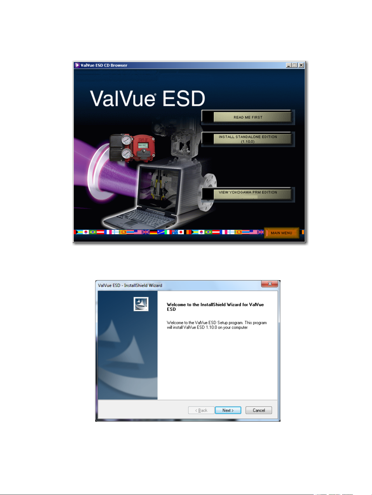
2. Select INSTALL SOFTWARE and a screen appears (Figure 2).
Figure 2 Software Choice
3. Click INSTALL STANDALONE VERSION and an installShield screen appears (Figure 3).
Figure 3 Install Shield Wizard
24 | =GE Oil & Gas
© 2014 General Electric Company. All rights reserved.
Page 25
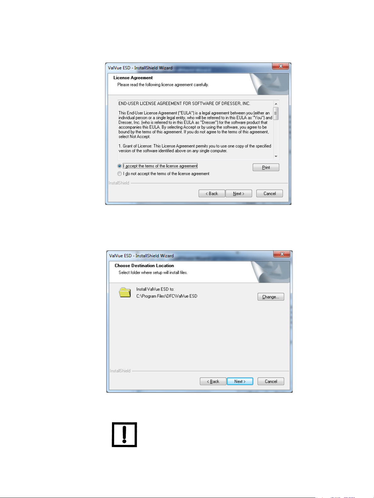
4. Click Next and the License Agreement screen appears (Figure 4).
Figure 4 License Agreement
5. Click the accept radio button, click Next and the Choose Destination Location screen appears (Figure 5).
Figure 5 Choose Destination Location
NOTE Click Change to open the Choose Folder screen to navigate to and
© 2014 General Electric Company. All rights reserved.
designate a non-default folder.
Masoneilan Valves ValVue ESD Instruction Manual =| 25
Page 26
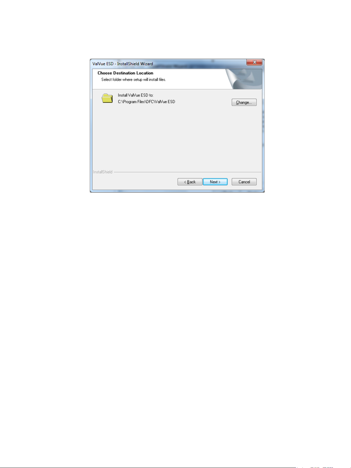
6. Click Next and a screen appears (Figure 6).
Figure 6 Ready to Install
7. Click Install and the Setup Status screen appears followed by InstallShield Wizard Complete.
8. Click Finish.
26 | =GE Oil & Gas
© 2014 General Electric Company. All rights reserved.
Page 27
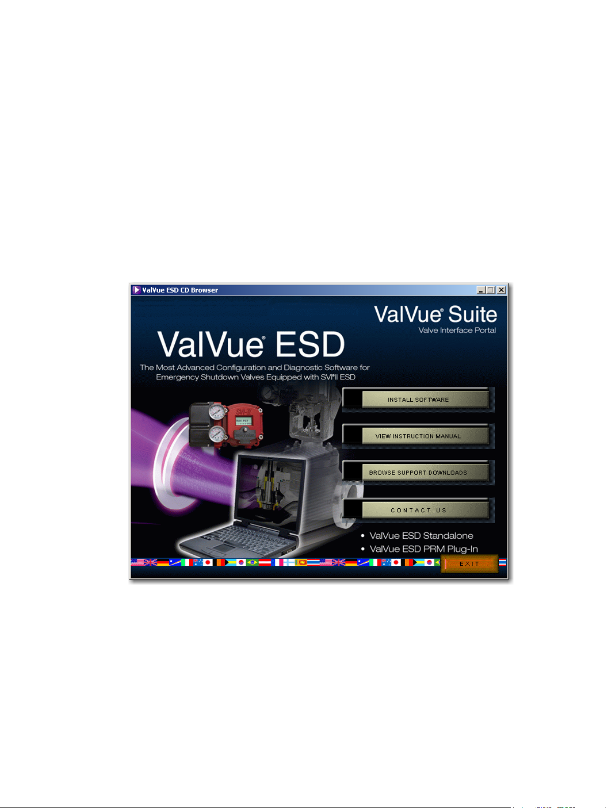
Installing the Yokogawa PRM Plug-In
This process consists of:
“Installing Central Server”
or
“Installing Plug-In Client” on page 33
Installing Central Server
This installs both the plug-in and the central database.
To install the software:
1. Insert the CD into computer CD drive and the CD browser launches (Figure 7).
Figure 7 ValVue ESD CD Browser
© 2014 General Electric Company. All rights reserved.
Masoneilan Valves ValVue ESD Instruction Manual =| 27
Page 28
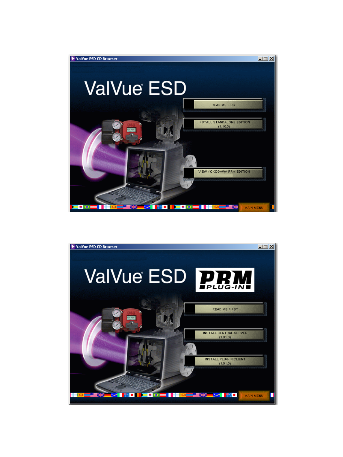
2. Select INSTALL SOFTWARE and a screen appears (Figure 8).
Figure 8 Software Choice
3. Click VIEW YOKOGAWA PRM EDITION and a screen appears (Figure 9).
28 | =GE Oil & Gas
Figure 9 PRM Plug-In Main Screen
© 2014 General Electric Company. All rights reserved.
Page 29
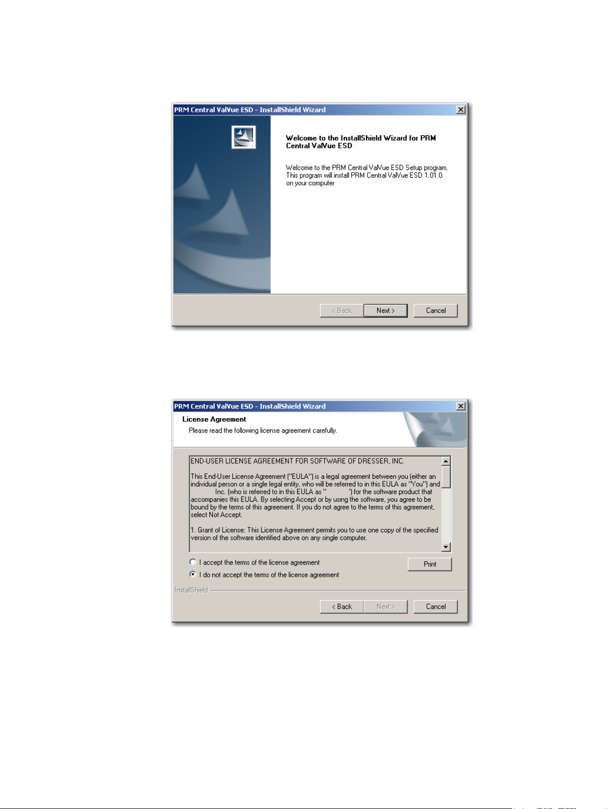
4. Click Install Central Server and a screen appears (Figure 10).
Figure 10 Install Shield Central Server
5. Click Next and the License Agreement screen appears (Figure 11).
Figure 11 PRM Central Server License Agreement
© 2014 General Electric Company. All rights reserved.
Masoneilan Valves ValVue ESD Instruction Manual =| 29
Page 30
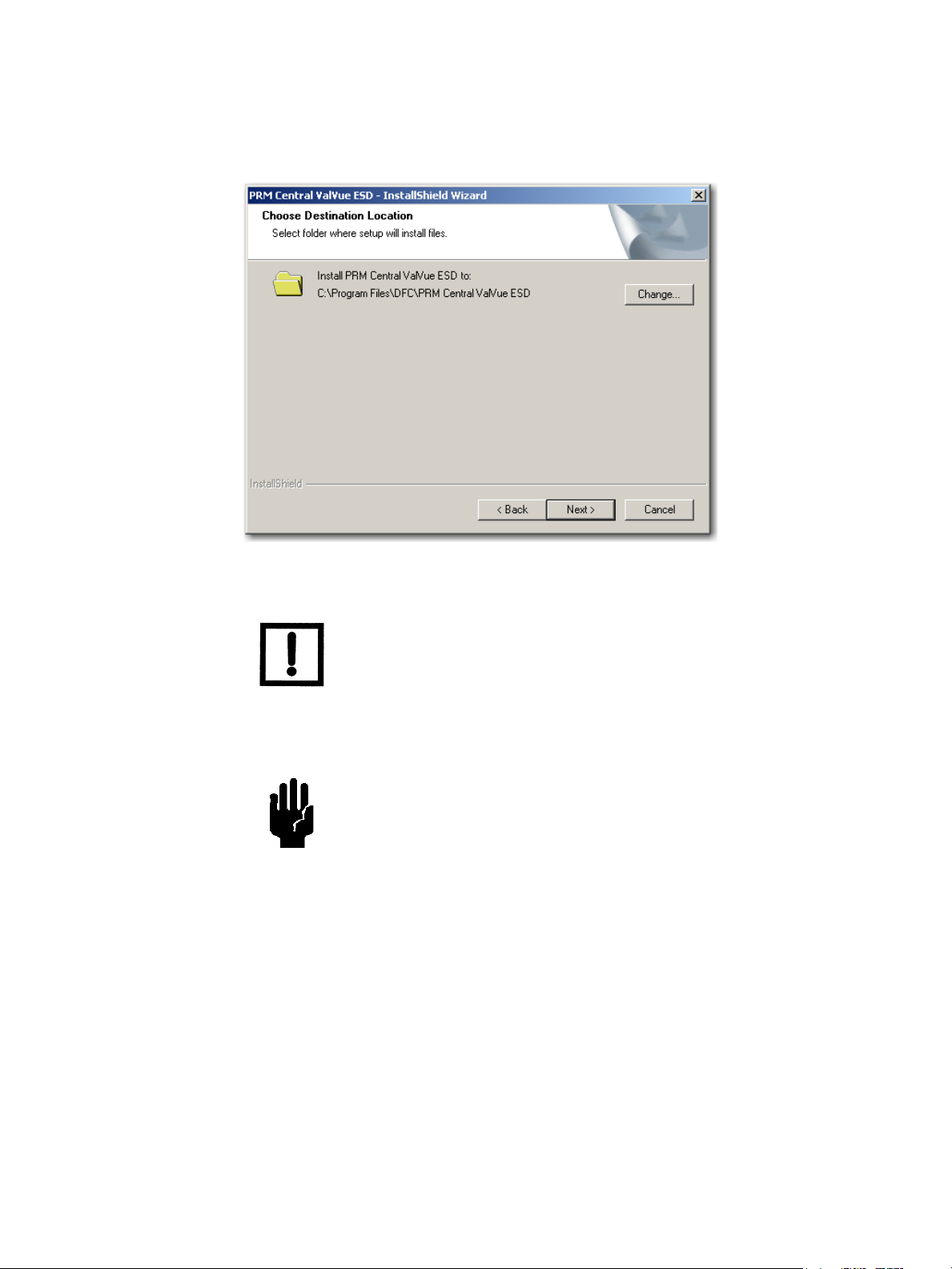
6. Click the accept radio button, click Next and the Choose Destination Location screen appears (Figure 12).
Figure 12 PRM Central Server Destination Folder
NOTE Click Change to open the Choose Folder screen to navigate to and
designate a non-default folder.
7. Click Next and the screen appears (Figure 13).
CAUTION Click Change to open the Choose Folder screen to navigate to and
designate a non-default folder. Make a note of this machine and
folder share name, ValVue ESD DATABASE as it is required when
installing the PRM PLUG-IN ValVue.The installer also creates a data
source for the database. If the database already exists, the
installer updates the tables as necessary. No existing data is lost.
30 | =GE Oil & Gas
© 2014 General Electric Company. All rights reserved.
Page 31
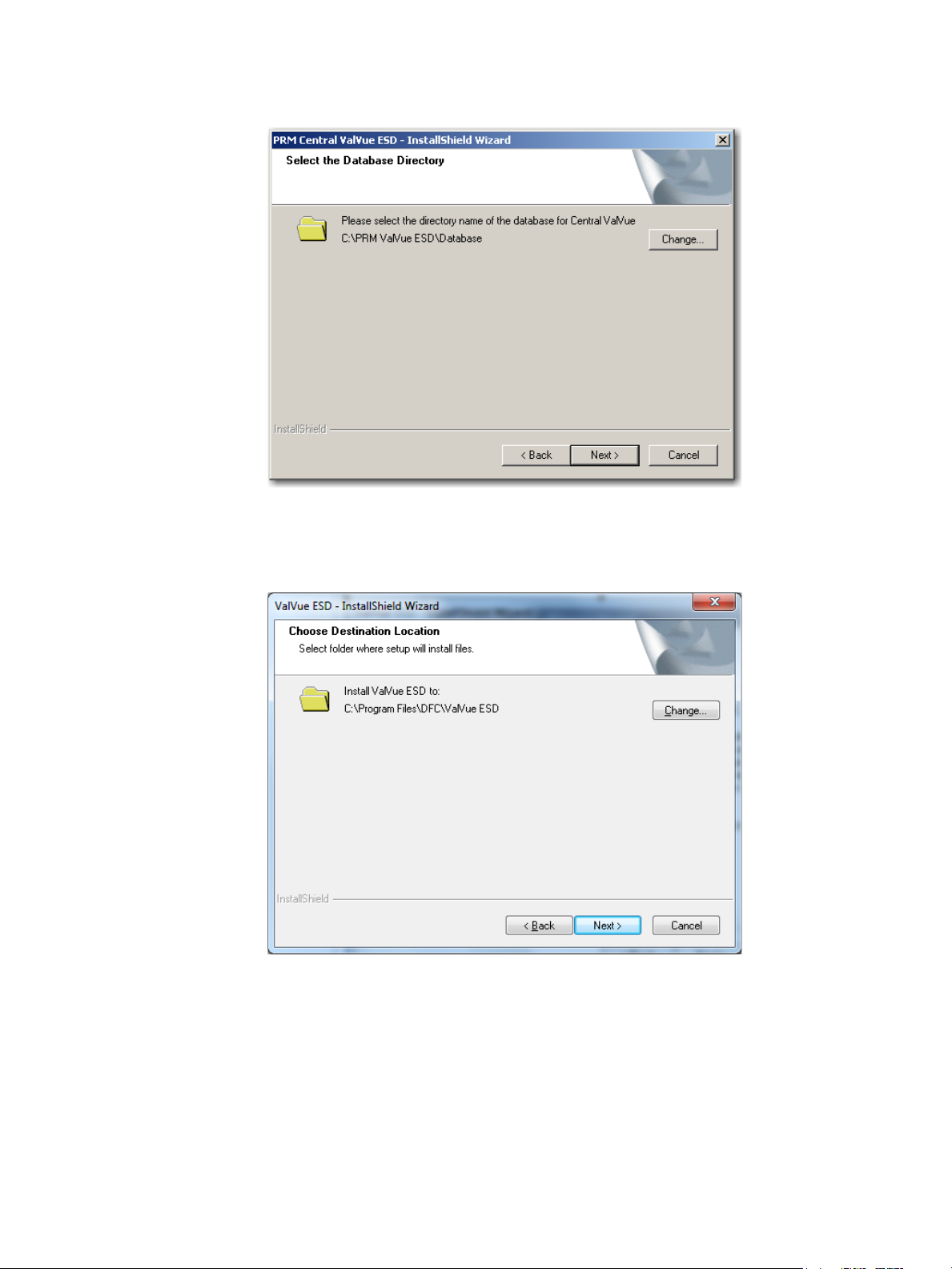
Figure 13 PRM Central Server Database Directory Destination Folder
8. Click Next and a screen appears (Figure 14).
9. Click Install and the Setup Status screen appears followed by InstallShield Wizard Complete.
10. Click Finish.
© 2014 General Electric Company. All rights reserved.
Figure 14 Ready to Install
Masoneilan Valves ValVue ESD Instruction Manual =| 31
Page 32

11. A Launch Service Install dialog appears; click OK and a dialog appears (Figure 15).
Figure 15 PRM Central Server Dialog
12. Click OK and another dialog appears (Figure 16).
Figure 16 PRM Central Server Dialog II
13. Click OK and another dialog appears (Figure 17).
Figure 17 PRM Central Server Dialog III
14. Click OK and another dialog appears (Figure 18).
Figure 18 Database Directory Reminder
15. Click OK.
32 | =GE Oil & Gas
© 2014 General Electric Company. All rights reserved.
Page 33

Installing Plug-In Client
This installs the plug-in and the client software and a database. Install this application on
every computer on which PRM Client is installed after PRM Central is installed for the
particular PRM server. This application does not require registration.
To install the software:
1. Insert the CD into computer CD drive and the CD browser launches (Figure 19).
Figure 19 ValVue ESD CD Browser
© 2014 General Electric Company. All rights reserved.
Masoneilan Valves ValVue ESD Instruction Manual =| 33
Page 34

2. Select INSTALL SOFTWARE and a screen appears (Figure 20).
Figure 20 Software Choice
3. Click VIEW YOKOGAWA PRM EDITION and a screen appears (Figure 21).
34 | =GE Oil & Gas
Figure 21 PRM Plug-In Main Screen
© 2014 General Electric Company. All rights reserved.
Page 35

4. Click Install Plug-in Client and a screen appears (Figure 22).
Figure 22 Install Shield PRM Plug-In
5. Click Next and the License Agreement screen appears (Figure 23).
Figure 23 PRM Plug-In License Agreement
© 2014 General Electric Company. All rights reserved.
Masoneilan Valves ValVue ESD Instruction Manual =| 35
Page 36
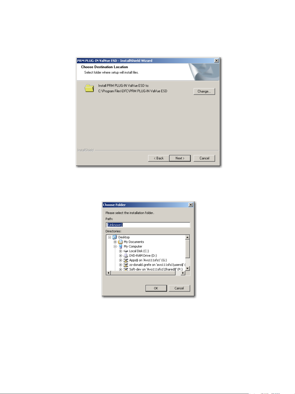
6. Click the accept radio button, click Next and the Choose Destination Location screen appears (Figure 24).
Figure 24 PRM Plug-In Destination Folder
7. Click Change and the Choose Folder dialog appears (Figure 25).
Figure 25 Choose Folder
36 | =GE Oil & Gas
© 2014 General Electric Company. All rights reserved.
Page 37

8. Navigate to the desired folder, click OK and Next and the screen appears (Figure 26).
CAUTION Use the same folder as with the ValVue ESD DATABASE.The
installer also creates a data source for the database. If the
database already exists, the installer updates the tables as
necessary. No existing data is lost.
Figure 26 PRM Plug-In Client Database Location Destination Folder
9. Click Change and the Choose Folder dialog appears (Figure 27).
Figure 27 Choose Folder
10. Navigate to the desired folder, click OK and Next and the screen appears (Figure 28).
© 2014 General Electric Company. All rights reserved.
Masoneilan Valves ValVue ESD Instruction Manual =| 37
Page 38

Figure 28 Ready to Install
11. Click Install and the Setup Status screen appears followed by InstallShield Wizard Complete.
12. Click Finish.
PRM PLUG-IN ValVue ESD Warning
Listed below are warnings pertaining to the installation of the PRM PLUG-IN ValVue ESD.
PRM Multi-Server
Because of the connection with the database and Central ValVue ESD, the Multi-Server
switching feature, available on the PRM client, is not allowed.
PRM PLUG-IN ValVue ESD Installation Folder
As mentioned in installation instructions, the PlugInValVue ESD application must be installed
to the same drive and folder on every machine
38 | =GE Oil & Gas
© 2014 General Electric Company. All rights reserved.
Page 39

Registering ValVue ESD
When you start ValVue ESD for the first time the registration window launches. ValVue ESD
software must be registered to activate the permanent installation. ValVue ESD can be used
without registration for 60 days. Registration allows the factory to keep track of all of ValVue
ESD users so that we can notify you of any changes or important information about new
software features and updates. A registration card is included with the installation CD.
The software package contains a serial number. Keep a record of the serial number in a
secure location. Do not discard the registration card. To register your software, you must
launch the ValVue to obtain an installation ID number, then contact the factory by mail,
telephone, email or Fax, and provide your name, company’s name, contact information, the
CD-ROM serial number, and the installation ID number from the ValVue ESD login display.
Contact information is provided on the registration card that is part of the software package.
Your serial number is located on the ValVue ESD package and on the enclosed sticker. Place
the serial number sticker on the detachable card included with the Registration Instruction
card and store the card in a secure location. You need the serial number to move ValVue ESD
to a different computer.
The Software Registration Center provides you with software keys that you enter the next
time you run the program. Contact the factory for a new software key if you are moving
ValVue ESD to a different computer or, if you do not have a serial number.
To register ValVue ESD:
1. Start ValVue ESD either by clicking on the desktop icon or using the Start programs selection. When you start ValVue ESD, the registration window appears (Figure 29).
Figure 29 Owner and Product Key Registration Window
© 2014 General Electric Company. All rights reserved.
Masoneilan Valves ValVue ESD Instruction Manual =| 39
Page 40

2. Enter Name, Company and Serial Number in the registration and click OK.
Figure 30 Applying Owner and Product Key Information
The software key registration window appears (Figure 31).
3. Click Mux and enter a software key for the Mux option, if applicable.
Figure 31 Software and Mux Key Window
40 | =GE Oil & Gas
© 2014 General Electric Company. All rights reserved.
Page 41

4. Click Registration (Figure 32).
Figure 32 Launching Registration Window
5. Enter your name and the name of your company. You are now ready to contact the factory with this information, to obtain your software keys. There are four methods shown on the Registration Instruction Card:
Phone
Fax
Figure 33 Registration Window
© 2014 General Electric Company. All rights reserved.
Masoneilan Valves ValVue ESD Instruction Manual =| 41
Page 42

6. Click Save to File to save your registration file. A Windows browser appears (Figure 34).
7. Navigate to the desired folder, name the registration information (.txt) file and click Save.
Figure 34 Save Registration Information
A dialog appears (Figure 35).
8. Email the registration information by clicking Yes.
42 | =GE Oil & Gas
Figure 35 Registration File Saved Dialog
ValVue ESD launches your email service and automatically attaches the registration and Masoneilan’s Software Registration Center.
9. Click Send to email the registration.
If your email program fails to start, contact the software registration center using the email address, phone number, address, or fax number given on the registration card (contained with the ValVue ESD cd).
A dialog indicating the email has been sent appears (Figure 36).
© 2014 General Electric Company. All rights reserved.
Page 43

10. Click OK to close the dialog.
Entering Software Keys
After you have sent the registration info, you are provided with software keys for ValVue ESD
and optional features (when applicable).
Once you have your key, to enable the program:
1. Start ValVue ESD.
2. Choose Help > View Registration.
3. Enter the Product Key (if not already entered).
Figure 36 Registration Email Sent Dialog
4. Click OK. On the 2nd registration screen, enter the software key returned by the factory (Figure 37).
Figure 37 Entering Software Key
5. Enter the software key, if applicable, by clicking on the screen under the Unlock Keys field and the field becomes active. Enter the Mux software key.
6. Click OK.
© 2014 General Electric Company. All rights reserved.
Masoneilan Valves ValVue ESD Instruction Manual =| 43
Page 44
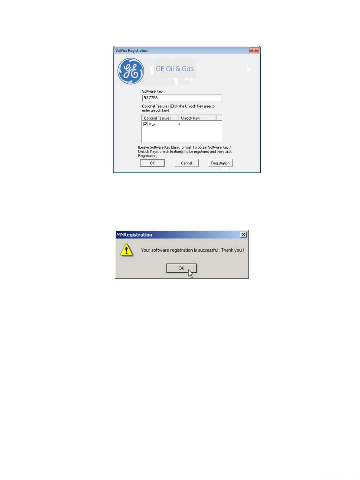
Figure 38 Entering Mux Unlock Key
When the registration is complete and successful the message shown in Figure 39 appears.
7. Click OK.
Figure 39 Successful Registration Message
44 | =GE Oil & Gas
© 2014 General Electric Company. All rights reserved.
Page 45

Licensing
In addition to registration, a license is required to test more than five devices.
To acquire a license for additional devices:
1. Select Help > Software License. The Software License menu item is enabled when the
2. Select the number of tags (devices) for which you would like licenses from the Number of
3. Click Generate File.
application is registered.
Tags drop down list.
Figure 40 Generating License File
© 2014 General Electric Company. All rights reserved.
Masoneilan Valves ValVue ESD Instruction Manual =| 45
Page 46

The ESD Licensing tool generates the licensing information file and opens a Windows browser with the file name.
Figure 41 Saving ESD Licensing Information File
4. Click Save.
A dialog appears (Figure 42) indicating the licensing file has been saved. If you have a valid email service you can email the file.
5. Click Yes to email the file.
Figure 42 ESD Licensing Information Email Dialog
46 | =GE Oil & Gas
© 2014 General Electric Company. All rights reserved.
Page 47

You receive a licensing file in response from the factory (Figure 43).
Activating the License
To activate the license:
1. Select Help > Software License and Figure 44 appears.
Figure 43 Licensing File
2. Click Load Licensing File. The software is licensed and the licensed number of tags appear at the top of the ESD Licensing tool and the number is greyed out in the Number of Tags drop down list.
© 2014 General Electric Company. All rights reserved.
Figure 44 Load Licensing File
Masoneilan Valves ValVue ESD Instruction Manual =| 47
Page 48

This page intentionally left blank.
Page 49

Getting Started
Main Window
After you have successfully started ValVue ESD the main window appears (Figure 45), divided
into two tabs:
Connected Devices - Lists all connected devices in the SIS found during initial scan or
re-scan.
Plant Schedule - Provides access to view the next scheduled PST, edit schedule and
synchronize devices
Each tab has an associated screen and functions. The Connected Devices screen appears on
startup and lists all scanned, available devices on the selected COM port. When Load Device List
from Database on Startup option is enabled (see “Using a Device List File” on page 60) ValVue
ESD does not re-scan the port.
Figure 45 ValVue ESD Main Window - Connected Devices
© 2014 General Electric Company. All rights reserved.
Masoneilan Valves ValVue ESD Instruction Manual =
| 49
Page 50

Connected Devices Icons
Disconnected Device Icon
When you start ValVue ESD the main window displays the scanned, connected devices and
may also display an icon (Figure 46), located to the left of the device name.
Figure 46 ValVue ESD Main Window with Disconnected Device Icon
There are four possible icons:
Connected - indicates that the device is connected to the SIS and is available for
running ValVue ESD.
Disconnected - indicates that the device is disconnected from the SIS and is only
available offline.
Status - indicates that there is more device status information available on the
Status screen.
Unlicensed - indicates that there is no ValVue ESD license available. In this case
you are not able to launch ValVue ESD for the selected device.
50 | =GE Oil & Gas
© 2014 General Electric Company. All rights reserved.
Page 51

Plant Schedule
When you select the Plant Schedule tab the Plant Schedule screen appears (Figure 47). The
Plant Schedule tab indicates when the last PST (Partial Stroke Test) was executed and when
the next PST is scheduled to occur. You can also edit the plant PST schedule, synchronize the
current device, synchronize all devices in the SIS (Safety Integrated System) and export all
schedule data to an Excel file.
Figure 47 Plant Schedule Screen
© 2014 General Electric Company. All rights reserved.
Masoneilan Valves ValVue ESD Instruction Manual =| 51
Page 52

Editing Plant Schedule
Use the Plant Schedule tab to edit the schedule for when PST (Partial Stroke Test) is executed
for the SIS (Safety Integrated System). You can edit the schedule for an individually selected
device or you can edit the PST schedule for all devices connected to the plant.
To edit the plant schedule for the entire plant:
1. Click Edit (Figure 48).
52 | =GE Oil & Gas
Figure 48 Accessing Edit Function
© 2014 General Electric Company. All rights reserved.
Page 53

2. Click Edit and enter the number in the Days field for the Plant Cycle (Figure 49).
Figure 49 Editing Plant Cycle PST
© 2014 General Electric Company. All rights reserved.
Masoneilan Valves ValVue ESD Instruction Manual =| 53
Page 54

3. Click Apply to save and apply changes (Figure 50).
Figure 50 Applying Edits to the Plant Schedule
A warning (Figure 51) asking you to confirm changes appears.
4. Click OK to save the schedule changes for all plant devices.
Figure 51 Changing Plant Schedule Warning
Editing Plant Schedule for a Selected Device
You can also edit the PST schedule for an individual, selected plant device:
1. Click Edit (Figure 48).
2. Click Edit and change the number in the Days field for the Plant Cycle (Figure 49).
54 | =GE Oil & Gas
© 2014 General Electric Company. All rights reserved.
Page 55

3. Select the device for schedule update by clicking on the device name.
4. Click Set PST Schedule (Figure 52).
Figure 52 Setting PST Schedule for Individual Device
A warning (Figure 53) appears.
5. Click OK to close the dialog and return to the Plant Schedule screen.
Figure 53 Plant Schedule Set for Individual Device
© 2014 General Electric Company. All rights reserved.
Masoneilan Valves ValVue ESD Instruction Manual =| 55
Page 56

Export to Excel
You can save or create a comma separated value file (.csv) of the Plant Schedule data and
export the file to Excel. With the Excel file you can perform schedule analysis and export the
data to other formats. To export a plant schedule to Excel:
Click Export to Excel (Figure 54).
ESDVue launches Microsoft Excel and displays the plant schedule data, as Excel values.
Connected Devices Help
Launch Help from the Connected Devices screen, either by clicking Help at the bottom right
corner of the screen, or by selecting Help from the Help menu and help appears starting at the
Connected Devices content.
56 | =GE Oil & Gas
Figure 54 Selecting Export to Excel
© 2014 General Electric Company. All rights reserved.
Page 57

Connected Devices Tools Menu
Use the Tools menu (Figure 55) to access the tools to set up the selected device for operation.
See also “Configuring ValVue ESD Options” on page 58 and “Multiplexor Setup and
Operation” on page 62.
Figure 55 Accessing Connected Devices Tools Menu
© 2014 General Electric Company. All rights reserved.
Masoneilan Valves ValVue ESD Instruction Manual =| 57
Page 58

Configuring ValVue ESD Options
Launching Set Options
1. Right-click to open the context menu (Figure 56) and select Set Options to open the
Options dialog.
Set Options Screen
Use the Set Options screen (Figure 57) to set communication parameters for the SVI II ESD.
The following options are available:
Interval Between Cycles - time between patrolling cycles
Interval Between Devices - time between each device within a cycle
Load Device List from Database on Startup - allows loading of saved device addresses
Com Port - select Communications Port
Hart Option - enable/disable Multidrop feature
58 | =GE Oil & Gas
Figure 56 Launching Set Options
and information
© 2014 General Electric Company. All rights reserved.
Page 59

Master Mode - select Primary or Secondary Master
Use Multiplexor - enable/disable Multiplexor feature
OK - saves changes and opens the Connected Devices screen
Cancel - cancels any changes you have made to the Options parameters and opens
the Connected Devices screen
Figure 57 ValVue ESD Set Options Screen
Interval Between Cycles Patrolling is the time at which ValVue ESD searches for connected
devices. ValVue ESD searches through all connected devices. Each
time a search through all connected devices is executed is considered a cycle. You can set the interval time between cycles; i.e. when
one patrolling cycle has been completed how long ValVue ESD waits
to start another patrolling cycle. To change the interval between
patrolling cycles click in the field and change the number (in seconds).
Interval Between Devices Patrolling is the time at which ValVue ESD searches for connected
devices. ValVue ESD searches through all connected devices. Each
time a search through all connected devices is executed is considered a cycle. You can set the patrolling interval time between
devices within a cycle; i.e. when one device has been recognized
how long ValVue ESD waits to patrol for the next device. To change
the patrolling interval between devices click in the field and change
the number (in seconds).
© 2014 General Electric Company. All rights reserved.
Masoneilan Valves ValVue ESD Instruction Manual =| 59
Page 60

Using a Device List File The device list can be saved in a file to eliminate rescanning each
time Connect is selected. This is useful only with multiplexors. Unless
Load Device List from Database on Startup is selected as an option,
the device addresses file used is temporary and is rescanned each
time the program is restarted. If selected, you can select a file to
save the device list. This file is read when the program is started and
the list displayed. Select New File to change the file or create a new
one.
Com Port Selection Select the COM Port on your PC that is connected to the HART
modem. If you’re not sure about the COM port the modem is connected to, go to the Windows Device Manager to locate the Com
Port number assigned to the PC.
Multidrop When more than one device is connected to a loop or if polling
addresses other than 0 have been assigned to devices, select Allow
Multidrop. ValVue ESD supports HART devices, including SVI and SVI
II, SVI II ESDs, and HDLTs with non-zero polling addresses and supports multiple SVI and SVI II and SVI II ESDs on the same loop for split
ranging, for example. If the box is unchecked, ValVue ESD looks for
devices only at polling address 0. When in multidrop mode, even if a
device is found at polling address 0, ValVue ESD polls addresses up to
15.
Master Mode ValVue ESD can send commands to a HART device as a primary mas-
ter or as a secondary master. HART is a Master-Slave communication
protocol, where the slave (field device) replies to commands sent by
the master. The HART protocol allows for a device to communicate
simultaneously with two masters, as long as they are different Masters. One being a Primary Master and the other being a Secondary
Master. A Primary Master is defined as a host (or interface) which is
connected permanently with a slave, such as a control system. A
Secondary Master is a host (or interface) connected temporarily to
the slave (like a handheld or laptop computer) and that is not part of
the control system.
When used with a multiplexor, operation is allowed when a second
HART master, such as a DCS system, is communicating. The ValVue
ESD program must be configured to match the configuration of the
multiplexor. If the multiplexor is a primary master, ValVue ESD must
also be configured to be a primary master.
60 | =GE Oil & Gas
© 2014 General Electric Company. All rights reserved.
Page 61

Mux Option The Use Multiplexor option allows you to select multiplexor opera-
tion. If the Use Multiplexor control is checked then the MUX Setup,
and MUX reset controls are added to the Connected Devices page
context (right click) menu.
Check Use Multiplexor and set a baud rate that is equal to
the baud rate set on the multiplexor hardware with DIP
switches.
NOTE Settings in the Options page for ValVue ESD must agree with the
MUX configuration settings that are also shown. The Mux
configuration can have originated in other applications.
NOTE Do not check Use Multiplexor unless ValVue ESD is connected to
Multiplexor hardware.
The MTL multiplexor supports baud rates of 9600, 19200, and
38400. You must set a baud rate that matches the
configuration of the hardware.
After the options are selected, select OK to accept the
changes and exit to Connected Devices page or select
Cancel to discard the changes.
© 2014 General Electric Company. All rights reserved.
Masoneilan Valves ValVue ESD Instruction Manual =| 61
Page 62

Multiplexor Setup and Operation
ValVue ESD supports the MTL HART multiplexor allows you to monitor and operate many SVI II
ESD PST controllers from a single computer.
The MTL 4840 HART maintenance system is a widely used multiplexor for communicating with
HART instruments. Connected to a computer serial port with an RS232/RS485 converter, the
multiplexor is capable of supporting up to 31 nodes, each with the capability of supporting up
to 16 sub nodes. Each sub node can control 16 loops. Therefore, the multiplexor provides the
potential to communicate with a maximum of 7936 HART loops, i.e., 31 (nodes) x 16 (sub
nodes) x 16 (loops) using one computer interface. Additionally, the multiplexor supports the
multidrop connection of HART devices on a single loop. Therefore, using the multidrop feature
it is possible to expended capacity of a system beyond 7936 HART devices.
For more information regarding the MTL multiplexor, refer to the manufacturer’s documents.
Using the multiplexor capability of ValVue ESD and the MTL multiplexor, monitoring and
communicating with many SVI’s and other HART devices is possible. After start-up and login to
the ValVue ESD program, the Connected Devices screen appears and provides options to
setup the multiplexor.
Use of the optional multiplexor ValVue ESD software requires an additional license and
registration. Contact your local representative for licensing assistance. A 60 day trial of the
multiplexor option is provided without licensing.
Selecting Mux Setup
To select the Mux Setup function:
1. Check Use Multiplexor and select the baud rate and node in the ValVue ESD Set Options (see “Mux Option” on page 61) return to the Connected Devices page.
2. Right-click on the Connected Devices page and select Mux Setup (Figure 58).
62 | =GE Oil & Gas
© 2014 General Electric Company. All rights reserved.
Page 63
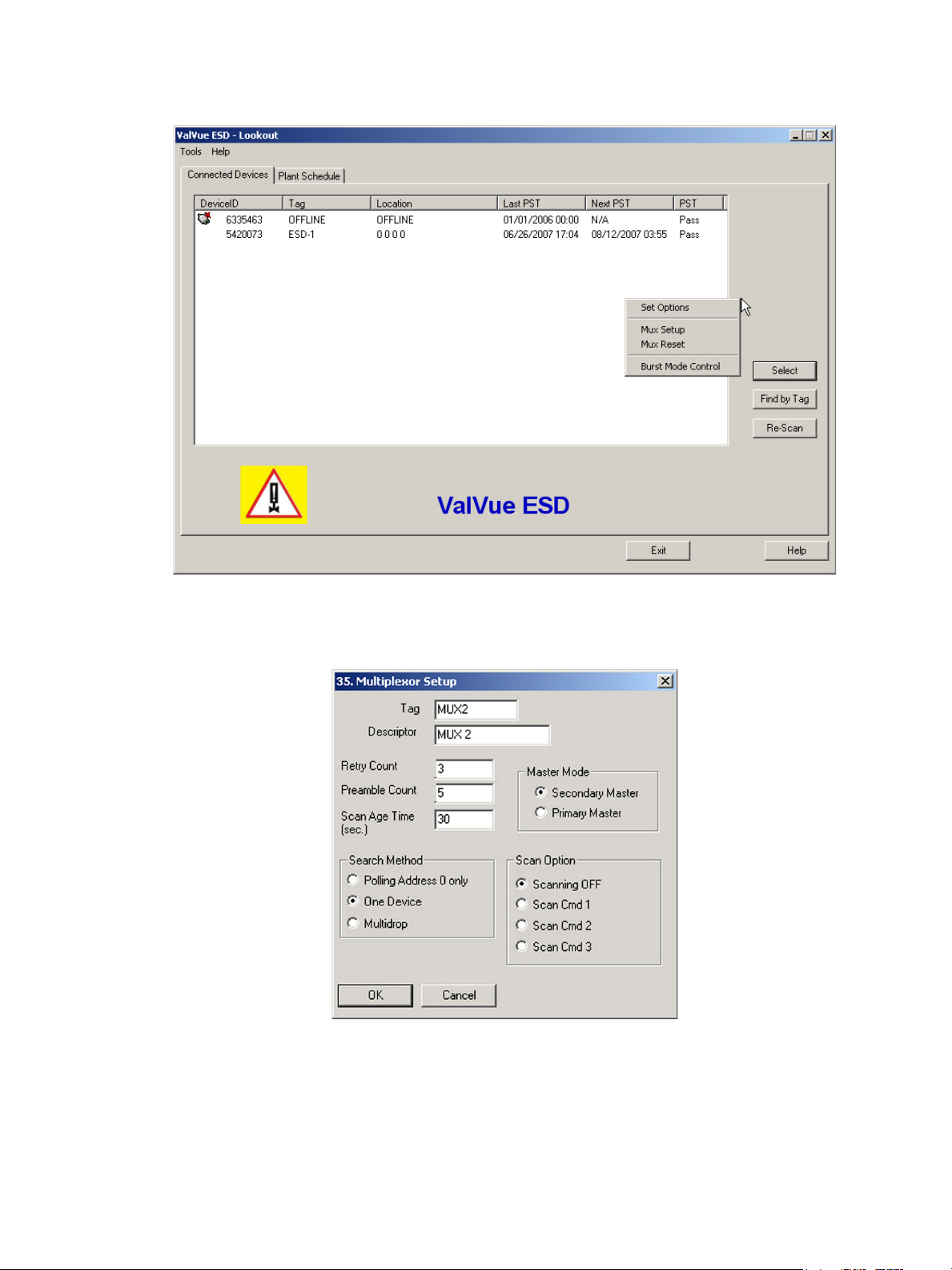
Figure 58 Context Menu with Mux Functions
The Multiplexor Setup window appears (Figure 59).
Figure 59 Multiplexor Setup
© 2014 General Electric Company. All rights reserved.
Masoneilan Valves ValVue ESD Instruction Manual =| 63
Page 64

Configuring the Multiplexor
1. Select MUX Setup from the context menu to setup the nodes used on the MTL multiplexor.
The Connected Devices page appears and prompts for the nodes to be configured.
2. Type a number between 1 and 31 for the desired node, e.g. 1 for node 1 and select OK. The node address must match the DIP switch setting on the MUX hardware.
The Multiplexor Setup dialog appears (Figure 59).
3. Set the Master Mode: Primary or Secondary Master.
NOTE ValVue ESD must be configured to be the same type of master as
The multidrop option substantially increases the time required to scan each node of the Mux.
Multiplexor Options Setup Dialog
Use this procedure to setup Multiplexor options.
1. Right-click in the Connected Devices page and select Set Options.
the multiplexor. Use both the Options setup and Mux setup
screens to check and compare the selection. Both can be primary
or both can be secondary.
2. Check the Use Multiplexor box on the Options page.
3. Select which communication serial port the computer uses for the HART communication channel. Once selected in the Options dialog, this selection overrides any selection on the command line that starts the program.
4. Select the baud rate to match that set with dip switches on the multiplexor hardware.
The device list is automatically saved to the device database. This file is read whenever the
program is started and the saved device list appears. This is particularly useful for a
multiplexor connected to many devices and saves the time required to re-scan.
Tag This is a user-entered value of up to 7 characters, used to identify the
MTL multiplexor node in the system. The tag appears in Device List
box in Connected Devices page.
Descriptor A description with up to 15 characters for the MTL multiplexor node.
Retry Count The number of times the multiplexor retries sending a command to a
Hart device before returning with an error. The valid range for this
number is 0 to 5. The recommended number is ‘3’.
64 | =GE Oil & Gas
© 2014 General Electric Company. All rights reserved.
Page 65

Preamble Count A device using the HART protocol sends a short string of characters
at the beginning of each communication to wake up the other
device. This string is called a preamble. The number of preambles
prefixed to each Hart command sent to a device varies from device
to device. The valid range is 2 to 20. Recommended values for this
parameter are 3 to 5 when using the Mux. ValVue ESD allows for a
user-configured Mux preamble count.
Scan Age Time The length of time in seconds that scan data remains valid. An error
is returned when the scan data requested is older than the time
when the data was last updated. This parameter set s this time for
other applications that use the multiplexor. ValVue ESD does not
support the scanning feature.
Multiplexor Master Mode ValVue ESD Options must be set to use the same mode as the multi-
plexor. Other applications that use the multiplexor or other HART
masters can require a special selection. See the multiplexor documentation for further information.
Search Method When building a device list, the multiplexor can use one of three
methods:
Polling Address 0 only - This method looks only at polling
address 0 for each loop. Any devices on a loop with a
non-zero polling address are not found.
Mux Reset
One Device - For each loop, all polling addresses are searched
until a device is found. The multiplexor does not continue the
search on a loop after the first device is found.
Multidrop - For each loop, polling address 0 is checked. If a
device is found, no further search is performed on that loop. If
no device is found at polling address 0, polling addresses 1 15 are searched and any devices found are added to the
device list.
Select Mux Reset to issue a reset command to a node of the multiplexor. This function is
enabled and used only in the multiplexor configuration of the program. You are prompted for
the node that is to be reset. When reset, the multiplexor node re-scans all of the devices
connected to it and depending on the multiplexor options set for the multiplexor, can take
some time to complete. If hardware has been added to the Mux or connected to different Mux
channels a rescan must be performed before the ValVue ESD re-scan can be used.
The Mux Reset is necessary when adding or removing HART devices on a Mux network. This
function updates the Mux’s Look Up Table utilized by ValVue ESD to map devices.
© 2014 General Electric Company. All rights reserved.
Masoneilan Valves ValVue ESD Instruction Manual =| 65
Page 66

Scan Option
The MTL multiplexor has the capability to continually scan the connected Hart devices to
report the results. ValVue ESD does not use this feature, but the option is provided to configure
the multiplexor as needed by other applications.
The multiplexor can be used to request information about HART devices. Select the MUX Reset
popup menu function to issue a reset command to a node of the multiplexor. You are
prompted for the node that is to be reset. When it is reset, the multiplexor node re-scans all of
the devices connected to the node (this hardware rescan is different from the re-scan done by
ValVue ESD from the Re-scan popup menu function). Depending upon the options set for the
multiplexor, this can take a while to complete. No communication can be done with devices on
the selected node until the reset is completed. After the reset is finished, select Re-scan popup
menu function to build a device list.
A device list is arranged in the order found on the multiplexor’s channels. This list can be very
long if there are many connected devices. To find a device by its tag, select the Find by Tag
button to open a text entry dialog. Enter a tag name to allow ValVue ESD to search the device
list for a device with a matching tag. If found, the device is selected and the window scrolled
so that its line is visible.
NOTE The Mux hardware re-scan is different from the re-scan performed
by ValVue ESD from the Re-scan button. No communication
between ValVue ESD and any device takes place on the node until
the reset is completed. This can take several minutes, depending
on MUX loading.
Selecting the Re-scan popup menu function causes ValVue ESD to build a new device list. All
nodes are checked. If there are a large number of devices connected to the multiplexor, this
function can take some time to complete. When the re-scan is completed, you can optionally
save the device list to a file so that rescanning is not necessary every time ValVue ESD is
started.
66 | =GE Oil & Gas
© 2014 General Electric Company. All rights reserved.
Page 67

Troubleshooting ValVue ESD Used with Mux
Table 3 lists some of the problems, causes, and corrective actions you may encounter when
setting up ValVue ESD used with a multiplexor (Mux).
Table 3 Troubleshooting ValVue ESD Used with Mux
Problem Cause Corrective Action
No devices found Both ValVue ESD and AMS are
connected to the Mux
The Mux is configured for AMS
communication
Baud rate setting does not
match setting
HART converter (RS-232 to
RS485) not working properly.
Expected device is not found in
Connected Devices list
Devices all have the same tag
name in Connected Devices
Mux Use Set Options in ValVue ESD to match the set-
Check for loose wires
Check for power cabling
between converter and Mux
Device was added after the
Mux performed its last scan
ValVue ESD and Mux are not
configured as the same type of
master
Connect ValVue ESD to the device with a
modem. If the installation is fundamentally safe
connect the input to the MTL 4046P Isolator. In a
general purpose system, connect directly to the
device wires.
Reconfigure the Mux for Cornerstone communications mode with MTL provided software.
ting in the Mux. Refer to the dip switch setting
on the MUX.
Check configuration of converter. Refer to the
manufacturer's instructions.
Click the Reset Mux button to update or power
off/on the Mux.
Set Mux and ValVue ESD so both are Primary
Master or both are Secondary Master.
© 2014 General Electric Company. All rights reserved.
Masoneilan Valves ValVue ESD Instruction Manual =| 67
Page 68

Configuring Burst Mode
The Burst Mode is a mode where the HART device continuously sends out data without being
polled for such data, by a Master. This mode is useful only for devices that are passive (i.e. not
a HART master), such as a HART to Analog converter (SPA from Moore Industries, Tri-Loop by
Rosemount). It is not necessary to set the burst mode to allow communications with a control
system since the control system is a master capable of polling the device. Turning on Burst
mode in cases where it is not required will affect the communication bandwidth.
Table 4 provides a summary of the data returned from the Burst mode (HART Command #3
equivalent to Process-Vars-Current).
Table 4 Burst Mode Data Return
Variable Description Units/Range
SVI II ESD (firmware 312)
PV (Primary Variable) Valve position 0-100%
SV (Secondary Variable) Actuator Net Pressure 0-150 psig
TV (Tertiary Variable) Not used (Future)
QV (Quaternary Variable) Not used (Future)
Use this procedure to configure a burst mode.
1. Select the intended device from the Connected Devices page.
2. Right-click on the gray background of the window to pop up a context menu.
3. Select the Burst Mode Control dialog.
4. Select the desired command.
5. Select OK.
NOTE When burst mode is enabled, ValVue ESD DOES NOT allow the
detailed device view to open communications to the device.
68 | =GE Oil & Gas
© 2014 General Electric Company. All rights reserved.
Page 69

Launching a Device
ValVue ESD opens the Connected Devices connection window (Figure 60), searches for
connected devices and lists those devices. To stop the searching process, select Stop. The list
includes offline device files and live devices. Scanning can take a few seconds if multidrop is
selected. When a Multiplexor is used, the process can take a longer time, depending upon
how many devices are connected.
The Connected Devices window is the interface tool for ValVue ESD and devices operating
ESDVue. Once a connected device has been selected and launched, ESDVue initiates the
selected device.
NOTE ValVue ESD is the main interface for connected devices. Once a
connected device is selected and launched the software tool for a
device is called ESDVue.
© 2014 General Electric Company. All rights reserved.
Figure 60 Connected Devices
Masoneilan Valves ValVue ESD Instruction Manual =| 69
Page 70

Offline Mode
There is on offline mode available in ValVue ESD to work with a disconnected Masoneilan
HART devices.
The offline options serve two purposes:
When SVI II ESD Offline is selected, you are prompted to select a dump file with a dp3
extension that contains configuration and calibration data used for running the SVI II ESD.
Viewing configuration, calibration and diagnostic data, for SVI II ESD using a dump file
(.dp3).
Learning the features and functions of both SVI II ESD and ValVue ESD when they are
not connected to an actual device.
70 | =GE Oil & Gas
© 2014 General Electric Company. All rights reserved.
Page 71

Selecting an Offline Device
After the initial device scan executed when you launch ValVue ESD, the Connected Devices
screen automatically appears and shows any devices found connected during the scan.
Notice in Figure 61 that the offline device was found.
To select and activate the device:
1. Either:
Click on the device name to highlight and then click on Select (Figure 61).
or
Double-click on the device name
Figure 61 Selecting an Offline Device
OR
Right-click on the device name and select Launching ESDVue (Figure 62).
© 2014 General Electric Company. All rights reserved.
Masoneilan Valves ValVue ESD Instruction Manual =| 71
Page 72

Figure 62 Right Clicking Offline Device
A file Open window appears (Figure 63).
2. Select a dump file as a simulated device. The dump files are installed with ValVue ESD in the same location as the program file: e.g. C:\Program Files\DFC\ValVue ESD/Data. The default location for SVI II ESD file Open window is shown in Figure 63.
Figure 63 File Open Window Launched at ValVue ESD
72 | =GE Oil & Gas
© 2014 General Electric Company. All rights reserved.
Page 73

3. Locate the Data folder in the ValVue ESD folder.
4. Locate the .dp3 in the Data folder (Figure 64) and click Open.
Figure 64 Offline dp3 Data File Default Location
The Monitor screen of the offline device appears (Figure 65).
Figure 65 Offline Device Displayed at Monitor Screen
© 2014 General Electric Company. All rights reserved.
Masoneilan Valves ValVue ESD Instruction Manual =| 73
Page 74

Selecting a Connected Device
After you have successfully logged into ValVue ESD the software automatically scans the SIS
(Safety Integrated System) for any devices that are connected to the system. The connected
devices that are found during the scan appear as shown in Figure 66.
To activate a connected device:
1. Click on the name of the device for activation (Figure 66).
2. Click Select.
ValVue ESD launches the selected device and the Monitor screen appears.
74 | =GE Oil & Gas
Figure 66 Selecting a Connected Device
© 2014 General Electric Company. All rights reserved.
Page 75

Device Information
When you start ValVue ESD the software scans all the devices connected to the controlling
computer. As ValVue ESD executes scanning the software also checks the status of each
connected device. The status information is shown when you click on the name of a device
and appears in a tool tip format (Figure 67).
Figure 67 Device Information Displayed
Find by Tag
To find a device by its tag name:
1. Select Find by Tag to open a text box.
2. Enter a tag name.
3. Select OK.
The software searches for a device with a matching tag. When found, the device is selected.
© 2014 General Electric Company. All rights reserved.
Masoneilan Valves ValVue ESD Instruction Manual =| 75
Page 76

Re-Scan
To build a new device list:
1. Select Re-Scan on the Connected Devices screen. In the:
Direct-connect configuration of ValVue ESD all polling addresses are checked if the
options allow multidrop.
Multiplexor configuration, all nodes are checked. If there are a large number of devices
connected to the multiplexor, this function takes time to complete.
The rescan is completes.
2. Save the device list to a file so that rescanning is not necessary every time ValVue ESD is started. If there is only one device on the loop, select Stop when it has been found to save scan time.
76 | =GE Oil & Gas
© 2014 General Electric Company. All rights reserved.
Page 77

Right Clicking on Device Name
When you right-click on a connected device name on the main ValVue ESD screen (Figure 68),
you can perform several functions particular to the selected device:
Launching ESDVue - launches ValVue ESD
Historical View - launches a historical performance view of the selected device
View Latest PST - launches the graph representing the most recent PST (Partial Stroke
Testing) of the selected device
Figure 68 Right Clicking on Connected Device
Launching ValVue ESD
There are three ways to launch ValVue ESD:
Right-click on the device name (in the list of connected devices) from the main ValVue
ESD screen.
Select the device on the ValVue ESD main screen and then click Select at the bottom
right of the screen.
Double-click the device name on the main screen.
© 2014 General Electric Company. All rights reserved.
Masoneilan Valves ValVue ESD Instruction Manual =| 77
Page 78

Launching Historical View
To launch this:
1. Right-click the device name in the Connected Devices tab.
2. Select Historical View and the PST Historical View window appears (Figure 69).
3. Select the Device ID from the drop down list.
4. Select the Start and End Dates for the PST data to view.
Changing the Historical View Start and End Dates
The Historical View start and end date field is set up as mm/dd/yyyy. There are two methods
for changing the PST schedule date field. You can click on each parameter of the date field;
i.e. mm, or dd, or yyyy, and change each individual parameter or you access the calendar in
the drop down of the date field.
To change the start date schedule for the next PST:
1. Click in each parameter (mm-dd-yy-hh-mm) of the date field and highlight the text.
2. Either:
Type over the old value with the new value for each parameter.
OR
a. Click in the drop down, located at the right of PST schedule date field and access the
date calendar (Figure 69).
b. Using the arrow key on the calendar, change the month, if necessary and drag the
mouse and select the correct date within the month by clicking on it.
78 | =GE Oil & Gas
© 2014 General Electric Company. All rights reserved.
Page 79

Figure 69 Selecting the Historical View Start Date
3. Select the End Date in the same manner as the Start Date.
ValVue ESD displays the historical PST data for the selected date range.
4. Select the parameter to view by clicking on the radio button to the left of the parameter name.
© 2014 General Electric Company. All rights reserved.
Masoneilan Valves ValVue ESD Instruction Manual =| 79
Page 80

View latest PST
To view the latest PST:
1. Right-click the device name in the Connected Devices tab
2. Select View Latest PST. ValVue ESD launches the latest PST Diagnostic graph.
For information on the Diagnostic Graph features, see PST Diagnostic Graph.
Figure 70 PST Historical View - Friction Displayed
Click Close and the latest PST Diagnostic Graph closes and the Connected Devices tab
appears.
80 | =GE Oil & Gas
© 2014 General Electric Company. All rights reserved.
Page 81

ESDVue's Work Environment
NOTE
Overview
After you have selected the connected device ValVue ESD launches and the device appears in
the first ESDVue Monitor screen (Figure 71). ESDVue is a series of tabs, with each tab named
according to their function.
ValVue ESD is the main interface for connected devices. Once a connected
device is selected and launched the software tool for a device is called ESDVue.
Figure 71 ESDVue Environment
© 2014 General Electric Company. All rights reserved.
Masoneilan Valves ValVue ESD Instruction Manual =
| 81
Page 82

Working in ESDVue
ESDVue is set up as a typical Windows program, with tabs, menus, dialogs, windows and
toolbars. After logging into ValVue ESD the currently selected device appears in ESDVue’s
Monitor screen. You can either perform operations on the Monitor screen or select another tab
to display another ESDVue screen.
Toolbar
The toolbar at the top of every ESDVue screen has two menu items: Tools and Help.
Modes of Operation
The SVI II ESD has three modes of operation:
“Normal Operation”
“Manual Operation ”
“Setup”
Normal Operation
In Normal mode, the SVI II ESD responds to the input signal and positions the ESD valve
accordingly.
In configurations where the safety function is triggered by current, when the input signal
current:
Falls below 5.6mA, the SVI II ESD de-energizes the ESD valve.
Rises above 14mA, the SVI II ESD energizes the ESD valve.
In configurations where the safety function is triggered by a discrete 0 - 24Vdc signal, when
the input signal voltage falls:
Falls below 3V, the SVI II ESD de-energizes the ESD valve.
Rises above 18V, the SVI II ESD energizes the ESD valve.
Manual Operation
In Manual mode, the valve does not respond to the input signal. Instead it remains stable in
one position, which is the position that the valve was in when manual mode was entered or a
new position selected using the HART or pushbutton interface. However, the Shutdown
function is activated if the signal is less than 5.6 mA (ASD) or 3 Vdc (A/DSD and DSD).
Setup
In the Setup mode, you can set calibration and configuration parameters. Additionally, you
can run response time tests, step response tests, and valve signatures.
82 | =GE Oil & Gas
© 2014 General Electric Company. All rights reserved.
Page 83

Device Trip
However, if a process was running at the onset of the trip condition, the valve may also go to
where it was before the process started, or stay at the de-energized stop. This is not true for
Normal mode.
In failsafe and low power the valve must stay at the de-energized stop.
Change Mode
Use the Change Mode button on all ESDVue screens to change the operating SVI II ESD mode.
When selected, you can change the SVI II ESD mode to any of three operating modes:
NOTE If the device is tripped, in Normal, Manual and Setup modes the
setpoint and the control mode are not affected by a device trip,
and as soon as the trip condition is removed (which includes Latch
if configured) the valve goes back to the state prior to the trip.
Normal - In this mode the SVI II ESD responds to the input signal and positions the
valve accordingly (indicator green).
Manual - in this mode the valve does not respond to the input signal. Instead it remains
stable in one position which is the position that the valve was in when manual mode
was entered or a new position selected by you (by changing the setpoint in the Monitor
screen).
Setup - In this mode you can set calibration and configuration parameters.
Additionally, you can run response time tests, step response tests, and PST controller
signatures (indicator yellow).
Whenever you leave the Normal mode, a warning appears (Figure 72).
1. Click OK to continue the mode change.
Figure 72 Leaving Normal Mode Warning
Whenever you return to Normal mode, a warning appears (Figure 73).
2. Click OK to continue the mode change.
© 2014 General Electric Company. All rights reserved.
Masoneilan Valves ValVue ESD Instruction Manual =| 83
Page 84

Exit
Clicking Exit quits the program.
ESDVue Help
Help is readily available from anywhere within ESDVue, including:
Main Help menu – available by clicking Help, located at the bottom, right corner of
Context Sensitive Help – available by right-clicking within the screen area
Toolbar Help - located in the toolbar at the top of every screen, available by clicking
Help Menu
The Help menu is the same on every screen and contains:
Help – launches the help file table of contents
Figure 73 Entering Normal Mode Warning
every screen
Help at the top of the screen.
84 | =GE Oil & Gas
Firmware Info – displays information about the firmware loaded into the SVI II ESD
About – displays information about ESDVue
© 2014 General Electric Company. All rights reserved.
Page 85

ESDVue Screens
Monitor Screen
From the Monitor screen (Figure 74), you can view the basic functions of the SVI II ESD
including tag and identification, input signal, setpoint, position, and status. You can also
change the SVI II ESD mode of operation and perform setup and command functions.
© 2014 General Electric Company. All rights reserved.
Figure 74 Monitor Screen
Masoneilan Valves ValVue ESD Instruction Manual =| 85
Page 86

Trend Screen
From the Trend screen (Figure 75) you can observe the performance of the valve in real time.
86 | =GE Oil & Gas
Figure 75 Trend Screen
© 2014 General Electric Company. All rights reserved.
Page 87

Configure Screen
The Configure screen (Figure 76) displays the current configuration parameters and provides
the ability to change them.
© 2014 General Electric Company. All rights reserved.
Figure 76 Configure Screen
Masoneilan Valves ValVue ESD Instruction Manual =| 87
Page 88

Calibrate Screen
The Calibrate screen (Figure 77) displays the current PST controller’s calibration parameters
and provides the ability to adjust them in the Setup mode.
88 | =GE Oil & Gas
Figure 77 Calibrate Screen
© 2014 General Electric Company. All rights reserved.
Page 89

Diagnostics Screen
The Diagnostics screen (Figure 78) provides the ability to functionally test operation of SVI II
ESD.
Figure 78 Diagnostics Screen
© 2014 General Electric Company. All rights reserved.
Masoneilan Valves ValVue ESD Instruction Manual =| 89
Page 90

PST
The PST (Partial Stroke Test) screen (Figure 79) provides access to Partial Stroke Testing.
90 | =GE Oil & Gas
Figure 79 PST Screen
© 2014 General Electric Company. All rights reserved.
Page 91

Status Screen
Use the Status screen (Figure 80) to see the operating and internal status of the SVI II ESD.
© 2014 General Electric Company. All rights reserved.
Figure 80 Status Screen
Masoneilan Valves ValVue ESD Instruction Manual =| 91
Page 92

Check
Use the Check screen (Figure 81) to set some of the basic parameters. This screen is used
primarily for troubleshooting.
92 | =GE Oil & Gas
Figure 81 Check Screen
© 2014 General Electric Company. All rights reserved.
Page 93

Monitor
What You Can Do on the Monitor Screen
The Monitor screen (Figure 82) is the first window displayed on starting ESDVue. You can:
Monitor the current operation of the SVI II ESD
Change operation parameters
Monitor the current PST controller Characteristics
Adjust the PST controller Indicator (graphical representation)
Generate reports on SVI II ESD operation
© 2014 General Electric Company. All rights reserved.
Figure 82 Monitor Screen
Masoneilan Valves ValVue ESD Instruction Manual =
| 93
Page 94

PST Controller Characteristics
The PST controller Characteristics displayed on the Monitor screen consist of:
Signal (mA) - Indicates the input analog signal expressed in mA.
Position (%) - Indicates the actual valve position in % of valve opening. 0% is always
closed and 100% is open.
Pressure (pressure units) - The SVI II ESD continuously monitors the actuator pressure.
It is displayed according to the configured units (psi, bar, or kpa).
I/P Current - the current in mA generated by the I/P.
Pressure1 (pressure units) - Actuator pressure when Single Acting.
Pressure2 (pressure units) - Has no value when Single Acting.
Supply (pressure units) - Pressure generated by the air supply.
Pilot Pres (pressure units) - pressure generated by the I/P.
Pressure, Pressure1 and Pressure2
If your unit is single acting, Pressure and Pressure1 both have the same value, the actuator
pressure.
Position Indicator
The Position Indicator shows the valve position graphically. The indicator consists of three
parts:
The upper part contains an indicator showing the value of the input signal. In Normal
The center green bar shows the valve position where % = Valve Open. The numerical
The lower part contains an indicator (thumb) showing the valve setpoint. In operating
Signal
mode this is the position setpoint.
WARNING If operating in manual mode, this is the position that the valve
moves to if returning operation to normal mode.
valve position is shown in the center.
mode, this is the same as the signal. In manual mode it is the valve setpoint. You can
drag the thumb to change the valve setpoint. While dragging, the number in the center
bar shows the manual setpoint for use when you release the thumb.
94 | =GE Oil & Gas
Indicates the input analog signal expressed in % of the configured signal range.
© 2014 General Electric Company. All rights reserved.
Page 95

Position
Setpoint
Indicates the actual valve position in % of valve opening. 0% is always closed and 100% is
open. Because the travel of a valve may exceed its nominal travel, positions greater than
100% are possible.
In NORMAL mode, the setpoint is the target position based on the characterized input. In
MANUAL mode, it is the target position to which the SVI II ESD is controlling the valve. Change
the manual setpoint by dragging the lower thumb on the position indicator.
© 2014 General Electric Company. All rights reserved.
Masoneilan Valves ValVue ESD Instruction Manual =| 95
Page 96

Changing the Setpoint
Prior to changing the position indicator ESDVue must be in Manual mode; click on Change
Mode and select Manual. There are three ways to change the position indicator:
Entering the setpoint value in the Setpoint dialog.
Dragging the position indicator.
Left-clicking on either side of the position indicator modifies the setpoint by 5%.
96 | =GE Oil & Gas
Figure 83 Position Indicator Active
© 2014 General Electric Company. All rights reserved.
Page 97

Entering Setpoint Value
To enter a value for the position indicator setpoint:
1. Right-click inside the position indicator area.
A dialog appears (Figure 84).
2. Enter the setpoint percentage and click OK.
Figure 84 Setpoint Dialog
© 2014 General Electric Company. All rights reserved.
Masoneilan Valves ValVue ESD Instruction Manual =| 97
Page 98

Status on the Monitor Screen
The SVI II ESD tracks operation and provides several health indicators. When there is a fault
code available in the SVI II ESD, this box contains (Figure 85) Additional Status Available. The
fault codes can be retrieved by:
1. Clicking the Check tab.
2. Selecting Read Status from the Send Command drop down list.
3. Clicking Send.
The status block also contains other status codes returned by HART. These include
Configuration Changed, Device malfunction, and Variable out of limits.
98 | =GE Oil & Gas
Figure 85 Monitor Screen - Additional Status Available
© 2014 General Electric Company. All rights reserved.
Page 99

Tag Information
The Tag Information on the Monitor screen displays the following items:
Tag
Descriptor
Message
Date
Assembly Number
This data appears at the same location on the Monitor, Configure and Calibrate screens but
can only be changed on the Configure screen (See “Changing Tag Information” on page 124).
PST/ESD Information
The Monitor screen contains status information on SVI II ESD's Partial Stroke Testing (PST) and
on the Emergency Shutdown Device (ESD) function. The PST/ ESD status fields are:
New PST - indicates when a new PST has been executed
New ESD Event - indicates whether there is a new ESD status event
PST in Progress - indicates whether a PST is in progress or not
ESD Tripped - indicates whether the Safety function has been tripped or not
ESD Type - indicates the type of SVI II ESD device: ASD, DSD, A/DSD - See “ESD Types”
on page 100.
Device Busy
Communication/No Communication - indicates if the SVI II ESD is in communication
with the Safety System
If the Status field is colored red, that status field is current.
© 2014 General Electric Company. All rights reserved.
Masoneilan Valves ValVue ESD Instruction Manual =| 99
Page 100

ESD Types
There are three configurations of the SVI II ESD available:
ASD 2-wire Analog Trip - Single pair of 4-20 mA twisted pair signal cable
DSD 2-wire Discrete Trip - Single pair of 0/24 VDC cable installation, with
A/DSD 4-wire Discrete Trip - Single pair of 4-20 mA twisted pair signal cable
installation, with superimposed HART communication. Connected to
Safety System AO card.
superimposed HART communication. Connected to Safety System
DO card.
installation, with superimposed HART communication. Connected to
Safety or Control System AO card.
AND
Single pair of 0/24 VDC cable installation. Connected to Safety System DO card.
100 | =GE Oil & Gas
© 2014 General Electric Company. All rights reserved.
 Loading...