

Page 1

GE Healthcare
TONOPORT V
Ambulatory Blood Pressure System
Firmware Version 2.1
Operator’s Manual
2001589-085 ENG Revision F
Page 2

Note
The information in this manual only applies to TONOPORT V, firmware version 2.1. It does not apply to earlier
firmware versions.
Due to continuing product innovation, specifications in this manual are subject to change without notice.
CASE™ is a trademark owned by GE Medical Systems Information Technologies GmbH, a General Electric
Company going to market as GE Healthcare.
© 2009–2016 General Electric Company. All rights reserved.
2 TONOPORT V 2001589-085 Revision F
Page 3

Contents
1 Application, Safety Information 6
2 Controls and Indicators 10
3 Setup 12
4 Application 17
5 Data Output 21
6 Error Codes 22
7 Software Installation 23
8 Cleaning, Maintenance, Disposal 25
9 Technical Specifications 27
10 Order Information 28
11 Appendix - Electromagnetic Compatibility (EMC) 29
Revision History
This manual is subject to the GE Healthcare change order service. The revision code, a letter that follows the
document part number, changes with every update of the manual.
Part No./Revision Date Comment
2001589-085 Revision A 2009-05 Initial release
2001589-085 Revision B 2010-04 General Information: modifications in 3rd
paragraph
Section 1.3: additional information concerning the
ingress of liquids
Chapter 2: four symbols added
Chapter 3: additional information concerning
alternative charger
2001589-085 Revision C 2011-10-31 CardioSys was removed globally
Chapters 1.1, 5 and 7: interface restrictions for
CASE/CardioSoft were added
Chapter 2: relevant battery charger symbols were
added
Chapter 7: CardioSoft version 6.7 for Windows 7
and reference to the “CASE-CS” folder were added
Chapter 9: measuring range for mean pressure was
corrected to '50 to 250 mmHg'
2001589-085 Revision D 2014-01-31 Changes on pages 4, 5, 11, 12, 23, and 24.
2001589-085 Revision E 2015-05-07 Changes on pages 8, 17, and 27.
2001589-085 Revision F 2016-07-12 Changes on pages 4, 11, and 28.
2001589-085 Revision F TONOPORT V 3
Page 4
General Information
General Information
The product TONOPORT V bears the CE marking
CE-0482 (notified body MEDCERT GmbH)
indicating its compliance with the provisions of the
Council Directive 93/42/EEC about medical devices
(including amendment 2007/47/EC) and fulfills the
essential requirements of Annex I of this directive. It
has an internal power source and is an MDD class IIa
device. The device fulfills the requirements of the
Directive 2011/65/EU of the European Parliament
and of the Council.
It has a type BF applied part.
The product fulfills the requirements of the standard
EN/IEC 60601-1 "Medical Electrical Equipment, Part
1: General Requirements for Basic Safety and
Essential Performance" as well as the electromagnetic
immunity requirements of the standard EN/IEC
60601-1-2 "Medical electrical equipment – Collateral
standard: Electromagnetic compatibility –
Requirements and tests" and applicable amendments.
The radio-interference emitted by this product is
within the limits specified in CISPR11/EN 55011,
class B.
The CE marking covers only the accessories listed in
the "Order Information" chapter.
This manual is an integral part of the equipment. It
should be available to the equipment operator at all
times. Close observance of the information given in
the manual is a prerequisite for proper equipment
performance and correct operation and ensures
patient and operator safety. Please note that
information pertinent to several chapters is given
only once. Therefore, carefully read the manual
once in its entirety.
This manual reflects the equipment specifications and
applicable safety standards valid at the time of
printing. All rights are reserved for devices, circuits,
techniques, software programs, and names appearing
in this manual.
On request GE Healthcare will provide a detailed
Service Manual.
The safety information given in this manual is
classified as follows:
Danger
indicates an imminent hazard. If not avoided, the
hazard will result in death or serious injury.
Warning
indicates a hazard. If not avoided, the hazard can
result in death or serious injury.
Caution
indicates a potential hazard. If not avoided, the
hazard may result in minor injury and/or product/
property damage.
To ensure patient safety and interference-free
operation and to guarantee the specified measuring
accuracy, we recommend only original equipment
accessories as available through GE Healthcare
distribution. The user is responsible for the
application of accessories from other manufacturers.
The symbol means: Consult accompanying
documents. It indicates points which are of particular
importance in the operation of the equipment.
4 TONOPORT V 2001589-085 Revision F
Page 5

PAR Medizintechnik GmbH & Co. KG
Sachsendamm 6
10829 Berlin
Germany
Tel. +49 30 235 07 00
Fax +49 30 213 85 42
Distributor:
GE Medical Systems
Information Technologies, Inc.
8200 West Tower Avenue
Milwaukee, WI 53223 USA
Tel: +1 414 355 5000
1 800 437 1171 (USA only)
1 800 668 0732 (Canada only)
Fax: +1 414 355 3790
General Information
The country of manufacture appears on the device label.
2001589-085 Revision F TONOPORT V 5
Page 6
Application, Safety Information
1 Application, Safety Information
1.1 Application
Intended Use
TONOPORT V is a small-size, patient-borne blood
pressure monitor for ambulatory, non-invasive
measurement of the patient’s blood pressure. If the blood
pressure cuffs listed in chapter 10 "Order Information" fit
the patient, it can be used on adults, children, and small
children. TONOPORT V is not suitable for blood
pressure measurements in neonates. Also it is not
suitable for use in intensive-care medicine.
For periods of up to 30 hours, TONOPORT V records the
patient's blood pressure at selectable intervals and saves the
results. There is a choice of three different measurement
protocols.
Biocompatibility
The parts of the equipment described in this
manual, including all accessories, that come in
contact with the patient during the intended use,
fulfill the biocompatibility requirements of the
applicable standards if used as intended. If you
have questions in this matter, please contact GE
Healthcare or its representatives.
Oscillometric Measuring Method
The blood pressure is measured by the oscillometric
method. The criteria for this method are the pressure
pulsations superimposed with every systole on the air
pressure in the cuff.
Using TONOPORT V with CASE™ / CardioSoft
TONOPORT V can be operated in conjunction with
CASE
™
(version 5.15 or later) or with the analysis
program CardioSoft (version 4.14 or later) that is
included with TONOPORT V. If the USB port is
used (CardioSoft only), it is necessary to install the
appropriate driver first (see “Software Installation”
on page 23). With these systems, individual
measurement protocols can be created and the
stored data can be reviewed on-screen in tabular
and graphic form. With V6.5 and subsequent
versions, the patient ID used by the analysis
program can be stored in TONOPORT V to allow
the collected data to be downloaded without
selecting the patient first (
Operator Manuals; you will find the CardioSoft
manual on the CardioSoft CD
refer to the respective
).
The blood pressure cuff is wrapped around the upper arm
and inflated to a pressure which must be clearly above the
expected systolic pressure. A pressure transducer mea-
sures the cuff pressure as well as the superimposed pres-
sure pulsations. During blood pressure measurements the
cuff must be level with the heart. If this is not ensured,
the hydrostatic pressure of the liquid column in the blood
vessels will lead to incorrect results.
When the patient is sitting or standing during
measurements, the cuff is automatically at the correct
level.
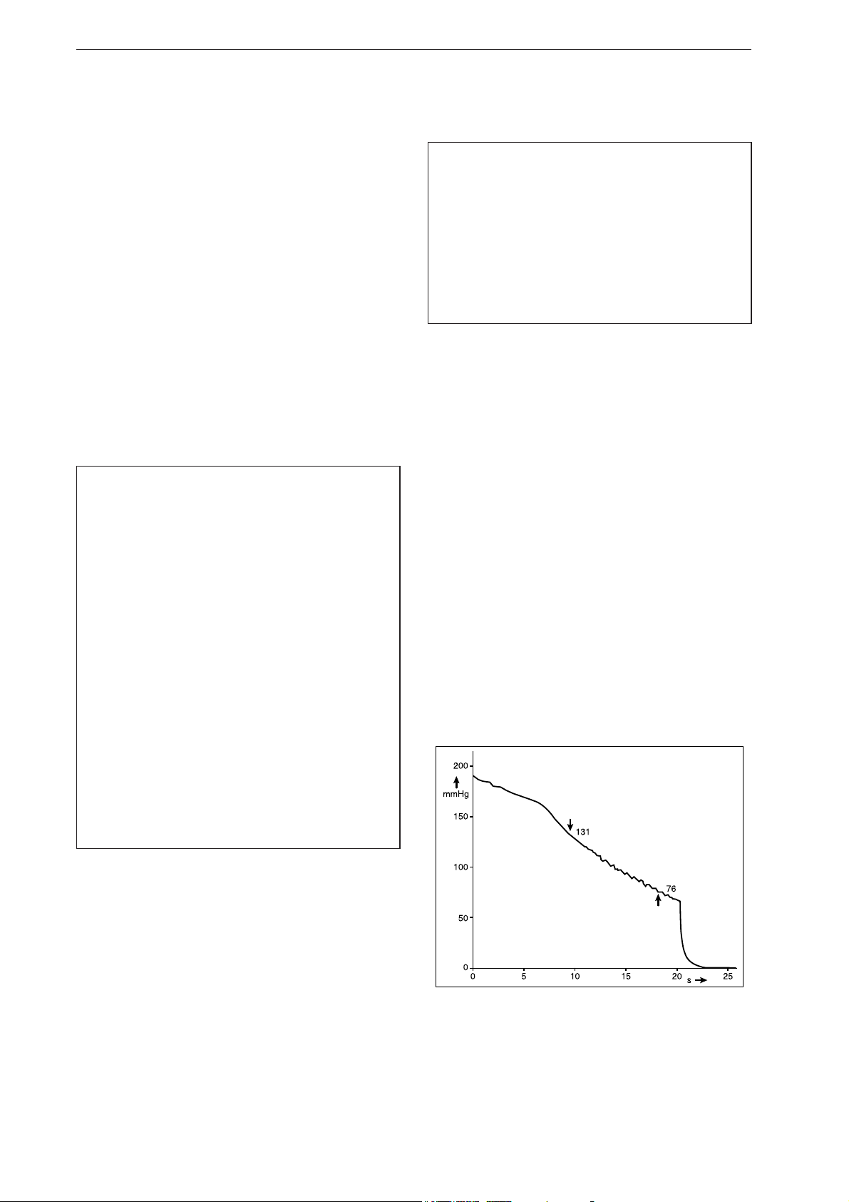
Fig. 1-1 Waveform representing the pressure decrease
in the cuff during a measurement: systolic
pressure at 131 mmHg, diastolic pressure at
76 mmHg
6 TONOPORT V 2001589-085 Revision F
Page 7

Application, Safety Information
1.2 Functional Description
The TONOPORT V monitor accommodates the blood
pressure measuring system and a microprocessor for
system control and data processing. The monitor is
powered by two AA size batteries (either rechargeable
NiMH batteries or alkaline batteries).
2001589-085 Revision F TONOPORT V 7
Page 8

1.3 Safety Information
Application, Safety Information
Danger
Risk to persons —
– The equipment is not designed for use in areas
where an explosion hazard may occur. Explosion
hazards may result from the use of flammable
anesthetic mixtures with air or with oxygen,
nitrous oxide, skin cleansing agents or
disinfectants.
Warning
Risk to persons —
–
Equipment may be connected to other
equipment or to parts of systems only when it
has been made certain that there is no danger to
the patient, the operator, or the environment as
a result. In those instances where there is any
element of doubt concerning the safety of
connected equipment, the user must contact the
manufacturers concerned or other informed
experts as to whether there is any possible
danger to the patient, the operator, or the
environment as a result of the proposed
combination of equipment. Compliance with the
standard IEC 60601-1 must always be ensured.
– TONOPORT V may be connected to CASE™ or to
a PC with the CardioSoft program. While
connected to any of these devices, TONOPORT V
must be disconnected from the patient.
–
Chemicals required for the maintenance of the
equipment, for instance, must under all
circumstances be prepared, stored, and kept at
hand in their specific containers. Failure to
observe this instruction may have severe
consequences for the patient.
–
The equipment has no protection against the
ingress of liquids. Liquids must not enter the
equipment. Equipment into which liquids have
entered must be inspected by a service
technician before use.
– Before cleaning, TONOPORT V must be
disconnected from other equipment (CASE
PC).
–
Dispose of the packaging material, observing
the applicable waste-control regulations. Keep
the packaging material out of children's reach.
™
,
8 TONOPORT V 2001589-085 Revision F
Page 9

Application, Safety Information
Warning
Incorrect measurements —
–
Magnetic and electrical fields are capable of
interfering with the proper performance of the
equipment. For this reason make sure that
external equipment operated in the vicinity of
TONOPORT V complies with the relevant EMC
requirements. X-ray equipment, MRI devices,
radio systems, etc. are possible sources of
interference as they may emit higher levels of
electromagnetic radiation.
Caution
Equipment damage, risk to persons —
– Before connecting the battery charger to the
power line, check that the voltage ratings on the
nameplate match those of your local power line.
– The battery charger is not a medical device. It
must not be used in the patient environment.
– Before using the equipment, the operator is
required to ascertain that it is in correct working
order and operating condition.
– The operator must be trained in the use of the
equipment.
– Only persons who are trained in the use of
medical technical equipment and are capable of
applying it properly are authorized to apply such
equipment.
– There are no user-replaceable components
inside the equipment. Do not open. For service
or repair, please contact your local, authorized
dealer (http://gehealthcare.com).
2001589-085 Revision F TONOPORT V 9
Page 10
Controls and Indicators
S
D
HR/min
-1
START
STOP
INFO
NBP
!
off 0
on I
TONOPORT V
1
2
3
4
8
11
10
9
6
5
7
INFO
INFO
INFO
START
STOP
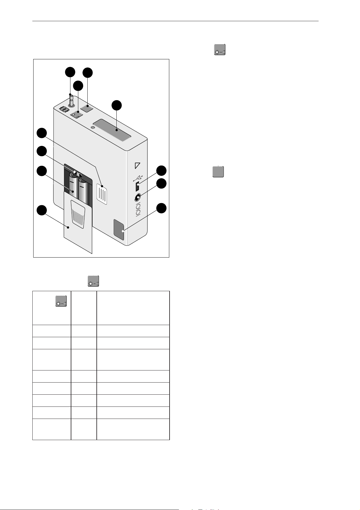
2 Controls and Indicators
1 Connection for blood pressure cuff
2 Button : push to display the most recent
parameter readings. Readings appear in the
following order:
- systolic value "S" (unit mmHg or kPa shown on the
display)
- diastolic value "D" (unit mmHg or kPa shown on
the display)
- pulse rate "HR" (unit min
-1
)
The same button is used
- to toggle between the day phase and the night
phase chapter 4, section "Toggle Manually Between
Day and Night Phase") and
- to program the BP monitor (chapter 3 "Setup")
3 Button : push to start and stop a
measurement, and to confirm entries
4 Liquid crystal display (LCD)
5 Port for connection to PC (USB)
Fig. 2-1 TONOPORT V controls and indicators
Functions of the
Button
Message
Button
Function
on
display
Push once H 1 clear memory
Push twice H 2 set date and time
Push 3 times H 3 select the measurement
Push 4 times H 4 activate calibration mode
Push 5 times H 5 display firmware version
Push 6 times H 6 select energy source
Push 7 times H 7 enable/disable audio signal
Push 8 times H 8 toggle pressure unit between
protocol
mmHg and kPa
6 Port for connection to PC (RS232)
7 Calibration mark
8 Lid covering battery compartment
9 (Rechargeable) batteries
10 ON/OFF switch
11 Nameplate
10 TONOPORT V 2001589-085 Revision F
Page 11
Controls and Indicators
0482
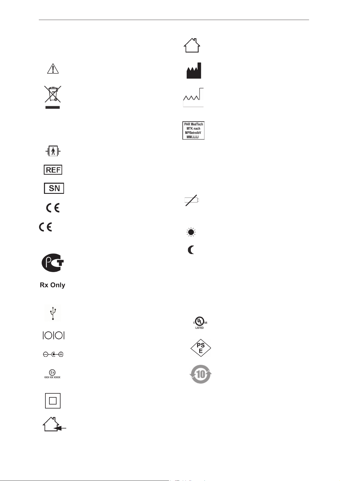
Explanation of Signs and Symbols
Symbols used on the equipment and on the packaging
For indoor use only
Caution, consult accompanying
documents
This symbol indicates that the waste of
electrical and electronic equipment must
not be disposed as unsorted municipal
waste and must be collected separately.
Please contact an authorized
representative of the manufacturer for
information concerning the
decommissioning of your equipment.
Type BF applied part
(defibrillation-proof)
Catalogue number
Serial number
CE marking
CE marked per the Medical Device
Directive 93/42/EEC of the European
Union. The notified body is MEDCERT
GmbH.
Manufacturer’s identification
Date of manufacture.
The number found under this symbol is
the date of manufacture in the YYYYMM format.
Calibration mark, valid in Germany only
(see section "Technical Inspections of the
Measuring System" in chapter 8)
Symbols used on the display
M blinks with each detected oscillation; is
continuously lit when the monitor contains
data
blinks when the batteries are almost
depleted; is continuously displayed when
batteries are discharged and no more BP
measurements can be taken
day phase selected
night phase selected
Gossudarstwenny Standart Russia
(GOST)
In the USA, the product is only for use by
or on the order of a physician, or persons
licensed by U.S. law.
USB port, connection to PC
Serial port, connection to PC
Polarity of the DC input (charger only)
Approval mark for use of the equipment
in a vehicle (charger only, xxx-xx xxxx
alphanumeric characters)
Class II equipment
For indoor use only
Further relevant symbols used on the battery charger
TR15RA120
100-240V 0.4A
47-63Hz
12V 1.1A
Power supply type designation and
ratings
UL-certified product
Approval mark for Japan
Pollution control symbol according
to the Chinese standard SJ/T113632006
2001589-085 Revision F TONOPORT V 11
Page 12
3Setup
START
STOP
INFO
START
STOP
INFO
START
STOP
START
STOP
INFO
START
STOP
START
STOP
INFO
START
STOP
INFO
START
STOP
Setup
Some Basic Facts on Battery Power
TONOPORT V is either powered by two rechargeable
Nickel Metal Hydrid batteries (NiMH) or by two alkaline
batteries. The device must be set to the power source used
(see section "Insert Batteries" below). The device also
contains a Lithium cell that powers the clock. The
Lithium cell can only be replaced by a service technician.
The capacity of two fully charged or new batteries is
sufficient for a minimum of 30 hours of operation or for
200 measurements.
The capacity of rechargeable batteries decreases with
age. If the capacity of fully charged batteries is
considerably less than 24 hours, the batteries must be
replaced.
Caution
Equipment damage —
– Only use the original rechargeable, size AA Nickel
Metal Hydrid batteries (from manufacturers such
as Sanyo, Panasonic, Energizer, Duracell, Varta,
or GP) with a capacity >
high-rate discharge alkaline batteries (such as
Panasonic Evoia, Energizer Ultimate, Duracell
Ultra, Duracell Power Pix, or Varta maxtech).
– Charge the NiMH batteries to capacity before
using them for the first time.
– Recharge the NiMH batteries immediately after
use and do not leave batteries uncharged.
– Use only the original charging unit to recharge
the NiMH batteries.
– Do not attempt to recharge the alkaline batteries.
1500 mAh or size AA
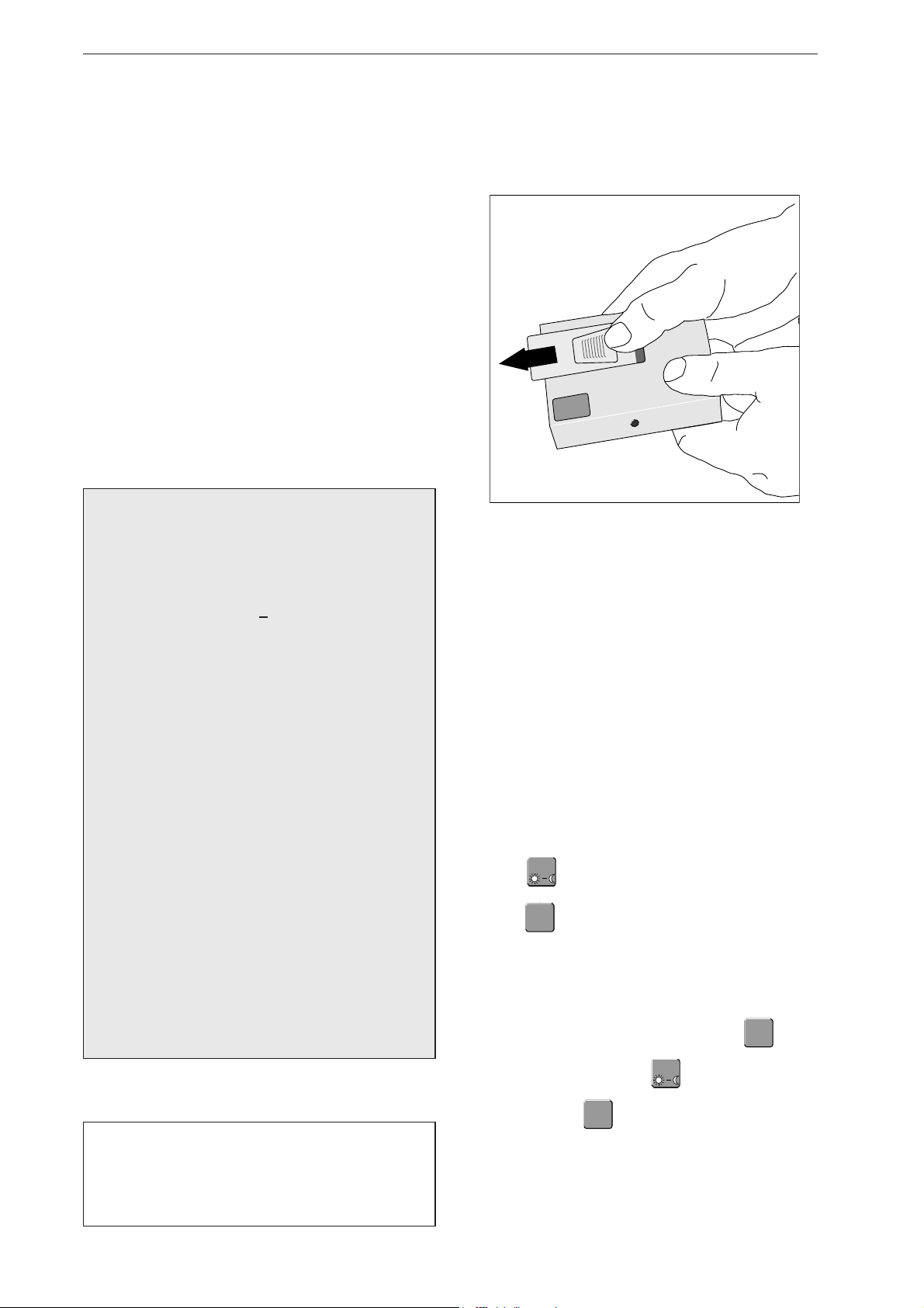
Hold TONOPORT V as shown in Fig. 3-1 and slide
the lid of the battery compartment open (approx.
1cm).
Fig. 3-1 Opening the battery compartment
It is not possible to open the lid more than about 1 cm
which is just enough to reach the ON/OFF switch. To
replace batteries, you must take off the lid (pull upward).
Place the two batteries in the compartment as indicat-
ed by the symbols.
Select Energy Source
Turn on the BP monitor. The switch is located inside
the battery compartment. Slide the switch to the right,
while looking at the display.
Wait for the time to be displayed.
– If the TONOPORT V will not be used for one
Push six times: the display shows "H 6".
month or more, remove the (rechargeable)
batteries from the device.
– Batteries must not be disposed as unsorted
municipal waste and must be collected separately.
Please contact an authorized representative of the
Push : the display will show "AAAA" when the
BP monitor is set up for rechargeable NiMH batteries
(as shipped) and "bbbb" when it is set up for alkaline
batteries.
manufacturer for information concerning the
decommissioning of the batteries.
Confirm the displayed information with or
change the selection with and confirm the new
Insert Batteries
selection with .
Note
Switch TONOPORT V off before inserting the
batteries. To do so, slide the ON/OFF switch (10,
Fig. 2-1) to the left while looking at the display.
12 TONOPORT V 2001589-085 Revision F
Next the BP monitor will briefly display the capacity
of the inserted batteries. "A 100", for instance, means
that the rechargeable batteries have a capacity of
100%, i.e., they are fully charged. "b 50" means that
Page 13

the alkaline batteries have a capacity of only 50%,
COMPIT
TC 4
2
4
3
1
i.e., they are half depleted.
Place the lid on the battery compartment and close.
Note
The energy source needs to be selected only when
the BP monitor is put into service for the first time
or when you change from NiMH to alkaline
batteries and vice versa.
Charge NiMH Batteries
Caution
Equipment damage, risk to patients —
– The charger is not a medical device. It must not
be used in the patient environment.
– The contact surface of the NiMH batteries and
of the charger must always be kept clean.
Setup
Fig. 3-2 Exchanging the connector, connecting the
charger
– The charger is to be used indoors only and must
be protected against oil, grease, aggressive
detergents and solvents to prevent damage.
– If the charger is damaged in any way, e.g. after a
drop or when the mains pins are bent, the local
authorized dealer must be contacted immediately.
– High temperatures affect the charging process.
Ideally, the room temperature should not exceed
40 °C (104 °F).
– After quick charging, please wait for some
minutes before another quick charge.
Otherwise the temperature sensors will not
function correctly.
If TONOPORT V is powered by rechargeable batteries (4
of them are shipped with the equipment), they should be
recharged immediately after use (24 hours). Use only the
original charger supplied. It consists of an AC power
adapter and the charging unit itself.
If necessary, replace the connector to match the wall
outlet type:
– push the button below the connector and hold it
depressed (1, Fig. 3-2)
– remove the connector and insert the suitable type
of connector 2, 3
– ensure that the new connector locks into place.
Connect the cable of the AC power adapter to the
charging unit 4 and plug the AC power adapter into
the wall outlet.
Insert the two batteries into the charging unit, observ-
ing the correct polarity.
Two different charger models are available:
COMPIT TC4
VARTA
Check that the voltage ratings on the nameplate of the
charging unit match those of your local power line.
2001589-085 Revision F TONOPORT V 13
Page 14

Setup
COMPIT
TC 4
Charge Batteries with the COMPIT TC4 Charger
Fig. 3-3 Red LEDs on charger
The batteries take up to 3 hours to recharge. Each of the
red LEDs corresponds to one of the charger
compartments (Fig. 3-3). During the charge cycle, the
corresponding red LED blinks at a slow rate
(approximately once per second). Note: If the red LED
does not light up, the battery may be inserted the wrong
way round. When the battery is charged, the LED is solid
red. The charging unit now trickle-charges the battery to
compensate for self-discharging.
The battery temperature is monitored in the charger.
When the temperature is too high, the LED is solid red
and the charger switches to trickle-charging.
If the battery is correctly inserted and the red LED does
not light up, the charger has identified a battery problem.
The charging current to the compartment concerned will
be cut off. Remove the battery and discard, observing the
applicable waste-disposal regulations.
Charge Batteries with the VARTA Charger
Fig. 3-4 Battery symbols and bars in the charger display
Insert 4 or 2 batteries. To charge only 2 batteries, insert
them in the two compartments on the right or on the left.
The batteries take up to 3 hours to recharge. Once the
batteries are inserted, battery symbols will appear in the
charger display where each symbol corresponds to one of
the charger compartments (Fig. 3-4). During the charge
cycle, the corresponding bar in the battery symbols
blinks. Note: If the battery symbols and bar do not light
up, only one battery may be inserted or the batteries are
inserted the wrong way round. When the batteries are
charged, the bars are permanently illuminated. The
charging unit now trickle-charges the battery to
compensate for self-discharging.
The battery temperature is monitored in the charger.
When the temperature is too high, the bar in the battery
symbol is permanently illuminated and the charger
switches to trickle-charging.
If the batteries are correctly inserted and the displayed
battery symbols show no bars, the charger has identified
a battery problem. The charging current to the
compartment concerned will be cut off. Remove the
battery and discard, observing the applicable waste-
disposal regulations.
14 TONOPORT V 2001589-085 Revision F
Page 15

Performance Check
M
kPa mmHg
M
START
STOP
INFO
START
STOP
INFO
START
STOP
START
STOP
INFO
START
STOP
START
STOP
INFO
START
STOP
Setup
When turned on, TONOPORT V runs a self-test that
includes all symbols and segments on the LCD (Fig. 3-5).
Then it checks the batteries and indicates the remaining
capacity. "A 100", for instance, means that the
rechargeable batteries have a capacity of 100%, i.e., they
are fully charged. "b 50" means that the alkaline batteries
have a capacity of only 50%, i.e., they are half depleted.
The minimum battery capacity for a 24-hour
measurement is 90%.
If the capacity is below 90%, new or fully charged
batteries must be inserted.
BP monitors that have passed the self-test and completed
the battery test will indicate the following information:
– the time of day
– the measuring phase (day / night )
– whether or not data are stored in the BP monitor (M)
(Fig. 3-6).
The BP monitor will also emit an audio signal, if enabled.
Note
When using TONOPORT V in conjunction with
CASE™ / CardioSoft, it is recommended to
perform the first three steps at the PC.
Clear the Memory
The symbol M on the display indicates that memory
contains BP data. If these data still need to be analyzed,
refer to chapter 5 "Data Output" for details on data
evaluation. If you do not need the data any more, delete it
as follows:
Briefly switch TONOPORT V off and on again and
wait for the time to be displayed.
Push : the display indicates "H 1".
Push : the display indicates "LLLL".
To delete the data, push again: the display indi-
cates "0000", followed by the time (if you do not wish
to clear the memory, turn off the BP monitor instead
Fig. 3-5 Test display on LCD
Fig. 3-6 Example: display after successful self-test
(M= BP data in memory,
measuring phase: day)
Before using TONOPORT V on a patient
1. clear the memory
2. check date and time and correct, if required
of pushing ).
3. select a measurement protocol
4. enable or disable the audio signal.
2001589-085 Revision F TONOPORT V 15
Page 16

Setup
START
STOP
INFO
START
STOP
INFO
START
STOP
START
STOP
INFO
START
STOP
START
STOP
INFO
START
STOP
INFO
START
STOP
START
STOP
INFO
START
STOP
START
STOP
INFO
START
STOP
INFO
START
STOP
START
STOP
INFO
START
STOP
INFO
START
STOP
START
STOP
INFO
START
STOP
START
STOP
INFO
START
STOP
INFO
START
STOP
START
STOP
INFO
START
STOP
INFO
START
STOP
START
STOP
INFO
START
STOP
START
STOP
INFO
START
STOP
INFO
START
STOP
START
STOP
INFO
START
STOP
INFO
START
STOP
START
STOP
INFO
START
STOP
START
STOP
INFO
START
STOP
INFO
START
STOP
Time and Date
Usually the BP monitors are set to the correct time and
date before delivery. Therefore, the time only needs to be
corrected to change between Standard Time and Daylight
Saving Time.
Setting Date and Time
Briefly switch TONOPORT V off and on again and
wait for the time to be displayed.
Push twice: the display indicates "H 2".
Push : the display indicates the year, e.g.
"2009".
If the indicated year is correct, confirm it with
or correct it with and confirm with .
– The display indicates the month, e.g. "03".
Measurement Protocols
There is a choice of three different measurement
protocols:
Protocol Day Phase
(7 a.m. to 10 p.m.)
P1 every 15 minutes every 30 minutes
P2 every 20 minutes every 40 minutes
P3 every 30 minutes every 60 minutes
Max. inflation pressure: day phase 250 mmHg
night phase 220 mmHg
Select a Measurement Protocol
Briefly switch TONOPORT V off and on again and
wait for the time to be displayed.
Night Phase
(10 p.m. to 7 a.m.)
If the indicated month is correct, confirm it with
or correct it with and confirm with .
In the same manner, correct day, hour and minute.
In the end, the time of day will be displayed again.
Selecting the Pressure Unit
Briefly switch TONOPORT V off and on again and
wait for the time to be displayed.
Push eight times: the display indicates "H 8".
Push : the display indicates "mmHg" or "kPa".
Confirm the pressure unit with or select the oth-
er unit with , then confirm with .
Push three times: the display indicates "H 3".
Push : the display indicates "LLLL" (Selecting
a protocol automatically clears the memory. If you do
not wish to clear the memory, turn the BP monitor
off.)
Push : the display indicates "P1" (protocol 1).
Using , select protocol 2 or 3
OR
Confirm the displayed protocol with .
Enable or Disable the Audio Signal
Briefly switch TONOPORT V off and on again and
wait for the time to be displayed.
Push seven times: the display indicates "H 7".
Push : the display indicates "0000" when the au-
dio signal is turned off, and "1111" when it is turned
on.
Either confirm the setting with or press to
select the alternate setting and confirm with .
16 TONOPORT V 2001589-085 Revision F
Page 17

Application
4 Application
Symbols used on the cuff Cleaning the Cuffs
– Use a moist cloth to wipe the cuffs clean if they are
Refer to Operator Manual.
Follow the instructions in the
Operator Manual.
Cuff suitable for adult patients of
the indicated height (see man in
box). Adult-sized cuffs are availab-
le as standard, small, large and extra
large.
BP cuff suitable for the indicated
arm circumference.
only slightly soiled.
– Clean cuffs that are heavily contaminated by washing
them with soapy water or a suitable cleaning agent
that contains a disinfectant (do not machine-wash).
Ensure that no liquid penetrates into the cuff bladder
or the pressure tubing (for this reason, remove the
bladder from the cuff before cleaning).
– After cleaning, rinse the cuff thoroughly with water
and let it dry at room temperature for about 15 hours.
– The cuffs can be disinfected with isopropyl alcohol
70%, ethanol 70%, Microzid, Buraton liquid,
Sporicidin or Cidex. After disinfection, rinse the cuff
thoroughly with tap water and air-dry.
BP cuff width.
When the cuff is applied, this label
must face the skin.
When the cuff is applied, these two
arrows must be located over the
brachial or femoral artery.
This line identifies the end of the
cuff which must be situated within
the range identified by the INDEX
label when the cuff is closed.
The end of the cuff must be situated
within this range when the cuff is
closed.
Latex-free BP cuff.
CE marking, cuff fulfills EU
directives.
2001589-085 Revision F TONOPORT V 17
Page 18

Fig. 4-1 Applying the cuff
Index
Index
Index
Application
Applying the Cuff
Warning
Risk to persons —
Disconnect TONOPORT V from other equipment
(CASE™, PC) before connecting it to the patient.
Always insert two fully charged NiMH batteries or
two new alkaline batteries, before starting a measure-
ment.
Check that the memory has been cleared (see “Clear
the Memory” on page 15).
Select the appropriate cuff size (see cuff label). When
the cuff is too small the BP values will be overrat-
ed, when it is too big, the measured values will be
too low.
Fig. 4-2 Applying the cuff
Caution
Incorrect measurements —
– Use only the cuffs listed in chapter 10 "Order
Information".
– Replace cuffs on a regular basis. Damaged
Velcro fasteners may cause incorrect readings.
Place the cuff on that arm of the patient that is used
less frequently during normal daily activities. On
adults it should be placed about 2 fingers' breadth
above the bend of the elbow; on children, a little
closer. Bending the arm must not change the cuff
level. Verify that
– the cuff tubing points up toward the shoulder (Fig.
4-1)
– the side with the label is on the skin
– the arrow is located above the brachial or femoral
artery
– the dashed white line at the end of the cuff is
located between the two dashed lines
when you close the cuff (if this is not the case,
select another cuff size, Fig. 4-2)
– the cuff fits snugly around the arm, but does not
compress the blood vessels.
18 TONOPORT V 2001589-085 Revision F
Page 19

Application
START
STOP
INFO
START
STOP
START
STOP
INFO
START
STOP
START
STOP
INFO
START
STOP
START
STOP
INFO
START
STOP
START
STOP
INFO
START
STOP
START
STOP
INFO
START
STOP
START
STOP
INFO
START
STOP
START
STOP
INFO
START
STOP
Initiate a Trial Measurement
Turn on TONOPORT V and place it in the carrying
pouch. There is an aperture in the pouch to accommo-
date the cuff connection tube.
Attach the pouch to the patient (shoulder strap, belt).
For reasons of hygiene, it is not advised to carry the
pouch on the bare skin.
Guide the pressure tubing around the patient's neck as
a strain relief and connect it to the blood pressure cuff
port on the TONOPORT V (1, Fig. 2-1). Advise the
patient to avoid kinking the tubing during the mea-
surement.
Check that the display indicates the time of day. If the
memory contains data from a previous procedure, the
letter "M" will appear on the display when you turn on
the device. If you still try to initiate a measurement,
the message "LLLL" prompts you to clear the memo-
ry. Push twice to delete the data. If you do not
wish to delete the data, turn off the device instead of
Patient Information
Advise your patient
– not to move while a measurement is being taken to
avoid motion artifacts that may lead to erroneous
readings and to keep the cuff inflation time as
short as possible
– to place TONOPORT V on the night stand while in
bed
– how to switch the device manually from the day to the
night phase (see page 19)
– that events considered important should be noted
down in a diary and that intermediate measurements
can be initiated with
– that the measurement can be stopped at any time with
(the cuff will be deflated)
– not to open the battery compartment
– about the audio signal and its meaning.
pushing .
To avoid erroneous measurements, ensure that the
patient does not move during the trial measure-
ment. The patient may stand or sit.
Push to initiate the first measurement.
Within a few seconds, the device starts inflating the cuff.
When the inflation pressure has been reached, the cuff
will gradually be deflated. The changing cuff pressure is
indicated on the display and the letter "M" appears with
each detected oscillation. At the end of the measurement
the measured data appears in the following order
– the systolic reading (S in mmHg or kPa)
– the diastolic reading (D in mmHg or kPa)
– the pulse rate (HR/min
-1
).
If an error code, such as "E 29" (insufficient number of
oscillations detected) is displayed after the measurement,
tighten the cuff a little and push again (see also
Warning
Risk to persons —
Instruct your patient
– to terminate the measurement with ,
whenever the cuff is not deflated within about
2minutes,
– to remove the cuff if it is not deflated after
activation of the button. This could be due
to kinked tubing. The cuff must be reapplied as
described earlier before additional
measurements can be taken.
chapter 6 "Error Codes").
If the trial measurement has been successfully completed,
the device is ready for automatic measurements.
2001589-085 Revision F TONOPORT V 19
Page 20

Application
START
STOP
INFO
START
STOP
INFO
General Information on Ambulatory BP
Measurement
These are the buttons on TONOPORT V used during an
ambulatory blood pressure measurement:
starts and stops a measurement
displays the most recent measurement results
or the most recent error message, toggles
between day and night phase (see next section)
For the first measurement, the cuff is inflated to a
pressure of 160 mmHg (initial pressure). For subsequent
measurements, the device inflates the cuff to a pressure
which is 15 mmHg above the systolic value of the
previous measurement (minimum inflation pressure:
120 mmHg).
If the measuring value is above the inflation pressure, the
device will increase the cuff pressure another 50 mmHg.
Toggle Manually Between Day and Night
Phase
In the three measurement protocols the day phase lasts from
7 a.m. to 10 p.m. and the night phase from 10 p.m. to 7 a.m.
On the display the two phases are represented by the
symbols (day) and
Patients whose day and night phases are different from
these predefined periods can push the button twice
to change from one phase to the other.
If the measurement protocol was created with
CASE™ / CardioSoft and only 1 BP period has
been specified, switching from one phase to the
other will leave the measurement intervals
unchanged. They will always be the same. The
information "day phase" and "night phase" is only
used to identify the measurements.
(night).
Note
A manual measurement can be taken at any time between
the automatic measurements. Manual measurements are
identified with the "+" symbol in the tabular BP data.
The device will repeat a measurement after 2 minutes, if
unsuccessful. An error code referring to failed
measurements is generated only after three consecutive
unsuccessful measurements.
Error codes E02 (battery depleted), E06 (inflation time
over) and E08 (200 measurements taken) do not lead to a
second measurement. The next measurement after error
code E06 takes place at the selected interval.
After error codes E02 and E08, the device enters the
power-save mode to prevent over-discharging of the
rechargeable batteries. This mode can only be terminated
by turning the device off and on again.
Audio Signal
If enabled (see page 16), the audio signal will be emitted
in the following situations:
– shortly after TONOPORT V was switched on
– just before TONOPORT V starts inflating the cuff
(during the day phase only)
– after TONOPORT V has detected an erroneous
measurement
20 TONOPORT V 2001589-085 Revision F
Page 21

5 Data Output
TONOPORT V
S
D
HR/min
-1
START
STOP
INFO
NBP
!
a
b
Data Output
The measurement data are output via CASE™ /
CardioSoft.
Warning
Risk to persons —
While connected to the patient, TONOPORT V
must be disconnected from other equipment
(CASE™, PC).
Note
If the USB port is used (CardioSoft only), it is
necessary to install the appropriate driver first (see
“Software Installation” on page 23).
CASE™ must always be connected to the serial
port.
Put the PC-based system into operation (see CASE™
or CardioSoft Operator Manual).
For more information about data output, please refer to
the Operator Manual of CASE™ or CardioSoft.
When you have finished downloading data to CASE™ /
CardioSoft and do not intend to continue working with
this system, disconnect TONOPORT V and turn it off.
Turn off TONOPORT V.
Connect TONOPORT V to the PC system:
– via cable 2001589-040, if the USB port of
TONOPORT V is used (a Fig. 5-1)
– via cable 2001589-011, if the serial port of
TONOPORT V is used (b Fig. 5-1)
Turn on TONOPORT V and wait for the time to be
displayed on TONOPORT V.
Fig. 5-1 Connections for PC cable
aUSB port
b RS232 port
2001589-085 Revision F TONOPORT V 21
Page 22

6 Error Codes
Error Codes
E 02 Batteries depleted. Code appears when the
battery capacity is insufficient for new BP
measurements. The device differentiates
between two states: the memory has just been
cleared (i.e., the battery test is performed with a
higher drain to ensure that fresh batteries will be
inserted at the beginning of the measurement) or
measurements have already been taken.
E 03 Measurement time over. Code is displayed after
a measurement duration of 180 seconds.
E 06 Inflation time over. The maximum inflation time
of 130 seconds has elapsed. This condition
indicates a leak in the cuff or tubing, or a
defective connection to the blood pressure cuff.
E 07 This code appears
– when the device could not determine a
systolic value although the cuff pressure was
already increased twice
– when the current cuff pressure would exceed
the selected maximum pressure.
E 08 200 pressure measurements taken; storage
capacity exhausted.
E 14 Diastolic reading below 40 mmHg. Code
appears when the cuff pressure has dropped to
40 mmHg and no diastolic pressure could be
identified (TONOPORT V does not measure
diastolic pressures below 40 mmHg).
E 15 Motion artifact during diastole detection.
E 17 Internal hardware error. Please contact your
local, authorized dealer
(http://gehealthcare.com).
E 18 Systolic reading outside measuring range.
E 19 Diastolic reading outside measuring range.
(Codes E 18 and E 19 are displayed when the
systolic and diastolic values are outside the
range in which oscillations were detected.)
E 21 Difference between systolic and diastolic
pressure too small (10 mmHg or less).
E 22 Motion artifact during systole detection.
E 24 No systole detected in the provided time frame.
E 26 Systolic reading below measuring range.
E 27 Systolic reading above measuring range.
E 29 Insufficient number of oscillations detected: For
a correct measurement, the system must detect a
minimum of 8 oscillations. Tighten the cuff so
that one finger, but not two, can be inserted
between the patient's arm and the cuff. At the
same time the device switches to a deflation rate
of 4 mmHg/s. When it detects more than 13
oscillations later on, the rate changes to
6 mmHg/s.
22 TONOPORT V 2001589-085 Revision F
Page 23

7 Software Installation
Software Installation
Install CardioSoft and the USB driver on your PC only if
you are familiar with the Windows operating system.
CardioSoft from version 6.73 SP2 and the USB driver
run only under these operating systems: Windows 8.1 Pro
and Enterprise 64-bit as well as Windows 7 Professional
32-bit, 64-bit.
CardioSoft version 6.7 (except 6.73 SP2) and the USB
driver run only under these operating systems: Windows
7 Professional 32-bit, 64-bit, and Windows XP
Professional 32-bit with Service Pack 3.
CardioSoft version 6.6 and the USB driver run only
under these operating systems: Windows XP
Professional, Windows Vista Home Premium 32-bit, and
Windows Vista Business 32-bit.
CardioSoft pre version 6.6 and the USB driver run
under these operating systems: Windows 2000, Windows
XP Professional, Windows Vista Home Premium 32-bit,
and Windows Vista Business 32-bit.
CardioSoft (Standalone Workstation)
You will need administrator privileges for installation of
the USB driver.
1. Turn on the PC and the monitor. Exit ALL
programs.
2. Insert the CardioSoft CD in the CD ROM drive. If
the CD drive does not automatically start up, start
"setup.exe" (on the CardioSoft CD, "Disk1" or
"CASE-CS" folder) via the Windows Explorer.
USB Driver
You will need administrator privileges for installation of
the USB driver.
1. Turn on the PC and the monitor. Exit ALL
programs.
2. Insert the CD with the USB drivers in the CD ROM
drive. If the CD drive does not automatically start
up, start "setup.exe" (on the USB driver CD,
"Disk1" folder) via the Windows Explorer.
3. Follow the displayed prompts. Select Allow if the
system informs you that you are using an
unidentified program.
4. Click Finish to complete the first part of the USB
driver installation procedure.
5. Turn on TONOPORT V and connect it to the PC,
using the USB connection cable.
Windows will automatically detect TONOPORT V
(TUSB3410).
6. Follow any additional prompts that may be
displayed.
7. When Windows indicates that the drivers were
successfully installed and the new hardware can be
used, remove the USB driver CD from the CD-
ROM drive.
3. Follow the displayed prompts.
4. Confirm the two proposed directories with Next.
5. Enter the serial number (see CD-ROM).
CardioSoft will now be installed on your computer.
6. Restart Windows.
Note
If you will be using the serial port of TONOPORT V
(Fig. 5-1, b) installation is now complete.
To be able to use the USB port of TONOPORT V
(Fig. 5-1, a), you will have to install the USB driver
and check the communication as described below.
2001589-085 Revision F TONOPORT V 23
Page 24

Software Installation
USB Port Verification
For verification of the USB port, turn on TONOPORT V
and connect its USB port to the PC.
1. Start the Device Manager of the operating system.
2. Double-click Ports (COM and LPT) to view all
ports.
If CardioSoft version 6.72 or higher is used or if a
USB serial port (TUSB3410 Device) between COM1
and COM4 has been selected, it is not necessary to
choose another port. Note down the selection, because
the same port must be set in CardioSoft, and close all
windows to return to the Windows desktop.
If a USB serial port greater than COM4 has been
selected one of the ports COM1 through COM4 must be
disabled at the PC so that it can be assigned to the USB
port.
3. Select one of the ports COM1 through COM4 that
is not needed for other devices and disable it (right-
click > Disable). Confirm the message that the
device will not be functional any longer.
4 Right-click USB - Serial Port (COM X) and click
Properties.
5. Click Port Settings > Advanced and at COM Port
Number select the port that you disabled earlier.
Select Yes, if a message appears that this COM port
is already used by another device. The selected port
must also be set in CardioSoft.
6. Select OK where needed and/or close all windows
to save the settings.
7. Disconnect the USB cable and restart Windows.
24 TONOPORT V 2001589-085 Revision F
Page 25

Cleaning, Maintenance, Disposal
8 Cleaning, Maintenance, Disposal
8.1 Cleaning, Disinfection
Equipment Surface
Warning
Shock hazard —
Disconnect TONOPORT V from the PC before
cleaning.
Turn off TONOPORT V.
Wipe the device down with a soft, lint-free cloth, us-
ing a mild cleaning solution or dish liquid in a low
concentration. Many cleaning agents and disinfec-
tants commonly used in hospitals are suitable. Do not
let liquid enter the device.
Caution
Equipment damage —
Do not disinfect the device surface with phenol-
based disinfectants or peroxide compounds.
8.2 Maintenance
Checks before each use
Before each use visually check the device and the ca-
bles for signs of mechanical damage.
If you detect damages or impaired functions which may
result in a hazard to the patient or the operator, the device
must be repaired before it can be used again.
Technical Safety Inspections
For safety, the devices require regular maintenance. To
ensure functional and operational safety of
TONOPORT V, Technical Safety Inspections should be
carried out on an annual basis.
These checks should be performed by persons with
adequate training and experience.
The checks can be carried out by GE Healthcare within
the framework of a service agreement. Please contact
your local, authorized dealer for details.
Warning
Shock hazard, equipment damage —
Equipment into which liquids have entered must be
inspected by a service technician before use.
Cuffs
For cuff cleaning information, see “Cleaning the Cuffs”
on page 17.
Cables
Disconnect cables from the device before cleaning.
Use a cloth moistened with soapy water to wipe the
cables clean. Do not immerse cables in liquid.
The nature and scope of these checks are explained in the
corresponding sections of the Service Manual.
On request GE Healthcare will provide a detailed Service
Manual.
The device does not require any other maintenance.
Technical Inspections of the Measuring
System
The non-invasive pressure measurement system of
TONOPORT V should be inspected every two years.
These checks should be performed by persons with
adequate training and experience.
The checks can be carried out by GE Healthcare within
the framework of a service agreement. Please contact
your local, authorized dealer for details.
The nature and scope of these checks are explained in the
corresponding sections of the service manual.
On request GE Healthcare will provide a detailed Service
Manual.
2001589-085 Revision F TONOPORT V 25
Page 26

Cleaning, Maintenance, Disposal
START
STOP
INFO
START
STOP
INFO
START
STOP
START
STOP
INFO
START
STOP
START
STOP
INFO
START
STOP
START
STOP
INFO
START
STOP
INFO
START
STOP
START
STOP
INFO
START
STOP
Disposal of the Product Calibration Mode
The product described in this operator manual
must not be disposed as unsorted municipal
waste and must be collected separately. Please
contact an authorized representative of the
manufacturer for information concerning the
decommissioning of your equipment.
(e.g. to check the pneumatic system for leaks)
Connect a rubber bulb between pressure tubing and
cuff, using a T-adapter.
Roll up cuff tight.
Switch off device and switch it on again after a few
seconds.
Wait for time to be displayed.
Push four times: the display indicates "H 4".
Push : the display indicates an internal value that
must be between 25 and 100. If the displayed value is
outside this range, TONOPORT V must be returned
for repair.
Push again: the display indicates "0" (the dis-
play now indicates the pressure in mmHg).
Generate a test pressure of 200 mmHg and measure
the pressure decrease after waiting at least 30 sec-
onds. (Pressure decreases between 3 and 5 mmHg are
typical; a pressure decrease > 6 mmHg indicates a
leak and the system needs to be repaired.)
Push to exit the calibration mode.
View Firmware Version
Turn on the device and wait for the time to be dis-
played.
Push five times: the display indicates "H 5".
Push : the firmware version is indicated, e.g.
– "21:00" = firmware version 2.1
Push to end the display.
26 TONOPORT V 2001589-085 Revision F
Page 27

9 Technical Specifications
Technical Specifications
Measuring Range
– systolic pressure: 60 to 260 mmHg
(8.0 to 34.6 kPa)
– diastolic pressure: 40 to 220 mmHg
(5.3 to 29.3 kPa)
– mean pressure: 50 to 250 mmHg
(6.7 to 33.3 kPa)
– pulse rate (HR): 35 to 240 min
-1
Measurement Accuracy (determined in a clinical
study)
– systematic measurement deviation
-0.7 mmHg (systolic)
-0.8 mmHg (diastolic)
– empirical standard deviation
4.6 mmHg (systolic)
4.4 mmHg (diastolic)
Acquisition Period
– up to 30 hours or 200 measurements
Interfaces
Environment
Operation
– temperature between +10 and +40 °C
– relative humidity between 15 and 85 %, no
condensation
– atmospheric pressure between 700 hPa and 1060 hPa
– altitude (relative to sea level) -400 to 2800 meters
Transport and Storage
– temperature between -20 and + 70 °C
– relative humidity between 10 and 90 %, no
condensation
– atmospheric pressure between 500 hPa and 1060 hPa
– altitude (relative to sea level) -400 to 4500 meters
Dimensions and Weight
–height 27 mm
– width 80 mm
– depth 100 mm
– weight 199 g, incl. batteries
– USB (1.1 or 2.0)
–RS232
Battery
– 2 AA size rechargeable NiMH batteries, 1.2 V,
>
1500 mAh or
– 2 AA size alkaline batteries
Battery Charge Time
– 2 to 3 hours
Maximum Cuff Pressure
– 300 mmHg
Measuring Method
– oscillometric
Battery Charger
– protection class II, IP20
– 100 to 240 VAC 50/60 Hz, 0.5 A
Protection Class
–IP 20
2001589-085 Revision F TONOPORT V 27
Page 28

10 Order Information
Order Information
Accessories
TONOPORT V Ambulatory Blood
Pressure System
TONOPORT V recording unit
Connection cable TONOPORT V to
PC (USB)
Connection cable TONOPORT V to
PC (RS232)
Battery charging unit
Rechargeable NiMH batteries (4,
size AA)
Carrying pouch
Belt for carrying pouch
Blood pressure cuff for adults,
standard, width 13 cm, for
circumference between 24 and
32 cm, Rectus connector
TONOPORT V Operator Manual
CardioSoft CD
USB driver CD
2001589-041 Battery charging unit
2001589-014 Rechargeable NiMH battery
737 000 08 Alkaline battery, 1.5 V
2001589-015 Carrying pouch
2001589-016 Belt for carrying pouch
2001589-040 Connection cable TONOPORT V to PC
2001589-011 Connection cable TONOPORT V to PC
2001589-212 Blood pressure cuff for adults, standard,
(device requires 2)
(device requires 2)
(USB), length approx. 1.5 meters
(RS232), length approx. 1.2 meters
width 13 cm, for circumference
between 24 and 32 cm, Rectus
connector
2001589-211 Blood pressure cuff for adults, small,
width 9 cm, for circumference between
17 and 26 cm, Rectus connector
2001589-213 Blood pressure cuff for adults, large,
width 15 cm, for circumference
between 32 and 42 cm, Rectus
connector
2001589-214 Blood pressure cuff for adults, extra
large, width 15 cm, for circumference
between 38 and 46 cm, Rectus
connector
2001589-093 USB driver CD
28 TONOPORT V 2001589-085 Revision F
Page 29

Electromagnetic Compatibility (EMC)
11 Appendix - Electromagnetic
Compatibility (EMC)
Changes or modification to this system not expressly
approved by GE Healthcare could cause EMC issues with
this or other equipment This system is designed and
tested to comply with applicable regulation regarding
EMC. It needs to be installed and put into service
according to the EMC information stated as follows.
Guidance and Manufacturer’s Declaration – Electromagnetic Emissions
TONOPORT V is intended for use in the electromagnetic environment specified below. It is the responsibility of the
customer or user to ensure that TONOPORT V is used in such an environment.
Use of portable phones or other radio frequency
(RF) emitting equipment near the system may cause
unexpected or adverse operation.
The equipment or system should not be used
adjacent to, or stacked with, other equipment. If
adjacent or stacked use is necessary, the equipment
or system should be tested to verify normal
operation in the configuration in which it is being
used.
Warning
Warning
Emissions Test Compliance Electromagnetic Environment - Guidance
RF emissions to EN 55011/
CISPR 11
RF emissions to EN 55011/
CISPR 11
Harmonic emissions to EN
61000-3-2/IEC 61000-3-2
Voltage fluctuations/flicker
emissions to EN 61000-3-3/IEC
61000-3-3
Group 1 TONOPORT V uses RF energy only for its internal
function. Therefore, its RF emissions are very low and
are not likely to cause any interference in nearby
electronic equipment.
Class B TONOPORT V is suitable for use in all
establishments, including domestic and those directly
not applicable
not applicable
connected to the public low-voltage power supply
network that supplies buildings used for domestic
purposes.
2001589-085 Revision F TONOPORT V 29
Page 30

Electromagnetic Compatibility (EMC)
Guidance and Manufacturer’s Declaration – Electromagnetic Immunity
TONOPORT V is intended for use in the electromagnetic environment specified below. It is the responsibility of the
customer or user to ensure that TONOPORT V is used in such an environment.
Immunity Test EN/IEC 60601 Test Level Compliance
Electrostatic discharge
(ESD) to EN 61000-4-2/
± 6 kV contact
± 8 kV air
± 6 kV
± 8 kV
IEC 61000-4-2
Electrical fast transient/
burst to EN 61000-4-4/
IEC 61000-4-4
Surge to EN 61000-4-5/
IEC 61000-4-5
Voltage dips, short
interruptions and voltage
variations on power
supply input lines to EN
61000-4-11/IEC61000-4-
11
± 2 kV for power supply
lines
± 1 kV for input/output lines
± 1 kV differential mode
± 2 kV common mode
< 5 % U
(> 95 % dip in UT)
T
for 0.5 cycles
40 % U
(60 % dip in UT) for
T
5cycles
70 % U
(30 % dip in UT) for
T
not
applicable
not applicable
not applicable
not applicable
not applicable
not applicable
not applicable
25 cycles
Level
Electromagnetic Environment -
Guidance
Floors should be wood, concrete or
ceramic tile. If floors are covered with
synthetic material, the relative humidity
should be at least 30%.
Mains power should be that of a typical
commercial or hospital environment.
Mains power should be that of a typical
commercial or hospital environment.
Mains power should be that of a typical
commercial or hospital environment. If
the user of TONOPORT V requires
continued operation during power mains
interruptions, it is recommended that
TONOPORT V be powered from an
uninterruptible power supply or a battery.
Power frequency (50/
60 Hz) magnetic field to
EN 61000-4-8/IEC 61000-
4-8
NOTE U
is the AC mains voltage prior to application of the test level.
T
< 5 % U
(> 95 % dip in UT)
T
not applicable
for 5 s
3 A/m 3 A/m Power frequency magnetic fields should
be at levels characteristics of a typical
location in a typical commercial or
hospital environment.
30 TONOPORT V 2001589-085 Revision F
Page 31

Electromagnetic Compatibility (EMC)
PPP
Guidance and Manufacturer’s Declaration – Electromagnetic Immunity
TONOPORT V is intended for use in the electromagnetic environment specified below. It is the responsibility of the
customer or user to ensure that TONOPORT V is used in such an environment.
Immunity Test EN/IEC 60601 Test Level Compliance
Conducted RF to
EN 61000-4-6/IEC 61000-
3 Vrms
150 kHz to 80 MHz
3 Vrms
4-6
Radiated RF to EN 61000-
4-3/IEC 61000-4-3
3 V/m
80 MHz to 2.5 GHz
3 V/m
Level
Electromagnetic Environment -
Guidance
Portable and mobile RF communications
equipment should be used no closer to any
part of TONOPORT V, including cables,
than the recommended separation distance
calculated from the equation applicable to
the frequency of the transmitter.
Recommended separation distance:
d = 1.17
d = 1.17 80 MHz to 800 MHz
d = 2.33 800 MHz to 2.5 GHz
where P is the maximum output power
rating of the transmitter in watts (W)
according to the transmitter manufacturer
and d is the recommended separation
distance in meters (m).
Field strengths from fixed RF transmitters,
as determined by an electromagnetic site
a
survey
compliance level in each frequency range
, should be less than the
b
Interference may occur in the vicinity of
equipment marked with the following
symbol
NOTE 1 At 80 MHz and 800 MHz, the higher frequency range applies.
NOTE 2 These guidelines may not apply in all situations. Electromagnetic propagation is affected by absorption and
reflection from structures, objects, and people.
.
2001589-085 Revision F TONOPORT V 31
Page 32

Electromagnetic Compatibility (EMC)
PPP
a) Field strengths from fixed transmitters, such as base stations for radio (cellular/cordless) telephones and land
mobile radio, AM and FM radio broadcast and TV broadcast cannot be predicted theoretically with accuracy. To
assess the electromagnetic environment due to fixed RF transmitters, an electromagnetic site survey should be
considered. If the measured field strength in the location in which TONOPORT V is used exceeds the applicable
RF compliance level above, TONOPORT V should be observed to verify normal operation. If abnormal
performance is observed, additional measures may be necessary, such as reorienting or relocating the equipment.
b) Over the frequency range 150 kHz to 80 MHz, field strengths should be less than 3 V/m.
Recommended separation distances between portable and mobile RF communication equipment and
TONOPORT V
TONOPORT V is intended for use in the electromagnetic environment in which radiated RF disturbances are
controlled. The customer or the user of TONOPORT V system can help prevent electromagnetic interference by
maintaining a minimum distance between portable and mobile RF communications equipment (transmitters) and
TONOPORT V as recommended below, according to the maximum output power of the communications equipment
Rated Maximum Output
Power of Transmitter
Separation Distance According to Frequency of Transmitter
[m]
[W]
150 kHz to 80 MHz
d = 1.17
80 MHz to 800 MHz
d = 1.17
800 MHz to 2.5 GHz
d = 2.33
0.01 0.12 0.12 0.24
0.1 0.37 0.37 0.74
1 1.17 1.17 2.34
10 3.69 3.69 7.38
100 11.67 11.67 23.34
For transmitters rated at a maximum output power not listed above, the recommended separation distance d in meters
(m) can be estimated using the equation applicable to the frequency of the transmitter, where P is the maximum
output power rating of the transmitter in watts (W) according to the transmitter manufacturer.
NOTE 1 At 80 MHz and 800 MHz, the higher frequency range applies.
NOTE 2 These guidelines may not apply in all instances. Electromagnetic propagation is affected by absorption and
reflection from structures, objects and people.
32 TONOPORT V 2001589-085 Revision F
Page 33

Electromagnetic Compatibility (EMC)
Compliant Cables and Accessories
Warning
The use of accessories, transducers and cables
other than those specified may result in increased
emissions or decreased immunity performance of
the equipment or system.
The list below shows the accessories that have been
tested and found EMC compliant for use with
TONOPORT V.
Note
Any supplied accessories that would not affect
electromagnetic compatibility (EMC) are not
included.
2001589-011 Connection cable TONOPORT V to PC
(RS232), length of 1.2 meters
2001589-040 Connection cable TONOPORT V to PC
(USB), length of 1.5 meters
2001589-085 Revision F TONOPORT V 33
Page 34

Für Ihre Notizen
Electromagnetic Compatibility (EMC)
34 TONOPORT V 2001589-085 Revision F
Page 35

Index
A
Accessories
Audio signal, enable/disable
28
16
B
Batteries, disposable
Batteries, insert
Batteries, rechargeable
Biocompatibility
12
12
12
6
C
Cables, cleaning
CardioSoft
Caution, definition
CE marking
Charge batteries
Checks before each use
Cleaning
Cleaning agents
Cleaning the cuffs
Clear memory
Cuff
6
Cuff application
Cuff cleaning
Cuff size
Cuff tubing
25
6
4
4
13
25
25
25
17
15
18
17
18
19
D
Danger
8
Danger, definition
Date, set
Day and night phases, toggling
Day phase
Diary
Dimensions
Disinfectants
Disposal
16
19
19
26
4
27
25
E
Electromagnetic compatibility
EMC requirements
Energy source, select
Environment
Error codes
Explosion hazard
9
12
27
22
8
F
Firmware version, view
Function
7
26
G
General information
4
20
29
I
Indicators
Information for patients
Intended use
Interfacing with other equipment
10
19
6
8
M
Maintenance
MDD
Measurement protocol, select
Measuring method
Memory, clear
25
4
16
6
15
N
Night and day phases, toggling
Night phase
NiMH batteries, charge
19
20
13
O
Operating controls
Order information
10
28
P
Patient information
Performance check
Power supply
Pressure unit, select
19
15
12
16
R
Rechargeable batteries, insert
12
S
Safety information
Safety statements
Self-test
Setup
Software installation
Symbols on cuff
Symbols on display
Symbols on equipment and packaging
15
12
8
8
23
17
11
11
T
Technical inspections of the measuring system
Technical safety inspections
Technical specifications
Time, set
Toggling between night and day phases
Trial measurement
16
19
25
27
20
U
USB driver installation
USB port, select
23
24
25
2001589-085 Revision F TONOPORT V 35
Page 36

W
Index
Warning, definition
Weight
27
4
36 TONOPORT V 2001589-085 Revision F
Page 37

Page 38

GE Medical Systems
PAR Medizintechnik GmbH & Co. KG
Sachsendamm 6
10829 Berlin
Germany
Tel: +49 30 2350700
Fax: +49 30 2138542
Information Technologies, Inc.
8200 West Tower Avenue
Milwaukee, WI 53223 USA
Tel: +1 414 355 5000
1 800 437 1171 (USA only)
1 800 668 0732 (Canada only)
Fax: +1 414 355 3790
www.gehealthcare.com
GE Medical Systems
Information Technologies, GmbH
Munzinger Straße 5
79111 Freiburg
GERMANY
Tel: +49 761 4543 - 0
Fax: +49 761 4543 - 233
Asia Headquarters
GE (China) Co., Ltd.
No1 Huatuo Road,
Zhangjiang Hi-Tech Park Pudong,
Shanghai, P.R.China 201203
Tel: +86 21 38777888
Fax: +86 21 38777402
 Loading...