

GE PSB9120DF1BB, PSB9120DF1WW, PSB9120DF2BB, PSB9120DF2WW, PSB9120DF3BB Installation Guide
...Page 1
Installation
I structi n
Advantium ®120V
Built-In SpeedCook
Ovens
PSB9120DF
PSB9120SF
ZSC1201
ZSC1202
49-40688-1
HFL59060909 i
08-13 GE
Espaflol
For a Spanish version of this manual, visit
our Website at GEAppliances.com.
Para consultar una version en espa_ol de este
manual de instrucciones, visite nuestro sitio de
internet GEAppliances.com.
Page 2

Safety Information
BEFORE YOU BEGIN
Read these instructions completely and carefully.
IMPORTANT- Savetheseinstructions
for local inspector's use.
IMPORTANT-Observeallgoverningcodes
and ordinances.
• Note to Installer - Be sure to leave these
instructions with the Consumer.
• Note to Consumer - Keep these instructions
with your Owner's Manual for future reference.
• Skill Level- Installation of this appliance
requires basic mechanical and electrical skills.
• Completion Time - 1 Hour.
o Proper installation is the responsibility
of the installer. Product failure due to improper
installation is not covered under the warranty. See
Owner's Manual for warranty information.
NOTE: This oven is only approved to be installed
under the specific models as labeled on this unit.
IMPORTANT- Use thisoven only
foritsintendedpurpose.Never use the oven
forworming or heatinga room. Prolonged use
ofthe oven without properventilationcon
be hazardous.
CAUTION:
For personal safety, remove house fuse or oven
circuit breaker before beginning installation
to ovoid severe or fatal shock injury.
CONTENTS
Design Information
Models Available ......................................................................2
Product Dimensions and Clearances ............................4
Tools and Parts Required ....................................................4
Parts Supplied ...........................................................................4
Advance Planning ...................................................................4
Installation Preparation
Electrical Requirements .......................................................5
Preparing the Opening (installation without
an accessory storage drawer) .................................6-9
Preparing the Opening (installation with
an accessory storage drawer) ............................10-13
Installation Under a 36" Cooktop .................................13
Installation Instructions
Step 1, Remove Packaging and Parts ........................14
Step 2, Door Trim Removal for
Above 56" Installation .......................................15
Step 3, Slide the Oven into the Cutout .......................15
Step 4, Install Bottom Trim ..............................................16
Step 5, Install Bottom Trim with
Accessor Drawer ...................................................16
Step 6, Install Mounting Screws ....................................16
Step 7, Finalize Installation ..............................................16
MODELS AVAILABLE
Profile Models:
PSB9120DFWW-White*
PSB9I20DFBB-BIock
PSB9120SFSS-Stuinless Steel
ACAUTION:
For personal safety, the mounting surface
must be capable of supporting the cabinet load,
in addition to the added weight of the 80-pound
oven and 30-pound drawer, plus additional oven
loads of up to 50 pounds or o total weight of up
to 160 pounds.
CAUTION:
If installing the Advantium 120V Oven below 36",
you must use the plastic bottom trim due to burn
risk to children. The plastic trim acts as insulation
and will help prevent burns to children from hot
surfaces.
ACAUTION:
If installing the Advantium 120V Oven below 36",
do not remove the plastic door trim due to burn
risk to children. The plastic trim acts as insulation
and will help prevent burns to children from hot
surfaces.
Monogram Models:
ZSC1201SS-Stoinless Steel
ZSC1202SS-Stoinless Steel**
*No color-matched drawer available for this model,
**This unit cannot be installed with an accessory
storage drawer,
Page 3
Informaci6n de seguridad
ANTES DE COHENZAR
Lea estas instrucdones par completo y con
detenimiento.
IHPORTANTE - Guardeestasinstrucciones
para el usa de inspectores locales.
IMPORTANTE -Cumplacontodoslos
c6digos y ordenanzas vigentes.
• Nota al instalador- AsegGrese de dejar estas
instrucciones con el Consumidor.
,, Nota al consumidor- Mantenga estas
instrucciones con el Manual del Propietario para
referencia futura.
• Nivel de capacidad - La instalaci6n de este
aparato requiere capacidades mecanicas y el6ctricas
b5sicas.
• Tiempo de finalizaci6n - 1 hora.
Elinstalador tiene la responsabilidad de efectuar una
instalaci6n adecuada, La Garant[a no cubre las fallas
del producto debido a una instalaci6n incorrecta. Vet
el Manual del Propietario para informaci6n sabre la
garant[a.
NOT#,:Estehomo s61opuede instalarsedebajo
de losmodelos especFicoscoma seindica en la etiqueta
de esta unidad.
IMPORTANTE - Utiliceestehornos61ocon
elobjetivoparaelque ruecreado.Nunca useel
homo paraentibiaro calentaruna habitaci6n.Elusa
prolongadodelhornosinuna ventilaci6nadecuada
puede resultarpeligroso.
APRECAUCI6N:
Para seguridad personal, quite el fusible o el interruptor
de circuitos de la vivienda antes de comenzar la
instalaci6n a fin de evitar una lesi6n grave o fatal.
APRECAUCI6N:
Para seguridad personal, la superficie de montaje debe
poder soportar la carga del gabinete, ademc_sde las 80
libras del homo y las 30 libras del caj6n, mc_slas cargas
adicionales del homo de hasta 50 libras o un peso total
de hasta 160 libras.
APRECAUCI6N:
Siva a instalar el horno Advantium de !20V debajo
de 36%usted debe utilizar el reborde inferior pl6stico
debido al riesgo de quemaduras para los ni_os.
El reborde pl6stico act6a coma aislante y evitard
que los nihos sufran quemaduras provocadas
par las superficies calientes.
APRECAUCI6N:
Si va a instalar el horno Advantium de !20V debajo
de 36%usted no debe quitar el reborde plastico de
la puerta debido al riesgo de quemaduras para los
ni_os. Elreborde pl6stico actL_acoma aislante y evitard
que los niBos sufran quemaduras provocadas par las
superficies calientes.
3
Page 4
Design Information
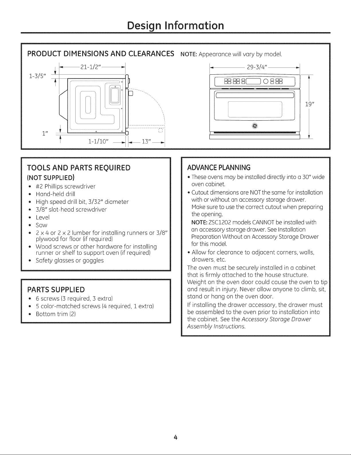
PRODUCT DIMENSIONS AND CLEARANCES
_21-1/2"
i-3/5"
f
J
\
\
irt
i-i/io"
TOOLS AND PARTS REOUIRED
(NOT SUPPLIED}
• #2 Phillips screwdriver
• Hand-held drill
High speed drill bit, 3/32" diameter
• 3/8" slot-head screwdriver
Level
• Saw
2 x 4 or 2 x 2 lumber for installing runners or 3/8"
plywood for floor (if required)
Wood screws or other hardware for installing
runner or shelf to support oven (if required)
Safety glasses or goggles
PARTS SUPPLIED
6 screws (3 required, 3 extra)
5 color-matched screws (4 required, 1extra)
Bottom trim (2)
NOTE: Appearance will vary by model.
_, 29-3/4" _-
ooooooB 0Boo}oo oo
ADVANCE PLANNING
These ovens may be installed directly into a 30" wide
oven cabinet.
Cutout dimensions are NOTthe same for installation
with or without an accessory storage drawer.
Make sure to use the correct cutout when preparing
the opening.
NOTE:ZSC1202 models CANNOT be installed with
an accessory storage drawer. See Installation
Preparation Without an Accessory Storage Drawer
for this model.
Allow for clearance to adjacent corners, walls,
drawers, etc.
The oven must be securely installed in a cabinet
that is firmly attached to the house structure.
Weight on the oven door could cause the oven to tip
and result in injury. Never allow anyone to climb, sit,
stand or hang on the oven door.
If installing the drawer accessory, the drawer must
be assembled to the oven prior to installation into
the cabinet. See the Accessory Storage Drawer
Assembly Instructions.
4
Page 5
Installation Preparation
ELECTRICAL REQUIREMENTS
Single Advantium 120 Installation:
This product requires a i20-volt, 60 Hz, 1S-amp
circuit and draws 1.8 kilowatts. This product must be
connected to a supply circuit of the proper voltage
and frequency.
• Wire size must conform to the requirements of the
National Electrical Code or the prevailing local code
for this kilowatt rating.
The power supply cord and plug should be brought
to a separate 15 or 20 ampere branch circuit single
grounded receptacle. The outlet box should be
located within reach of the 48" power cord.
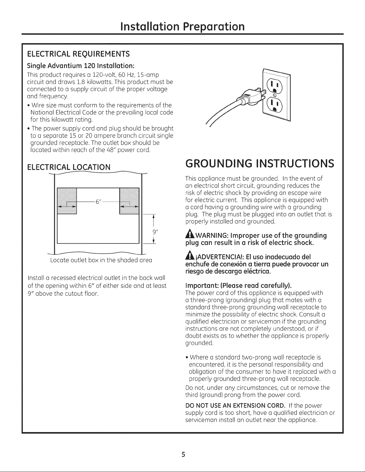
ELECTRICAL LOCATION
6n
t
9"
Locate outlet box in the shaded area
Install a recessed electrical outlet in the back wall
of the opening within 6" of either side and at least
9" above the cutout floor.
GROUNDING INSTRUCTIONS
This appliance must be grounded. In the event of
an electrical short circuit, grounding reduces the
risk of electric shock by providing an escape wire
for electric current. This appliance is equipped with
a cord having a grounding wire with a grounding
plug. The plug must be plugged into an outlet that is
properly installed and grounded.
_ILWARNING: Improper use of the grounding
plug can result in a risk of electric shock.
_iADVERTENCIAh El usa inadecuado del
enchufe de conexi6n a tierra puede provocar un
riesgo de descarga el_ctrica.
Important: (Please read carefully}.
The power cord of this appliance is equipped with
a three-prong (grounding) plug that mates with a
standard three-prong grounding wall receptacle to
minimize the possibility of electric shock. Consult a
qualified electrician or serviceman if the grounding
instructions are not completely understood, or if
doubt exists as to whether the appliance is properly
grounded.
• Where a standard two-prong wall receptacle is
encountered, it is the personal responsibility and
obligation of the consumer to have it replaced with a
properly grounded three-prong wall receptacle.
Do not, under any circumstances, cut or remove the
third (ground) prong from the power cord.
DO NOT USEAN EXTENSION CORD. If the power
supply cord is too short, have a qualified electrician or
serviceman install an outlet near the appliance.
5
Page 6
Installation Preparation
PreparationWITHOUTanAccessoryStorage
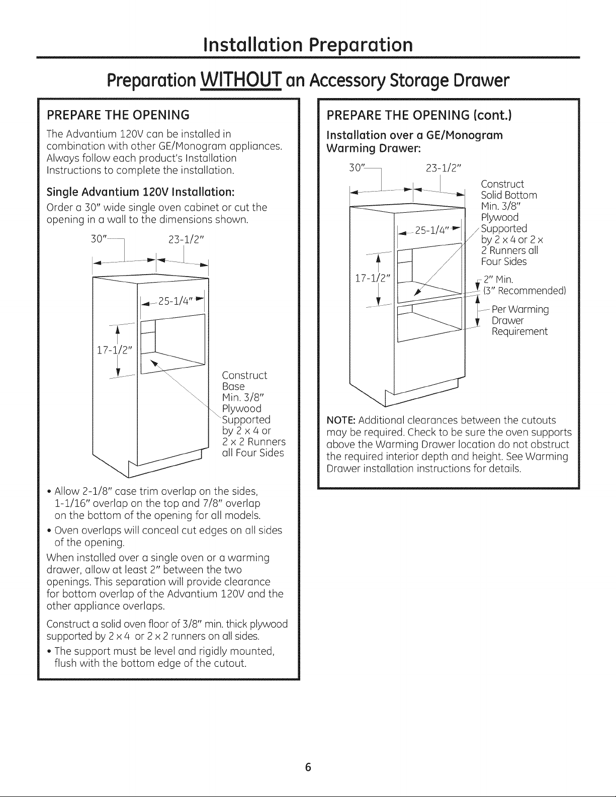
PREPARE THE OPENING
The Advantium 120V can be installed in
combination with other GE/Monogram appliances.
Always follow each product's Installation
Instructions to complete the installation.
Single Advantium 120V Installation:
Order a 30" wide single oven cabinet or cut the
opening in a wall to the dimensions shown.
Drawer
PREPARE THE OPENING {cont.)
Installation over a GE/Honogram
Warming Drawer:
23-1/2"
Construct
Solid Bottom
Min. 3/8"
Plywood
25_i/4"_"-
17-1/2"
Supported
by2x4or2x
2 Runners oil
Four Sides
-2" Min.
(3" Recommended)
Drawer
Requirement
Worming
Construct
Bose
Min. 3/8"
_Plywood
Supported
by2x4or
2 x 2 Runners
oil Four Sides
• Allow 2-1/8" case trim overlap on the sides,
1-1/16" overlap on the top and 7/8" overlap
on the bottom of the opening for all models.
• Oven overlaps will conceal cut edges on all sides
of the opening.
When installed over a single oven or a warming
drawer, allow at least 2" between the two
openings. This separation will provide clearance
for bottom overlap of the Advantium 120V and the
other appliance overlaps.
Construct a solid oven floor of 3/8" min. thick plywood
supported by 2 x 4 or 2 x 2 runners on all sides.
The support must be level and rigidly mounted,
flush with the bottom edge of the cutout.
NOTE: Additional clearances between the cutouts
may be required. Check to be sure the oven supports
above the Warming Drawer locution do not obstruct
the required interior depth and height. See Worming
Drawer installation instructions for details.
Page 7
Installation Preparation
PreparationWITHOUTanAccessoryStorageDrawer
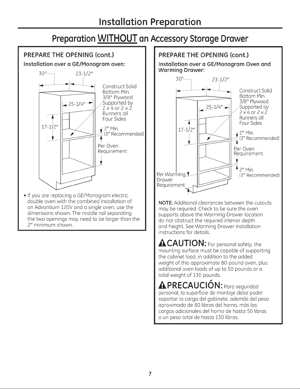
PREPARE THE OPENING (cont.)
Installationover a GE/Monogram oven:
2]-i/2"
Construct Solid
Bottom Nin.
3/8" Plywood
_Supported by
2x4or2x2
Runners all
Four Sides
17-i/2"
,, If you are replacing u GE/Honogrum electric
double oven with the combined installation of
an Advantium 120V and a single oven, use the
dimensions shown. The middle rail separating
the two openings may need to be larger than the
2" minimum shown.
2" Min.
Recommended)
Per Oven
Requirement
PREPARE THE OPENING (cont.)
Installation over a GE/Honogram Oven and
Warming Drawer:
23-1/2"
Construct Solid
Bottom Hin.
3/8" Plywood
Supported by
_2x4or2x2
Runners all
Four Sides
....2" Min.
(3" Recommended)
Per Oven
Requirement
Per
Drawer
Requirement
NOTE: Additional clearances between the cutouts
may be required. Check to be sure the oven
supports above the Warming Drawer location
do not obstruct the required interior depth
and height. See Warming Drawer installation
instructions for details.
Min.
(3" Recommended)
ACAUTION: Forpersonalsafety, the
mounting surface must be capable of supporting
the cabinet load, in addition to the added
weight of this approximate 80-pound oven, plus
additional oven loads of up to S0 pounds or a
total weight of 130 pounds.
APRECAUCION: Paraseguridad
personal, la superficie de montaje debe poder
soportar la carga del gabinete, adem6s del peso
aproximado de 80 libras del homo, m6s las
cargas adicionales del homo de hasta SOlibras
o un peso total de hasta 130 libras.
Page 8
Installation Preparation
Preparation WITHOUT an AccessoryStorage Drawer
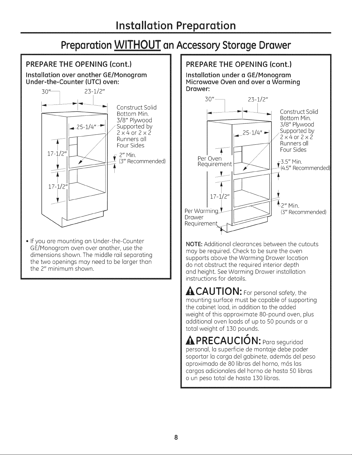
PREPARE THE OPENING (cont.)
Installation over another GE/Monogram
Under-the-Counter IUTC) oven:
Construct Solid
Bottom Min.
]/8" Plywood
_ Supported by
2x4or2x2
Runners oil
Four Sides
2" Min.
(3" Recommended)
PREPARE THE OPENING (cont.)
Installation under a GE/Monogram
Microwave Oven and over a Warming
Drawer:
Construct Solid
Bottom Min.
]/8" Plywood
Supported by
/2x4or2x2
Runners all
Four Sides
Per Oven
Recuirement
4.5" Recommended
2" Hin.
(3" Recommended)
Min.
• If you are mounting on Under-the-Counter
GE/Honogram oven over another, use the
dimensions shown. The middle rail separating
the two openings may need to be larger than
the 2" minimum shown.
NOTE: Additional clearances between the cutouts
may be required. Check to be sure the oven
supports above the Warming Drawer locution
do not obstruct the required interior depth
and height. See Warming Drawer installation
instructions for details.
ACAUTION: Forpersonal safety, the
mounting surface must be capable of supporting
the cabinet load, in addition to the added
weight of this approximate 80-pound oven, plus
additional oven loads of up to 50 pounds or o
total weight of 130 pounds.
APRECAUCION: Paraseguridod
personal, la superficie de montaje debe poder
soportor la cargo del gobinete, adem6s del peso
aproximado de 80 libras del homo, m6s los
cargos odicionoles del horno de hosto 50 libros
o un peso total de hosto 130 libros.
Page 9
Installation Preparation
PreparationWITHOUTanAccessoryStorageDrawer
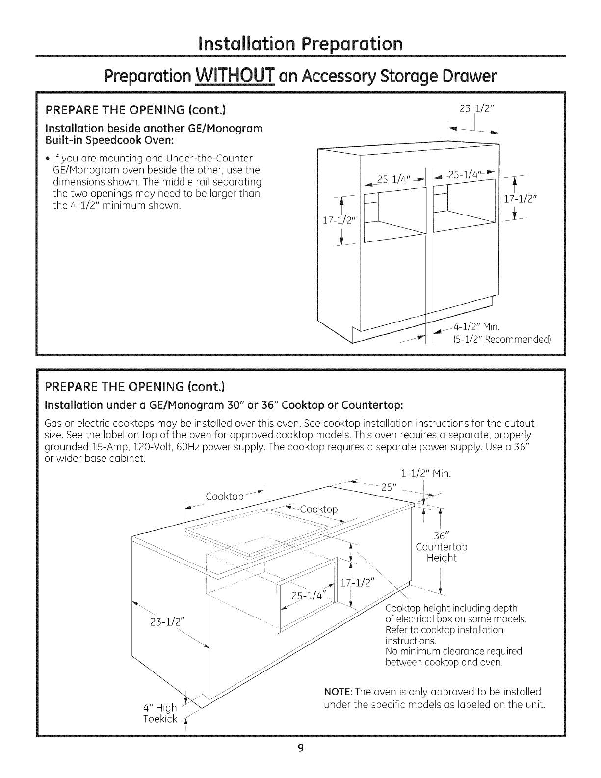
PREPARE THE OPENING (cont.)
Installation beside another GE/Plonogram
Built-in Speedcook Oven:
• If you ore mounting one Under-the-Counter
GE/Honogram oven beside the other, use the
dimensions shown. The middle rail separating
the two openings may need to be larger than
the 4-1/2" minimum shown.
PREPARE THE OPENING icont.)
23-1/2"
17-1/2"
17-1/2"
J4-i/2" Hin.
(5-i/2" Recommended)
Installation under a GE/Monogram 30" or 36" Cooktop or Countertop:
Gas or electric cooktops may be installed over this oven. See cooktop installation instructions for the cutout
size. See the label on top of the oven for approved cooktop models. This oven requires a separate, properly
grounded 15-Amp, 120-Volt, 60Hz Dower supply. The cooktop requires a separate power supply. Use a 36"
or wider base cabinet.
i- i/2" Hin.
i
36"
Countertop
Height
23-1/2"
Cookto
J
17-1/2"
Cooktop height including depth
of electrical box on some models.
Refer to cooktop installation
instructions.
No minimum cleorance required
between cooktop and oven.
4" High
Toekick
NOTE: The oven is only approved to be installed
under the specific models as labeled on the unit.
Page 10
Installation Preparation
PreparationWIT____HHan Accessory Storage Drawer
NOTE:MODELZSCI201 CAN ONLYBEINSTALLEDWITHAN ACCESSORYSTORAGEDRAWERIFINSTALLEDABOVE36-3/4".
MODELZSC1202CANNOTBEINSTALLEDWITH AN ACCESSORYSTORAGEDRAWER.SEEINSTALLATIONPREPARATIONWITHOUT
ANACCESSORYSTORAGEDRAWERFORTHIS MODEL.
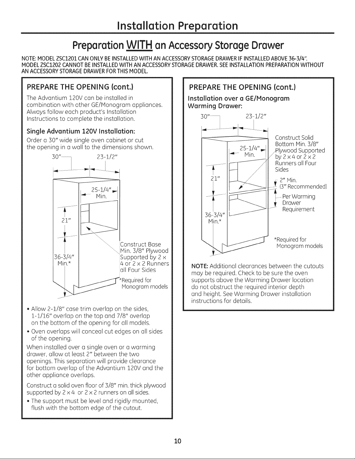
PREPARE THE OPENING (cont.}
The Advantium &20V can be installed in
combination with other GE/Monogram appliances.
Always follow each product's Installation
Instructions to complete the installation.
Single Advantium 120V Installation:
Order a 30" wide single oven cabinet or cut
the opening in a wall to the dimensions shown.
25-1/4"_
4k-- Hin.
21"
\\\
\
Construct Bose
\\
" Min. 3/8" Plywood
Supported by 2 x
4 or 2 x 2 Runners
all Four Sides
uired for
Monogram models
• Allow 2-1/8" case trim overlap on the sides,
1-1/16" overlap on the top and 7/8" overlap
on the bottom of the opening for all models.
• Oven overlaps will conceal cut edges on all sides
of the opening.
When installed over a single oven or a warming
drawer, allow at least 2" between the two
openings. This separation will provide clearance
for bottom overlap of the Advantium 120V and the
other appliance overlaps.
PREPARE THE OPENING (cont.}
Installation over a GE/Monogram
Warming Drawer:
23-1/2"
Construct Solid
Bottom Min. 3/8"
/Plywood Supported
by2x4or2x2
Runners all Four
Sides
2" Min.
(3" Recommended)
Warming
Drawer
Requirement
*Required for
Monogram models
NOTE: Additional clearances between the cutouts
may be required. Check to be sure the oven
supports above the Warming Drawer location
do not obstruct the required interior depth
and height. See Warming Drawer installation
instructions for details.
Construct a solid oven floor of 3/8" min. thick plywood
supported by 2 x 4 or 2 x 2 runners on all sides.
The support must be level and rigidly mounted,
flush with the bottom edge of the cutout.
lO
Page 11
Installation Preparation
PreparationWIT____HHan Accessory Storage Drawer
NOTE:MODELZSC1201CANONLYBEINSTALLEDWITHAN ACCESSORYSTORAGEDRAWERIFINSTALLEDABOVE36-3/4".
MODELZSC1202CANNOTBEINSTALLEDWITH AN ACCESSORYSTORAGEDRAWER.SEEINSTALLATIONPREPARATIONWITHOUT
ANACCESSORYSTORAGEDRAWERFORTHIS MODEL.
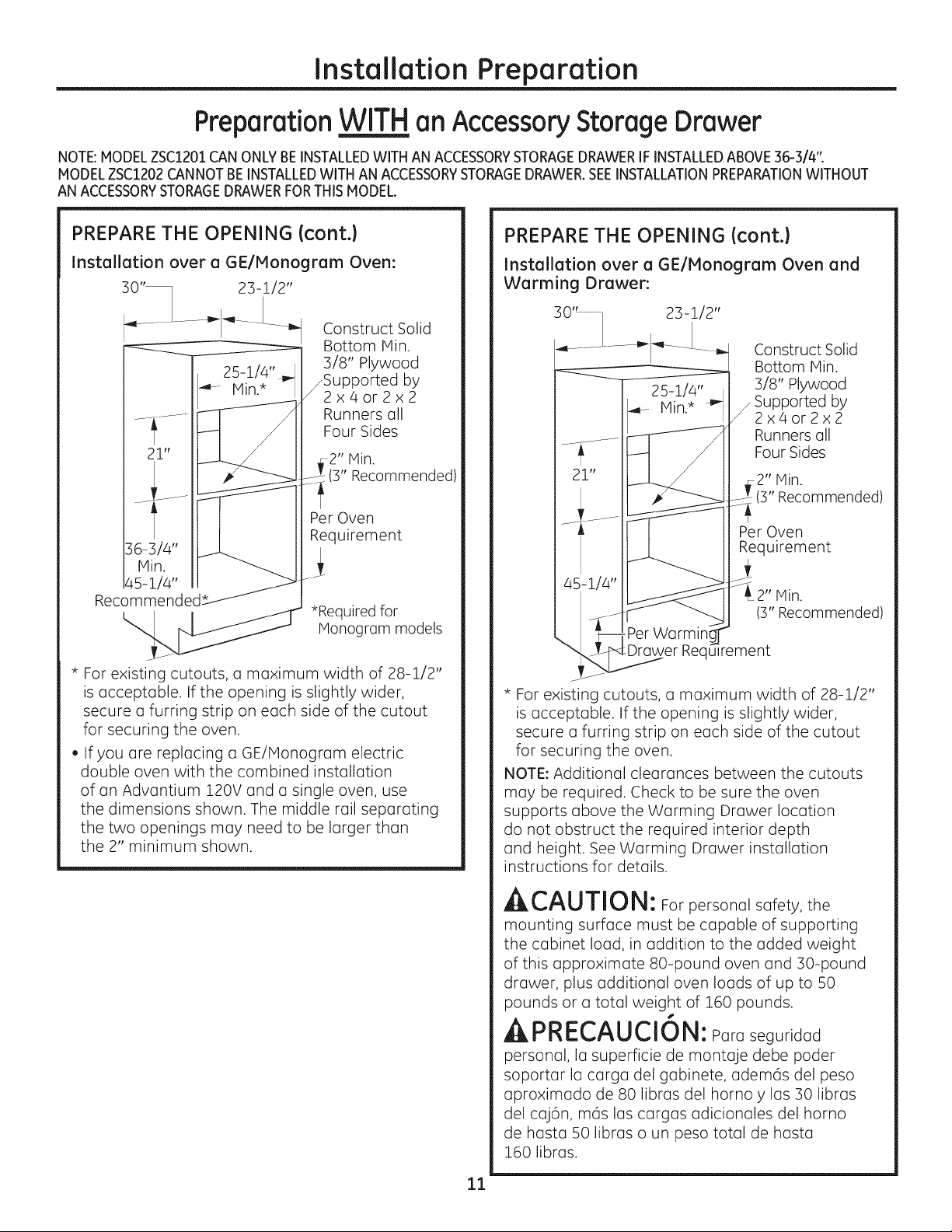
PREPARE THE OPENING (cont.)
Installation over a GE/Monogram Oven:
Construct Solid
Bottom Hin.
3/8" Plywood
_Supported by
2x4or2x2
Runners oll
Four Sides
21"
Hin.
tt
Recommended
* For existing cutouts, o maximum width of 28-1/2"
is acceptable. If the opening is slightly wider,
secure mfurring strip on each side of the cutout
for securing the oven.
. If you ore replacing a GE/Honogram electric
double oven with the combined instollotion
of on Advontium 120V and o single oven, use
the dimensions shown. The middle rail separating
the two openings may need to be larger than
the 2" minimum shown.
2" Min.
(B" Recommended)
Per Oven
Requirement
*Required for
Monogrmm models
PREPARE THE OPENING (cont.)
Installation over a GE/Monogram Oven and
Warming Drawer:
Construct Solid
Bottom Hin.
3/8" Plywood
_ Supported by
2x4or2x2
Runners all
Four Sides
2" Min.
(3" Recommended)
Per Oven
Requirement
Hin.
(3" Recommended)
:Drower Requirement
* For existing cutouts, o moximum width of 28-1/2"
is occeptoble. If the opening is slightly wider,
secure o furring strip on eoch side of the cutout
for securing the oven.
NOTE: Additionol cleoronces between the cutouts
moy be required. Check to be sure the oven
supports obove the Worming Drower Iocotion
do not obstruct the required interior depth
ond height. See Worming Drower instollotion
instructions for detoils.
ACAUTION: Forpersonol sofety, the
mounting surfoce must be capable of supporting
the cabinet loud, in addition to the added weight
of this approximate 80-pound oven and 30-pound
drawer, plus additional oven loads of up to 50
pounds or o total weight of 160 pounds.
APRECAUCION: Poroseguridod
personal, Io superficie de montuje debe poder
soportor Io cargo del gobinete, odem6s del peso
uproximudo de 80 librus del homoy los B0 libros
del cuj6n, m6s los cargos udicionules del homo
de basra 50 libros o un peso total de basra
160 libros.
11
Page 12
Installation Preparation
PreparationWIT______H_Han Accessory Storage Drawer
NOTE:MODELZSC1201CANONLYBEINSTALLEDWITH AN ACCESSORYSTORAGEDRAWERIFINSTALLEDABOVE36-3/4%
MODELZSC1202CANNOTBEINSTALLEDWITHAN ACCESSORYSTORAGEDRAWER.SEEINSTALLATIONPREPARATIONWITHOUT
ANACCESSORYSTORAGEDRAWERFORTHIS MODEL.
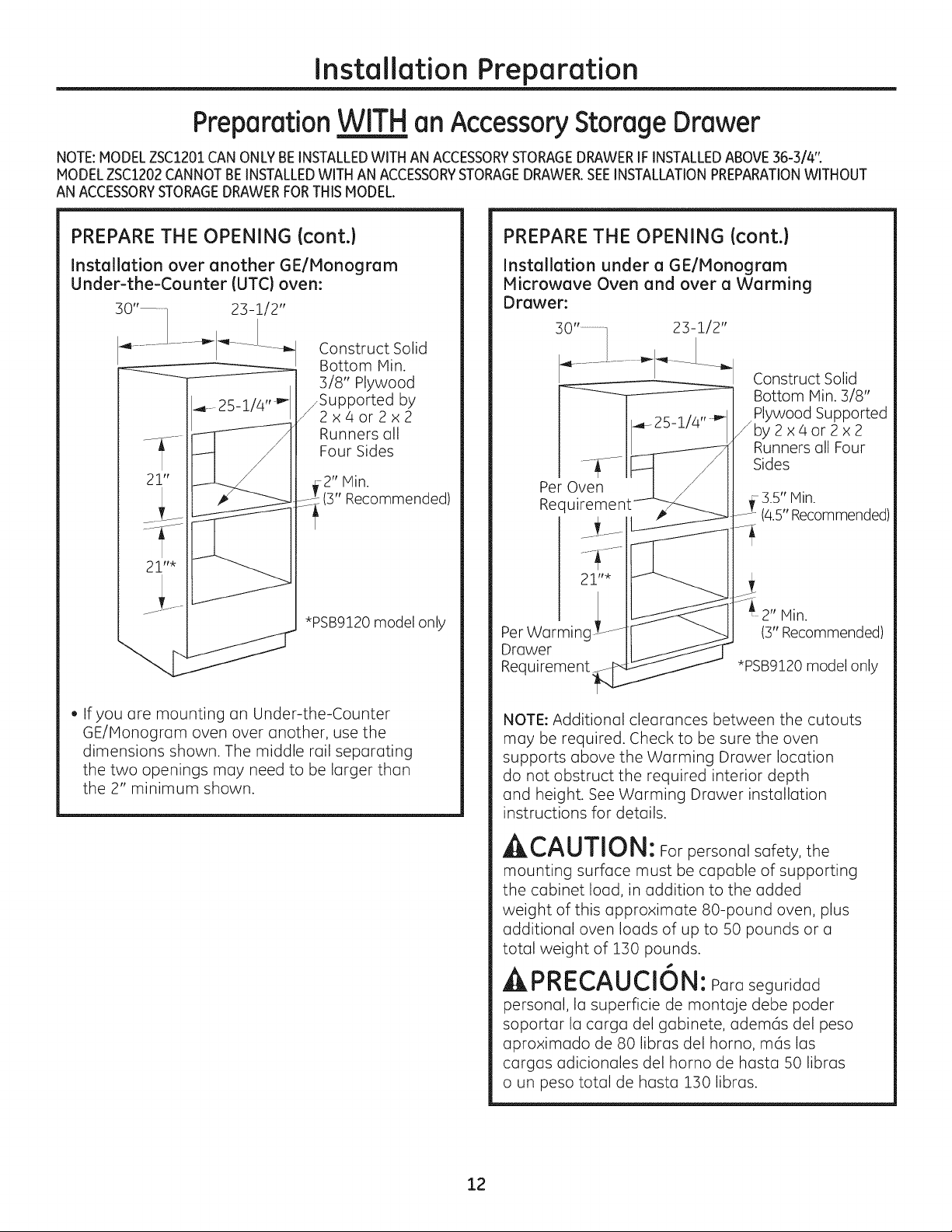
PREPARE THE OPENING Icont.}
Installation over another GEIMonogram
Under-the-Counter IUTC) oven:
23-1/2"
Construct Solid
Bottom Hin.
]/8" Plywood
_Supported by
2x4or2x2
Runners GII
Four Sides
2" Min.
(3" Recommended)
*PSB9120 model only
PREPARE THE OPENING Icont.}
Installation under a GE/Monogram
Microwave Oven and over a Warming
Drawer:
Construct Solid
Bottom Hin. 3/8"
/ Plywood Supported
by2x4or2x2
Runners all Four
Sides
Per Oven
Re(
Per Warminc
Drawer
Requirement
3.5" Min.
(4.5"Recommended)
2" Min.
(3" Recommended)
*PSB9120 model only
• Ifyou are mounting an Under-the-Counter
GE/Honogram oven over another, use the
dimensions shown. The middle rail separating
the two openings may need to be larger than
the 2" minimum shown.
NOTE: Additional clearances between the cutouts
may be required. Check to be sure the oven
supports above the Warming Drawer location
do not obstruct the required interior depth
and height. See Warming Drawer installation
instructions for details.
^ CAUTION: Forpersonolsofety, the
mounting surface must be capable of supporting
the cabinet loud, in addition to the added
weight of this approximate 80-pound oven, plus
additional oven loads of up to 50 pounds or u
total weight of 130 pounds.
APRECAUCION: Poroseguridod
personal, Io superficie de montoje debe poder
soportor I° cargo del gabinete, adem(ls del peso
aproximado de 80 libros del homo, m_s los
cargas odicionales del homo de hast° 50 libros
o un peso totol de host° 130 libros.
12
Page 13

Installation Preparation
PreparationWIT_____HHan Accessory Storage Drawer
NOTE:MODELZSC1201CANONLYBEINSTALLEDWITH AN ACCESSORYSTORAGEDRAWERIFINSTALLEDABOVE36-3/4%
MODELZSC1202CANNOTBEINSTALLEDWITHAN ACCESSORYSTORAGEDRAWER.SEEINSTALLATIONPREPARATIONWITHOUT
ANACCESSORYSTORAGEDRAWERFORTHIS MODEL.
PREPARE THE OPENING Icont.}
Installation beside another GE/Monogram
Built-in Speedcook Oven:
• If you ore mounting one Under-the-Counter GE/
Honogrom oven beside the other, use
the dimensions shown. The middle rail separating
the two openings may need to be larger than
the 4-1/2" minimum shown.
PREPARE THE OPENING (cont.}
23-1/2"
21"
I .....
21"
Installation under a GE Profile 30" or 36" Cooktop or Countertop:
Gas or electric cooktops moy be installed
over this oven. See cooktop instollution
instructions for the cutout size. See the
label on top of the oven for approved
cooktop models. This oven requires
a separate, properly
grounded 15-Amp,
120-Volt, 60Hz power
supply. The cooktop
requires o separate power
supply. Use o 36" or wider
bose cabinet.
23-1/2"
IMPORTANT:
For PSB9120 model only.
The Honogrom oven
and drawer combination
cannot be installed below
o countertop.
4" High z,
Toekick¢
Cookto
NOTE: The oven is only approved to be instolled
under the specific models as labeled on the unit.
36"
Countertop
Height
\
p height including
depth of electricul box on
some models. Refer to cooktop
inst(]llotion instructions.
No minimum cleoronce
required between cooktop @nd
oven.
13
Page 14

Installation Instructions
REMOVE THE PACKAGING AND PARTS
• Remove oil packing material and tope.
Locate ports package containing mounting screws.
• Remove the oven from the carton. Do not lift unit
by handle or conduit. Two people are required to lift
this oven.
• Open the door and remove any packaging in oven.
Rack
Owner's
Manual
Owner's Manual
Cook Book
Installetion
Instructions
Installation
Instructions
Cooking
Guide
Cook Book Cooking Guide
Glass Tray Turntable Ring
ACAUTION: installing theAdvantium
120V Oven below 36% you must use the plastic
bottom trim due to burn risk to children. The
plastic trim acts as insulation and will help prevent
burns to children from hot surfaces.
s
APRECAUCION: Sivaa instalar el
homo Advantium de 120V debajo de B6", usted
debe utilizar el reborde inferior pl6stico debido al
riesgo de quemaduras para los ni_os. El reborde
pl6stico act0a coma aislante y evitar6 que los
ni_os sufran quemaduras provocadas par los
superficies calientes.
1 J
Bottom Trim - Plastic
Bottom Trim - Metal
MetalTrays (2)
6 Brass Screws
(3 required, 3 extra)
5 Color-Matched Screws
(4 required, ! extra)
IMPORTANT: If installing the Advantium 120V Oven
with an accessory storage drawer, read the storage
drawer assembly instructions to assemble the
products together before proceeding to Step 2.
14
Page 15

Installation Instructions
[_] DOOR TRIM REMOVAL FOR ABOVE
36" INSTALLATION ONLY
If installing the Advantium 120V Oven above 36"
from the floor, you may remove the plastic trim
from the bottom of the door for esthetic purposes
if desi red.
ACAUTION: installing theAdvantium
120V Oven below 36", do not remove the
plastic door trim due to burn risk to children.
The plastic trim acts as insulation and will help
prevent burns to children from hot surfaces.
_LI_I_I=LJ"_LJ _..I UI_ : Si va a instolar el
horno Advantium de 120V debajo de 36", usted
no debe quitar el reborde pldstico de la puerta
debido al riesgo de quemaduras para los
ni_os. El reborde pldstico actOa coma aislante
y evitar(l que los ni_os sufran quemaduras
provocadas par las superficies calientes.
,, If installing above 36", remove the 3 screws that
secure the plastic trim to the bottom of the door.
• Discard plastic trim. Replace screws.
I
[
i-_ SLIDE THE OVEN INTO THE CUTOUT
,ACAUTION: Twopeoplearerequiredto
lift the oven into the opening. Grasp the bottom
at front and rear. DO NOT USETHE HANDLE TO LIFT
THE OVEN. DAMAGE WILL OCCUR.
A PRECAUCION:Se necesitan dos
personas para levantar el homo basra la abertura.
T6melo de la porte inferior desde el frente y la porte
trasera. NO USE LA IVlANUA PARA LEVANTAR EL
HORNO. SE PRODUCIRAN DA--OS.
,, Lift and hold the oven at the front of the opening.
Hold the oven at an angle and plug in the power
cord.
,,,Carefully, slide the oven into the cabinet part
way. Leave the oven a few inches forward of
the cabinet frame.
Check to be sure the power cord is not trapped
under the oven or along the sides of the oven.
15
Page 16

Installation Instructions
INSTALL BOTTOM TRIM
ACAUTION: Ifinstalling theAdvantium
120V Oven below 36", you must use the plastic
bottom trim due to burn risk to children. The plastic
trim acts as insulation and will help prevent burns
to children from hot surfaces.
PRE:CAU ClaN: siveeinstolorelhomo
Adventium de !20V debejo de 36", usted debe utilizer
el reborde inferior pl6stico debido el riesgo de
quemodures pore los nihos. Elreborde pl6stico
ect0e come eislente y eviter6 qua los nihos sufren
quemedures provocedes per los superficies celientes.
NOTE: If installing the Advantium 120V Oven
with an accessory storage drawer, the bottom trim
is not required. Proceed to Step 5.
• Installation Below 36", align trim tabs on the plastic
trim to slots in the bottom of the oven.
:m m _ m,
• Installation Above 36", align trim tabs on the plastic
or metal trim to slots in the bottom of the oven.
J
Plastic
t Trim
[_] INSTALL MOUNTING SCREWS
OC] []C] C] C]E]
[ oooo8c oooo ]
Slide the oven the remaining way into the opening
so that the side flanges and control panel are
against the cabinet frame. Make sure that the oven
is centered in the opening.
Open the door, place a turntable tray in the oven
and make sure that the tray in the unit is level.
Drill pilot holes through the side flanges.
Drive the color-matched screws into the side
flanges. It is recommended that the screws
be hand tightened.
If installing oven with an accessory storage
drawer:
Open the drawer.
Drill pilot holes through the side flanges.
Drive color-matched screws into the side flanges.
It is recommended that the screws be hand
tightened.
T _ T T
Plastic
[ :- _" " - I Trim OR
: Metal
[--_ "_--] Trim
Secure the bottom trim to the bottom of the oven
using 3 screws provided.
! J
[_] INSTALL BOTTOM TRIM WITH
ACCESSORY DRAWER
If installing with an accessory drawer, see
installation instructions on page 17 or instructions
that come with the accessory drawer.
NOTE: If installing the Profile Advantium 120V Oven
with an accessory storage drawer, you must use
the Under-the-Counter (UTC)mounting bracket for
the drawer.
If installing the Monogram Advantium integrated
model ZSC1201 above 36", the UTC mounting bracket
for the accessory storage drawer must be used.
| FINALIZE INSTALLATION
• Turn power on atthe source.The interiorlight
should come on when the door isopened.
• Referto Owner's Manual foroperatinginstructions.
16
Page 17

GE Consumer
& Industrial
Appliances
®
As e
Advantium ®
bly In
Built-In
AccessoryStorage
JX2200,JX2201,ZX2201
BEFORE YOU BEGIN
Readthese instructions completely and carefully.
Readthe Installation Instructions for the Advantium
120V or 240V oven completely and carefully for cutout
dimensions and step-by-step instructions.
IMPORTANT- Savetheseinstructionsfor
local inspector's use.
IMPORTANT- Observeallgoverningcodes
and ordinances.
• NOTE TO INSTALLER: Besure to leave these
instructions with the Consumer.
• NOTE TO CONSUMER: Keep these instructions with
your Advantium 120V or 240V Oven Owner's Manual
for future reference.
• SKILL LEVEL: Installation of this appliance requires
basic mechanical skills.
tr ct
Drawer
MODELS AVAILABLE
Profile Models:
JX2200BB-Black
JX2201SS-Stainless Steel
Monogram Models:
ZX2201SS-Stainless Steel (for installation above 36" only)
NOTE: Advantium 240V model ZSC2202SS and
Advantium 120V model ZSC1202 CANNOT be
installed with an accessory storage drawer. See
Installation Preparation Without an Accessory Storage
Drawer in the Installation Instructions for these models.
PRODUCT DIMENSIONS AND CLEARANCES
•COMPLETION TIME: One hour with the installation
of an Advantium 120V or 240V oven.
• Proper installation isthe responsibility of the installer.
Product failure due to improper installation is not
covered under the Warranty. Seethe Advantium
120V or 240V Oven Owner's Hanual for warranty
information.
_ J_t 5"
Allow 15" clearance
when fully open
NOTE: Appearance will vary by model.
TOOLS REOUIRED
, #2 Phillips screwdriver
PARTS SUPPLIED
. 2 SideSupports
. Screws(8)
. Screws(color-matched)(5)
Under-the-Counter Mounting Bracket(1)
17
Page 18

ASSEMBLY TO ADVANTIUM BUILT-IN SPEEDCOOK OVEN
| REMOVE PACKAGING AND PARTS
• Remove the drewer from the certon.
• Remove ell pecking materiel end tope.
• Open the drewer end remove eny ports inside.
• Locete ports.
Assemblg
Instructions
Side Supports (2)
Assembly Instructions
Under-the-Counter
(UTC)Mounting Bracket
Screws Color-Matched
(6required, Screws
2 extra) (4 required,
i extra)
ASSEMBLING THE OVEN TO DRAWER
[]
Place storage drawer on a surface with
the front of drawer hanging over the edge
of the surface. Not placing the front edge
of drawer over the edge of the surface may
result in damage to the drewer since the front
edge of drower bongs below the bottom
of drower.
Place the oven on top of the storage drawer.
B]
Hake sure that the back and sides of the oven
align with the back and sides of drawer.
NOTE: The bottom of the oven side flanges will
sit directly in front of the top of the storoge
drower side flonges.
[_ UNDER-THE-COUNTER (UTC}
MOUNTING BRACKET INSTALLATION
NOTE: For UTC models PSB9120 end ZSC1201 only.
Open the occessory drower so you hove
occess to the top brocket.
Remove the three screws securing the top
brocket.
r_ Install the new UTC mounting brocket using
the screws removed previously.
r_ Close the drawer and proceed with the
installation.
18
Page 19

ASSEMBLY TO ADVANTIUM BUILT-IN SPEEDCOOK OVEN
ASSEMBLING THE OVEN TO DRAWER
Icont.)
r_ Remove the front two bottom screws on each
side of the oven and the top center screw on
each side of the storage drawer.
El
H
H
H
H
H
H
H
D
Place the side supports into the tabs on the
drawer and secure using the screws supplied
and the screws removed in Step C.
Side
Support
120v only f
B] The oven and storage drawer assembly is now
ready to be installed. Return to the Advantium
120V or 240V Built-In SpeedCook Oven
Installation Instructions to complete
the installation.
19
Page 20

Printed in Korea
NOTE: While performing instollotions described in this book,
sofety glosses or goggles should be worn.
NOTE: Product improvement is o continuing endeovor ot
GeneroJ Electric. Therefore, moteriols, oppeoronce ond
specificotions ore subject to chonge without notice.
GE Appliances & Lighting
Appliances
General Electric Company
Louisville, KY40225
GEAppliances.com
Page 21

®
Instr
¢¢ e
de instalaci6n
Hornos de cocci6n
r6pida empotrados
de 120V Advantium ®
PSB9120DF
PSB9120SF
ZSC1201
ZSC1202
49-40688-!
iVIFL59060909 l
08-13 GE
Page 22

Informaci6n de seguridad
ANTES DE COHENZAR
Lea estas instrucdones par completo y con
detenimiento.
IH PORTANTE - Guardeestasinstrucciones
para el usa de inspectores locales.
IMPORTANTE -Cumplacontodoslos
c6digos y ordenanzas vigentes.
• Nota al instalador- AsegGrese de dejar estas
instrucciones con el Consumidor.
• Nota al consumidor- Mantenga estas
instrucciones con el Manual del Propietario para
referencia futura.
• Nivel de capacidad - La instalaci6n de este
aparato requiere capacidades mecanicas y el6ctricas
bc_sicas.
• Tiempo de finalizaci6n - 1 hora.
• Elinstalador tiene la responsabilidad de efectuar una
instalaci6n adecuada, La Garant[a no cubre las fallas
del producto debido a una instalaci6n incorrecta. Vet
el Manual del Propietario para informaci6n sabre la
garant[a.
NOTA:Estehomo s61opuede instalarsedebajo
de losmodelos especFicoscoma seindica en la etiqueta
de esta unidad.
CONTENIDOS
Informaci6n de dise_o
Modelos disponibles ..............................................................2
Dimensiones y distancias del producto .......................3
Herramientas y piezas requeridas ..................................3
Piezas provistas .......................................................................3
Planificaci6n previa ................................................................3
Preparaci6n para la instalaci6n
Requisitos el6ctricos ..............................................................4
Preparaci6n de la abertura (instalaci6n sin un
caj6n de almacenamiento de accesorios) .........5-8
Preparaci6n de la abertura (instalaci6n con un
caj6n de almacenamiento de accesorios) .......9-12
Instalaci6n bajo una estufa de 36"..............................12
Instrucciones de instalaci6n
Paso 1,Quite el empaque y los piezas......................13
Paso 2, Remoci6n del reborde de la
puerta s61opara instalaciones
sabre S6".................................................................14
Paso 3, Desliceel homo dentro de la abertura .....14
Paso 4, Instale el reborde inferior ................................15
Paso 5, Instale el reborde inferior con el caj6n
de accesorios ........................................................15
Paso 6, Instalelostomillosde montaje..................................15
paso 7, Finalice la instalaci6n ........................................15
IMPORTANTE - Utiliceeste horno s61o con
elobjetivopara elque ruecreado. Nunca use el
homo para entibiaro calentaruna habitaci6n.Elusa
prolongado del horno sinuna ventilaci6nadecuada
puede resultarpeligroso.
APRECAUCI6N:
Para seguridad personal, quite el fusible o el interruptor
de circuitos de la vivienda antes de comenzar la
instalaci6n a fin de evitar una lesi6n grave o fatal.
APRECAUCI6N:
Para seguridad personal, la superficie de montaje debe
poder soportar la carga del gabinete, ademc_sde las 80
libras del homo y las :SOlibras del caj6n, mc_slas cargas
adicionales del homo de hasta 50 libras o un peso total
de hasta 160 libras.
APRECAUCI6N:
Siva a instalar el horno Advantium de !20V debajo
de 36%usted debe utilizar el reborde inferior pl6stico
debido al riesgo de quemaduras para los ni_os.
El reborde pl6stico actOa coma aislante y evitard
que los nihos sufran quemaduras provocadas
par las superficies calientes.
APRECAUCI6N:
Siva a instalar el horno Advantium de !20V debajo
de 36%usted no debe quitar el reborde plastico de
la puerta debido al riesgo de quemaduras para los
ni_os. Elreborde pl6stico actL_acoma aislante y evitard
que los niBos sufran quemaduras provocadas par las
superficies calientes.
MODELOS DISPONIBLES
Modelos Profile:
PSB9120DFWW-Blanco*
PSB9120DFBB-Negro
PSB9120SFSS-Acero inoxidable
Modelos Monogram:
ZSC1201SS-Acero inoxidable
ZSC1202SS-Acero inoxidable**
Para este modelo no hay caj6n del mismo color
disponible.
**Esta unidad no puede instalarse con un caj6n
de almacenamiento de accesorios.
Page 23

Informaci6n de dise o
DIMENSIONES Y DISTANCIAS DEL PRODUCTO
_21-1/2"
1-3/5"
{
/
\
in
i-l/lo"_
HERRAMIENTAS Y PIEZAS REQUERIDAS
(NO PROVlSTAS}
• Destornillador de estrella #2
• Perforadora de mano
• Broca para perforadora de alto velocidad
de 5/52" de di6metro
• Destornillador para cabeza ranurada de S/8"
• Nivel
• Sierra
• Madera de 2 x 4 o 2 x 2para instalar guias
o madera terciada de 5/8" para el piso (si se
requiriera)
• Tornillos para madera u otro elemento para
instalar guias o estante para sostener el homo
(si se requiriera)
• Gafas o lentes de seguridad
PIEZAS PROVISTAS
• 6 tornillos (3necesarios, 3 extra)
• 5 tornillos de color (4requeridos, 1 extra)
• Reborde inferior (2)
NOTA: La apariencia varfa segOnel modelo.
-_ 29-314" ,-
_ _ 0 8 o_
( oooo m
19"
PLANIFICACI6N PREVIA
• Estoshornos pueden instalarse directamente dentro
de ungabinete para homo de30" de ancho.
•Las dimensionesdel recorte NOson iguales para la
instalaci6n con o sin uncaj6n de almacenamiento
para accesorios.
AsegQresede utilizar el recortecorrecto cuando
prepare la abertura
NOTA:Losmodelos ZSC1202NOPUEDENinstalarse
con uncaj6n de almacenamiento para accesorios.
Paraeste modelo,ver Preparaci6n para instalaci6n
sin un caj6n dealmacenamiento para accesorios.
• Deje una distancia respecto de rincones, paredes,
cajones adyacentes, etc.
Elhomo debe instalarse bien en un gabinete que
se encuentre firmemente sujeto a la estructura de
la casa. Sise coloca peso sabre la puerto del homo,
6ste puede volcarse y provocar lesiones. Nunca
permita que nadie se suba, siente, pare o cuelgue
de la puerto del horno.
Siva a instalar el accesorio del caj6n, 6ste debe
montarse en el homo antes de la instalaci6n en
el gabinete. Vet los Instrucciones de montaje del
caj6n de almacenamiento de accesorios.
Page 24

Preparaci6n para la instalaci6n
REQUISlTOS ELI_CTRICOS
Instalaci6n de Advantium de 12OV 6nico:
Este producto requiere un circuito de 120 voltios,
60 hercios, 15 amperios y consume 1.8 kilovatios. Este
producto debe conectarse a un circuito de suministro
del voltaje y frecuencia adecuados.
• EltamaBo del cable debe cumplir con los requisitos
del C6digo EI6ctrico Nacional o con el c6digo local
vigente para esta clasificaci6n de kilovatios.
El cable y enchufe de suministro el6ctrico debe
Ilevarse a un recept_culo separado t]nico de circuito
derivado con conexi6n a tierra de 15 o 20 amperios.
La caja de distribuci6n debe ubicarse dentro del
alcance del cable el6ctrico de 48".
UBICACI6N DE LA ELECTRICIDAD
6J_
9"
Ubique la caja de distribuci6n en el
6rea sombreada
Instale un tomacorriente empotrado en la pared
trasera de la abertura dentro de los 6" de cada
lado y por Io menos a 9" por encima del piso
del recorte.
INSTRUCICIONES DE
CONE×ION A TIERRA
Este electrodom6stico deberd estar conectado a
tierra. En caso de que se produzca un cortocircuito,
la conexi6n a tierra reduce el riesgo de descarga
el6ctrica, brindando un cable de escape de la
corriente el@ctrica. Este electrodom6stico estd
equipado con un cable de corriente que posee un
cable de conexi6n a tierra con un enchufe a tierra.
El enchufe se deberd enchufar en un tomacorriente
instalado y conectado a tierra de forma adecuada.
A
ALIADVERTENCIA!: El uso inadecuado del
enchufe de conexi6n a tierra puede provocar un
riesgo de descarga el(_ctrica.
Importante: (Se solicita leer detenidamente).
El cable de corriente de este electrodom6stico
cuenta con un enchufe de 3 clavUas (con cable
a tier[a) que se conecta a un tomacorriente de
pared est6ndar de 3 clavijas para minimizar la
posibil dad de descargas el6ctricas. Consulte
a un electricista calificado o al personal del
s,erviciot6cnico en caso de que las instrucciones
de conexi6n a tierra no se entiendan
cpmpletamente, o sitiene dudas sobre si el
electrodom@sticoest6 conectado a tierra de
forma apropiada.
Para el uso de este artefacto, es responsabilidad
y obligaci6n del consumidor cambiar un
tomacorriente de pared estdndar de dos patas por
uno de tres patas con adecuada conexi6n a tierra.
Bajo ninguna circunstancia corte o quite la tercera
pata (a tierra) del cable el6ctrico.
NO USE UN PROLONGADOR. Si el cable de corriente
es demasiado corto, solicite a un electricista calificado
o al personal del servicio t6cnico que instale un
tomacorriente cerca del electrodom6stico.
4
Page 25

Preparaci6n para la instalaci6n
Preparaa6nSJ Nuncaj6ndealmacenamientodeaccesorios
C6MO PREPARAR LA ABERTURA
ElAdvantium de 120V puede instalarse en
combinaci6n con arras aparatos GE/Monogram.
Siempre siga los Instrucciones de instalaci6n de
coda producto para completar la instalaci6n.
Instalad6n de Advantium de 120V 6nico:
Solicite un gabinete para homo 6nico de 30" de
ancho o carte la abertura en una pared con los
dimensiones indicadas.
Construya
la base de
un minima
de 3/8"
de madera
_terciada
sostenido
par guias de
2x4o2x2
en los cuatro
lados
C6MO PREPARAR LA ABERTURA (cont.)
Instalaci6n sobre un caj6n calentador GEl
Monogram:
Construya una
23-1/2" base s61idade
un minima de
3/8" de madera
terciada
sostenida par
_ galas de 2 x 4
o 2 x 2 en los
cuatro lados
2" minima
(se recomienda 3'!
SegOn los
requisitos
del caj6n
calentador
NOTA: Pueden necesitarse espacios adicionales entre
los recortes. Verifique qua los soportes del homo
sabre la ubicaci6n de caj6n calentador no obstruyan
la profundidad y altura interiores requeridas. Para
mSs detalles, consulte los instrucciones de instalaci6n
del caj6n calentador.
• Oeje una superposici6n del reborde de la caja de
2-1/8", una de i-i/16" sabre la porte superior y
una de 7/8" sabre la porte inferior de la abertura
en todos los modelos.
• Las superposiciones del homo sirven para
esconder los lados cortados sabre todos los
costados de la abertura.
Cuando se instalan sabre un homo Onico o un
caj6n calentador, deje par Io menos 2" entre los
dos aberturas. Esta separaci6n brindar(] un espacio
para la superposici6n superior del Advantium de
120V y los arras superposiciones del aparato.
Construya un pisos61idopara el homo de madera
terciada de un grosor minima de3/8" sostenido par
guiasde 2x 4 o 2x 2 entodos loslados.
Elsoporte debe estar nivelado y bien montado,
alineado con el lado inferior del recorte.
Page 26

Preparaci6n para la instalaci6n
Preparaaon .__ uncaj6ndealmacenamientodeaccesorios
"" SIN
C6MO PREPARAR LA ABERTURA {cont.)
Instalaci6n sabre un homo GE/Monogram:
Construya una
base s61ida de
un minimo de
3/8" de madera
terciada
sostenida por
uias de 2 x 4
o 2 x 2 en los
cuatrolados
17-1/2"
2" minima
(serecomienda 3")
SegQn los
requisitos
delhomo
C6MOPREPARAR LA ABERTURA {cont.)
Instalaci6n sabre un horno y caj6n
calentador GE/Monogram:
Construya una
30' .................I 23-i/2"
17-1/2"
SegOn los
requisitos
del coj6n
calentador
base s61ida de
un minimo de
3/8" de madera
terciada
sostenida par
guias de 2 x 4
o 2 x 2 en los
cuatro lados
2" minima
recomienda 3'!
Seg0n los
requisitos del horno
minima
(se recomienda 3'!
• Si usted est6 reemplazando un horno el6ctrico
doble GE/Monogram con la instalaci6n
combinada de un Advantium de 120V y un horno
Onico, utilice las dimensiones indicadas. El riel
media que separa los dos aberturas puede tener
que ser mayor al minima de 2" indicado.
NOTA: Pueden necesitarse espacios adicionales
entre los recortes. Verifique que los soportes
del homo sobre la ubicaci6n de caj6n calentador
no obstruyan la profundidad y altura interiores
requeridas. Para m6s detalles, consulte las
instrucciones de instalaci6n del caj6n calentador.
A PRECAUCI6N: Paraseguridad
personal, la superficie de montaje debe poder
soportar la carga del gabinete, adem6s del peso
aproximado de 80 libras del homo, m6s las
cargas adicionales del homo de hasta 50 libras
o un peso total de hasta 130 libras.
Page 27

Preparaa6n para la instalaci6n
Preparaa6nSJ Nuncaj6ndealmacenamientodeaccesorios
C6MO PREPARAR LA ABERTURA (cont.)
Instalaci6n sobre otro homo bajo
el mostrador (BEM) GE/Monogram:
30" 1..............._ 23-i/2"
_25-i/4 ''_
Construya una
base s61ida de
un minima de
3/8" de madera
terciada
jsostenida par
guias de 2 x 4
o 2 x 2 en los
cuatro lados
minima
:(se recomienda 3")
C6MO PREPARAR LA ABERTURA (cont.)
Instalaci6n bajo un homo de microondas y
sabre un caj6n calentador GE/Monogram:
Construya una
base s61ida
30" .....................1 _ 23-i/2"
......................... _ ----- __J_______
SegOn losdelI
requisitos
norno _.......
17-1/2"
/
Seg0n los _......
requisitos
del caj6n _
calentador-_,L
de un minima
de 3/8"de
madero
terciada
_sostenida par
guias de 2 x 4
o 2 x 2 en los
cuatro lados
minima
recomienda 4.5")
2 minima
(se recomienda 3")
Si usted estd montando un homo bajo el
mostrador GE/Monogram sabre otto, utilice las
dimensiones indicadas. El riel media que separa
las dos aberturas puede tener que set mayor
al minima de 2" indicado.
NOTA: Pueden necesitarse espacios adicionales
entre los recortes. Verifique que los soportes
del homo sabre la ubicaci6n de caj6n calentador
no obstruyan la profundidad y altura interiores
requeridas. Para m_s detalles, consulte las
instrucciones de instalaci6n del caj6n calentador.
APRECAUCI6N: Para seguridad
personal, la superficie de montaje debe poder
soportar la carga del gabinete, ademas del peso
aproximado de 80 libras del homo, m(_slas
cargas adicionales del homo de hasta 50 libras
o un peso total de hasta 130 libras.
Page 28

Preparaci6n para la instalaci6n
Preparaci6nSN uncaj6ndealmacenamientodeaccesorios
COMO PREPARAR LA ABERTURA (cont.)
Instalaci6n al lado de otro horno de cocci6n
r6pida empotrado GE/Monogram:
• Si usted est6 montando un homo para debojo
del mostrador GE/Monogram al lado de otro,
utilice las dimensiones indicadas. El riel media
que separa las dos aberturas puede tenet que
ser mayor al minima de 4-1/2" indicado.
23-1/2"
/
4-!/2" minima
recomienda 5-!/2")
COMO PREPARAR LA ABERTURA (cont.)
Instalaci6n bajo una estufa o un mostrador de encimera de 30" o 36" GE/Monogram:
Pueden instalarse estufas a gas o el6ctricas sabre este horno. Ver las instrucciones de instalaci6n
de la estufa para el tama_o de la abertura. Ver la etiqueta de la parte superior del horno para consultar
los modelos aprobados de estufa. Este homo requiere un suministro el6ctrico 1-1/2" minima
separado con adecuada conexi6n a tierra de 15 amperios .......... _:
120 voltios y 60 hercios. La estufa
necesita un suministro
el6ctrico separado.
Utilice un gabinete
con una base
de 36" de ancho
o mayor.
17-1/2"
25" _ i
Altura del
mostrador
de encimera
de 36"
Altura de la estufa incluyendo la
profundidad de la cajael6ctrica
en algunos modelos. Consulte las
instrucciones de instalaci6n de la
estufa.
No se requiere un espacio minima
entre la estufa y el homo.
Placa de protecci6n
de 4" de alto
NOTA: Este homo s61o puede instalarse
debajo de los modelos espedficos coma se
indica en la etiqueta de esta unidad.
Page 29

Preparaci6n para la instalaci6n
Preparaci6nCO___NNuncaj6ndealmacenamientodeaccesorios
NOTA:ELMODELOZSC1201SOLOPUEDESERINSTALADOCONUN CAJONDEALMACENAMIENTODEACCESORIOSSISELO INSTALA
PORENCIMADE,36-3/4'I ELMODELOZS,C1202NO PUEDENINSTALARSECONUN CAJONDEALMACENAMIENTODEACCESORJOS.
VERPREPARACIONPARALAINSTALACIONSINUN CAJONDEALMACENAMIENTODEACCESORJOSPARAESTEMODELO.
C6MO PREPARAR LA ABERTURA (cont.)
El Advantium de 120V puede instalarse en
combinaci6n con otros aparatos GE/Monogram.
Siempre siga los Instrucciones de instalaci6n de
coda producto para completar la instalaci6n.
Instalaci6n de Advantium de 120V 6nico:
Solicite un gabinete para homo 6nico de 30" de
ancho o carte Io abertura en una pored con los
dimensiones indicadas.
30" 23-1/2"/
25-1/4"p.
4_-minimo
21"
36-3/4"
minima*
Construya la base
de un minima de
3/8" de madera
terciada sostenida
par gu[as de 2 x
\\\
4 o 2 x 2 en los
\\
\cuatro lados
*Requerido para
modelos Monogram
C6MO PREPARAR LA ABERTURA (cont.)
Instalaci6n sobre un caj6n calentador GE/
Monogram:
23-1/2"
Construya una base
s61ida de un mfnimo
de 3/8" de madera
25-1/4'Ll,.
minima
NOTA: Pueden necesitarse espacios adicionales
entre los recortes. Verifique que los soportes
del homo sabre la ubicaci6n de caj6n calentador
no obstruyan la profundidad y altura interiores
requeridas. Para m6s detalles, consulte los
instrucciones de instalaci6n del coj6n calentador.
terciada sostenida
/
par guias de 2 x 4 o
2 x 2 en los cuatro
lados
2" minima
(serecomienda 3")
Onlos
requisitos
del caj6n
calentador
*Requerido para
modelos Monogram
• Deje una superposici6n del reborde de la caja de
2-1/8", una de 1-1/16" sabre la porte superior y
una de 7/8" sabre la porte inferior de la abertura
en todos los modelos.
• Las superposiciones del homo sirven para
esconder los Iodos cortados sobre todos los
costados de la abertura.
Cuando se instalan sabre un homo 0nico o un
caj6n calentador, deje par Io menos 2" entre los
dos aberturas. Esta separaci6n brindar6 un espacio
para la superposici6n superior del Advantium de
120V y los otras superposiciones del aparato.
Construya un piso s61ido para el homo de madera
terciada de un grosor minima de 3/8" sostenido par
guias de 2 x 4 o 2 x 2 en todos los lados.
• Elsoporte debe estar nivelado y bien montado,
alineado con el lado inferior del recorte.
9
Page 30

Preparaci6n para la instalaci6n
Preparaci6nCO___NNuncaj6ndealmacenamientodeaccesorios
NOTA:ELMODELOZSC1201S6LO PUEDESERINSTALADOCON UNCAJON DEALMACENAMIENTODEACCESORIOSSISELO
INSTALAPORENCIMADE36-3/4". ELMODELOZSC1202NOPUEDEN[NSTALARSECONUN CAJ6N DEALMACENAMIENTODE
ACCESORIOS.VERPREPARACIONPARALAINSTALACIONSINUN CAJONDEALMACENAMIENTODEACCESORIOSPARAESTE
MODELO.
C6MO PREPARAR LA ABERTURA (cont.)
Preparaa6n CON un caj6n de
almacenamiento de accesorios:
Construyauna
base s61ida
de un minimo
de 3/8" de
_ madera
-" minimo* lJsostenida par
---&-- o 2 x 2 en los
/
21"
_6-3/4" requisitos del horno
"ninimo
Se recomienda /._
45-i/4"*
terciada
guias de 2 x 4
cuatro lados
2" minimo
(se recomienda 3")
Seg0n los
*Requerido
pare modelos
Honogram
C6MO PREPARAR LA ABERTURA (cont.)
Instalaci6n sobre un homo y
calentador GE/Monogram:
30".............j _.._23- i/2"/
25-i/4" I
4 minimo*"
21"
SegOn los requisitos
6n calentador
caj6n
Construya una
base s61idade
un minimo de
3/8" de madera
terciada
sostenida por
guias de 2 x 4
o 2 x 2 en los
cuatro lados
2" minimo
:(se recomienda 3'!
SeqOn los requisitos
deFhorno
2" minimo
(se recomienda 3")
* Para recortes existentes, un ancho m6ximo de
28-1/2" es aceptable. Si la abertura es un poco
m6s ancha, coloque un list6n de enrasar en cada
lado del recorte para fijar el homo.
. Si usted est6 reemplazando un homo el6ctrico
doble GE/Monogram con la instalaci6n
combinada de un Advantium de 120Vy un homo
t]nico, utilice las dimensiones indicadas. El riel
medio qua separa las dos aberturas puede tener
qua ser mayor al minimo de 2" indicado.
* Para recortes existentes, un ancho m6ximo de
28-1/2" es aceptable. Si la abertura es un poco
m6s ancha, coloque un list6n de enrasar en cada
lado del recorte para fijar el homo.
NOTA: Pueden necesitarse espacios adicionales
entre los recortes. Verifique que los soportes
del homo sobre la ubicaci6n de caj6n calentador
no obstruyan la profundidad y altura interiores
requeridas. Para m6s detalles, consulte las
instrucciones de instalaci6n del caj6n calentador.
APRECAUCI6N: Para seguridad
personal, la superficie de montaje debe poder
soportar la carga del gabinete, adem6s del peso
aproximado de 80 libras del homoy las 30 libras
del caj6n, m6s las cargas adicionales del homo
de hasta 50 libras o un peso total de hasta
160 libras.
10
Page 31

Preparaci6n para la instalaci6n
Preparaa6nCO___NNuncaj6ndealmacenamientodeaccesorios
NOTA:ELMODELOZSC1201SOLOPUEDESERJNSTALADOCON UN CAJONDEALMACENAMJENTODEACCESORJOSSISELO
INSTALAPORENaMA DE36-3/4': ELF1ODELOZSC120,2NOPUEDEN!NSTALARSECONUN CAJON DEALMACENAMIENTODE
ACCESORJOS.VERPREPARAaONPARALA JNSTALAaONSiN UN CAJON DEALMACENAMJENTODEACCESORJOSPARAESTE
MODELO.
C6MO PREPARAR LA ABERTURA (cont.)
Instalaci6n sabre otto homo bajo el
mostrador (BEM) GE/Monogram:
Construya una
base s61ida de
un minima de
3/8" de madera
terciada
/sostenida par
guias de 2 x 4
o 2 x 2 en los
cuatro lados
2" minima
se recomienda 3")
*S61omodelo
PSB9120
• Si usted estd montando un homo bajo el
mostrador GE/Monogram sabre otro, utilice las
dimensiones indicadas. El riel media que separa
las dos aberturas puede tenet que ser mayor
al minima de 2" indicado.
C6MO PREPARAR LA ABERTURA (cont.)
Instalaci6n bajo un homo de microondas y
sabre un caj6n calentador GE/Monogram:
30" _ 23-1/2"/
4 ............................. _ - ----- _---- --ib-
SegOn los
requisitos
del horno
SegOn los
requisitos
del coj6n
calentador
NOTA: Pueden necesitarse espacios adicionales
entre los recortes. Verifique que los soportes
del homo sabre la ubicaci6n de caj6n calentador
no obstruyan la profundidad y altura interiores
requeridas. Para m6s detalles, consulte las
instrucciones de instalaci6n del caj6n calentador.
Construya una
base s61ida de un
minima de 3/8" de
_madera terciada
sostenida par guias
de2x4o2x2en
los cuatro lados
3.5"minima
(serecomienda 4.5")
2" minima
(se recomienda 3")
*%1o modelo
PSB9120
APRECAUCI6N: Paraseguridad
personal, la superficie de montaje debe poder
soportar la carga del gabinete, ademSs del peso
aproximado de 80 libras del homo, mSs las
cargas adicionales del homo de hasta 50 libras
o un peso total de hasta 130 libras.
11
Page 32

Preparaci6n para la instalaci6n
Preparaci6nCO___NNuncaj6ndealmacenamientodeaccesorios
NOTA:ELF1ODELOZSC1201SOLOPUEDESERINSTALADOCONUN CAJONDEALMAC,ENAMIENTODEACCESORIOSSISELOINSTALA
PORENCIM,ADE36-3/4". ELMODEL,O ZSC1202NO,PUEDENINSTALARSECONUN CAJONDEALMACENAMIENTODEACCESORIOS.VER
PREPARACIONPARALAINSTALACIONSINUN CAJONDEALMACENAMIENTODEACCESORIOSPARAESTEMODELO.
COMO PREPARAR LA ABERTURA (cont.)
Instalaci6n al lado de otro horno de cocci6n
r6pida empotrado GE/Monogram:
• Si usted est6 montando un horno para debajo del
mostrador GE/Monogram al lado de otro, utilice
las dimensiones indicadas. El riel medio que
separa las dos aberturas puede tenet que ser
mayor al minimo de 4-1/2" indicado. Y
COMO PREPARAR LA ABERTURA (cont.)
21"
4 .....
23-1/2"
/
25-i/4""
21"
____t .....
f 4-1/2" minimo
(serecomienda 5-!/2")
Instalaci6n bajo una estufa o un mostrador de encimera de 30" o 36" GE Profile:
Pueden instalarse estufas a gas o el#ctricas sobre este homo. Ver las instrucciones
de instalaci6n de la estufa para el tamaho
de la abertura. Ver la etiqueta de la parte
superior del homo para consultar
los modelos aprobados de estufa.
Este homo requiere un suministro
el#ctrico separado con
adecuada conexi6n
a tierra de 15 amperios,
120 voltios y 60 hercios.
La estufa necesita
un suministro el#ctrico
separado. Utilice
un gabinete con
una base de 36" 23-1/2"
de ancho o mayor.
IMPORTANTE: For PSBgl20
model only. S61opara modelos
Profile. La combinaci6n de homo
y caj6n Monogram no puede instalarse
debajo de Placa de
un mostrador de 4" de alto _/
de encimera. "_
NOTA: Este horno s61o puede instalarse debajo de los modelos
especificos como se indica en la etiqueta de esta unidad.
_:: Estufa
1-1/2" minimo
la profundidad de la caja
el6ctrica en algunos modelos.
Consulte las instrucciones de
instalaci6n de la estufa.
No se requiere un espacio
minimo entre la estufa y el homo.
Altura del
mostrador
de encimera
de 36"
de la estufa incluyendo
12
Page 33

Instruccionesde instalaci6n
rTJ QUITE EL EMPAQUE Y LAS PIEZAS
• Quite todo el material de empaquey la cinta.
• Ubique el paquete de piezas que contiene tornillos
de montaje.
• Quite el homo de la caja de cart6n. No levante
la unidad de la manija o conducto. Se necesitan
dos personas para levantar este homo.
Abra la puerta y quite los elementos de empaque
del interior del homo.
Owner's
Manual
Installation
Instructions
Bandeja
_IL I" KI:I_,h_UI,.,IUI_I: Siva a instalar el
homo Advantium de ]_20Vdebajo de 36", usted
debe utilizar el reborde inferior pl6stico debido al
riesgo de quemaduras para los ni_os. Elreborde
pl6stico act0a como aislante y evitar6 que los
ni_os sufran quemaduras provocadas par las
superficies calientes.
Manual del Instrucciones
Propietario de instalaci6n
Cook Book
Libro de cocina
Gufa de cocci6n
Bandeja de vidrio
Bandejas de metal (2)
I ]
Reborde inferior- Pl6stico
Cooking
Guide
6 tornillos de bronce
(3 requeridos, 3 extra)
Anillo giratorio IMPORTANTE:Siva a instalar el homo Advantium
de 120V con un caj6n de almacenamiento para
accesorios, lea las instrucciones de montaje del
caj6n de almacenamiento para instalar los
productos antes de seguir con el Paso 2.
M
[--q [--
Reborde inferior- Met61ico
5 tornillos de color
(4 requeridos, 1 extra)
13
Page 34

Instruccionesde instalaci6n
REMOCI6N DEL REBORDE
DE LA PUERTA SOLO PARA
INSTALACIONES SOBRE 36"
Si va a instalar el homo Advantium de 120V a una
distancia de 36" del piso, usted puede quitar el
reborde pl6stico de la parte inferior de la puerta
)ara fines est6ticos.
AIL l_Kl_h_U _IUI_I: Siva a instalar el
homo Advantium de :]_20Vdebajo de 36", usted
no debe quitar el reborde pl6stico de la puerta
debido al riesgo de quemaduras para los
ni_os. El reborde pl6stico act0a como aislante
y evitar6 que los ni_os sufran quemaduras
provocadas pot las superficies calientes.
• Si va a realizar la instalaci6n por encima de
las 36", quite los 3 tornillos que fijan el reborde
pl6stico a la parte inferior de la puerta.
• Descarte el reborde pl6stico. Vuelva a colocar
los tornillos.
I
L
DESLICE EL HORNO DENTRO DE
LA ABERTURA
APRECAUCI6N: Senecesitandos
personas para levantar el homo hasta la abertura.
T6melo de la parte inferior desde el frente y la parte
trasera. NO USE LA MANIJA PARA LEVANTAR EL
HORNO. SE PRODUCIRAN DA--OS.
,, Levante y sostenga el homo en el frente de
la abertura. Sostenga el homo en un 6ngulo
y enchufe el cable el6ctrico.
• Con cuidado, deslice el homo dentro del gabinete
a mitad de camino. Deje el homo unas pulgadas
m6s adelante del armaz6n del gabinete.
,, Verifique que el cable el6ctrico no haya
quedado atrapado bajo el homo o a Io largo
de los costados del horno.
14
Page 35

Instruccionesde instalaci6n
F4-] INSTALE EL REBORDE INFERIOR
J
APRI:CAUCION: sivaainstalarelhomo
Advantium de 120V debojo de 36", usted debe utilizar
el reborde inferior pl6stico debido al riesgo de
quemaduras para los nihos. Elreborde pl6stico
actQa como aislante y evitar6 que los nihos sufran
quemaduras provocadas por los superficies calientes.
NOTA: Si vu u instulur el horno Advantium de 120V
con un cuj6n de almacenamiento de accesorios, no
se requiere el reborde inferior. Sigu con el Paso S.
• Instalaci6n debajo de 36", ulinee lus lengOetusdel reborde
pl6stico con lusrunurus de lu purte inferiordel homo.
,_ _
Reborde
'n n M M,
I
• Instalaci6n encima de 36", olinee los lengQetos del
reborde pl6stico o met61ico con Imsrmnurmsde Impmrte
inferior del homo.
iPlastico
/[: o _
Reborde
I Io
__,, ._,__]Reborde
[ ' ' met61ico
pl6stico
_-J INSTALE LOSTORNILLOS DE MONTAJE
Deslice el homo por Iodistancio que folto dentro de
Iooberturo poro que los bridas laterales y el panel de
control se encuentren contra el armaz6n del gabinete.
Verifique que el homo est6 centrado en la abertura.
Abra la puerto, coloque una bandeja giratoria dentro
del horno y asegQrese de que la bandeja de la
unidad est6 nivelada.
o
Perfore orificios piloto a trav6s de los bridas laterales.
o
Introduzca los tornillos de color dentro de los bridas
laterales. Se recomienda ajustar los tornillos a mano.
Si va a instalar el homo con un caj6n de
almacenamiento de accesorios:
.,Abra el caj6n.
• Perfore orificios piloto a trav6s de las bridas laterales.
• Introduzca los tornillos de color dentro de los bridas
laterales. Se recomienda ajustar los tornillos a mano.
,,Fije el reborde inferior u lu purte inferior del horno
utilizundo los 3 tornillos provistos.
Siva a instalar un caj6n de accesorios, consulte las
instrucciones de instalaci6n de la p6gina 17 o las
instrucciones que vienen con el caj6n de accesorios.
NOTA: Si va a instalar el homo Profile Advantium
de 120V con un caj6n de almacenamiento de
accesorios, usted debe utilizar el soporte de montaje
sobre el mostrador (SEH)para el caj6n.
Si va a instalar el modelo integrado Monogram
Advantium ZSC1201 sobre 36", debe utilizarse
el soporte de montaje SEH para el caj6n de
almacenamiento de accesorios.
r7] FINALICE LA
• Encienda la electricidad desde la fuente. La luz
INSTALACI6N
interior debe encendersecuando seabre la puerto.
• Consulte el Hanual del Propietario para
instrucciones operativas.
15
Page 36

GE Consumer & Industrial Appliances
Instrucciones de montaj
Caj6n de almacenamiento de accesorios empotrado
Advantium ®
J×2200, J×2201, Z×2201
ANTES DE COMENZAR
Leaestas instrucciones per complete y con detenimiento.
Lea las Instrucciones de instalaci6n del homo Advantium
de 120V o 240V per complete y con detenimiento sobre
las dimensiones del recorte y las instrucciones paso a
paso.
IMPORTANTE - Guardeestesinstrucciones
para el uso de inspectores locales.
IMPORTANTE- cumplacon todoslos
c6digos y ordenanzas vigentes.
• NOTA AL INSTALADOR: Aseg0rese de dejar estas
instrucciones al consumidor.
• NOTA AL CONSUMIDOR: Conserve estas
instrucciones con el Manual del Propietario del homo
Advantium de 120V o 240V para referencia future.
• NIVEL DE CAPACIDAD: La instalaci6n de este
aparato requiere capacidades mec6nicas b6sicas.
• TIEMPO DE FINALIZACI6N: Una hera con la
instalaci6n de un homo Advantium de 120V o 240V.
• Elinstalador tiene la responsabilidad de efectuar
una instalaci6n adecuada.
MODELOS DISPONIBLES
Modelos Profile:
JX2200BB-Negro
JX2201SS-Acero inoxidmble
Modelos Monogram:
ZX220iSS-Acero inoxidable (s61o pare instalaci6n
sobre 36")
NOTA: El modelo ZSC2202SS de Advantium de 240V y
el modelo ZSC1202 Advantium de 120V NO PUEDEN
instalarse con un caj6n de almacenamiento de
accesorios. Ver Preparaci6n para la instalaci6n sin
un caj6n de almacenamiento de accesorios en las
Instrucciones de instalaci6n para estos modelos.
DIMENSIONES Y ESPACIOSDEL PRODUCTO
Deje un espacio de 15" para
cuando se abra per complete
• LaGarantia no cubre las fallas del producto debido
a una instalaci6n incorrecta. Ver el Manual del
Propietario del homo Advantium de 120V o 240V
pare informaci6n sobre la garantia.
NOTA: La apariencia var[a segOnel modelo.
HERRAMIENTAS REQUERIDAS
, Destornillador de estrella #2
PIEZAS PROVISTAS
, 2 soportes laterales
, Tornillos(8)
, Tornillos(decolor)(S)
, Soporte de montaje para debajo del mostrador (1)
16
Page 37

J J
MONTAJEENUN HORNODECOCCiONRAPIDAEMPOTRADOADVANTIUM
QUITE EL EMPAQUE Y LAS PIEZAS
• Quite el caj6n de la caja de cart6n.
• Quite todo el material de empaque y la cinta.
• Abra el caj6n y quite las piezas del interior.
• Ubique las piezas.
Assemblg
Instructions
Soportes laterales (2)
Instrucciones
de montaje
Tornillos Tomillosde color
(6requeridos, (4requeridos,
2 extra) ! extra)
Soporte de montaje
sobre el mostrador (SEH)
C6MOMONTAR EL HORNO AL CAJ6N
[]
Coloque el caj6n de almacenamiento sobre
una superficie con el frente del caj6n
colgando sobre el borde de la superficie.
No colocar el lado frontal del caj6n sabre el
borde de la superficie puede provocar daflos
al caj6n ya que el lado frontal del mismo
cuelga sobre la parte inferior del caj6n.
Coloque el horno sobre el caj6n de
B]
almacenamiento. Verifique que la parte
trasera de los costados del homo se
encuentren alineados con la parte trasera
y los lados del caj6n.
r_ INSTALACI6N DE SOPORTE DE
MONTAJE BAJO EL MOSTRADOR (BEM)
NOTA: $61o para modelos BEM PSB9120 y ZSC1201.
rA1 Abra el caj6n de accesorios para tener acceso
al soporte superior.
Quite los tres tornillos que fijan el soporte
superior.
Instale el nuevo soporte de montaje BEM
utilizando los tornillos quitados anteriormente.
rD] Cierre el caj6n y siga con la instalaci6n.
NOTA: La parte inferior de las bridas laterales
del homo descansan directamente frente a la
parte superior de las bridas laterales del caj6n
de almacenamiento.
17
Page 38

# J
HONTAJEENUN HORNODECOCCiONRAPIDAEivIPOTRADOADVANTIUIVl
COHO HONTAR EL HORNO AL CAJON
(cont.)
Quite los dos tornillos inferiores frontales
D
de cada lado del homo y el tornillo central
superior sabre cada lado del caj6n de
almacenamiento.
r61Coloque los soportes laterales dentro de las
leng@etas del caj6n y fijelos utilizando los tornillos
provistos y los tornillos quitados en el Paso C
Soporte
lateral
\
J
$61o para 120v
B] El homo y el montaje del caj6n de
almacenamiento ya se encuentran listos
para ser instalados. Vuelva a los Instrucciones
de instalaci6n del homo de cocci6n rdpida
empotrado Advantium de 120V o 240V para
completar la instalaci6n.
18
Page 39

Notas
19
Page 40

Impreso en Corea
NOTA: Mientras efectOa las instalaciones descriptas en
este libro, deben utilizarse galas o lentes de segufidad.
NOTA: Lc]mejor(] de los productos es un esfuerzo continuo
poro General Electric. Por Iotonto, los matedales, Io
apariencia y las especificaciones pueden sufrir cambios
sin previo aviso.
GE Appliances & Lighting
Appliances
General Electric Company
Louisville, KY40225
GEApplic]nces.com
 Loading...