

GE PSB48YPHSV, PSB48YSHSS, PSB42YPHSV, PSB42YSHSS Use & Care Guide

GEAppliances.com
Safety Instructions
Operating Instructions
Automatic Icemaker ................10
Care and Cleaning .............12, 13
ClimateKeeper
with Dual Evaporators ...............6
Drawers and Baskets ................9
Ice and Water Dispenser ....... 10, 11
Refrigerator Doors ..................8
Replacing the Light Bulbs ...........14
Shelves and Bins ....................7
Temperature Controls ...............5
Water Filter .........................6
Installation Instructions
Anti-Tip Brackets ...................34
Dimensions, Clearances ............17
Door, Grille Panels ..............36–38
Installation Space ..................17
Leveling ...........................35
Built-In Side by Side
™
Panel Dimensions ..............21–30
Water Line .....................33, 34
Water Supply ......................39
............2–4
Owner’s Manual and
Installation Instructions
Model 42, 48
GE Profile Côte à Côte
Réfrigérateurs
Manuel d’utilisation
et d’installation
La section française commence à la page 49
GE Profile
Troubleshooting Tips ......42–44
Normal Operating Sounds ..........41
Consumer Support
Consumer Support ........Back Cover
Performance Data Sheet ...........46
Warranty ..........................45
Write the model and serial numbers
here:
Model # _________________________
Serial # __________________________
Find these numbers on a label inside
the refrigerator compartment at the
top on the right side.
Refrigerators
225D2637P001 49-60558-2 09-14 GE
IMPORTANT SAFETY INFORMATION.
READ ALL INSTRUCTIONS BEFORE USING.
SAFETY
GE Appliances Website
For more information on your refrigerator’s operation, visit www.GEAppliances.com or
call 800.GECARES (800.432.2737). In Canada visit GEAppliances.ca or call 800.561.3344.
REFRIGERATOR SAFETY INFORMATION
This is the safety alert symbol. This symbol alerts you to potential hazards that can kill or hurt you and others. All safety
messages will follow the safety alert symbol and the word “DANGER”, “WARNING”, or “CAUTION”. These words are defined as:
Indicates a hazardous situation which, if not avoided, will result in death or serious injury.
DANGER
Indicates a hazardous situation which, if not avoided, could result in death or serious injury.
WARNING
Indicates a hazardous situation which, if not avoided, could result in minor or moderate injury.
CAUTION
IMPORTANT SAFETY INSTRUCTIONS
WARNING
This refrigerator must be properly installed and located in
accordance with the Installation Instructions before it is used.
Replace all parts and panels before operating.
Do not store or use gasoline or other flammable vapors and liquids
in the vicinity of this or any other appliance.
Because of potential safety hazards under certain conditions, we
strongly recommend against the use of an extension cord. However,
if you must use an extension cord, it is absolutely necessary that it
be a UL-listed (in the United States) or a CSA certified (in Canada),
3-wire grounding type appliance extension cord having a grounding
type plug and outlet and that the electrical rating of the cord be 15
amperes (minimum) and 120 volts.
To reduce the risk of fire, explosion, electric shock, or injury when using your
refrigerator, follow these basic safety precautions:
To prevent suffocation and entrapment hazards to children, remove
the fresh food and freezer doors from any refrigerator before
disposing of it or discontinuing its use.
Do not allow children to climb, stand or hang on the door handles
or the shelves in the refrigerator. They could seriously injure
themselves.
Unplug the refrigerator :
• To disconnect power to the refrigerator. It cannot be turned off by
any setting on the control panel.
• To clean, replace a burned out light bulb, or make repairs.
Note: Repairs must be performed by a qualified Service Professional.
IMPORTANT SAFETY INSTRUCTIONS
CAUTION
To reduce the risk of injury when using your refrigerator, follow these basic
precautions.
In refrigerators with automatic ice makers, avoid contact with the
moving parts of the ejector mechanism, or with the heating element
that releases the cubes. Do not place fingers or hands on the
automatic ice making mechanism while the refrigerator is plugged
in.
Do not clean glass shelves or covers with warm water when they
are cold. Glass shelves and covers may break if exposed to sudden
temperature changes or impact, such as bumping or dropping.
Tempered glass is designed to shatter into many small pieces if it
breaks.
2
Keep fingers out of the “pinch point” areas; clearances between the
doors and between the doors and cabinet are necessarily small. Be
careful closing doors when children are in the area.
Do not touch the cold surfaces in the freezer compartment when
hands are damp or wet, skin may stick to these extremely cold
surfaces.
Do not refreeze frozen foods which have thawed completely.
GEAppliances.com
SAFETY (CONT.)
INSTALLATION
WARNING
Explosion Hazard.
Keep flammable materials and vapors, such as gasoline, away from refrigerator. Failure to do so can
result in fire, explosion, or death.
WARNING
Tip Over Hazard.
This refrigerator is top heavy and must be handled with care. Failure to do so can result in the unit
tipping over and result in death or serious injury. Reference Installation Instructions for correct anti-tip
bracket installation.
CONNECTING ELECTRICITY
WARNING
Plug into a grounded 3-prong outlet
Do not remove the ground prong
Do not use an adapter
Electrical Shock Hazard.
Failure to follow these instructions can result in
death, fire, or electrical shock.
Do not, under any circumstances, cut or remove the third (ground) prong from the power cord.
For personal safety, this appliance must be properly grounded.
The power cord of this appliance is equipped with a 3-prong
(grounding) plug which mates with a standard 3-prong
(grounding) wall outlet to minimize the possibility of electric
shock hazard from this appliance.
Have the wall outlet and circuit checked by a qualified
electrician to make sure the outlet is properly grounded.
Where a standard 2-prong wall outlet is encountered, it is
your personal responsibility and obligation to have it replaced
with a properly grounded 3-prong wall outlet. Do not use an
adapter.
The refrigerator should always be plugged into its own
individual electrical outlet which has a voltage rating that
matches the rating plate.
A 115 Volt AC, 60 Hz, 15- or 20-amp fused, grounded
electrical supply is required. This provides the best
performance and also prevents overloading house wiring
circuits which could cause a fire hazard from overheated
wires.
Never unplug your refrigerator by pulling on the power cord.
Always grip plug firmly and pull straight out from the outlet.
Repair or replace immediately all power cords that have
become frayed or otherwise damaged. Do not use a cord
that shows cracks or abrasion damage along its length or at
either end.
When moving the refrigerator away from the wall, be careful
not to roll over or damage the power cord.
DO NOT USE AN ADAPTER PLUG OR EXTENSION CORD
(Adapter plugs not permitted in Canada)
Do not use an adapter plug to connect the refrigerator to a 2-prong outlet.
Do not use an extension cord with this appliance.
3
IMPORTANT SAFETY INFORMATION.
READ ALL INSTRUCTIONS BEFORE USING.
SAFETY (CONT.)
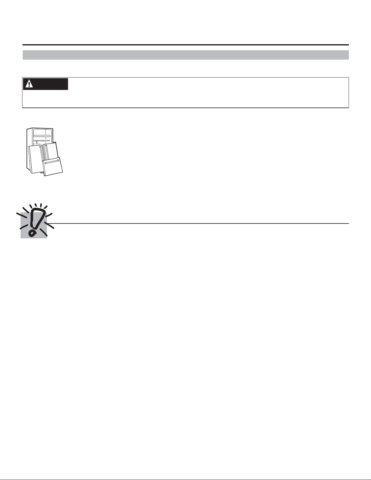
PROPER DISPOSAL OF YOUR OLD REFRIGERATOR
WARNING
Remove fresh-food and freezer doors from the refrigerator, prior to disposal. Failure to do so can result
in child entrapment which can lead to death or brain damage.
IMPORTANT:
Suffocation and child entrapment hazard.
Child entrapment and suffocation are not problems
of the past. Junked or abandoned refrigerators are
still dangerous even if they will sit for “just a few
days.” If you are getting rid of your old refrigerator,
please follow the instructions below to help prevent
accidents.
Before You Throw Away Your Old Refrigerator
or Freezer:
Take off the fresh food and freezer doors.
Leave the shelves in place so that children may not
easily climb inside.
Refrigerants
All refrigeration products contain refrigerants,
which under federal law must be removed prior
to product disposal. If you are getting rid of an old
refrigeration product, check with the company
handling the disposal about what to do.
READ AND FOLLOW THIS SAFETY INFORMATION CAREFULLY.
SAVE THESE INSTRUCTIONS
4
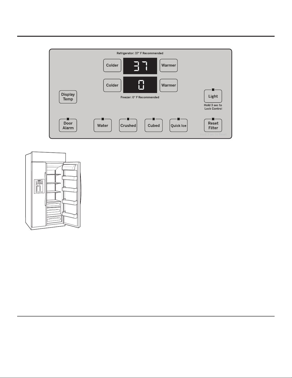
About the temperature controls. GEAppliances.com
The temperature controls are preset in the factory at 37°F for
the refrigerator compartment and 0°F for the freezer compartment.
Allow 24 hours for the temperature to stabilize to the preset
recommended settings.
The temperature controls can display both the SET temperature
as well as the actual temperature in the refrigerator and freezer.
The actual temperature may vary slightly from the SET temperature
based on usage and operating environment.
NOTE: The refrigerator is shipped with protective film covering
the temperature controls. If this film was not removed during
installation, remove it now.
To change the temperature, press and release
the WARMER or COLDER button. SET will illuminate in the
display, as well as the set temperature. To change the
temperature, tap either the WARMER or COLDER button
(while SET is illuminated) until the desired temperature
is displayed. Refrigerator temperatures can be adjusted
between 34°F and 47°F and
the freezer temperatures can be adjusted
between –6°F and +8°F.
Performance Air Flow System
Once the desired temperature has been set,
the temperature display will clear after 10 seconds.
To display the temperature, the DISPLAY TEMP button
may be tapped.
Several adjustments may be required. Each time you
adjust controls, allow 24 hours for the refrigerator to
reach the temperature you have set.
The Performance Air-Flow System is designed to
maximize temperature control in the refrigerator
and freezer compartments. This unique special feature
consists of the Air Tower along the back
wall of the refrigerator and the freezer. Placing food
in front of the louvers on these components will not
affect performance.
5
About ClimateKeeper® with dual evaporators.
How it Works
The ClimateKeeper with dual evaporators system
IHDWXUHVWZRHYDSRUDWRUV³RQHIRU
the refrigerator and one for the freezer.
This provides two separate cooling systems, and
separates the airflow between the fresh food and
freezer compartments during normal cooling
operations.
The separate airflow system minimizes
the mixing of air between the two compartments,
which reduces fresh food odor transfer to improve
the taste of ice.
The ClimateKeeper system also reduces
the number of defrosting cycles in the freezer
evaporator, thereby reducing freezer burn.
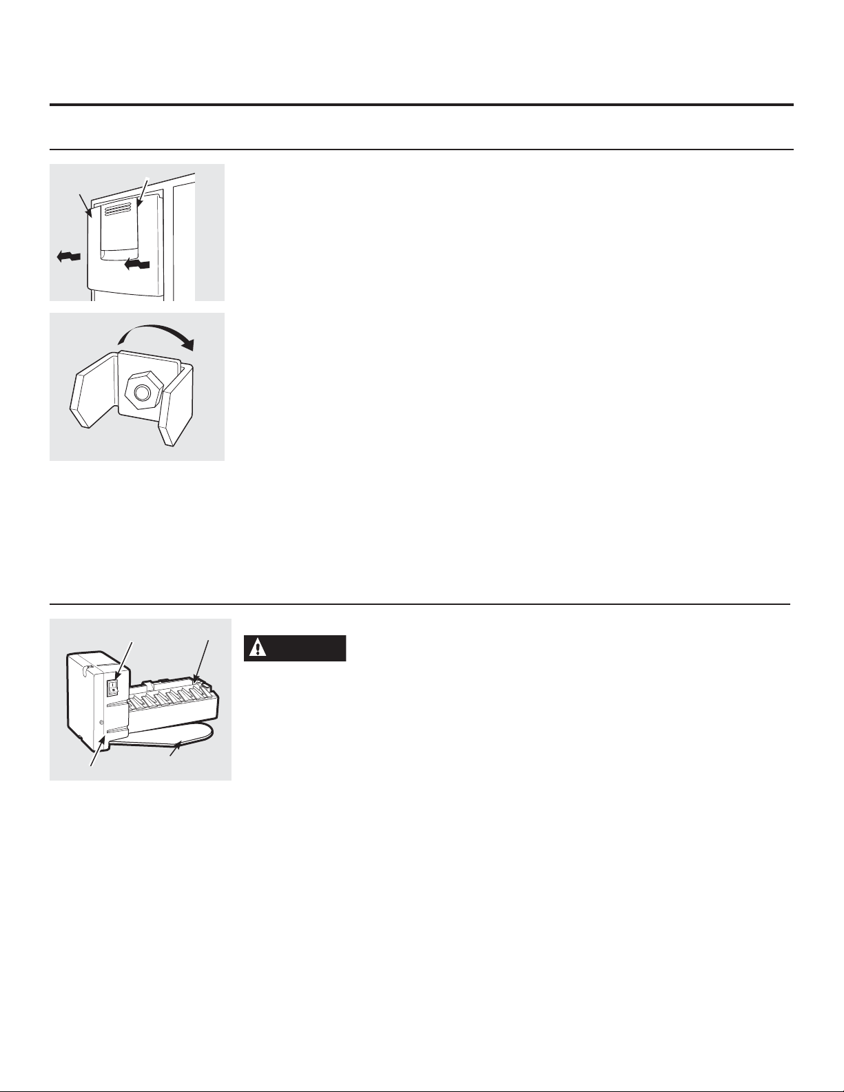
About the water filter.
Water filter cartridge
The water filter cartridge is located in the back upper right corner of
the refrigerator compartment.
When to replace the filter on models
with a replacement indicator light
There is a replacement indicator light for the water filter cartridge
on the dispenser. This light will turn orange to
tell you that you need to replace the filter soon.
The filter cartridge should be replaced when the replacement
indicator light turns red or if the flow of water to the dispenser or
icemaker decreases.
When to replace the filter on models
without a replacement indicator light
The filter cartridge should be replaced every six months
or earlier if the flow of water to the dispenser or
icemaker decreases.
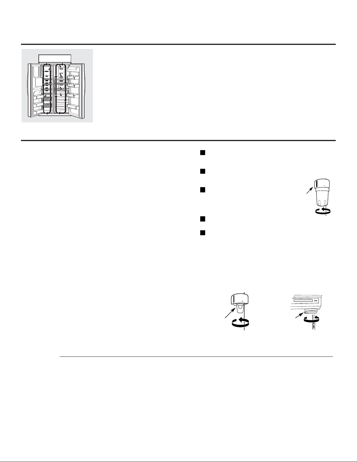
Removing the filter cartridge
If you are replacing the cartridge, first remove the old one
by slowly turning it to the left. Do not pull down on the cartridge. A
small amount of water may drip down.
CAUTION: To reduce the risk associated with property damage due
to water leakage, read and follow instructions before installation
and use of this system. Installation and use MUST comply with all
state and local plumbing codes.
Installing the filter cartridge
Fill the replacement cartridge with water from the tap
1
to allow for better flow from the dispenser immediately
after installation.
Line up the arrow on the cartridge and the cartridge holder. Place
2
the top of the new cartridge up inside the holder.
Do not push it up into the holder.
Slowly turn it to the right until the filter
3
cartridge stops. DO NOT OVERTIGHTEN.
As you turn the cartridge, it will
automatically raise itself into position.
The cartridge will move about a ½ turn.
Run water from the dispenser for 1-1/2 gallons (about three
4
minutes) to clear the system and prevent sputtering.
Press and hold the RESET WATER FILTER pad (on some models) on
5
the dispenser for three seconds.
NOTE: A newly installed water filter cartridge may cause water
to spurt from the dispenser.
Cartridge
Holder
Filter bypass plug
ou must use the filter bypass plug when a replacement filter
Y
cartridge is not available. The dispenser and the icemaker will not
operate without the filter or filter bypass plug.
Filter Bypass
Plug
Filter Bypass
Plug
SmartWater
To use the filter bypass plug on Water by Culligan
you must first remove the filter adaptor from the cartridge holder by
turning it to the left.
Water by Culligan
™
models,
)RUWKHPD[LPXPEHQH¿WWR\RXU¿OWUDWLRQV\VWHP*(UHFRPPHQGVWKHXVHRI*(EUDQGHG¿OWHUVRQO\8VLQJ*(EUDQGHG¿OWHUVLQ*(
and Hotpoint
®
UHIULJHUDWRUVSURYLGHVRSWLPDOSHUIRUPDQFHDQGUHOLDELOLW\*(¿OWHUVPHHWULJRURXVLQGXVWU\16)VWDQGDUGVIRUVDIHW\
DQGTXDOLW\WKDWDUHLPSRUWDQWIRUSURGXFWVWKDWDUH¿OWHULQJ\RXUZDWHU*(KDVQRWTXDOL¿HGQRQ*(EUDQGHG¿OWHUVIRUXVHLQ*(
DQG+RWSRLQWUHIULJHUDWRUVDQGWKHUHLVQRDVVXUDQFHWKDWQRQ*(EUDQGHG¿OWHUVPHHW*(·VVWDQGDUGVIRUTXDOLW\SHUIRUPDQFHDQG
reliability.
,I\RXKDYHTXHVWLRQVRUWRRUGHUDGGLWLRQDO¿OWHUFDUWULGJHVYLVLWRXUZHEVLWHDWZZZJHZDWHU¿OWHUVFRPRUFDOO*(3DUWVDQG
Accessories, 800.626.2002.
Customers in Canada should consult the yellow pages for the nearest Camco Service Center.
6
About the shelves and bins. GEAppliances.com
Not all features are on all models.
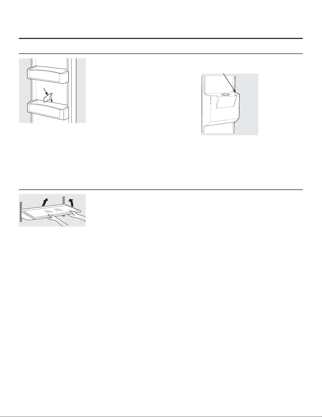
Refrigerator Door Bins and Freezer Door Bins
Do not block
NOTE: Make sure
that items do not
block or fall into the
ice chute.
Snugger
All door bins, except for the deep gallon
door bin and freezer bins, are adjustable
and can be moved up and down to meet your
storage needs. The deep gallon door
bin and the freezer bins can be removed
for cleaning.
To remove any bin: Lift the bin up and pull
it toward you.
Refrigerator bins
To replace or relocate: Engage the back side
of the bin in the molded supports on the door.
Then push down on the front of the bin.
Bin will lock in place.
The snugger helps prevent tipping, spilling
or sliding of small items stored on the door shelf.
Place a finger on either side of the snugger near
the rear and move it back
and forth to fit your needs.
Spillproof Shelves and Freezer Shelves
The special edges are designed to help prevent
spills from dripping to lower shelves.
To remove shelves:
Tilt shelf up at front, then lift it up and out of
tracks on rear wall of refrigerator.
To replace shelves:
Select desired shelf height. With shelf front
raised slightly, engage top lugs in tracks at rear
of cabinet. Then lower front of shelf until it locks
into position.
Make sure you push the shelves all the way
back in before you close the door.
Top freezer bin
7
About the refrigerator doors.
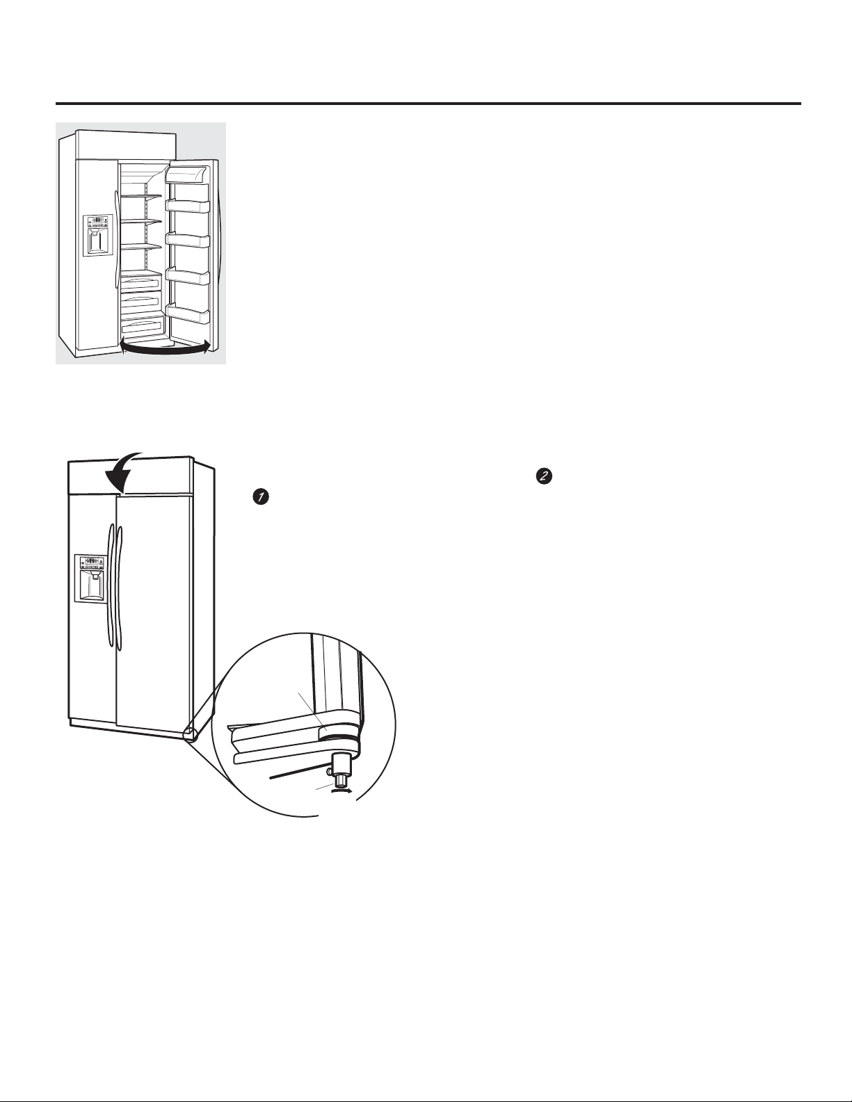
Refrigerator Doors
When the door is at 90° open,
it will automatically close.
Beyond this stop the door will stay open.
The refrigerator doors may feel different than
the ones you are used to. The secure door
opening/closing feature makes sure the doors
close all the way and are securely sealed.
When opening and closing the door,
you will notice a stop position. When
the door is at the 90° stop position,
it will automatically close.
Door Alignment
If doors are uneven, adjust the refrigerator door.
Using a 7/32” socket wrench, turn the door
adjusting screw clockwise to raise the
door, counterclockwise to lower
the door. (A nylon plug, imbedded in the
threads of the pin, prevents the pin from
turning unless a wrench is used.)
The resistance you feel at the stop
position will be reduced as the door
is loaded with food.
After one or two turns of the wrench, open
and close the refrigerator door
and check the alignment at the top
of the doors.
Bushing
Door Hinge
Case Hinge
7/32" Wrench
Raise
Clockwise
8
About the drawers and baskets. GEAppliances.com
Not all features are on all models.
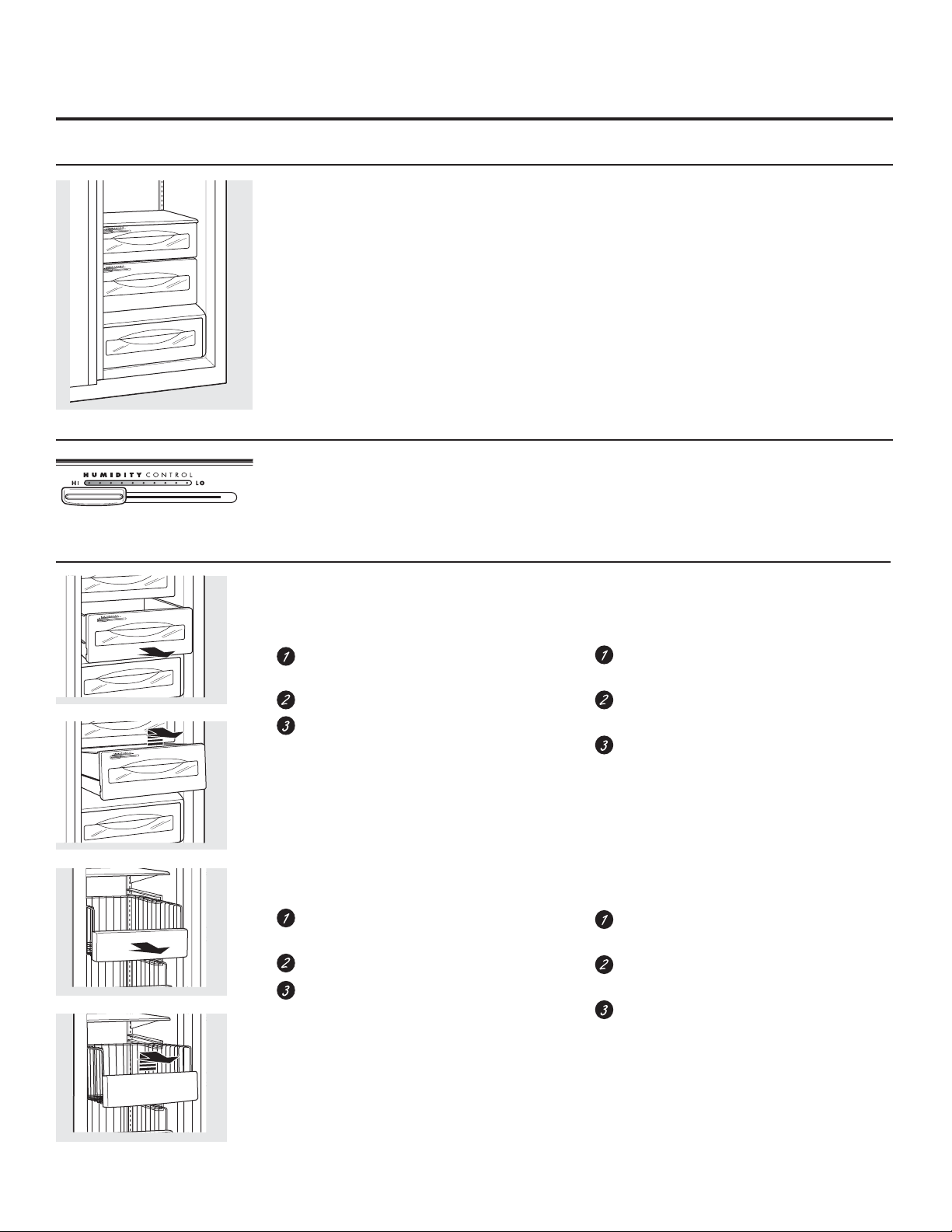
Fruit and Vegetable Drawers
Excess water that may accumulate in the
bottom of the drawers should be wiped dry.
Adjustable Humidity Drawers
Slide the control all the way to the HI setting to
provide high humidity recommended for most
vegetables.
Slide the control all the way to the LO
setting to provide lower humidity levels
recommended for most fruits.
How to Remove and Replace the Drawers and Freezer Baskets
To remove fresh food drawers:
Pull the desired drawer out to the
stop position.
Lift up slightly on the front of the drawer.
Pull the drawer slightly forward and
out of the refrigerator.
To remove freezer baskets:
Pull the desired basket out to the
stop position.
Lift up slightly on the front of the basket.
Pull the basket slightly forward and
out of the freezer.
To replace fresh food drawers:
Tip the back rollers of the drawer behind the
rollers in the track.
Lower the front of the drawer into normal
position.
Slide the drawer to the back of the
refrigerator.
To replace freezer baskets:
Place the back corners in the rail
with the basket tilted up.
Lower the basket down to the normal
position.
Slide the basket to the back of the freezer.
9
About the ice and water dispenser and automatic icemaker.
A newly installed refrigerator may take 12 to 24 hours to begin making ice.
Ice Storage
Bin
Access Door
Rotate
Drive
Mechanism
Ice Storage Bin
To remove:
Lift up the access door to reach the
icemaker. Set the icemaker power switch
to the O (off) position. With the access door
closed, support the storage bin at
the bottom while slightly lifting. Pull bin
straight out.
To replace:
Slide the bin back until the tab on
the bin locks into the slot on the shelf.
If the bin does not go all the way back,
remove it and rotate the drive mechanism 1/4
turn. Then push the bin back again.
Important facts about your
ice and water dispenser
Do not add ice from trays or bags to the
storage bin. It may not crush or dispense well.
Avoid overfilling glass with ice and use of
narrow or extra-tall glasses. Backed-up ice
can jam the chute or cause the door in the
chute to freeze shut. If ice is blocking the
chute, poke it through with a wooden spoon.
Beverages and foods should not be
quick-chilled in the ice storage bin.
Cans, bottles or food packages in the storage
bin may cause the icemaker
or auger to jam.
To keep dispensed ice from missing
the glass, put the glass close to, but not
touching, the dispenser opening.
Some crushed ice may be dispensed
even though you selected CUBED. This
happens occasionally when a few cubes
accidentally get directed to the crusher.
After crushed ice is dispensed, some water
may drip from the chute.
The first glass of water dispensed may
be warmer than the following ones.
This is normal.
Green Power
Light
Power
Switch
Feeler Arm
Ice maker
Automatic Icemaker
CAUTION
moving parts of the ejector mechanism, or with
the heating element (located on the bottom of
the ice maker) that releases the cubes. Do not
place fingers or hands on the automatic ice
making mechanism while the refrigerator is
plugged in.
A newly-installed refrigerator may take 12–24
hours to begin making ice.
The icemaker will produce seven cubes per
F\FOH³DSSUR[LPDWHO\F\FOHVRUPRUHLQ
a 24-hour period, depending on freezer
compartment temperature, room temperature,
number of door openings
and other use conditions.
If the refrigerator is operated before the water
connection is made to the icemaker, set the
power switch to O (off).
When the refrigerator has been connected to
the water supply, set the power switch to I (on).
The green light will come on.
Avoid contact with the
Throw away the first full bucket of ice.
Be sure nothing interferes with the sweep of the
feeler arm.
When the bin fills to the level of the feeler arm,
the icemaker will stop producing ice.
It is normal for several cubes to be joined
together.
If ice is not used frequently, old ice cubes will
become cloudy, taste stale and shrink.
After the icemaker has been turned on again,
there will be a delay of about 45 minutes before
the icemaker resumes operations.
NOTE: In homes with lower-than-average water
pressure, you may hear the icemaker water
valve cycle on several times when making one
batch of ice. Recommended water pressure is
60 psi.
10
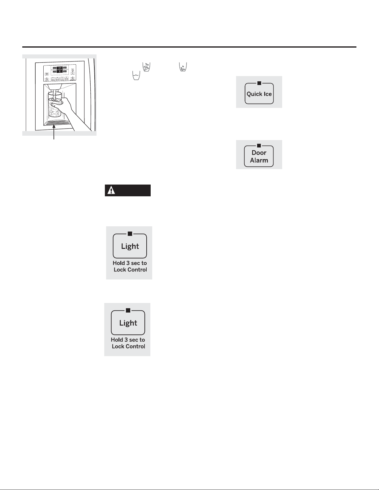
About the ice and water dispenser. GEAppliances.com
To Use the Dispenser
Spill Shelf
Select CUBED , CRUSHED
or WATER .
Press the glass gently against the middle of the
dispenser pad.
The spill shelf is not self-draining. To reduce
water spotting, the shelf and its grille should be
cleaned regularly.
If no water is dispensed when the
refrigerator is first installed, there may
be air in the water line system. Press the
dispenser arm for at least two minutes to
remove trapped air from the water line
and to fill the water system. To flush out
impurities in the water line, throw away the
first six glassfuls of water.
CAUTION
other objects into the ice crusher discharge
opening.
Never put fingers or any
Locking the Dispenser
Press the LIGHT button
for 3 seconds to lock the
dispenser and control
panel. To unlock, press and
hold the button again for 3
seconds.
Quick Ice
Door Alarm
When you need ice in a
hurry, press this button to
speed up ice production.
This will increase ice
production for the following
48 hours or until you
press the button again.
To turn the Door
Alarm on, press the
DOOR ALARM button
once. The ACTIVE light will
come on. To turn it off,
press it again. When the
DOOR ALARM is active, the
ACTIVE light will flash if you
open the door and beep
if you keep the door open
for more than 2 minutes.
The light goes out and the
beeping stops when you
close the door.
Dispenser Light
This button turns the light on
the dispenser on and off. The
light also comes on when the
dispenser pad is pressed. If
this light burns out, it should
be replaced with a 6 watt
12V maximum bulb.
11

Care and cleaning of the refrigerator.
Cleaning the Outside
Dispenser drip area.
The spill shelf and the area beneath it should
be cleaned periodically with a mild liquid dish
detergent.
Dispenser pad. Before cleaning, lock the
dispenser by pressing the LOCK/LIGHT
button for 3 seconds to prevent activating the
dispenser. Clean with warm water and a mild
liquid dish detergent. Rinse thoroughly and wipe
dry. Unlock the dispenser by pressing the LOCK/
LIGHT button for 3 seconds.
Door handles. Clean with a cloth dampened
with soapy water. Dry with a soft cloth.
Do not wipe the refrigerator with a soiled dish
cloth or wet towel. These may leave a residue
that can damage the finish. Do not use scouring
pads, powdered cleaners, bleach or cleaners
containing bleach because these products can
scratch and damage the finish.
Cleaning the Inside
Turn off power at the circuit breaker or fuse
box before cleaning. If this is not practical,
wring excess moisture out of sponge or cloth
when cleaning around switches, lights or
controls.
8VHZDUPZDWHUDQGEDNLQJVRGDVROXWLRQ³
about a tablespoon (15 ml) of baking soda
to a quart (1 liter) of water. This both cleans and
neutralizes odors. Thoroughly rinse and wipe
dry.
The stainless steel doors and door handles
(on some models) can be cleaned with a
commercially available stainless steel cleaner.
Cleaners with oxalic acid such as Bar Keepers
Friend Soft Cleanser™ will remove rust, tarnish
and small blemishes. Use only a liquid cleanser
free of grit and rub in the direction of the brush
lines with a damp soft sponge. Do not use
appliance wax or polish on the stainless steel.
Other parts of the refrigerator, including door
gaskets, snack pan and vegetable drawers, ice
storage bin and all plastic parts, can be cleaned
the same way.
Do not wash the tray or any plastic refrigerator
parts in the dishwasher.
CAUTION
or covers with warm water when they are
cold. Glass shelves and covers may break
if exposed to sudden temperature changes
or impact, such as bumping or dropping.
Tempered glass is designed to shatter into
many small pieces if it breaks.
Do not clean glass shelves
12

GEAppliances.com
Preparing for Vacation
For long vacations or absences, remove
food and unplug the refrigerator. Clean
the interior with a baking soda solution of one
tablespoon (15 ml) of baking soda to one quart
(1 liter) of water. Leave the doors open.
Set the icemaker power switch to the O (off)
position and shut off the water supply to
the refrigerator.
Preparing to Move
Secure all loose items such as shelves and
drawers by taping them securely in place
to prevent damage.
WARNING
of this refrigerator, and to reduce the risk of
personal injury or damage to the product,
A MINIMUM OF 4 PEOPLE ARE REQUIRED
TO BRING THE UNIT INTO THE HOME AND
2 PEOPLE ARE REQUIRED FOR PROPER
INSTALLATION.
Be sure the refrigerator stays in an upright
position during moving.
Due to the weight and size
If the temperature can drop below freezing,
have a qualified servicer drain the water supply
system to prevent serious property damage
due to flooding.
13
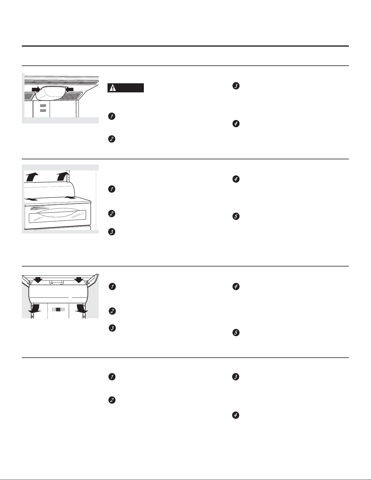
Replacing the light bulbs.
Setting the controls to OFF does not remove power to the light circuit.
5HIULJHUDWRU&RPSDUWPHQW³8SSHU/LJKW
(appearance may vary)
CAUTION
Burned out bulbs may break when being
replaced.
Raise the grille panel, set the master power
switch to the O (off) position and allow
lamps to cool.
To remove the light shield, press on the
sides of the shield and pull down.
5HIULJHUDWRU&RPSDUWPHQW³/RZHU/LJKW
This light is located above the top drawer.
Raise the grille panel, set the master power
switch to the O (off) position
and allow lamps to cool.
Remove items from the shelf above
the light shield. Remove the shelf.
Use both hands to grasp each end
of the light shield. Press in on the bottom of
the shield with your thumbs while rotating
the cover up and out.
Light bulbs may be hot.
Replace the bulbs with appliance bulbs of
the same or lower wattage. Replace the
shield by engaging the bottom tab into the
slot and applying light forward pressure
until the shield snaps in place.
Set the master power switch to the I (on)
position and close the grille panel.
Replace the bulb with an appliance bulb of
the same or lower wattage. Replace the
shield by engaging the bottom tab into the
slot and applying light forward pressure
until the shield snaps in place.
Set the master power switch to the I (on)
position and close the grille panel.
Freezer Compartment
Raise the grille panel, set the master power
switch to the O (off) position and allow
lamps to cool.
Remove the items from the shelf just below
the light shield. Remove the shelf.
To remove the light shield, press down on
the top of the shield and pull the tabs out of
the slots. Tilt the shield forward and out.
Dispenser
Raise the grille panel, set the master power
switch to the O (off) position
and allow lamps to cool.
The bulb is located in the dispenser under
the control panel. Remove
the two screws from the light shield.
Slide the light shield toward the dispenser
to disengage the tabs, then remove the
light shield. Remove the light bulb by
turning it counterclockwise.
Replace the bulb with an appliance
bulb of the same or lower wattage,
and reinstall the light shield. Replace
the shield by engaging the bottom tab into
the slot and applying light forward pressure
until the shield snaps in place.
Set the master power switch to the I (on)
position and close the grille panel.
Replace the bulb with a bulb
of the same size and wattage. Replace
the light shield by sliding the tabs into
the slots in the front of the dispenser.
Replace the two screws.
Set the master power switch to the I (on)
position and close the grille panel.
14
Installation
Built-In Side-By-Side
Refrigerators
Instructions
If you have questions, call 800.GE.CARES (800.432.2737) or visit our website at: GEAppliances.com
In Canada, call 1.800.561.3344 or visit our website at: www.geappliances.ca
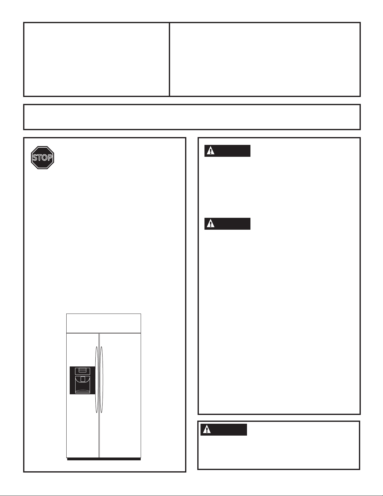
BEFORE YOU BEGIN
STOP
•
IMPORTANT ³ Observe all governing
codes and ordinances.
•
Note to Installer – Be sure to leave these
LQVWUXFWLRQVIRUWKHFRQVXPHU·VDQGORFDO
LQVSHFWRU·VXVH
•
Note to Consumer – Keep these instructions
ZLWK\RXU2ZQHU·V0DQXDOIRUIXWXUHUHIHUHQFH
•
Skill Level – Installation of this refrigerator
requires basic mechanical, carpentry and
plumbing skills. Proper installation is the
responsibility of the installer. Product failure
due to improper installation is not covered
under the GE Appliance Warranty.
See warranty information.
•
Completion Time – 90 minutes (new installations
require more time than replacement installations).
Read these instructions completely
and carefully.
PSB42YS, PSB42YG, PSB48YS, PSB48YG
WARNING
Due to the weight and size of this refrigerator,
and to reduce the risk of personal injury or
damage to the product, A MINIMUM OF 4 PEOPLE
ARE REQUIRED TO BRING THE UNIT INTO THE
HOME AND 2 PEOPLE ARE REQUIRED FOR PROPER
INSTALLATION.
WARNING
• These refrigerators are top-heavy and must
be secured to prevent the possibility of tipping
forward. Anti-Tip protection is required.
See Step 4 on page 34 for details.
• Use this appliance only for its intended purpose.
• Immediately repair or replace electric power
supply cords that become frayed or damaged.
• Set the Master Power switch to the O (OFF)
position before cleaning or making repairs.
• Repairs should be made by a qualified service
technician.
For GE Profile
call 1.800.432.2737.
For GE Profile service in Canada,
call 1.800.561.3344.
For GE Profile Parts and Accessories,
call 1.800.626.2002.
GEAppliances.com (in Canada, geappliances.ca)
™
local service in your area,
READ CAREFULLY.
KEEP THESE INSTRUCTIONS.
WARNING
To reduce the risk associated with choking, do
not allow children under 3 years of age to have
access to small parts during the installation of this
product.
15
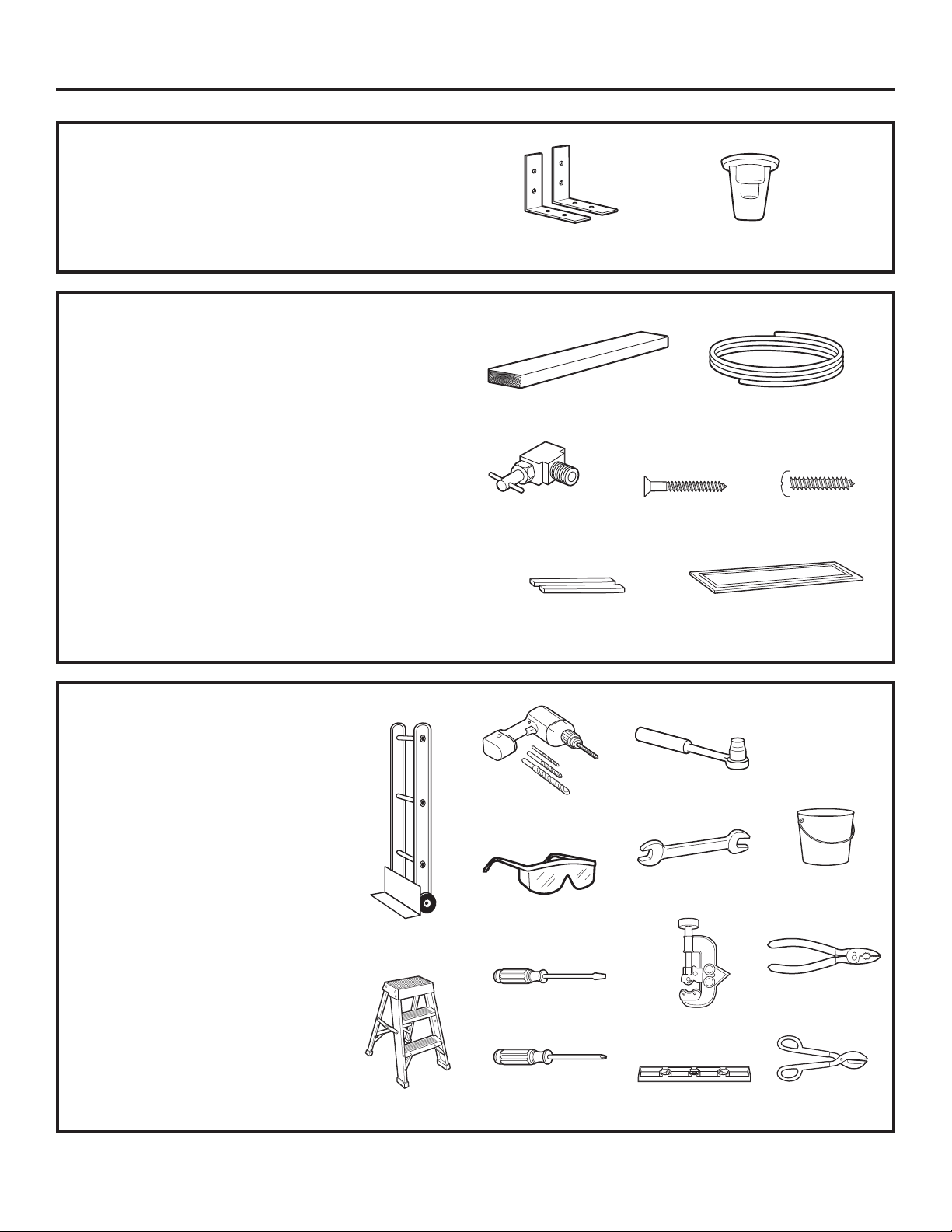
Installation Instructions
HARDWARE SUPPLIED
• Water filter bypass plug
• Anti-Tip brackets
MATERIALS REQUIRED
• 36” long, 2” x 4” wood block for Anti-Tip bracket
installation
• #12 or #14 wood screws for Anti-Tip bracket
• Screws to secure refrigerator to cabinets
• 1/4” O.D. copper water line tubing or GE
SmartConnect
• Water shutoff valve
• Custom panels for doors and grille panel
(if installing custom panels)
• Special 3M Dual Lock adhesive strips for
1/4” side panels (if installing side panels)
™
refrigerator tubing kits
Anti-Tip Brackets Water Filter Bypass Plug
36” Wood Block 1/4” O.D. Copper Water Line
Water Shutoff
Valve
#12 or #14
Wood Screws
Tubing or GE SmartConnect™
Refrigerator Tubing Kit
Screws
TOOLS REQUIRED
• Tinsnips to cut banding
• Stepladder
• Bucket
• Level
• Appliance dolly
• Tubing cutter
• Flathead screwdriver
• 1/2” open-end wrench
• #2 Phillips screwdriver
• Drill and appropriate bits
• 7/32”, 1/2” sockets
• Safety glasses
• 7/16” open-end wrench
• Pliers
Appliance Dolly
Special 3M Dual Lock
Adhesive Strips
Drill & Bits
Safety Glasses
Flathead
Screwdriver
Sockets
Open-end
Wrenches
Tubing Cutter
Custom Panels
Bucket
Pliers
Stepladder
16
Phillips Head
Screwdriver
Level
Tinsnips
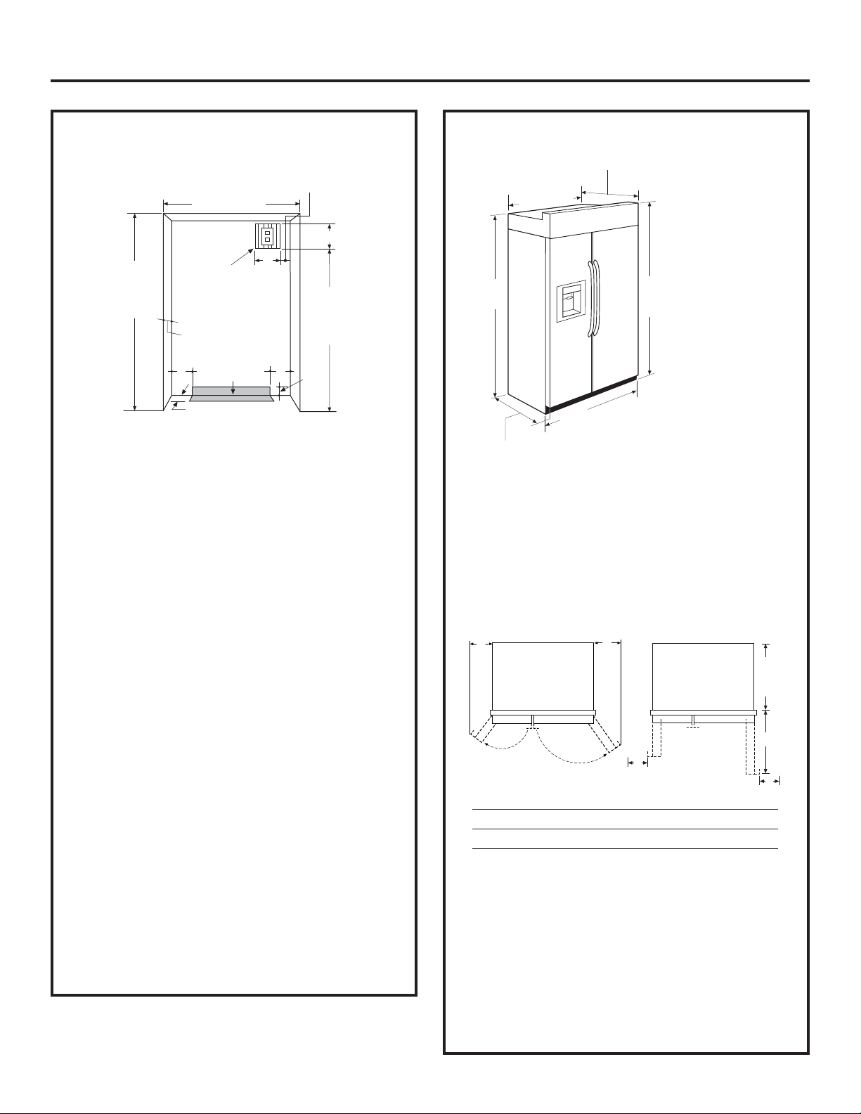
THE INSTALLATION SPACE
Installation Instructions
DIMENSIONS AND CLEARANCES
3"
*Finished Width
7"
84 1/2" max
83 1/2" min
Finished
Opening
Electrical
Area
24"
5"
Water Supply
3 1/2"
7"
74"
From Floor
to Bottom
of Electrical
5"
3 1/2"
*The finished cutout width must be: 41-1/2”
for 42” models and 47-1/2” for 48” models
Water and Electrical Locations
The opening must be prepared with the electrical
and water supply located as shown.
The cutout depth must be 24”
The refrigerator will project forward, slightly
beyond adjacent cabinets, depending on your
installation.
Additional Specifications
• A 120 volt, 60Hz, 15 or 20 amp power supply
is required. An individual properly grounded
branch circuit or circuit breaker is
recommended. Install a properly grounded
3-prong electrical receptacle recessed into
the back wall. Electrical must be located on
rear wall as shown.
Note: GFI (ground fault interrupter) is not
recommended.
• Water line can enter the opening through the
floor or rear wall. The water line installed should
be 1/4” O.D. copper tubing or GE SmartConnect
tubing between the cold water line and water
connection location. The line should be long
enough to extend to the front of the refrigerator.
Installation of an easily accessible shutoff valve
in the water line is required.
*81-3/4"
at Rear
Depth Including
Handles 26-7/8"
25-3/8" Case Depth
**Case Width
*84" From
Floor to
Top Frame
42" Frame-to-Frame for 42" Models
48" Frame-to-Frame for 48" Models
*Shipping height
The front height
may be adjusted
from 83-1/2” to
84-1/2” by adjusting
front and rear
leveling legs a
maximum of 1”.
**The case width must be: 41” for 42”
models and 47” for 48” models
Product Clearances
These refrigerators are equipped with a 2 position
door stop. The factory set 130° door swing can be
adjusted to 90° if clearance to adjacent cabinets
or walls is restricted.
130° Door Swing 90° Door Swing
A
B
23-7/8“
Behind
Frame
C
D
D
Models A B C D
42” 12-3/16” 16” 24” 5”
48” 13-7/16” 18-9/16” 28” 5”
Allow minimum clearances for Freezer door
™
(Dimension A) and Fresh Food door (Dimension B)
for a full 130° door swing and to allow for drawer
removal.
Four inch (4”) minimum clearance is required when
door swing is adjusted to 90°. If the 90° door stop
position is used, drawer access is maintained, but
drawer removal is restricted.
See illustrations, pages 18 and 19, to determine
door swing interaction with adjacent cabinets or
countertops.
17
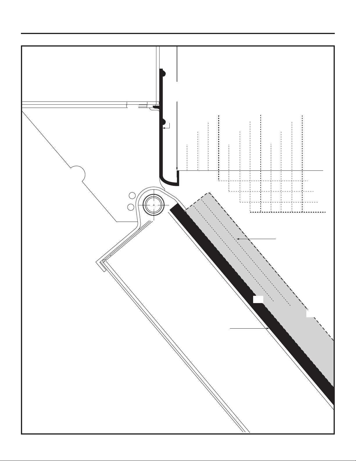
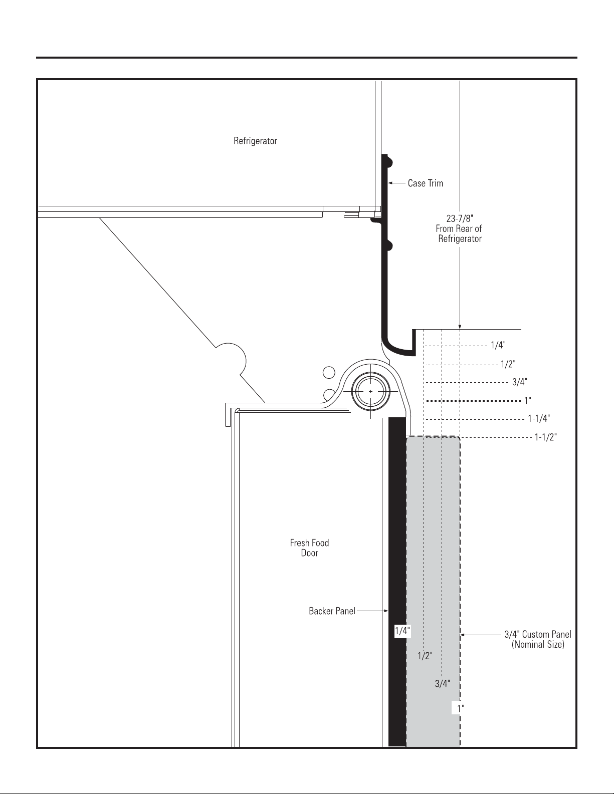
Installation Instructions
Refrigerator
23-7/8" From
Rear of
Refrigerator
Case
Trim
1/4"
1/2"
3/4"
1"
1-1/4"
1-1/2"
1-3/4"
2"
3"
2-3/4"
2-1/2"
2-1/4"
1/4"
1/2"
3/4"
1"
3/4" Custom Panel
(Nominal Size)
Top View
130° Door Swing
(factory setting)
Scale 1:1
Fresh Food
Door
18
Backer Panel
1/4"
1/2"
3/4"
1"
Installation Instructions
Top View
90° Door Swing
(optional setting)
Scale 1:1
19
Installation Instructions
CUSTOMIZATION BASICS:
Stainless Steel Wrapped Models
42”ZLGHPRGHO³36%<6
48”ZLGHPRGHO³36%<6
Stainless Steel wrapped refrigerators have wrapped
doors and grille panels, and beveled edges. These
models are shipped ready for installation.
Trimmed Models
42”ZLGHPRGHOV³36%<*
48”ZLGHPRGHOV³36%<*
Trimmed refrigerators are designed to be
customized with decorative panels. Field installed
custom door and grille panels are required. Panels
can be framed or full-width and can use either the
pre-installed handles or custom handles provided
by your cabinet manufacturer.
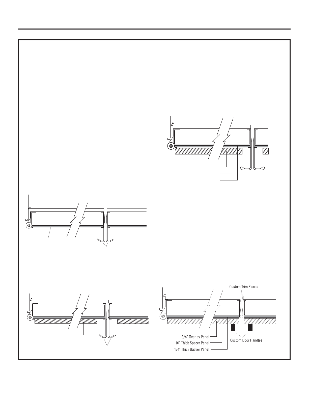
Framed Custom Panels
<RXPD\LQVWDOOFXVWRPSDQHOVIURP\RXUFDELQHW
manufacturer. The decorative panel slides into
the factory installed trim. A 1/4” finished panel
can be used.
Framed Panel
Door Handles
<RXPD\LQVWDOOD” panel attached to a 1/4”
backer panel. If the pre-installed door handles are
used, the backer panel will be exposed by the handle
and therefore must be finished (page 24). Custom
handles can also be used.
Full-Width Overlay Custom Panels
Full-width overlay custom panels are designed
to slide into the factory-installed trim, no kits
required. In this design, you can achieve a nearly
trimless appearance.
A 0.10” spacer panel must be installed between
the finished 1/4” backer panel and 3/4”
appearance panel. If the pre-installed door
handles are used, the backer panel will be
exposed near the handle and therefore
must be finished (page 24).
3/4" Overlay Panel
.10" Thick Spacer Panel
1/4" Thick Backer Panel
Door Handles
The pre-installed handles can accommodate
both framed or overlay panels. Custom handles of
your choice, supplied by your cabinet maker, can
be installed only on 3/4” overlay panels. When
installing custom handles, measure to ensure
the mounting for the handles selected will clear
the dispenser when installed on the freezer door.
Handles need to mount on the upper and lower
wood panels of the freezer door and not
on the dispenser. If a custom handle is used, only
the 3/4” overlay panel must be exposed, and the
custom trim pieces should be installed (page 38).
3/4" Custom Panel
Door Handles
20
Installation Instructions
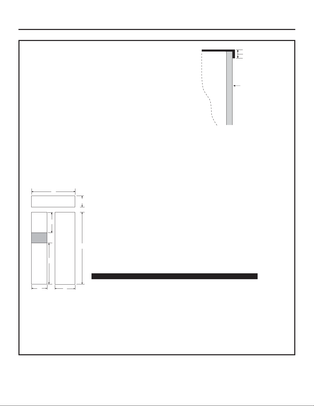
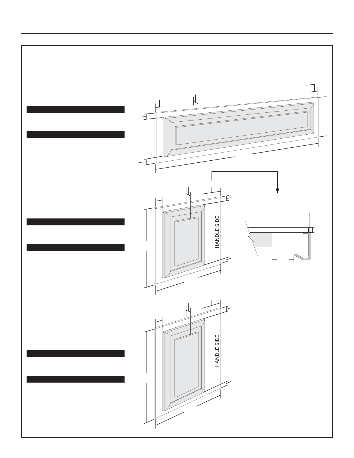
1/4” FRAMED PANEL DIMENSIONS
If you choose to install framed panels, they must be
cut to the dimensions shown. The panels will slide
into the frame on the doors and grille.
A
Grille Panel
B
5/16"
Door
Trim
Reveal
1/4"
Panel
IMPORTANT NOTE: Maximum weight
is 70 pounds for the Fresh Food panel,
45 pounds total for Freezer panels and
15 pounds for the grille panel.
Dispenser
Cutout
Freezer
Panel
G
C
F
Panel
D
Front Panel Dimensions (in inches)
A B C D E F G
42” Models 40-1/8 10-7/8 68 22-1/2 16-1/2 35-1/4 18
48” Models 46-1/8 10-7/8 68 26-1/2 18-1/2 35-1/4 18
Fresh Food
E
IMPORTANT NOTE: Dispenser Trim
The refrigerator is supplied with factory installed dispenser trim.
• If panel is less than 1/4” thick, a noticeable gap will be created
around the dispenser trim. Foam tape may be applied on
the door to improve the fit.
• If panel is more than 1/4” thick, the panel will not fit behind
the trim.
21
Installation Instructions
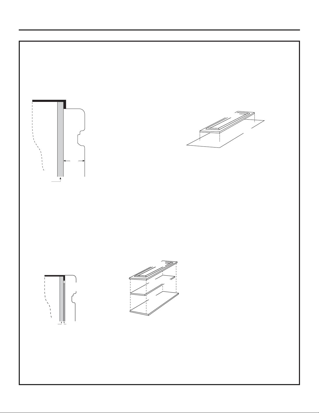
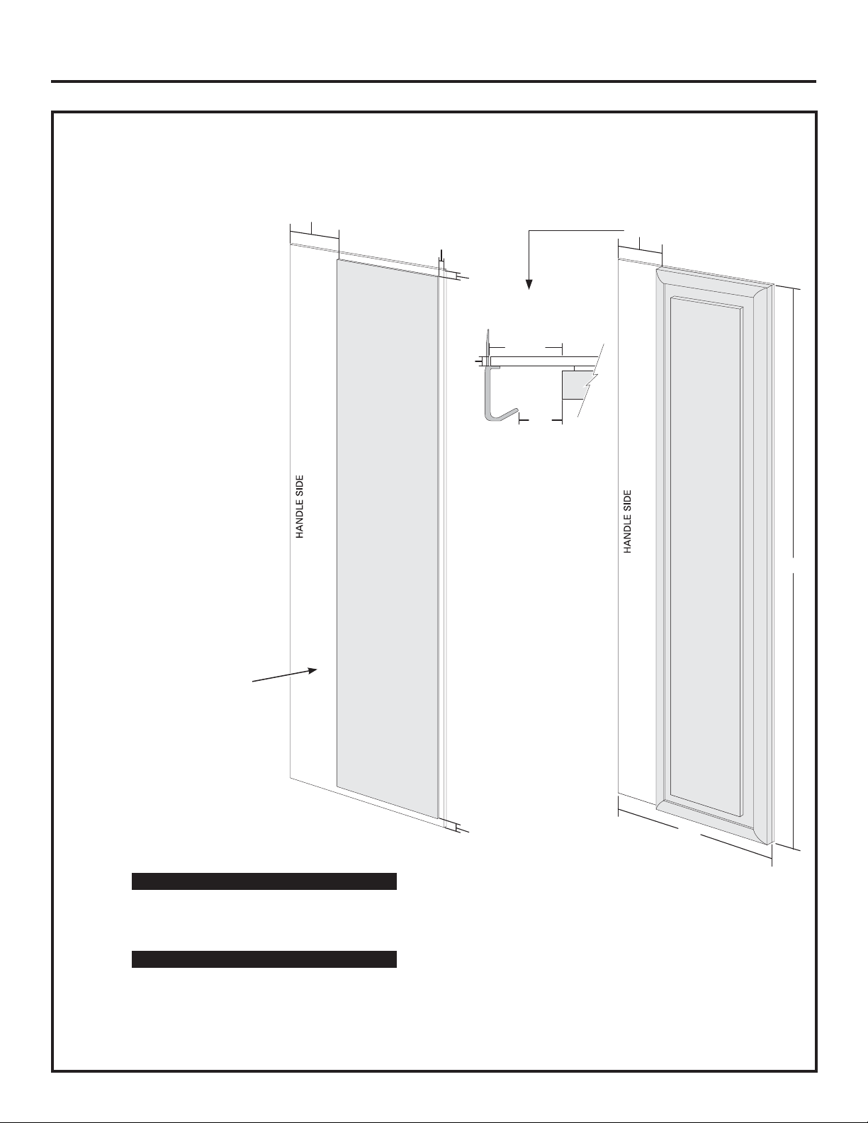
3/4” FRAMED CUSTOM PANEL OPTION
For a more custom appearance, 3/4” framed custom panels
may be installed on trimmed models. The overlay panel is
secured to a 1/4” finished backer panel. The assembled
custom panel then slides into the trim with the same procedure
described on page 37.
Door
3/4"
Custom
Overlay
Panel
3/4"
NOTE: Left-to-right offset is not
equal to top-to-bottom offset.
1/4"
Backer
Panel
.250 + .750 = 1.000 Maximum Total Panel
Thickness
3/4” FULL-WIDTH OVERLAY
CUSTOM PANEL OPTION
This design provides a nearly trimless appearance. The full width overlay
panel covers most of the door trim. In this design, a spacer panel must
be installed between the finished backer and overlay panel.
Overlay Panel
Overlay Panel
Backer Panel
Custom
Overlay
Door
1/4"
Backer
Panel
.250 + .10 + .750 = 1.100 Maximum Total Panel Thickness
Panel
.10 Inch
Spacer
NOTE: Left-to-right offset is not equal
to top-to-bottom offset.
IMPORTANT NOTE: Maximum total weight
is 70 pounds for any assembled Fresh Food
panel, 45 pounds total for the Freezer panels
and 15 pounds for the grille panel.
Spacer Panel
Backer Panel
22
Installation Instructions
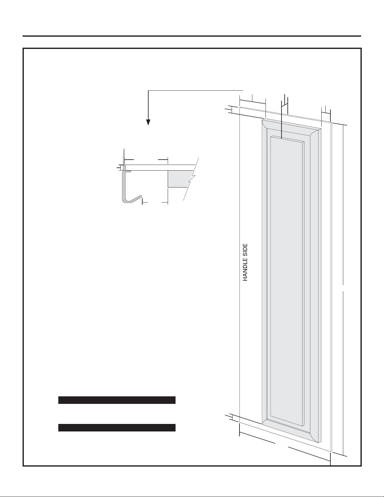
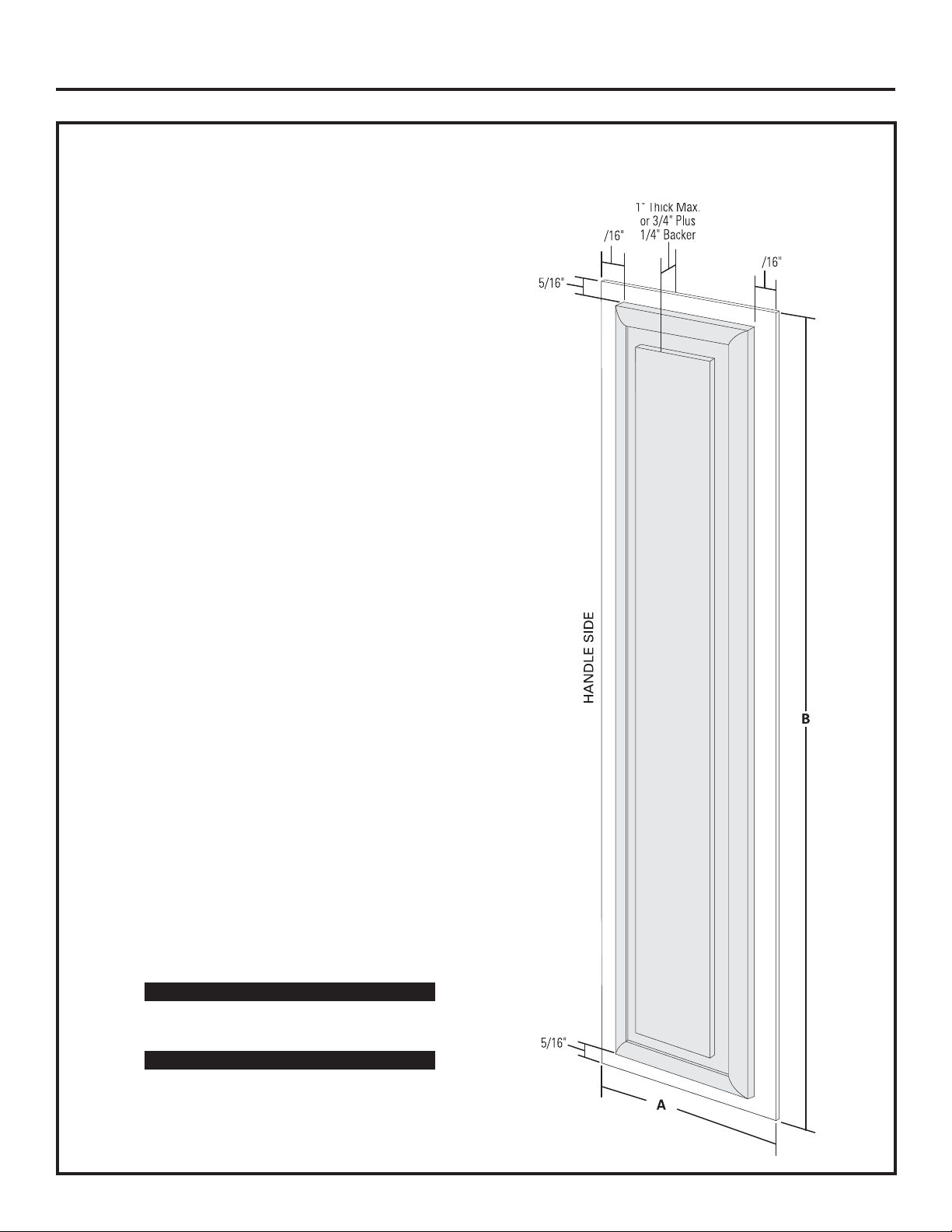
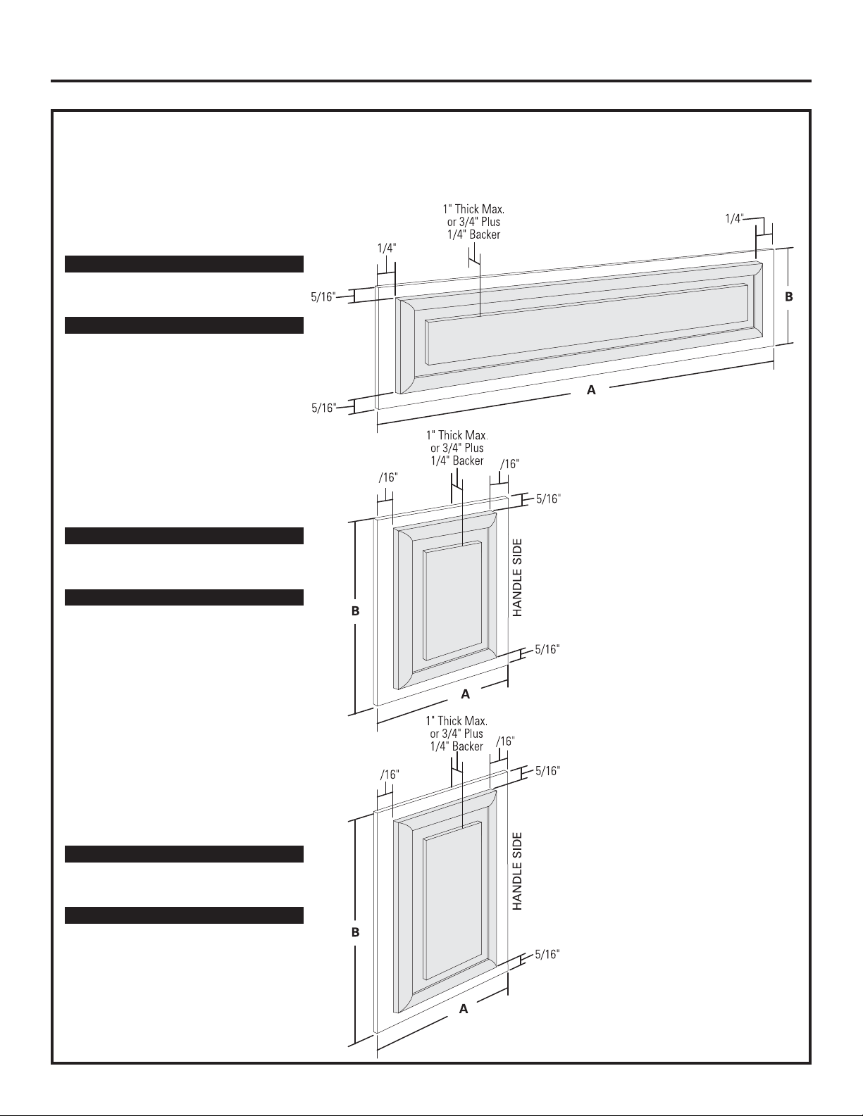
3/4” FRAMED CUSTOM WOOD PANELS WITH PRE-INSTALLED HANDLES
Secured to a 1/4” finished backer panel. This design provides a framed appearance.
1" Thick Max.
or 3/4" Plus
3-1/8"
Fresh Food Panel
5/16"
Required for Optimal
Handle Clearance
3-1/8" Min.
1/4" Max.
2-1/2"
1/4" Backer
3/8"
42” Models A B
1/4” Backer Panel 22-5/16” 67-7/8”
3/4” Overlay Panel 18-13/16” 67-1/4”
48” Models A B
1/4” Backer Panel 26-7/16” 67-7/8”
3/4” Overlay Panel 22-15/16” 67-1/4”
B
5/16"
A
23
Installation Instructions
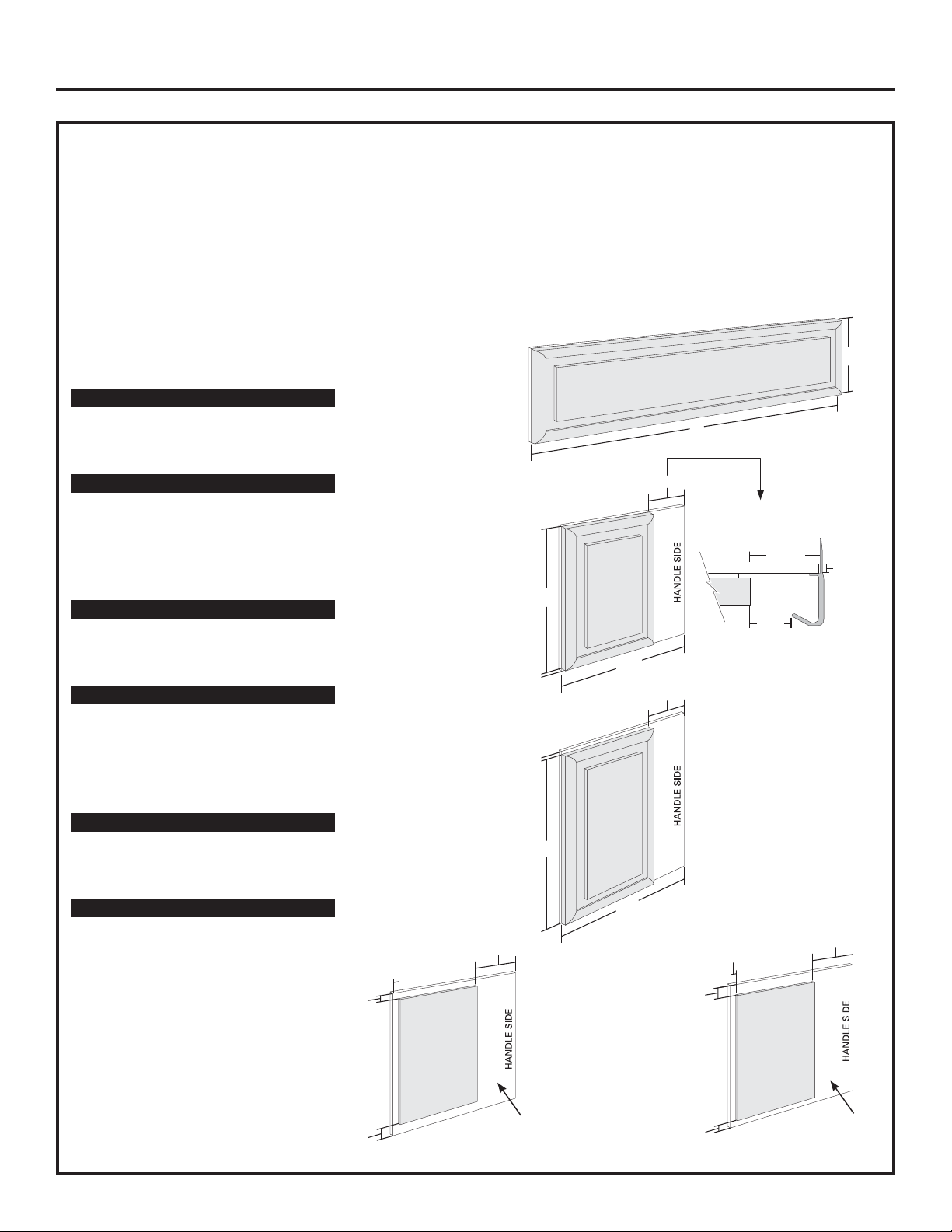
3/4” FRAMED CUSTOM WOOD PANELS WITH PRE-INSTALLED HANDLES
Secured to a 1/4” finished backer panel. This design provides a framed appearance.
Grille Panel
42” Models A B
1/4” Backer Panel 39-15/16” 10-3/4”
3/4” Overlay Panel 39-7/16” 10-1/8”
48” Models A B
1/4” Backer Panel 45-15/16” 10-3/4”
3/4” Overlay Panel 45-7/16” 10-1/8”
Upper Freezer Panel
42” Models A B
1/4” Backer Panel 16-7/16” 17-13/16”
3/4” Overlay Panel 12-15/16” 17-3/16”
48” Models A B
1/4” Backer Panel 18-7/16” 17-13/16”
3/4” Overlay Panel 14-15/16” 17-3/16”
5/16"
5/16"
1/4"
3/8"
1" Thick Max.
or 3/4" Plus
1/4" Backer
1" Thick Max.
or 3/4" Plus
1/4" Backer
3-1/8"
5/16"
A
Required for Optimal
1/4"
B
Handle Clearance
3-1/8" Min.
1/4"
Max.
B
5/16"
2-1/2"
Lower Freezer Panel
42” Models A B
1/4” Backer Panel 16-7/16” 35-1/8”
3/4” Overlay Panel 12-15/16” 34-1/2”
48” Models A B
1/4” Backer Panel 18-7/16” 35-1/8”
3/4” Overlay Panel 14-15/16” 34-1/2”
A
1" Thick Max.
or 3/4" Plus
1/4" Backer
3/8"
B
3-1/8"
5/16"
5/16"
A
24
Installation Instructions
3/4” FULL-WIDTH OVERLAY CUSTOM PANELS WITH PRE-INSTALLED HANDLES
This panel design provides a nearly trimless appearance.
Fresh Food Panel
Assemble the spacer panel
onto the finished backer
panel. Allow 1/2” clearance
on the top, bottom and
hinge side. Allow 3-5/8” on
the handle side. Secure the
panels with glue. Be sure to
observe clearances shown
on all sides.
Secure the overlay
panel to the assembled
backer/spacer panel.
Use glue and screws.
Countersink screws
into the backer panel.
3-5/8"
Spacer
Panel
1/2"
1/2"
Required for Optimal
Handle Clearance
1/4"
Max.
3-1/8" Min.
3-1/8"
2-1/2"
B
Finished
Backer
Panel
42” Models A B
1/4” Backer Panel 22-5/16” 67-7/8”
0.10” Spacer Panel 18-3/16” 66-7/8”
3/4” Overlay Panel 19-5/16” 68-1/8”
48” Models A B
1/4” Backer Panel 26-7/16” 67-7/8”
0.10” Spacer Panel 22-5/16” 66-7/8”
3/4” Overlay Panel 23-7/16” 68-1/8”
1/2"
A
25
Installation Instructions
3/4” FULL-WIDTH OVERLAY CUSTOM PANELS WITH PRE-INSTALLED HANDLES
This panel design provides a nearly trimless appearance.
Assemble the spacer panel onto the backer panel. Allow 1/2” clearance on all four sides of the grille spacer
panel. Allow 1/2” clearance on the top and hinge side, 15/16” on the bottom and 3-5/8” on the handle side of
the upper freezer door panel. Allow 15/16” on the top, 1/2” clearance on the bottom and hinge side and 3-5/8”
on the handle side of the lower freezer door panel. Secure the panels with glue. Be sure to observe clearances
on all sides.
Secure the appearance panel to the assembled backer/spacer panel. Use glue
and screws. Countersink screws into the backer panel.
Grille Panel
42” Models A B
1/4” Backer Panel 39-15/16” 10-3/4”
0.10” Spacer Panel 38-15/16” 9-3/4”
3/4” Overlay Panel 40-3/16” 11”
A
B
48” Models A B
1/4” Backer Panel 45-15/16” 10-3/4”
0.10” Spacer Panel 44-15/16” 9-3/4”
3/4” Overlay Panel 46-3/16” 11”
Upper Freezer Panel
42” Models A B
1/4” Backer Panel 16-7/16” 17-13/16”
0.10” Spacer Panel 12-5/16” 16-3/8”
3/4” Overlay Panel 13-7/16” 17-5/8”
48” Models A B
1/4” Backer Panel 18-7/16” 17-13/16”
0.10” Spacer Panel 14-5/16” 16-3/8”
3/4” Overlay Panel 15-7/16” 17-5/8”
Lower Freezer Panel
42” Models A B
1/4” Backer Panel 16-7/16” 35-1/8”
0.10” Spacer Panel 12-5/16” 33-11/16”
3/4” Overlay Panel 13-7/16” 34-15/16”
48” Models A B
1/4” Backer Panel 18-7/16” 35-1/8”
0.10” Spacer Panel 14-5/16” 33-11/16”
3/4” Overlay Panel 15-7/16” 34-15/16”
Upper Freezer Panel
Spacer Assembly
3-5/8"
1/2"
5/16"
5/16"
3-1/8"
Required for Optimal
Handle Clearance
3-1/8" Min.
B
2-1/2"
A
3-1/8"
B
A
Lower Freezer Panel
1/4"
Max.
Spacer Assembly
3-5/8"
1/2"
1/2"
15/16"
Spacer
Panel
Backer Panel
26
Finished
15/16"
1/2"
Spacer
Panel
Finished
Backer Panel
Installation Instructions
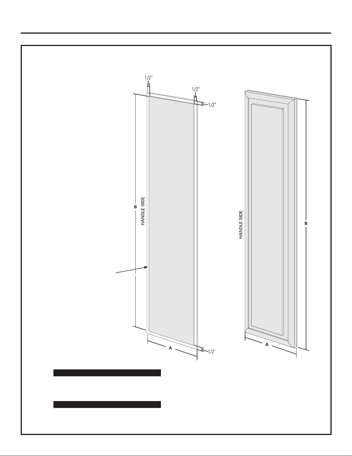
3/4” FRAMED CUSTOM WOOD PANELS WITH CUSTOM HANDLES
Secured to a 1/4” finished backer panel. This design provides a framed appearance.
Fresh Food Panel
3
3
42” Models A B
1/4” Backer Panel 22-5/16” 67-7/8”
3/4” Overlay Panel 21-15/16” 67-1/4”
48” Models A B
1/4” Backer Panel 26-7/16” 67-7/8”
3/4” Overlay Panel 26-1/16” 67-1/4”
27
Installation Instructions
3/4” FRAMED CUSTOM WOOD PANELS WITH CUSTOM HANDLES
Secured to a 1/4” finished backer panel. This design provides a framed appearance.
Grille Panel
42” Models A B
1/4” Backer Panel 39-15/16” 10-3/4”
3/4” Overlay Panel 39-7/16” 10-1/8”
48” Models A B
1/4” Backer Panel 45-15/16” 10-3/4”
3/4” Overlay Panel 45-7/16” 10-1/8”
Upper Freezer Panel
42” Models A B
1/4” Backer Panel 16-7/16” 17-13/16”
3/4” Overlay Panel 16-1/16” 17-3/16”
48” Models A B
1/4” Backer Panel 18-7/16” 17-13/16”
3/4” Overlay Panel 18-1/16” 17-3/16”
Lower Freezer Panel
42” Models A B
1/4” Backer Panel 16-7/16” 35-1/8”
3/4” Overlay Panel 16-1/16” 34-1/2”
3
3
3
3
48” Models A B
1/4” Backer Panel 18-7/16” 35-1/8”
3/4” Overlay Panel 18-1/16” 34-1/2”
28
Installation Instructions
3/4” FULL-WIDTH OVERLAY CUSTOM PANELS WITH CUSTOM HANDLES
This panel design provides a nearly trimless appearance.
Fresh Food Panel
Assemble the spacer panel
onto the finished backer
panel. Allow 1/2” clearance
on all sides. Secure the
panels with glue. Be sure to
observe clearances shown
on all sides.
Secure the overlay
panel to the assembled
backer/spacer panel.
Use glue and screws.
Countersink screws
into the backer panel.
Finished
Backer
Panel
42” Models A B
1/4” Backer Panel 22-5/16” 67-7/8”
0.10” Spacer Panel 21-13/16” 66-7/8”
3/4” Overlay Panel 22-5/16” 68-1/8”
Spacer
Panel
48” Models A B
1/4” Backer Panel 26-7/16” 67-7/8”
0.10” Spacer Panel 25-13/16” 66-7/8”
3/4” Overlay Panel 26-7/16” 68-1/8”
29
 Loading...