

Page 1
GE Consumer & Industrial
TECHNICAL SERVICE GUIDE
Profi le 42" and 48" Built-In Side by
Side Refrigerators
MODEL SERIES:
PSB42LSRBV
PSB42LGRWV
PSB42LGRBV
PSB48LSRBV
PSB48LGRWV
PSB48LGRBV
PUB # 31-9125 11/04
Page 2

IMPORTANT SAFETY NOTICE
The information in this service guide is intended for use by
individuals possessing adequate backgrounds of electrical,
electronic, and mechanical experience. Any attempt to repair a
major appliance may result in personal injury and property
damage. The manufacturer or seller cannot be responsible for the
interpretation of this information, nor can it assume any liability in
connection with its use.
WARNING
To avoid personal injury, disconnect power before servicing
this product. If electrical power is required for diagnosis or test
purposes, disconnect the power immediately after performing the
necessary checks.
RECONNECT ALL GROUNDING DEVICES
If grounding wires, screws, straps, clips, nuts, or washers used to
complete a path to ground are removed for service, they must be
returned to their original position and properly fastened.
GE Consumer & Industrial
Technical Service Guide
Copyright © 2004
All rights reserved. This service guide may not be reproduced in whole or in part
in any form without written permission from the General Electric Company.
– 2 –
Page 3

Table of Contents
3-Way Valve ...................................................................................................................................36
Auger Motor ...................................................................................................................................27
Casters and Leveling .....................................................................................................................21
Components ..................................................................................................................................18
Component Locator Views .............................................................................................................12
Component Resistance Values ......................................................................................................8
Compressor ...................................................................................................................................35
Control Features ............................................................................................................................10
Cube Motor and Cube Reed Switch ..............................................................................................28
Defrost Cycles ...............................................................................................................................40
Diagnostic Mode ............................................................................................................................52
Dispenser Control Panel ................................................................................................................29
Dispenser Heater ...........................................................................................................................34
Dispenser Switch ...........................................................................................................................33
Doors .............................................................................................................................................18
Door Closer Assembly ...................................................................................................................20
Door Switches ................................................................................................................................38
Door Water Line Replacement .......................................................................................................34
Drain Pan .......................................................................................................................................21
Drier ...............................................................................................................................................36
Duct Door Assembly ......................................................................................................................32
Evacuation and Charging Procedure .............................................................................................16
Fans ...............................................................................................................................................41
Freezer Evaporator Assembly .......................................................................................................44
Freezer Evaporator Components ..................................................................................................47
Freezer Heater Testing ..................................................................................................................43
Fresh Food Evaporator Assembly .................................................................................................48
Fresh Food Evaporator Components ............................................................................................50
Fresh Food Heater Testing ............................................................................................................43
Heat Exchanger .............................................................................................................................35
Icemaker Controls ..........................................................................................................................11
Icemaker Fill Tube and Heater .......................................................................................................26
Ice Bin and Icemaker .....................................................................................................................26
Ice Dispenser .................................................................................................................................30
Illustrated Parts ..............................................................................................................................58
Installation Example 42" Model ......................................................................................................5
Interior Airfl ow ................................................................................................................................17
Interior Lights .................................................................................................................................38
Introduction ....................................................................................................................................4
Machine Compartment Access Door .............................................................................................18
Main Switch ...................................................................................................................................34
Muffl ers ..........................................................................................................................................36
Nomenclature ................................................................................................................................9
Power Control Board (PCB) ...........................................................................................................22
Refrigerant Flow ............................................................................................................................14
Refrigeration Components .............................................................................................................13
Refrigeration System .....................................................................................................................13
Replacing the Freezer or Fresh Food Evaporator ........................................................................51
Schematics ....................................................................................................................................56
Service Diagnostics ......................................................................................................................52
Technical Data ...............................................................................................................................8
Terminal Block Panel .....................................................................................................................24
Thermistors ....................................................................................................................................39
Troubleshooting Notes ..................................................................................................................55
arranty ........................................................................................................................................72
W
Water Valve and Water Tank .........................................................................................................30
– 3 –
Page 4

Introduction
The new Profi le Built-In Side by Side refrigerator has the following features:
Separate freezer and fresh food evaporators are recessed into the machine compartment for
•
increased effi ciency and interior space savings.
3-Way valve directs refrigerant fl ow where needed.
•
High-and low-side sealed system muffl ers quiet the operation.
•
Inverter is built into the power control board (PCB).
•
Combined dispenser and temperature control board provides customer control and test mode
•
operations.
Dispenser cube motor and cam replaces solenoid-operated cube mechanism.
•
Room ambient thermistor aids power control board (PCB) operation.
•
Component electrical testing is performed at the machine compartment-mounted terminal block.
•
Rear leveling mechanism is front-adjustable.
•
– 4 –
Page 5
Installation Example 42" Model
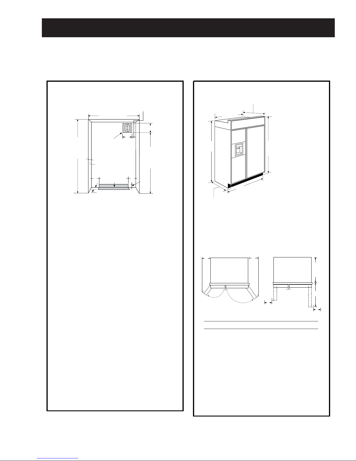
THE INSTALLATION SPACE
3"
*Finished Width
7"
84 1/2" max
83 1/2" min
Finished
Opening
Electrical
Area
24"
5"
Water Supply
3 1/2"
*The finished cutout width must be:
41-1/2" for 42" models
Water and Electrical Locations
The opening must be prepared with the
electrical and water supply located as shown.
The cutout depth must be 24"
The refrigerator will project forward, slightly
beyond adjacent cabinets, depending on
your installation.
Additional Specifications
• A 120 volt, 60Hz, 15 or 20 amp power
supply is required. An individual properly
grounded branch circuit or circuit breaker
is recommended. Install a properly
grounded 3-prong electrical receptacle
recessed into the back wall. Electrical must
be located on rear wall as shown.
Note: GFI (ground fault interrupter) is not
recommended.
• Water line can enter the opening through
the floor or rear wall. The water line
installed should be 1/4" O.D. copper tubing
or GE SmartConnect
cold water line and water connection
location. The line should be long enough
to extend to the front of the refrigerator.
Installation of an easily accessible shutoff
valve in the water line is required.
5"
74"
From Floor
to Bottom
of Electrical
5"
3 1/2"
™
tubing between the
DIMENSIONS AND CLEARANCES
25-3/8" Case Depth
41"
Case Width
*81-3/4"
at Rear
42" Frame-to-Frame
Depth Including
Handles 26-7/8"
*84" From
Floor to
Top Frame
Product Clearances
These refrigerators are equipped with a 2
position door stop. The factory set 130° door
swing can be adjusted to 90° if clearance to
adjacent cabinets or walls is restricted.
130° Door Swing 90° Door Swing
A
B
D
Models A B C D
42" 12-3/16" 16" 24" 4"
Allow minimum clearances for Freezer
door (Dimension A) and Fresh Food door
(Dimension B) for a full 130° door swing
and to allow for drawer removal.
Four inch (4") minimum clearance is required
when door swing is adjusted to 90°. If the 90°
door stop position is used, drawer access is
maintained, but drawer removal is restricted.
*Shipping height
The front height
may be adjusted
from 83-1/2" to 84-1/2"
by adjusting front and
rear leveling legs a
maximum of 1".
23-7/8"
Behind
Frame
C
D
– 5 –
Page 6
Positioned
Anti-Tip
Bracket
Wall Stud
(Behind
Drywall)
Wood Screws
Mounted into
Vertical
Wood Studs
36"
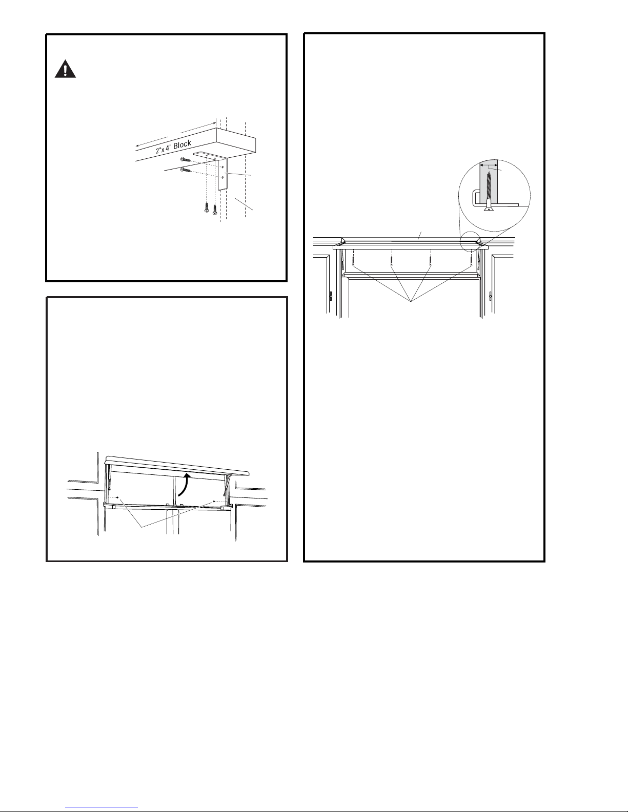
INSTALL ANTI-TIP BRACKETS
WARNING:
The refrigerator is Top-Heavy and must be secured
to prevent the possibility of tipping forward.
•
Cut a 2" x 4" wood block 36" long,
and secure the block to
the mounting
brackets
provided,
using #12 or
#14 wood screws.
•
Secure the
brackets with
wood block to the
back wall so that it is
82" (or the rear installation height) from the
finished floor. Use #12 or #14 wood screws.
Screws must penetrate at least 1" into vertical
•
wall studs.
ANTI-TIP
PRECAUTIONS
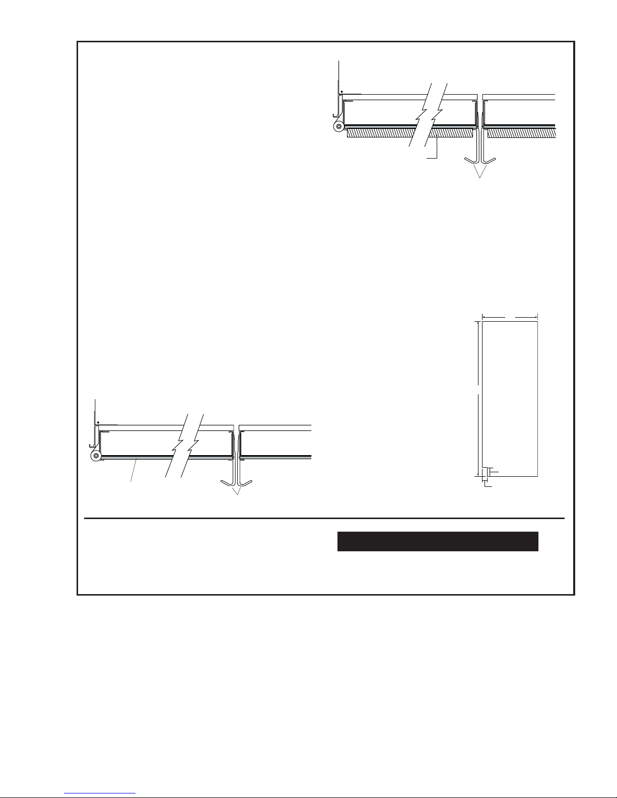
ALTERNATE ANTI-TIP
PRECAUTIONS
SKIP THIS STEP WHEN USING ANTI-TIP
BRACKETS
All Profile built-in refrigerators are Top-Heavy.
They must be secured to prevent the possibility
of tipping forward. Use this alternative method
to secure the refrigerator whenever steel wall
studs are encountered.
3/4"
Min.
Side View
Top Case Trim
Top Case Trim
SECURE REFRIGERATOR
TO CABINETS
Whenever possible, perform this step for
anti-tip security.
The refrigerator must be secured to prevent
tipping.
• Raise the grille panel to access case trim.
• Drive a screw through the trim and into the
adjacent cabinet using holes provided.
• Follow the same procedure on the opposite
side.
Raise Grille Panel
to Stop Position
Drive Screws
Through Case Trim Into
Adjacent Cabinets
Install (4) 1-1/2" Drywall Screws
Through Trim and Into Soffit
or 3/4" Min. Wood Brace
• Adjust height of refrigerator to match
installation cutout opening 83-1/2" to
84-1/2". The refrigerator must be level and
plumb with cabinets. The top case trim at
the front is 2-1/8" higher than the rear and
will overlap upper cabinets or cabinet trim.
• Open grille panel to access the top case trim.
Use a 3/16" bit to drill 4 evenly spaced
•
clearance holes through the metal top
case trim.
Use a 1/16" bit to drill pilot holes through
•
the metal clearance holes and into wood
soffit. The holes should be centered in the
soffit or a 3/4" minimum wood brace. The
brace spanning the enclosure must be
securely fastened to cabinets on both sides.
Install four 1-1/2" drywall screws into the
•
pilot holes.
– 6 –
Page 7
CUSTOMIZATION BASICS:
Framed Or Custom Panels
Stainless Steel Wrapped Models
42" wide model - PSB42LSRBV
Trimmed Models
42" wide models - PSB42LGRWV, PSB42LGRBV
Stainless Steel Wrapped Refrigerators
Stainless Steel wrapped refrigerators have
wrapped doors and grille panels, and beveled
edges. These models are shipped ready for
installation.
Door Handles
The handles can be used to accommodate
both framed or custom panels.
Trimmed Refrigerators
Trimmed refrigerators are designed to be
customized with decorative panels. Field
installed custom door and grille panels are
required. You may install 1/4" thick custom
panels from your cabinet manufacturer. The
decorative panel slides into the factory
installed trim. Or, order black and white
accessory panels from your Profile dealer.
3/4" Custom Panel
Door Handles
Side Panels
Side panels (not supplied) must be used
whenever the sides of the refrigerator will
be exposed.
24"
*84"
Framed Panel
Door Handles
Accessory Panels
White and black accessory panels are
available from your Profile dealer. Panels are
cut to size and ready to install.
*Depending on
installation height.
Models White Black
Acrylic Acrylic
PSB42LGRWV PSPK42DWW
PSB42LGRBV PSPK42DBB
*3" to 4"
1-1/2"
– 7 –
Page 8
Technical Data
PSB42LGRBV, PSB42LGRWV, PSB42LSRBV PSB48LGRBV, PSB48LGRWV, PSB48LSRBV
DISCONNECT POWER CORD BEFORE SERVICING
IMPORTANT - RECONNECT ALL GROUNDING DEVICES
All parts of this appliance capable of conducting
electrical current are grounded. If grounding
wires, screws, straps, clips, nuts or washers
used to complete a path to ground are removed
for service, they must be returned to their
original position and properly fastened.
CAUTION
To avoid personal injury when servicing the
condensing unit, stand on a ladder which will
give enough support to allow removal of the top
panel and safely allow access to service the unit.
ELECTRICAL SPECIFICATIONS
Max Defrost Control
w/No Door Openings........................16 hrs
Evap Defrost Thermistor........68°F (FZ)..63°F (FF)
Electrical Rating: 115V AC 60 HZ.............5.4 amp
Maximum Current Leakage......................0.75 mA
Maximum Ground Path Resistance...............0.1 Ω
Energy Consumption Model 42........50.5 KWh/mo
Energy Consumption Model 48......53.75 KWh/mo
COMPONENT RESISTANCE VALUES
FF fan motor ……………………..............1600 Ω ± 20%
FZ fan motor ………………………….......1600 Ω ± 20%
Condenser fan motor ………………........1600 Ω ± 20%
Auger motor ………………………..............3.7 Ω ± 15%
Cube motor …………………………….....2091 Ω ± 10%
Cover motor ……………………………....2091 Ω ± 10%
Defrost heater FZ ……..................................44 Ω ± 7%
Drain heater FZ ..........................................377 Ω ± 7%
Sub-heater FZ ………...............................1322 Ω ± 7%
Defrost heater FF .......................................120 Ω ± 7%
Drain heater FF …......................................440 Ω ± 7%
Fill-tube heater .……….............................2645 Ω ± 7%
Dispenser heater (Recess)………………..1889 Ω ± 7%
Compressor (between the different
phase) …………….....................11. 7 Ω ± 7% / 1 phase
3- way valve …………………………..40 ± 4 Ω/ 1 phase
Water valve (Ice maker) …………...............180 Ω ± 7%
Water valve (Dispenser) ..………................325 Ω ± 7%
IMPORTANT SAFETY NOTICE
This information is intended for use by individuals
possessing adequate backgrounds of electrical,
electronic and mechanical experience. Any
attempt to repair a major appliance may result
in personal injury and property damage. The
manufacturer or seller cannot be responsible for
the interpretation of this information, nor can it
assume any liability in connection with its use.
NO LOAD PERFORMANCE
Control Position 37-0°F and
Ambient Temperature of: 70°F 90°F
Fresh Food °F 37-42 36-43
Frozen Food °F (-2)-2 (-2)-5
Percent Running Time, %..........35-45 65-75
REFRIGERATION DIAGNOSIS
To access the low pressure side of the system,
install a WJ56X61 valve only on the process tube
extending from the compressor case.
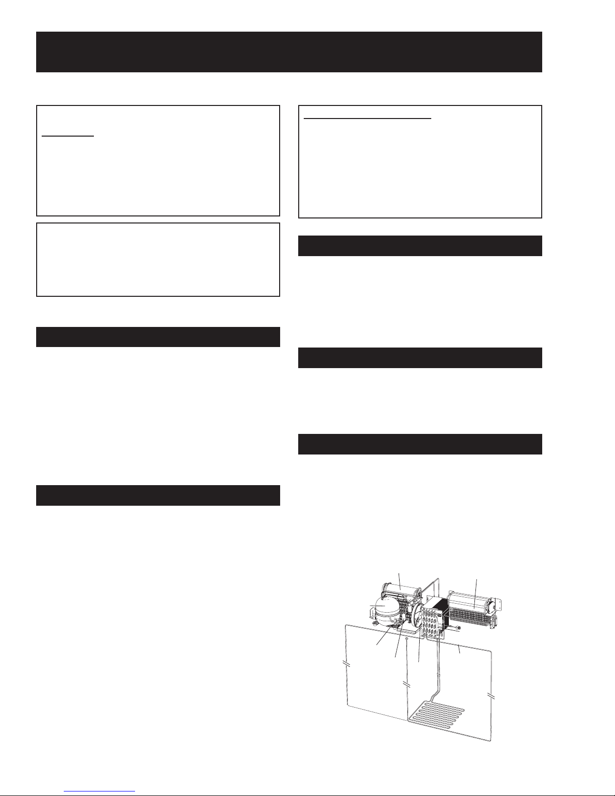
REFRIGERATION SYSTEM
Refrigerant Charge (R134a).......................8.11 ounces
Compressor........................................738-1270 BTU/hr
Minimum Compressor Capacity
Vacuum...........................................................26 inches
Minimum Equalized Pressure
@70°F...............................................................66 PSIG
@90°F...............................................................74 PSIG
Freezer
Compressor
Compressor
Suction Tube
Suction Tube
Freezer
Evaporator
Evaporator
Muffler
Dryer
Condenser
Condenser
Fan
Fan
Fresh Food
Fresh Food
Evaporator
Evaporator
Dryer
Condenser
Condenser
Loop
Loop
– 8 –
Page 9
Nomenclature
P S
Brand/Product
P - P r o fi l e
Style
S - Side by Side
Confi guration
B - Built-In
Size
42 - 42 Inches Wide
48 - 48 Inches Wide
Feature Pack
B
42
L
G
R
A
W
Trim
W - White Disp Trim
B - Black Disp Trim
Engineering
A - Initial Design
B - 1st Revision
C - 2nd Revision
D - 3rd Revision
Etc.
Model Year
R - 2004
Icemaker/Exterior
G - 1 Year Filter
S - Stainless Steel
V
Door Type
V - Visor Handle
Nomenclature
The
nomenclature
plate is located
at the top of
the fresh food
section on the
right-side wall.
It contains
the model and
serial numbers
and specifi es
the minimum
installation clearances, electrical voltage,
frequency, maximum amperage rating, and
refrigerant charge.
Mini-Manual
The mini-manual is located behind the
grille panel at the top of the refrigerator.
When service is completed, return the
mini-manual to its original location for
future use.
Serial Number
The fi rst two numbers of the serial number
identify the month and year of manufacture.
Example: AG123456S = January, 2004
A - JAN 2005 - H
D - FEB 2004 - G
F - MAR 2003 - F
G - APR 2002 - D
H - MAY 2001 - A
L - JUN 2000 - Z
M - JUL 1999 - V
R - AUG 1998 - T
S - SEP 1997 - S
T - OCT 1996 - R
V - NOV 1995 - M
Z - DEC 1994 - L
The letter designating
the year repeats every
12 years.
Example:
T - 1974
T - 1986
T - 1998
– 9 –
Page 10
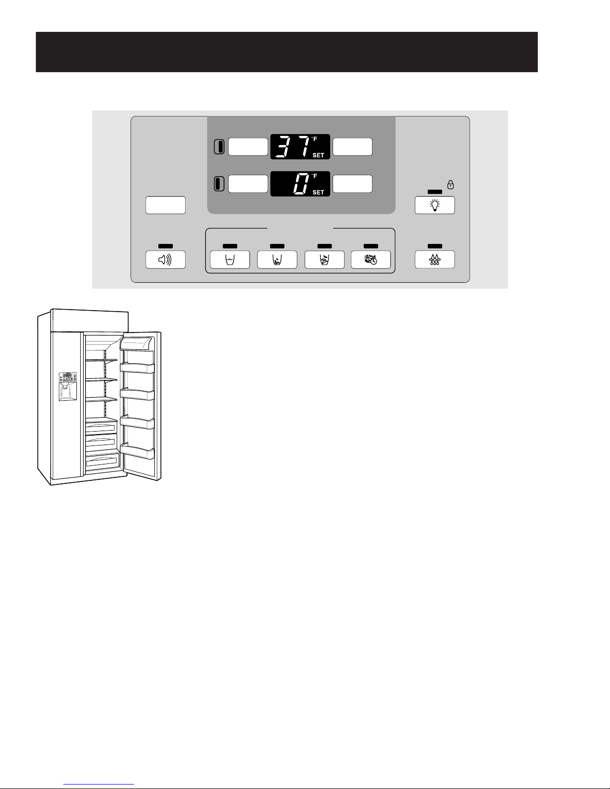
DISPLAY
The temperature controls are preset in the factory at 37°F for the
refrigerator compartment and 0°F for the freezer compartment. Allow
24 hours for the temperature to stabilize to the preset recommended
settings.
The temperature controls can display both the SET temperature
as well as the actual temperature in the refrigerator and freezer.
The actual temperature may vary slightly from the SET temperature
based on usage and operating environment.
NOTE: The refrigerator is shipped with protective film covering the
temperature controls. If this film was not removed during installation,
remove it now.
To change the temperature, press and release the
WARMER or COLDER button. SET will illuminate in
the display, as well as the set temperature. To
change the temperature, tap either the WARMER or
COLDER button (while SET is illuminated) until the
desired temperature is displayed. Refrigerator
temperatures can be adjusted between 34°F and
47°F and the freezer temperatures can be adjusted
between –6°F and +8°F.
Once the desired temperature has been set,
the temperature display will clear after 10 seconds.
To display the temperature, the DISPLAY TEMP
button may be tapped.
Several adjustments may be required. Each time you
adjust controls, allow 24 hours for the refrigerator to
reach the temperature you have set.
TEMP
Control Features
ADJUST TEMPERATURE
COLDER WARMER
REFRIGERATOR
COLDER WARMER
FREEZER
37º F IS RECOMMENDED
0º F IS RECOMMENDED
ICE DISPENSER
HOLD FOR
3 SECS
TO ACTIVATE
LOCK
LIGHT
QUICK ICECUBEDCRUSHEDWATERDOOR ALARM
RESET FILTER
HOLD 3 SECS
– 10 –
Page 11
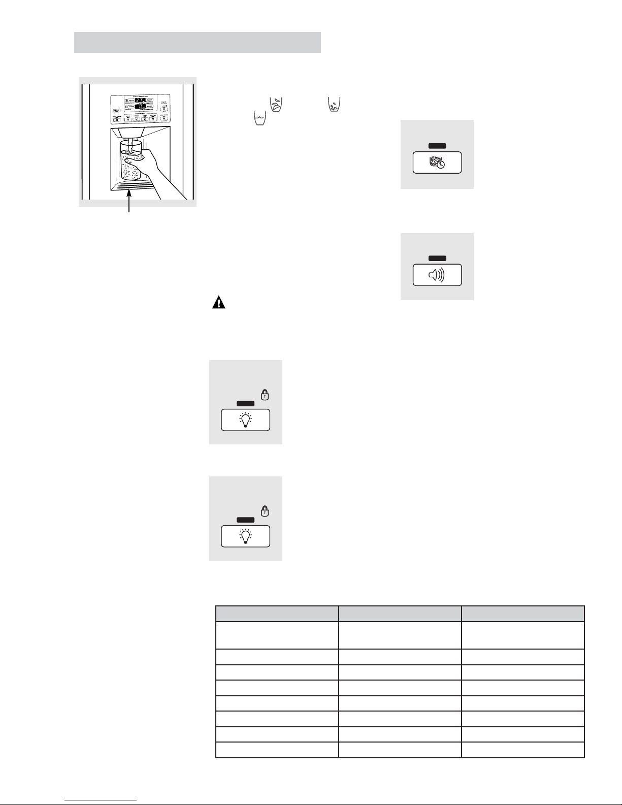
To Use the Dispenser
Select CUBED , CRUSHED
or WATER .
Press the glass gently against the middle
of the dispenser pad.
The spill shelf is not self-draining.
To reduce water spotting, the shelf and
its grille should be cleaned regularly.
If no water is dispensed when the
refrigerator is first installed, there may be
air in the water line system. Press the
dispenser arm for at least two minutes to
remove trapped air from the water line
and to fill the water system. To flush out
impurities in the water line, throw away
the first six glassfuls of water.
CAUTION:
Never put fingers
or any other objects into the ice crusher
discharge opening.
Locking the Dispenser
Press the LOCK/LIGHT
button for 3 seconds
to lock the dispenser
and control panel. To
unlock, press and hold
the button again for
3 seconds.
Dispenser Light
This button turns
the night light on the
dispenser on and off.
The light also comes
on when the dispenser
pad is pressed. If this
light burns out, it should
be replaced with a 6 watt
12V maximum bulb.
Quick Ice
When you need ice
in a hurry, press this
button to speed up ice
production. This will
increase ice production
for the following
48 hours or until you
press the button again.
Door Alarm
To turn the Door Alarm
on, press the DOOR
ALARM button once.
The ACTIVE light will
come on. To turn it off,
press it again. When the
DOOR ALARM is active,
the ACTIVE light will
flash if you open the
door and beep if you
keep the door open for
more than 2 minutes.
The light goes out and
the beeping stops when
you close the door.
Spill Shelf
Icemaker Controls
QUICK ICE
DOOR ALARM
Display after power failure:
After a power failure, the
display will reset based
on freezer temperature.
If the freezer temperature
is below 40°F, the display
will retain the settings
prior to power loss. The
chart at the right describes
the possible settings.
HOLD FOR
3 SECS
TO ACTIVATE
LOCK
LIGHT
HOLD FOR
3 SECS
TO ACTIVATE
LOCK
LIGHT
Control Function Freezer<40°F Freezer>40°F
Refrigerator Set
Temperature
Freezer Set Temperature Previous Setting Default (0°F)
Door Alarm Previous Setting Previous Setting
Dispenser Option Previous Setting Default (Crushed Ice)
Quick Ice Previous Setting OFF
Reset Filter Previous Setting Previous Setting
Lock Previous Setting Previous Setting
Dispenser Light Previous Setting OFF
– 11 –
Previous Setting Default 37°F
Note: When QUICK ICE is selected,
the freezer temperature operates
at -9°F for 48 hours or until QUICK
ICE is pressed again. There is no
change of temperature on the
display panel.
In the event of a power loss, if the
freezer temperature is above 40°F,
Quick Ice will not restart. Below
40°F, the refrigerator will return to
the Quick Ice mode.
Page 12
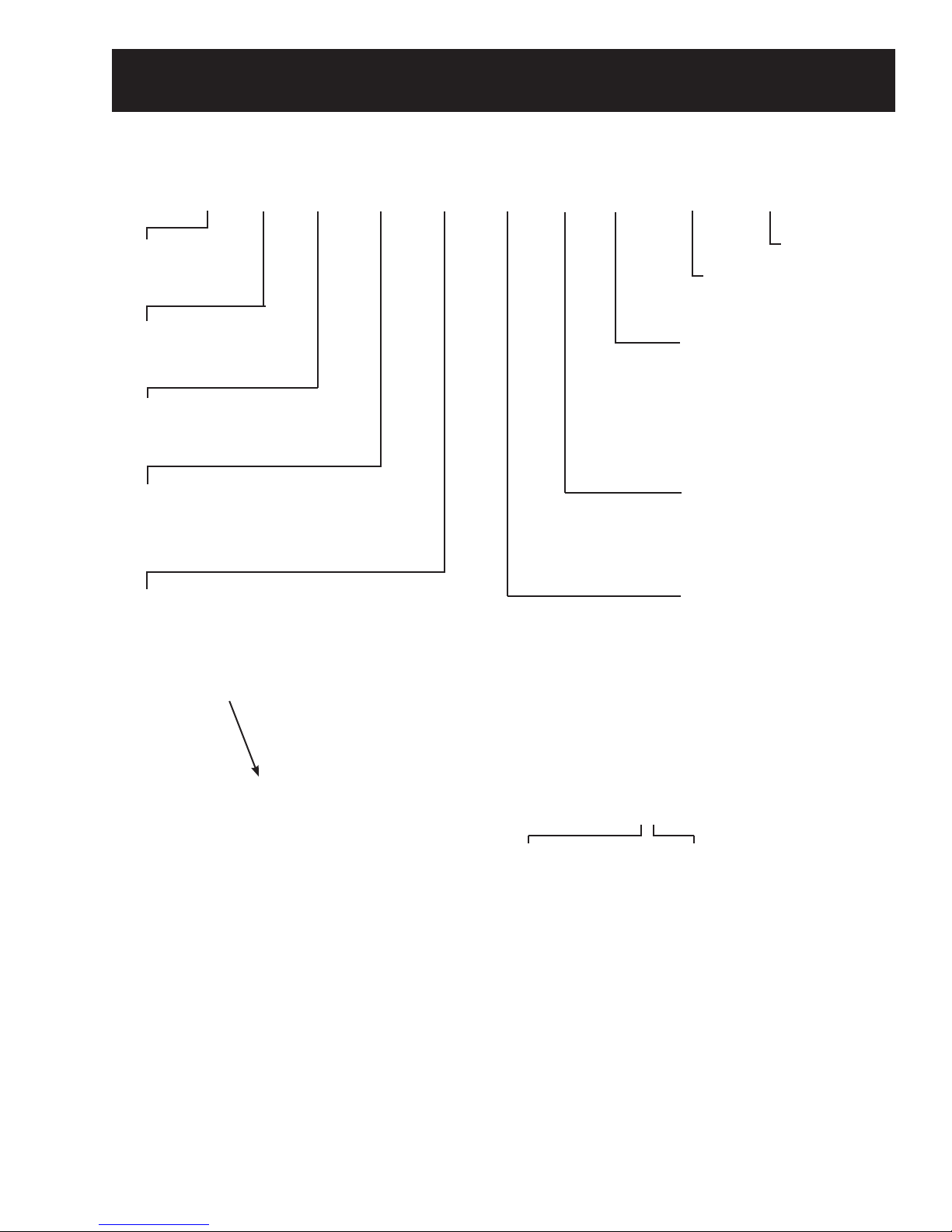
Machine Compartment
Water Valve
Component Locator Views
Power Control Board
Te rminal Block
Condenser
Main Power Switch
*The 3-way valve is located behind the condenser front plate.
Refrigerator (Bottom View, Drain Pan Removed)
Rear Leveler
Drier
Water Lines
3-Way Valve*
Door Closer
Freezer Defrost Drain Tube
Fresh Food Defrost Drain Tube
Rear Leveler
Drain Pan Loop
Door Closer
– 12 –
Page 13
r
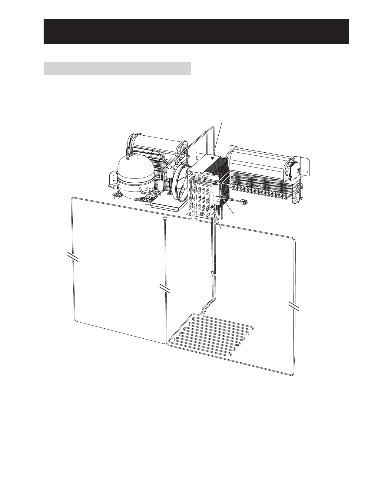
Refrigeration Components
Refrigeration System
Freezer Evaporator
Compressor
Condenser Loop
and Fan
Condenser
Fresh Food Evaporato
3-Way Valve
Drier
and Fan
Drain Pan
Heater
– 13 –
Page 14
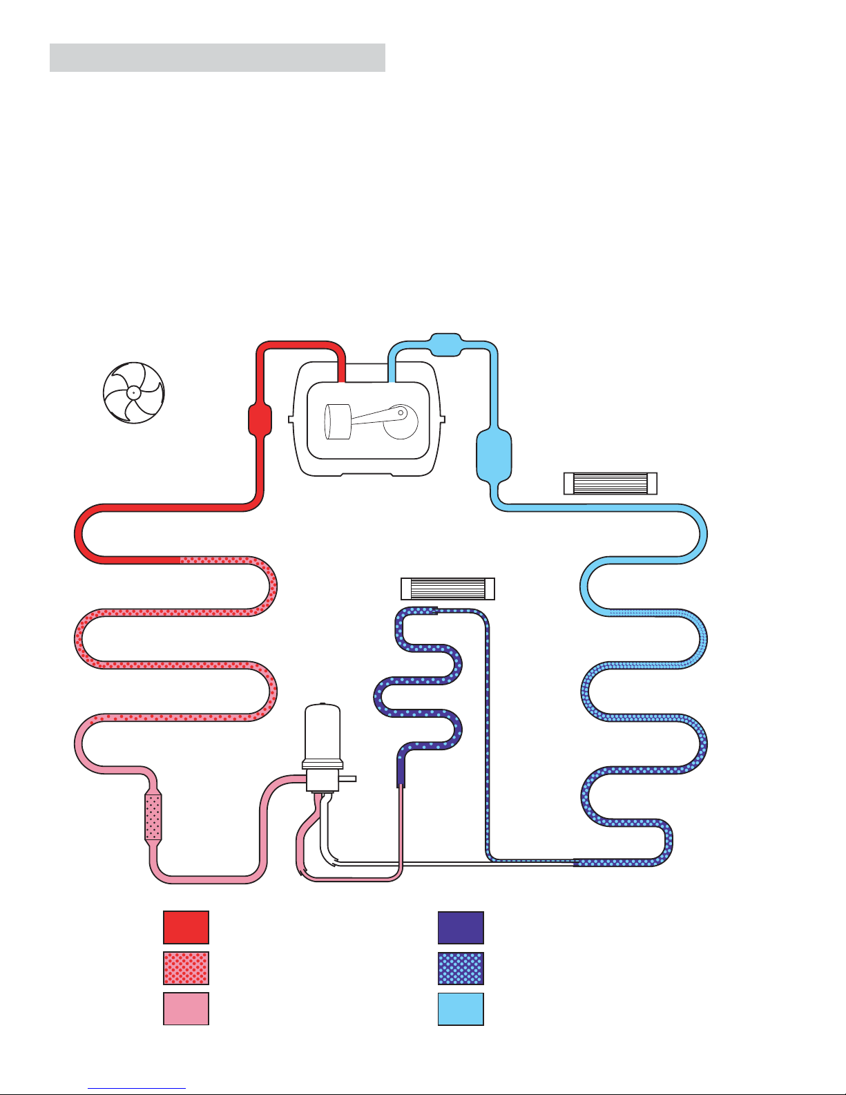
Refrigerant Flow
The compressor compresses R134a refrigerant,
raising its pressure and temperature. Refrigerant
vapor is pumped out the compressor discharge,
down through the drain pan loop, up through
the condenser coil, around the condenser loop,
through the drier, and into the 3-way valve. By
the time the refrigerant has reached the 3-way
valve, it has completely condensed into a liquid.
Depending upon whether the main control board
opens the 3-way valve to the freezer evaporator
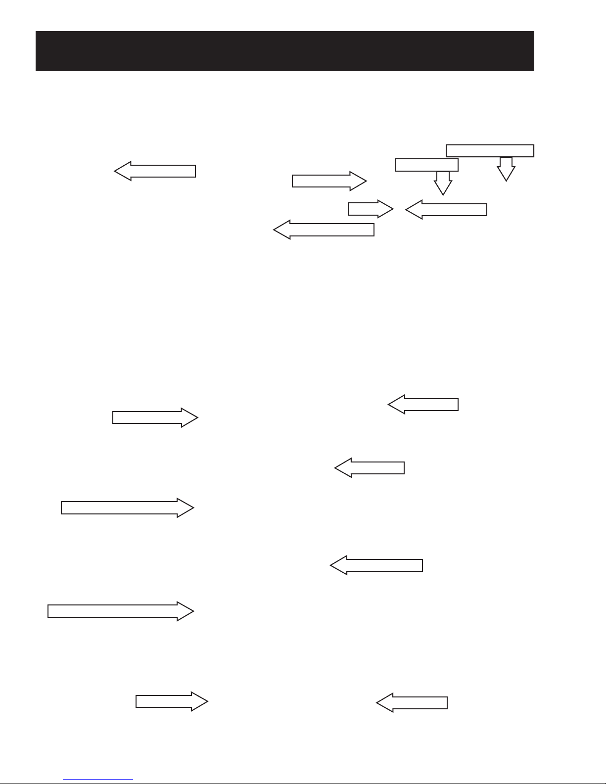
FRESH FOOD AND FREEZER SECTION COOLING
Condenser Fan
or the fresh food and freezer evaporators,
refrigerant fl ows through the appropriate capillary
tube and into the evaporator. As the high pressure
liquid passes through the capillary and enters the
low pressure evaporator, it quickly expands and
evaporates. During evaporation, the refrigerant
absorbs heat, becoming cold. At the outlet of the
freezer evaporator, an accumulator captures any
remaining liquid, allowing only low pressure vapor
to return to the compressor through the suction
line.
Muffler
Condenser
Muffler
3-Way
Valve
Compressor
Fresh Food
Evaporator
Accumulator
Freezer Fan
Fresh Food Fan
Freezer
Evaporator
Jumper
Tube
Drier
High Pressure Vapor
Mix of Liquid and Vapor
High Pressure Liquid
Capillary
Low Pressure Liquid
Mix of Liquid and Vapor
Low Pressure Vapor
– 14 –
Page 15
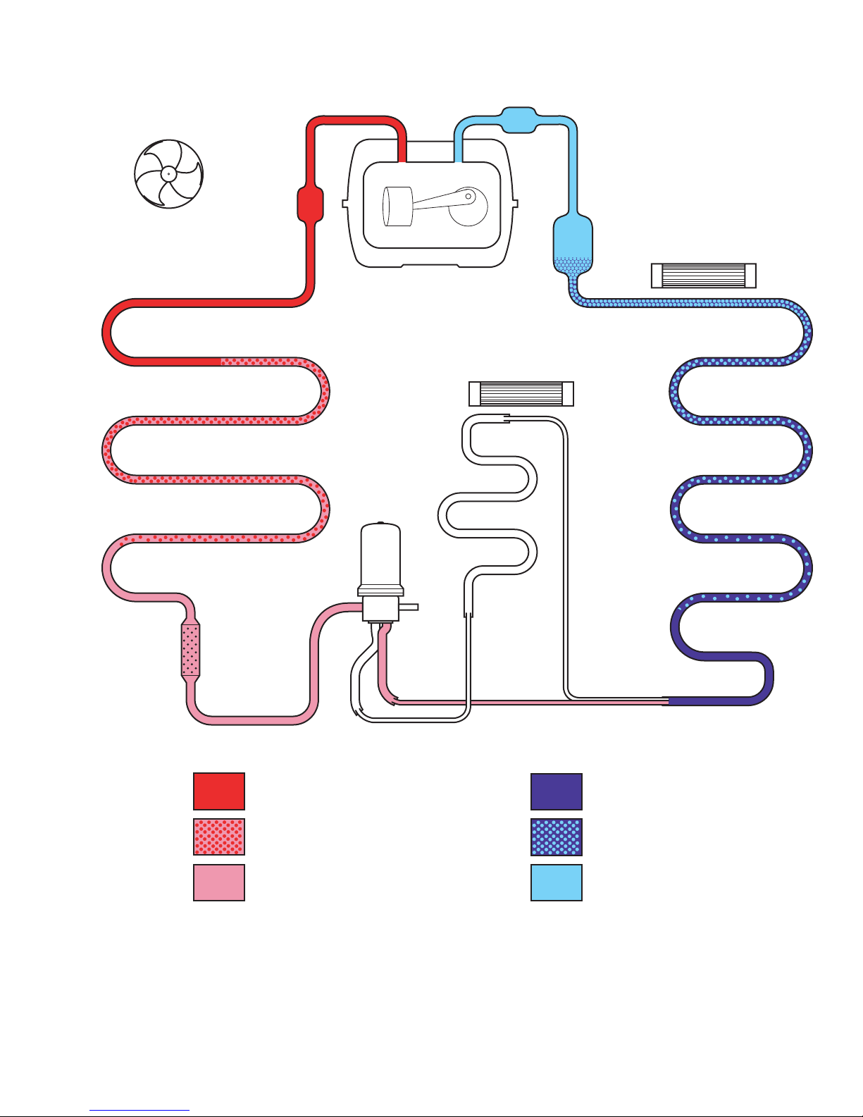
Condenser Fan
FREEZER SECTION COOLING
Muffler
Condenser
Muffler
3-Way
Valve
Compressor
Fresh Food
Evaporator
Accumulator
Freezer Fan
Fresh Food Fan
Freezer
Evaporator
Jumper
Tube
Drier
Capillary
High Pressure Vapor
Mix of Liquid and Vapor
High Pressure Liquid
Note: The refrigerator will operate with the 3-way valve set for freezer only or set for fresh food and
freezer. There is no 3-way valve setting for fresh food only. If the fresh food thermistor is not satisfi ed,
but the freezer thermistor is satisfi ed, the refrigerator will still operate with the 3-way valve set in the
fresh food and freezer mode.
Low Pressure Liquid
Mix of Liquid and Vapor
Low Pressure Vapor
– 15 –
Page 16

Evacuation and Charging Procedure
WARNING:
• Before cutting or using a torch on refrigerant
tubes, recover the refrigerant from the system
using approved recovery equipment.
• Never charge new refrigerant through the
purge valve. This valve is always located on
the high pressure side of the system.
• Never apply heat from any source to a
container of refrigerant. Such action will cause
excessive pressure in the container.
• Always wear goggles when working with
refrigerants and nitrogen holding a charge in
some replacement parts. Contact with these
gases may cause injury.
1. Attach the hose from the R-134a charging
cylinder to the process tube port on the
compressor.
4. Open the ball valve. Recover the purge/
sweep charge using the recovery pump and
the refrigerator compressor until a 20-in.
vacuum is attained. Close the ball valve and
remove the recovery hose.
5. Charge the system with the exact amount of
R-134a refrigerant specifi ed.
6. Disconnect the power cord to the refrigerator.
This allows the pressure to equalize. After 3
to 5 minutes, the low-side pressure will be
positive and then the hose-to-charging port
can be disconnected.
7. Using an electronic leak detector, check
all brazed joints and both schrader ports.
Reinstall caps to schrader ports.
2. Evacuate the system to a minimum 20-in.
vacuum using the refrigerator compressor and
recovery pump, which is attached to the new
drier assembly.
3. Turn off the recovery pump. Close the ball
valve on the hose connected to the high-side
port connection. Add 3 ounces of R-134a
refrigerant to the system. Let the refrigerator
operate and circulate the refrigerant for 5
minutes.
– 16 –
Page 17
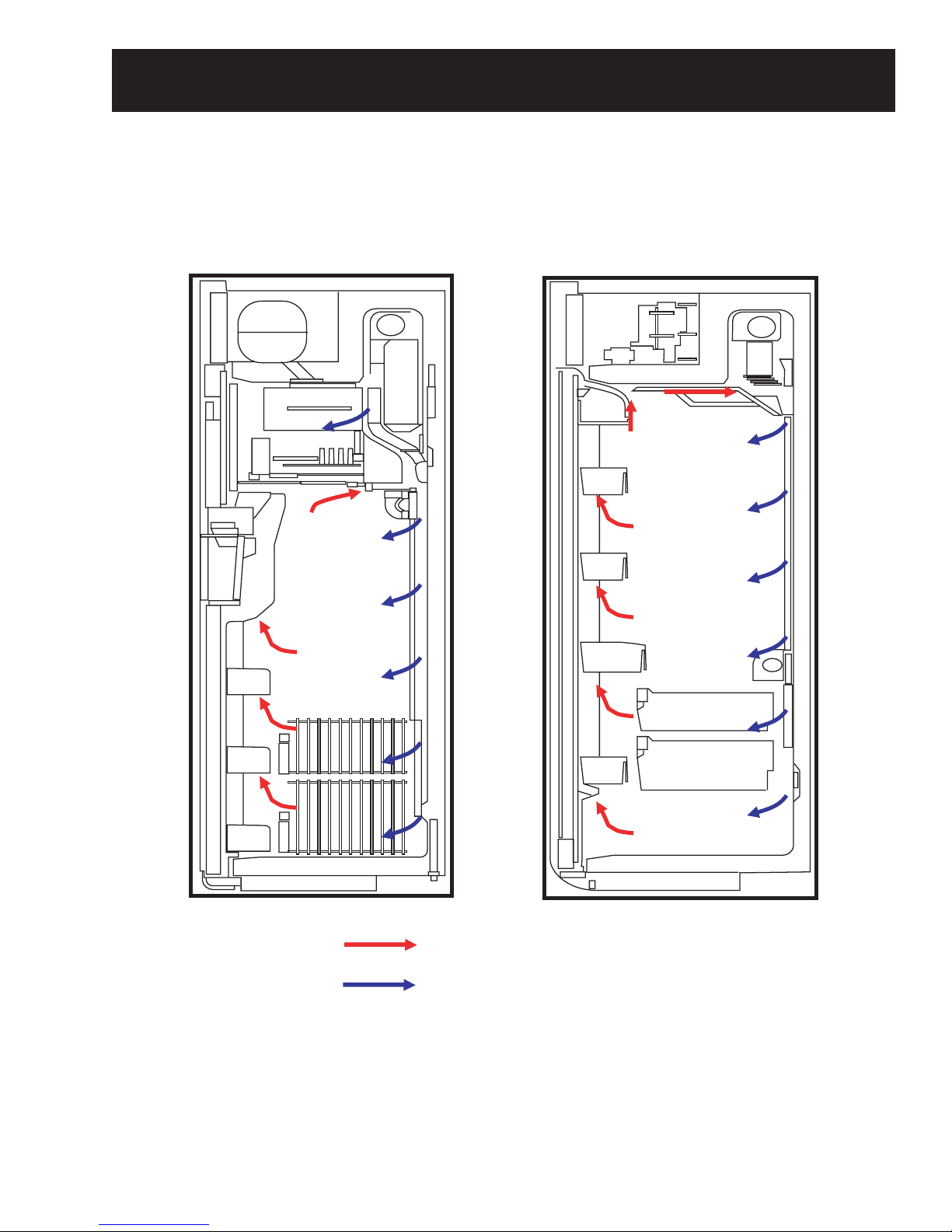
Interior Airfl ow
Freezer Air Flow
Fresh Food Air Flow
Note: The fans are extremely quiet. Check for airfl ow at the icemaker air duct in the freezer and the top
tower vent in the fresh food section. Fans turn off when the doors are opened (DC door switches control
operation) and delay 10 seconds before restarting when the doors are closed again. The freezer door
switch controls only the freezer fan. The fresh food door switch controls both the fresh food and freezer
fan operation.
Warm Circulated Air
Fresh Cold Air
– 17 –
Page 18
Components
Machine Compartment Access Door
The machine compartment access door is held in
place by 2 hinges and 2 gas shocks.
To remove the machine compartment access
door:
1. Remove the grille panel.
2. Remove the gas shocks from the cabinet:
a. Insert a small screwdriver under the
retainer clip.
b. Pull the retainer inward to dislodge the gas
shock from the pivot ball.
3. Remove the 2 screws from both hinges, then
remove the machine compartment access
door.
Door Alignment
The freezer door is nonadjustable. The fresh
food door has an adjustment screw at the bottom
hinge. Use a 7/32-in. socket or open-end wrench
to turn the adjusting screw clockwise to raise the
door, or counterclockwise to lower the door. A
nylon plug, imbedded in the threads of the pin,
prevents the pin from turning, unless a tool is
used.
Note: Raising the fresh food door too high will
cause the upper hinge to bind on the machine
compartment access door.
Adjusting Screw
Gas Shock
Clip
Doors
The doors are of one-piece construction with
foamed-in insulation.
The inner and outer door panels cannot be
separated and must be replaced as an assembly.
Note: On trimmed models, the maximum weight
for the fresh food door panel is 70 pounds. The
maximum weight for the freezer door panel is 30
pounds.
Door Stop
The refrigerator has a 2-position door stop. When
space does not allow the door to swing open fully
to 130°, the stop can be adjusted to a 90° door
swing. The pin is factory installed in the 130°
location. To change the stop location, use a fl athead screwdriver to move the stop pin.
Interior
90
130
Hinge
Door
– 18 –
Page 19
Door Removal
Door Gaskets
WARNING: Use the appropriate safety equipment
and lifting techniques. Two persons may be
required for door removal.
Caution: Use wood or a heavy plastic sheet to
protect the fl oor where the door will be placed.
1. Remove the 8-mm mounting screw from the
5
hinge arm link using a
Mounting Screw
/16-in. or 8-mm socket.
The fresh food and freezer doors have magnetic
gaskets that create a positive seal to the front
of the steel cabinet. The cabinet has magnets
around the perimeter and center mullion under
the front edge.
Shown With Plastic Liner Removed
Cabinet Edge
Condenser Loop
Cabinet Magnet
2. If removing the freezer door, shut off the
water supply and disconnect the water line
and electrical connectors. If removing the
refrigerator door, disconnect the static ground
wire from the grounding screw.
Screw
Ground Wire
The magnetic door gaskets are secured to the
doors by a barbed edge that locks into a retainer
channel.
To remove and replace the door gasket:
1. Starting at any corner, pull the old gasket out
of the retaining channel.
2. Soak the new gasket in warm water to make it
pliable.
3. Push the barbed edge of the gasket into the
retainer channel.
3. Remove the upper hinge.
4. Lift the door up and out.
– 19 –
Page 20
Door Closer Assembly
Each door is equipped with a door closer
assembly that provides a smooth closing action
and prevents the door from being slammed shut.
The assembly is connected to the bottom hinge.
When the door is open to a 90° position, it will
automatically close. Beyond this position, the
door will stay open.
2. Ensure the opening on the white nylon
support faces towards the inside of the
cabinet.
To remove the door closer assembly:
1. Remove the toe plate.
2. Remove the 8-mm mounting screw.
3. Insert a small screwdriver into the retaining
clip at the bottom of the shock absorber and
lift up (see photo).
4. Using a large screwdriver, lever the shock
absorber off the pivot ball as shown.
Retaining Clip
3. Make sure the door closer assembly support
is fully seated in the bracket to ensure
alignment of ball and socket.
Shown from Installation Viewpoint
5. Remove the door closer assembly by pulling it
forward. Make certain to retain the white nylon
shock absorber support.
To install the door closer:
1. To make installation of the shock absorber
easier, secure the white nylon support to the
cylinder body with electrical tape .
Ta pe
White Nylon Support
– 20 –
Page 21
Casters and Leveling
Drain Pan
Leveling is provided by 2 adjustable rear levelers
and 2 front leveling legs. The unit has 4 fi xed
casters that are used to position the refrigerator.
When adjusting the rear levelers, turn the
7
/16-in. hex nut, located above the front casters,
clockwise to lower, or counterclockwise to raise.
When adjusting the front legs, use an open-end
wrench and turn the front legs clockwise to lower,
or counterclockwise to raise.
Note: The rear levelers and the 4 casters are
each attached to the refrigerator with four 10-mm
screws. To access the screws, raise or tilt the
refrigerator.
Bottom Right Half of Refrigerator Shown
Hex Nut
The drain pan can be removed for cleaning
purposes.
Drain pan removal:
1. Remove the toe plate.
2. To remove the drain pan, grasp the center of
the drain pan and pull outward.
3. To install the drain pan, slide it back into
position so the rear and front mounting tabs
engage.
4. Firmly push the drain pan into position.
Ta b
Ta b
Leveling Leg
Rear Leveler
Warning: Use the appropriate safety equipment and
lifting techniques. Two persons may be required.
Drain Pan
Ta b
Ta b
The defrost water in the pan is evaporated by use
of a submersible serpentine coil, which is part of
the sealed system. The tubing is copper coated
with black paint.
Drain Pan Loop
– 21 –
Page 22

Power Control Board (PCB)
The PCB housing is attached to the rear wall of the machine compartment by 2 Phillips-head screws.
The PCB is enclosed inside a housing and mounted on the right side of the machine compartment
behind the terminal block panel.
Noise Filter
The noise fi lter is mounted in a
recessed area in the PCB housing.
To access the noise fi lter:
1. Remove 3 screws from the
fi lter cover.
2. Disconnect the 2 lead wires.
3. Remove the 13-mm hex nut at
the end of the noise fi lter that
holds the ground wire in place.
To check the noise fi lter, look for
the epoxy molding to be broken
or burnt by heat or a power surge.
The noise fi lter resistance should
be approximately 500K Ω between
the black and red wires.
Noise Filter
– 22 –
Page 23

Control Board Connector Locator
r
r
Common
Freezer Fan VDC
Condenser Fan VDC
Freezer Fan Feedback
Condenser Fan Feedback
Refrigerator Fan Feedback
Refrigerator Fan VDC
CN72 CN90
CN71
1
CN70
1
FZ Defrost *
FF Defrost **
Dispenser Heater
Neutral (from noise filter)
Duct Door Motor
Dispenser Water Valve
L1 (from choke)
CN71
1
CN70
1
3-Way Valve
1
1
CN72 CN90
Temperature Control & Display
1
CN50
1
1
CN50
Common
Freezer Door Switch
1
1
Cube Reed Switch
Common
Freezer Thermistor
Refrigerator Door Switch
Refrigerator Thermistor
Freezer Evaporator Thermistor
Refrigerator Evaporator Thermisto
CN30
CN30
CN31
Common
Dispenser Switch
Duct Door Cam Switch #1
Duct Door Cam Switch #2
Dispenser Light
CN31
1
1
External Thermisto
CN02 Pin 11
Auger Motor
Cube Motor
Neutral (from noise filter)
L1 (from choke)
Compressor Overload
Compressor Overload
* FZ Defrost - Freezer defrost circuit consists of the defrost heater, bi-metal thermostat,
** FF Defrost - Fresh food defrost circuit consists of the defrost heater, bi-metal thermostat,
CN10
1
CN10
1
1
CN12
1
CN12
CN04
1
1
CN04 ***
1
Compressor
drain pan and tube heater and suction line drain pan heater.
drain pan heater and icemaker fill tube heater.
Compressor
Compressor
*** CN04 on the control board connects to the CN8 connector on the terminal block panel.
– 23 –
Page 24

Terminal Block Panel
The terminal block panel is located on the right side of the machine compartment and attached to the
PCB housing cover. The terminal block consists of AC and DC wire harness connectors.
To access the wire harness connectors, remove the 4 Phillips-head screws that hold the front cover in
place.
Front Cover
Terminal Block Panel with Cover Removed
DC CONNECTIONS
CN2
101213
3
5
6
7
4
CN3
23
1
5
6
4
CN4
345678
CN5
5
6
3
4
2
CN6
567
23
1
Connector Locator
AC CONNECTIONS
1
89
2
1
CN1
CN7
34
2
678
10
2
1
5
9
CN8
9101112131415
2
1
16 15 14 13
5
678
12
11
234
10
1
CN9
23
1
4
Note: Throughout the service guide, reference to the terminal block connectors may or may not contain
a zero (i.e., CN3 and CN03 are the same connector.)
– 24 –
Page 25

Connector Description
DC CONNECTIONS AC CONNECTIONS
CON PIN DESCRIPTION WIRE COLOR CON PIN DESCRIPTION WIRE COLOR
CN2 1 Condenser Fan Feedback
CN2 2 Condenser Fan VDC
CN2 3 Condenser Fan Common Gray
CN2 4 3-Way Valve Red CN7 1 FZ Defrost (Switched L1) Brown
CN2 5 3-Way Valve Black CN7 2 FZ Defrost (Neutral) Orange
CN2 6 FZ Door Switch White/Yellow CN7 3 Icemaker (L1) Black
CN2 7 FZ & FF Door Switch (Common) Gray CN7 4 Icemaker (Water) (Switched L1) Blue
CN2 8 3-Way Valve Blue CN7 5 Icemaker (Neutral) Red
CN2 9 3-Way Valve Yellow CN7 6 Auger & Cube Motor (Switched Neutral) P/Blue
CN2 10 3-Way Valve Orange CN7 7 Cube Motor (Switched L1) Light Blue
CN2 11 Empty CN7 8 Auger Motor (Switched L1) Pink
CN2 12 External Thermistor Red CN7 9 FZ Light (L1) Black
CN2 13 FF Door Switch White/Blue CN7 10 FZ Light (Switched Neutral) White/Blue
CN2 14 Empty CN7 11 Empty
CN3 1 Duct Door Cam Switch #1 Blue
CN3 2 Duct Door Cam Switch #2 Purple CN8 1 Water Valve (Icemaker) (Switched L1) Purple
CN3 3 Dispenser Switch White CN8 2 Water Valve (Dispenser) (Switched L1) Gray
CN3 4 Dispenser Components (Common) Gray CN8 3 Water Valve (Neutral) (Icemaker & Dispenser) Red
CN3 5 Dispenser Light Light Blue CN8 4 Duct Door Motor & Dispenser Heater (Neutral) Red
CN3 6 Empty CN8 5 Dispenser Heater (Switched L1) Brown
CN4 1 Temperature Control & Display Black CN8 7 Compressor (3 Phase) Black
CN4 2 Temperature Control & Display Brown CN8 8 Compressor (3 Phase) Purple
CN4 3 Temperature Control & Display Red CN8 9 Empty
CN4 4 Temperature Control & Display Orange CN8 10 FZ Door Switch (Auger & Cube Motor) P/Blue
CN4 5 Temperature Control & Display Yellow CN8 11 FF Door Light Switch (Switched Neutral) Yellow
CN4 6 Temperature Control & Display Pink CN8 12 FZ Door Light Switch (Switched Neutral) Orange
CN4 7 Temperature Control & Display Blue CN8 13 FF Door Light Switch (L1) Black
CN4 8 Temperature Control & Display Purple CN8 14 Compressor Overload (Pwr Supply Neutral) Light Blue
CN4 9 Temperature Control & Display Gray CN8 15 Compressor Overload (Pwr Supply Neutral) Light Blue
CN4 10 Temperature Control & Display White CN8 16 Compressor (3 Phase) Blue
CN4 11 Temperature Control & Display Light Blue
CN4 12 Temperature Control & Display White/Black CN9 1 FF Defrost (Switched L1) White
CN4 13 Temperature Control & Display White/Red CN9 2 FF Defrost (Neutral) Red
CN4 14 Temperature Control & Display White/Blue CN9 3 FF Lights (Switched L1) Light Blue
CN4 15 Temperature Control & Display White/Yellow CN9 4 FF Lights (Neutral) Red
CN4 16 Empty CN9 5 Empty
CN5 1 Empty CN9 7 Empty
CN5 2 FF Fan & Thermistors (Common) Gray CN9 8 Empty
CN5 3 FF Thermistor Yellow CN9 9 Empty
CN5 4 FF Evaporator Thermistor Pink
CN5 5 FF Fan Feedback Brown
CN5 6 FF Fan VDC Orange
Red
Light Blue
1 L1 (Switched thru Master Switch) Black
CN1
2 Neutral (Switched thru Master Switch) Red
CN1
CN7 12 Empty
CN8 6 Duct Door Motor (Switched L1) White
CN9 6 Empty
CN6 1 FZ Fan Feedback Black
CN6 2 FZ Fan VDC Yellow
CN6 3
CN6 4 Empty
FZ Fan, Thermistors & Cube Switch
(Common)
Gray
– 25 –
Page 26

Icemaker
Feeler Arm
Power Switch
Green
Power Light
Ice Bin and Icemaker
Ice Bin
The ice bin holds approximately 7 pounds of ice,
equivalent to about 230 cubes.
The ice bin can be removed by lifting it upward,
to clear the tabs holding the bin in place, then
pulling forward.
To remove the icemaker:
Remove the ice bin. Remove 2 front screws
1.
that hold the ice bin shelf in place.
2. Pull the shelf forward to access the icemaker
plug, then unplug the icemaker.
3. Remove the 2 screws that hold the icemaker
in place. Remove the icemaker.
Ta bs
Icemaker
The icemaker is mounted to the upper left wall
of the freezer cabinet. Under normal operating
conditions, the icemaker is capable of producing
approximately 4.3 pounds of ice in a 24-hour
period. During
QUICK ICE, the icemaker is capable
of producing 5.5 pounds of ice in a 24-hour
period.
I = On
0 = Off
Check for 120 VAC to the icemaker at CN07 on
the terminal block between pin #3 (power) and
pin # 5 (neutral).
Icemaker Fill Tube and Heater
To remove the icemaker fi ll tube and heater:
1. Remove the ice bin and icemaker (see Ice
Bin and Icemaker).
2. Remove the elbow from the end of the fi ll
tube.
Elbow
– 26 –
Page 27

3. In the machine compartment, remove the
2 screws from the fi ll tube cover (located
beneath the water valve to the left of
compressor).
Auger Motor
The auger motor is mounted to the ice bin shelf.
To access the auger motor:
Fill Tube Cover
4. Disconnect the fi ll tube water line, then
remove the fi ll tube from the cabinet.
Heater Wiring
Fill Tube
5. The heater is attached to the fi ll tube and can
be separated from the tube by removing the
tape and foil.
1. Remove the ice bin (see
Icemaker).
Ice Bin and
2. Remove the 2 screws that hold the ice bin
shelf in place.
3. Pull the shelf forward to expose the electrical
connectors.
4. Disconnect the auger motor wire harness and
remove the ice bin shelf.
5. Unsnap the auger motor cover to access the
auger motor. The auger motor is held in place
by 4 Phillips-head mounting screws.
Heater
Note: The heater is supplied with 120 VAC only
during the fresh food evaporator defrost cycle.
The fi ll tube heater is in parallel with the fresh
food evaporator defrost heater and the fresh food
drain heater. The fi ll tube heater is also referred to
as the "PIPE HEATER" on some schematics and
"SUB-HEATER FF" in early mini-manuals.
When the fresh food defrost cycle is initiated,
check for 120 VAC at CN09 on the terminal block,
between pin #1 and pin #2.
WHITE
RED
CN09
1
2
BIMETAL
THERMOSTAT
FF DEFROST HEATER 120
FF DRAIN HEATER 440
FILL TUBE HEATER 2.6K
Rear View
Auger Motor Cover
Ice Bin Shelf
The auger motor operates on 120 VAC and has a
resistance of approximately 3.7 Ω.
To check the supply voltage to the auger motor,
select CUBED on the ice dispenser control panel,
then press the dispenser pad to close the switch.
Check for 120 VAC at CN07 on the terminal block
between pin #6 and pin #8.
– 27 –
Page 28

Cube Motor and Cube Reed Switch
The cube motor replaces the cube solenoid
assembly and is mounted to the ice container
shelf.
To access the cube motor and reed switch:
1. Unsnap the cover.
2. Remove the 2 screws that attach the cube
motor assembly to the ice bin shelf.
3. Disconnect the wire harness.
Auger Motor
To check the cube reed switch:
1. Select CUBED on the ice dispenser control
panel, then press the dispenser pad to close
the switch.
2. Check for 5 VDC at CN06 on the terminal
block between pin #3 and pin #7.
3. Select
CRUSHED on the ice dispenser control
panel, then check for 0 VDC at the same
pin location with the dispenser switch in the
closed position.
CN06
GRAY
EMI Shield
Lift Arm
Lift Cam
Cube Motor
The EMI shield prevents electrical interference
from the auger motor from affecting the operation
of the cube motor reed switch. Make sure the
shield is in place before replacing the cover.
The cube motor operates on 120 VAC and has a
resistance of approximately 2K Ω.
Note: The auger motor thermal overload is in the
cube motor circuit.
CN07
GEARED MOTOR-CUBE
AUGER MOTOR
1
2
5
6
P/BLUE
LIGHT BLUE
PINK
6
7
8
BROWN
RED
ORANGE
Shown with Motor Removed
Magnet
Switch
F-SENSOR
F-DEF-SENSOR
CUBE REED S/W
Cam
Note: The motor, cam, reed switch, and harness
are replaced as a complete assembly.
To check the supply voltage to the cube motor,
select
CUBED on the ice dispenser control panel,
then press the dispenser pad to close the switch.
Check for 120 VAC at CN07 on the terminal block
between pin #6 and pin #7.
The cube reed switch is mounted to the cube
motor housing. A small magnet is attached to the
motor lift cam. The magnetic operation of the reed
switch informs the power control Board (PCB) of
the position of the cube motor lift cam.
– 28 –
Page 29

Dispenser Control Panel
The dispenser control panel contains the control
module and room ambient thermistor. The panel
is available in black or white. Stainless steel
models come with black trim. To remove the
dispenser control panel on stainless steel front
models, insert a fl at-bladed screwdriver and lift
the frame outward to release the 15 retaining
hooks from the freezer door. Protect the freezer
door with cloth or tape to prevent marring the
surface.
To remove the dispenser frame on trimmed
models, remove the door handle fi rst, then slide
out the top panel. The dispenser cover can then
be removed by pulling it away from the door front.
Testing the Dispenser Control Pads
Run the HMI Self-Test 0 6 (see
Diagnostics). If any portion of the test fails, the
Service
control module pads can be tested at the CN04
connector on the terminal block (see Terminal
Block Panel
).
Disconnect the CN04 connector and read the
resistance between the wires to the control
module. When each pad is pressed, a reading of
approximately 10K Ω should be present between
the pins as shown in the chart below.
As an example, when the
REFRIGERATOR COLDER
pad is pressed, 10K Ω should be present
between the purple and white/blue wires (pin #8
and pin #14).
Note: Some force is required to remove the trim
frame.
Stainless Steel Front
Trimmed Front
Control Module
• The control module is located on the back of
the dispenser control panel.
• The control module is held in place by 8
Phillips-head screws.
• The ambient thermistor is clipped to the
bottom of the module housing.
ADJUST TEMPERATURE
COLDER WARMER
REFRIGERATOR
COLDER WARMER
DISPLAY
TEMP
Pad
Description
REFRIGERATOR
COLDER
REFRIGERATOR
WARMER
FREEZER COLDER 10 White 14 White/Blue
FREEZER WARMER 11
DISPLAY
TEMP
DOOR ALARM 13
WATER 8 Purple 15 White/Yellow
CRUSHED 9 Gray 15 White/Yellow
CUBE 10 White 15 White/Yellow
QUICK ICE 11
RESET FILTER 12
LIGHT/LOCK 13
FREEZER
Pin Wire Pin Wire
37º F IS RECOMMENDED
0º
F IS RECOMMENDED
ICE DISPENSER
QUICK ICECUBEDCRUSHEDWATE RDOOR ALARM
8 Purple 14 White/Blue
9 Gray 14 White/Blue
12
Light
Blue
White/
Black
White/
Red
Light
Blue
White/
Black
White/
Red
14 White/Blue
14 White/Blue
14 White/Blue
15 White/Yellow
15 White/Yellow
15 White/Yellow
HOLD FOR
3 SECS
TO A CTI VATE
LOCK
LIGHT
RESET FILTER
HOLD 3 SECS
Ambient Thermistor
– 29 –
Page 30

8
Ice Dispenser
The water, crushed ice, and cubed ice functions
are controlled by the power control board (PCB).
To select a function, press the appropriate pad
on the dispenser. The LED will light to identify the
selection. To dispense the selected item, depress
the dispenser pad located in the recessed area.
With any ice selection, the duct door motor and
cam will open the chute door, and upon release,
delay its closure. A motor and cam replace the
more familiar duct door solenoid.
The icemaker water line is routed from the water
valve, through the machine compartment, and
to the icemaker fi ll tube. The water tank line is
routed from the water valve, through the back
of the machine compartment, down the back
of the cabinet, through the bottom of the unit,
and into the fresh food compartment where it is
attached to the water tank. The water tank holds
approximately 35 oz of water.
The door dispenser supply line is routed from the
cold water tank, through the bottom of the unit,
and into the freezer door.
When
CUBED is selected on the ice dispenser
control panel, the cube motor behind the ice
bin rotates. The motor cam lifts a linkage arm
allowing the ice to bypass the crusher blades. A
motor and cam replace the ice cube solenoid.
Dispenser Light
The light bulb is a 6-watt 12 VDC bulb
(WR02X10675). Check for 12 VDC at CN03 on
the terminal board, between pin #4 and pin #5,
with the dispenser switch in the closed position.
Water Valve and Water Tank
The water valve is mounted in the left section of
the machine compartment.
To Water Tank
To Icemaker
The dispenser valve (blue coil) delivers fi ltered
water through the water tank to the freezer
door dispenser. The coil has a resistance of
approximately 325 Ω.
The icemaker valve (brown coil) delivers fi ltered
water directly to the icemaker. The coil has a
resistance of approximately 180 Ω.
The dispenser coil receives 120 VAC from CN08,
between pin #2 (when
WATER is selected) and
CN08, pin #3 (neutral).
The icemaker coil receives 120 VAC from
terminal block location CN08, between pin #1
(when the icemaker is calling for fi ll water) and
CN08, pin #3 (neutral).
WATER VALVE
ICE MAKER
DISPENSER
CN0
PURPLE
GRAY
RED
The incoming water line is routed under the unit,
up the back of the refrigerator cabinet, into the
machine compartment, through the GWF water
fi lter, and into the inlet of the water valve.
From the water valve, 2 low-pressure water lines
independently supply water to the icemaker and
water tank.
Note: The water fi lter should NOT be installed if
the home has a water fi ltration system in place
(reverse osmosis fi lter system, etc.) Replace the
fi lter with the bypass plug.
– 30 –
Page 31

To replace the water valve:
Approximate water temperature by the glass:
Note: Some water may leak from the
water supply line and valve when they are
disconnected.
1. Shut off the water supply to the unit.
2. Open the machine compartment and remove
the grille panel.
3. Remove the single Phillips-head screw that
holds the water valve in place.
4. Disconnect the wiring harness connector and
3 water lines from the water valve.
To replace the chilled water tank:
Note: Some water may leak from the
water supply line and valve when they are
disconnected.
1. Shut off the water supply to the unit.
2. Remove the 2 Phillips-head screws from the
chilled water tank.
3. Cut the water lines leaving enough line to
5
reconnect. Use 2 unions (
/16-in. x 5/16-in.), part
# WR02X10471.
• Room Ambient at 76°F (24°C).
• 8-ounce glass.
• One-minute interval between dispensing
water.
1st glass 53°F 12°C 5th glass 66°F 19°C
2nd glass 48°F 9°C 6th glass 69°F 21°C
3rd glass 52°F 11°C 7th glass 71°F 22°C
4th glass 57°F 14°C 8th glass 73°F 23°C
Chilled Water Tank
Screws
– 31 –
Page 32

Duct Door Assembly
Duct Door
The dispenser control panel must be removed
before removing the duct door.
Insert a fl at-blade screwdriver between the duct
door (top right corner) and the switch housing.
Use the screwdriver to slide the door to the left,
until the hinge pin is free.
The duct door motor switches are held in place by
2 tabs.
Ta b
Ta b
Duct Door Motor Switch Housing
The dispenser motor operates through 2
switches located in a housing at the top, right
corner of the dispenser cavity. The dispenser
motor switch housing is held in place by 4
Phillips-head screws.
CN03
1
2
3
4
5
CN02
12
BLUE
PURPLE
WHITE
GRAY
LIGHT BLUE
RED
RED
ICE ROUTE SW 1
ICE ROUTE SW 2
DISPENSER SW
DISPENSER LAMP
EXT - SENSOR
Duct Door Motor
The duct door motor rotates an eccentrically
shaped plastic cam which operates the duct door.
To remove the duct door motor:
1. Manually rotate the motor cam until the cam
lobe points forward.
2. Remove the 2 Phillips-head screws from the
motor mounting bracket. (Photo shown with
cam removed.)
Duct Motor
– 32 –
Page 33

3. Slide motor assembly to the left to clear the
rear mounting tabs.
4. Pull the motor forward while rotating it
clockwise.
5. Disconnect the motor wire connector.
Caution: When assembling, ensure the duct
door post is in the outer channel of the cam, to
avoid damage to the duct door and/or cam.
Dispenser Switch
The dispenser switch pad must be removed to
access the dispenser switch. Insert a fl at-blade
screwdriver into the bottom slot of the dispenser
switch pad and lift up.
Dispenser Switch Pad
Duct Door Post
Cam
Caution: When installing the motor, ensure the
motor mount is behind the side and bottom tabs,
or damage to the cam will occur.
Ta b
Ta b
To remove the switch, lift it up at the bottom (see
photo) with a screwdriver. Release the switch
from the tabs at the top.
Switch
Note: Before reapplying power, remove the
switch housing and rotate the motor cam
clockwise by hand to ensure proper door/cam
operation. To avoid motor gear damage, DO NOT
rotate the motor cam counterclockwise.
The duct door motor operates at 120 VAC when
energized by the power control board (PCB).
The motor has resistance of approximately 2K Ω.
Check at CN08 on the terminal board, between
pin # 4 (neutral) and pin # 6.
4
DISPENSER HEATER
GEARED MOTOR-DISP
The switch is a normally open switch. Check for
5 VDC at CN03 on the terminal board, between
pin #3 and pin #4, when the dispenser switch is
open.
CN08
RED
4
BROWN
WHITE
5
6
3
2
– 33 –
Page 34

Dispenser Heater
Main Switch
The dispenser cavity heater is non serviceable. If
defective, the freezer door must be replaced.
The amount of time the heater is energized is
based on ambient temperature (provided by
the ambient thermistor). Below 46°F (8°C), the
heater is constantly on. Between 46°F (8°C) and
80°F (27°C), the heater cycles on and off with
the compressor. Between 80°F (27°C) and 98°F
(37°C), the heater cycles on for 5 minutes and off
for 5 minutes, while the compressor is running.
When the compressor is off, the heater cycles on
for 5 minutes and off for 25 minutes. Above 98°F
(37°C), the heater cycles on and off, with the
compressor.
Check for 120 VAC at CN08 on the terminal
block, between pin #4 and pin #5, when the
heater should be energized or when the
refrigerator is in test mode 0 9 (see
Diagnostics). Heater resistance is approximately
Service
1.9K Ω.
The main switch is mounted to a bracket at the
front of the machine compartment. The main
switch opens both the line voltage and neutral
side to the refrigerator.
Main Switch
When the refrigerator is plugged in, the line
voltage and neutral is supplied at CN01, between
pin #1 and pin #2.
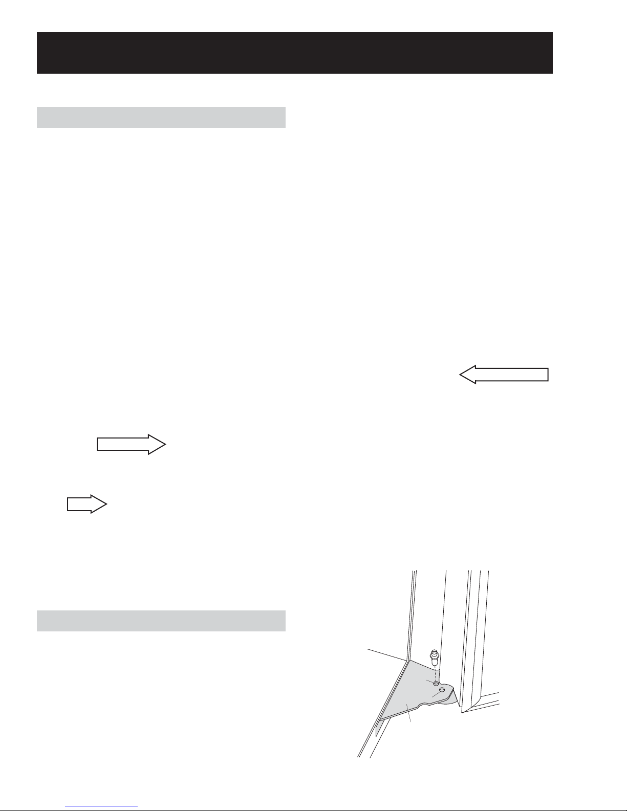
Door Water Line Replacement
To remove the existing water line, remove
the screws from the water line retainer at the
dispenser, then pull the retainer off the tubing.
From the bottom of the door, disconnect the water
line and pull it down and out.
To install the new water line, soak the new line in
hot water (to make it pliable) and insert it into the
door at the dispenser location. Feed the water
line into the door, until it emerges through the
bottom hinge as shown in the photo below. (The
stainless steel panel is shown pulled away from
the door for clarity).
Caution: Do NOT connect or disconnect CN1
connector with power applied. Always turn off
power at the main switch to avoid arcing at
connector terminals.
CN01
Note: On custom panel models, it may be
necessary to remove the door handle and slide
the panel to the right to feed the water line past
the bend.
Note: If the refrigerator is dead (no lights or
component operation), check for power to CN1.
Ensure the main switch is operating correctly.
Check for loose connectors at the terminal block.
– 34 –
Page 35

8
To check power to the main switch, check for
120 VAC between the black and red wires on the
connector shown below.
Compressor Circuit
3
COMP
2
1
BLACK
PURPLE
BLUE
CN0
7
8
Power to
Main Switch
Power Return
from Main
Switch
Compressor
The refrigerator contains a variable speed inverter
compressor (2200 to 3800 RPM). The inverter is
part of the main power control board (PCB). The
compressor will start (if required) one minute after
power is applied to the refrigerator. Compressor
operation is determined by the fresh food and
freezer thermistors.
LIGHT BLUE
LIGHT BLUE
OVER-LOAD PROTECTOR
14
15
16
Refrigerant Charge
The refrigerant used in the sealed system is
R134a. Proper system charge is 8.11 oz.
Heat Exchanger
The heat exchanger is located at the rear of the
machine compartment, behind the compressor.
The tubing is coiled and foamed into a galvanized
cover. A replacement heat exchanger and cover
come as a complete assembly.
Should the compressor fail to start when required,
check the compressor windings and associated
wiring harness BEFORE checking for a power
control board (PCB) problem. The compressor
resistance between each pin should be
approximately 12 Ω. Measure the resistance at
CN08, between pin #7 (black wire), pin #8 (purple
wire), and pin #16 (blue wire).
A thermal overload, designed to protect the
compressor, is mounted within the compressor
terminal cover. The overload will open at 257°F
(125°C) and close at 156°F (69°C). The overload
should be checked at CN08, between the pin #14
and pin #15 (light blue wires).
Note: An open compressor overload will prevent
the main control board from operating. If voltage
is present at CN01, and the refrigerator is dead
(except for the interior lights), check to make
certain the thermal overload is closed.
Heat Exchanger Cover
Shown with Cover Cut Open
– 35 –
Page 36

Muffl ers
3-Way Valve
The sealed system has 2 muffl ers to reduce
noise, one in the suction line and one in the
compressor discharge line.
Muffl er
Suction Line
Discharge Line
Muffl ers Cross-Cut View
The 3-way valve directs the refrigerant fl ow to
the two evaporators as needed, and is controlled
by the power control board (PCB). It is located
on the right side of the condenser, behind the
condenser's front plate.
3-Way Valve
Muffl er
The 3-way valve is held in place by 2 Phillipshead screws.
Drier
The drier is positioned vertically in the center of
the machine compartment. A short jumper tube
runs from the drier to the 3-way valve behind it.
The standard replacement drier is WR86X93.
Use the fi lter drier WR86X96 if the system has
been contaminated.
Note: When the compressor fi rst cycles off, the
drier surface may have moisture beads and
feel cold to the touch. This is normal due to the
refrigerant equalizing through the evaporators.
Drier
Screws
The valve is composed of a magnetic coil and
valve body.
Coil
Valve body
– 36 –
Page 37

Testing
Replacement
To test whether the 3-way valve is receiving a
signal from the power control board:
1. Turn the power OFF at the main switch for at
least 10 seconds.
2. Place a fi nger on top of the valve.
Caution: Be careful of the condenser fan and any
exposed wires.
3. Turn the main switch back on. You should feel
movement, and you may hear the 3-way valve
move to the home position.
4. If movement is detected, the power control
board and valve coil should be OK.
When replacing the 3-way valve, note the red
sleeve on the valve tube. This tube connects to
the freezer capillary. The corresponding freezer
capillary has red paint above the braze joint.
To Freezer Capillary
Check for proper resistance of the valve coil
windings at the coil harness.
Orange - Gray = 40 Ω
Blue - Gray = 40 Ω
Orange - Blue = 80 Ω
Gray - Black = 40 Ω
Gray - Yellow = 40 Ω
Yellow - Black = 80 Ω
CN02
RED
4
BLACK
5
STEP MOTOR
GRAY
8
9
10
BLUE
YELLOW
ORANGE
1
BLACK
2
YELLOW
5
ORANGE
3
BLUE
4
1
2
5
3
4
The 3-way valve is extremely sensitive to heat.
When brazing, thoroughly cover the valve base
with heat absorbing paste (part # WR5X8927).
Make certain to direct the fl ame away from the
valve body.
Heat Absorbing Paste
– 37 –
Page 38

Door Switches
The refrigerator is equipped with an AC and a DC
switch above each door. The switches are located
inside the machine compartment.
Freezer Door
The DC switches provide “door open” information
to the power control board (PCB).
Note: The fans turn off when the doors are
opened (DC door switches control operation)
and delay 10 seconds before restarting when the
doors are closed again. The freezer door switch
controls only the freezer fan. The fresh food door
switch controls both the fresh food and freezer
fan operation.
DC DOOR SWITCHES
AC Switch
Fresh Food Door
DC Switch
DC Switch
AC Switch
The AC switch, above the freezer door, controls
the freezer interior lights and the auger motor
operation. The freezer light is switched through
the neutral side of the line.
The AC switch, above the fresh food door,
controls the fresh food interior lights.
AC DOOR SWITCHES
NEUTRAL
CN08
RED
FRESH FOOD
DOOR SWITCH
FREEZER DOOR SWITCH
PURPLE/BLUE
YELLOW
ORANGE
BLACK
AUGER MOTOR
10
FRESH FOOD LIGHT
11
FREEZER LIGHT
12
LINE (L1)
13
CN02
6
7
13
WHITE/YELLOW
GRAY
WHITE/BLUE
FREEZER DOOR
SWITCH
FRESH FOOD
DOOR SWITCH
Interior Lights
Both the fresh food and freezer interior lights use
120 VAC, 40-watt incandescent bulbs. There are
4 bulbs (160 watts) in the fresh food section, and
2 bulbs (80 watts) in the freezer section.
Freezer bulb voltage is checked at CN07 on the
terminal block. Test for voltage between pin #9
and pin #10.
Note: Pin #10 is only at neutral when the freezer
door AC switch has closed contacts (door open).
Fresh food bulb voltage is checked at CN09 on
the terminal block. Test for voltage between pin
#4 (neutral) and pin #3.
Note: Pin #3 is only at line voltage (120 VAC)
when the fresh food AC door switch has closed
contacts (door open).
WARNING: The center terminal of the freezer
light socket is energized whenever the refrigerator
is plugged in and the main switch is closed,
regardless of door position.
– 38 –
Page 39

Thermistors
The main control board uses input from 5
thermistors:
• Ambient
• Freezer
• Fresh Food
• Freezer Evaporator
• Fresh Food Evaporator
The thermistors have a negative coeffi cient.
As the temperature increases, the thermistor’s
resistance decreases.
Testing
The most accurate
method of testing a
thermistor is to place it
in a glass of ice water
for several minutes. The
thermistor should read
approximately 13K Ω
in the glass of 33°F ice
water.
Note: Thermistors can also be checked for an
open or shorted condition by using the diagnostic
mode (see
Ambient Thermistor
The ambient thermistor measures room
temperature and is clipped to the back of the
dispenser cover. Check for thermistor resistance
Thermistor Chart) by disconnecting the
(see
harness at CN03 and testing between pin #4
(gray wire) and pin #6 (red wire) on the harness.
Freezer Air Thermistor
The freezer air thermistor is clipped to the inside
of the evaporator cover.
Check for thermistor resistance (see
Chart
testing between pin #3 (gray wire) and pin #5
(brown wire) on the harness.
Fresh Food Air Thermistor
The fresh food air thermistor is clipped to
the inside of the ceiling cover. Check for
thermistor resistance (see
disconnecting the harness at CN05 and testing
between pin #2 (gray wire) and pin #3 (yellow
wire) on the harness.
Service Diagnostics).
Thermistor
) by disconnecting the harness at CN06 and
Thermistor Chart) by
Freezer Evaporator Thermistor
The evaporator thermistor is mounted in a copper
sleeve on the top, right corner of the evaporator.
Check for thermistor resistance (see
) by disconnecting the harness from CN06
Chart
Thermistor
and testing between the pin #3 (gray wire) and
pin #6 (red wire) on the harness.
Fresh Food Evaporator Thermistor
The fresh food evaporator thermistor is mounted
in a sleeve on the left side of the evaporator.
Check for thermistor resistance (see
Chart) by disconnecting the harness at CN05 and
Thermistor
testing between pin #2 (gray wire) and pin #4
(pink wire) on the harness.
Thermistor Chart
°F
-9 37K -23
-6 34K -21
0 29K -18
6 25K -14
32 13K 0
37 12K 3
50 8.8K 10
77 5K 25
86 4.2K 30
95 3.5K 35
Resistance In
Ohms (KΩ)
°C
Thermistor Emergency Operation
If the freezer thermistor opens (or shorts), the unit
defaults to the freezer evaporator thermistor. The
compressor and freezer fan cycle off when the
freezer evaporator temperature is -22°F (-30°C)
or colder. The compressor and freezer fan cycle
on when the freezer evaporator temperature is
-2°F (-19°C) or warmer.
If the fresh food thermistor opens (or shorts),
the fresh food cooling operation defaults to the
freezer thermistor. Refrigerant will fl ow through
the fresh food evaporator any time the freezer
evaporator is cooling. The fresh food fan will cycle
off once the fresh food evaporator thermistor
reaches 5°F (-15°C) or colder.
– 39 –
Page 40

Defrost Cycles
The refrigerator incorporates two different
methods of defrost. Once the compressor has
accumulated 2 hours of compressor run time, and
certain conditions are satisfi ed, the fresh food
evaporator goes through a "natural defrost" cycle.
In addition, at a specifi c time interval, both the
fresh food and freezer evaporators go through a
"heated defrost" cycle.
Natural Defrost (Fresh Food Only)
Once the fresh food temperature is satisfi ed,
natural defrost occurs on the fresh food
evaporator, if the following conditions have been
met:
• The compressor has accumulated 2 hours of
run time.
• The ambient room temperature is above 66°F
(19°C).
• The freezer temperature is satisfi ed.
If the above conditions have been met, when
the fresh food temperature is satisfi ed, and the
compressor cycles off, the 3-way valve will open
to both the fresh food and freezer evaporators.
This allows the refrigerant within the system to
equalize back through the evaporators. This
warm thermal mass (refrigerant) fl owing through
the evaporators helps to remove any frost
buildup on the fresh food evaporator (it has very
little impact on the freezer evaporator due to
the freezer temperature). In addition, when the
fresh food evaporator thermistor is below 23°F
(-5°C), the fresh food evaporator fan will run to
help move air across the evaporator. Once the
thermistor reaches 28°F (-2°C), the fan will cycle
off.
Note: If the compressor is still cooling the freezer
section when the fresh food cycles off, or the
ambient room temperature is below 66°F (19°C),
natural defrost will not occur.
Heated Defrost
In normal cooling operation (normal food load,
door openings, etc.), the power control board
(PCB) will energize the fresh food defrost heater
every 5 hours of compressor running time and
the freezer defrost heater every 10 hours of
compressor running time.
For example, after approximately 10 accumulated
hours of compressor running time, the freezer
evaporator will have gone through one defrost
cycle, and the fresh food evaporator will have
gone through two defrost cycles.
The fresh food heater cycles off when the fresh
food evaporator thermistor reaches 63°F (17°C).
The freezer heater cycles off when the freezer
evaporator thermistor reaches 68°F (20°C). The
compressor and fans do not operate when either
section is defrosting, regardless of the cabinet
temperature. There is a 10-minute dwell period
after the heater cycles off.
Note: Upon initial power-up, the fresh food and
freezer go into heated defrost simultaneously,
after 4 hours of accumulated compressor run
time.
During unusual cooling situations where there are
no door openings (such as vacations), the time
between heated defrost cycles may increase.
If the ambient room temperature is above 82°F
(28°C) and there are no door openings, the fresh
food defrost occurs every 8 hours, and the freezer
defrost occurs every 16 hours. If the ambient
room temperature is below 82°F (28°C), defrost
occurs at the normal intervals – fresh food defrost
every 5 hours and freezer defrost every 10 hours
of accumulated compressor run time.
Thermistor Error Defrost Operation
If either evaporator thermistor fails (open or
shorted), the power control board (PCB) defaults
to a timed defrost cycle based on cabinet
temperature.
If the freezer evaporator thermistor fails (open
or shorted) and the freezer temperature is
below 27°F (-3°C), the freezer defrost heater
will be energized for 20 minutes. If the freezer
temperature is above 27°F (-3°C), the heater will
not come on.
If the fresh food evaporator thermistor fails (open
or shorted) and the fresh food temperature is
below 68°F (20°C), the fresh food defrost heater
will be energized for 10 minutes. If the fresh food
temperature is above 68°F (20°C), the heater will
not come on.
During thermistor error operation, the control
defaults to fresh food defrost every 5 hours and
freezer defrost every 10 hours of accumulated
compressor run time.
– 40 –
Page 41

Fans
All 3 fans (condenser, freezer, and fresh food) are
variable-speed DC fans. The speed of each fan
is controlled by an algorithm in the power control
board (PCB) and determined by many factors,
such as room ambient, thermal load, temperature
settings, number of door openings, etc. The fans
are extremely QUIET, and determining fan speed
is very diffi cult. As a general rule, if the voltage
measured at the fan is within limits and airfl ow
is felt through the vents, assume the fans are
working correctly.
Note: The fans will run on a 9-volt battery for
testing purposes. Use the two higher voltage pins
as described in the following procedures.
Freezer Evaporator Fan
The freezer fan assembly is mounted directly to
the freezer evaporator. The fan assembly (motor,
blower and housing) is available as a separate
part or complete and preassembled on a new
freezer evaporator.
Operation of the freezer fan is also affected by
room temperature. If the ambient thermistor
senses a temperature of 82°F (28°C) or higher,
the freezer fan will delay 5 minutes (after the
compressor has started) before starting and
circulating the freezer air. Below 82°F (28°C), the
fan will start immediately with the compressor.
The freezer evaporator fan motor supply voltage
can be checked at CN06 on the terminal block.
The fresh food evaporator fan motor supply
voltage can be checked at CN05 on the terminal
block. When the power control board (PCB)
is energizing the fan, check for approximately
7 to 8 VDC between pin #2 and pin #6, and
approximately 2 VDC between pin #2 and pin #5
at CN05.
CN05
GRAY
2
5
6
BROWN
ORANGE
LIGHT BLUE
3
ORANGE
4
GRAY
5
2
4
1
WHITE
RED
BLACK
BLDC R-FAN
Condenser Fan Assembly
Ambient temperature affects the operation of the
condenser fan. If the room temperature is less
than 45°F (7°C), the condenser fan will not run
when the compressor is on. If the temperature
is between 45°F (7°C) and 50°F (10°C), the fan
will start 5 minutes after the compressor has
started. Above 50°F (10°C) (or if the ambient
thermistor is open or shorted), the condenser fan
is synchronized with the compressor.
Condenser Fan Assembly
When the power control board (PCB) is
energizing the fan, check for approximately 8 to11
VDC at CN06, between pin #2 and pin #3, and
approximately 2.25 VDC, between pin #1 and pin
#3 .
CN06
1
2
3
BLACK
YELLOW
GRAY
LIGHT BLUE
ORANGE
GRAY
Fresh Food Evaporator Fan
The fresh food fan assembly is mounted directly
to the fresh food evaporator. The fan assembly
(motor, blower, and housing) is available as a
separate part or complete and preassembled on
a new fresh food evaporator.
WHITE
RED
BLACK
BLDC F-FAN
The condenser fan assembly is held in place
by 2 Phillips-head screws at the front and 2
tabs at the rear. The 2 tabs are inserted into
the rear condenser mounting plate. The 2 front
screws attach the shroud assembly to the front
condenser plate. (See photo below.)
Shown with Condenser Fan Assembly Removed
Tab Location
Tab Location
– 41 –
(Continued Next Page)
Page 42

The 3-bladed fan can be removed without
removing the complete fan assembly.
The fan rotates counterclockwise as viewed from
the motor shaft end. It is held in place by a spring
retention clip.
To remove the condenser fan assembly:
1. Remove the water fi lter cartridge.
2. Remove the 2 Phillips-head screws from the
water fi lter receptacle.
6. Pull the cabinet wiring down as shown in the
photo below. Carefully pull the condenser fan
assembly out of the machine compartment.
Fan Assembly
Cabinet Wiring
Installing the condenser fan assembly:
1. Secure the wires to the condenser fan shroud
to prevent interference with the fan blade
rotation.
2. Ensure the rubber tab covers are in place
when reinstalling the condenser fan assembly.
3. Remove the 2 Phillips-head screws from the
front of the shroud assembly and disconnect
the fan wiring.
4. Bend the 2 wire retention tabs back to release
the wire harness.
5. Pull the fan forward and tilt it to the left to
release the 2 water fi lter tubes from the
channel at the top of the condenser fan motor
shroud.
Top Vie w
Ta b
Ta b
3. Ensure water fi lter lines are fully seated into
the top channel of the water fi lter housing
bracket.
Voltage Checks
When the power control board (PCB) is
energizing the fan, check for approximately 9
to10 VDC between pin #2 and pin #3 at CN02
on the terminal block. Check for approximately
2 VDC between pin #1 and pin #3 at CN02.
CN02
– 42 –
1
2
3
RED
LIGHT BLUE
GRAY
R4
L1
R2
BROWN
PURPLE
GRAY
2
4
1
BLDC C-FAN
Page 43

Fresh Food Heater Testing
Freezer Heater Testing
The fresh food evaporator defrost heater,
evaporator drain pan heater, and icemaker fi ll
tube heater are in a parallel circuit. The heaters
are in series with the bimetal defrost safety
thermostat.
Check for a combined resistance of 91 Ω at CN09
on the terminal block, between pin #1 and pin #2,
when the defrost safety thermostat is closed.
When the fresh food is in the defrost test mode
1 4 (see
Service Diagnostics) check for 120 VAC
at CN09 on the terminal block, between pin #1
and pin #2.
Note: Access to the evaporator is necessary to
complete testing of the above components, with
exception of the icemaker fi ll tube heater.
WHITE
RED
CN09
1
2
BIMETAL
THERMOSTAT
FF DEFROST HEATER 120
FF DRAIN HEATER 440
FILL TUBE HEATER 2.6K
The freezer evaporator defrost heater, suction
line drain pan heater, and the evaporator drain
pan/drain tube heater are in a parallel circuit.
The heaters are in series with the bimetal defrost
safety thermostat.
Check for a combined resistance of
approximately 38 Ω at CN07, on the terminal
block, between pin #1 and pin #2.
When the freezer is in defrost test mode 1 4 (see
Service Diagnostics), check for supply voltage of
120 VAC at CN07 on the terminal block, between
pin #1 and pin #2.
Note: Access to the evaporator is necessary to
complete testing of the above components, with
the exception of the suction line drain pan heater.
BIMETAL
THERMOSTAT
DEFROST HEATER 44
SUB HEATER 377
DRAIN HEATER 1.3K
BROWN
ORANGE
CN7
1
2
• The resistance value of the defrost heater is
approximately 120 Ω.
• The resistance value of the drain pan heater
is approximately 440 Ω.
• The resistance value of the icemaker fi ll tube
heater (referred to as the “PIPE HEATER
ICE WATER” on some schematics) is
approximately 2.6K Ω.
• The defrost safety thermostat is a bimetal
type which will open at 140°F (60°C) and will
reset at 104°F (40°C).
• The resistance value of the defrost heater is
approximately 44 Ω.
• The resistance of the suction line drain pan
heater (referred to as the "
DRAIN HEATER" on
some schematics) is approximately 1.3K Ω.
• The resistance value of the evaporator drain
pan and drain tube heater (referred to as
the "SUB HEATER" on some schematics) is
approximately 377 Ω.
• The defrost safety thermostat is a bimetal
type which will open at 140°F (60°C) and will
reset at 104°F (40°C).
– 43 –
Page 44

Freezer Evaporator Assembly
6. Remove the rear air duct cover.
The freezer evaporator assembly consists of an
evaporator, defrost and drain heaters, defrost
safety thermostat, thermistor, and fan assembly.
All the parts are available as a complete
replacement assembly, or the components are
available individually.
All components are housed together and installed
in a recessed compartment in the freezer ceiling.
To access the freezer evaporator assembly:
1. Remove the ice container shelf, then remove
the icemaker.
2. Remove 4 Phillips-head screws that hold the
top air duct cover in place.
Air Duct Cover
7. Remove the 2 Phillips-head screws from the
suction line drain pan and heater assembly.
Disconnect the associated wiring.
Note: The suction line drain pan heater has a
resistance value of 1.3K Ω.
Drain Pan
3. Remove auger motor and cube motor
connectors from the freezer evaporator cover.
4. Remove the 2 Phillips-head screws that hold
the rear air duct cover in place, then pull it
down.
5. Disconnect all the electrical connectors from
the ceiling.
Connectors
Rear Air Duct Cover
8. Carefully remove the styrofoam air duct.
Note: The styrofoam air duct is held in place by
adhesive.
Styrofoam Air Duct
– 44 –
Page 45

9. Remove the 2 Phillips-head screws that hold
the freezer plug cover in place, then remove
the freezer plug cover.
Freezer Plug Cover
11. Remove the 2 Phillips-head screws that hold
the freezer evaporator assembly housing in
place.
Assembly Housing
12. Lower the evaporator assembly into the
freezer compartment.
10. Disconnect the freezer evaporator wiring.
Note: When installing plug cover, place wiring
connectors inside the cover, then mount the plug
cover to the wall.
13. Place the freezer shelf in the top position.
Place the evaporator assembly on the shelf.
Caution: Refrigerant lines may be damaged if the
evaporator assembly is left unsupported.
– 45 –
Page 46

Freezer Evaporator Fan Assembly
The freezer evaporator fan assembly consists
of a 2-speed DC fan motor, blower wheel, and
housing. It is mounted on top of the evaporator.
To remove the freezer evaporator fan
assembly:
1. Access the freezer evaporator assembly. (See
Freezer Evaporator Assembly.)
2. To access the fan assembly screws, support
the evaporator assembly from the machine
compartment grille mounting bracket with a
bent wire hook (see photo).
Note: When installing the fan assembly, ensure
that the housing lip inserts into the channel.
Channel
Housing Lip
Freezer Evaporator
Bracket
Wire
Evaporator Assembly
3. Remove the 4 Phillips-head screws that
hold the evaporator fan assembly in place.
Remove the evaporator fan assembly.
To access the freezer evaporator:
1. Access the freezer evaporator assembly. (See
Freezer Evaporator Assembly.)
2. Remove the freezer evaporator fan assembly.
(See Freezer Evaporator Fan Assembly.)
3. Place the freezer shelf in the top position.
Place the evaporator assembly on the
shelf. (Note the position of all wiring prior to
disassembly.
4. Starting at one corner, use a screwdriver and
unlock the 6 tabs from the housing cover.
Housing Cover
1 of 4 Screws
– 46 –
Page 47

WARNING: The evaporator fi ns are very sharp.
Wear Kevlar gloves when handling.
5. Remove the single Phillips-head screw at the
corner of the evaporator.
6. To access the remaining Phillips-head
screw that holds the evaporator in place,
suspend the evaporator from the machine
compartment grille mounting bracket with a
bent wire hook. Remove the screw.
Freezer Evaporator Components
To access the freezer evaporator components:
1. Access the freezer evaporator assembly. (See
Freezer Evaporator Assembly.)
2. Remove the freezer evaporator fan assembly.
Freezer Evaporator Fan Assembly.)
(See
3. Access the freezer evaporator. (See
Evaporator.)
Defrost Safety Thermostat
To remove the defrost safety thermostat, remove
the single Phillips-head screw from the thermostat
mounting bracket. Separate the thermostat from
the bracket.
Defrost Safety Thermostat
Freezer
Note: The screw may be covered by foil.
7. Lift the evaporator from the housing.
Freezer Evaporator Thermistor
To remove the freezer evaporator thermistor, pull
it straight out from its mounting tube.
Thermistor
Defrost Heater
To remove the defrost heater, remove the 2
Phillips-head screws from the evaporator defrost
heater mounting brackets. Separate the defrost
heater from the evaporator.
Heater
Screw
Bracket
– 47 –
Page 48

Fresh Food Evaporator Assembly
The fresh food evaporator assembly consists
of an evaporator, defrost and drain heaters,
bimetal defrost safety thermostat, thermistor, and
evaporator fan assembly.
All components are housed together and
installed in the refrigerator interior in a recessed
compartmet in the refrigerator ceiling. This
compartment extends vertically into the machine
compartment.
To access the fresh food evaporator
assembly:
1. Remove the fresh food grille cover by
inserting a fl at-blade screwdriver into the slot
(see photo) and lifting up.
4. Remove the 4 Phillips-head screws that hold
the refrigerator suction line drain assembly in
place. Remove the assembly.
5. Remove the 2 Phillips-head screws that hold
the fresh food upper duct cover assembly in
place. Remove the upper duct cover.
2. Remove 4 Phillips-head screws from the
fresh food air duct cover. Pull the front of the
cover down.
3. Disconnect the thermistor and lighting
connector. Remove the fresh food air duct
cover.
Thermistor Connector
Lighting Connector
Air Duct Cover
6. Disconnect the remaining electrical
connectors.
7. Remove 2 Phillips-head screws from the fresh
food evaporator housing.
– 48 –
Page 49

8. Lower the evaporator assembly into the fresh
food compartment.
9. Place the fresh food shelf in the top position.
Place the evaporator assembly on the shelf.
Fresh Food Evaporator Fan Assembly
To remove the fresh food evaporator fan
assembly:
1. Access the fresh food evaporator assembly.
Fresh Food Evaporator Assembly).
(See
2. The fan assembly is attached to the
evaporator assembly with 4 Phillips-head
screws (2 on each side of the fan assembly).
Remove the 4 screws that hold the fan
assembly in place.
Fan Assembly
Caution: Refrigerant lines may be damaged if the
evaporator assembly is left unsupported.
3. Separate the fan assembly from the
evaporator assembly.
– 49 –
Page 50

Fresh Food Evaporator
To access the fresh food evaporator:
1. Access the fresh food evaporator assembly.
(See Fresh Food Evaporator Assembly.)
2. Remove the fresh food evaporator fan
assembly. (See
Assembly.)
Fresh Food Evaporator Fan
3. Remove the tape from the front of the
Styrofoam cover. Note the position of the
wires under the tape. The tape must be
replaced after repair.
Fresh Food Evaporator Components
To access the fresh food evaporator
components:
1. Access the fresh food evaporator assembly.
Fresh Food Evaporator Assembly.)
(See
2. Remove the fresh food evaporator fan
assembly. (See
Assembly.)
3. Access the fresh food evaporator. (See
Food Evaporator.)
Defrost Safety Thermostat
Fresh Food Evaporator Fan
Fresh
4. Remove the Styrofoam cover.
WARNING: The evaporator fi ns are very sharp.
Wear Kevlar gloves when handling.
5. Remove the 2 Phillips-head screws that hold
the fresh food evaporator in place (Fig. 1 and
Fig. 2).
Fig. 1
Fig. 2
To remove the defrost safety thermostat,
remove the single Phillips-head screw from
the thermostat mounting bracket. Separate the
defrost thermostat from the bracket.
Defrost Safety Thermostat
Fresh Food Evaporator Thermistor
To remove the fresh food evaporator thermistor,
pull it straight out from its mounting tube.
Fresh Food Thermistor
6. Disconnect the 2 electrical connectors and lift
the fresh food evaporator from the housing.
WARNING: The evaporator fi ns are very sharp.
Wear Kevlar gloves when handling.
Note: The defrost heater is not available
separately and only comes as a part of the
evaporator assembly.
– 50 –
Page 51

Replacing the Freezer or Fresh Food
Evaporator
The freezer evaporator can be replaced as a
complete unit, including the defrost components
and fan assembly, or it can be replaced as an
individual component.
The fresh food evaporator can be replaced as
a complete unit or as an assembly consisting of
the evaporator and defrost heater (the fresh food
defrost heater is not available separately).
To replace the freezer or fresh food
evaporator:
1. Access the specifi c evaporator as described
Fresh Food Evaporator Assembly or Freezer
in
Evaporator Assembly.
6. Carefully cut and remove the insulation on the
suction line and capillary tubing to expose the
solder joints.
Capillary Tubing
Suction Line
2. In the machine compartment, remove the
screws that hold the main switch in place.
Move the main switch out of the way to
provide better access to the evaporator
tubing.
Evaporator Tubing
Main Switch
3. Remove the condenser fan assembly from the
compartment. (See
Fans.)
4. Remove the 5 Phillips-head screws holding
the metal cover over the Styrofoam block (see
photo below). Remove the metal cover.
5. Remove the Styrofoam block from the base of
the evaporator tubing.
Note: Save the insulation to rewrap the
refrigerant tubing after brazing.
7. Recover the refrigerant. (See
Charging Procedures).
Evacuation and
8. Disconnect the suction line and capillary of
the specifi c evaporator to be replaced. Note
the position of the tubing within the machine
compartment. Pull the evaporator tubing down
from the cabinet and remove the evaporator.
9. Install the new evaporator and carefully bend
the tubing to the correct position. Braze the
suction line and capillary tubing.
10. Replace the drier (part # WR86X93) and
install a process valve (part # WJ56X61) at
the compressor.
11. Reinstall the remaining components within
the cabinet section while the braze joints are
cooling.
12. Charge the system with the exact amount of
refrigerant (8.11 oz.) specifi ed on the rating
plate
13. Check for refrigerant leaks at all joints.
Metal Cover
Note: Adhesive may be holding the Styrofoam
block in place after the metal cover is removed.
Styrofoam Block
14. Reinstall insulation around the tubing. Wrap
with tape to provide a good airtight seal.
15. Reinstall Styrofoam block and metal cover.
16. Check refrigerator for proper operation.
– 51 –
Page 52

Service Diagnostics
Diagnostic Mode
1. To enter the diagnostic mode, the temperature
display must be lit up. If the temperature
display is not lit, press any pad on the overlay.
ADJUST TEMPERATURE
DISPLAY
TEMP
COLDER WARMER
REFRIGERATOR
COLDER WARMER
FREEZER
37º F IS RECOMMENDED
0º
F IS RECOMMENDED
ICE DISPENSER
QUICK ICECUBEDCRUSHEDWATE RDOOR ALARM
HOLD FOR
3 SECS
TO A CTI VATE
LOCK
LIGHT
RESET FILTER
HOLD 3 SECS
2. Press the 2 COLDER and 2 WARMER pads
simultaneously for three seconds. The FREEZER
and REFRIGERATOR displays will change to 0 0.
Press Simultaneously
ADJUST TEMPERATURE
COLDER WARMER
REFRIGERATOR
COLDER WARMER
FREEZER
37º F IS RECOMMENDED
0º
F IS RECOMMENDED
4. Once the displays indicate a test mode, press
any pad on the temperature board overlay,
other than the
COLDER or WARMER pads, to enter
that mode.
Note: A test mode must be selected within 30
seconds of entering the diagnostic mode or it
will time out, normal refrigerator operation will
resume, and the displays will turn off. Once a test
mode is selected, the display will fl ash to confi rm
the mode selected.
5. At the end of a test session, to exit the
diagnostic mode, do one of the following:
• Enter 1 on the
FREEZER display and 5 on
the REFRIGERATOR display. Press any pad
other than the COLDER or WARMER pads to
execute a system restart.
• Enter 1 on the FREEZER display and 6 on
the REFRIGERATOR display. Press any pad
other than the COLDER or WARMER pads to
exit the service diagnostic test mode.
• Recycle power to the unit through the
main switch. As a cautionary measure,
the system will automatically time out of
the diagnostic mode after 15 minutes of
inactivity. In the diagnostics mode, the unit
can be tested under different conditions.
3. To select a test mode:
a. Enter a numeric value (see Test Mode
Chart) on the FREEZER display using the
COLDER or WARMER pad.
Note: The COLDER pad decreases the numeric
value. The WARMER pad increases the numeric
value.
b. Enter a numeric value (see
Chart) on the REFRIGERATOR display using
the COLDER or WARMER pad.
Test Mode
– 52 –
Page 53

Test Mode Chart
FZ Display FF Display Mode Comments
0 1 Showroom Mode See Note #1.
0 2 Do Not Use
0 3 Do Not Use
0 4 Do Not Use
0 5 Do Not Use
0 6 HMI Self-Test See Note #2.
0 7 Control and Sensor Self-Test See Note #3.
0 8 Do Not Use
0 9 Dispenser Recess Heater Test Turn the dispenser heater ON for 30 seconds.
1 0 Do Not Use
1 1 Fan Speed Test Each fan will run for 5 seconds.
1 2 100% RunTime See Note #4.
1 3 Do Not Use
1 4 Toggle the State of Defrost See Note #5.
1 5 Refrigerator Reset Causes a system reset except for defrost.
1 6 Test Mode Exit Exit test mode.
1 7 Do Not Use
1 8 Do Not Use
Note #1 (Showroom Mode)
In the showroom mode, the compressor and fans do not operate. The fresh food and freezer lights
operate as normal (ON when door is opened). The dispenser and dispenser display operate as normal.
Temperature set points can be changed. Press the
DISPLAY TEMP pad to display the actual cabinet
temperature. To exit the showroom mode, cycle power OFF or enter test mode 1 5 to reset the unit.
Note: The showroom mode can also be entered outside of the service mode by simultaneously
pressing the
COLDER pad on the FREEZER display and the WARMER pad on the REFRIGERATOR display for 3
seconds (the display must be lit before pressing the pads).
Press Simultaneously
ADJUST TEMPERATURE
COLDER WARMER
REFRIGERATOR
COLDER WARMER
FREEZER
Note #2 (HMI Self-Test)
Once the HMI self-test is started, all of the LEDs and seven segment LEDs will illuminate. The COLDER
pad turns off the seven segment LEDs and the WARMER pad turns off the SET LED for both the FREEZER
and REFRIGERATOR displays.
37º F IS RECOMMENDED
0º
F IS RECOMMENDED
When all the available LEDs have been turned off for that specifi c temperature board, the
WARMER pads on the REFRIGERATOR display must be held simultaneously for 3 seconds to exit the HMI
self-test. This can be done any time during the test.
COLDER and
(Continued next page)
– 53 –
Page 54

Note #3 (Control and Sensor System Self-Test)
This test does a check on all thermistors, fans, and defrost circuits. The thermistor test will display
pass, open or shorted. The fan and defrost tests will display pass or fail. Once this test is invoked,
the test mode will stop fl ashing and the numbers from 1 to 10 (corresponding to the chart below) will
appear on the HMI display.
1
2
3
4
5
FZ Room Sensor
FZ Defrost Sensor
FF Room Sensor
FF Defrost Sensor
Ambient Sensor
6
7
8
9
10
FZ Fan Error
FF Fan Error
Condenser Fan Error
FZ Defrost Error
FF Defrost Error
For each test, the HMI will respond by displaying the following:
P = Pass
F = Fail
O = Open Thermistor Circuit
S = Short Thermistor Circuit
The control will display an O if the thermistor value is greater than 149.2K Ω (-58°F (-50°C)). The
control will display a S if the thermistor value is less than 1.34K Ω (149°F (65°C)).
Note #4 (100% Run Time)
This test runs the sealed system 100% of the time and will automatically time out after 1 hour. Cycle
power OFF or enter test mode 1 5 to reset and exit this mode.
Note: The 3-way valve position during 100% run time depends on the fresh food temperature. If the
fresh food temperature is satisfi ed, the 3-way valve opens to the freezer evaporator only. If it is not
satisfi ed, the valve opens to the fresh food evaporator and refrigerant fl ows through both evaporators.
Note #5 (Toggle the State of Defrost)
Any time a pad on the temperature board (other than the
COLDER and WARMER pads) is pressed, the
status of the defrost heaters will toggle in the following sequence:
Fresh food heater ON.
1.
Fresh food and freezer heaters ON.
2.
Fresh food and freezer heaters OFF.
3.
Pressing the pad a fourth time will cycle through the sequence again. During the sequence, heater
current can be measured.
• Fresh food heater - approximately 1.2 amps when measured at the CN01 connector black wire.
• Fresh food and freezer heaters - approximately 4 amps when measured at the CN01 connector
black wire.
– 54 –
Page 55

Troubleshooting Notes
Problem Action
Refrigerator HMI displays a temperature of 80°F
(27°C), even though the temperature in the
refrigerator section is correct.
The HMI may display 80°F (27°C) if the
refrigerator thermistor (air) is either open or
shorted. Run service diagnostics (Test 0 7) to
confi rm.
Freezer HMI displays -25°F (-32°C), even though
the temperature in the freezer section is correct.
Freezer HMI displays 80°F (27°C), even though
the temperature in the freezer section is correct.
Unit is dead (except for interior lights). CN1
connector reads 120VAC.
Ambient air thermistor fails service diagnostics
test. HMI displays open circuit.
The HMI may display -25°F (-32°C) if the freezer
thermistor (air) is open. Run service diagnostics
(Test 0 7) to confi rm.
The HMI may display 80°F (27°C) if the freezer
thermistor (air) is shorted. Run service diagnostics
(Test 0 7) to confi rm.
Check the compressor overload. Control board
will not receive voltage if the overload is open.
Check the thermistor connection behind the HMI
display to see if the pins are pushed out of the
connector.
– 55 –
Page 56

Schematics
PSB42LGRBV PSB42LGRWV PSB42LSRBV
PSB48LGRBV PSB48LGRWV PSB48LSRBV
AC Section
CHOKE
(Part 1)
– 56 –
Page 57

Schematics (Part 2)
DC Section
– 57 –
Page 58

PSB42LSRBV Shown
Illustrated Parts
– 58 –
Page 59

PSB42LSRBV Shown
– 59 –
Page 60

PSB42LSRBV Shown
– 60 –
Page 61

PSB42LSRBV Shown
– 61 –
Page 62

PSB42LSRBV Shown
– 62 –
Page 63

PSB42LSRBV Shown
– 63 –
Page 64

PSB42LSRBV Shown
– 64 –
Page 65

PSB42LSRBV Shown
– 65 –
Page 66

PSB42LSRBV Shown
– 66 –
Page 67

PSB42LSRBV Shown
– 67 –
Page 68

VIEW NUMBER CATALOG NUMBER DESCRIPTION QUANTITY
0001 31-46170 INSTALLATION INSTRUCTION 1
0001
31-51582 MINI MANUAL 1
0001 49-60296-1 USE & CARE MANUAL 1
0100 WR78X11086 DOOR ASM FZ SS 1
0101 WR02X11890 TUBE-WATER LINE A 1
0103 WR23X10396 SWITCH-MICRO 1
0104 WR02X11891 CAP-TUBE WATER LINE 1
0105 WR02X11892 CAP-CHUTE ICE 1
0106 WR02X11894 BRKT-SOCKET LAMP DISP 1
0107 WR02X11893 SOCKET LAMP DISP 1
0108 WR49X10106 DISP UPGRADE KIT BK 1
0109 WR17X11763 FUNNEL BK 1
0110 WR17X11746 DUCT DOOR ASM 1
0111 WR17X11764 MICROS/HRNS/SUPT ASM BK 1
0112 WR02X11930 SCREW-TAPPING 2
0113 WR02X10675 LAMP-INCANDESCENT 1
0115 WR02X11895 STRIKE SWITCH 2
0116 WR02X11896 DOOR STOP 1
0117 WR02X11897 ASM BRACKET HINGE LOW 1
0118 WR02X11898 SCREW-SPECIAL 12
0119 WR24X10162 GASKET DOOR ASM FZ 1
0120 WR13X10350 SHIM HINGE-UPP,R 1
0121 WR17X11768 CONTROL DISPENSER BK 1
0124 WR17X11772 TRIM DISPENSER 1
0125 WR02X11929 COVER LAMP-DISPENSER 1
0126 WR50X10062 SENSOR TEMP-EXT 1
0127 WR17X11770 GRILLE RECESS BK 1
0128 WR17X11771 TRAY-DISP BK 1
0129 WR13X10343 HINGE UPPER FZ 1
0132 WR12X10705 ASM HANDLE DOOR 2
0139 WR02X11902 QUICK CONNECTOR TUBING 1
0142 WR71X10599 DOOR MODULE FZ 3
0143 WR60X10180 MOTOR & CAM - DUCT DOOR 1
0144 WR02X11943 TRIM PAD CRADLE 1
0145 WR02X11945 PAD CRADLE 1
0146 WR01X10468 SCREW-TAPPING 74
0200 WR78X11087 DOOR ASM FF SS 1
0201 WR02X11899 BRACKET HINGE-UPPER FF 1
0202 WR13X10351 SHIM HINGE-UPP,L 1
0203 WR02X11900 STOPPER DOOR FF 1
0205 WR02X11901 BRACKET HINGE BOTTOM FF 1
0206 WR24X10163 GASKET DOOR ASM FF 1
0215 WR02X11903 THIMBLE HINGE UPPER 2
0216 WR13X10345 HINGE-UPP R 1
0218 WR22X10051 BIN/DOOR DAIRY ASM 1
0220 WR22X10050 COVER DOOR-DAIRY 1
0221 WR71X10600 GUARD ASM FF 3
0222 WR02X11904 SNUGGER 3
0223 WR71X10601 GUARD-GALLON 1
0224 WR02X11905 SNUGGER LG 1
0301 WR85X10064 COMPLETE EVAP ASM FZ 1
0302 WR85X10062 EVAP/DEFROST HTR FZ ASM 1
– 68 –
Page 69

VIEW NUMBER CATALOG NUMBER DESCRIPTION QUANTITY
0304 WR60X10176 MOTOR FAN ASM FZ 1
0305
WR17X11730 CASE EVAP FZ FRONT 1
0306 WR17X11731 EVAP CASE REAR FZR 1
0308 WR02X11871 SCREW-TAPPING 14
0309 WR50X10056 THERMISTOR - FZ EVAP 1
0310 WR50X10057 THERMOSTAT DEFROST FZ 1
0311 WR02X11872 BRACKET THERMOSTAT FZ 2
0312 WR51X10082 DRAIN/HEATER ASM FZ 1
0314 WR50X10058 THERMISTOR - FZ 1
0315 WR17X11732 COVER EVAP FZ 1
0316 WR02X11873 CLAMP HOSE 2
0317 WR02X11874 DRAIN CONNECTOR 2
0318 WR17X11733 COVER AIR DUCT ASM FZ 1
0319 WR02X11875 DUCT FOAM UPPER FZ 1
0320 WR02X11876 COVER DUCT FZ 1
0321 WR23X10393 HARNESS LAMP FZ 1
0322 WR02X10732 SOCKET LAMP 6
0323 WR17X11734 RACK SHELVING FZ 2
0324 WR02X11877 SHIELD LAMP FZ 1
0325 WR02X11878 CAP-SCREW 8
0326 WR02X11879 PLUG COVER FZ 1
0327 40A15 LAMP-INCANDESCENT 6
0328 WR50X10063 DEFROST HEATER FZ 1
0400 WR71X10596 SHELF WIRE ASM 4
0401 WR21X10099 ASM-BASKET WIRE UPPER 1
0404 WR21X10100 ASM-BASKET WIRE LOW 1
0407 WR17X11727 RAIL RH BASKET FZ 2
0410 WR17X11728 RAIL LH BASKET FZ 2
0500 WR30X10012 ICE MAKER ASM 1
0501 WR30X10056 ICE BUCKET ASM W/FRONT 1
0502 WR02X11865 SCREW-TAPPING 25
0503 WR17X11722 ICE BUCKET FRONT 1
0504 WR30X10057 ICE BUCKET ASM 1
0505 WR17X11723 ICE BUCKET DOOR 1
0507 WR60X10175 MOTOR AUGER 1
0508 WR02X11867 COVER LEVER ARM 1
0509 WR02X11868 COVER-MOTOR AUGER 1
0510 WR60X10178 MOTOR & SWITCH ASM CUBE 1
0511 WR02X11869 DRIVE FORK AUGER 1
0512 WR02X11870 SCREW-SPECIAL 4
0513 WR02X11957 J-NUT 1
0514 WR17X11724 RAIL LH AUGER 1
0515 WR17X11725 RAIL RH AUGER 1
0516 WR29X10065 FILL CUP IM 1
0519 WR02X11866 SCREW-TAPPING 96
0600 WR85X10065 COMPLETE EVAP ASM FF 1
0601 WR85X10063 EVAP/DEFROST HTR ASM FF 1
0602 WR60X10179 FAN MOTOR ASM FF 1
0603 WR17X11739 EVAP CASE ASM FF 1
0604 WR02X11884 COVER EVAP FRONT FF 1
0605 WR82X10099 INSULATION EVAP MTR FF 1
– 69 –
Page 70

VIEW NUMBER CATALOG NUMBER DESCRIPTION QUANTITY
0608 WR50X10059 THERMISTOR FF EVAP 1
0609
WR50X10060 THERMOSTAT DEFROST FF 1
0611 WR02X11885 DRAIN TROUGH ASM FF 1
0616 WR50X10061 THERMISTOR FF 1
0617 WR23X10394 HARNESS UPPER LIGHTS FF 1
0618 WR17X11741 COVER DUCT ASM FF 1
0619 WR23X10395 HARNESS LOWER LIGHTS FF 1
0621 WR17X11742 TRACK SHELVING FF 2
0622 WR02X11886 COVER-GRILLE FF 1
0623 WR02X11887 SHIELD LAMP UPPER FF 1
0624 WR02X11888 SHIELD LAMP LOWER FF 1
0626 WR17X11743 WATER TANK ASM 1
0627 WR17X11744 COVER DUCT UPPER FF ASM 1
0628 WR17X11808 HSNG UPPER LIGHT ASM FF 1
0700 WR71X10597 SHELF GLASS FF 3
0701 WR71X10598 SHELF GLASS FF LOWER 1
0702 WR32X10495 PAN VEG UPPER 1
0707 WR32X10496 PAN VEG MID 1
0712 WR32X10497 COVER VEG PAN LOWER 1
0713 WR32X10498 PAN VEG LOWER 1
0717 WR02X11880 SUPPORT LOWER VEG PAN 1
0718 WR17X11735 RAIL LOWER GLASS SHELF F 2
0720 WR17X11736 RAIL VEG PANS LH 3
0723 WR17X11737 RAIL VEG PANS RH 3
0726 WR02X11881 SUPPORT RAIL LH 1
0727 WR02X11882 ROLLER VEG PAN 6
0728 WR02X11883 SUPPORT RAIL RH 1
0729 WR17X11738 SHELF-WINE 1
0803 WR02X11889 SHOCK POST 2
0805 WR17X11759 TRIM FRAME UPPER 1
0809 WR38X10343 TRIM FRAME RH 1
0810 WR38X10344 TRIM FRAME LH 1
0811 WR38X10346 TRIM LIGHT SWITCHES 1
0812 WR38X10345 TRIM FRAME BOTTOM 1
0815 WR23X10401 SWITCH ASM MAIN 1
0816 WR23X10175 SWITCH DOOR 4
0817 WR82X10098 ACCESS COVER 1
0822 WR02X11922 FOAM SEAL 1
0823 WR74X10192 ASM GRILLE 1
0826 WR02X11923 GAS SHOCK 2
0900 WR13X10346 COMPLETE HINGE ASM LH 1
0904 WR02X11906 SHOCK ABSORBER LH 1
0908 WR13X10347 HINGE ARM LINK LH 1
0909 WR13X10348 COMPLETE HINGE ASM RH 1
0913 WR02X11907 SHOCK ABSORBER RH 1
0918 WR13X10349 HINGE ARM LINK RH 1
0920 WR02X11908 KIT FASTENER ASM HINGE 2
0925 WR17X11752 LEVELING JACK REAR 2
0926 WR02X11909 CASTER ASM 4
0927 WR02X11910 THIMBLE HINGE LOWER 2
0929 WR17X11762 CONDENSER DRAIN PAN 1
– 70 –
Page 71

VIEW NUMBER CATALOG NUMBER DESCRIPTION QUANTITY
0931 WR02X11925 SUPPORT DRAIN PAN REAR 2
0932 WR17X11753 CONDENSER SUPPORT ASM 2
0935 WR17X11754 DRAIN PAN 1
0936 WR17X11755 PANEL TOE KICK 1
0937 WR02X11911 COVER-WATER LINE 1
0938 WR01X10460 SCREW-MACHINE 2
0939 WR01X10461 SCREW-TAPPING 16
0940 WR01X10462 BOLT 10MM 37
0945 WR02X11947 SUPPORT DRAIN PAN FRONT 2
1001 WR17X11756 FILTER HEAD 1
1002 WR02X11912 PLUG BYPASS FILTER 1
1003 GWF WATER FILTER 1
1004 WR57X10040 WATER VALVE ASM 1
1004 WR57X10032 WATER VALVE ASM 1
1006 WR02X11913 FILL TUBE ASM 1
1011 WR02X11914 COVER FILL TUBE ASM 1
1012 WR02X11927 CLAMP 1
1014 WR07X10088 RELAY PROTECTOR O/L 1
1015 WR87X10115 COMPRESSOR 1
1016 WR02X11915 GROMMET-COMP 4
1017 WR17X11757 HEAT EXCHANGER ASM 1
1020 WR02X11916 FOAM INSULATION BLOCK 1
1021 WR60X10177 CONDENSER FAN ASM 1
1025 WR01X10436 RETAINING SPRING FAN 1
1031 WR57X10059 3 WAY VALVE COIL 1
1032 WR57X10054 3-WAY VALVE 1
1033 WR84X10068 CONDENSER ASM 1
1034 WR02X11917 GROMMET-COND 4
1037 WR86X0093 DRIER 1
1039 WR02X11918 TUBING SUCTION LINE 1
1043 WR02X11928 COVER-CONNECTOR 1
1044 WR02X11926 BAG ENVELOPE-PE 1
1045 WR23X10397 HARNESS AC ASM 1
1046 WR23X10398 HARNESS DC ASM 1
1047 WR02X11919 COVER-HOUSING 1
1048 WR17X11758 COVER-PCB PANEL 1
1050 WR02X11920 COVER-NOISE FILTER 1
1051 WR09X10121 NOISE FILTER 1
1053 WR55X10428 MAIN PCB ASM 1
1055 WR23X10399 HARNESS AC ASM 1
1056 WR23X10400 HARNESS AC ASM 1
1058 WR23X10300 POWER CORD 1
1059 WR02X11921 BRACKET ACCESS COVER 2
1061 WR01X10437 BOLT COMPRESSOR 4
1063 WR01X10463 SCREW-TAPPING 25
1064 WR01X10464 SCREW-TAPPING 4
1070 WR02X11948 FILL TUBE EXT 1
1071 WR02X11949 COVER RELAY 1
1072 WR60X10181 BLADE CONDENSER FAN 1
– 71 –
Page 72

Warranty
All warranty service provided by our Factory Service Centers,
®
or an authorized Customer Care
technician. To schedule service,
on-line, 24 hours a day, visit us at GEAppliances.com, or call
800.GE.CARES (800.432.2737).
For The Period Of: GE Will Replace:
Two Years Any part of the refrigerator which fails due to a defect in materials or workmanship.
From the date of the During this full two-year warranty, GE will also provide, free of charge, all labor and in-home
original purchase service to replace the defective part.
Five Years Any part of the sealed refrigerating system (the compressor, condenser, evaporator
From the date of the and all connecting tubing) which fails due to a defect in materials or workmanship.
original purchase During this full five-year sealed refrigerating system warranty, GE will also provide, free of charge,
all labor and in-home service to replace the defective part in the sealed refrigerating system.
Limited Additional Any part of the sealed refrigerating system (the compressor, condenser, evaporator and all
Seven Years connecting tubing) which fails due to a defect in materials or workmanship. During this
From sixth to twelfth limited additional seven-year sealed refrigerating system warranty, GE will provide, free of charge,
year after original replacement parts.
purchase date
of the refrigerator
Thirty Days Any part of the water filter cartridge which fails due to a defect in materials or workmanship.
From the original During this limited thirty-day warranty, GE will also provide, free of charge, a replacement water
purchase date of the filter cartridge.
refrigerator
What GE Will Not Cover:
■ Service trips to your home to teach you how to use
the product.
■ Improper installation, delivery or maintenance.
■ Failure of the product if it is abused, misused, or used for
other than the intended purpose or used commercially.
■ Loss of food due to spoilage.
■ Replacement of house fuses or resetting of circuit
breakers.
■ Damage caused after delivery.
This warranty is extended to the original purchaser and any succeeding owner for products purchased for home
use within the USA. In Alaska, the warranty excludes the cost of shipping or service calls to your home.
Some states do not allow the exclusion or limitation of incidental or consequential damages. This warranty gives
you specific legal rights, and you may also have other rights which vary from state to state. To know what your
legal rights are, consult your local or state consumer affairs office or your state’s Attorney General.
Warrantor: General Electric Company. Louisville, KY 40225
■ Replacement of the water filter cartridge due to water
pressure that is outside the specified operating range or
due to excessive sediment in the water supply.
■ Replacement of the light bulbs or water filter cartridge
other than as noted above.
■ Damage to the product caused by accident, fire, floods
or acts of God.
■ Incidental or consequential damage caused by possible
defects with this appliance.
– 72 –
 Loading...