

Page 1

GE Infrastructure
Sensing
99 Washington Street
Melrose, MA 02176
Fax 781-665-0780
TestEquipmentDepot.com
Model PM880
Portable Hygrometer
User’ s Manual
Page 2

GE Infrastructure
Sensing
Model PM880
Portable Hygrometer
User’s Manual
910-247B
February 2005
PM880 is a GE Panametrics product. GE Panametrics has joined other
GE hig h- t e c hno l o gy s en s i ng bus i n e s s e s unde r a new name — GE
Infrastructure Sensing.
Page 3

Febr uar y 20 0 5
Warranty
Each instrument manufactured by GE Infrastructure Sensing,
Inc. is warranted to be free from defects in material and
workmansh ip. Liability u n der th is warr an ty is l im it ed t o
restorin g th e in str u men t t o no rm al oper atio n or replaci ng th e
instru men t, at the sole discreti o n of GE Inf rastr uct u re Sen sin g,
Inc. Fuses and batter ie s are specifically excl u ded from any
liability. This warranty is effective from the date of delivery to
the original purchaser. If GE Infrastructure Sensing, Inc.
determin es th at th e equ ipmen t was defective , the war ran ty
period is:
•
one year from delivery for electronic or mechanical failures
•
one year fro m del i v er y for sen sor sh elf l i fe
•
six months from delivery for probe calibration
If GE Infrastru ctu re Sen sin g, Inc. det er mi ne s that th e
equipment was damaged by misuse, improper installation, the
use of unau th o ri zed replacem en t parts, or operat in g
condit io ns ou tside th e gui delines specifi ed by GE
Infrastru ctu re Sen sin g, Inc., th e repair s are not covered u nder
this warran ty .
The warranties set forth herein are exclusive and are in lieu
of all other warranties whether statutory, express or
implied (including warranties or merchantability and fitness
for a particular purpose, and warranties arising from course
of dealing or usage or trade).
iii
Page 4
February 2005
Return Policy
If a GE Infrastructure Sensing, Inc. instrument malfunctions
withi n th e warr an ty peri od, th e fol lo wi n g procedure mu st be
completed:
1.
Notify GE Inf rastr u ctu re Sen sin g, Inc., giv i n g ful l details o f
the proble m, and prov i de th e mo del nu mbe r an d seri al
number of the instrument. If the nature of the problem
indicates the need for factory service, GE Infrastructure
Sensing, Inc. w il l issu e a RE TU RN AUTHOR IZATION NUM BER
(RAN), and shippi ng i n str u cti o n s for th e ret u rn of th e
instr u men t to a ser vi ce cen t e r w il l be provi ded.
2.
If GE Infrastructure Sensing, Inc. instructs you to send your
instr u men t to a ser vi ce cen t e r, it must be shipped prepaid
to the aut h or iz ed repai r station i nd i cat ed in th e shi ppin g
instructions.
3.
Upon receipt, GE Infrastructure Sensing, Inc. will evaluate
the in str u men t to det er mi n e th e cau se of th e mal fu n cti o n.
Then, on e of th e fol lo wi n g cour ses of actio n wi ll th en be taken:
•
If the damage i s covered u n der th e t er ms of th e war ran t y,
the instrument will be repaired at no cost to the owner and
returned.
•
If GE Infrastru ct ure Sen si n g, Inc. det er mi ne s th at th e
damage is
if the war ran t y has expi red, an est i mat e fo r th e cost of th e
repairs at standard rates w il l be provi ded. Upo n recei pt of
the own e r’ s approval t o proceed, t he in str u me n t wi l l be
repaired and returned.
iv
not covered under th e t er ms of th e warr an ty , o r
Page 5

February 2005
Table of Contents
Chapter 1: Getting Started
Charging the Battery Pack . . . . . . . . . . . . . . . . . . . . . . . . .1-2
Removing the Battery Pack . . . . . . . . . . . . . . . . . . . . .1-2
Configuring the Battery Charger . . . . . . . . . . . . . . . . .1-3
Charging the Battery Pack . . . . . . . . . . . . . . . . . . . . . .1-4
Powering On and Off . . . . . . . . . . . . . . . . . . . . . . . . . . . . .1-5
Powering On. . . . . . . . . . . . . . . . . . . . . . . . . . . . . . . . .1-5
Powering Off . . . . . . . . . . . . . . . . . . . . . . . . . . . . . . . .1-6
Enter i n g Da t a U s in g the K ey p ad . . . . . . . . . . . . . . . . . . . .1-6
Entering Setup Data . . . . . . . . . . . . . . . . . . . . . . . . . . . . . .1-7
Selec t ing Pr o b e T y p e . . . . . . . . . . . . . . . . . . . . . . . . . .1- 7
Entering Calibration Data . . . . . . . . . . . . . . . . . . . . . .1-9
Displaying Measurements . . . . . . . . . . . . . . . . . . . . . . . .1-15
Saving Data in a Site File . . . . . . . . . . . . . . . . . . . . . . . . .1-17
Chapter 2: Taking Measurements
Installing the Probe into a Sample System . . . . . . . . . . . . .2-2
Connecting the Sample System to the Proce ss. . . . . . . . . .2-3
Making Probe Connections. . . . . . . . . . . . . . . . . . . . . . . . .2-4
Recalling a Site File . . . . . . . . . . . . . . . . . . . . . . . . . . . . . .2-5
Operating the Sample System. . . . . . . . . . . . . . . . . . . . . . .2-6
Conducting a Leak Te st . . . . . . . . . . . . . . . . . . . . . . . . . . .2-7
Shutting Down the Sample System . . . . . . . . . . . . . . . . . .2-7
v
Page 6
February 2005
Table of Contents (cont.)
Chapter 3: Using the PM880 Screen
Screen Components . . . . . . . . . . . . . . . . . . . . . . . . . . . . . .3-2
Setting Up the Scr een to D ispl ay Me as urem en t s . . . . . . . . 3-4
Selecting the Number of Views (Measure ments) . . . .3-4
Selecting the Type s o f Measurements . . . . . . . . . . . . .3-4
Selecting Numeric, Line or Bar Graph Format . . . . . .3-5
Setting Up the Numeric Format. . . . . . . . . . . . . . . . . .3-6
Adjusting the Line/Bar Graph Scale . . . . . . . . . . . . . .3-7
Creating Function Key Shortcuts . . . . . . . . . . . . . . . . . . . .3-9
Assigning/Re-as signing a Function Key . . . . . . . . . . .3-9
Clear i n g a Fu n ct i o n K ey . . . . . . . . . . . . . . . . . . . . . .3 -1 0
Using the Backlight . . . . . . . . . . . . . . . . . . . . . . . . . . . . .3-10
Manually Turning Backlight On and Off. . . . . . . . . .3-10
Setting the Backlight Timer . . . . . . . . . . . . . . . . . . . .3-10
Adjusting the Contrast . . . . . . . . . . . . . . . . . . . . . . . . . . .3-11
T aking a Bitmap Screen Capture (Snapshot) . . . . . . . . . .3-12
Chapter 4: Using Special Features
Selecting English or Metric Units. . . . . . . . . . . . . . . . . . . .4-2
Entering Date and Time . . . . . . . . . . . . . . . . . . . . . . . . . . .4-2
Changing Date and Time Appearance . . . . . . . . . . . . . . . .4-3
Adding a Message to a Site File . . . . . . . . . . . . . . . . . . . . .4-5
Settin g a P ro b e Calibration Reminde r . . . . . . . . . . . . . . . .4-6
Using Automatic Calibration (Auto-Cal) . . . . . . . . . . . . . .4-8
Enter i n g Con s t a n t s an d U se r Fu n ct io n s . . . . . . . . . . . . . .4- 1 0
Enter i n g a U se r C o n s ta n t . . . . . . . . . . . . . . . . . . . . . . 4 -1 0
Enter i n g a Sat u r a ti o n Co n st an t . . . . . . . . . . . . . . . . . .4-12
Enter i n g Us e r Fu n c t i o n s. . . . . . . . . . . . . . . . . . . . . . .4-14
Setting Up User Tables . . . . . . . . . . . . . . . . . . . . . . .4-19
Using C o m pu t er Enhan ced Res p o nse. . . . . . . . . . . . . . . . 4 -2 2
Enter i n g Re f erence D at a. . . . . . . . . . . . . . . . . . . . . . . . . .4 - 2 4
Using Sleep Mode. . . . . . . . . . . . . . . . . . . . . . . . . . . . . . .4-26
Placing the PM880 in Sleep Mode. . . . . . . . . . . . . . .4-26
Resum i n g O p er a ti o n . . . . . . . . . . . . . . . . . . . . . . . . . .4-2 6
Displaying Meter Information . . . . . . . . . . . . . . . . . . . . .4-27
Changing the Display Language. . . . . . . . . . . . . . . . . . . .4-28
Using On-Line Help . . . . . . . . . . . . . . . . . . . . . . . . . . . . .4-29
vi
Page 7
February 2005
Table of Contents (cont.)
Chapter 5: Logging Data
Setting up a New Log . . . . . . . . . . . . . . . . . . . . . . . . . . . . .5-2
Pausing a Log . . . . . . . . . . . . . . . . . . . . . . . . . . . . . . . . . . .5-6
Starting or Restarting a Log . . . . . . . . . . . . . . . . . . . . . . . .5-7
Ending a Log. . . . . . . . . . . . . . . . . . . . . . . . . . . . . . . . . . . .5-8
Viewing All Logs . . . . . . . . . . . . . . . . . . . . . . . . . . . . . . . .5-9
Viewing Log Setup Details. . . . . . . . . . . . . . . . . . . . . . . .5-10
Displaying Logged Data. . . . . . . . . . . . . . . . . . . . . . . . . .5-12
Using the Graph Format. . . . . . . . . . . . . . . . . . . . . . .5-12
Using th e Spread s h ee t Fo rmat . . . . . . . . . . . . . . . . . .5 -1 6
Chapter 6: Managing Files
Saving a New Site File . . . . . . . . . . . . . . . . . . . . . . . . . . . .6-2
Recalling a Site File . . . . . . . . . . . . . . . . . . . . . . . . . . . . . .6-4
Saving a Site File . . . . . . . . . . . . . . . . . . . . . . . . . . . . . . . .6-5
Renaming a Site or Log File. . . . . . . . . . . . . . . . . . . . . . . .6-6
Renaming a Site File . . . . . . . . . . . . . . . . . . . . . . . . . .6-6
Renaming a Log File . . . . . . . . . . . . . . . . . . . . . . . . . .6-8
Copying a Log . . . . . . . . . . . . . . . . . . . . . . . . . . . . . . . . . .6-9
Delet in g A l l Types of F i le s. . . . . . . . . . . . . . . . . . . . . . . . 6 -1 3
Sorting Files in the Site/Dr ive/Log Manager . . . . . . . . . .6-15
Chapter 7: Using the PM880 with a PC and Printer
Setting Up PM880 IR Communications. . . . . . . . . . . . . . .7-2
Transferring and Printing Files Key . . . . . . . . . . . . . . . . . .7-3
Printi ng a S i te or L o g Fil e . . . . . . . . . . . . . . . . . . . . . . . . .7-4
Printing a Site File . . . . . . . . . . . . . . . . . . . . . . . . . . . .7-4
Printing a Site File (cont.) . . . . . . . . . . . . . . . . . . . . . .7-5
Printi ng a Lo g Fi l e . . . . . . . . . . . . . . . . . . . . . . . . . . . . 7 -5
Printing Reports . . . . . . . . . . . . . . . . . . . . . . . . . . . . . . . . .7-7
Transferring a File To a PC. . . . . . . . . . . . . . . . . . . . . . . . .7-8
Transferring a File from a PC . . . . . . . . . . . . . . . . . . . . . .7-11
Using Windows Explorer in Windows 95/98/2000. .7-11
Using Windows NT 4.0 . . . . . . . . . . . . . . . . . . . . . . .7-12
Using Windows 2000. . . . . . . . . . . . . . . . . . . . . . . . .7-13
vii
Page 8

February 2005
Table of Contents (cont.)
Chapter 8: Maintaining and Troubl eshooting the
PM880
Checking the PM880 Memory Status. . . . . . . . . . . . . . . . .8-3
Checking the Battery Status . . . . . . . . . . . . . . . . . . . . . . . .8-4
While Taking Measurements . . . . . . . . . . . . . . . . . . . .8-4
Using the Battery Command . . . . . . . . . . . . . . . . . . . .8-4
Testing the Screen. . . . . . . . . . . . . . . . . . . . . . . . . . . . . . . .8-6
Testing the Keypad . . . . . . . . . . . . . . . . . . . . . . . . . . . . . . .8-7
Testing the Watchdog Timer Circuit. . . . . . . . . . . . . . . . . .8-8
Resetting to Factory Default Settings. . . . . . . . . . . . . . . . .8-9
Viewing or Changing Security Settings . . . . . . . . . . . . . .8-11
Setting the Security Passcodes. . . . . . . . . . . . . . . . . .8-12
Settin g Re mo t e A ccess Se cu r i ty . . . . . . . . . . . . . . . .8 - 1 3
Updat in g PM880 So ft w are . . . . . . . . . . . . . . . . . . . . . . . .8 -1 5
Upgrading Requirements . . . . . . . . . . . . . . . . . . . . . .8-15
Updat in g So ft w a re via IrO B E X . . . . . . . . . . . . . . . . .8 - 1 7
Updat in g So ft w a re Via IrC O MM . . . . . . . . . . . . . . .8-1 9
Removing/Replacing the Batteries. . . . . . . . . . . . . . . . . .8-22
Recharging the Batteries. . . . . . . . . . . . . . . . . . . . . . . . . .8-23
Removing the Battery Pack . . . . . . . . . . . . . . . . . . . .8-23
Configuring the Battery Charger . . . . . . . . . . . . . . . .8-24
Charging the Battery Pack . . . . . . . . . . . . . . . . . . . . .8-25
Error and Screen Messages. . . . . . . . . . . . . . . . . . . . . . . .8-26
Common Problems . . . . . . . . . . . . . . . . . . . . . . . . . . . . . .8-30
Replacing and Recalibrating the Moisture Probes . . . . . .8-33
Recal i b rat i n g t he P res s u r e Sensors. . . . . . . . . . . . . . . . . .8 -3 4
viii
Page 9
February 2005
Table of Contents (cont.)
Chapter 9: Features and Specifications
The PM880 Hygrometer. . . . . . . . . . . . . . . . . . . . . . . . . . .9-1
Probes . . . . . . . . . . . . . . . . . . . . . . . . . . . . . . . . . . . . . . . . .9-2
M Serie s and T F Se ries Mo is t u re P ro b es. . . . . . . . . . .9 - 3
Moisture Image Series Probe . . . . . . . . . . . . . . . . . . . .9-4
Cabling . . . . . . . . . . . . . . . . . . . . . . . . . . . . . . . . . . . . . . . .9-5
Overall . . . . . . . . . . . . . . . . . . . . . . . . . . . . . . . . . . . . . . . .9-6
Operational . . . . . . . . . . . . . . . . . . . . . . . . . . . . . . . . . . . . .9-6
Electronics . . . . . . . . . . . . . . . . . . . . . . . . . . . . . . . . . . . . .9-7
Moisture Measurement . . . . . . . . . . . . . . . . . . . . . . . . . . . .9-9
Dew/frost Point Temperature . . . . . . . . . . . . . . . . . . . . . . .9-9
Temperature M e as u re m e n t . . . . . . . . . . . . . . . . . . . . . . . . 9 -1 0
Pressure Measurement . . . . . . . . . . . . . . . . . . . . . . . . . . .9-10
Sampl e S y s te m . . . . . . . . . . . . . . . . . . . . . . . . . . . . . . . . .9-11
Optional Accessories . . . . . . . . . . . . . . . . . . . . . . . . . . . .9-11
Appendix A: Measurement Considerations
Choosing a Measurement Site . . . . . . . . . . . . . . . . . . . . . A-1
Moisture/Temperature Probe Considerations. . . . . . . . . . A-2
Sampl e S y s te m G u id elines . . . . . . . . . . . . . . . . . . . . . . . . A -5
Appendix B: Menu Maps
ix
Page 10
Febr uar y 20 0 5
Chapter 1
Getting Started
The GE Infrastructure Sensing PM880 is a versatile, batterypowered portable hygrometer that is designed for spot sampling
moisture measurements . Although the PM880 offers many
options, it only requires battery charging and minimal setup to
begin taking measurements.
This chapter is desi gned to provide a st ep-by-st ep guide t o getti ng
the meter up and running as quickly as possib le. Additional
programming options are dis cussed in later chapters.
Follow the sections in this chapter to setup your meter. This
chapter includes the fo llowing information:
• Charging the batteries
• Powering On and Off
• Entering Data Using the Keypad
• Entering Setup Data
• Displaying Measurement s
• Saving Data in Site Files
Test Equipment Depot - 800.517.8431 - 99 Washington Street Melrose, MA 02176
FAX 781.665.0780 - TestEquipmentDepot.com
Getting Started 1-1
Page 11

February 2005
Charging the Battery Pack
The PM880 is powered by a rechargeable NiMH battery pack.
When you receive the PM880, you will need to fully char ge the
pack. The pack must be charged 4-5 hours until the amber LED
on the charger goes out to rece ive the ma ximum charge. Wh en
fully charged, the pack provides 16 to 24 hours of continuous
operation, depending on the probe type and PM880 usage. An
internal batter y gauge indicates the remaining power in the pack.
Before you charge the battery pack you must make sure the
charger is proper ly configured. Use the instructions below to
properly char ge the battery pack.
Removing the Battery Pack
1. Make sure you are in a general-purpose location where you
can safely charge the pack .
!WARNING!
THE BATTER Y PACK CA N BE I NSTALLED
AND REMOVED IN HAZARDOUS AREAS,
HOWEVER, IT MUST BE CHARGED
IN GENERAL-PURPOSE AREAS ONLY.
2. Remove the four thumb screws on the back panel of the
PM880 that secure the pack.
3. Lift the pack out of the unit.
1-2 Getting Started
Page 12

Febr uar y 20 0 5
Configuring the Battery Charger
The PM880 battery charger has a switchable voltage input of 1 15
to 230 VAC. Before you plug the pack into the charger you must
make sure the voltage selector is in the correct position before
plugging it in.
Caution!
The batt er y ch arger i s in t en ded f or in do or use on ly . See
Specifications
shock : dry lo cati o ns u se on l y . Ch arge on Ni M H ty pe
rechargeabl e batt er i es. Oth e r ty pes o f batteries may
burst cau sin g i nj u r y and/o r damage.
TO REDUCE THE RISK OF FIRE OR ELECTRICAL SHOCK,
CAREFUL LY FOLLOW GU ID EL IN ES BELO W.
for power cord ty pe. R isk o f el ect ri cal
IMP O RTANT SAFE TY INST RU C T IO N S
SAVE THESE INST RU C TI O NS
!DANGER!
a. BE SURE VOLTAGE SELECTOR IS IN CORRECT
VOLTAGE POSITION BEFORE PLUGGING IN. SEE
BOTTOM OF CHARGER.
b. FOR USE IN THE U.S., THE VOLTAGE SELECTOR
SWITCH MUST BE PLACED IN THE 115 VOLT
POSITION.
c. FOR USE IN COUNTIRES OUTSIDE THE U.S., PLACE
THE VOLTAGE SELECTOR IN THE CORRECT
POSITION. CONFIRM THE VOLTAGE AVAILABLE AT
YOUR LOCATION BEFORE USING THE PRODUCT.
d. FOR CONNECTION TO A SUPPLY NOT IN THE U.S.,
USE AN ATTACHMENT PLUG OR ADAPTOR OF THE
PROPER CONFIGURATION FOR THE POWER OUTLET.
Getting Started 1-3
Page 13
February 2005
Charging the Battery Pack
1. Plug the pack into the battery charger.
2. Connect the charger to AC power. When power is applied, the
amber LED glows and the charger automatically begins
charging the pack.
3. The pack is fully charged when the amber LED goes out
(approximately 4-5 hours).
IMPORTANT:
4. Remove the pack from the charger and reinstall it in the
PM880. Refer to Checking the Battery Status on page 8-4 for
details on monitoring the battery.
When you receiv e your unit, you should
completely charge the battery pack before you
use it for the first time.
1-4 Getting Started
Page 14
Powering On and Off
Febr uar y 20 0 5
IMPORTANT:
For CE compl iance, the P M880 is classified as a
battery-powered device.
Powering On
T o turn the PM880 on, press the red button in the upper-righthand corner of the keypad. Immediate l y upon power up the
PM880 displays a series of messages and performs various
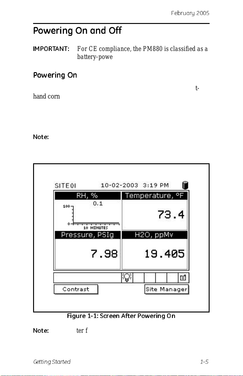
checks. The screen then appears similar to the one shown in
Figure 1-1 below.
Note:
If the meter displays a Probe Reminder mess age, press
[ENTER].
Figure 1-1: Screen A ft e r Powe rin g On
Note:
Getting Started 1-5
If the meter fails any of these test s, contact GE
Infrastructu re Sensing.
Page 15
February 2005
Powering Off
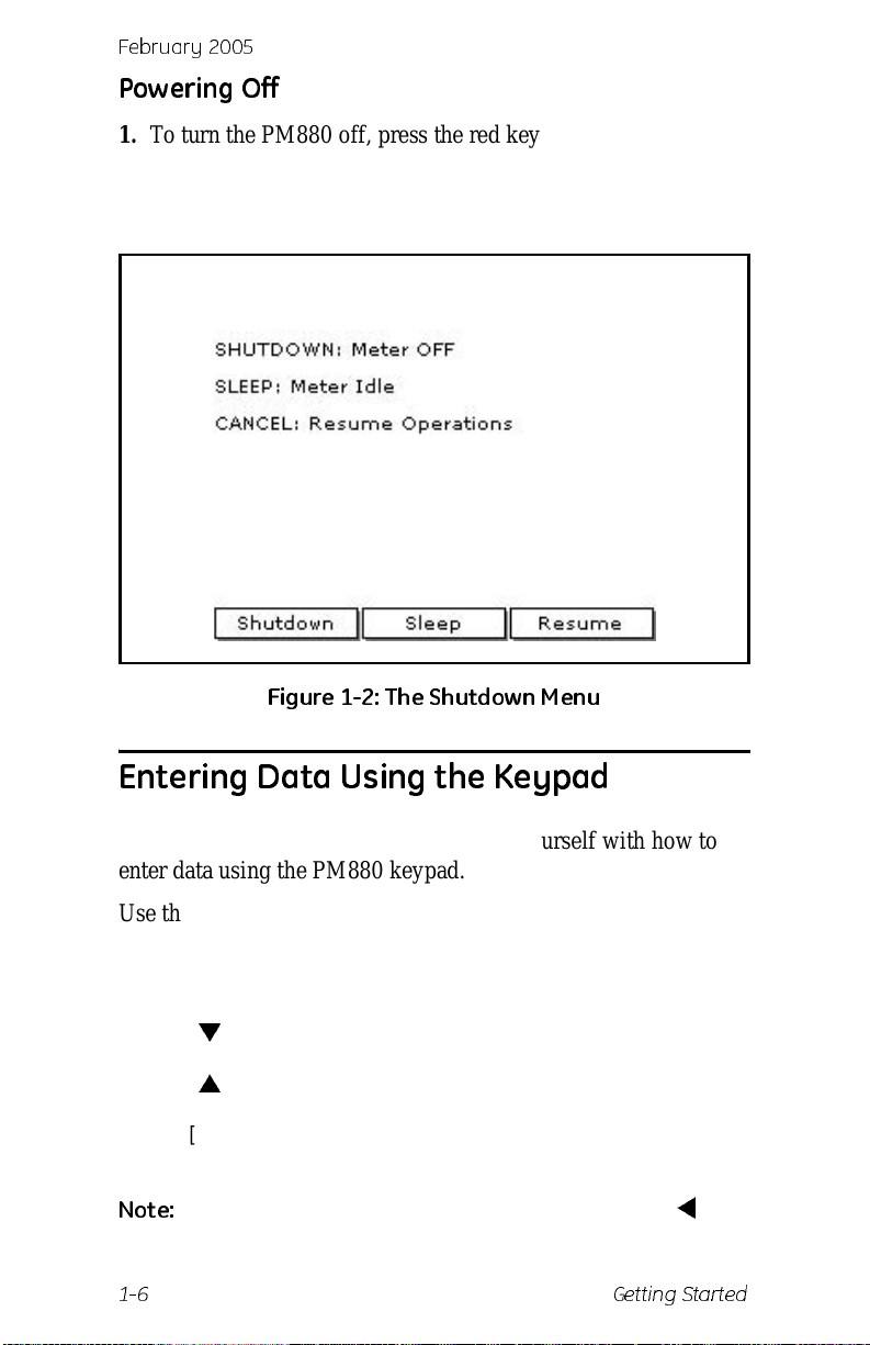
1. T o turn the PM880 off, press the red key for 3 seconds. The
screen now appears similar to Fig ure 1-2 below.
2. Press
[F1] to shut down the PM880.
Figure 1-2: The Shutdown Menu
Entering Data Using the Keypad
Use the informatio n below to f a milia rize yours elf wi th how to
enter data using the PM880 keypad.
Use the arrow keys to scroll to a menu topic and then press
[ENTER] to open the menu item.
When entering data into a menu window, press:
• The [
• The [
] key to scroll forward through the menu options.
] key to scroll back through menu options.
• The [F2] key (Cancel) or the [ESC] key to exit a menu at any
time and return to Operate Mode without changing data.
Note:
1-6 Getting Started
If you en t er an i nco r rect numeric va l ue , p r e ss the [] key
to erase the last digi t ent ered.
Page 16
Febr uar y 20 0 5
Entering Setup Data
For immediate operation, the PM880 requires only a moisture
probe and its corresponding c alibration data. You should enter
data for each site where you plan to make a measurement. Once
entered, you can save it into a file that can be recalle d at the
measurement site. Use the sections that follow to program your
meter.
Note:
The PM880 has a dditional menus that e nable y ou to tailo r
measurements as specifically as possible to your
particular applic ation. For more infor mation on menu
options refer to Chapter 4, Using Special Features.
Selecting Probe Type
Use the steps below to select the probe type for the measurement
site. Refer to Figure 1-9 on page 1-19 for a menu map.
Note:
1. If the menu is not active, press
2. Use the arrow key to scro ll to Program and press
3. Use the arrow key to scro ll to Probe and press
You may also enter a constant value for moisture,
temperatur e or pressure measurement (rather than a live
input). For more information refer to Entering Constants
and User Functions on page 4-10.
[MENU].
[ENTER].
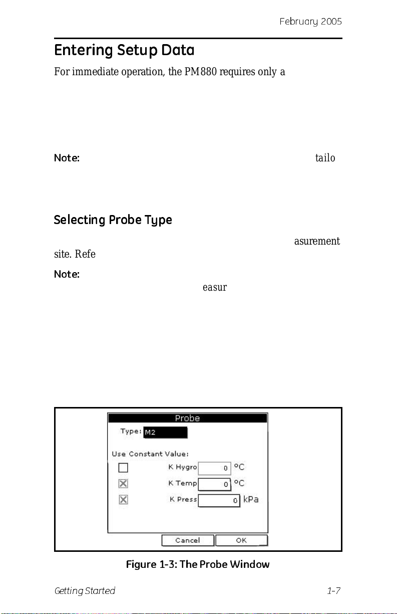
[ENTER]. The
screen appears simila r to Figur e 1-3 below.
Figure 1-3: T he P robe W i nd ow
Getting Started 1-7
Page 17
February 2005
Selecting Probe Type (cont.)
4. At Type, press [ENTER] to open the drop-down list of probe
types.
Note:
5. Use the arrow keys to scroll to the desired selection and press
6. Press
If you do not know the probe type, refer to the Calibrati on
Data Sheet.
[ENTER].
[F3] (OK) to exit.
What’s Next?
Do one of the following:
• If you are using an M and TF Series probes, proceed to
Entering Calibrati on Dat a on the next page.
• If you are using an MIS Probe (MISP), proceed to
Displaying Measurements on page 1-15.
Note:
If you h a v e an MISP prob e tha t was se nt back to the
factory for calib ratio n without the electr onic s module you
need to enter calibration data as de scribed in Entering
Calibration Data on the next page .
1-8 Getting Started
Page 18
Febr uar y 20 0 5
Entering Calibration Data
The PM880 needs moisture and/or press ure calibration data for
probes. You need to enter this data
• when setting up a new unit
• sent a probe(s) back to the factory for calibration
Be sure you have the Calibration Data Sheets that are supplied
with each GE Infrastructur e Sensing probe. Each Calibration
Data Sheet consists of a list of data points that you will need to
enter or verify, and lists its corresponding probe serial number.
Calibration Data Sheets are usual ly packed insi de the probe cases.
Since the PM880 enables you to use more than one probe, the
meter provides a place to enter the probe serial number to help
you match the probes to the corresponding site files. The probe
serial number is stored as part of the site file.
Use the sections on the following pages to enter the serial
number, moisture and pressure calibration data for the probes.
Entering Probe ID
1. If the menu is not active, press [MENU].
2. Use the arrow key to scro ll to Program and press
3. Use the arrow key to scro ll to Calibrate and press
4. Use the arrow keys to scroll to the Probe ID tab and press
[ENTER]. A screen similar to Figure 1-4 below appears.
Figure 1-4: T he Probe ID W i nd ow
Getting Started 1-9
[ENTER].
[ENTER].
Page 19
February 2005
Entering Probe ID (cont.)
5. Use the arrow keys to scroll to S/N and press [ENTER].
6. Use the numer ic keys to ent er the serial num b er from the
Calibration Data Sheet and press
is also scribed on the hex nut of the moisture probe.
7. Use the arrow keys to scroll to the suf fix box and press
[ENTER] to open the drop-down list.
8. Use the arrow keys to scroll to the desire d suf fix and press
[ENTER].
[ENTER]. The serial number
9. Press
[F3] (OK) to exit.
Entering Moisture Calibration Data
You only need to enter calibration data for M and TF Series
®
probes. The Moisture Image
calibration data in its electronics module, and uploads it into the
PM880 memory when needed.
Note:
It is not necessary to enter cali bration data for the
Moistur e Image Series (MISP) unless you send the probe
back to the factory for calibr ation without its electronics
module. If this is the case, you must manually ent er the
calibration data as described below.
Enter moisture calibr ation data (MH or FH) and dew point
readings (up to 20 data points) for the moisture probe as
described below. Refer to Figure 1-9 on page 1-19 for a menu
map.
Note:
If you are using a MISP probe and do not need to enter
data, proceed to Displaying Measurements on page 1-15.
1. If the menu is not active, press
Series (MISP) probe stores all
[MENU].
2. Use the arrow key to scro ll to Program and press
3. Use the arrow key to scro ll to Calibrate and press
[ENTER].
[ENTER].
4. If necessary, use the arrow key to scroll to Hygro and press
[ENTER]. The screen appears similar to Figur e 1-5 on the next
page.
1-10 Getting Started
Page 20
Febr uar y 20 0 5
Entering Moisture Calibration Data (cont.)
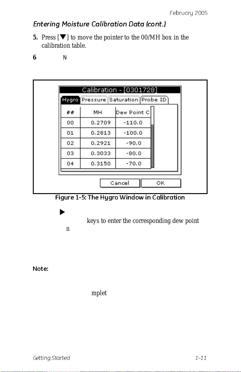
5. Press [] to move the pointer to the 00/MH box in the
calibration table .
6. Press
[ENTER] to change the value. Use the numeric keys to
enter the desired MH or FH value, and press
[ENTER].
Figure 1-5: The Hygro Window in Calibration
7. Press [] to move to the next text box, and press [ENTER].
Use the numeric keys to enter the corresponding dew point
reading and press
[ENTER].
8. Use the arrow keys to scroll to additiona l data points and
repeat steps 5, 6 and 7 until you have entered the value s for
each data point.
Note:
9. When you have completed entering values, press
Test Equipment Depot - 800.517.8431 - 99 Washington Street Melrose, MA 02176
Getting Started 1-11
To insert an additional data point, press [F1] (Insert).
To delete a data point, press
FAX 781.665.0780 - TestEquipmentDepot.com
[F2] (Delete).
[F3] (EXIT).
Page 21
February 2005
What’s Next?
Do one of the following:
• If the probe has a pressure transducer, proce ed to step 3 in
Entering Pre ssure Calibration Data on the next page.
• If the probe does not have a pressure transducer, press [F3]
(OK) and proceed to Dis playing Measurements on
page 1-15.
1-12 Getting Started
Page 22
Febr uar y 20 0 5
Entering Pressure Calibration Data
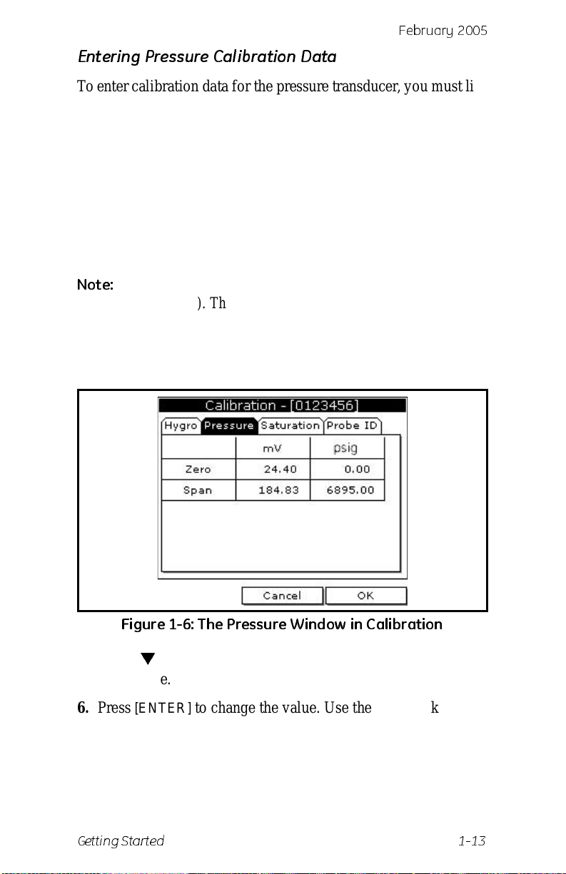
T o enter calib ration dat a for the pressur e transduc er , you must list
the zero and span range in mV (or FP) and psig. Refer to
Figure 1-9 on page 1-19 for a menu map.
1. If the menu is not active, press
[MENU].
2. Use the arrow key to scro ll to Program and press
3. Use the arrow key to scro ll to Calibrate and press
4. Use the arrow key to scro ll to Pressure and press
The screen appears similar to Figure 1-6 below.
Note:
The corresponding mV value can be in psig (English) or
kPa (metric). The supplied Calibration Data Sheets list
these values in psig. If you want to change the sys tem
units to English, refer to Selecting English and Metric
Units on page 4-2.
[ENTER].
[ENTER].
[ENTER].
Figure 1-6: T he P ressure W i nd ow in Cal ib rat ion
5. Press [] to move the pointer to the Zero/mV (Zero/FP) box
in the table.
6. Press
[ENTER] to change the value. Use the numeric keys to
enter the desired value and press
[ENTER].
7. The corresponding pressur e value box is highlighted. Use the
numeric keys to enter the corresponding pressure value and
press
[ENTER].
Getting Started 1-13
Page 23
February 2005
Entering Pressure Calibration Data (cont.)
8. The span mV box is highlighted. Repeat steps 5, 6 and 7 to
ente r the Span values.
9. When you have completed entering values, press
10.Press
[F3] (OK) and proceed to Displaying Measurements on
the next page.
[F3] (Exit).
1-14 Getting Started
Page 24
Febr uar y 20 0 5
Displaying Measurements
The PM880 can display one to four measurement parameters
simultaneously. There are two parts for displaying measurements:
selecting the number of mea surements a nd th en selectin g the type
of measurements. Refer to Figure 1-9 on page 1-19 for a menu
map.
Selecting the Number of Measurements
1. If the menu is not active, press [MENU].
2. Use the arrow keys to scroll to Site and press
3. Use the arrow keys to move t o the desired number of views or
measurement windows (1 View, 2 Views, etc.).
4. Press
[ENTER] at your selection. The screen displays the
designated number of views (meas urement windows).
[ENTER].
Selecting the Types of Measurements
1. Press [SEL] or arrow keys to move the pointer to the window
you want to change and press
2. Use the arrow keys to scroll to Measurement and press
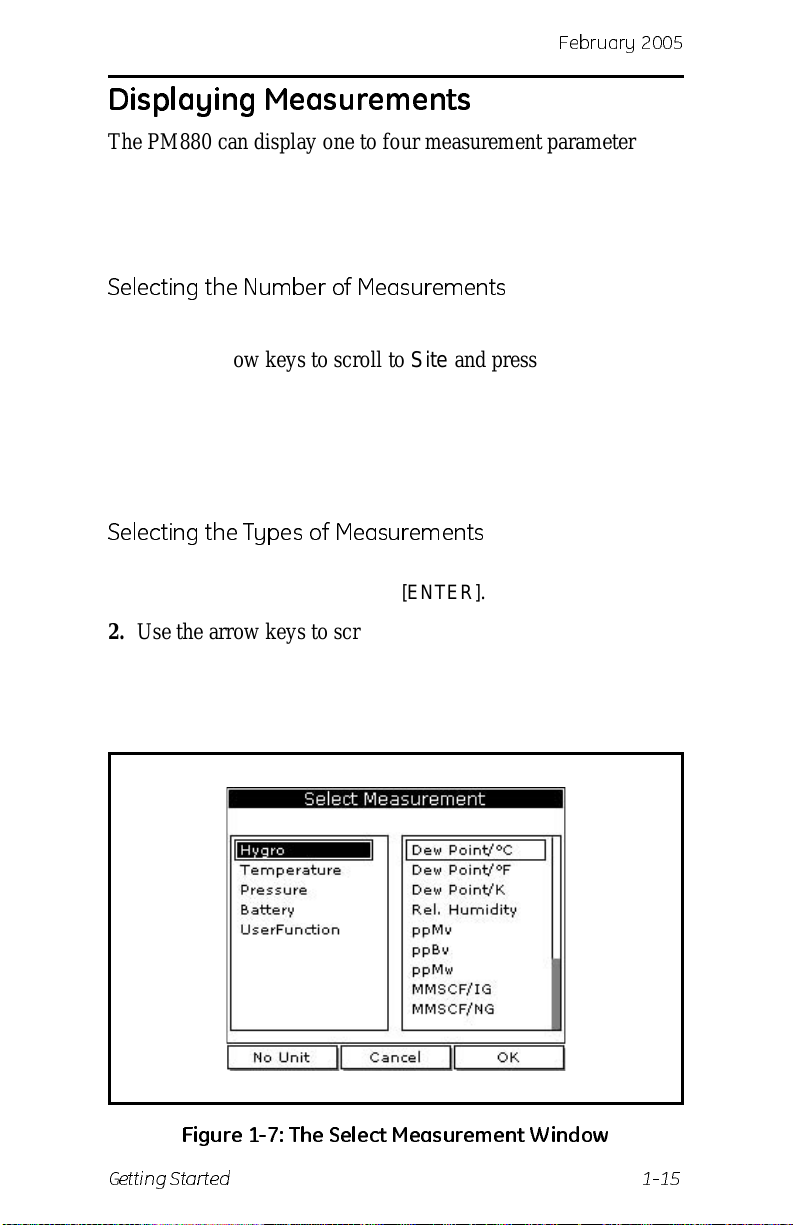
[ENTER]. The screen appears similar to Fi gure 1-7 below. The
left column displays the five measu rement types and the right
column displays the measurement units.
[ENTER].
Figure 1-7: T he Sel e ct M easu rem e nt W i nd ow
Getting Started 1-15
Page 25
February 2005
Displaying Measurements (con t.)
Selecting the Types of Measurements (cont.)
3. Use the arrow keys to scroll to the desired measurement type
and press
4. Use the arrow keys to select the desired measurement unit (or
diagnostic paramete r).
[SEL].
Note:
5. Press
6. Repeat this section for displaying other measurements.
Press [F3] (No Unit) to display a measur ement with no
units.
[F3] (OK).
1-16 Getting Started
Page 26
Febr uar y 20 0 5
Saving Data in a Site File
A site file contains probe ID, calibration data and display setup
information into a file so it can be recalled at the measurement
site. Use the following steps to store the data you have entered
into a file (refer to Figure 1-9 on page 1-19 for a menu map):
Accessing the Site Manager
1. If the menu is not active, press [MENU].
2. Use the arrow key to scro ll to Site and press
3. Use the arrow key to scro ll to Site Manager and press
[ENTER].
4. Press
5. Use the arrow key to scro ll to File and press
[MENU].
[ENTER].
[ENTER].
Entering a Site Name
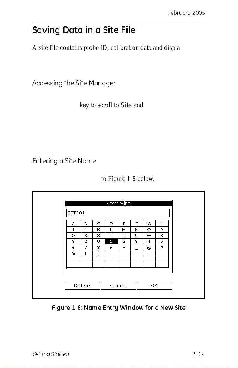
1. Use the arrow keys to scroll to New and press [ENTER]. The
screen appears simila r to Figur e 1-8 below.
Figure 1-8: Na m e En try W i n dow for a Ne w Sit e
Getting Started 1-17
Page 27

February 2005
Saving Data in a Site File (cont.)
2. The PM880 displays a defa ult name for th e file. If you want to
keep the default name, skip to step 4. Otherwise, use
erase the name and use the arrow keys to scroll to the desired
letter or number and press
3. Repeat this procedure until you have created the desired site
name of up to eight characters.
[ENTER].
[F1] to
4. When you have finished, press
5. The PM880 prompts you to save the site file as a template.
This is useful if you need to create multiple sites with similar
data. At the prompt, do one of the following:
[F3] (OK).
• Press [F2] (No) if you do not need to use a template, or
• Press [F3] (Yes) if you do want to use it as a template.
Note:
6. Press
7. Press
What’s Next?
Do one of the following:
If you ar e saving a new file as a template, the PM880 will
ask if you want to Save Current Site, press
[F3] (Yes).
[F3] (Exit).
[MENU]. The new site name is displayed in the upper
left corner of the screen. You have completed entering site
data.
[F2] (No) or
• If you are done entering site data, proceed to the next
chapter, Taking Measurements.
• If you need to enter infor mation for another site, go back to
Entering Setup Data on page 1-7.
Note:
1-18 Getting Started
If you need to cre ate multiple site files with simil ar data,
you can save time by creating one site file and then using
Save As in the Site Manager to create a copy of that site
file with a different name. Refer to Renaming a Site File
on page 6-6.
Page 28
b
Menu
ruary 2005
Fe
Program
Probe
M2 M2T TF MISP No n e
Hygro Constant
Tempe ra ture Constant
Pressure Constant
Calibrate
Pres s u re Hygro
MH (FH)
Dew Point
Zero FP
Zero kPa
Span FP
Span kPa
Probe ID
S/N
Site
Manager Save
1 View 2 Views 3 Views 4 Views
File
New
Name
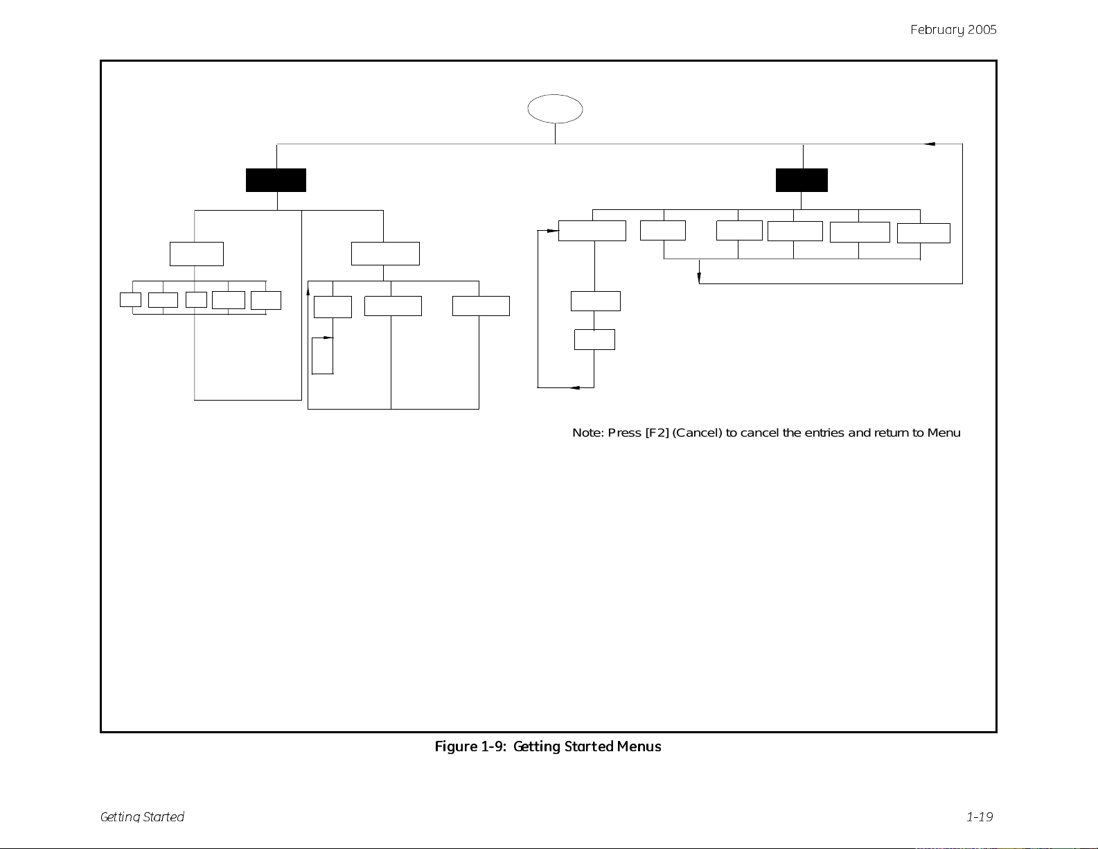
Note: Press [F2] (Cancel) to cancel the entries and return to Menu.
Press [F3] (OK) to confirm the entries and return to Menu.
Figure 1-9: Getting Started Menus
Get ti ng St a rt e d 1-19
Page 29
Febr uar y 20 0 5
Chapter 2
Taking Measurements
The PM880 hygrometer is part of measurement system that
consists of the electronics, cable, probe and optional sample
system. Once the electronics are properly prog rammed, you must
connect the sample system and probes to begin taking
measurem ent s . This chap ter dis cu ss es the ste p s neede d to beg i n
taking basic measurements.
Note:
Refer to Appendix A, Measurement Considerations, for
more information on selecting measurement sites and
sample system construction.
• Installing the Probe into a Sample System
• Connecting the Sample System to the Process
• Connecting the Probe to the Elect ronics
• Recalling a Site File
• Operating the Sample System
• Conducting a Leak Te st
• Shutting Down the Sample System
Taking Measurements 2-1
Page 30
February 2005
Installing the Probe into a Sample System
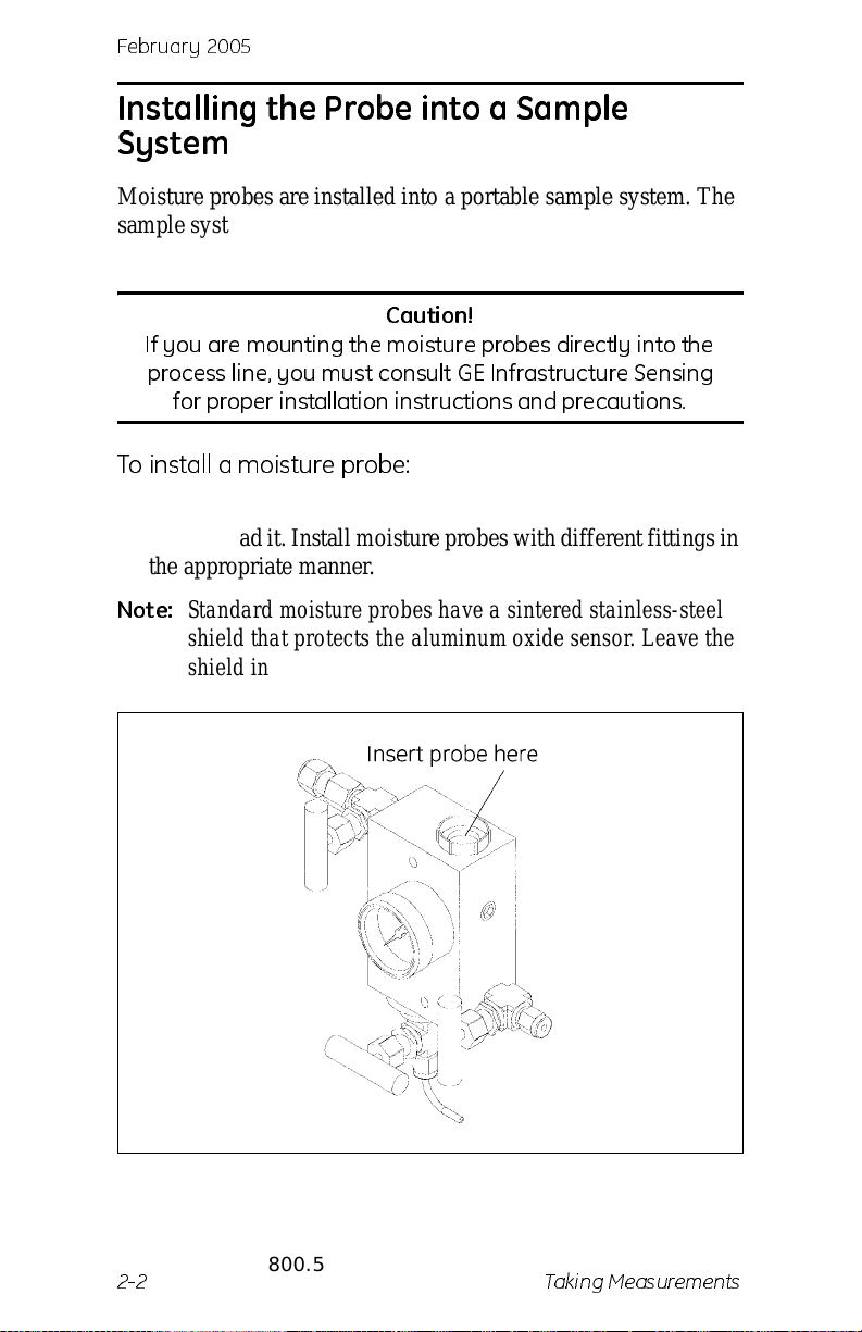
Moisture probes are inst all ed into a portable sample system. The
sample system pro tects the probes fro m coming into contact with
damaging el em en ts in the proc es s.
Caution!
If you are mo un t in g th e moist u re probes d ire ctl y in t o th e
process line, you must consult GE Infrastructure Sensing
for proper installation instructions and precautions.
To install a moisture probe:
1. Screw the probe into the receptacle fitting, making sure not to
cross thread it. Insta ll moisture probes with dif ferent fit tings in
the appropriate manner.
Note:
2. Hand-tighten the probe in a clockwise direction , then tighten it
Stand ard moisture probes have a sintered stainless-steel
shield that protects the aluminum oxide sensor. Leave the
shield in place for maximum protection.
an additional 1/8 turn with a wrench .
Test Equipment Depot - 800.517.8431 - 99 Washington Street Melrose, MA 02176
2-2 Taking Measurements
FAX 781.665.0780 - TestEquipmentDepot.com
Page 31
Febr uar y 20 0 5
Connecting the Sample System to the Process
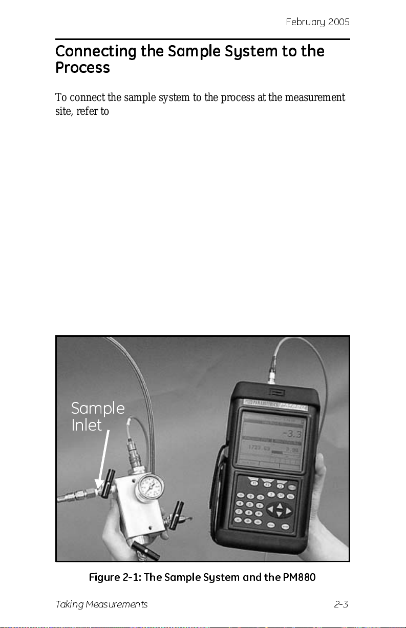
T o connect the sample system to the process at the measurement
site, refer to Figure 2-1 below and complete the following steps:
1. Crack open the existing pipeline sample tap valve to clean the
sample tap.
2. Close the pipeline sample tap val ve.
3. Remove the sample system from its case.
4. Be sure the sample system inlet needle valve is closed and the
filter/coale scer outlet needle valve and sample outl et needle
valve are open.
5. Connect the sample system to the sample tap. We recommend
using 1/4” sta inless s teel tubing. The dista nce from the sa mple
tap to the sample system should be a short as possible,
typically 5 to 15 feet (1.5 to 4.5 m) male NPT process
connection provided.
Sample
Inlet
Figure 2-1: T h e Sa mp le Sy st e m and th e P M 880
Taking Measurements 2-3
Page 32
February 2005
Making Probe Connections
Use the following steps to make probe connections:
1. Make sure the PM880 is turned off.
2. Connect the cable to the probe by insert ing the bayonet-type
connector ont o the probe and twist ing the shell cloc kwise until
it snaps into a locked position.
Note:
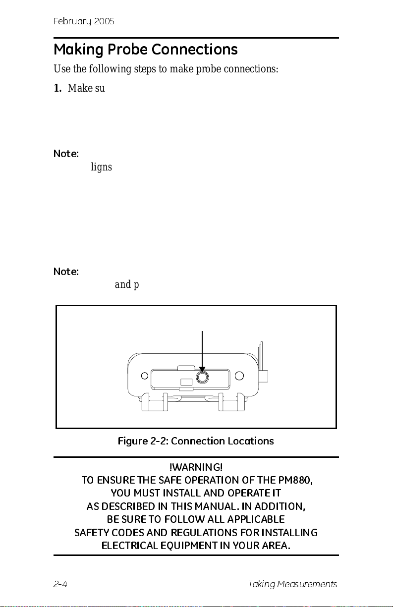
3. Connect the other end of the probe cable to the top of the unit
Note:
The connector on the probe cable must be rotated until it
aligns with the pins in the probe connector, before the
cable may be properly inserted into the probe and
secured.
by aligning the red dot on the cable connector at the 12
o’clock position. See Figure 2-2 below for the connector
location.
Remove the pr obe cable by pul ling back the spri ng-loaded
sleeve and pulling the cable out of the connector.
Probe Input
Figure 2-2: Connection Locations
!WARNING!
TO ENSURE TH E SAFE O PER ATION O F THE P M 880 ,
YOU M U ST INSTALL AND OP ER ATE IT
AS DESCR I BED IN TH IS M A NUA L. IN AD D IT I O N,
BE SURE TO FOLLOW ALL APPLICABLE
SAFET Y COD ES A ND REGU LATIONS FOR IN STALLING
ELECTRICAL EQUIPMENT IN YOUR AREA.
2-4 Taking Measurements
Page 33
Febr uar y 20 0 5
Recalling a Site File
T o begin taking measurements you must recall the site file that
contains data for the measurement site where you want to take
measurements.
Accessing the Site Manager
1. If the menu is not active, press [MENU].
2. Use the arrow key to scro ll to Site and press
[ENTER].
3. Use the arrow key to scro ll to Site Manager and press
[ENTER].
Retrieving the Site File
1. Use the arrow key to scroll to the desired site and press
[MENU].
2. Use the arrow key to scro ll to File and press
3. Use the arrow key to scro ll to Open and press
4. The PM880 asks you to confirm, press
5. Press
6. Press
[F3] (Exit).
[MENU]. The PM880 displa ys the se lecte d site f ile in th e
upper-left of the screen.
[ENTER].
[ENTER].
[F3] (Yes).
Taking Measurements 2-5
Page 34
February 2005
Operating the Sample System
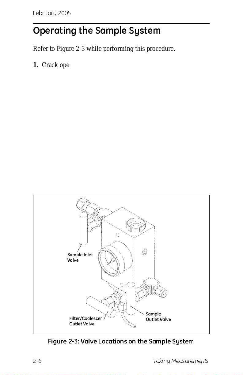
Refer to Figure 2-3 whi l e perfo rm i ng th is pr oced u re .
1. Crack open the sample inlet valve allowing a low volume
purge of the sample system.
2. Very slowly open the inlet value allowing it to reach process
pressure.
3. Begin closing the filter/coalescer outlet needle valve and the
sample outlet valve until both valves are nearly closed.
4. Adjust the sample outlet needle valve and the filter/coalescer
outlet valve until you feel a slight pressu re against your finger
at the venting tubes.
5. Open the inlet valve fully. Be sure the flow out of the venting
tubes remains the same as in step 4. To prevent physical
damage, do not subject the probe to excessive flow.
6. Turn on the PM880.
Figure 2-3: Va lve Loca ti on s on th e Sam pl e S yst e m
2-6 Taking Measurements
Page 35
Febr uar y 20 0 5
Conducting a Leak Test
It is important to elim i nat e all leak s for safe t y reas ons an d to be
sure that measurements are not affected by ambient
contamination. Use Snoop Leak Detector or a soapy solution to
verify that all connections, valves and fittings are leak tight.
Tighten any fittings wh ere a leak is de tect ed .
Shutting Down the Sample System
1. Close the sample outlet needle valve.
2. Slowly open the filter/ coalescer outlet needle valve sev era l
turns to blow out any contaminants that may have
accumulated in the coales cer, valve, or venting tube.
3. Slowly close the sample inlet valve and allow the sample
system to depressurize at a rate of approximately 10 psig per
second.
4. Close the sample tap valve (permanently mounted on the
pipeline).
5. Crack the inle t needl e v alv e to relie v e the pres s ure b et ween
the sample tap valve and the inlet needle valve.
6. Complete ly clo s e all thre e sa mpl e sys tem va lves .
7. Remove the sample system from the process, while keeping
all valves fully closed to avoid moisture contamination from
the ambient air.
Taking Measurements 2-7
Page 36
Febr uar y 20 0 5
Chapter 3
Using the PM880 Screen
Use the secti ons that follow to setup and make adjustm ents to the
PM880 screen. This chapter discusses the following:
• Screen Components - page 3-2
• Setting Up the Scr een to D ispl ay Me as urem en t s - page 3 -4
• Creating Function Key Shortcuts - page 3-9
• Using the Backlight - page 3-10
• Adjusting the Contrast - page 3-11
• Taking a Bitmap Screen Capture (Snapshot) - page 3-12
Using the PM880 Screen 3-1
Page 37
February 2005
Screen Compon en ts
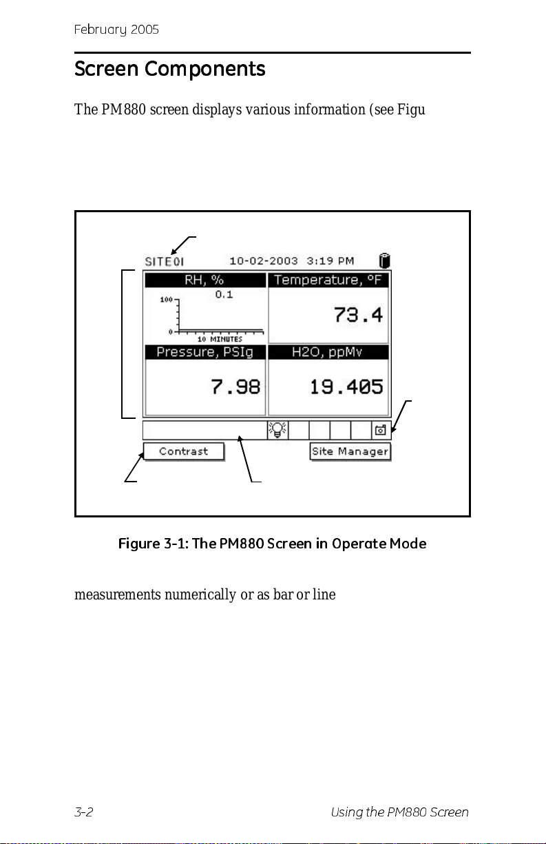
The PM880 screen displays variou s information (see Figure 3-1
below). The top line of the screen is the status bar that displays
the current site being use d, tim e, date and battery status during
normal operati on. However, the status bar changes to a menu bar
when programming.
Status/Menu Bar
Work
Area
System
Tray
Function Keys
Error Messages
Figure 3-1: The PM880 Screen in Operate Mode
The middle of the screen is the work area that displays
measurements numerica lly or as bar or line graphs. During
programming, the work area displays menu prompts. The bottom
of the screen displays error messages (see Error and Screen
Messages on page 8-26 for more details), the system tray, and
the function keys.
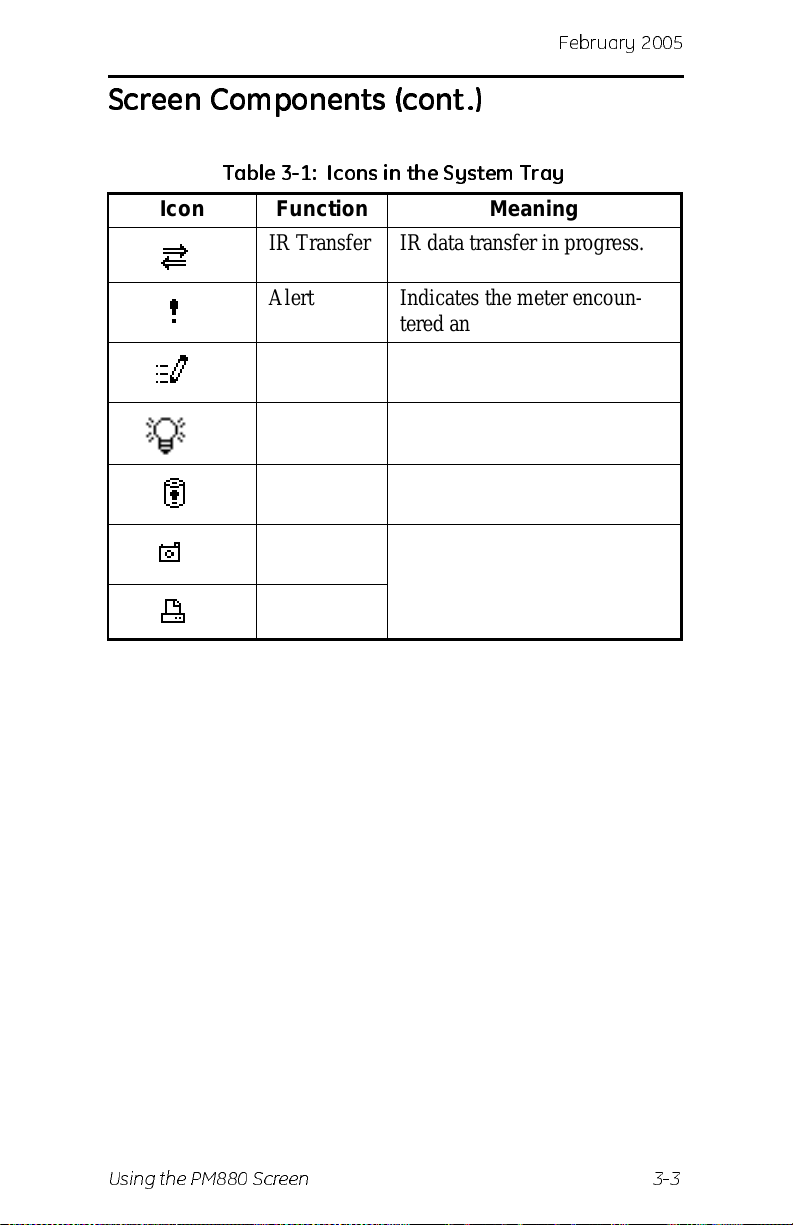
The system tray displays icons tha t indicate meter operations not
otherwise shown (see Table 3-1 on the next page for a list of
icons). The three function keys (F1, F2 and F3) have different
functions, depending on the task you are performing.
3-2 Using the PM880 Screen
Page 38
Screen Compon en ts (cont.)
Table 3- 1: Icon s in th e Sy st em Tray
Icon Function Meaning
IR Transfer IR data transfer in progress.
Alert Indicates the meter encoun-
tered an error in opera tio n.
Log Indicates a log is pending (no
marks) or running (marks).
Backlig ht Indicates tha t back li ght has
been activat ed.
Febr uar y 20 0 5
Low Battery Alert
Snapshot
(To file)
(To Printer)
Indicates 10 minute s or l ess of
battery run time.
Indicates that the Snapshot
function has been activated, so
users can take screen captures.
Using the PM880 Screen 3-3
Page 39
February 2005
Setting Up the Screen to Display Measurements
The PM880 can display one to four measurements
simultaneously. After you select how many measurements to
display, you can select the type of measurements (d ew point,
temperature, etc. ) and the format (numeric, line or bar graph). In
addition, the PM880 offers various options for displaying data
numerically and graphically.
This section consists of the following:
• Selecting the Number of Views (Measurements) - page 3-4
• Selecting the Types of Measurements - page 3-4
• Selecting Numeric, Line or Bar Graph Format - page 3-5
• Setting Up the N umeric Format - page 3-6
• Adjusting the Line/Bar Graph Sca le - page 3-7
Use the section(s) that fo llow to set up the PM880 screen.
Selecting the Number of Views (Measurements)
1. If the menu is not active, press [MENU].
2. Use the arrow keys to scroll to Site and press
3. Use the arrow keys to move t o the desired number of views or
measurement windows (1 View, 2 Views, etc.).
4. Press
[ENTER] at your selection. The screen displays the
designated number of views (meas urement windows).
[ENTER].
Selecting the Types of Measurements
1. Press [SEL] to move the pointer to the window you want to
change and press
2. Use the arrow keys to scroll to Measurement and press
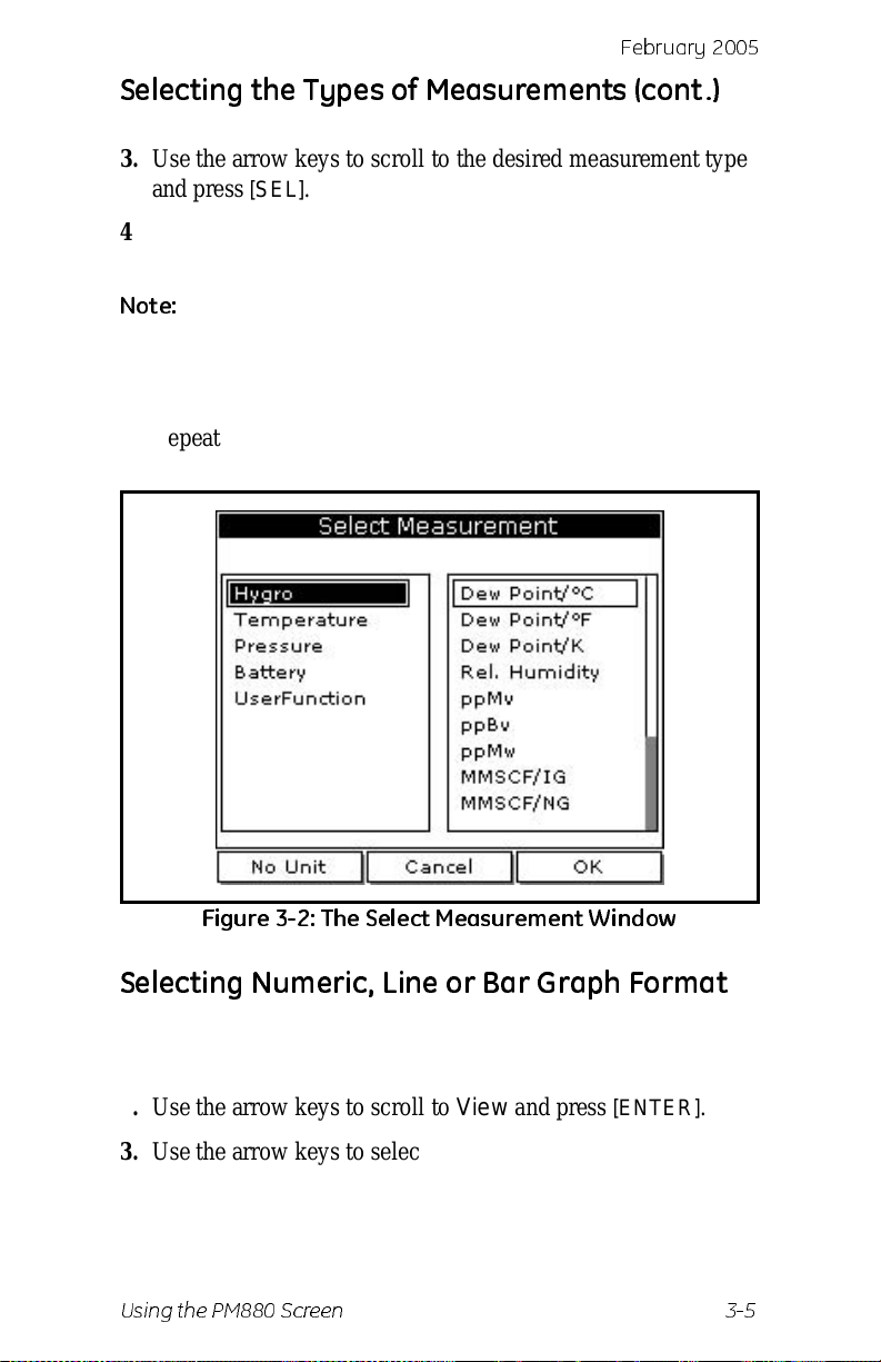
[ENTER]. The screen appears similar to Figur e 3-2 on the next
page. The left column displays the five measurement types
and the right column displays the measurement units.
3-4 Using the PM880 Screen
[ENTER].
Page 40
Febr uar y 20 0 5
Selecting the Types of Measurements (cont .)
3. Use the arrow keys to scroll to the desire d measure ment type
and press
4. Use the arrow keys to select the desired measurement unit (or
diagnostic paramete r).
[SEL].
Note:
Press [F3] (No Unit) to display a measurement with no
units.
5. Press
[F3] (OK).
6. Repeat this section for displaying other measurements.
Figure 3-2: T he Sel e ct M easu rem e nt W i nd ow
Selecting Numeric, Line or Bar Graph Format
1. Press [SEL] to move the pointer to the window you want to
change and press
2. Use the arrow keys to scroll to View and press
3. Use the arrow keys to select the desired format and press
[ENTER].
The PM880 displays the desired format and returns to taking
measurements.
Test Equipment Depot - 800.517.8431 - 99 Washington Street Melrose, MA 02176
Using the PM880 Screen 3-5
FAX 781.665.0780 - TestEquipmentDepot.com
[ENTER].
[ENTER].
Page 41
February 2005
Setting Up the Numeric Format
1. Press [SEL] to move the pointer to the window you want to
change and press
[ENTER].
2. Use the arrow keys to scroll to Format and press
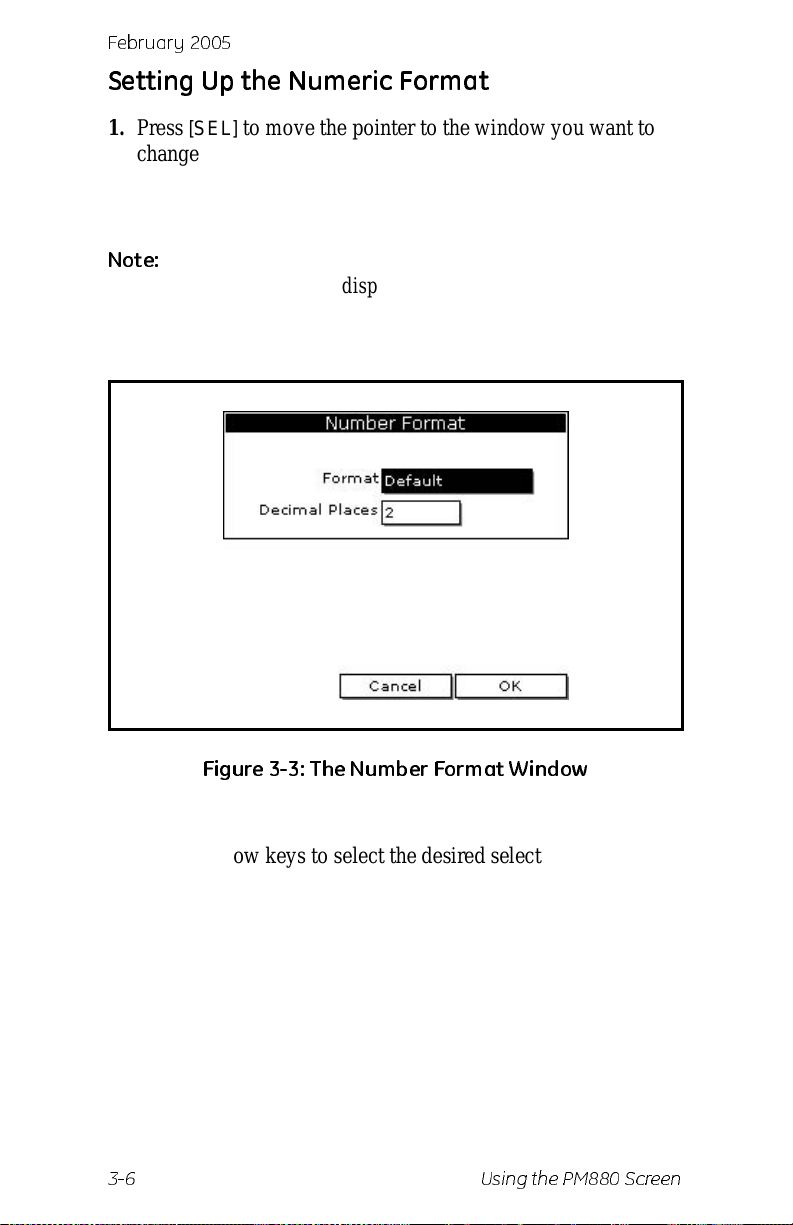
The screen appears similar to Figure 3-3 below.
Note:
If FORMAT does not appear in the menu, move to a
window that is not displaying a line or bar graph, or
change the window format to numeric as describe d in the
prev ious section.
Figure 3-3: T h e Nu m b er Format W in d ow
[ENTER].
3. Use the arrow keys to scroll to Format and press [ENTER].
4. Use the arrow keys to select the desired selection and press
[ENTER]. You can select from the following:
• Default - displays the factor y default number of decimal
digits for the selected measurement.
• Fixed Decimal - specify how many digits to the right of the
decimal
• Scientific format - displays the value in mantissa exponent
format (expressed to the power of 10).
3-6 Using the PM880 Screen
Page 42
Febr uar y 20 0 5
Setting Up the Numeric Format (cont .)
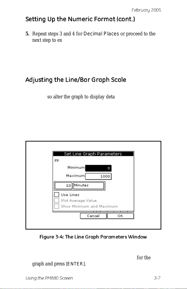
5. Repeat steps 3 and 4 for Decimal Places or proceed to the
next step to exit. You can select from 0 to 4 places.
6. Press
[F3] (OK).
The PM880 displays the new format and returns to taking
measurements.
Adjusting the Line/Bar Graph Scale
The scale of the line and bar graph can be adjusted at any time.
You can also alter the graph to display details such as...
1. Press
2. Use the arrow keys to scroll to Limits and press
[SEL] to move the pointer to the window you want to
change and press
[ENTER].
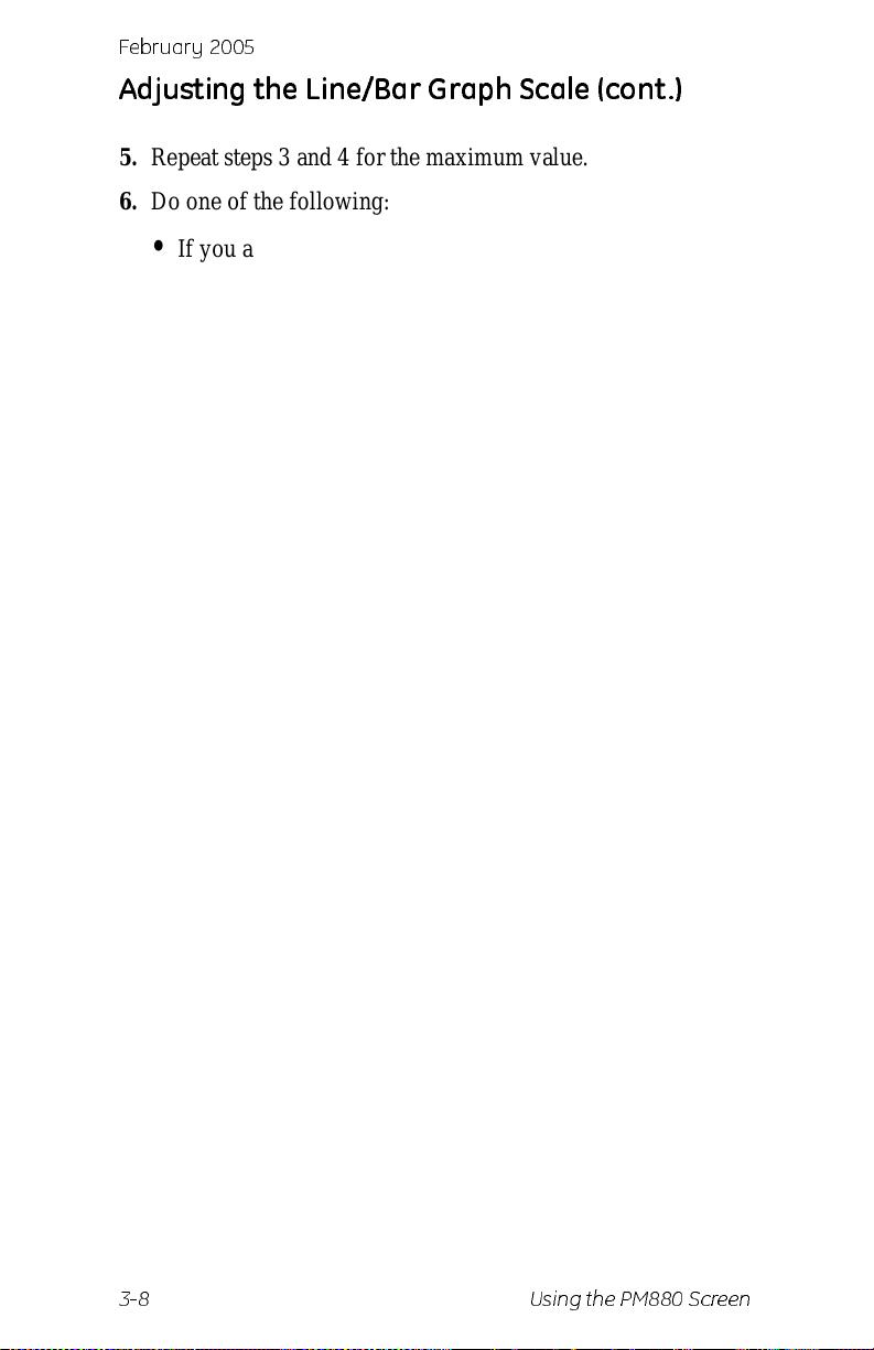
screen similar to Figure 3-4 below appears
[ENTER]. A
Figure 3- 4: Th e Lin e Graph Pa ram eters Wi n dow
3. Use the arrow keys to scroll to Minimum and press [ENTER].
4. Use the numer ic keys to ent er the mini m um value for the
graph and press
Using the PM880 Screen 3-7
[ENTER].
Page 43
February 2005
Adjusting the Line/Bar Graph Scale (cont .)
5. Repeat steps 3 and 4 for the maximum value.
6. Do one of the following:
• If you are using a line graph, proceed to step 7.
• If you are using a bar graph, proceed to step 10.
7. Use the arrow keys to scroll to the time interval and press
[ENTER].
8. There are two boxes for entering the time interval. The first
box is for a number (1, 2, etc.). The second box asks for the
interval (second s, mi nutes, hours or days). Use the numeric
keys or arrow keys to select the desir ed interval and press
[ENTER].
9. The last three selecti ons enable you to enhance the line graph
details. Use the arrow keys to scroll to the desired entry and
press
[ENTER]. An X in the box activates the option. Choose
from the following:
• Use lines (connect point s on graph with lines)
• Plot average value (not currently available)
• show minimum and maximum (not currently available)
10.Press
The PM880 displays the new format and returns to taking
measurements.
3-8 Using the PM880 Screen
[F3] (OK).
Page 44
Febr uar y 20 0 5
Creating Function Key Shortcuts
The three funct ion keys at th e bot tom of the PM880 scree n can be
customized to provide shortcuts to the most commonly used
functions. For example, the F1 key can be assigned to go directly
to the Log Manager . Once assigned, a function key can also be
cleared. Use the sections below to performed the desired
function.
Assigning/Re-assigning a Function Key
The function keys can be assigned using two methods as
described below.
Note:
Method 1 : Us ing the Site M anager
1. If the menu is not active, press
2. Use the arrow key to scro ll to Site and press
3. Use the arrow key to scro ll to FKeys and press
4. Use the arrow keys to scroll to the desire d key and press
5. Use the arrow keys to scroll to the desired function from the
6. Press
The PM880 returns to taking measuremen ts. The newly assigned
function appears above the assigned function key.
Method 2 : Us ing the Prog ram Menus
1. Use the keypad to go to the desired functio n that you want to
2. Press the desired function key. A window appears with the
You can re- assign the function key at any time by
assigning a different function.
[MENU].
[ENTER].
[ENTER].
[ENTER].
displayed list.
[F3] (YES).
assign to the function key.
question, “Assign current menu command (XX) to FKeyX?”
3. Press
The PM880 returns to taking measuremen ts. The newly assigned
function appears above the assigned function key.
Using the PM880 Screen 3-9
[F3] (OK).
Page 45
February 2005
Clearing a Function Key
1. If the menu is not active, press [MENU].
2. Use the arrow key to scro ll to Site and press
3. Use the arrow key to scro ll to FKeys and press
4. Use the arrow ke ys to scroll to Clear F1 (F2 or F3) and press
[ENTER].
The PM880 returns to taking measurement s. The previously
assigned function is erased.
[ENTER].
[ENTER].
Using the Backlight
The PM880 has a backlight that helps in viewing data. Since the
backlight uses more energy, the PM880 has a backlight timer that
you can set to automatically turn the backlight off after a
specified time in order to cons erve battery life. The PM880 also
enables you to turn the backlight on and off manually. Use the
sections that follow to operate the backlight.
Manually Turning Backlight On and Off
To manually turn the backlight:
• On - press any key on the keypad and the backlight will
stay on for the programmed int erval. You can also press the
power key briefly (about one- half second) and the
backlight will stay on for 30 minutes.
• Off - press the red power key briefly (about one-half
second).
Setting the Backlight Timer
1. If the menu is not active, press [MENU].
2. Use the arrow key to scro ll to Meter and press
3. Use the arrow key to scro ll to Backlight and press
3-10 Using the PM880 Screen
[ENTER].
[ENTER].
Page 46
Febr uar y 20 0 5
Setting the Backlight Timer (cont.)
4. Use the arrow key to scro ll to Backlight Off and press
[ENTER].
5. Use the numeric keys to enter the number of minutes that the
backlight remains on (from 0 to 60).
6. Press
7. When you are done, press
[ENTER] to confirm the entry.
[F3] (OK).The PM880 returns to
taking measurements.
Adjusting the Contrast
To adjust the scre en co ntra s t:
1. If the menu is not active, press
2. Use the arrow key to scro ll to Meter and press
3. Use the arrow key to scroll to Contrast and press
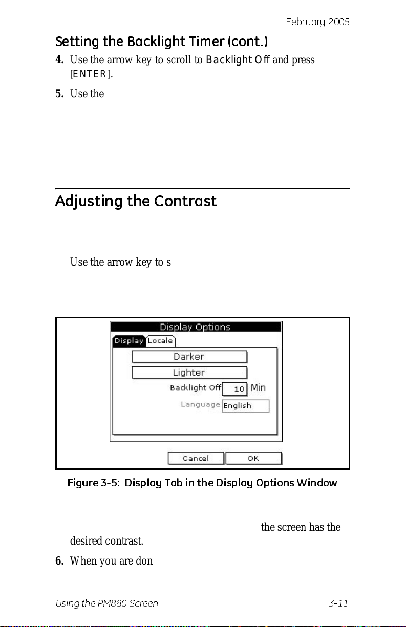
screen similar to Figure 3-5 below appears.
[MENU].
[ENTER].
[ENTER]. A
Figure 3-5 : Disp la y Ta b in th e Di spla y Op ti ons Window
4. Use the arrow keys to scroll to Darker or Lighter.
5. Press the
[ENTER] button repeatedly until the screen has the
desired contrast .
6. When you are done, press
[F3] (OK).
The PM880 returns to taking measurement s.
Using the PM880 Screen 3-11
Page 47
February 2005
Taking a Bitmap Screen Capture (Snapshot)
The Snapshot option enables you to take a screen capture of the
current scre en in bit ma p form at (.bmp). Bitma ps can b e stored in
a file or sent directly to a printer. To take a “snapshot” of the
screen:
1. If the menu is not active, press
2. Use the arrow key to scro ll to Meter and press
3. Use the arrow key to scro ll to Snapshot and press
4. Use the arrow key to scroll to the desired selection and press
[ENTER]. You can choose from the following:
[MENU].
[ENTER].
[ENTER].
• Off - to turn the snapshot feature off.
• To Printer - to send the snapshot to the printer.
• To F ile - to send the snapshot to a file.
Note:
An icon of a printer or camera appears on the system tray (see
page 3-3) indicating that you have act ivated the Snapshot option.
5. To capture a screen, press the “.” (decimal) button twice. The
Note:
In order to send a screen capture to a printer, the PM880
must be properly configured to IR transfer. Refer to
Setting Up the PM880 IR Communications on page 7-2.
meter displays a clock and the message “Scre en Dump,”
indicating that it is perf orming a screen capture.
The snapshot function is deactivated once the power is
turn e d o ff.
3-12 Using the PM880 Screen
Page 48
Febr uar y 20 0 5
Taking a Bitmap Screen Capture
(Snapshot)
6. If you selected:
• To Printer - the PM880 indicate s it is looking for a
receiving printer and then transmits the file.
Note:
If the sensor cannot location a printer, a window appears
indicating that it cannot find a device. If it locates more
than one compatible infrared device within its range, it
asks you to select the desired device.
• To F ile - the captured file appears as ScreenXX.bmp in the
Drive Mana ger. To transfer the file to a PC , follo w the
instructions in Transferring a File to a PC on page 7-8.
Using the PM880 Screen 3-13
Page 49
Febr uar y 20 0 5
Chapter 4
Using Special Features
The PM880 has a vari ety of othe r f eatures t o m ake opera tion e ven
more convenient . Below is a lis t of some of the fe atur es avail able.
For other features related to testing and service fun ctions, refer to
Chapter 8, Maintaining and Troubleshooting the PM880.
• Selecting English or Metric Units - page 4-2
• Entering Date and Time - page 4-2
• Changing the Date and T ime Appearance - page 4-3
• Adding a Message to a Site File - page 4-5
• Setting a Probe Calibrat ion Reminder - page 4-6
• Using Automatic Calibration - page 4-8
• Entering Constants and User Functions - page 4-10
• Using Computer Enhanced Response - page 4-22
• Entering Reference Data - page 4-24
• Using the Sleep Mode - page 4-26
• Displaying Meter Information - page 4-27
• Changing the Display Language - page 4-28
• Using On-Line Help - page 4-29
Using Special Features 4-1
Page 50
February 2005
Selecting English or Metric Units
The PM880 enables you to se lec t either Engl ish or Metric unit s a s
global measurement units. The selected units become the default
settings for every measurement that has the option for metric/
English units. To select the measurement units:
1. If the menu is not active, press
2. Use the arrow key to scro ll to Meter and press
3. Use the arrow key to scro ll to Units and press
[MENU].
[ENTER].
[ENTER].
4. Use the arrow keys to scroll to the desire d units and press
[ENTER].
5. Press
[F3] (OK) and then [MENU].
The PM880 returns to taking measurement s.
Entering Date and Time
The PM880 displays the current date and time above the
measurements in the upper right corner of the screen. The Date/
Time command allows you to set the date or time. The current
date and time are required for correct data logging operation.
1. If the menu is not active, press
2. Use the arrow key to scro ll to Meter and press
3. Use the arrow key to scro ll to Date/Time and press
[MENU].
[ENTER].
[ENTER].
4. Use the arrow keys to scroll to Date and press
[ENTER].
5. Use the numeric and arrow keys to enter the curr ent month,
day and year, and press
6. Use the arrow keys to scroll to T ime and press
[ENTER].
[ENTER].
7. Use the numeric and arrow keys to enter the curr ent time and
press
[ENTER].
8. Press
[F3] (OK) and then [MENU].
The PM880 returns to taking measurement s. The new date and
time are displayed.
Test Equipment Depot - 800.517.8431 - 99 Washington Street Melrose, MA 02176
4-2 Using Special Features
FAX 781.665.0780 - TestEquipmentDepot.com
Page 51
Febr uar y 20 0 5
Changing Date and Time Appearan ce
In addition to setting the correc t date and time, you can also
change its pres ent ati on to s uit loca l preferences. You can select
various date format and a time displ ay of AM/PM or 24-hour
time. To alter the time and date displ ay:
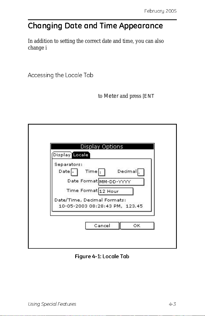
Accessing the Locale Tab
1. If the menu is not active, press [MENU].
2. Use the arrow key to scro ll to Meter and press
3. Use the arrow key to scro ll to Locale and press
screen similar to Figure 4-1 appears below.
[ENTER].
[ENTER]. A
Figure 4-1: Loc ale Tab
Using Special Features 4-3
Page 52
February 2005
Changing Date and Time Appearance (cont.)
Selecting the Separator
1. Use the arrow keys to scroll to the date separator and press
[ENTER].
2. Use the arrow keys to s croll to the desired separ ator and press
[ENTER].
3. Repeat steps 1 and 2 for the other separators.
Selecting the Date/Time Format
1. Use the arrow keys to scroll to Date Format and press
[ENTER].
2. Use the arrow keys to scroll to the desire d format a nd press
[ENTER].
3. Repeat steps 1 and 2 for the time format.
4. Press
[F3] (OK) and then press [MENU].
The PM880 returns to taking measurement s. The new date and
time format s are dis p laye d.
4-4 Using Special Features
Page 53
Febr uar y 20 0 5
Adding a Message to a Site File
The Site Manager has a command that enables you to enter a
message or de scription fo r each si te f ile ( up to 30 c haracters) . The
Site Manager displays the site message with the other file
information. To add a site message:
Accessing the Site Manager
1. If the menu is not active, press [MENU].
2. Use the arrow key to scro ll to Site and press
[ENTER].
3. Use the arrow key to scro ll to Site Manager and press
[ENTER].
Selecting a Site File
1. Use the arrow key to scroll to the desired site.
Note:
The list of site files in the Site Manager can be listed
chronologically or alphabetically. Refer to Sorting Files
in the Site/Drive/Log Manager on page 6-15.
2. Press
3. Use the arrow key to scro ll to Site and press
4. Use the arrow key to scro ll to Message and press
[MENU].
[ENTER].
[ENTER].
Entering a Site Message
1. Press [F1] (Delete) to delete any unwan ted lette rs or nu mbers.
Use the arrow keys to scroll to the desire d let t e r or number
and press
press
2. Repeat this procedure until you have created the desired site
message.
[ENTER]. To change case or use special characters,
[SEL] to change the characte r page s .
3. When you have finished, press
[F3] (OK).
The new site information will be dis played when the site is
selected in the Site Ma na ger.
4. Press
Using Special Features 4-5
[F3] (Exit).
Page 54
February 2005
Setting a Probe Calibration Reminder
The Probe ID command enables you to enter the probe serial
number, calibration dates and a calibration reminder. Use the
following steps to enter pr obe data:
Accessing the Probe ID Tab
1. If the menu is not active, press [MENU].
2. Use the arrow key to scro ll to Program and press
3. Use the arrow key to scro ll to Calibrate and press
4. Use the arrow keys to scroll to the Probe ID tab and press
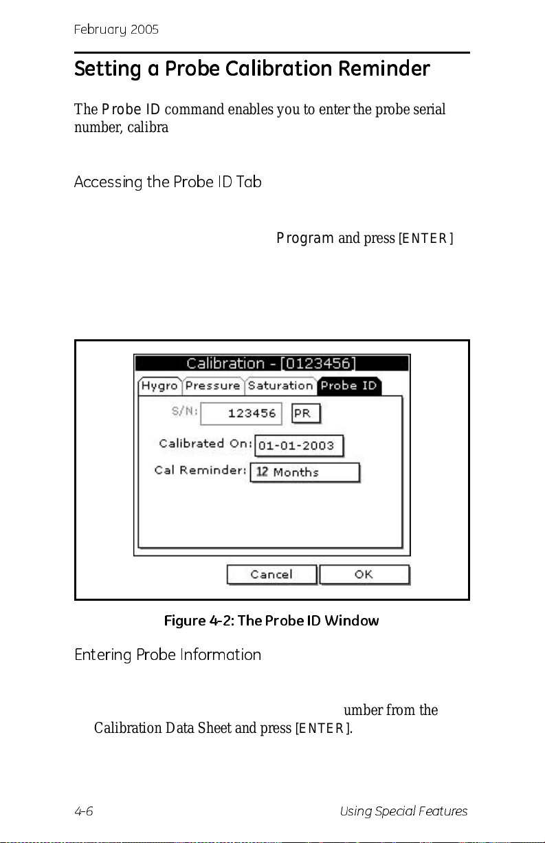
[ENTER]. A screen similar to Figure 4-2 appears.
Figure 4-2: T he Probe ID W i nd ow
[ENTER].
[ENTER].
Entering Probe Information
1. Use the arrow keys to scroll to S/N and press [ENTER].
2. Use the numer ic keys to ent er the serial num b er from the
Calibration Data Sheet and press
is also scribed on the hex nut of the moisture probe.
4-6 Using Special Features
[ENTER]. The serial number
Page 55
Febr uar y 20 0 5
Setting a Probe Calibration Reminder (cont.)
Entering Probe Information (cont.)
3. Use the arrow keys to scroll to the suf fix box and press
[ENTER] to open the drop-down list.
4. Use the arrow keys to scroll to the desire d suf fix and press
[ENTER].
5. Use the arrow keys to scroll to Calibrated On and press
[ENTER].
6. Use the numeric and arrow keys to enter the most recent
calibration date . When you have enter ed the desired month,
day and year, and press
[ENTER].
Note:
Refer to the calibratio n data sheet for the most recent
calibration date.
7. Use the arrow keys to move to Cal Reminder and press
[ENTER]. This prompt asks you to select a time period for the
next probe calibration. The PM880 will display a calibration
reminder for the probe determined from the last calibration
date. GE Infrastructure Sensing recommends recalibrating a
probe a minimum of once a year.
8. Use the arrow keys to move to the desired selection and press
[ENTER].
9. Press
[F3] (OK) and then [MENU].
The PM880 returns to taking measurement s.
What’s Next?
The calibration reminder is part of the site file; therefore, if you
are not planning on making any more changes to the site file you
should save the new changes. Refer to Saving a New Site File on
page 6-2.
Using Special Features 4-7
Page 56
February 2005
Using Automatic Calibration (Auto-Cal)
The PM880 automatically cali brate s the moisture and pressure
measurement circuitry (Auto-cal) at a user-selected interval.
Auto-cal compensates for any drift in the electronics. GE
Infrastruct ure Sensing recommends setting the Auto0cal inte rval
to 8 hours. Set a smaller interval to Auto-cal more frequently if
the meter is exposed to extreme temperatures or weather
conditions.
Note:
Use the steps below to enter an Auto-cal inte r val:
1. If the menu is not active, press
2. Use the arrow key to scro ll to Program and press
3. Use the arrow key to scro ll to System and press
If you are only using Moisture Image Series (MIS) probes
to measure moisture, the System Menu is not available.
[MENU].
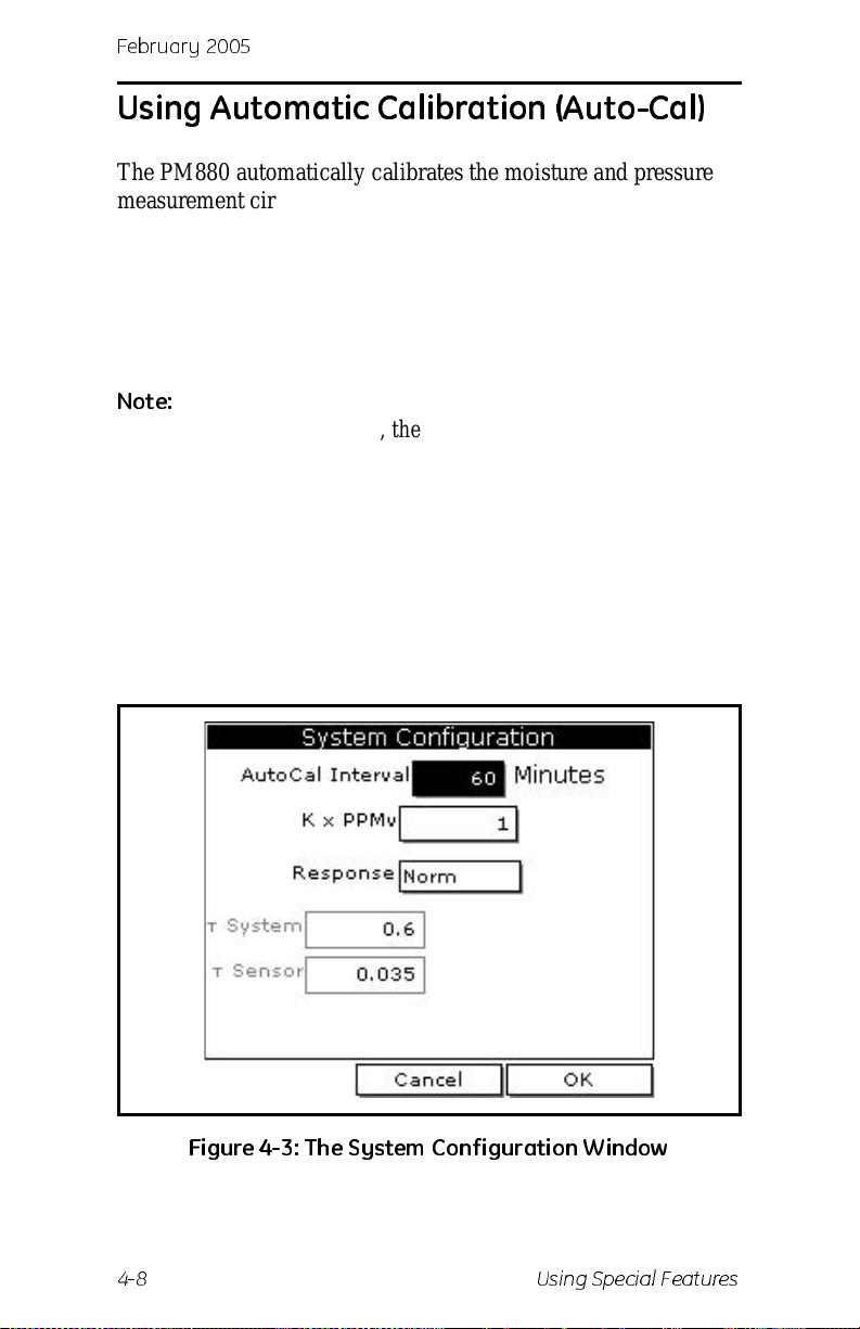
screen similar to Figure 4-3 below appears.
[ENTER].
[ENTER]. A
Figure 4-3: The System Configuration Window
4-8 Using Special Features
Page 57
Febr uar y 20 0 5
Using Automatic Calibration (Auto-Cal)
4. If necessary, use the arrow keys to move to the AutoCal
Interval text box.
5. Press
Note:
The next time Auto-cal occurs will depend on the length of the
time interva l that was sele ct ed. See the ex am p l e below.
EXAMPLE:
The PM880 establishes a fixed schedule , beginning at midnight,
using the interval spec ified to determine the times of subsequent
Auto-cals . If you en ter an 8 hour time i nter val , Au to-c al will
occur 3 times per day (1 day = 1440 minutes/480 minutes = 3).
The fixed schedule will be as follows:
If you set the 8 hour Auto-cal interval at 8:10 a.m. , the next Autocal will occur at 4:00 p.m. (excluding the Auto-cal performed
when first leaving System Confi guration window).
[ENTER] to open the text box. Use the numeric keys to
enter the desired value (in minutes) and press
GE Infrastructure Sensing recommends setting the
Auto0cal interval to 8 hours (480 minutes).
1.8:00 a.m.
2.4:00 p.m.
3.12:00 a.m. (midnight)
[ENTER].
What’s Next?
Do one of the following:
• Use the arrow keys to move to another text box and enter
additional data.
• T o exit and return to taking measurements, press [F3] (OK)
and then
Using Special Features 4-9
[MENU].
Page 58
February 2005
Entering Cons tants and User Fun ction s
The PM880 enables you to enter two types of constants, a user
constant and a saturation c onstant, as well as user-defined
functions and tables to manipula te data.
A user constant is a fixed value that is used to multiply the
moisture ppm value (K
calculate PPMw in non-aqueous liquids. If you do not know the
saturation constant of the liquid, contact GE Infrastructure
Sensing.
T o extend programming capability, user functions enable you to
program up to 8 mathematical equations. Additionally, the
PM880 also enables you to enter up to 6 tables of non-line ar or
empirical data to support user function equations.
This section consists of the following information:
• Entering a User Constant - see below.
• Entering a Saturation Constant - page 4-12
× PPMv). A saturation constant is used to
• Entering User Functions - page 4-14
• Setting Up User Tables - page 4-19
Entering a User Constant
Use the following steps to enter a user constant. The default
multiplier is 1.
1. If the menu is not active, press
2. Use the arrow key to scro ll to Program and press
3. Use the arrow key to scro ll to System and press
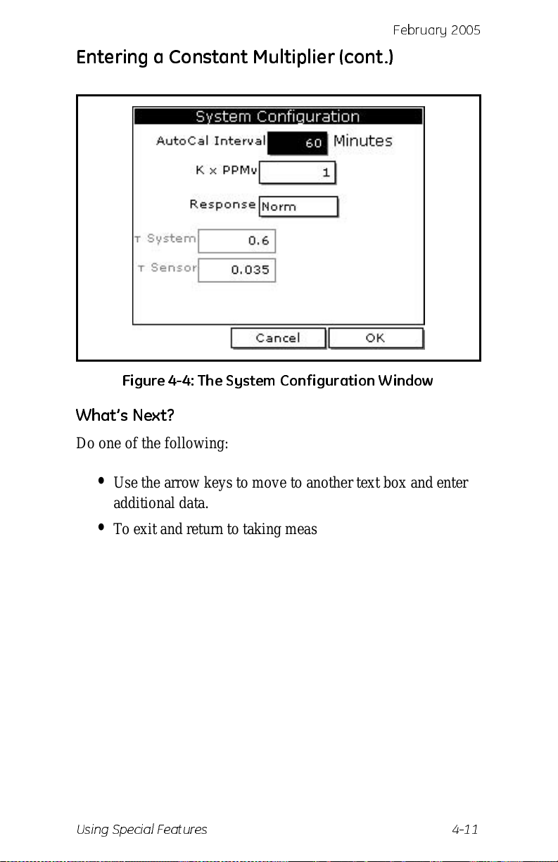
screen similar to Figure 4-4 on the next page appears.
4. Use the arrow keys to move to the K
[ENTER].
press
5. Use the numeric keys to enter the desired value and press
[ENTER].
4-10 Using Special Features
[MENU].
[ENTER].
[ENTER]. A
× PPMv text box and
Page 59
Entering a Constant Multiplier (cont.)
Figure 4-4: The System Configuration Window
What’s Next?
Febr uar y 20 0 5
Do one of the following:
• Use the arrow keys to move to another text box and enter
additional data.
• T o exit and return to taking measurements, press [F3] (OK)
and then
Using Special Features 4-11
[MENU].
Page 60
February 2005
Entering a Saturation Constant
The PM880 requires a saturation con stant in order to calculate
ppm
in non aqueous liquids. If you do not know the saturation
w
constants of the process liquid sample, contact GE Infrastructure
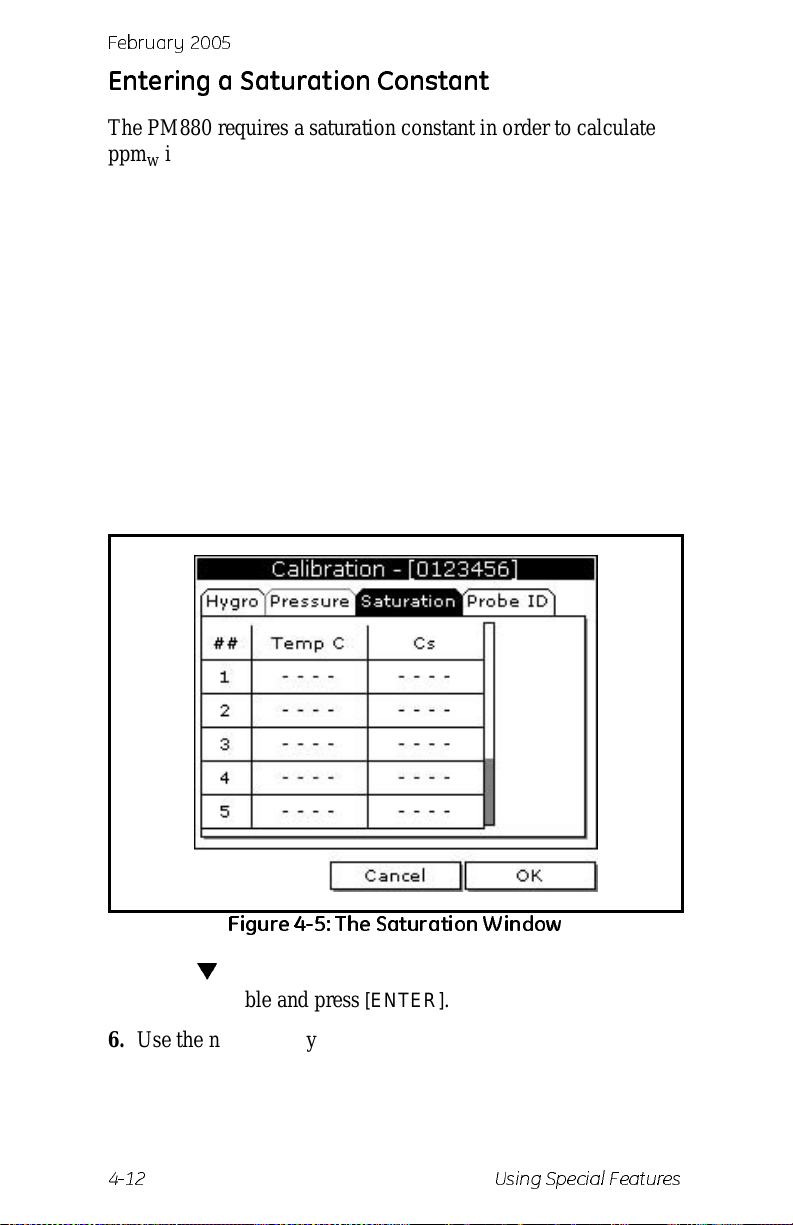
Sensing. To enter a saturation constant (Cs ), you must e nter 1 to 8
data points to repr esen t a cur ve of Cs (va lues) versus temper atur e.
To enter data for a saturation constant:
1. If the menu is not active, press
2. Use the arrow key to scro ll to Program and press
3. Use the arrow key to scro ll to Calibrate and press
[MENU].
[ENTER].
[ENTER].
4. Use the arrow key to scro ll to Saturation tab and press
[ENTER]. A screen similar to Figure 4-5 below appears.
Figure 4-5: The Saturation Window
5. Press [] to move the pointer to the Temp C box in the
saturation table and press
[ENTER].
6. Use the numeric keys to enter the desired temperature value
and press
Test Equipment Depot - 800.517.8431 - 99 Washington Street Melrose, MA 02176
4-12 Using Special Features
FAX 781.665.0780 - TestEquipmentDepot.com
[ENTER].
Page 61
Febr uar y 20 0 5
Entering a Saturation Constant (cont.)
7. The Cs text box is highlighted, press [ENTER]. Use the
numeric keys to enter the corresponding Cs value and press
[ENTER].
8. Repeat steps 6 and 7 un til you h ave ente red the valu es f or each
data point.
Note:
9. When you have completed entering values, press
To insert an additional data point, press [F1] (Insert).
To delete a data point, press
[F2] (Delete).
[F3] (Exit).
What’s Next?
Do one of the following:
• Use the arrow keys to scroll to another ta b and progr am
additional data (if available, depending on probe type).
• T o exit and return to taking measurements, press [F3] (OK)
and then
[MENU].
Using Special Features 4-13
Page 62
February 2005
Entering User Functions
User functions enable you to prog ram mathematical equations.
You can use any parameter in the meter to calculate a different
parameter. T o enter a user-defined equation:
Accessing the User Function Command
1. If the menu is not active, press [MENU].
2. Use the arrow key to scro ll to Program and press
3. Use the arrow key to scro ll to Us er F unctions and press
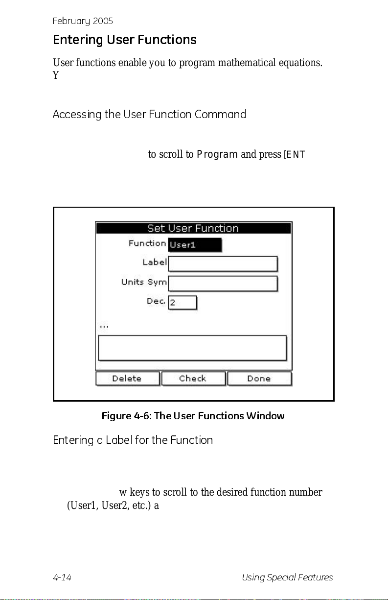
[ENTER]. A screen similar to Figure 4-6 below appears.
Figure 4-6: The User Functions Window
[ENTER].
Entering a Label for the Function
1. The Function box should be highlighted. Press [ENTER] to
open the drop-down menu.
2. Use the arrow keys to scroll to the desire d function number
(User1, User2, etc.) and press
4-14 Using Special Features
[ENTER].
Page 63
Febr uar y 20 0 5
Entering User Functions (cont.)
Entering a Label for the Function (cont.)
3. Use the arrow keys to move to the Label box and press
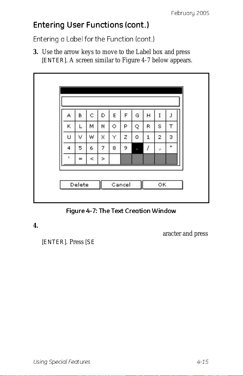
[ENTER]. A screen similar to Figure 4-7 below appears.
Figure 4-7: T h e Tex t C reati on W in d ow
4. Press [F1] (Delete) to delete any unwan ted lette rs or nu mbers.
Use the arrow keys to scroll to the desired character and press
[ENTER]. Press [SEL] to view addit iona l character selections
and symbols for creating a label for the function.
5. Repeat this procedure until you have created the desired units
symbol for the function of up to thirt y-two characters.
6. When you have finished, press
Using Special Features 4-15
[F3] (OK).
Page 64
February 2005
Entering User Functions (cont.)
Entering the Units
The steps below describe how to create a units symbol (e.g.
degrees C). This la bel will a ppear on t he screen wh en you displa y
the user functi on me as urement.
1. Use the arrow keys to move to the Units Sym box and press
[ENTER]. The text creation screen appears again.
2. Press
[SEL] to view the three scr eens with the available
characters and symbols for creating the symbol for the units.
3. Use the arrow keys to scroll to the desired character and press
[ENTER]. Press [F1] (Delete) to delete any unwanted letters or
numbers. Press
[SEL] to view addit ional character sel ecti o ns
and symbols for creating a label for the function.
4. Repeat this procedure until you have created the desired label
for the function of up to thirty-two characters.
5. When you have finished, press
[F3] (OK).
Selecting Decimal Digits
1. Use the arrow ke ys to m ove to t he Dec box a nd press [ENTER]
to open the drop-down menu.
2. Use the arrow keys to scroll to the desired value (0-4) and
press
[ENTER]. This value refers to the number of digits to the
right of the decimal point.
Entering an Equation
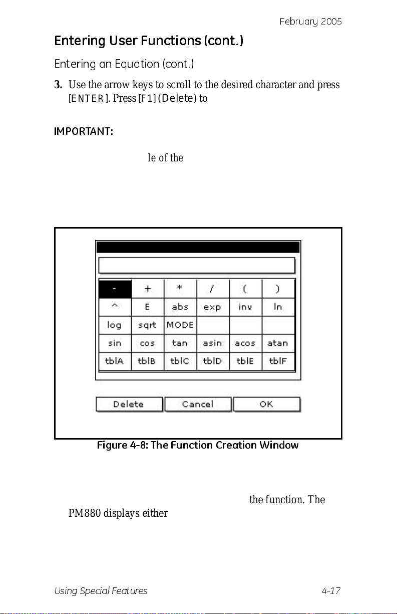
1. Use the arrow keys to move to the blank box at the bottom of
the screen and press
on the next page appears.
[ENTER]. A screen similar to Figure 4-8
2. Press
[SEL] to view additiona l characters, symbols and
functions for creat ing an equa tion.
4-16 Using Special Features
Page 65
Febr uar y 20 0 5
Entering User Functions (cont.)
Entering an Equation (cont.)
3. Use the arrow keys to scroll to the desired character and press
[ENTER]. Press [F1] (Delete) to delete any unwanted letters or
numbers.
IMPORTANT:
To enter a measurement (dew point , temperat ure,
etc.) into the equation, click on MODE in the
middle of the thir d row. The Select Measurement
window appears. Select the desired
measurements, press
units and pr ess
[SEL], select the de sired
[F3] (OK).
Figure 4- 8: Th e Fun ct ion Creat ion W i n dow
4. When you have finished entering the equation, press [F3]
(OK).
5. Press
[F2] (Check) to test the validity of the function. The
PM880 displays either “OK” or a message such as “Syntax
Error.”
Using Special Features 4-17
Page 66
February 2005
Entering User Functions (cont.)
Entering an Equation (cont.)
6. Do one of the following:
• T o edit the equation, press [ENTER].
• To delete the equation, press [F1] (Delete).
• To confirm the equation and return taking measurements,
press
[F3] (Done) and then press [MENU].
Note:
To display the user function on the screen, r efer to
Displaying Measurement s on page 1-15. In the Select
Measurement window, choose Userfunction and then the
units you entered above.
4-18 Using Special Features
Page 67
Febr uar y 20 0 5
Setting Up User Tables
To support user-defined functions, the PM880 can hold up to 6
tables of non-linea r or empirical data. Users can enter up to 21
X-Y pairs in each table . The us er functions can supp ly an X valu e
with Table (X). The meter then interpola tes the Y value for a
given X, and substitutes it for Table (X) in the function. (The
results are extrap olated if the X value exceeds the bounds of the
table.) To set up a user table:
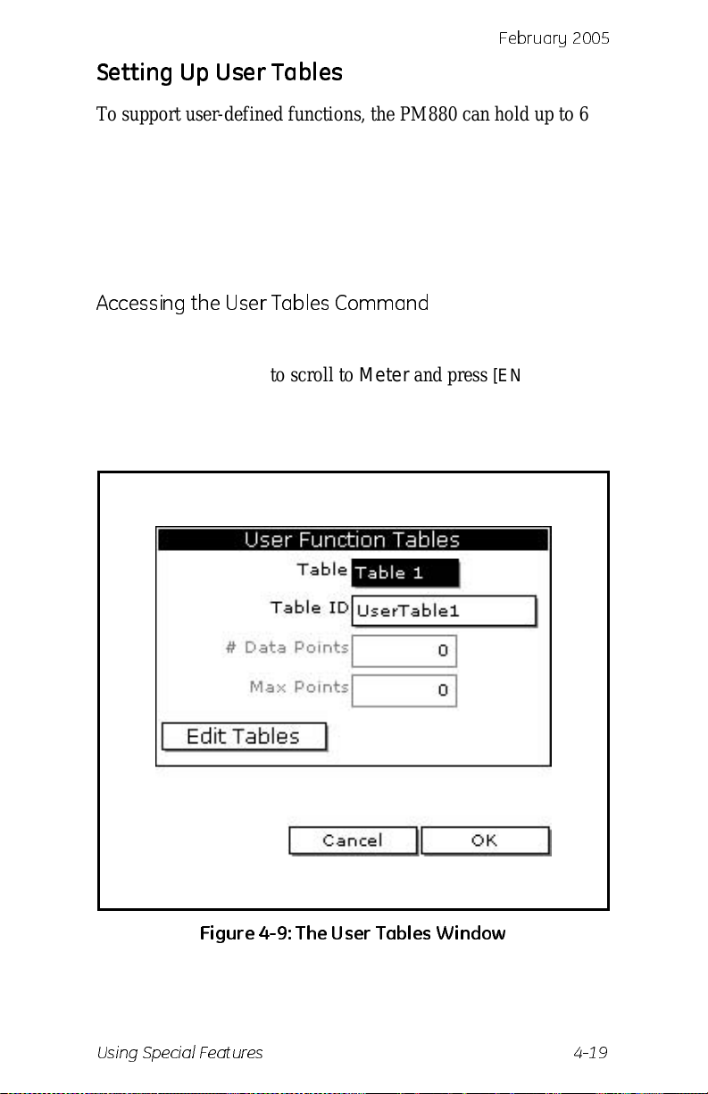
Accessing the User Tables Command
1. If the menu is not active, press [MENU].
2. Use the arrow key to scro ll to Meter and press
3. Use the arrow key to scro ll to Us er Tables and press
[ENTER]. A screen similar to Figure 4-9 below appears.
[ENTER].
Figure 4-9: The User Tables Window
Using Special Features 4-19
Page 68
February 2005
Setting Up User Tables (cont .)
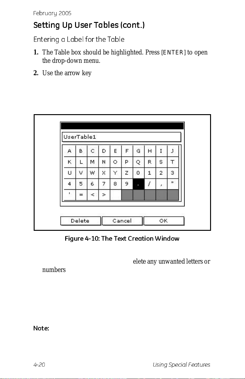
Entering a Label for the Table
1. The Table box should be highlighted. Press [ENTER] to open
the drop-down menu.
2. Use the arrow keys to scroll to the desire d tabl e number and
press
[ENTER].
3. Use the arrow keys to move to the Table ID box and press
[ENTER]. A screen similar to Figure 4-10 below appears.
Figure 4-10: Th e Tex t Creat ion W in d ow
4. Use the arrow keys to scroll to the desired character and press
[ENTER]. Press [F1] (Delete) to delete any unwanted letters or
numbers. Press
[SEL] to view th e th r ee scr e ens with the
available characters and symbols for creating a label for the
table.
5. Repeat this procedure until you have created the desired label
for the table of up to thirty-two characters.
6. When you have finished, press
Note:
It is not necessary to enter the “#Data Points” or “Max
[F3] (OK).
Points” text boxes. The meter automatically enters this
data.
4-20 Using Special Features
Page 69
Febr uar y 20 0 5
Setting Up User Tables (cont .)
Editing the User Table
1. Use the arrow keys to move to Edit Tables box and press
[ENTER].
2. Press [
] to move the pointer to the 1/Table ID column.
3. Press
4. Press [
[ENTER] to open the text box. Use the numeric keys to
enter the desired value and press
] to move to the next text box, and press [ENTER].
[ENTER].
Use the numeric keys to enter the corresponding value and
[ENTER].
press
5. Use the arrow keys to scroll to additional data points and
repeat steps 2, 3 and 4 until you have entered the value s for
each data point.
6. When you have completed entering values, press
[F3] (OK).
7. T o confirm the table and return taking meas urements, press
[F3] (OK) and then press [MENU].
Using Special Features 4-21
Page 70
February 2005
Using Comput er Enh an ced Res ponse
Computer Enhanced Response (CER) uses a dynamic mois ture
calibration tec hnique to extrapolate the moisture le vel to the end
point when making measurements in abru pt “dry down”
conditions. The system response time depends on the relative
change in dew point. For a change from ambient moisture levels
to trace levels, the unit can respond in 3 to 5 minutes.
The accuracy of enhanced response is
sensor would have read if it were allowed to rea ch equilibrium
with the gas. To ensure that CER is as accurate as possible, your
application should:
o
± 2
C of the reading the
• have a reasonably constant f inal dew point and flow rate.
• have a minimum flow rate of one standard cubic foot per
hour (SCFH).
• operate at atmospheric pressure (0 psig).
• have an actual moist ure co n ten t equ al to or wetter than a
dew/frost point of
• MIS Probe: -8 5
• M Series and TF Series Probe: -110
Use the steps below to activate comput er enh anced response:
Accessing the Response Command
1. If the menu is not active, press [MENU].
o
C
o
C
2. Use the arrow key to scro ll to Program and press
3. Use the arrow key to scro ll to System and press
screen similar to Figure 4-11 on the next page appears.
Test Equipment Depot - 800.517.8431 - 99 Washington Street Melrose, MA 02176
FAX 781.665.0780 - TestEquipmentDepot.com
4-22 Using Special Features
[ENTER].
[ENTER]. A
Page 71
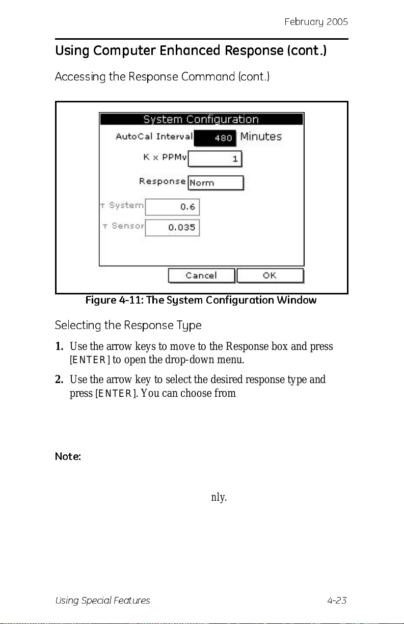
Febr uar y 20 0 5
Using Computer Enhanced Response (cont.)
Accessing the Response Command (cont.)
Figure 4-11: The System Configuration Window
Selecting the Response Type
1. Use the arrow keys to move to the Response box and press
[ENTER] to open the drop-down menu.
2. Use the arrow key to sele ct the d es ired res pons e ty pe and
press
[ENTER]. You can choose from the following:
• NORM - no computer enhanced response
• CER - enable computer enhanced response
Note:
3. To return to taking measurements, press
Using Special Features 4-23
The PM880 has an additional option calle d Derivative
Fast Response (DEF). The T System and T Sensor options
are only active when DEF is selected. This option is
available in Servi ce Mode only . Consult GE Inf rastructur e
Sensing
[F3] (OK) and then
press
[MENU].
Page 72
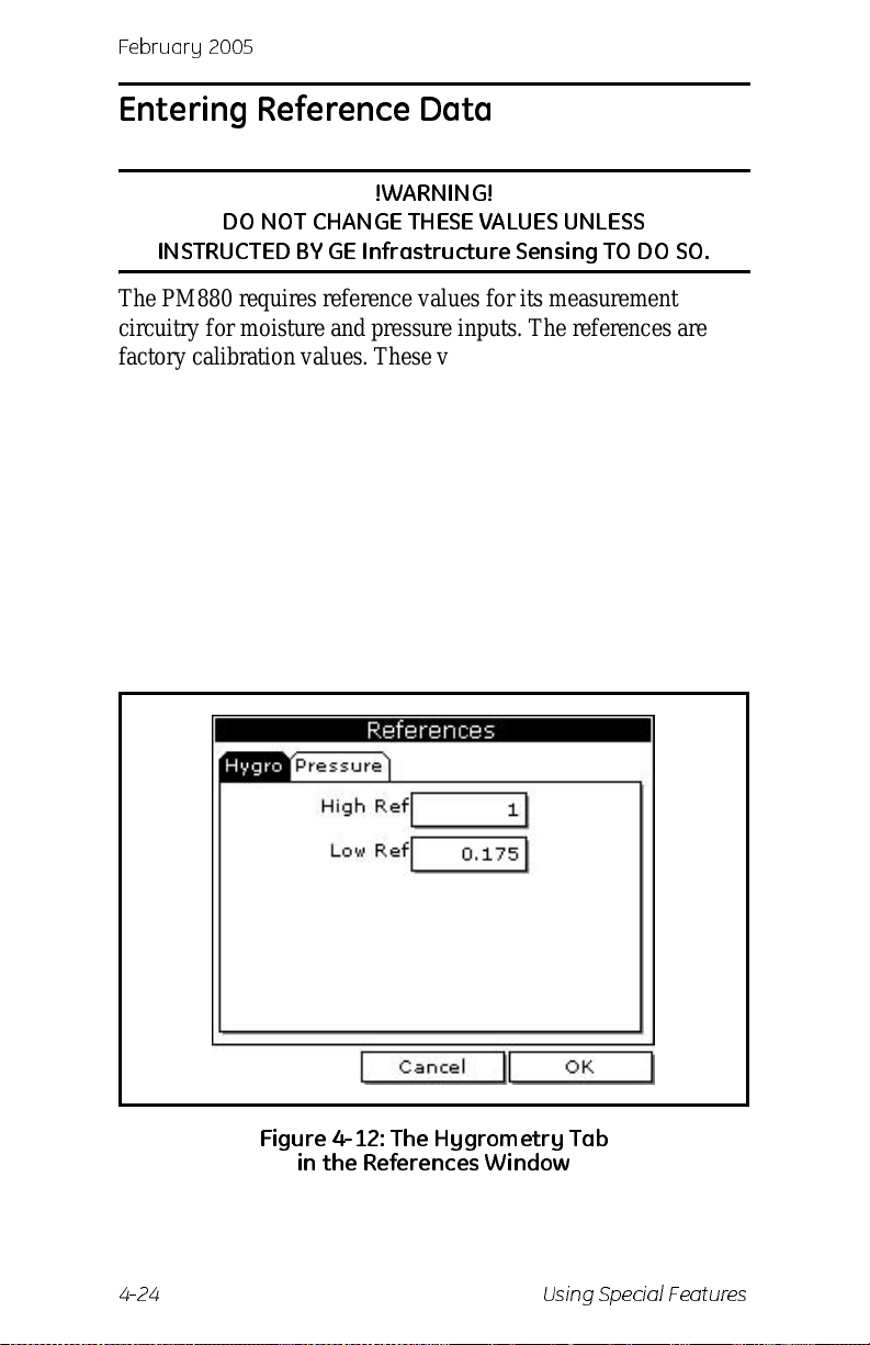
February 2005
Entering Reference Data
!WARNING!
DO NOT CH AN GE T HESE VALUES UNL ESS
INSTRUCTED BY GE Infrastructure Sensing TO DO SO.
The PM880 requires reference values for its measurement
circuitry for moistur e and pressure inputs. The references are
factory cal ibration values. These values can be found on the label
located inside the batt ery co mpartment.
If instructed by GE I nfras truct ure Sensing to c hange the se val ues,
refer to the steps follo w s.
1. If the menu is not active, press
2. Use the arrow keys to scroll to Service and press
3. Use the arrow keys to scroll to References and press
[ENTER]. The screen appears similar to Figure 4-12 below.
[MENU].
[ENTER].
Figure 4- 12: T he Hy grom et ry Tab
in th e Re fe ren ces W i n dow
4-24 Using Special Features
Page 73
Febr uar y 20 0 5
Entering Reference Data (cont.)
4. Use the arrow keys to move to the desired tab and press
[ENTER].
5. Use the arrow keys to move to High Ref and press
open the text box.
6. Use the numer ic keys to ent er the valu e reco r ded on the b ack
of the PM880 and press
7. Repeat steps 5 and 6 for the low ref ere nc e va lue .
[ENTER].
[ENTER] to
What’s Next?
Do one of the following:
• T o exit and return to taking measurement s, pr ess [F3] and
then
[MENU].
• If you need to cha nge value s, use t he arrow ke ys to move to
the other tab and return to step 5 above.
Using Special Features 4-25
Page 74
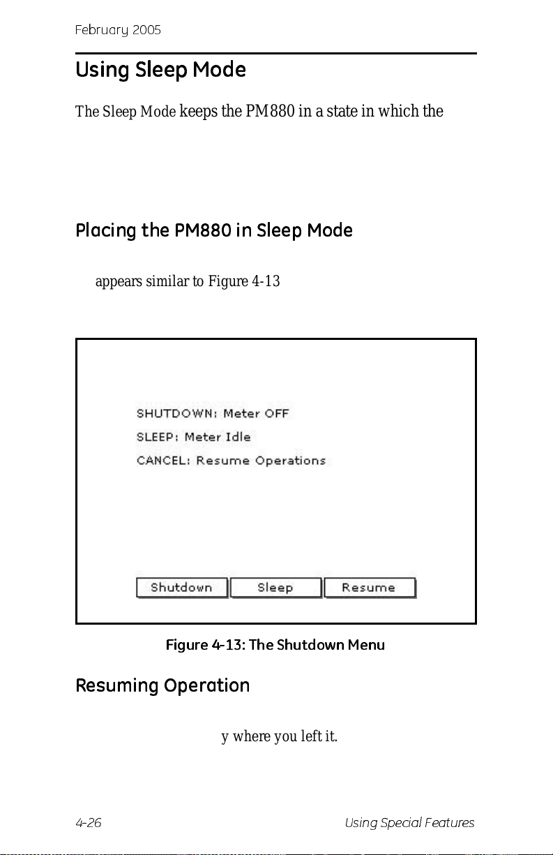
February 2005
Using Sleep Mode
The Sleep Mode keeps the PM880 in a state in which the unit
appears to be off. During Sleep Mode the unit is idle and
consumes less power. When you want to use the unit again, it
comes out of Sleep Mode quickly, performs an auto-cal and is
restored exactly as you left it.
Placing the PM880 in Sleep Mode
1. Press the red power key for 3 seconds. The screen now
appears similar to Figure 4-13 below.
2. Press
[F2] to place the PM880 in Sleep Mode.
Figure 4-13: The Shutdown Menu
Resuming Operation
T ap the red power key. The PM880 powers on, performs an autocal and returns to ex ac tly where you left it.
4-26 Using Special Features
Page 75
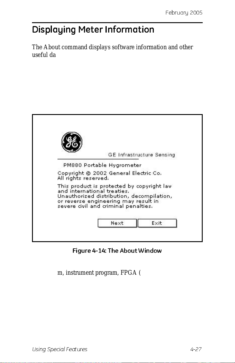
Febr uar y 20 0 5
Displaying Meter Inf ormatio n
The About command displays software information and other
useful data specific to your meter. To display meter information:
1. If the menu is not active, press
2. Use the arrow key to scro ll to Site and press
[MENU].
[ENTER].
3. Use the arrow key to scro ll to About and press
screen similar to Figure 4-14 below appears.
[ENTER]. A
Figure 4- 14: T he Ab ou t W i n dow
4. Press [F2] (Next) to list additional data such as the boot
program, instrument program, FPGA (timing) program,
language, help version, serial number and PCI number.
5. Press
[F3] (Exit) and then press [MENU].
The PM880 returns to taking measurement s.
Using Special Features 4-27
Page 76
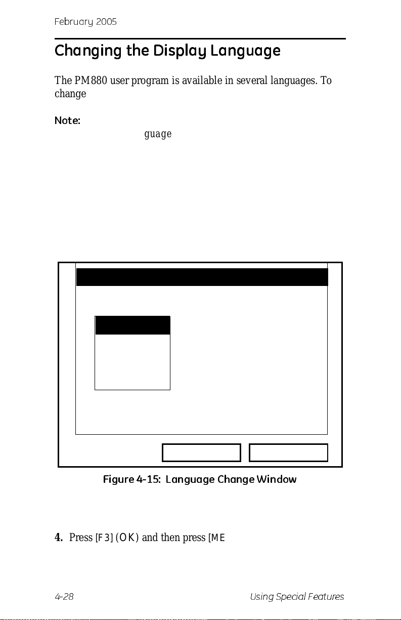
February 2005
Changing the Display Language
The PM880 user program is available in several languages. To
change the language:
Note:
The PM880 defaults to US English. Howeve r, one or more
alternate languages can be installed at any time. Consult
your GE Infrastructure Sensing rep resentativ e or
www.gesensing. com for available languages.
1. If the menu is not active, press
[MENU].
2. Use the arrow key to scro ll to Meter and press
Use the arrow key to scro ll to Language and press
screen similar to Figure 4-15 below appears.
Change Language
Select a D ef ault Language
English
Espanol
[ENTER].
[ENTER]. A
Cancel OK
Figure 4-15: Language Change Window
3. Use the arrow keys to scroll to the desired language and press
[ENTER].
4. Press
[F3] (OK) and then press [MENU].
The meter restarts in the desired language.
4-28 Using Special Features
Page 77

Febr uar y 20 0 5
Using On-Line Help
The PM880 offers on-lin e help scre ens that contain descriptions
and instructions for va rious topics. You can access on-line help at
anytime by press the [?] key . The on-line hel p screen that appear s
depends on what the meter is doing at the time the [?] key is
pushed. While:
• taking measurements - the on-line help screen displays a
table of contents.
• in the user program - the on-line help screen displays the
help screen relevant to the program menu.
Use the function keys at the bottom of the screen to navigate
through on-line help.
Using Special Features 4-29
Page 78
Febr uar y 20 0 5
Chapter 5
Logging Data
Data logging is one of the PM880’s most powerful and flexible
features. The mete r enables you t o cho ose up to 12 measur ements
to log. Logs can run one at a time or simultaneously. Error and
circular logs are also available. The logged data is internally
stored in battery-b acked-up memory.
A fixed amount of memory is assigned to store logs. The
frequency of the time interval, the length of the log run, and the
number of logs affect the amount of memory req uired for a
particular log. For example, a 2 hour log that records every 5
seconds will use up more memory than a 2 hour log that records
every 5 minutes .
The PM880 also has various tools to enable you to do the
following:
• setting up a new log - page 5-2
• pausing a log - page 5-6
• starting and restarting a log - page 5-7
• ending a log - page 5-8
• viewing all logs - page 5-9
• viewing log setup details - page 5-10
• viewing logged data in graph or spreadsheet format - page
5-12
The PM880 has additional logging capabilities. For more details
on these functions refe r to Chapter 6, Managing Files and
Chapter 7, Using the PM880 with a PC and Printer.
Logging Data 5-1
Page 79
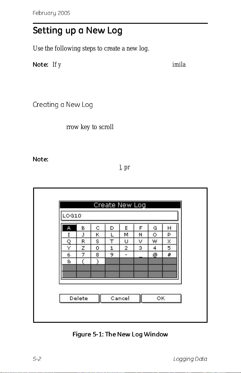
February 2005
Setting up a New Lo g
Use the following steps to create a new log.
Note:
If you need to create another log file that is similar to a
log you have alre ady created, yo u can save time by
copying the e xisting log and editing it. Refer to Copying a
Log on page 6-9.
Creating a New Log
1. If the menu is not active, press [MENU].
2. Use the arrow key to scro ll to Logging and press
3. Use the arrow key to scroll t o New Log a nd press
screen similar to Figure 5-1 below appears.
Note:
You can also cre ate a new log by scrolling to Log
Manager, press
press
[ENTER], scroll to New and press [ENTER].
[ENTER], press [MENU], scroll to File,
[ENTER].
[ENTER]. A
Figure 5- 1: Th e Ne w Log W i n dow
5-2 Logging Data
Page 80
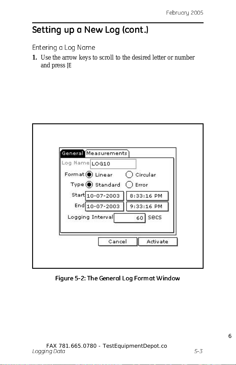
Febr uar y 20 0 5
Setting up a New Lo g (con t.)
Entering a Log Name
1. Use the arrow keys to scroll to the desire d letter or number
and press
unwanted letters or numbers.
2. Repeat this procedure until you have created the desired log
name of up to eight characters.
[ENTER]. Press [F1] (Delete) to delete any
3. When you have finished, press
Figure 5-2 below appears.
[F3] (OK). A screen similar to
Figure 5-2: T h e General Log Format W in d ow
Test Equipment Depot - 800.517.8431 - 99 Washington Street Melrose, MA 02176
FAX 781.665.0780 - TestEquipmentDepot.com
Logging Data 5-3
Page 81
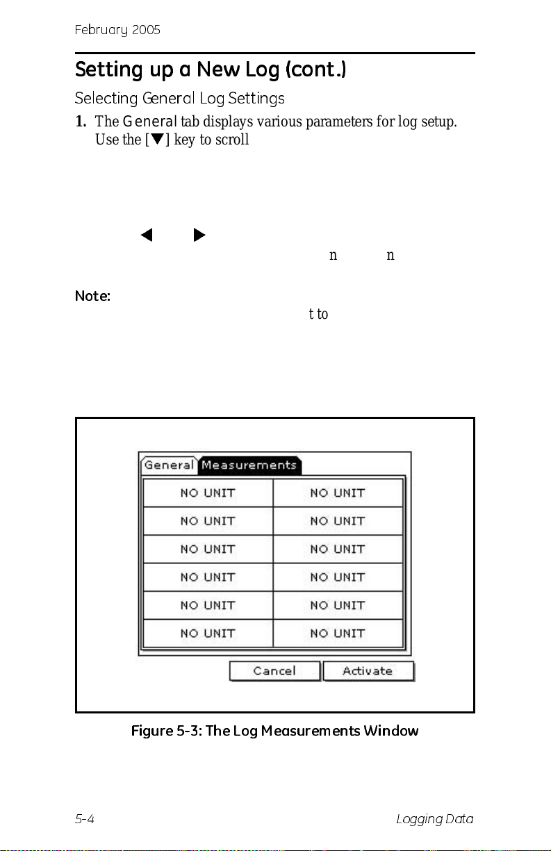
February 2005
Setting up a New Lo g (con t.)
Selecting General Log Settings
1. The General tab displays various parameters for log setup.
Use the [
• Use the arrow ke ys to make a selection and press [ENTER].
• T o e dit t ext boxes, scr oll to the box and pr ess [ENTER]. Use
Note:
2. Use the arrow keys to move to the Measurements tab and
press
] key to scroll to Format and do the following:
Use the same procedure for Type.
] and [] keys to scroll to the number to change and
the [
use the numeric keys to change the number and press
[ENTER].
If you choose to run a circ ular log, you will need to enter
the number of rec ords you want to log instead of an end
date and time.
[ENTER]. A screen similar to Figure 5-3 below appears.
Figure 5-3: The Log Measurements Window
5-4 Logging Data
Page 82
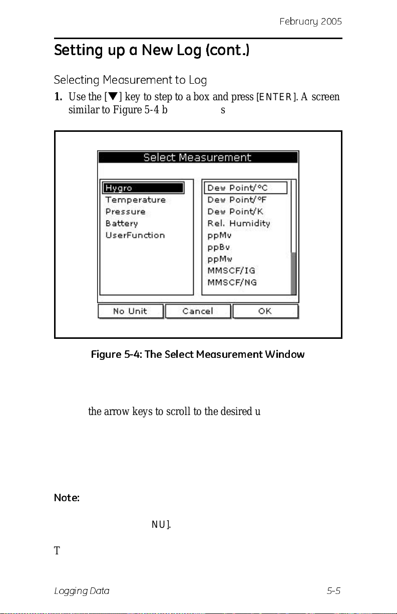
Febr uar y 20 0 5
Setting up a New Lo g (con t.)
Selecting Measurement to Log
1. Use the [] key to step to a box and press [ENTER]. A screen
similar to Figure 5-4 below appears.
Figure 5-4: T he Sel e ct M easu rem e nt W i nd ow
2. Use the arrow keys to scroll to the desired measurement type
and press
3. Use the arrow ke ys to scroll to the desired units a nd press
[SEL].
[F3]
(OK).
4. Repeat steps 1 through 3 for up to 12 different parameters.
5. When you have f inished, press
[F3] (Activate) to start the log.
The log will begin at the specifie d date and ti me.
Note:
If you cre ated the log from within the Log Manager, the
meter returns to the Log Manager, press
then pre ss
[MENU].
[F3] (Exit) and
The PM880 returns to taking measurement s. A Pencil icon
appears in the bottom right- hand side of the screen.
Logging Data 5-5
Page 83
February 2005
Pausing a Log
The PM880 has two commands to p ause logs: Pause and Pause
All Lo gs . The PM880 can only pause logs that are currently
running.
Note:
Use the steps below to pause one or more logs:
The PM880 als o has an End command that enables you to
stop the log permanently. See Ending a Log on page 5-8.
Accessing the Log Manager
1. If the menu is not active, press [MENU].
2. Use the arrow key to scro ll to Logging and press
3. Use the arrow key to scro ll to Lo g M anager and press
[ENTER].
[ENTER].
Selecting a Log File
1. Use the arrow key to scroll to the desired log.
Note:
2. Press
3. Use the arrow key to scro ll to Log and press
4. Use the arrow key to scro ll to Pause or Pa us e All Logs and
The list of log files in the Log Manager can be listed
chronologically or alphabetically. Refer to Sorting Files
in the Site/Drive/Log Manag er on page 6-15.
[MENU].
[ENTER].
press
[ENTER].
The PM880 returns to the Log Manager, which displays the
selected log as Paused.
What’s Next?
Do one of the following:
• T o pause another log, repeat the above steps.
• To return to taking measurements, press [F3] (Exit) and
then press
5-6 Logging Data
[MENU].
Page 84
Febr uar y 20 0 5
Starting or Restarting a Log
The Start and Start All Logs commands enabl e y ou to restar t a
paused log or start a pending log. You cannot restart a log that is
completed or ended using the End command.
Use the following steps to star t or restart one or more logs:
Accessing the Log Manager
1. If the menu is not active, press [MENU].
2. Use the arrow key to scro ll to Logging and press
3. Use the arrow key to scro ll to Lo g M anager and press
[ENTER].
[ENTER].
Selecting a Log File
1. Use the arrow key to scroll to the desired log.
Note:
2. Press
3. Use the arrow key to scro ll to Log and press
4. Use the arrow key to scro ll to Start or Start All Logs and
The PM880 returns to the Log Manager, which displays the
selected log as Running or Pending.
The list of log files in the Log Manager can be listed
chronologically or alphabetically. Refer to Sorting Files
in the Site/Drive/Log Manag er on page 6-15.
[MENU].
[ENTER].
press
[ENTER].
What’s Next?
Do one of the following:
• T o start or restart another log, repeat the above steps.
• To return to taking measurements, press [F3] (Exit) and
then press
Logging Data 5-7
[MENU].
Page 85
February 2005
Ending a Log
The End and End All Logs commands enables you to stop a log
that is cu rrently running or pending. Once you end a log it cannot
be restarted.
Note:
Use the following steps to star t or restart one or more logs:
The PM880 also has an Pause command that enable s
you to stop the log temporarily. See Pausing a Log on
page 5-6.
Accessing the Log Manager
1. If the menu is not active, press [MENU].
2. Use the arrow key to scro ll to Logging and press
3. Use the arrow key to scro ll to Lo g M anager and press
[ENTER].
[ENTER].
Selecting a Log File
1. Use the arrow key to scroll to the desired log.
Note:
2. Press
3. Use the arrow key to scro ll to Log and press
4. Use the arrow ke y to scroll to End or End All Logs and press
The list of log files in the Log Manager can be listed
chronologically or alphabetically. Refer to Sorting Files
in the Site/Drive/Log Manag er on page 6-15.
[MENU].
[ENTER].
[ENTER].
The PM880 returns to the Log Manager, which displays the
selected log as Finished.
What’s Next?
Do one of the following:
• T o end another log, repeat the above steps.
• To return to taking measurements, press [F3] (Exit) and
then press
5-8 Logging Data
[MENU].
Page 86
Febr uar y 20 0 5
Viewing All Logs
Logs are associated with the site in use at the time the log is
created (or run). By default, the Log Manager only displays the
logs created with the site file that is currently running. The Log
Manager has a command that enables you to view all existing
logs regardless of the current site file.
To view all existing logs (finished or pending):
Accessing the Log Manager
1. If the menu is not active, press [MENU].
2. Use the arrow key to scro ll to Logging and press
[ENTER].
3. Use the arrow key to scro ll to Lo g M anager and press
[ENTER].
4. Press
5. Use the arrow keys to scroll to Log and press
[MENU].
[ENTER].
6. Use the arrow keys to scroll to View All Sites and press
[ENTER].
7. To return to taking measurements, press
press
[MENU].
[F3] (Exit) and then
Logging Data 5-9
Page 87
February 2005
Viewing Log Setup De tails
The PM880 enables you to view more than the log details shown
in Log Manager . The Details command enables you to see th e log
status, date and time, length, interval, records types of
measurements logged and service information.
Accessing the Log Manager
1. If the menu is not active, press [MENU].
2. Use the arrow key to scro ll to Logging and press
3. Use the arrow key to scro ll to Lo g M anager and press
[ENTER].
[ENTER].
Selecting a Log
1. Use the arrow key to scroll to the desired log. Logs are
associated with the site file in use at the time the log is cre ated
or run. If you do not see the desired log in the list, refer to
Viewing All Logs on page 5-9 to display all the existing logs.
Note:
2. Press
3. Use the arrow key to scro ll to View and press
4. Use the arrow key to scro ll to Details and press
5. When you are done viewing the log details, press
The list of log files in the Log Manager can be listed
chronologically or alphabetically. Refer to Sorting Files
in the Site/Drive/Log Manag er on page 6-15.
[MENU].
[ENTER].
[ENTER]. A
screen similar to Figure 5-5 on the following page appear s.
[F3] (Exit).
What’s Next?
Do one of the following:
• T o vie w the de tail s of a nother log, pre ss [ESC] and retu rn t o
Selecting a Log above.
• T o exi t and retur n to taki ng measurem ents, pre ss [F3] (Exit)
and then press
5-10 Logging Data
[MENU].
Page 88
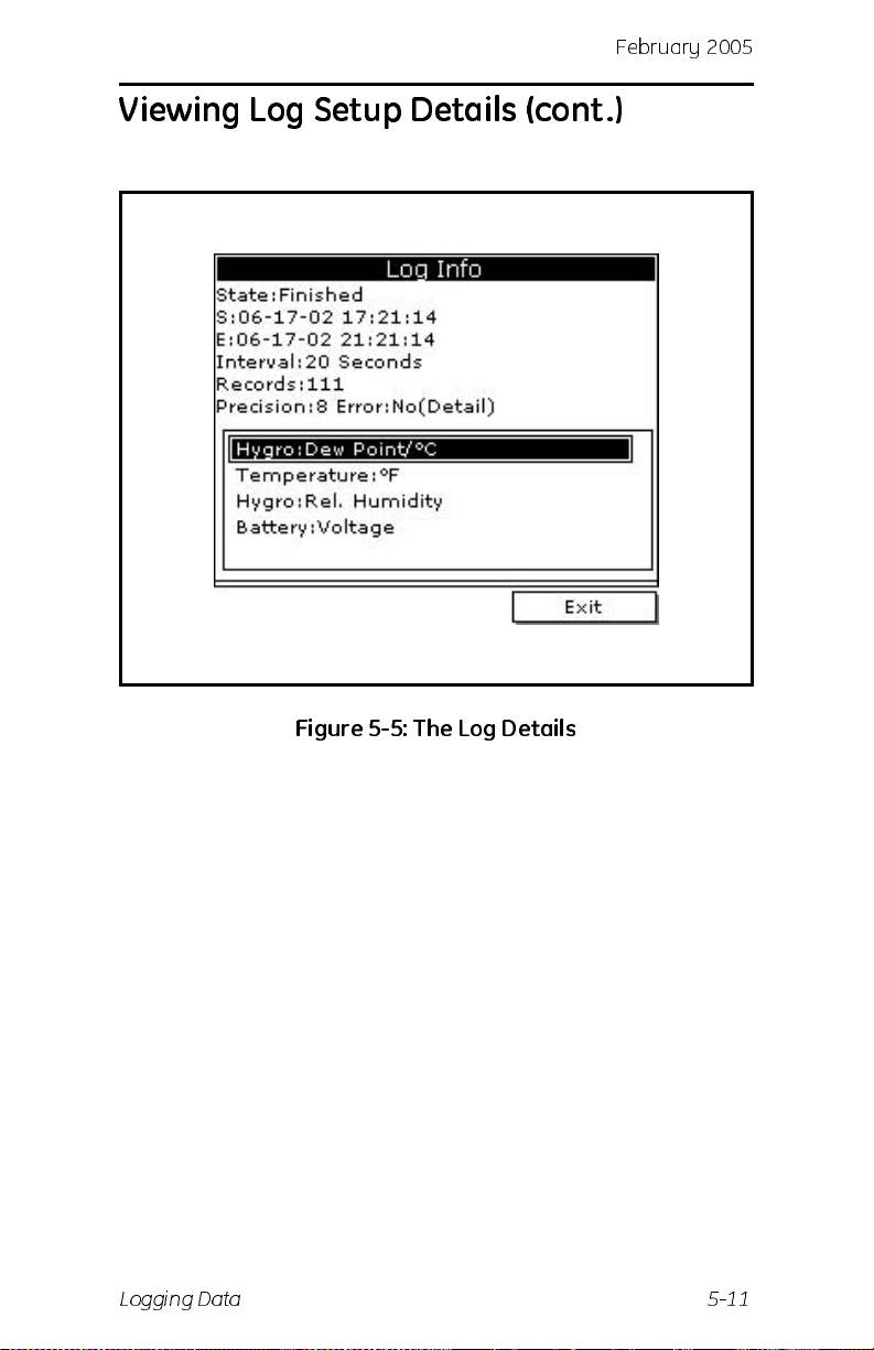
Viewing Log Setup Details (cont.)
Febr uar y 20 0 5
Figure 5-5: T he Log De tai ls
Logging Data 5-11
Page 89
February 2005
Displaying Logged Data
The PM880 enables you to view logged data in a graph or
spreadsheet format. Graphs and spreadsheets are setup in the Log
Manager. Use the steps below to access the Log Manager and
view logged data.
Accessing the Log Manager
1. If the menu is not active, press [MENU].
2. Use the arrow key to scro ll to Logging and press
3. Use the arrow key to scro ll to Lo g M anager and press
[ENTER].
4. T o view logged data in:
[ENTER].
• graph format, refer to Using the Graph Format below .
• spreadshee t format, refer to Using the Spreadsheet Format
on page 5-16.
Using the Graph Format
Selecting a Log
1. Use the arrow key to scroll to the desired log. Logs are
associated with the site file in use at the time the log is cre ated
or run. If you do not see the desired log in the list, refer to
Viewing All Logs on page 5-9 in the Log Manager to display
all the existing logs.
Note:
The list of log files in the Log Manager can be listed
chronologically or alphabetically. Refer to Sorting Files
in the Site/Drive/Log Manag er on page 6-15.
2. Press
3. Use the arrow key to scro ll to View and press
4. Use the arrow key to scro ll to Graph and press
5-12 Logging Data
[MENU].
[ENTER].
[ENTER].
Page 90
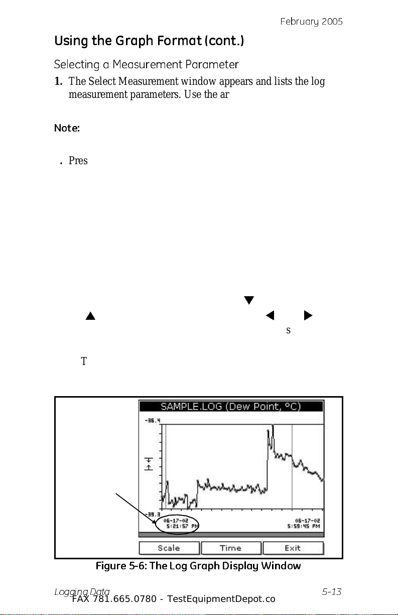
Febr uar y 20 0 5
Using the Graph Format (cont.)
Selecting a Measurement Parameter
1. The Select Measurement window appear s and lists the log
measurement parameters. Use the arrow keys to select the
measurement parameter to graph.
Note:
2. Press
3. Do one of the following:
The above step will not appear if the log consists of one
measure ment type. Skip to step 3.
[F3], View. A screen simil ar to Figure 5-6 below
appears.
• To adjust the graph scale, press [F1] (Scale) and go to page
5-14.
• To adjust the time scal e, pre ss [F2] (Time) and go to
page 5-15.
• To view the next measu rem en t in the l o g, pres s [SEL].
• To zoom in and out by 200%, press [
] to zoom out. when zoomed, use the [] and [] keys
[
to scroll through the graph . The scr een displays the range
when zoomed. See Figure 5-6 below.
] to zoom in and
• T o exi t and retur n to taki ng measurem ents, press [F3] (Exit)
twice and then press
[MENU].
Displays range
when zoomed
Figure 5-6: T he Log Graph Di spl ay W i nd ow
Test Equipment Depot - 800.517.8431 - 99 Washington Street Melrose, MA 02176
Logging Data 5-13
FAX 781.665.0780 - TestEquipmentDepot.com
Page 91
February 2005
Using the Graph Format (cont.)
Adjusting the Graph Scale
1. The Y-Axis window appears. Use the arrow keys to scroll to
one of the following and press
[ENTER]:
• Max - the graph extends to highest logged value.
• Range - the graph extends from the lowest to the highest
logged value.
• Set - the graph extends between a specified minimum and
maximum v alu e.
2. Do one of the following:
• If you selected Max or Range, proceed to step 6.
• If you selected Set, proceed to the next step.
3. Use the arrow keys to scroll to the Minimum text box and
press
[ENTER].
4. Use the numeric keys to enter the desired value and press
[ENTER].
5. Repeat steps 3 and 4 to enter the Maximum value.
6. When you have finished, press
graph.
[F3] (OK) to exit and view the
What’s Next?
Do one of the following:
• T o return to the Log Manager and view another log, press
[F3] (Exit) and then p ress [MENU]. Return to Using the
Graph Format on page 5-12.
• T o view logs using the spreadsheet for mat, pr ess [F3]
(Exit), then pr ess
Spreadsheet Format on page 5-16.
[MENU] and proceed to Using the
• T o exi t and retur n to taki ng measurem ents, pre ss [F3] (Exit)
twice and then press
5-14 Logging Data
[MENU].
Page 92
Febr uar y 20 0 5
Using the Graph Format (cont.)
Adjusting the Time Scale
1. The Enter Time window appears. Use the arrow keys to scr oll
to the desired text box. Press
2. Use the numeric keys to enter the desired number and press
[ENTER].
3. Repeat steps 1 and 2 for other entries.
[ENTER] to open the box.
4. When you have finished, press
graph.
[F3] (OK) to exit and view the
What’s Next?
Do one of the following:
• T o return to the Log Manager and view another log, press
[F3] (Exit) and then p ress [MENU]. Return to Using the
Graph Format on page 5-12.
• T o view logs using the spreadsheet for mat, pr ess [F3]
(Exit), then pr ess
Spreadsheet Format on the next page.
[MENU] and proceed to Using the
• T o exi t and retur n to taki ng measurem ents, pre ss [F3] (Exit)
twice and then press
[MENU].
Logging Data 5-15
Page 93
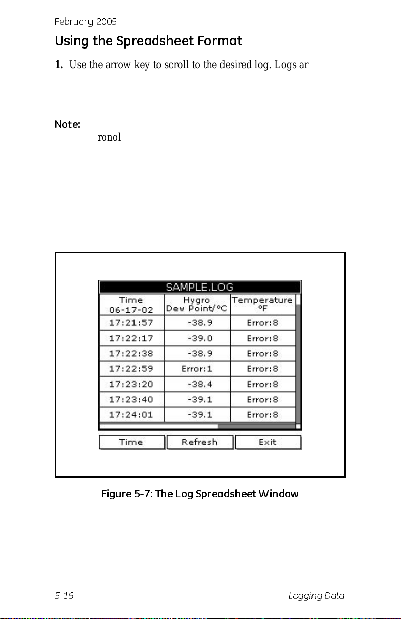
February 2005
Using the Spreadsheet Format
1. Use the arrow key to scroll to the desired log. Logs are
associated with the site file in use at the time the log is cre ated
or run. If you do not see the desired log in the list, refer to
Viewing All Logs on page 5-9 to display all the existing logs.
Note:
The list of log files in the Log Manager can be listed
chronologically or alphabetically. Refer to Sorting Files
in the Site/Drive/Log Manag er on page 6-15.
2. Press
3. Use the arrow key to scro ll to View and press
[MENU].
[ENTER].
4. Use the arrow key to scro ll to Spreadsheet and press
[ENTER]. A screen similar to Figure 5-7 below appears.
Figure 5-7: T h e Log Spreadsh e et W in d ow
5-16 Logging Data
Page 94
Febr uar y 20 0 5
Using the Spreadsheet Format (cont.)
5. Use the [] and [] keys to scroll to other columns, or the
[
] or [] keys to scroll backward or forward in time.
6. Do one of the following:
• To adjust the time scal e, pre ss [F1] (Time) and refer to
Adjusting the Time Scale below.
• T o exi t and retur n to taki ng measurem ents, pre ss [F3] (Exit)
twice and then press
Viewing Data at a Specific Time
1. The Enter Time window appears. Use the arrow keys to scr oll
to the desired text box. Press
2. Use the numeric keys to enter the desired number and press
[ENTER].
3. Repeat steps 1 and 2 for other entries.
[MENU].
[ENTER] to open the box.
4. When you have finished, press
spreadsheet. The PM880 displays the data nearest the time
entered.
[F3] (OK) to exit and view the
What’s Next?
Do one of the following:
• T o return to the Log Manager and view another log, press
[F3] (Exit) and then p ress [MENU]. Return to Using the
Graph Format on page 5-12.
• T o view logs using the spreadsheet for mat, pr ess [F3]
(Exit), then pr ess
Spreadsheet Format on the previous page.
[MENU] and proceed to Using the
• T o exi t and retur n to taki ng measurem ents, pre ss [F3] (Exit)
twice and then press
Logging Data 5-17
[MENU].
Page 95
Febr uar y 20 0 5
Chapter 6
Managing Files
The PM880 program provides three usefu l tools for managing
multiple files: the Site Manager, Drive Manager and Log
Manager. The Site Manager enables you to create , rec all, edit,
rename and delete site file s, the Drive Manager enables you to
transfer and delete all types of files the PM880 can generate,
while the Log Manager lets you rename, copy and de lete log f iles.
Use the following sections to pe rform the desired task:
• save a new site file - page 6-2
• recall an existing si te file - page 6-4
• save changes to an existing site file - page 6-5
• rename a site or log file - page 6-6
• copy (clone) a log - page 6-9
• delete all types of files - page 6-13
• sort files in the Site/Drive/Log Manager (chronologically
or alphabetically) - page 6-15
The Site and Log Managers have additional commands for
printing and all the Managers have the ability to transfer files to
and from a PC. For more details on these functions ref er to
Chapter 7, Using the PM880 with a PC and Printer.
Managing Files 6-1
Page 96
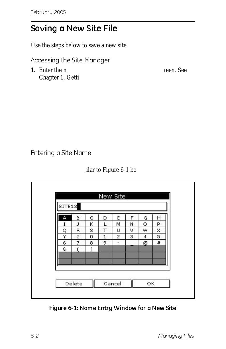
February 2005
Saving a New Site File
Use the steps below to save a new site.
Accessing the Site Manager
1. Enter the necessary data and properly setup the screen. See
Chapter 1, Getting Started, fo r entering data.
2. If the menu is not active, press
3. Use the arrow key to scro ll to Site and press
4. Use the arrow key to scro ll to Site Manager and press
[ENTER].
5. Press
6. Use the arrow key to scro ll to File and press
[MENU].
[MENU].
[ENTER].
[ENTER].
Entering a Site Name
1. Use the arrow key to scro ll to New and press [ENTER]. The
screen appears simila r to Figur e 6-1 below.
Figure 6-1: Na m e En try W i n dow for a Ne w Sit e
6-2 Managing Files
Page 97
Febr uar y 20 0 5
Saving a New Site File (cont.)
Entering a Site Name (cont.)
2. Use the arrow keys to scroll to the desire d letter or number
and press
unwanted letters or numbers.
3. Repeat this procedure until you have created the desired site
name of up to eight characters.
[ENTER]. Press [F1] (Delete) to delete any
4. When you have finished, press
5. The PM880 prompts asks you if you wa nt to save the site as a
template. Saving the site file as a template is useful when you
need to create multiple site s with similar data. At the prompt,
do one of the following:
[F3] (OK).
• Press [F2] (No) if you do not want to us e it as a template, or
• Press [F3] (Yes) if you do want to use it as a template.
6. Press
7. Press
[F3] (Exit).
[MENU]. The new site file is displayed in the upper le ft
corner of the screen.
Managing Files 6-3
Page 98
February 2005
Recalling a Site File
Use the following steps to recal l a previ ously programmed site
file:
Accessing the Site Manager
1. If the menu is not active, press [MENU].
2. Use the arrow key to scro ll to Site and press
[ENTER].
3. Use the arrow key to scro ll to Site Manager and press
[ENTER].
Retrieving the Site File
1. Use the arrow key to scroll to the desired site.
Note:
2. Press
3. Use the arrow key to scro ll to File and press
4. Use the arrow key to scro ll to Open and press
5. The PM880 asks you to confirm, press
6. Press
7. Press
The list of site files in the Site Manager can be listed
chronologically or alphabetically. Refer to Sorting Files
in the Site Manager on page 6-15.
[MENU].
[ENTER].
[ENTER].
[F3] (Yes).
[F3] (Exit).
[MENU]. The PM880 displays the new site file in the
upper-left corner of the screen .
6-4 Managing Files
Page 99
Febr uar y 20 0 5
Saving a Site File
Saving changes to an existing site can be done from the Sit e
Menu or the Site Manager.
Using the Site Menu
1. If the menu is not active, press [MENU].
2. Use the arrow keys to scroll to Site and press
3. Use the arrow keys to scroll to Save Now and press
[ENTER].
[ENTER].
4. The PM880 prompts you to save the current site, pres s
(Yes).
5. Press
[MENU]. The PM880 displays the current site fi le in the
upper-left corner of the screen .
Using the Site Manager
1. If the menu is not active, press [MENU].
2. Use the arrow key to scro ll to Site and press
3. Use the arrow key to scro ll to Site Manager and press
[ENTER].
4. Press
[MENU].
5. Use the arrow key to scro ll to File and press
6. Use the arrow key to scro ll to Save and press
7. The PM880 asks you to confirm, press
8. Press
[F3] (Exit).
[ENTER].
[ENTER].
[ENTER].
[F3] (Yes).
[F3],
9. Press
[MENU]. The PM880 displays the new site file in the
upper-left corner of the screen .
Managing Files 6-5
Page 100
Renaming a Site or Lo g File
Use the appropriate section that follows to rename:
• a site file, refer to the section below.
• a log file, refer to page 6-8.
Renaming a Site File
The PM880 offers two ways to rename fil es. In the Site Manager
you can use the following commands:
• Save As to create a copy of the file with a different name
• Rename to change the name of the site file.
Use the steps below to perform the desir ed task.
Accessing the Site Manager
1. If the menu is not active, press [MENU].
2. Use the arrow key to scro ll to Site and press
3. Use the arrow key to scro ll to Site Manager and press
[ENTER].
[ENTER].
Renaming a Site File
1. Use the arrow key to scroll to the desired site.
Note:
2. Press
3. Use the arrow key to scro ll to File and press
4. Use the arrow key to scro ll to:
The list of site files in the Site Manager can be listed
chronologically or alphabetically. Refer to Sorting Files
in the Site/Drive/Log Manag er on page 6-15.
[MENU].
[ENTER].
• Save As and press [ENTER] - to create a copy of the file
with a different name .
• Rename and press [ENTER] - to change the name of the
site file.
Test Equipment Depot - 800.517.8431 - 99 Washington Street Melrose, MA 02176
FAX 781.665.0780 - TestEquipmentDepot.com
 Loading...