

Page 1
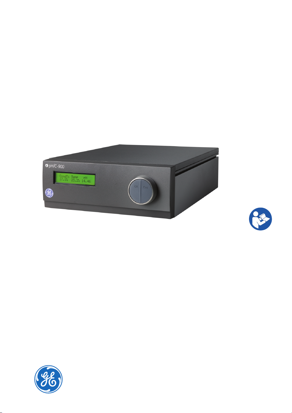
Monitor pH/C-900
Operating Instructions
Original instructions
Page 2

Page intentionally left blank
Page 3

Table of Contents
Table of Contents
51 Introduction ..........................................................................................................
51.1 Prerequisites ...........................................................................................................................................
51.2 Important user information .............................................................................................................
71.3 Regulatory information ......................................................................................................................
91.4 User documentation ...........................................................................................................................
112 Safety instructions ...............................................................................................
112.1 Safety precautions ...............................................................................................................................
152.2 Labels .........................................................................................................................................................
162.3 Emergency procedures ......................................................................................................................
172.4 Recycling information .........................................................................................................................
192.5 Declaration of Hazardous Substances (DoHS) ........................................................................
213 System description ..............................................................................................
223.1 Illustrations ..............................................................................................................................................
253.2 pH electrode ............................................................................................................................................
253.3 Conductivity cell ....................................................................................................................................
264 Installation ............................................................................................................
274.1 Unpacking ................................................................................................................................................
274.2 Site requirements ..................................................................................................................................
284.3 Installing the conductivity cell ........................................................................................................
284.4 Connecting electrical signal cables .............................................................................................
294.5 Installing the pH electrode ...............................................................................................................
304.6 Inserting the pH electrode ................................................................................................................
304.7 Connecting to chart recorder .........................................................................................................
314.8 Connecting to communication link ..............................................................................................
314.9 Connecting to supply voltage .........................................................................................................
324.10 Preparing the instrument for use ..................................................................................................
335 Operation ..............................................................................................................
345.1 Switching on the instrument ...........................................................................................................
345.2 Menu selection and settings ...........................................................................................................
405.3 Setup menu .............................................................................................................................................
485.4 Reading pH and conductivity values ...........................................................................................
495.5 Setting conductivity scale .................................................................................................................
505.6 Calibrating pH and conductivity ....................................................................................................
505.6.1 Calibrating pH .................................................................................................................................
525.6.2 Calibrating conductivity ..............................................................................................................
525.7 Using an external chart recorder ..................................................................................................
535.8 Storage and shut-down .....................................................................................................................
545.9 Restart after power failure ...............................................................................................................
Monitor pH/C-900 Operating Instructions 29-0549-25 AB 3
Page 4

Table of Contents
556 Maintenance .........................................................................................................
566.1 Cleaning before planned service ...................................................................................................
566.2 Periodic maintenance .........................................................................................................................
566.3 Cleaning the conductivity cell .........................................................................................................
576.4 Cleaning the pH electrode ................................................................................................................
586.5 Changing pH electrode ......................................................................................................................
586.6 Cleaning the conductivity flow cell ...............................................................................................
596.7 Changing conductivity flow cells ...................................................................................................
596.8 Instrument housing .............................................................................................................................
607 Troubleshooting ...................................................................................................
607.1 General ......................................................................................................................................................
607.2 Problems and corrective actions ...................................................................................................
647.3 Error messages ......................................................................................................................................
668 Reference information ........................................................................................
668.1 Menu overview .......................................................................................................................................
678.2 Technical specifications .....................................................................................................................
708.3 Health and Safety Declaration Form ...........................................................................................
728.4 Accessories and spare parts ...........................................................................................................
4 Monitor pH/C-900 Operating Instructions 29-0549-25 AB
Page 5

1 Introduction
Purpose of the Operating
Instructions
The Operating Instructions provides you with the instructions needed to handle Monitor
pH/C-900 in a safe way.
1.1 Prerequisites
In order to operate Monitor pH/C-900 safely, and according to the intended purpose,
the following prerequisites must be met:
•
You should be acquainted with the use of bioprocessing equipment and with the
handling of biological materials.
•
You must read and understand the Safety chapter of these Operating Instructions.
•
The systemmustbe installed according to theinstructions in the Installationchapter.
1 Introduction
About this chapter
This chapter contains important user information, a description of the intended use of
Monitor pH/C-900, regulatory information, list of associated documentation, definitions
of safety notices, etc.
1.2 Important user information
Read this before operating the
product
All users must read the entire Operating Instructions before installing, operating or
maintaining the product.
Always keep the Operating Instructions at hand when operating the product.
Monitor pH/C-900 Operating Instructions 29-0549-25 AB 5
Page 6

1 Introduction
1.2 Important user information
Do not operate the product in any other way than described in theuser documentation.
If you do, you may be exposed to hazards that can lead to personal injury and you may
cause damage to the equipment.
Intended use
Monitor pH/C-900 is intended for research use only, and shallnot be used in any clinical
procedures, or for diagnostic purposes.
Safety notices
This user documentation contains safety notices (WARNING, CAUTION, and NOTICE)
concerning the safe use of the product. See definitions below.
WARNING
WARNING indicates a hazardous situation which, if not avoided,
could resultin death or serious injury.It isimportant notto proceed
until all stated conditions are met and clearly understood.
CAUTION
CAUTION indicates a hazardous situation which, if not avoided,
could result in minor or moderate injury. It is important not to proceed until all stated conditions are met and clearly understood.
NOTICE
NOTICE indicates instructions that must be followed to avoid
damage to the product or other equipment.
Notes and tips
Note:
Tip:
6 Monitor pH/C-900 Operating Instructions 29-0549-25 AB
A note is used to indicate information that is important for trouble-free and
optimal use of the product .
A tip contains useful information that can improve or optimize your procedures.
Page 7

Typographical conventions
Software items areidentified in thetext bybold italic text. A colonseparates menulevels,
thus File:Open refers to the Open command in the File menu.
Hardware items are identified in the text by bold text (for example, Power).
1.3 Regulatory information
In this section
This sectiondescribes the directivesand standards thatarefulfilled by MonitorpH/C-900.
Manufacturing information
The table below summarizes the required manufacturing information. For further information, see the EU Declaration of Conformity (DoC) document.
1 Introduction
1.2 Important user information
ContentRequirement
Conformity with EU Directives
This product complies with the European directives listed in the table, by fulfilling the
corresponding harmonized standards.
GE Healthcare Bio-Sciences AB,Name and address of manufacturer
Björkgatan 30, SE 751 84 Uppsala, Sweden
TitleDirective
Electromagnetic Compatibility (EMC) Directive2004/108/EC
Low Voltage Directive (LVD)2006/95/EC
Monitor pH/C-900 Operating Instructions 29-0549-25 AB 7
Page 8

1 Introduction
1.3 Regulatory information
CE marking
The CE marking and the corresponding EU Declaration of Conformity is valid for the instrument when it is:
•
used as a stand-alone unit, or
•
connected to otherproductsrecommendedordescribed in the userdocumentation,
and
•
used in the same state as it was delivered from GE, except for alterations described
in the user documentation.
International standards
This product fulfills the requirements of the following standards:
NotesDescriptionStandard
EN/IEC 61010-1,
UL 61010-1,
CAN/CSA-C22.2
No. 61010-1
EN 61326-1
FCC compliance
This device complies with part 15 of the FCC Rules. Operation is subject to the following
two conditions: (1) This device may not cause harmful interference, and (2) this device
must acceptanyinterferencereceived,including interference that maycauseundesired
operation.
Note:
This equipment has been tested and found to comply with the limits for a Class B digital
device, pursuant to part 15 of the FCC Rules. These limits are designed to provide reasonable protection against harmful interference in a residential installation. This equipment generates, uses and can radiate radio frequency energy and, if not installed and
used in accordance with the instructions, may cause harmful interference to radio
Safety requirements for electrical
equipment for measurement,
control, and laboratory use
Electrical equipment formeasurement, control and laboratory use
- EMC requirements
The user is cautioned that any changes or modifications not expressly approved
by GE could void the user’s authority to operate the equipment.
EN standard isharmonized
with EU directive
2006/95/EC
EN standard isharmonized
with EU directive
2004/108/EC
8 Monitor pH/C-900 Operating Instructions 29-0549-25 AB
Page 9

communications. However, there is no guarantee that interference will not occur in a
particular installation. If this equipment does cause harmful interference to radio or
television reception, which can be determined by turning the equipment off and on, the
user is encouraged to try to correct the interference by one or more of the following
measures:
•
Reorient or relocate the receiving antenna.
•
Increase the separation between the equipment and receiver.
•
Connect the equipment into an outlet on a circuit different from that to which the
receiver is connected.
•
Consult the dealer or an experienced radio/TV technician for help.
Regulatory compliance of
connected equipment
Any equipment connected to Monitor pH/C-900 should meet the safety requirements
of EN/IEC 61010-1,or relevantharmonized standards.Within EU, connected equipment
must be CE marked.
1 Introduction
1.3 Regulatory information
Environmental conformity
This product conforms to the following environmental requirements.
TitleRequirement
Restriction of Hazardous Substances (RoHS) Directive2011/65/EU
Waste Electrical and Electronic Equipment (WEEE) Directive2012/19/EU
ACPEIP
Regulation (EC)
No 1907/2006
Administration onthe Control of PollutionCaused by Electronic
Information Products, China Restriction of Hazardous Substances (RoHS)
Registration, Evaluation, Authorization and restriction of
CHemicals (REACH)
1.4 User documentation
In addition to these Operating Instructions, the documentation package supplied with
Monitor pH/C-900 also includes product documentation binders containing detailed
specifications and traceability documents.
Monitor pH/C-900 Operating Instructions 29-0549-25 AB 9
Page 10

1 Introduction
1.4 User documentation
The mostimportant documents inthedocument package withregardtotechnical aspects
of Monitor pH/C-900 are listed below.
System-specific documentation
ContentUser documentation
Monitor pH/C-900 Operating
Instructions
EU Declarationof Conformity for
Monitor pH/C-900
Detailed system description.Comprehensive user
instructions, method creation, operation, advanced maintenance and troubleshooting.
Document whereby the manufacturer ensures
that theproduct satisfies andis in conformitywith
the essentialrequirementsof the applicabledirectives.
10 Monitor pH/C-900 Operating Instructions 29-0549-25 AB
Page 11

2 Safety instructions
About this chapter
This chapter describes safety compliance, safety labels, general safety precautions,
emergency procedures, power failure and recycling of Monitor pH/C-900.
In this chapter
This chapter contains the following sections:
2 Safety instructions
See pageSection
112.1 Safety precautions
152.2 Labels
162.3 Emergency procedures
2.1 Safety precautions
General precautions
Always followtheseGeneral precautions toavoidinjury whenusing the MonitorpH/C-900
instrument.
WARNING
Do not operate the product in any other way than described in the
Monitor pH/C-900 Operating Instructions.
172.4 Recycling information
192.5 Declaration of Hazardous Substances (DoHS)
Monitor pH/C-900 Operating Instructions 29-0549-25 AB 11
Page 12

2 Safety instructions
2.1 Safety precautions
Personal protection
WARNING
Only properly trained personnel may perform operation and user
maintenance of the product.
WARNING
Always useappropriatePersonal Protective Equipment (PPE)during
operation and maintenance of this product.
WARNING
Hazardous substances and biological agents. When using haz-
ardous chemicaland biological agents, take all suitable protective
measures, such aswearingprotectiveglassesand gloves resistant
to the substances used. Follow local and/or national regulations
for safe operation and maintenance of Monitor pH/C-900.
WARNING
Spread of biological agents. Theoperator hastotake allnecessary
actions toavoid spreading hazardous biologicalagents. The facility
must comply with the national code of practice for biosafety.
Installing and moving the
instrument
WARNING
Protective ground. The product must always be connected to a
grounded power outlet.
12 Monitor pH/C-900 Operating Instructions 29-0549-25 AB
Page 13

2 Safety instructions
2.1 Safety precautions
WARNING
Power cord. Only use power cords with approved plugs delivered
or approved by GE.
WARNING
Access to power switch and power cord with plug. Do not block
access to the power switch and power cord. The power switch
must always be easy to access. The power cord with plug must
always be easy to disconnect.
CAUTION
Make sure that the system is placed on a stable, level bench with
adequate space for ventilation.
System operation
Maintenance
WARNING
If liquid is spilled on the equipment, the electrical power supply
must be disconnected immediately. The equipment must be completely dry on the inside and the outside before reconnecting the
power supply.
WARNING
Electrical shock hazard. All repairs should be done by service
personnel authorized by GE. Do not open any covers or replace
parts unless specifically stated in the user documentation.
Monitor pH/C-900 Operating Instructions 29-0549-25 AB 13
Page 14
2 Safety instructions
2.1 Safety precautions
WARNING
Disconnect power. Always disconnect powerfrom theinstrument
before performing any maintenance task.
WARNING
Disconnect power. Always disconnect powerfrom theinstrument
before replacing fuses.
WARNING
For continued protection from fire hazard, replace only with same
type and rating of fuse.
WARNING
Use only GE parts. Only spare parts and accessories that are ap-
proved orsupplied byGE maybe used for maintaining or servicing
the product.
WARNING
Corrosive substance. NaOH is corrosive and therefore dangerous
to health. When using hazardous chemicals, avoid spillage and
wear protective glasses and other suitable Personal Protective
Equipment (PPE).
CAUTION
Hazardous chemicals or biological agents in UV flow cell. Make
sure that the entire flow cell has been flushed thoroughly with
bacteriostatic solution(e.g., NaOH) anddistilled water, before service
and maintenance.
14 Monitor pH/C-900 Operating Instructions 29-0549-25 AB
Page 15

2.2 Labels
Introduction
This section describes the system label on Monitor pH/C-900 and its meaning.
System label
The illustration below shows the system label.
2 Safety instructions
2.2 Labels
Figure 2.1: System Label
Note:
The system label information is explained in the table below.
Monitor pH/C-900 Operating Instructions 29-0549-25 AB 15
The specific data shown on the system label below is only an example. Actual
data is specific for each individual system and may vary from systemto system.
DescriptionLabel text
GE Code number.Code no:
GE Serial number.Serial no:
Manufacturing year.Mfg Year:
Voltage.Voltage:
Supply voltage frequency.Frequency:
Max power.Max power:
Fuse.Fuse:
Page 16

2 Safety instructions
2.2 Labels
DescriptionLabel text
Warning! Read the user documentation before using
the system. Do not open any covers or replace parts
unless specifically stated in the user documentation.
This symbolindicates that wasteelectrical and electronic equipmentmust notbe disposed as unsorted municipal waste and must be collected separately. Please
contact an authorized representative of the manufacturer for information concerning the decommissioning
of equipment.
This symbol indicates that the product contains hazardous materials in excess of the limits established by
the Chinese standard SJ/T11363-2006 Requirements
for Concentration Limits for Certain Hazardous Substances in Electronics.
The system complies with applicable European directives.
The system complies with the requirements for
electromagnetic compliance (EMC)in Australia andNew
Zealand.
This symbol indicates that Monitor pH/C-900 has been
certified bya Nationally RecognizedTestingLaboratory
(NRTL). NRTL meansanorganization, which isrecognized
by the US Occupational Safety and Health Administration (OSHA) as meeting the legal requirements of Title
29 of the Code of Federal Regulations (29 CFR), Part
1910.7.
2.3 Emergency procedures
Introduction
This section describes how to perform an emergency shutdown of Monitor pH/C-900.
The section also describes the result in the event of power failure.
16 Monitor pH/C-900 Operating Instructions 29-0549-25 AB
Page 17

Emergency shutdown
In an emergency situation, do as follows to stop the run:
Switch off power to the instrument by switching the On/off switch on the rear panel to
the (O) position. If required, disconnect the mains power cord. The run is interrupted
immediately.
Power failure
In the event of power failure the run is interrupted immediately.
2.4 Recycling information
Decontamination
Monitor pH/C-900 shall be decontaminatedbefore decommissioning and all local regulations shall be followed with regard to scrapping of the equipment.
2 Safety instructions
2.3 Emergency procedures
Disposal, general instructions
When takingMonitor pH/C-900 outof service, thedifferent materials mustbeseparated
and recycled according to national and local environmental regulations.
Recycling of hazardous
substances
Monitor pH/C-900 contains hazardous substances. Detailed information is available
from your GE representative.
Monitor pH/C-900 Operating Instructions 29-0549-25 AB 17
Page 18

2 Safety instructions
2.4 Recycling information
Disposal of electrical
components
Waste ofelectrical and electronic equipmentmust not bedisposed as unsortedmunicipal
waste and must be collected separately. Please contact an authorized representative
of the manufacturer for information concerning the decommissioning of equipment.
18 Monitor pH/C-900 Operating Instructions 29-0549-25 AB
Page 19

2 Safety instructions
2.5 Declaration of Hazardous Substances (DoHS)
2.5 Declaration of Hazardous Substances (DoHS)
根据SJ/T11364-2006《电子信息产品污染控制标识要求》特提供如下有关污染 控制方面的信息。
The following product pollution control information is provided according to SJ/T11364-2006 Marking
for Control of Pollution caused by Electronic Information Products.
电子信息产品污染控制标志说明
Explanation of Pollution Control Label
该标志表明本产品含有超过SJ/T11363-2006《电子信息产品中有毒有害物质的限
量要求》中限量的有毒有害物质。标志中的数字为本产品的环保使用期,表明本
产品在正常使用的条件下,有毒有害物质不会发生外泄或突变,用户使用本产品
不会对环境造成严重污染或对其人身、财产造成严重损害的期限。单位为年。
为保证所申明的环保使用期限,应按产品手册中所规定的环境条件和方法进行正
常使用,并严格遵守产品维修手册中规定的期维修和保养要求。
产品中的消耗件和某些零部件可能有其单独的环保使用期限标志,并且其环保使
用期限有可能比整个产品本身的环保使用期限短。应到期按产品维修程序更换那
些消耗件和零部件,以保证所申明的整个产品的环保使用期限。
本产品在使用寿命结束时不可作为普通生活垃圾处理,应被单独收集妥善处理。
This symbolindicates the productcontains hazardous materialsin excess ofthe limits
established bythe Chinese standard SJ/T11363-2006RequirementsforConcentration
Limits for Certain Hazardous Substances in Electronic Information Products. The
number in the symbol is the Environment-friendly Use Period (EFUP), which indicates
the period during which the toxic or hazardous substances or elements contained in
electronic information products will not leak or mutate under normal operating conditions so that the use of such electronic information products will not result in any
severe environmental pollution, any bodily injury or damage to any assets. The unit
of the period is “Year”.
In order to maintain the declared EFUP, the product shall be operated normally according to the instructions and environmental conditions as defined in the product
manual, and periodic maintenance schedulesspecified in Product Maintenance Procedures shall be followed strictly.
Consumables or certain parts may have their ownlabel withan EFUP value less than
the product. Periodic replacement of those consumables or parts to maintain the
declared EFUP shallbe doneinaccordance with theProductMaintenance Procedures.
This product must not be disposed of as unsorted municipal waste, and must be
collected separately and handled properly after decommissioning.
Monitor pH/C-900 Operating Instructions 29-0549-25 AB 19
Page 20

2 Safety instructions
2.5 Declaration of Hazardous Substances (DoHS)
有毒有害物质或元素的名称及含量
Name and Concentration of Hazardous Substances
产品中有毒有害物质或元素的名称及含量
Table of Hazardous Substances’ Name and Concentration
部件名称
Component name
0:
X:
•
0:
X:
•
表示该有毒有害物质在该部件所有均质材料中的含量均在SJ/T11363-2006 标准规定的限
量要 求以下
表示该有毒有害物质至少在该部件的某一均质材料中的含量超出SJ/T11363-2006 标准规
定的限量要求
此表所列数据为发布时所能获得的最佳信息
Indicates that this toxic or hazardous substance contained in all of the homogeneous materials for this part is below the limit requirement in SJ/T11363-2006.
Indicates that this toxic or hazardous substance contained in at least one of the homogeneous materials used for this part is above the limit requirement in SJ/T11363-2006.
Data listed in the table represents best information available at the time of publication.
有毒有害物质或元素
Hazardous substance
铅
Pb
汞
Hg
镉
Cd
六价铬
Cr6+
多溴联苯
PBB
多溴二苯醚
PBDE
00000X18-1107-76
20 Monitor pH/C-900 Operating Instructions 29-0549-25 AB
Page 21

3 System description
About this chapter
This chapterprovidesa descriptionof Monitor pH/C-900,an on-line monitorfor measurement of pH and conductivity. The monitor can work with standard glass pH electrodes
with a built in liquid-filled reference electrode and BNC connector.
The conductivitymonitor hasa very largedynamic rangefrom 1 μS to 999.9mS/cm and
is therefore suitable for a wide range of applications.
In this chapter
This chapter contains the following sections:
3 System description
See pageSection
223.1 Illustrations
253.2 pH electrode
253.3 Conductivity cell
Monitor pH/C-900 Operating Instructions 29-0549-25 AB 21
Page 22

pH/C-900
1
2
3
3 System description
3.1 Illustrations
3.1 Illustrations
Main unit
Figure 3.1: Monitor pH/C-900 with pH electrode and conductivity flow cell
FunctionPart
Main unit1
pH electrode2
Conductivity flow cell3
22 Monitor pH/C-900 Operating Instructions 29-0549-25 AB
Page 23
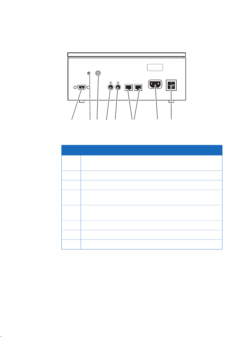
Main unit, backpanel
1 2 3 4 5 6 7 8
pH
Ground
pH
Probe
UniNet -1
Mains
On/off
Analogue out 0-1V
pH
Cond
Conductivity
Flow Cell
Figure 3.2: Backpanel of Monitor pH/c-900, main unit
3 System description
3.1 Illustrations
FunctionPart
1
Conductivity Flow Cell. Connection to conductivity flow cell, 9 pole D-sub
connector
pH Ground. pH signal ground2
pH Probe. Connection to pH electrode, standard BNC socket3
4
Analog out 0–1V pH. Separate recorder output for pH, recorder output
0–1 V
5
Analog out 0–1V Cond. Separaterecorderoutput forconductivity,recorder
output 0–1 V
UniNet-1. Computer network6
Mains. Supply voltage, grounded7
On/off. Instrument power switch8
Monitor pH/C-900 Operating Instructions 29-0549-25 AB 23
Page 24

1
2
3
5
6
7
8
10
9
4
3 System description
3.1 Illustrations
pH electrode
Figure 3.3: Glass pH electrode
FunctionPart
Sealing1
Internal electrolyte bridge containing 4M KCl saturated with AgCl2
Silicone sealing3
Ag/AgCl reference electrode4
Internal annular coaxial ceramic reference junction5
6
24 Monitor pH/C-900 Operating Instructions 29-0549-25 AB
External electrolyte bridge containing 1M KNO
3
Page 25

FunctionPart
O-ring7
Glass electrode containing diluted, buffered KCl8
O-ring9
External annular coaxial ceramic reference junction10
3.2 pH electrode
The pH electrode is of the sealed combination double junction type. It contains a sealed
Ag/AgCl reference which cannot be refilled, an internal electrolyte bridge of 4M KCl saturated withAg/AgCl,an outerelectrolytebridge of 1MKNO3, anannular ceramic reference
junction anda low profilepH membrane. ThepH electrode isdeliveredwith a transparent
cover.
3.3 Conductivity cell
The flow cell has two cylindrical titanium electrodes positioned in the flow path of the
cell. An alternating voltage is applied between the electrodes and the resulting current
is measured and used to calculate the conductivity of the eluent. The monitor controls
the AC frequency and increases it with increasing conductivity between 50 Hz and 50
kHz giving maximum linearity and true conductivity values.
3 System description
3.1 Illustrations
Figure 3.4: Conductivity flow cell
Monitor pH/C-900 Operating Instructions 29-0549-25 AB 25
Page 26

4 Installation
4 Installation
About this chapter
This chapter provides required information to enable users and service personnel to
unpack, install, move and transport Monitor pH/C-900.
Precautions
WARNING
Before attempting to perform any of the procedures described in
this chapter, you must read and understand all contents of the
Safety instructions chapter.
In this chapter
This chapter contains the following sections:
See pageSection
274.1 Unpacking
274.2 Site requirements
284.3 Installing the conductivity cell
284.4 Connecting electrical signal cables
294.5 Installing the pH electrode
304.6 Inserting the pH electrode
304.7 Connecting to chart recorder
314.8 Connecting to communication link
314.9 Connecting to supply voltage
26 Monitor pH/C-900 Operating Instructions 29-0549-25 AB
Page 27

4.1 Unpacking
Unpack the instrument and check the itemsagainst thesupplied packinglist. Check the
equipment for damage before starting assembly and installation. There are no loose
parts in the transport box. All parts are either mounted on the system or located in the
accessory kitbox. If any damage isfound, document thedamage, and contactyour local
GE representative.
It is recommended that all packing materials should be retained if onward transport of
the instrument is expected.
4.2 Site requirements
4 Installation
4.1 Unpacking
See pageSection
324.10 Preparing the instrument for use
RequirementParameter
Indoor useOperation site
Maximum 2000 mAltitude
100/240 V AC ±10%, 50/60 HzElectrical power
Overvoltage category IITransient overvoltages
4°C to 40°CAmbient temperature
In ÄKTAexplorer or ÄKTApurifier.Placement
20% to 95% relative humidity (noncondensing)Humidity
84 to 106 kPa (840 to 1060 mbar)Atmospheric pressure
2Pollution degree
The instrument should be located in a place of low temperature variations, away from
heat sources, draughts and direct sunlight.
To ensure correct ventilation a free space of 0.1 m is required behind and in front of the
instrument. Do not use any soft materialunder theinstrument, to ensure thatthe ventilation inlet in the front is not blocked.
Monitor pH/C-900 Operating Instructions 29-0549-25 AB 27
Page 28

4 Installation
4.3 Installing the conductivity cell
4.3 Installing the conductivity cell
NOTICE
The mainspowertoMonitor pH/C-900 must beswitchedoff before
connecting the instrument to any cells or external equipment.
ActionStep
Place theconductivity cell ina suitableplace, for exam-
1
ple on the shelf of the Monitor UV-900 using the clip
provided with the UV monitor. The cell can be placed
up to 1.5 m from the monitor housing.
Connect the conductivity cell to the socket Conductiv-
2
ity Flow Cell on the rear panel of the instrument.
Connect the tubing with the Fingertight connectors.
3
The flow cell itself does not have a recommended flow
direction. In conjunction with the pH electrode, place
the conductivity flow cell and select its flow direction
so that the screw head end of the flow cell faces the
pH flow cell.
4.4 Connecting electrical signal cables
WARNING
Power cord. Only use power cords with approved plugs delivered
or approved by GE.
NOTICE
The mainspowertoMonitor pH/C-900 must beswitchedoff before
connecting the instrument to any cells or external equipment.
The sockets for electrical signals are located on the rear panel.
28 Monitor pH/C-900 Operating Instructions 29-0549-25 AB
Page 29

Analogue out 0-1V
UniNet 1
Mains On/off
pH Cond
Conductivity
Flow Cell
pH
Probe
pH
Ground
Figure 4.1: Backpanel of Monitor pH/C-900
4.5 Installing the pH electrode
NOTICE
The mainspowertoMonitor pH/C-900 must beswitchedoff before
connecting the instrument to any cells or external equipment.
4 Installation
4.4 Connecting electrical signal cables
ActionStep
1
Hook the flow cell holder on the right hand side of the housing. Secure it
with the slide clamp.
If the flow cell holder is not used, the flow cell must still be installed at an
angle of 30° from the vertical with the outlet placed higher than the inlet to
prevent air bubbles being trapped in the cell. The flow direction is marked
on the flow cell, see Figure 4.2.
Connect the tubing with the Fingertight connectors.2
Monitor pH/C-900 Operating Instructions 29-0549-25 AB 29
Figure 4.2: pH electrode with flow direction
Page 30

4 Installation
4.6 Inserting the pH electrode
4.6 Inserting the pH electrode
Note:
1
2
3
4
5
Handle the pH electrode with care.
NOTICE
The mainspowertoMonitor pH/C-900 must beswitchedoff before
connecting the instrument to any cells or external equipment.
NOTICE
Never leave the pH electrode in the cell holder when the system is
not used, since this might cause the glass membrane of the electrode todry out. Remove the pH electrode from the cell holderand
fit the end cover filled with a 1:1 mixture of pH 4 buffer and 2 M
KNO3. Do NOT store in water only.
Unpack the pH electrode. Ensure that it is not broken or dry.
Prior to first using the electrode, remove the electrode end cover and immerse the
glass bulb in buffer for 30 minutes.
Remove the dummy electrode from the flow cell and store it in the flow cell holder.
Carefully insert the electrode in the flow cell. Tighten the nut by hand to secure the
electrode.
Note:
Connect the pH electrode cable to the rear of the instrumentto thesocket pH Probe
If the electrode is not fully inserted, the system will leak and a dead volume
will occur in the holder.
4.7 Connecting to chart recorder
NOTICE
The mainspowertoMonitor pH/C-900 must beswitchedoff before
connecting the instrument to any cells or external equipment.
The external chart recorder outputs for pH and conductivityfrom the monitor are 0 V to
1 V. There is also a 4 mA to 20 mA signal available at the same output connectors.
1
Connect the chart recorder to the DIN-socket pH or Cond using the cable supplied:
30 Monitor pH/C-900 Operating Instructions 29-0549-25 AB
Page 31

•
For 0 V to 1 V use wire1 (+)and 2(–). Usea recorder withfloating inputs(i.e., none
of the inputs connected to ground).
or
•
For 4 mA to 20 mA use wire 5 (+) and wire 6 (–).
Note:
2
Set the recorder to 0 V to 1 V or 4 mA to 20 mA input, full scale.
The signal cable is delivered with protective covers on each wire. Do not
remove the protective covers from unused connections as a short circuit
may disturb the measurements.
4.8 Connecting to communication link
NOTICE
The mainspowertoMonitor pH/C-900 must beswitchedoff before
connecting the instrument to any cells or external equipment.
The monitoris intended foruse with ÄKTAexplorer and ÄKTApurifier, andcan be controlled
from a PC running UNICORN™ version 2.20 or higher, using UniNet cables.
Connect twoUniNetcables totheUniNet 1 connectors. The instrumentcanbe connected
in series anywhere between the PC and a termination plug. The UniNet link connects, in
series, the PC with Pump P-900, Monitor pH/C-900, Monitor UV-900 and the Frac-900.
The termination plug is connected to the last instrument in the chain.
4 Installation
4.7 Connecting to chart recorder
4.9 Connecting to supply voltage
WARNING
Protective ground. The product must always be connected to a
grounded power outlet.
1
Make sure the On/off switch is in the OFF-position 0.
2
Connect the supplied mains cable between the instrument and a grounded mains
socket. Any voltage 100 VAC to 240 VAC, 50 Hz to 60 Hz can be used.
The instrument contains no user replaceable fuse.
Monitor pH/C-900 Operating Instructions 29-0549-25 AB 31
Page 32

4 Installation
4.10 Preparing the instrument for use
4.10 Preparing the instrument for use
NOTICE
Any computer used with the equipment must comply with IEC
60950 and be installed and used according to the manufacturer's
instructions.
Before the instrument is ready to use:
•
Set the conductivity cell constant, see Entering the conductivity cell constant, on
page 43.
•
Calibrate thetemperaturesensor, see Calibratingthe temperature sensor, on page 45.
•
Calibrate the pH electrode, see Section 5.6.1 Calibrating pH, on page 50.
Note:
Note:
Note:
Before performingthese procedures you are recommended toreadSection 5.1 Switching
on the instrument, on page 34, Moving between menus,on page34,Returnto main menu,
on page 36, Select value, on page 36 and Main menu overview, on page 36.
The conductivity cell constant is shown on the packaging. Retain the packaging
in case the conductivity cell constant needs to be re-entered.
Measured temperature is the temperature in the conductivity flow cell, which
can differ from the ambient temperature.
When running chromatography using organic solvents, it is recommended
that the pH electrode is removed and the dummy electrode insertedin its place,
as organic solvents will cause pH electrode degeneration.
32 Monitor pH/C-900 Operating Instructions 29-0549-25 AB
Page 33
5 Operation
About this chapter
This chapter provides the information required to safely operate Monitor pH/C-900.
Precautions
5 Operation
WARNING
Before attempting to perform any of the procedures described in
this chapter, you must read and understand all contents of the
Safety instructions chapter.
In this chapter
This chapter contains the following sections:
See pageSection
345.1 Switching on the instrument
345.2 Menu selection and settings
405.3 Setup menu
485.4 Reading pH and conductivity values
495.5 Setting conductivity scale
505.6 Calibrating pH and conductivity
525.7 Using an external chart recorder
535.8 Storage and shut-down
545.9 Restart after power failure
Monitor pH/C-900 Operating Instructions 29-0549-25 AB 33
Page 34
Calibrating
Selftest
Monitor pH/C900
Calibration OK
Cond Temp pH
25.4% 22.9°C 11.50
5 Operation
5.1 Switching on the instrument
5.1 Switching on the instrument
Note:
1
2
The monitor can be used immediately but the full specifications are not obtained
until after a 1 hour warm–up.
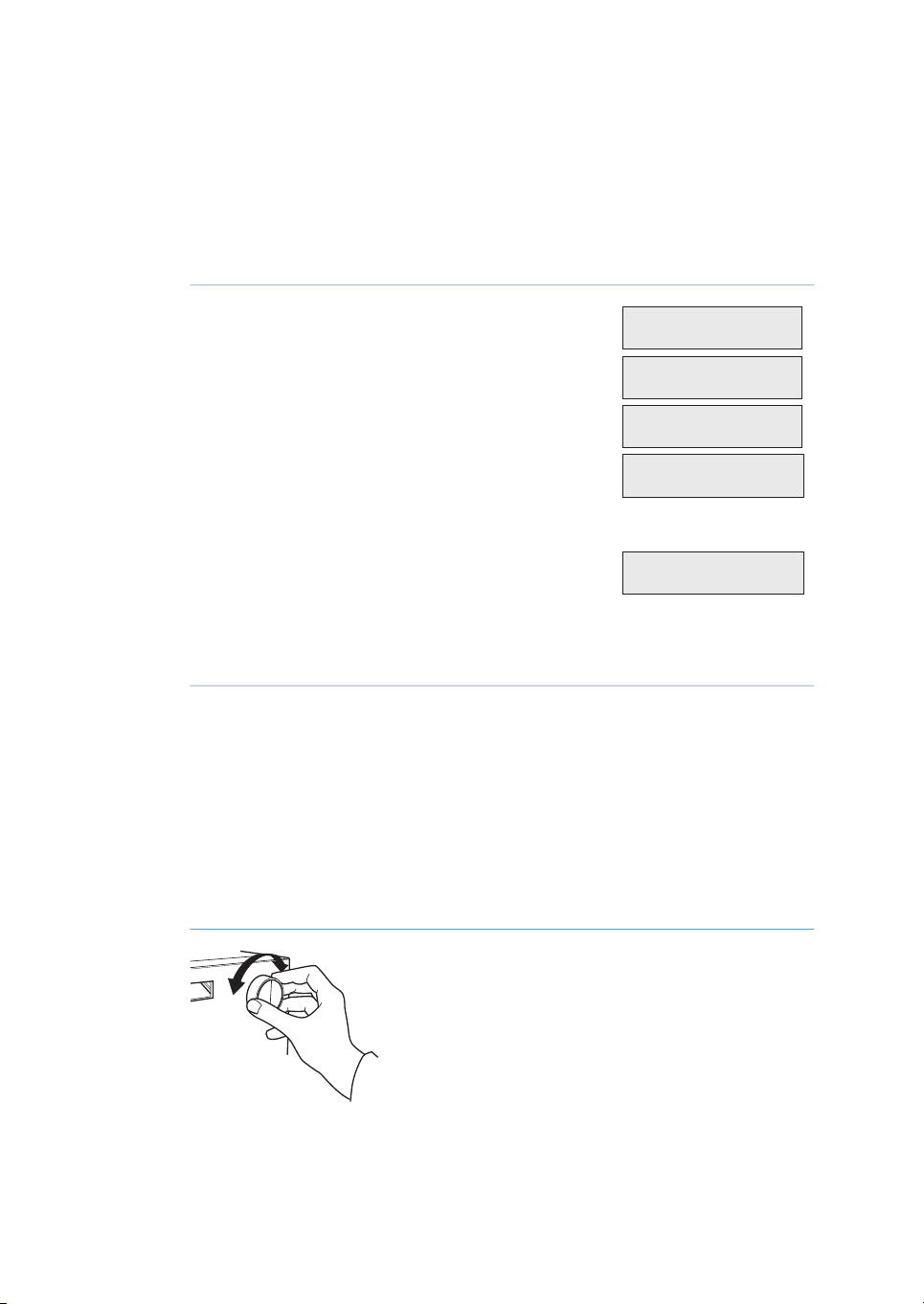
Switch onthe instrument atthe On/off switch onthe
rear panel.
At switch on, the instrument performs a self test and
then starts calibration. After approximately 30 seconds the display shows Calibration OK.
The displayshowsCond Temp pH and the instrument
is ready to use. All parameters are factory set to default values.
If the conductivity cell is not connected the Temp
and Cond fields are blank. The pH field is blank if
Show pH is set to off.
DisplayActionStep
5.2 Menu selection and settings
Moving between menus
A specific menu is selected by turning the front selection dial clockwise or counterclockwise. When the required menu is visible the menu or selection is accepted by pressing
the OK-button.
Action
Turn dial clockwise or counterclockwise to select menus.
34 Monitor pH/C-900 Operating Instructions 29-0549-25 AB
Page 35

Main menu 1
Main menu 2
Main menu 3
Main menu 4
Main menu 5
Main menus Sub menus Sub menus
Sub menu 2.3.1
Sub menu 2.3.2
Sub menu 2.1
Sub menu 2.2
Sub menu 2.3
Sub menu 2 .1.1
ESC
OK
ESC
OK
ESC
OK
5 Operation
5.2 Menu selection and settings
Action
Press OK button to select sub-menu.
Press ESC button to return one menu level.
If a menu has sub levels, the sub menu is displayed by pressing the OK button. Pressing
the ESC button moves back one menu level.
Figure 5.1: Moving between sub-menus
Monitor pH/C-900 Operating Instructions 29-0549-25 AB 35
Page 36

Main menu 1
Main menu 2
ESC ESC ESC
ESC
Setup Cond ref temp
( 20.0 °C )
( 22.0 °C )
2
3
1
Cond Temp pH
25.4% 22.9°C 11.50
4.000 mS/cm 22.9°C
5 Operation
5.2 Menu selection and settings
Return to main menu
Pressing ESC repeatedly, alwaysreturns to theMain menu 1 which is themainoperating
menu.
Figure 5.2: Return to main menu
Select value
A cursor below a text or numerical value shows what is affected by the dial. To increase
the value turn the dial clockwise. To decrease the value turn the dial counterclockwise.
The valuecan be resetby turning thedial several clickscounterclockwise.The parameter
(1) being changed is shown in the top left of the display, the current value (2) is shown
below theparameter and thenew value tobe (3)is shown inthe lower rightof thedisplay.
See Figure 5.3.
Main menu overview
36 Monitor pH/C-900 Operating Instructions 29-0549-25 AB
Figure 5.3: Select value
When settingnumericalvalues the cursormoves to theadjacent digit ifthedial isturned
quickly in one direction, to simplify entering large values. The cursor moves back one
decimal place to the right every two seconds if the dial is not turned. The text or numerical value displayed is accepted by pressing the OK button. To cancel, press the ESC
button.
FunctionDisplay
Main operation menu. The menu is accessed from all
position by pressing the ESC button repeatedly.
Alternative display of conductivity with horizontal bar
graph.
Page 37

Set Cond Scale 100%
Set Cond Scale 0%
Calibrate pH
Set pH Analogue Out
Check
Setup
Alarm/Timer 00:30:52
Check Monitor Cell and
Electrode
5 Operation
5.2 Menu selection and settings
FunctionDisplay
Setting conductivity full scale.
Setting conductivity zero point.
Calibration of pH monitor.
Setting the recorder output for the pH measurement.
Check internal operating values. See Check monitor cell
and electrode, on page 37.
Setup conductivity, pH, temp., language, etc. See Sec-
tion 5.3 Setup menu, on page 40.
Set differenttimer option. SeeSetting and using the alarm
timer, on page 39.
Check monitor cell and electrode
A check of the conductivity cell and pH electrode can be performed.
DisplayActionStep
Select main menu Check, press OK.1
Select sub menu Check Monitor cell and Electrode,
2
press OK.
Monitor pH/C-900 Operating Instructions 29-0549-25 AB 37
Page 38

Check Service Mode
Telephone Service
012345678901
Contract Number
012345678901
Serial Number
01234567 YM 012345
Monitor pH/C-900
V1.00
Date of Maintenance
?
Buzzer Test
5 Operation
5.2 Menu selection and settings
The text Passed will appear for 2 seconds if the cell
3
and electrode are indicating reasonable values. If
there are any problemsan error messagewillappear.
Check Service Mode
Service information relevant to the instrument can be checked. Information may not be
available in all menus.
Select main menu Check, press OK.1
Select sub menu Check Service Mode, press OK.2
The service telephone numberis displayed, press OK.3
DisplayActionStep
DisplayActionStep
The service contract number is displayed, press OK.4
The instrument serial number is displayed, press OK.5
The instrument name and software version are dis-
6
played, press OK.
The date of the last service is displayed, press OK.7
A test of the instrument buzzer is performed, press
8
OK.
38 Monitor pH/C-900 Operating Instructions 29-0549-25 AB
Page 39

Setting and using the alarm
Alarm/Timer 12:30:52
Set Alarm 12:32:21
(0) 00
.00.00
Set Timer
(18:34:52) 00
.00.00
Alarm/Timer 12:35:16
Bzz00:33:00
Bzz00:00:29 13:08:45
!!
Set Clock
(12:26:53) 12: 3
6:53
Alarm/Timer o?
OK=o
timer
You can set the alarmfunction to either a fixedalarm time or using a count-down timer.
The default or previous value is shown in parentheses.
Select mainmenuAlarm/Timer, press OK.Thedisplay
1
shows the current time.
Select sub menu Set Alarm, if you want to set an
2
alarm ata fixed time.Press OK to enter thetime value
in the form HH.MM.SS, pressing the OK button after
entering each time unit.
If you want to set a count-down timer, turn the dial
3
to select sub menu Set Timer. Press OK to enter the
countdown value in the form HH.MM.SS, pressing
the OKbutton after enteringeach time unit. An alarm
time and a count-down timer cannot both be set.
5 Operation
5.2 Menu selection and settings
DisplayActionStep
Press ESC button to return tothe Alarm/Timer menu
4
which now showsthe set alarm time or count-down
time as BzzHH:MM:SS.
When thealarm time isdue or the count-down timer
5
reaches 00:00:00, an alert display is shown and the
instrument beeps,untilthe OK button ispressed. The
display shows the time elapsedsince the alarm, and
the current time.
The alarm timer is based on the internal instrument
clock which can be set in theSet Clock menu placed
after theAlarm/Timermenu. The clockis reset when
the power is turned off.
A set alarm/timer function can be reset by pressing
OK in the menu Alarm/Timer off?.
Monitor pH/C-900 Operating Instructions 29-0549-25 AB 39
Page 40
Insert Access Code:
Setup Conductivity
Setup Cond Temp Comp
(2.0%/°C) 2.0
5 Operation
5.2 Menu selection and settings
Service displays
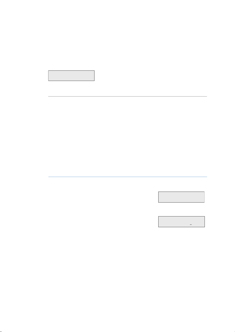
The instrumenthas servicedisplays for useby authorizedservice personnel.If the service
display Insert Access Code: is accidentally selected, press the ESC button to exit to the
normal operation display.
Figure 5.4: Insert access code
5.3 Setup menu
Setting up conductivity
temperature compensation
The conductivityin a buffer is temperature dependent. Torelate conductivity toconcentration and/orcompareconductivity values, temperature compensationshould be used.
The compensationconsists of a compensation factortogether with areference temperature. All conductivity values will then automatically be converted to the set reference
temperature.
Select main menu Setup, press OK.1
Select sub menu Setup Conductivity, press OK.2
Select sub menu Setup Cond Temp Comp, press OK.3
Set a temperature compensation factor, press OK.
4
The factor is expressed in percentage increase of
conductivity per °C increase in temperature. If the
temperature compensation factor is unknown, a
general approximate valueof2% can beset for many
common salt buffers. Set the value to 0 for no temperature compensation.
DisplayActionStep
40 Monitor pH/C-900 Operating Instructions 29-0549-25 AB
Page 41

Setup Cond Ref Temp
(22.3°C) 25. 0
Select sub menu Setup Cond Ref Temp, press OK.
Setup
5
Select the reference temperature to which the measured conductivityvalueswill be converted (normally
20°C or 25°C), press OK.
Calibrating the conductivity cell
Normally it is not necessary to adjust the cell constant as the flow cell is precalibrated
on delivery. Adjustment is only necessary when replacing the conductivity flow cell with
a flowcell whosecell constant is unknown. Itis alsorecommended that theconductivity
flow cell is recalibrated after cleaning. When adjusting the cell constant from UNICORN
select SystemControl:System: Calibrate and then select CondCalib.
Note:
The conductivity temperature compensation must not be used when adjusting
the cell constant. Set the Setup Cond temp comp to 0 (see Setting up conductivity temperature compensation, on page 40). The temperature sensor must
be calibrated before adjusting the cell constant (See Calibrating the temperature
sensor, on page 45)
5 Operation
5.3 Setup menu
DisplayActionStep
Prepare a calibration solution of 1.00 M NaCl, 58.44
1
g/l. Let the solution stand until it is at roomtemperature. This is important for exact measurements.
Fill the flow cell completelywith the calibration solu-
2
tion, by pumping at least 15 ml through the cell with
a syringe.
Stop the flow and wait 15 minutes, until the temper-
3
ature is constant in the range 20°C to 30°C.
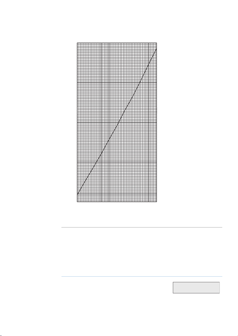
Read the conductivity value displayed and compare
4
it with the theoretical value from the graph, at the
temperature of the calibration solution. If the displayed value and the theoretical value correspond,
no further action is required. If the values differ, proceed with actions 5–8.
Select main menu Setup, press OK.5
DisplayActionStep
Monitor pH/C-900 Operating Instructions 29-0549-25 AB 41
Page 42

Setup Conductivity
Setup Adjust Cond
(83.53mS/cm)
Warning! This will
change cell calib
Setup Adjust Cond
(83.53mS/cm) 86.60
5 Operation
5.3 Setup menu
Select sub menu Setup Conductivity, press OK.6
Select sub menu Setup Adjust Cond, press OK.7
A warning message will be displayed, press OK.8
Enter thetheoretical conductivity value according to
9
the graph, press OK. The new cell constant is automatically calculated and updated.
DisplayActionStep
42 Monitor pH/C-900 Operating Instructions 29-0549-25 AB
Page 43
20 25 30
77
80
85
90
95
97
Temperature (°C)
Conductivity (mS/cm)
Setup
5 Operation
5.3 Setup menu
Entering the conductivity cell
constant
Figure 5.5: Conductivity o f 1. 00 M Na Cl at 20°C to 30°C
After replacing the flow cell, the cell constant has to be set. (The cell constant is shown
on the packaging).
DisplayActionStep
Select main menu Setup, press OK.1
Monitor pH/C-900 Operating Instructions 29-0549-25 AB 43
Page 44

Setup Conductivity
Setup Adj Cell Const
(34.4/cm)
Warning! This will
change cell calib
Setup Adj Cell Const
(34.4/cm) 35. 5
Setup
Setup pH
5 Operation
5.3 Setup menu
DisplayActionStep
Select sub menu Setup Conductivity, press OK.2
Select sub menu Setup Adjust Cell Constant, press
3
OK.
A warning message will be displayed, press OK.4
Enter the cell constant, press OK. The new cell con-
5
stant is updated.
When enteringthe cell constantfromUNICORN select System Control:System:Calibrate
and select Cond_Cell.
Setting up pH temperature
compensation
The relationship between pHandthe output signalfromthe pH electrodeistemperature
dependent. For more accurate measurements during temperature changes, the pH
measurement can be temperature compensated.
In normal applications, if the temperature of the buffers and calibration buffers are
identical, temperature compensation does not need to be on.
When using temperature compensation it is important that the temperature of the pH
electrode is thesame asthat of theconductivity flow cellsince that iswhere the temperature is measured.
DisplayActionStep
Select main menu Setup, press OK.1
Select menu Setup pH, press OK.2
44 Monitor pH/C-900 Operating Instructions 29-0549-25 AB
Page 45

Setup pH Temp Comp
(O) On O
Select sub menu Setup pH Temp Comp, press OK.3
Setup
Setup pH
Setup Show pH
(On)
Set the temperature compensation On or Off, press
4
OK.
Setting up the pH display
Normally thepH isdisplayedin themain operating menuor itsalternative(see Figure5.6).
If not required the pH display can be set to off.
Select main menu Setup, press OK.1
5 Operation
5.3 Setup menu
DisplayActionStep
DisplayActionStep
Select menu Setup pH, press OK2
Select sub menu Setup Show pH, press OK.3
Set the pH display on or off, press OK.4
Calibrating the temperature
sensor
Calibration of the temperature sensor in the conductivity flow cell is only necessary if
the monitor is used in high accuracy measurement or the conductivity flow cell is replaced.
Place the flow cell together with a precision ther-
1
mometer insidea box orempty beaker toensurethat
they are not exposed to draft. Leave them for 15
minutes to let the temperature stabilize.
DisplayActionStep
Monitor pH/C-900 Operating Instructions 29-0549-25 AB 45
Page 46

Setup
Setup Temperature
Setup Adjust Temp
(23.5°C)
Warning! This will
change temp calib
Setup Adjust Temp
(23.5°C) 25.0
Setup
Setup Temperature
Setup Show Temp
(On) On
O
5 Operation
5.3 Setup menu
DisplayActionStep
Read the temperature on the thermometer.2
Select main menu Setup, press OK.3
Select sub menu Setup Temperature, press OK.4
Select sub menu Setup Adjust Temp, press OK.5
A warning message will be displayed, press OK.6
Enter the temperature shown on the thermometer,
7
press OK.
Setting up the temperature
display
Display ofthe temperature in the conductivity flowcell, in the main operatingmenu, can
be enabled or disabled.
Select main menu Setup, press OK.1
Select sub menu Setup Temperature, press OK.2
Select sub menu Setup Show Temp, press OK.3
DisplayActionStep
46 Monitor pH/C-900 Operating Instructions 29-0549-25 AB
Page 47

Selecting language
Setup
Setup Language
(GB) GB
D F E I
Setup
Setup Unit Number
The language used on the display can be changed.
5 Operation
5.3 Setup menu
DisplayActionStep
Set the temperature display On or Off, press OK.4
DisplayActionStep
Select main menu Setup, press OK.1
Select sub menu Setup Language press OK.2
Select the desired language.3
GB = British English
D = German
F = French
E = Spanish
I = Italian
Setup unit number
The unit number is the identification the Monitor pH/C-900 has on the UniNet-bus. It
should correspond to thenumberset in UNICORNforthe Monitor pH/C-900.Thenumber
should be set to 0 if one pH/C-900 is used. If more than one pH/C-900 monitor is used
they must all have different numbers.
DisplayActionStep
Select main menu Setup, press OK.1
Select sub menu Setup Unit Number, press OK.2
Monitor pH/C-900 Operating Instructions 29-0549-25 AB 47
Page 48

Setup
Set Display Angle
Cond Temp pH
25.4% 22.9°C 11.50
or
CondTc Temp pH
25.4% 22.9°C 11.50
5 Operation
5.3 Setup menu
Select unit number (0–25).3
Setup display angle
The display angle can be set to compensate for different viewing heights.
Select main menu Setup, press OK.1
Select sub menu Set Display Angle, press OK.2
Select viewing angle (->\ Up, ->| Mid or ->/ Down).3
DisplayActionStep
DisplayActionStep
5.4 Reading pH and conductivity values
The main operating menu shows the conductivity as a percentage of full scale together
with the current temperature in the flow cell, and the pH value. If the pH value is not
stable or is changing, an asterisk is displayed after the value, e.g. 4.02*. The menu is
reached from any other menu by pressing the ESC button repeatedly.
If temperature compensation is switched-on, the display will show CondTc instead of
Cond, see Figure 5.6 and Setting up conductivity temperature compensation, on page 40.
Figure 5.6: Reading pH and conductivity values
By turningthe dialone click clockwise,an alternative displayof the conductivityis shown.
This displayshows the actual conductivity value inmS/cm togetherwith the percentage
value andas a horizontalbar graph (1)with 10% resolution.If temperature compensation
is switched on, Tc is shown in the display. See Figure 5.7
48 Monitor pH/C-900 Operating Instructions 29-0549-25 AB
Page 49

Tc 4.000 mS/cm 22.9°C
1
Figure 5.7: Actual conductivity value
Set Cond Scale 100%
Set Cond Scale 0%
The display of pH and temperature can be disabled, see Setting up the pH display, on
page 45 and Setting up the temperature display, on page 46
5.5 Setting conductivity scale
The monitormeasuresconductivity over thecomplete working range.No range settings
are required. However, to obtain a usable output signal for a recorder, or to view the
conductivity as a percentage of buffer B, it is possible to set a 0 to 100% range. This can
be done with reference to the buffers used or by selecting any fixed range between 0
μS/cm and 999.9 mS/cm.
To set the scale with reference to the buffers do as follows:
5 Operation
5.4 Reading pH and conductivity values
DisplayActionStep
Start theflow withthe high conductivitybuffer. Select
1
main menu Set Cond Scale 100%, press OK.
When the conductivity level has stabilized, set the
2
value which should correspond to 100% by pressing
OK. If required, the value can be changed with the
setting dial.
Change to the low conductivity buffer. Select main
3
menu Set Cond Scale 0%, press OK.
When the conductivity level has stabilized, set the
4
value which should correspond to 0% by pressing
OK. If required, the value can be changed with the
setting dial.
The scalecan be setwithout pumping bufferthrough the cell.Follow the sameprocedure,
and simply set the conductivity values directly at steps 2 and 4, ignoring the measured
conductivity valuesdisplayed. Thedifference between the value for 100% and 0% value
(span) must be at least 1 mS/cm. The settings remain until they are changed. Values
above 150% are shown as 150%, values below 0% as 0%.
Monitor pH/C-900 Operating Instructions 29-0549-25 AB 49
Page 50

Calibrate pH
Calib pH Buer 1
Calib pH Buer 2
5 Operation
5.6 Calibrating pH and conductivity
5.6 Calibrating pH and conductivity
5.6.1 Calibrating pH
A good laboratory routine is to calibrate the instrument once a day, when the electrode
is replaced and if the ambient temperature is changed. The pH monitor is calibrated
using standard buffer solutions in a two point calibration. The two buffer solutions can
have anypH value aslong as thedifferencebetween them isat least1pH unit. Calibration
can also be performed from UNICORN. In UNICORN selectSystem Control:System:Cali-
brate. Selectthe pH monitor. The calibrationprocedure canbe done withthe pH electrode
either fitted in or removed from the flow cell.
Calibrating with the electrode
outside the flow cell
When calibrating the electrode out of the flow cell and changing from one buffer to another, rinse the electrode tip with distilled water and dab it carefully with a soft tissue to
absorb the remaining water. Do NOT wipe the electrode as this may charge it and give
unstable readings.
The steps below describe the procedure used withthe electrode removed from the flow
cell.
Note:
The Monitor must be unlocked if connected to a UNICORN control system.
DisplayActionStep
Remove the pH electrode from the flow cell and im-
1
merse the electrode in the 1:st standard buffer solution (normally pH 7.0).
Select main menu Calibrate pH. The display shows
2
the current low and high calibrated pH value. Press
OK.
Select sub menu Calib pH Buffer 1, press OK. When
3
the pHvalue has stabilized,the Please wait message
will disappear.
Adjust the pH value in the display using the dial, so
4
that it corresponds to the known pH value of the 1:st
buffer solution, press OK. The sub menu Calib pH
Buffer 2 is shown.
Rinse the electrode tip with distilled water and then
5
immerse the electrode in the 2:nd standard buffer
solution (e.g. pH 4.0 or pH 9.0), press OK.
50 Monitor pH/C-900 Operating Instructions 29-0549-25 AB
Page 51

Calibrated Electrode
Voltage (mV)
pH
0 mV
+500 mV
–500 mV
7
Asymmetry
potential
at pH 7
Calibration curve
5 Operation
5.6 Calibrating pH and conductivity
5.6.1 Calibrating pH
DisplayActionStep
When the pH value has stabilized, the Please wait
6
message will disappear.
Adjust the pH value in the display using the dial, so
7
that itcorresponds to theknown pH valueof the 2:nd
buffer solution, press OK.
The submenu Calibrated Electrode Slopeshows the
8
slope of the calibration curve where 100% corresponds to 59.16 mV per pH step at 25°C. The asymmetry potentialat pH 7 is shownas a mVvalue. Press
ESC to return to the main menu.
Before use, rinse the electrode using distilled water.9
A new electrode has a slope of, typically, 95% to 102% and an asymmetry potential
within ±30 mV. As the electrode ages the slope decreases and the asymmetry potential
increases.
Monitor pH/C-900 Operating Instructions 29-0549-25 AB 51
Figure 5.8: Example of pH electrode calibration curve
As a rule, when anelectrode hasan asymmetry potential outside of ±60 mV and aslope
lower than80%, and noimprovementcan be achievedby cleaning, itshould bereplaced.
An electrode is still usable at lower slopes and higher asymmetry potentials but the response will be slower and the accuracy diminish.
Page 52

Set pH Analogue Out
Set pH Full Scale
(pH12.00) 11.00
Set pH Zero Level
(pH 2.00) 4.00
5 Operation
5.6 Calibrating pH and conductivity
5.6.1 Calibrating pH
Calibrating with the electrode in
the flow cell
When calibratingwith the electrodefitted in the flow cellin ÄKTApurifier,follow the above
procedure. Before adjusting the pH monitor, ensure that the pH has stabilized. Leave
the pump running while calibrating. Switch to the other standard buffer solution and
repeat the procedure. For a description of calibration from UNICORN with the electrode
fitted in the flow cell, see section 6.6 in UNICORN User Manual.
5.6.2 Calibrating conductivity
The cell constant for the particular flow cell is written on the flow cell packaging. Refer
to Entering the conductivity cell constant, on page 43 for how to enter the cell constant.
Adjustment of the cell constant is only necessary when the monitor is to be used to determine specificconductivity with highaccuracy. The procedure is describedin Calibrating
the conductivity cell, on page 41. Calibration can also be performed from UNICORN.
5.7 Using an external chart recorder
The external chart recorder outputs for pH and conductivityfrom the monitor are 0 V to
1 V. There is also a 4 mA to 20 mA signal available at the same output connectors.
For the conductivity signal, 0% represents 0 V and 100% represents 1 V as set under
main menus Set Cond scale 0% and Set Cond scale 100%.
For the pH signal, the full scale and zero level has to be set according to below.
DisplayActionStep
Select main menu Set pH Analogue Out, press OK.1
Select sub menu Set pH Full Scale. Set the range
2
value, press OK. The range is the full scale pH range
for the chart recorder (1 V).
Select sub menu Set pH Zero Level, press OK.3
Set thevalue, press OK.The zero levelis thepH value
4
corresponding to0 V tothe chartrecorder. The difference between zero level and full scale must be at
least 1 pH unit.
52 Monitor pH/C-900 Operating Instructions 29-0549-25 AB
Page 53

5.8 Storage and shut-down
NOTICE
Never leave the pH electrode in the cell holder when the system is
not used, since this might cause the glass membrane of the electrode todry out. Remove the pH electrode from the cell holderand
fit the end cover filled with a 1:1 mixture of pH 4 buffer and 2 M
KNO3. Do NOT store in water only.
Storage of conductivity flow cell
Overnight: The conductivity cell can be left filled with a buffer.
Weekend or Long time storage: Flush the conductivity cellwith water and fill with 20%
ethanol.
5 Operation
5.8 Storage and shut-down
Storage of pH electrode
The pH electrode should always be stored in a 1:1 mixture of pH 4 buffer and 1 M KNO3
when notin use. Whenthe pH electrodeis removed from theflow cell, adummy electrode
can be inserted in the flow path.
Figure 5.9: Insertion of dummy electrode
Tip:
If the electrode has dried out, immerse the lower end of the electrode in buffer
with a 1:1 mixture of pH 4 buffer and 1 M KNO3 overnight in order to regenate
the electrode.
Monitor pH/C-900 Operating Instructions 29-0549-25 AB 53
Page 54

5 Operation
5.9 Restart after power failure
5.9 Restart after power failure
If thepower supply tothe instrumentis interrupted, theinstrument automatically restarts
itself and displays the main operating window. All set values are retained in the instrument.
54 Monitor pH/C-900 Operating Instructions 29-0549-25 AB
Page 55

6 Maintenance
About this chapter
This chapter provides required information to enable users and service personnel to
clean and maintain the Monitor pH/C-900. The instrument contains no internal user replaceable parts.
Precautions
WARNING
Before attempting to perform any of the procedures described in
this chapter, you must read and understand all contents of the
Safety instructions chapter.
6 Maintenance
In this chapter
This chapter contains the following sections:
See pageSection
566.1 Cleaning before planned service
566.2 Periodic maintenance
566.3 Cleaning the conductivity cell
576.4 Cleaning the pH electrode
586.5 Changing pH electrode
586.6 Cleaning the conductivity flow cell
596.7 Changing conductivity flow cells
596.8 Instrument housing
Monitor pH/C-900 Operating Instructions 29-0549-25 AB 55
Page 56

6 Maintenance
6.1 Cleaning before planned service
6.1 Cleaning before planned service
Cleaning before planned
maintenance/service
To ensure the protection and safety of service personnel, all equipment and work areas
must beclean andfree of any hazardous contaminantsbefore a Service Engineer starts
maintenance work.
Please complete the checklist in the On Site Service Health and Safety Declaration Form
or the Health and Safety Declaration Form for Product Return or Servicing, dependingon
whether theinstrument is goingto beserviced onsite or returnedfor service, respectively.
Copy theform you needfromSection 8.3 Health and Safety Declaration Form, on page 70
or print it from the PDF file available on the User Documentation CD.
6.2 Periodic maintenance
ActionInterval
Every 6monthor more often if required
When required
Change pH electrode
•
Check thatthepower cord iswholeand undamaged.
•
It shall be replaced if any sign of damage is detected.
Clean the conductivity cell
•
Clean the pH electrode
•
6.3 Cleaning the conductivity cell
WARNING
Corrosive substance. NaOH is corrosive and therefore dangerous
to health. When using hazardous chemicals, avoid spillage and
wear protective glasses and other suitable Personal Protective
Equipment (PPE).
56 Monitor pH/C-900 Operating Instructions 29-0549-25 AB
Page 57

6.3 Cleaning the conductivity cell
CAUTION
Hazardous chemicals or biological agents in UV flow cell. Make
sure that the entire flow cell has been flushed thoroughly with
bacteriostatic solution(e.g., NaOH) anddistilled water, before service
and maintenance.
ActionStep
6 Maintenance
1
2
Remove the pH electrode and install the dummy electrode in the pH flow
cell.
Pump a cleaning or sanitizing agent through the flow cells. The standard
recommendation is to pump 1 M NaOH for 30 minutes and then wash out
with buffer.
6.4 Cleaning the pH electrode
WARNING
Hazardous substances and biological agents. When using haz-
ardous chemicaland biological agents, take all suitable protective
measures, such aswearingprotectiveglassesand gloves resistant
to the substances used. Follow local and/or national regulations
for safe operation and maintenance of Monitor pH/C-900.
Note:
Use one of the following procedures to clean the electrode to improve the response:
Salt deposits
The pH electrode has a limited life length and should be replaced every six
months or when the response time is slow.
ActionElectrode fouling
Dissolve the deposit by immersing the electrode first in
0.1 M HCl, then in 0.1 M NaOH, and again in 0.1 M HCl.
Each immersionis for a5 minuteperiod. Rinse electrode
tip in distilled water between each solution.
Oil or grease film
Monitor pH/C-900 Operating Instructions 29-0549-25 AB 57
Wash electrode tip in a liquid detergent and water. If
film is known to be soluble in a particular organic solvent, wash with this solvent. Rinse electrode tip in distilled water.
Page 58

6 Maintenance
6.4 Cleaning the pH electrode
ActionElectrode fouling
Protein deposits
If these procedures fail to rejuvenate the electrode, the problem is most likely a clogged
liquid junction.
ActionStep
Heat a 1 M KNO3solution to 60°C to 80°C.1
Place the electrode tip in the heated KNO3solution.2
3
If these steps fail to improve the electrode response, replace the electrode.
Allow the electrode to cool while immersed in the KNO3solution before
retesting.
Dissolve thedeposit by immersingthe electrode in a1%
pepsin solution, in 0.1 M HCl, for five minutes, followed
by thorough rinsing with distilled water.
6.5 Changing pH electrode
See Section 4.5 Installing the pH electrode, on page 29.
6.6 Cleaning the conductivity flow cell
CAUTION
Hazardous chemicals or biological agents in UV flow cell. Make
sure that the entire flow cell has been flushed thoroughly with
bacteriostatic solution(e.g., NaOH) anddistilled water, before service
and maintenance.
If theconductivitymeasurementsare not comparabletopreviousresults, the electrodes
in the flow cell may be contaminated and require cleaning. To clean the flow cell:
ActionStep
1
Note:
58 Monitor pH/C-900 Operating Instructions 29-0549-25 AB
Pump 15 ml of 1 M NaOH at 1 ml/min through the flow cell either by using
a pump or a syringe.
Leave it for 15 minutes.2
Rinse thoroughly with 50 ml de-ionized water.3
If the flow cell is totally blocked, the blockage can be broken using a thin needle
or a piece of string with a diameter less than 0.8 mm.
Page 59

6.7 Changing conductivity flow cells
The flow cells can be changed when required. Make sure the instrument is switched off,
before disconnecting/connecting the cells to the rear of the instrument housing.
If the cell is replaced with a new flow cell, the monitor must be calibrated with the new
cell constantvalue whichis written on the flow cell package.See Entering the conductiv-
ity cell constant, on page 43. If the cell constant is not known, it can be determined (see
Calibrating the conductivity cell, on page 41).
6.8 Instrument housing
NOTICE
Remove liquid and dirt from the system surface using a cloth, and
if necessary, a mild cleaning agent. Do not use strong detergents.
Wipe the instrument housing regularly with a damp cloth. Let the instrument dry completely before use.
6 Maintenance
6.7 Changing conductivity flow cells
Monitor pH/C-900 Operating Instructions 29-0549-25 AB 59
Page 60
7 Troubleshooting
7 Troubleshooting
About this chapter
This chapter provides information required to enable users and service personnel to
identify and correct problems that may occur when operating Monitor pH/C-900.
If the suggested actions in this guide do not solve the problem, or if the problem is not
covered by this guide, contact your GE representative for advice.
Precautions
WARNING
Before attempting to perform any of the procedures described in
this chapter, you must read and understand all contents of the
Safety instructions chapter.
7.1 General
WARNING
Electrical shock hazard. All repairs should be done by service
personnel authorized by GE. Do not open any covers or replace
parts unless specifically stated in the user documentation.
When contacting GE for support, state the program version of the instrument, which is
shown for 2 seconds during switch-on.
7.2 Problems and corrective actions
If the suggested actions do not correct the fault, call GE.
60 Monitor pH/C-900 Operating Instructions 29-0549-25 AB
Page 61

pH Measurement
7 Troubleshooting
7.2 Problems and corrective actions
Corrective actionProblem
No response to pH
changes
Small response to pH
changes
Slow pH response or Calibration impossible
Check thatthe electrode cable isconnected properly
•
to the rear of the instrument.
The electrode glass membrane may be cracked.
•
Replace the electrode.
Clean the pH electrode according to Section 6.4
•
Cleaning the pH electrode, on page 57 and recali-
brate.
If the problem remains, replace the pH electrode.
•
Check the pH electrode tip. If it is contaminated
•
clean the electrode following the instructions in
Section 6.4 Cleaning the pH electrode, on page 57.
If the membrane has dried out, the electrode may
•
be restored by soaking it in buffer overnight.
Clogged liquidjunction. Refer toSection 6.4 Cleaning
•
the pH electrode, on page 57.
Monitor pH/C-900 Operating Instructions 29-0549-25 AB 61
Page 62

7 Troubleshooting
7.2 Problems and corrective actions
Corrective actionProblem
Incorrect/unstable pH
reading
Check thatthe electrode cable isconnected properly
•
to the rear of the instrument.
Check thatthe pump andvalvesoperates correctly.
•
Check that the electrode is correctly inserted in the
•
flow cell and, if necessary, hand-tighten the nut.
If air in the flow cell is suspected, tap the flow cell
•
carefully or tilt it toremove the air. Alternatively flush
the flow cell with buffer at 8 ml/min for30 seconds.
Check that the pH electrode is not broken.
•
Check that the pH electrode is calibrated.
•
Check theslope(see Section5.6.1 Calibrating pH, on
•
page 50. If it is outside the range 80% to 105% or
the asymmetrypotentialdeviates more than60 mV
from 0 mV, clean the pH electrode. Recalibrate and
if the problem persists, replace the pH electrode.
Clean the pH electrode if required, see Section 6.4
•
Cleaning the pH electrode, on page 57.
Compare theresponseof the pHelectrode with that
•
of another pH electrode. If the response differ
greatly, the electrode may require cleaning or replacement.
There may be interference from other equipment.
•
Connect the pH flow cell and the rear panel of the
monitor using a standard laboratory 4 mm banana
connector cable.
Check that the pH electrode has been calibrated at
•
the correct temperature.
In organic solvents such as ethanol, methanol and
•
acetonitrile, stablepH measurements are not possible since dehydration of the membrane will occur.
It isrecommendedthat the pHelectrodeis not used
in applications using organic solvents. Mount the
dummy electrode instead.
Clogged liquidjunction. Refer toSection 6.4 Cleaning
•
the pH electrode, on page 57.
Replace the pH electrode.pH valuesvarywith varied
back-pressure
62 Monitor pH/C-900 Operating Instructions 29-0549-25 AB
Page 63

Conductivity measurement
7 Troubleshooting
7.2 Problems and corrective actions
Corrective actionProblem
Incorrect or unstable
reading
Baseline drift or noisy signal
Check that the conductivity flow cell cable is con-
•
nected properly to the rear of the instrument.
Check that the pump and valves operate correctly.
•
If temperature compensation is being used, check
•
that the temperature sensor is calibrated, and that
the correct temperature compensation factor is in
use.
Check that the column is equilibrated. If necessary
•
clean the column.
Check the operation of the mixer.
•
There maybe air inthe flowcell. Use aflow restrictor
•
after the flow cell.
Check for leaking tubing connections.
•
Check thecolumnis equilibrated. If necessaryclean
•
the column.
Check the operation of the mixer and the pump.
•
Clean the flow cell according to procedure in Sec-
•
tion 6.6 Cleaning the conductivity flow cell, on
page 58.
Conductivity measurement withthesame buffer
appears to decrease over
time
Absolute conductivityvalue wrong
Monitor pH/C-900 Operating Instructions 29-0549-25 AB 63
Clean the flow cell according to procedure in Sec-
•
tion 6.6 Cleaning the conductivity flow cell, on
page 58.
The ambienttemperaturemay have decreased. Use
•
a temperature compensation factor, see Setting up
conductivity temperature compensation, on page 40
Turn the flow cell so the end with the screws is fac-
•
ing the pH flow cell.
Recalibrate the conductivity cell.
•
Calibration solution, 1.00 M NaCl, not correctly pre-
•
pared. Prepare a newcalibration solution andrecalibrate the conductivity cell.
Page 64

7 Troubleshooting
7.2 Problems and corrective actions
Corrective actionProblem
Ghost peaksappear the in
gradient profile
7.3 Error messages
If the suggested actions do not correct the fault, contact your local GE representative.
Cell constant is out of
range
pH diff is too small
A charged sample has been detected (e.g. protein).
•
Air bubblesare passing throughthe flow cell.Check
•
for loosetubing connections. Ifnecessary usea flow
restrictor after the conductivity flow cell.
Corrective actionError message
Wrong solution used during calibration. Use 1.00 M
•
NaCl and recalibrate.
Air in the conductivity cell during calibration. Flush
•
the flowcell withcalibrationsolution andrecalibrate.
Dirty conductivity flow cell. Clean the cell according
•
to Section 6.6 Cleaning the conductivity flow cell, on
page 58. Recalibrate the cell
Bad cell. Replace.
•
The differencebetweenthe zero leveland full scalemust
be at least 1 pH unit. Recalibrate the pH electrode.
Bad pHcellor notconnected
Temp cell is bad or not
connected
Too close between buffer
1&2
Cal failed
64 Monitor pH/C-900 Operating Instructions 29-0549-25 AB
Check that the pH electrode is connected.
•
Replace the pH electrode.
•
Check thatthe conductivity cellis connected.Recal-
•
ibrate.
The calibration value differs from the predefined
•
calibration value by more than ±5°C. Recalibrate. If
the messageis still displayed,replacethe conductivity cell.
The difference between the pH of the buffers used during calibration must be at least 1 pH unit.
Very bad slope, <10% or >199%. Recalibrate. If the
message is still displayed, replace the pH electrode.
Page 65

7 Troubleshooting
7.3 Error messages
Corrective actionError message
Bad Slope
tion
Diff cond 0% & 100% is
too small
Only allowed in ”standalone”
ERROR key(OK)
ERROR key (Esc)
ERROR key (OK+Esc)
ERROR 100
ERROR 109-113
ERROR 121
ERROR 106-108
ERROR 118
Slope is <70% or >110%. Clean the pH electrode and
recalibrate. If the message is still displayed, replace the
pH electrode.
Check that the conductivity cell is connected.Check temp&cond condi-
The difference between 0% and 100% must be at least
0.1 mS/cm. Recalibrate.
Unit number cannot be changed when the instrument
is connected in ÄKTAexplorer or ÄKTApurifier.
Call for Service.ERROR 88-89, 96
Switch off the instrument.
1
Check all connections.
2
Switch on the instrument.
3
Call for Service.ERROR 120
Calibration rangenot within limits.Recalibrate with new
values.
Switch off the instrument.
1
Check all UniNet1 connections
2
Switch on the instrument.
3
Exc x/y in ab.c
Exc DIV/O in ab.c
Switch off the instrument.
1
Check all connections.
2
Exc instr in ab.c
Switch on the instrument.
Exc address in ab.c
Monitor pH/C-900 Operating Instructions 29-0549-25 AB 65
3
Page 66

8 Reference information
8 Reference information
About this chapter
This chapter provides technical reference information and a list of spare parts and accessories for Monitor pH/C-900.
In this chapter
This chapter contains the following sections:
See pageSection
668.1 Menu overview
678.2 Technical specifications
708.3 Health and Safety Declaration Form
8.1 Menu overview
The illustration below shows the full menu tree of Monitor pH/C-900.
728.4 Accessories and spare parts
66 Monitor pH/C-900 Operating Instructions 29-0549-25 AB
Page 67

Check
Setup
Alarm/Timer 12:30:52
Set Cond Scale 100%
Calibrate pH
Set pH Analogue Out
Cond Temp pH
25.4% 22.9°C 11.5
4.000 mS/cm 22.9°C
Set cond scale 0%
Setup Cond Temp Comp
(2.0%)
Setup Cond Ref Temp
(22.3°C)
Setup Adjust Cond
(34565mS/cm)
Setup Adj Cell Const
(34.4cm-1)
Setup Adjust Temp
(23.5°C)
Setup Show Temp
(On)
Setup Conductivity
Calibr pH Buffer 1
Calibr pH Buffer 2
Calibrated Electrode
Set pH Full Scale
(pH12.00)
Set pH Zero Level
(pH2.00)
Setup pH Temp Comp
(Off)
Setup Temperature
Setup Language
Setup Unit Number
Setup Show pH
(On)
Setup pH
Set Alarm
Set Timer
Set Clock
Alarm/Timer off?
Telephone Service
012345678901
Contract Number
012345678901
Serial Number
01234567 YM 012345
Monitor pH/C-900
V1.00
Date of Maintenance
?
Buzzer Test
Check Monitor Cell and
Electrod e
Check Service Mode
Set Display Angle
8 Reference information
8.1 Menu overview
8.2 Technical specifications
Operating data
Figure 8.1: Full menu overview
The full specifications apply only after at least 1 hour warm-up.
pH measurement
racy
0 to 14 (specially valid between 2 and 12)pH range
±0.1 pH within 4°C to 40°CTemperaturecompensatedaccuracy
±0.2 pH within 15°C to 25°CNon temperature compensated accu-
±0.5 pH within 4°C to 15°C and 25°C to 40°C
Monitor pH/C-900 Operating Instructions 29-0549-25 AB 67
Page 68

8 Reference information
8.2 Technical specifications
pH measurement
Conductivity measurement
Max. 10 s (0% to 95% of step)Response time
Max. 0.02 pH/h (measured at pH 4.0)Long term drift
Max. 0.1 pH units within 0–10 ml/minFlow rate sensitivity
1 μS/cm to 999.9 mS/cmConductivity range
Flow cells
Deviation from theoretical
conductivity
racy
pH cell
Max. ±2% of full scale calibrated range or ±10 μS/cm
whichever isgreaterin the range1 μS/cm to300 mS/cm
Max. ±1% or ±5 μS/cmShort term reproducibility
Max. ±3% or ±15 μS/cmLong term reproducibility
Max. ±0.5% of full scale calibrated rangeNoise
Max. 3 s (0% to 95% of step)Response time
±2.0°CTemperaturesensor accu-
±0.5°C per 10 hTemperature sensor drift
±1% within 0 to 100 ml/minFlow rate sensitivity
4°C to 40°CEnvironment
20% to 95% relative humidity
84 to106 kPa (840to 1060 mbar)atmospheric pressure
100 ml/minMax Flow rate
0.5 MPa (5 bar, 72 psi)Max Pressure
Max. 0.02 MPa (0.2 bar, 2.9 psi)Back pressure
88 μlInternal volume
68 Monitor pH/C-900 Operating Instructions 29-0549-25 AB
Page 69

pH cell
8 Reference information
8.2 Technical specifications
pH electrode and flow cell:Wetted materials
Glass, FFKM (perfluororubber), titanium
Dummy electrode: PTFE (polytetrafluoroethylene)
Physical data
Chemical resistance
Control
flow cells
Functions
The wetted parts are resistant to organic solvents and salt
buffers commonly used inchromatography of biomolecules,
except 100% Ethyl acetate, 100% Hexane, and 100%
Tetrahydrofuran (THF).
Stand alone or from a PC with UNICORN-version 2.20 or
higher, through UniNet 1 connection.
IP 20Degree of protection
IP 44housing
100/240 V AC ±10%, 50/60 HzPower requirements
25 VAPower consumption
Languages selectable; English, German, Spanish, French,
Italian
1.5 m, BNC connectorpH electrode cable
1.5 m, D-sub 9 pole connectorConductive cell cable
Inlet- and outlet tubing
Monitor pH/C-900 Operating Instructions 29-0549-25 AB 69
UNF 10–32 2B Fingertights with capillary tubing 1/ 16"
outer diameter
0 to 1 V and 4 to 20 mA full scale, overrange functionAnalogue outputs
(see Section 4.7 Connecting to chart recorder, on page 30
for pin configuration)
2 rows with 20 characters eachDisplay
100 × 260 × 370 mmDimensions, H × W × D
8.5 kgWeight
< 70 dB ANoise
Page 70

Ser
v
To ma
clean
a
equip
m
not su
additi
o
Yes
Provi
expl
a
for a
n
ans
w
Equi
p
I her
e
area
Nam
Posi
t
job t
i
Sign
e
ice Ticket
#
ke the mutual
nd free of an
y
ent, please c
ficiently clea
n
nal charges.
No
P
P I
Prw Aip
C
a A
E
e
nation
y “No”
ers here:
ment type /
by confirm t
h
has been ma
d
e:
ion or
tle:
d:
:
protection a
n
hazardous
c
omplete this
c
ed, accessibl
e
lease revie
w
rovide expla
nstrument h
a
lease rinse t
u
esidue. Ensur
ipe test or o
t
dequate spa
nstallation. In
rior to GE ar
r
onsumable
s
ny area tha
t
ll buffer / w
a
xcess contai
Product No:
at the equip
m
e safe and a
c
d safety of G
E
ontaminants
b
hecklist and
p
and safe for
the actions
b
nation for an
y
s been clea
n
bing or pipin
g
e the area ar
o
her suitable s
ce and cleara
some cases t
ival.
, such as col
u
may impede
ste vessels
a
ners have be
e
ent specified
cessible.
service pers
o
efore a Servi
c
resent it to th
e
an engineer
m
elow and an
s
“No” answe
ed of hazard
o
, wipe down
s
und the instr
u
urvey.
nce is provid
e
his may requi
r
mns or gels,
h
access to th
e
re labeled.
n removed f
r
above has be
e
nnel and our
c
e Engineer st
e Service Engi
ay lead to de
wer “Yes” or
rs in box bel
o
us substanc
e
canner surfa
c
ment is clea
n
d to allow saf
re customer t
o
have been re
m
instrument .
rom the area
Seria
en cleaned to
Com
p
Date
GE and GE
GE Healthc
NJ 08855-
1
© 2010-14
On Sit
e
Safet
y
ustomers, all
arts a repair.
T
neer upon arr
ays in servici
n
“No”.
w.
s.
es, or other
w
. If radioactivi
t
e access for i
n
move equip
m
oved or isol
a
to provide a
c
l No:
remove any
h
any or instit
u
(YYYY/MM/D
D
onogram are trad
e
re Bio-Scien ces Co
327
General Electric Co
m
Servi
c
Decla
r
equipment a
n
o avoid delay
s
ival. Equipme
n
g the equipm
ise ensure re
m
y has been u
s
strument ser
v
ent from no
r
ted from th
e
cess.
azardous sub
tion:
):
marks of General
E
rp, 800 Centennial
A
pany—All rights re
s
D
e Hea
ation
F
d work areas
in the servici
t and/or wor
k
ent and could
oval of any
d
ed, please pe
ice, repair or
mal operatin
g
instrument
a
stances and t
lectric Company.
venue, P.O. Box 132
erved. First publish
e
OC1149542/28-98
0
lth &
orm
must be
ng of your
areas
be subject to
angerous
rform a
location
nd from
at the
, Piscataway,
d April 2010.
0-26 AC 05/2014
8 Reference information
8.3 Health and Safety Declaration Form
8.3 Health and Safety Declaration Form
On site service
70 Monitor pH/C-900 Operating Instructions 29-0549-25 AB
Page 71

Retu
num
b
To ma
all eq
u
your e
1.
2.
3.
Yes
Equi
p
you f
o
Tele
p
Liqui
Equi
p
I her
e
area
Nam
Posi
t
Sign
e
To r ec
pleas
e
rn authorizat
er:
ke sure the m
u
ipment must
uipment, ple
Please not
e
Equipment
could be su
Visible cont
No
P
R
I
n O
ment must b
e
r additional
i
hone No:
d and/or gas
ment type /
P
by confirm t
h
has been ma
d
e:
ion or job titl
e
d:
eive a return
call local te
c
ion
tual protecti
o
be clean and
f
ase complete
that items wi
which is not s
bject to additi
amination wil
lease specif
y
adioactivity (
p
fectious or h
a
ther Hazar
d
o
decontami
n
nformation c
in equipmen
t
roduct No:
at the equip
m
de safe and a
:
authorizatio
n
hnical suppo
n and safety
ree of any h a
z
this checklist
ll NOT be acc
e
ufficiently cle
a
onal charges
l be assumed
if the equip
m
lease specify)
zardous biol
o
us
Chemicals
ated prior to
oncerning th
e
is:
Other,
p
specify
ent specifie
ccessible.
number or s
rt or custom
e
S
of GE person
n
ardous cont
a
and include it
pted for servi
ned prior to
r
hazardous an
d
ent has been
gical substan
(please specif
y
service / retu
system / eq
u
Wat
e
Etha
n
Non
e
Argo
Liqui
lease
d above has
b
rvice numb
e
r service.
Heal
t
for P
r
and/or
Service Ticke
t
el, our custo
m
minants befo
with your ret
u
cing or return
eturn to GE
m
d additional c
l
in contact w
i
ces (please s
p
)
rn. Please pr
o
ipment.
ol
, empty
n, Helium, Ni
t
d Nitrogen
Seria
een cleaned
t
Com
p
insti
t
Date
r,
GE and GE
GE Healthc
NJ 08855-
1
© 2010-14
h & Saf
e
oduct
R
/Request:
ers, transpor
re shipping to
rn.
without this f
o
ay lead to del
eaning and d
e
th any of the
ecify)
vide a teleph
rogen
l No:
o remove an
y
any or
ution:
(YYYY/MM/D
D
onogram are trad
e
re Bio-Scien ces Co
327, US
General Electric Co
m
ty Dec
eturn
o
tation person
n
GE. To avoid
d
rm
ays in servici
n
contaminati
o
following:
one number
w
hazardous
s
)
marks of General
E
rp, 800 Centennial
A
pany—All rights re
s
D
laratio
n
r Servi
c
el and our e
n
elays in the
p
g the equipm
n charges wil
here GE can
ubstances a
n
lectric Company.
venue, P.O. Box 132
erved. First publish
e
OC1149544/28-98
0
Form
ing
vironment,
rocessing of
nt and
l be applied
contact
d that the
, Piscataway,
d April 2010.
0-27 AC 05/2014
8 Reference information
8.3 Health and Safety Declaration Form
Product return or servicing
Monitor pH/C-900 Operating Instructions 29-0549-25 AB 71
Page 72

8 Reference information
8.4 Accessories and spare parts
8.4 Accessories and spare parts
Item
cells (Monitor pH/C-900 without pH electrode and
flow cells)
electrode with flow cell and holder, round tip)
dummy electrode)
round tip)
open)
o.d. 3/16")
nector for 3/16" o.d. tubing)
Code no.Quantity per
pack
18-1107-761Monitor pH/C-900 without pH electrode and flow
18-1111-261pH electrode, round tip (pH electrode, round tip)
18-1134-841pH electrode with flow cell and holder, round tip (pH
18-1112-921pH flowcell, incl.dummy electrode (pHflow cell,incl.
18-1111-031Dummy electrode, round tip (Dummy electrode,
18-1111-051Conductivity flow cell (Conductivity flow cell)
18-1110-641Signal cable,mini-DIN, open (Signalcable,mini-DIN,
18-1112-473 mFEP tubing, i.d. 1/8", o.d. 3/16" (FEP tubing, i.d. 1/8",
18-1112-4910Tubing connector for 3/16" o.d. tubing (Tubing con-
18-1112-4810Ferrule for 3/16" tubing (Ferrule for 3/16" tubing)
18-1112-505Stop plug, 5/16" (Stop plug, 5/16")
18-1112-525Stop plug, 1/16" (Stop plug, 1/16")
18-1112-512Union Luer female/1/16" male (Union Luer fe-
male/1/16" male)
18-1112-576Union 1/16"female/M6male (Union 1/16"female/M6
male)
18-1112-588Union M6female/1/16"male (Union M6female/1/16"
male)
18-1112-532 mPEEK tubing, i.d. 0.75 mm, o.d. 1/16" (PEEK tubing,
i.d. 0.75 mm, o.d. 1/16")
72 Monitor pH/C-900 Operating Instructions 29-0549-25 AB
Page 73

8 Reference information
8.4 Accessories and spare parts
Item
0.75 mm, o.d. 1/16")
1.0 mm, o.d. 1/16")
1/16")
Code no.Quantity per
pack
18-1112-542 mFEP tubing, i.d. 0.75 mm, o.d. 1/16" (FEP tubing, i.d.
18-1115-832 mPEEK tubing, i.d. 1.0 mm, o.d. 1/16" (PEEK tubing, i.d.
18-1112-5510Fingertight connector 1/16" (Fingertight connector
Monitor pH/C-900 Operating Instructions 29-0549-25 AB 73
Page 74

Page intentionally left blank
Page 75

Page intentionally left blank
Page 76

For local office contact information, visit
www.gelifesciences.com/contact
GE Healthcare Bio-Sciences AB
Björkgatan 30
751 84 Uppsala
Sweden
www.gelifesciences.com/AKTA
GE and GE monogram are trademarks of General Electric Company.
ÄKTA and UNICORN are trademarks ofGeneral Electric Company or oneof its
subsidiaries.
Any third party trademarks are the property of their respective owner.
Any use of UNICORN is subject to GE Healthcare Standard Software End-User
License Agreement forLifeSciences Software Products. A copy ofthis Standard
Software End-User License Agreement is available on request.
© 2009-2015 General Electric Company – All rights reserved.
First published Jun. 2013
All goods and services are sold subject to the terms and conditions of sale of
the company within GE Healthcare whichsupplies them.A copyof these terms
and conditions is available onrequest. Contact your localGE Healthcare representative for the most current information.
GE Healthcare Europe GmbH
Munzinger Strasse 5, D-79111 Freiburg, Germany
GE Healthcare UK Limited
Amersham Place, Little Chalfont, Buckinghamshire, HP7 9NA, UK
GE Healthcare Bio-Sciences Corp.
800 Centennial Avenue, P.O. Box 1327, Piscataway, NJ 08855-1327, USA
GE Healthcare Japan Corporation
Sanken Bldg. 3-25-1, Hyakunincho Shinjuku-ku, Tokyo 169-0073,Japan
29-0549-25 AB 02/2015 a17
 Loading...