

GE PC2S930YPFS Installation Instructions
Installation Instructions
Range
Questions? Call GE Appliances at 1.800.GE.CARES (1.800.432.2737) or visit
GEAppliances.com. In Canada, call 1.800.561.3344 or visit GEAppliances.ca.
IN THE COMMONWEALTH
OF MASSACHUSETTS
ŶThis product must be installed by a licensed
plumber or gas fitter.
WARNING
FIRE OR EXPLOSION
HAZARD
If the information in this manual is not followed
exactly, a fire or explosion may result causing
property damage, personal injury or death.
Installation must be performed by a qualified
installer.
Read these instructions completely and carefully.
Installation of this range must conform with
local codes, or in the absence of local codes,
with the National Fuel Gas Code, ANSI Z223.1/
NFPA.54, latest edition. In Canada, installation
must conform with the current Natural Gas
Installation Code, CAN/CGA-B149.1 or the
current Propane Installation Code, CAN/CGAB149.2, and with local codes where applicable.
This range has been design-certified by
CSA International according to ANSI Z21.1,
ŶWhen using ball type gas shut-off valves,
they shall be the T-handle type.
ŶA flexible gas connector, when used, must
not exceed 5 feet.
latest edition and Canadian Gas Association
according to CAN/CGA-1.1 latest edition.
When installing a gas appliance the use of
old flexible connectors can cause gas leaks
and personal injury. Always use a NEW
flexible connector.
Leak testing of the appliance shall be conducted
according to the manufacturer instructions.
The range must be electrically grounded in
accordance with local codes or, in the absence
of local codes, in accordance with the National
Electrical Code (ANSI/NFPA 70, latest edition).
In Canada, electrical grounding must be
in accordance with the current CSA C22.1
Canadian Electrical Code Part 1 and/or local
codes. See Electrical Connections in this section.
Do not install this product with an air curtain
hood or other range hood that operates by
blowing air down on the cooktop. This airflow
may interfere with operation of the gas burners
resulting in fire or explosion hazard.
FOR YOUR SAFETY:
WARNING
Tip-Over Hazard
• A child or adult can tip the range and be killed.
• Install the anti-tip bracket to the wall or floor.
• Engage the range to the anti-tip bracket by sliding the
range back such that the foot is engaged.
• Re-engage the anti-tip bracket if the range is moved.
• Failure to do so can result in death or serious burns
to children or adults.
If you did not receive an anti-tip bracket with your
purchase, call 1.800.626.8774 to receive one at
no cost. (In Canada, call 1.800.561.3344.) For
installation instructions of the bracket,
visit: GEAppliances.com.
(In Canada, GEAppliances.ca.)
Anti-Tip Bracket
Kit Included
WARNING
the installation, switch power off at
service panel and lock the service
disconnecting means to prevent power
from being switched on accidentally.
When the service disconnecting
means cannot be locked, securely
fasten a prominent warning device,
such as a tag, to the service panel.
Before beginning
TOOLS YOU WILL NEED MATERIALS YOU MAY NEED
Phillips
screwdriver
Flat-blade
screwdriver
Pencil and ruler
Pipe wrenches (2)
(one for backup)
1/4” Nut Driver
Tape Measure
Tin Snips
Open-end or
adjustable wrench
Level
Drill, awl or nail
Drill with 1/8” Bit
Pliers
Safety Glasses
ŶGas line shut-off valve
ŶPipe joint sealant or UL-approved pipe thread
tape with Teflon* that resists action of natural
and propane gases
ŶFlexible metal appliance connector (1/2” I.D.).
A 5-foot length is recommended for ease of
installation but other lengths are acceptable.
Never use an old connector when installing a
new range.
ŶFlare union adapter for connection to gas
supply line (3/4” or 1/2” NPT x 1/2” I.D.)
ŶFlare union adapter for connection to pressure
regulator on range (1/2” NPT x 1/2” I.D.)
ŶLiquid leak detector or soapy water.
Ŷ(UL Listed 40 AMP)
4-Wire Cord 4’ long OR
3-Wire Cord 4’ long
*Teflon: Registered trademark of DuPont
BEFORE YOU BEGIN
IMPORTANT —
instructions for local inspector’s use.
IMPORTANT — Observe all governing
codes and ordinances.
IMPORTANT — Remove all packing
material and literature from oven before
connecting gas and electrical supply to range.
IMPORTANT — To avoid damage
to your cabinets, check with your builder
or cabinet supplier to make sure that the
materials used will not discolor, delaminate
or sustain other damage. This oven has been
designed in accordance with the requirements
of UL and CSA International and complies
with the maximum allowable wood cabinet
temperatures of 194°F (90°C).
Note to Installer – Be sure to leave these
instructions with consumer.
Note to consumer – Keep these instructions
for future reference.
Servicer – The electrical diagram is in an
envelope attached to the back of the range.
Proper installation is the responsibility of the
installer.
Product failure due to improper installation is
not covered under warranty.
Before installing your range on linoleum or
any other synthetic floor covering, make sure
the floor covering can withstand 180°F without
shrinking, warping or discoloring. Do not install
the range over carpeting unless a sheet of
1/4” thick plywood or similar insulator is placed
between the range and carpeting.
Save these
Mobile Home - Additional Installation
Requirements
The installation of this range must conform
to the Manufactured Home Construction and
Safety Standard, Title 24 CFR, Part 3280
(formerly the Federal Standard for Mobile
Home Construction and Saftey, Title 24,
HUD Part 280). When such standard is not
applicable, use the Standard for Manufactured
Home Installations, ANSI A225.1/NFPA 501A
or with local codes.
In Canada, the installation of this range must
conform with the current standards CAN/CSAA240-latest edition, or with local codes.
When this range is installed in a mobile
home, it must be secured to the floor during
transit. Any method of securing the range
is adequate as long as it conforms to the
standards listed above.
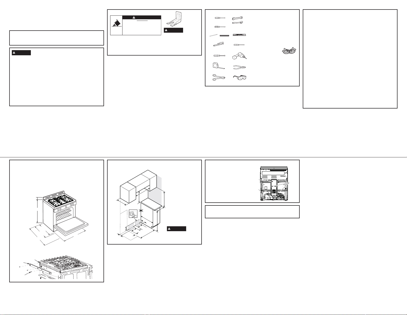
DIMENSIONS AND
CLEARANCES
Provide adequate clearances between the
range and adjacent combustible surfaces.
These dimensions must be met for safe use of
your range.
Allow 30” (76.2 cm) minimum clearance
between burners and bottom of unprotected
wood or metal cabinet, or allow a 24” (61 cm)
minimum when bottom of wood or metal cabinet
is protected by no less than 1/4” (6.4 mm) thick
flame-retardant millboard covered with no less
than No. 28 MSG sheet metal (.015” [.38 mm]
thick), .015” (.38 mm) thick stainless steel, .025”
(0.64 mm) aluminum or .020” (0.5 mm) copper.
Installation of a listed microwave oven or
cooking appliance over the cooktop shall
conform to the installation instructions packed
with that appliance.
For island installation, maintain 2-1/2” minimum
from cutout to back edge of countertop and
3” minimum from cutout to side edges of
countertop.
1 1/8"
36 1/4" ± 1/4
26 7/8"
w/o handle
29 1/2"
w/ handle
47 1/2"
For all installations, install the required rear trim to back of range with 4 screws provided.
Back of
Range
Rear Trim
Screws
30"
DIMENSIONS AND CLEARANCES (CONT.)
GAS PIPE AND ELECTRICAL OUTLET LOCATIONS
30”
Side Wall
18”
Minimum
to cabinets
above counter
6” Right side
6” Left side
Minimum
to side wall
36”
drafts from affecting burner
operation, seal all openings
in floor under appliance and
behind appliance wall.
Max to
cabinets
above
counter
30”
Minimum
16”
Recommended
7 1/2”
2”
Wall-Mounted
Gas
supply
3”
0”
Minimum
to cabinets
below
cooktop
24”
Electrical
supply
2 1/4”
8”
9”
7”
30”
CAUTION
To prevent
CONVERTING TO PROPANE
GAS (OR CONVERTING
BACK TO NATURAL GAS
FROM PROPANE)
This range leaves the factory set for use with
natural gas. If you want to convert to propane
gas, the conversion must be performed by a
qualified propane gas installer.
The conversion orifices and instructions can
be found on back of the range.
Keep these instructions and all orifices in case
you want to convert back to natural gas.
INSTALLATION AT HIGH ALTITUDE
Over 6000ft, product configured for natural gas or propane requires installation of kit (WB28X29254 for natural
gas and WB28X29255 for propane gas). Follow the instructions included with the kit.
Terminal
Block
Cover
Orifice Kit
(location
may vary)
Rear of Range
Screws to
remove
terminal
block cover
INSTALLATION INSTRUCTION
 Loading...