

Page 1

GE Consumer & Industrial
g
Multilin
G650
Generator Protection & Control
System
Instruction manual
GEK-113285A
Firmware version: 3.74
GE Multilin
215 Anderson Avenue
L6E 1B3 Markham, ON -CANADA
T (905) 294 6222 F (905) 294 8512
EnerVista 650 Setup version: 3.76
Copyright © 2008 GE Multilin
GE Multilin
Avda. Pinoa, 10
48170 Zamudio SPAIN
T +34 94 485 88 00 F +34 94 485 88 45
Internet: www.GEMultilin.com
Page 2

TABLE OF CONTENTS
1. GETTING STARTED 1.1 IMPORTANT PROCEDURES
1.1.1 CAUTIONS AND WARNINGS ........................................................................... 1-1
1.1.2 INSPECTION CHECKLIST................................................................................ 1-4
1.1.3 SAFETY INSTRUCTIONS ................................................................................. 1-6
1.2 OVERVIEW
1.2.1 INTRODUCTION TO 650 FAMILY OF RELAYS ............................................... 1-7
1.2.2 HARDWARE ARCHITECTURE......................................................................... 1-7
1.2.3 SOFTWARE ARCHITECTURE.......................................................................... 1-9
1.2.4 COMMUNICATIONS ARCHITECTURE ............................................................ 1-9
1.3 ENERVISTA 650 SETUP SOFTWARE
1.3.1 SYSTEM REQUIREMENTS ............................................................................ 1-11
1.3.2 INSTALLATION................................................................................................ 1-11
1.3.3 CONNECTING ENERVISTA 650 SETUP WITH G650.................................... 1-15
1.4 650 HARDWARE
1.4.1 MOUNTING & WIRING.................................................................................... 1-17
1.4.2 650 COMMUNICATIONS................................................................................. 1-17
1.4.3 FACEPLATE DISPLAY....................................................................................1-18
1.4.4 MAINTENANCE ...............................................................................................1-18
2. PRODUCT DESCRIPTION 2.1 OVERVIEW
2.1.1 G650 OVERVIEW.............................................................................................. 2-1
2.2 SUMMARY
2.2.1 ANSI DEVICE NUMBERS AND FUNCTIONS................................................... 2-3
2.2.2 OTHER DEVICE FUNCTIONS .......................................................................... 2-4
2.3 ORDERING CODE
2.4 TECHNICAL SPECIFICATIONS
2.4.1 PROTECTION ELEMENTS ............................................................................... 2-7
2.4.2 CONTROL........................................................................................................ 2-17
2.4.3 MONITORING.................................................................................................. 2-22
2.4.4 USER-PROGRAMMABLE ELEMENTS...........................................................2-24
2.4.5 METERING ...................................................................................................... 2-25
2.4.6 INPUTS............................................................................................................ 2-26
2.4.7 REAL TIME CLOCK......................................................................................... 2-28
2.4.8 OUTPUTS........................................................................................................ 2-28
2.4.9 CONTROL POWER SUPPLY.......................................................................... 2-29
2.4.10 COMMUNICATIONS........................................................................................2-29
2.4.11 OPTIC FEATURES..........................................................................................2-31
2.4.12 ENVIRONMENTAL CHARACTERISTICS .......................................................2-32
2.4.13 PACKAGING AND WEIGHT............................................................................ 2-32
2.4.14 TYPE TESTS ................................................................................................... 2-32
2.4.15 APPROVALS ...................................................................................................2-32
2.5 EXTERNAL CONNECTIONS
3. HARDWARE 3.1 MODULE DESCRIPTION
3.2 POWER SUPPLY
3.3 MECHANICAL DESCRIPTION
3.3.1 MOUNTING........................................................................................................ 3-3
3.3.2 REAR DESCRIPTION........................................................................................3-6
3.4 WIRING
3.4.1 EXTERNAL CONNECTIONS............................................................................. 3-9
3.4.2 DIGITAL INPUTS WITH TRIP CIRCUIT SUPERVISION ..................................3-9
3.4.3 CABLE/FIBER ETHERNET BOARD................................................................ 3-10
GEK-113285A G650 Generator Protection & Control System 1
Page 3

TABLE OF CONTENTS
3.5 TRANSCEIVER OPTICAL POWER BUDGET VERSUS LINK LENGTH
4. HUMAN INTERFACES.
SETTINGS & ACTUAL
VALUES
4.1 ENERVISTA 650 SETUP SOFTWARE INTERFACE
4.1.1 INTRODUCTION ................................................................................................4-1
4.1.2 ENERVISTA 650 SETUP SOFTWARE OVERVIEW..........................................4-1
4.1.3 MAIN SCREEN...................................................................................................4-3
4.1.4 COMMUNICATION MENU .................................................................................4-4
4.1.5 FILE MANAGEMENT .........................................................................................4-6
4.1.6 ENERVISTA 650 SETUP MENU STRUCTURE...............................................4-10
4.1.7 FILE MENU OVERVIEW ..................................................................................4-11
4.1.8 SETPOINT MENU OVERVIEW........................................................................4-15
4.1.9 ACTUAL VALUES MENU OVERVIEW.............................................................4-23
4.1.10 OPERATIONS MENU OVERVIEW ..................................................................4-26
4.1.11 COMMUNICATION MENU OVERVIEW...........................................................4-27
4.1.12 SECURITY MENU OVERVIEW........................................................................4-30
4.1.13 VIEW MENU OVERVIEW.................................................................................4-30
4.1.14 HELP MENU OVERVIEW ................................................................................4-30
4.2 HUMAN MACHINE INTERFACE (HMI)
4.2.1 DISPLAY...........................................................................................................4-31
4.2.2 FRONT LED INDICATORS ..............................................................................4-32
4.2.3 PUSHBUTTONS...............................................................................................4-32
4.2.4 FRONT PORT AND COVER SEALING SYSTEM............................................4-33
4.2.5 TEXT MENUS...................................................................................................4-34
4.2.6 GRAPHIC DISPLAY .........................................................................................4-52
4.3 WEB SERVER
4.3.1 HOME ...............................................................................................................4-61
4.3.2 SNAPSHOT EVENTS.......................................................................................4-62
4.3.3 CONTROL EVENTS.........................................................................................4-63
4.3.4 ALARMS ...........................................................................................................4-64
4.3.5 OSCILLOGRAPHY...........................................................................................4-65
4.3.6 FAULT REPORT ..............................................................................................4-66
4.3.7 DATA LOGGER................................................................................................4-67
4.3.8 METERING.......................................................................................................4-68
5. SETTINGS 5.1 OVERVIEW
5.1.1 SETTING MAIN MENU.......................................................................................5-1
5.2 PRODUCT SETUP
5.2.1 COMMUNICATION SETTINGS..........................................................................5-3
5.2.2 MODBUS USER MAP ........................................................................................5-6
5.2.3 FAULT REPORT ................................................................................................5-7
5.2.4 OSCILLOGRAPHY.............................................................................................5-9
5.2.5 DATA LOGGER................................................................................................5-12
5.2.6 DEMAND .........................................................................................................5-14
5.3 SYSTEM SETUP
5.3.1 GENERAL SETTINGS......................................................................................5-20
5.3.2 FLEX CURVES.................................................................................................5-20
5.3.3 BREAKER.........................................................................................................5-23
5.3.4 SWITCHGEAR .................................................................................................5-25
5.4 PROTECTION ELEMENTS
5.4.1 CHANGE OF SETTING TABLES IN G650 ELEMENTS ..................................5-26
5.4.2 INVERSE TIME CURVES CHARACTERISTICS..............................................5-30
5.4.3 PHASE CURRENT ...........................................................................................5-40
5.4.4 NEUTRAL CURRENT ......................................................................................5-46
5.4.5 GROUND CURRENT .......................................................................................5-52
5.4.6 RESTRICTED GROUND FAULT (ONLY FOR ENHANCED MODELS) ..........5-56
5.4.7 SENSITIVE GROUND CURRENT (ONLY FOR ENHANCED MODELS) ........5-59
5.4.8 NEGATIVE SEQUENCE CURRENT................................................................5-60
5.4.9 VOLTAGE ELEMENTS ....................................................................................5-63
5.4.10 POWER ............................................................................................................5-71
2 G650 Generator Protection & Control System GEK-113285A
Page 4

TABLE OF CONTENTS
5.5 CONTROL ELEMENTS
5.5.1 SETTING GROUP ........................................................................................... 5-77
5.5.2 UNDERFREQUENCY ELEMENT (81U).......................................................... 5-78
5.5.3 OVERFREQUENCY ELEMENT (81O) ............................................................5-78
5.5.4 SYNCHRONISM CHECK ELEMENT - SYNCHROCHECK (25) ..................... 5-79
5.5.5 BREAKER FAILURE ELEMENT (50BF) (ENHANCED MODELS ONLY) ....... 5-88
5.5.6 VT FUSE FAILURE ELEMENT (VTFF) (ENHANCED MODELS ONLY)......... 5-91
5.5.7 PULSE COUNTERS ........................................................................................ 5-92
5.5.8 ANALOG COMPARATORS............................................................................. 5-94
5.5.9 FREQUENCY RATE OF CHANGE.................................................................. 5-95
5.5.10 LOSS OF MAINS (78V) (FOR ENHANCED MODELS)..................................5-97
5.5.11 LOSS OF EXCITATION (40)...........................................................................5-99
5.5.12 ACCIDENTAL ENERGIZATION (50/27)........................................................ 5-101
5.6 INPUTS/OUTPUTS
5.6.1 INPUT/OUTPUT PLACEMENT......................................................................5-103
5.6.2 CONTROL SETTINGS FOR INPUTS/OUTPUTS.......................................... 5-104
5.6.3 INPUTS.......................................................................................................... 5-106
5.6.4 OUTPUTS...................................................................................................... 5-108
5.6.5 CIRCUIT SUPERVISION AND CONTACT SEAL-IN CIRCUITS ................... 5-110
5.6.6 ANALOG BOARDS SPECIFIC SETTINGS ................................................... 5-120
5.6.7 VIRTUAL INPUTS.......................................................................................... 5-120
5.6.8 VIRTUAL OUTPUTS...................................................................................... 5-121
5.7 TESTING
5.7.1 FORCE IO–INPUT TESTING ........................................................................ 5-122
5.7.2 FORCE IO–OUTPUT TESTING .................................................................... 5-122
5.8 RELAY CONFIGURATION
5.8.1 OUTPUTS...................................................................................................... 5-123
5.8.2 LEDS..............................................................................................................5-125
5.8.3 OPERATIONS................................................................................................5-126
5.8.4 PROTECTION ELEMENTS ........................................................................... 5-130
5.8.5 OSCILLOGRAPHY ........................................................................................ 5-132
5.8.6 CONTROL EVENTS ...................................................................................... 5-133
5.8.7 SWITCHGEAR .............................................................................................. 5-135
5.8.8 HMI (HUMAN-MACHINE INTERFACE).........................................................5-137
5.9 LOGIC CONFIGURATION (PLC EDITOR)
5.9.1 INTRODUCTION............................................................................................5-141
5.9.2 THEORY OF OPERATION............................................................................ 5-142
5.9.3 MAIN MENU................................................................................................... 5-145
5.9.4 CONFIGURATION GENERATION ................................................................5-146
5.9.5 GENERATION OF LIBRARIES ..................................................................... 5-147
5.9.6 EXAMPLE OF APPLICATION ....................................................................... 5-148
6. ACTUAL VALUES 6.1 FRONT PANEL
6.1.1 LEDS..................................................................................................................6-1
6.2 STATUS
6.2.1 OPERATION BITS .............................................................................................6-2
6.2.2 BREAKER.......................................................................................................... 6-2
6.2.3 PROTECTION.................................................................................................... 6-3
6.2.4 CONTROL ELEMENTS ................................................................................... 6-12
6.2.5 PROTECTION SUMMARY .............................................................................. 6-19
6.2.6 SNAPSHOT EVENTS SUMMARY...................................................................6-22
6.2.7 MODBUS USER MAP......................................................................................6-24
6.2.8 SWITCHGEAR STATUS..................................................................................6-24
6.2.9 CALIBRATION ................................................................................................. 6-25
6.2.10 FLEX CURVES ................................................................................................6-27
6.2.11 SYSTEM INFO................................................................................................. 6-27
6.2.12 RECORD STATUS .......................................................................................... 6-27
6.3 METERING
6.3.1 PRIMARY VALUES..........................................................................................6-32
6.3.2 SECONDARY VALUES ................................................................................... 6-36
6.3.3 PHASOR DIAGRAM ........................................................................................ 6-38
GEK-113285A G650 Generator Protection & Control System 3
Page 5

TABLE OF CONTENTS
6.3.4 FREQUENCY ...................................................................................................6-38
6.4 INPUTS / OUTPUTS
6.4.1 CONTACT INPUTS ..........................................................................................6-39
6.4.2 CONTACT OUTPUT STATUS..........................................................................6-40
6.4.3 CONTACT OUTPUT OPERATES....................................................................6-40
6.4.4 CONTACT OUTPUT RESETS .........................................................................6-41
6.4.5 I/O BOARD STATUS ........................................................................................6-42
6.4.6 VIRTUAL INPUTS ............................................................................................6-42
6.4.7 VIRTUAL OUTPUTS ........................................................................................6-42
6.4.8 ANALOG INPUTS.............................................................................................6-43
6.5 RECORDS
6.5.1 EVENT RECORDER ........................................................................................6-44
6.5.2 WAVEFORM CAPTURE ..................................................................................6-46
6.5.3 FAULT REPORT ..............................................................................................6-47
6.5.4 DATA LOGGER................................................................................................6-48
7. SECURITY 7.1 ADDING USERS
7.1.1 USER RIGHTS ...................................................................................................7-1
7.2 CHANGING PASSWORDS
7.3 ENABLING SECURITY
7.4 LOGING INTO ENERVISTA 650 SETUP
8. BOOTCODE AND
FIRMWARE UPGRADE
8.1 INTRODUCTION
8.1.1 COMMUNICATION PARAMETERS...................................................................8-2
8.2 BOOT CODE UPGRADE
8.3 FIRMWARE VERSION UPGRADE
8.3.1 FIRMWARE UPGRADE .....................................................................................8-9
8.3.2 BOOT CODE UPGRADE (*).............................................................................8-11
8.3.3 FIRMWARE UPGRADE (*)...............................................................................8-12
9. COMMISSIONING 9.1 VISUAL INSPECTION
9.2 GENERAL CONSIDERATIONS ON THE POWER SUPPLY NETWORK
9.3 ISOLATION TESTS
9.4 INDICATORS
9.5 POWER SUPPLY TESTING
9.6 COMMUNICATIONS
9.7 VERIFICATION OF MEASUREMENT
9.7.1 VOLTAGES ........................................................................................................9-7
9.7.2 PHASE CURRENTS...........................................................................................9-7
9.7.3 ACTIVE, REACTIVE POWER, AND COSJ METERING....................................9-8
9.7.4 FREQUENCY .....................................................................................................9-8
9.8 INPUTS AND OUTPUTS
9.8.1 DIGITAL INPUTS................................................................................................9-9
9.8.2 CONTACT OUTPUTS ......................................................................................9-10
9.8.3 CIRCUIT CONTINUITY SUPERVISION INPUTS ............................................9-10
9.8.4 LATCHING CIRCUITS......................................................................................9-10
4 G650 Generator Protection & Control System GEK-113285A
Page 6

TABLE OF CONTENTS
9.9 CONNECTIONS FOR TESTING PROTECTION ELEMENTS
9.10 INSTANTANEOUS OVERCURRENT (50PH, 50N, 50G Y 50SG)
9.11 TIME OVERCURRENT (51PH, 51PL, 51N, 51G)
9.12 DIRECTIONAL ELEMENTS (67N, 67G)
9.12.1 67N ELEMENT................................................................................................. 9-14
9.12.2 67G ELEMENT ................................................................................................ 9-15
9.13 UNDERVOLTAGE ELEMENTS (27P, 27X)
9.13.1 27P ELEMENT................................................................................................. 9-16
9.13.2 27X ELEMENT................................................................................................. 9-16
9.14 OVERVOLTAGE ELEMENTS (59P, 59X, 59NH)
9.14.1 59P ELEMENT................................................................................................. 9-17
9.14.2 59X ELEMENT................................................................................................. 9-17
9.14.3 59NH ELEMENT..............................................................................................9-18
9.14.4 47 ELEMENT - NEG SEQ OV ......................................................................... 9-19
9.15 FREQUENCY ELEMENTS (81O/81U)
10. APPLICATION EXAMPLES 10.1 EXAMPLE 1: COMMUNICATION & PROTECTION SETTINGS
PROCEDURE
10.1.1 DESCRIPTION OF THE EXERCISE ...............................................................10-1
10.1.2 PROCEDURE TO COMMUNICATE WITH THE RELAY................................. 10-1
10.1.3 PROCEDURE TO SET THE PROTECTION FUNCTION ................................ 10-3
10.1.4 TEST ................................................................................................................ 10-4
10.2 EXAMPLE 2: PROCEDURE TO SET AN OPERATION
10.2.1 DESCRIPTION OF THE EXERCISE ...............................................................10-5
10.2.2 PROCEDURE ................................................................................................. 10-5
10.2.3 TEST ................................................................................................................ 10-7
11. FREQUENTLY ASKED
QUESTIONS
11.1 COMMUNICATIONS
11.2 PROTECTION
11.3 CONTROL AND HMI
11.4 RELAY CONFIGURATION
12. G650TROUBLESHOOTING
12.1 SYMPTOMS AND RECOMMENDED ACTIONS
GUIDE
A. LOGIC OPERANDS A.1 LOGIC OPERANDS
B. MODBUS PROTOCOL B.1 ACCESS TO G650 DATA
B.2 MODBUS G650
B.2.1 FUNCTIONS USED ...........................................................................................B-2
B.2.2 PHYSICAL LAYER.............................................................................................B-2
B.2.3 DATA LINK LAYER............................................................................................B-3
B.2.4 GENERIC READING .........................................................................................B-4
B.2.5 GENERIC WRITING ..........................................................................................B-5
B.2.6 FUNCTION CODES ..........................................................................................B-6
B.2.7 EXCEPTIONS AND ERROR RESPONDS ........................................................B-6
GEK-113285A G650 Generator Protection & Control System 5
Page 7

TABLE OF CONTENTS
B.3 DATA TYPE
B.4 MODBUS APPENDIX
B.4.1 DATA MANAGEMENT ...................................................................................... B-8
B.4.2 WRITING SETTINGS ........................................................................................B-8
B.4.3 SNAPSHOT EVENTS........................................................................................ B-8
B.4.4 OPERATIONS .................................................................................................B-12
B.5 OUTPUT WRITING
B.5.1 CONTROL EVENTS........................................................................................ B-14
B.5.2 EVENT STRUCTURE...................................................................................... B-15
B.6 EVENTS STATUS REQUEST(ALARMS)
B.6.1 CONTROL EVENTS RETRIEVAL FROM THE COMMAND LINE ................. B-17
B.6.2 SERIAL COMUNICATION...............................................................................B-17
B.6.3 ETHERNET COMMUNICATION ..................................................................... B-17
B.6.4 ACKNOWLEDGEMENT OF EVENTS (ALARMS)...........................................B-18
B.6.5 VIRTUAL INPUTS WRITING........................................................................... B-18
B.6.6 USER MAP ......................................................................................................B-18
B.6.7 RETRIEVING OSCILOGRAPHY ..................................................................... B-19
B.6.8 TIME SYNCHRONIZATION ............................................................................ B-19
B.6.9 ENQUEUEING MESSAGES .......................................................................... B-20
B.6.10 TRACES AND TROUBLESHOOTING.............................................................B-20
B.6.11 MODBUS CHECK FUNCTION........................................................................ B-21
B.7 MEMORY MAP
C. DNP 3.0 PROTOCOL FOR
G650
C.1 DNP 3.0 PROTOCOL SETTINGS
C.2 DNP 3.0 DEVICE PROFILE DOCUMENT
C.3 IMPLEMENTATION TABLE
C.4 BINARY INPUT POINTS
C.5 DNP CONFIGURATION EXAMPLES
C.5.1 CONFIGURING DNP USER MAP................................................................... C-11
C.5.2 EXAMPLE OF CUSTOM BINARY INPUT POINTS MAP................................C-13
C.5.3 MULTIPLE DNP 3.0 MASTERS COMMUNICATION WITH G650 .................. C-15
C.6 BINARY OUTPUT AND CONTROL RELAY OUTPUT
C.7 BINARY COUNTERS
C.8 ANALOG INPUTS
D. IEC 60870-5-104 PROTOCOL D.1 INTRODUCTION
D.2 TECHNICAL DESCRIPTION
D.3 BASIC APPLICATION FUNCTIONS
D.4 IEC 104 SETTINGS
D.5 IEC 60870-5-104 POINT LIST
E. FACTORY DEFAULT LOGIC E.1 FACTORY DEFAULT LOGIC
F. FACTORY DEFAULT
CONFIGURATION
F.1 FACTORY DEFAULT SETTINGS
F.2 FACTORY DEFAULT CONFIGURATION
6 G650 Generator Protection & Control System GEK-113285A
Page 8

TABLE OF CONTENTS
G. MISCELLANEOUS G.1 GE MULTILIN WARRANTY
GEK-113285A G650 Generator Protection & Control System 7
Page 9

TABLE OF CONTENTS
8 G650 Generator Protection & Control System GEK-113285A
Page 10
1 GETTING STARTED 1.1 IMPORTANT PROCEDURES
1 GETTING STARTED 1.1IMPORTANT PROCEDURES 1.1.1 CAUTIONS AND WARNINGS
To help ensure years of trouble free operation, please read through the following chapter for information to help guide you
through the initial installation procedures of your new relay.
BEFORE ATTEMPTING TO INSTALL OR USE THE RELAY, IT IS IMPERATIVE THAT ALL WARNINGS AND CAUTIONS
IN THIS MANUAL ARE REVIEWED TO HELP PREVENT PERSONAL INJURY, EQUIPMENT DAMAGE, AND/OR
DOWNTIME.
CAUTION: THE OPERATOR OF THIS INSTRUMENT IS ADVISED THAT IF THE EQUIPMENT IS USED IN A MANNER
NOT SPECIFIED IN THIS MANUAL, THE PROTECTION PROVIDED BY THE EQUIPMENT MAY BE IMPAIRED.
1
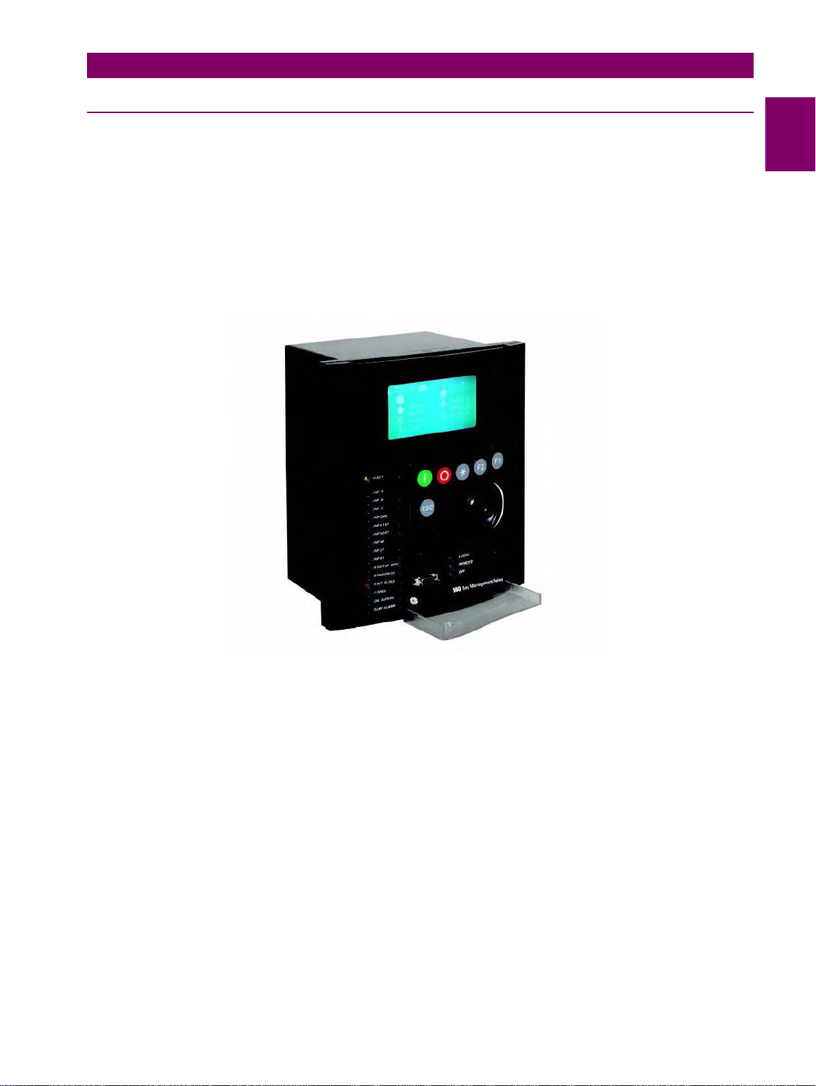
Figure 1–1: FRONT VIEW OF G650 UNITS
GEK-113285A G650 Generator Protection & Control System 1-1
Page 11
1.1 IMPORTANT PROCEDURES 1 GETTING STARTED
1.1.1.1 COMMUNICATION BOARDS WITHDRAWAL / INSERTION
WARNING: MODULE WITHDRAWAL AND INSERTION SHALL ONLY BE PERFORMED BY DULY QUALIFIED
SERVICE PERSONNEL. FOR PERSONAL SECURITY PURPOSES, BEFORE ACCOMPLISHING ANY
WITHDRAWAL OR INSERTION OPERATION, THE RELAY MUST BE POWERED OFF AND ALL THE REAR
TERMINALS MUST BE POTENTIAL FREE. THE RELAY MUST BE GROUNDED USING THE REAR GROUNDING
SCREW.
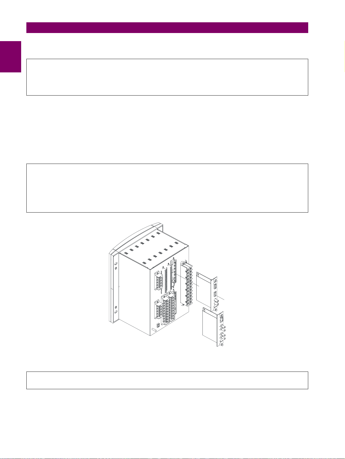
The modular design of the relay allows for the withdrawal and insertion of the communication module.
Figure 1–2: shows the location of communication modules on the rear part of the relay. Qualified personnel must carry out
the insertion or extraction of the communication boards only after interrupting the relay auxiliary voltage and ensuring that
all the rear terminals are potential free.
Communication boards are installed on the rear of the unit, the upper port being reserved for the asynchronous
communications board and CAN, and the lower port for the ETHERNET board in any of its configurations.
Before performing any of these actions, control power must be removed fro m the relay and all the r ear terminals
must be potential free. A grounded antistatic wristband must be used when manipulating the module in order to avoid
electrostatic discharges that may cause damage to the electronic components.
WITHDRAWAL: Loosen the small screws that keep the faceplate in place and extract the module.
INSERTION: Insert the module and press it firmly in the case, until it is completely fixed. After this, bolt the faceplate
screws and replace the control power. Check that the relay is fully operative.
Figure 1–2: MODULE WITHDRAWAL/INSERTION
GE Multilin will not be responsible for any damage of the relay, connected equipment or personnel whenever
these safety rules are not followed.
1-2 G650 Generator Protection & Control System GEK-113285A
Page 12
1 GETTING STARTED 1.1 IMPORTANT PROCEDURES
1.1.1.2 MAGNETIC MODULE TERMINALS
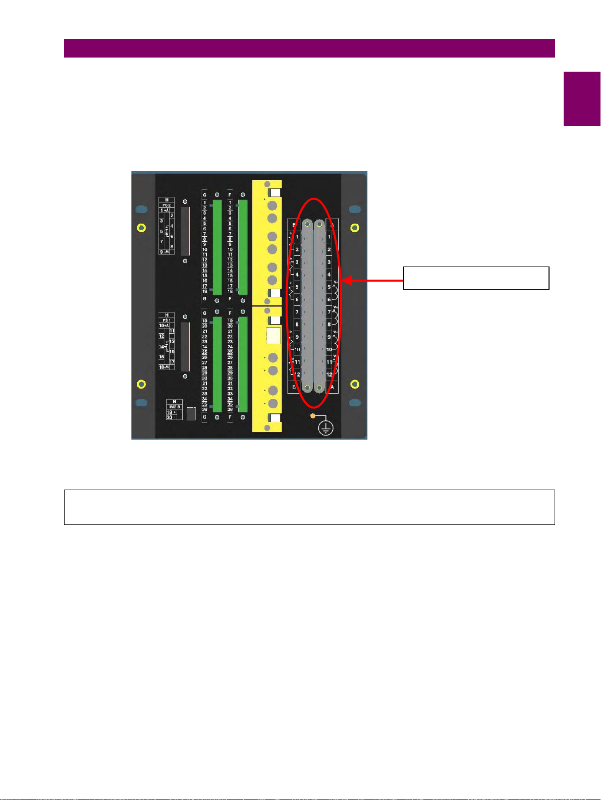
The transformer module for the VTs and CTs is already connected to a female connector screwed to the case. The
current inputs incorporate shorting bars, so that the module can be extracted without the need to short-circuit the
currents externally. It is very important, for safety reasons not to change or switch the terminals for CTs and VTs.
AC Input Terminals
1
GE Multilin
Figure 1–3: REAR VIEW OF G650 UNIT
will not be responsible for any damage of the relay, connected equipment or personnel
whenever these safety rules are not followed.
GEK-113285A G650 Generator Protection & Control System 1-3
Page 13
1.1 IMPORTANT PROCEDURES 1 GETTING STARTED
1.1.2 INSPECTION CHECKLIST
Unwrap the relay and inspect the relay for physical damage.
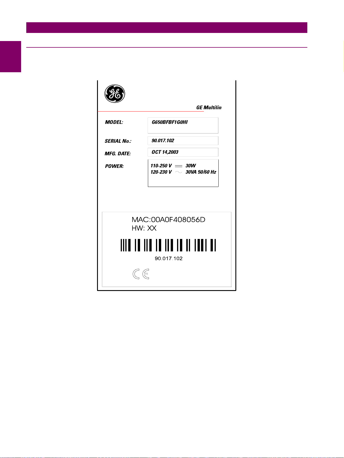
Verify that the model on the label on the side of the relay matches the model ordered.
Figure 1–4: IDENTIFICATION LABEL (A4454P30)
Please ensure that you received the following items with your relay:
• Mounting screws for fixing the relay to a cabinet
• CD containing EnerVista 650 Setup software
• Wiring diagram
• Certificate of Compliance
1-4 G650 Generator Protection & Control System GEK-113285A
Page 14

1 GETTING STARTED 1.1 IMPORTANT PROCEDURES
For product information, instruction manual updates, and the latest software updates, please visit the GE Multilin Home
Page www.geindustrial.com/multilin
Note: If there is any physical damage detected on the relay, or any of the contents listed are missing, please
contact GE Multilin immediately at:
.
EUROPE, MIDDLE EAST AND AFRICA:
GE MULTILIN
Av. Pi noa, 10
48170 Zamudio, Vizcaya (SPAIN)
Tel.: (34) 94-485 88 54, Fax: (34) 94-485 88 38
E-mail: [email protected]
AMERICA, ASIA AND AUSTRALIA:
GE MULTILIN
215, Anderson Avenue
L6E 1B3 Markham, ON (CANADA)
Tel.: +1 905 294 6222, Fax: +1 905 201 2098
E-mail: [email protected]
1
The information provided herein is not intended to cover all the details of the variations of the equipment, nor does
it take into account the circumstances that may be present in your installation, operating or maintenance
activities.
Should you wish to receive additional information, or for any particular problem that cannot be solved by referring
to the information contained herein, please contact GENERAL ELECTRIC MULTILIN.
GEK-113285A G650 Generator Protection & Control System 1-5
Page 15

1.1 IMPORTANT PROCEDURES 1 GETTING STARTED
1.1.3 SAFETY INSTRUCTIONS
The G650 ground screw shown in Figure 1–5: must be correctly grounded.
Figure 1–5: LOCATION OF GROUNDING SCREW
Before communicating with a G650 unit through the front serial port, please ensure that the computer is grounded.
In case of using a laptop, it is recommended not to have it connected to its power supply. In many cases it might not be
correctly grounded either due to the power supply or to the connector cables used.
This is required not only for personal protection, bu t also to avoid a potential voltage difference between the
relay’s serial port and the computer’s port, which could produce permanent damage to the computer or the relay.
GE Multilin will not be responsible for any damage to the relay or connected equipment whenever this elemental
safety rule is not followed.
1-6 G650 Generator Protection & Control System GEK-113285A
Page 16

1 GETTING STARTED 1.2 OVERVIEW
1.2OVERVIEW 1.2.1 INTRODUCTION TO 650 FAMILY OF RELAYS
Historically, substation protection, control and metering functions were performed with electromechanical equipment. This
first generation of equipment was gradually replaced by analog electronic equipment (called static devices), most of which
emulated the single-function approach of their electromechanical precursors. Both of these technologies required
expensive cabling and auxiliary equipment to produce functioning systems.
Recently, digital electronic equipment has begun to provide protection, control and metering functions. Initially, this
equipment was either single function or had very limited multi-function capability, and did not significantly reduce the
cabling and auxiliary equipment required. However, recent digital relays have become quite multi-functional, reducing
cabling and auxiliaries significantly. These devices also transfer data to central control facilities and Human Machine
Interfaces using electronic communications. The functions performed by these products have become so broad that many
users prefer the term IED (Intelligent Electronic Device).
It is obvious to station designers that the amount of cabling and auxiliary equipment installed in stations can be even further
reduced, to 20% to 70% of the levels common in 1990, to achieve large cost reductions. This requires placing even more
functions within the IEDs.
Users of power equipment are also interested in reducing cost by improving power quality and personnel productivity, and
as always, in increasing system reliability and efficiency. These objectives are realized through software which is used to
perform functions at both the station and supervisory levels. The use of these systems is growing rapidly.
High speed communications are required to meet the data transfer rates required by modern automatic control and
monitoring systems. In the near future, very high speed communications will be required to perform protection signalling.
IEDs with capabilities outlined above will also provided significantly more power system data than is presently available,
enhance operations and maintenance, and permit the use of adaptive system configuration for protection and control
systems. This new generation of equipment must also be easily incorporated into automation systems, at both the station
and enterprise levels.
1
1.2.2 HARDWARE ARCHITECTURE
650 family of relays has been designed to meet the goals described above that are appearing nowadays in the environment
of new substations.
The 650 is a digital-based device containing a central processing unit (CPU) that handles multiple types of input and output
signals. The 650 family can communicate over a local area network (LAN) with an operator interface, a programming
device, or another 650 or UR device.
The CPU module contains firmware that provides protection elements in the form of logic algorithms, as well as
programming logic gates, timers, and latches for control features. It incorporates two internal processors, one for generic
use and a second one dedicated for communications.
Input Elements accept a variety of analog or digital signals from the field. The 650 isolates and converts these signals into
logic signals used by the relay.
Output Elements convert and isolate the logic signals generated by the relay into digital signals that can be used to control
field devices.
GEK-113285A G650 Generator Protection & Control System 1-7
Page 17
1.2 OVERVIEW 1 GETTING STARTED
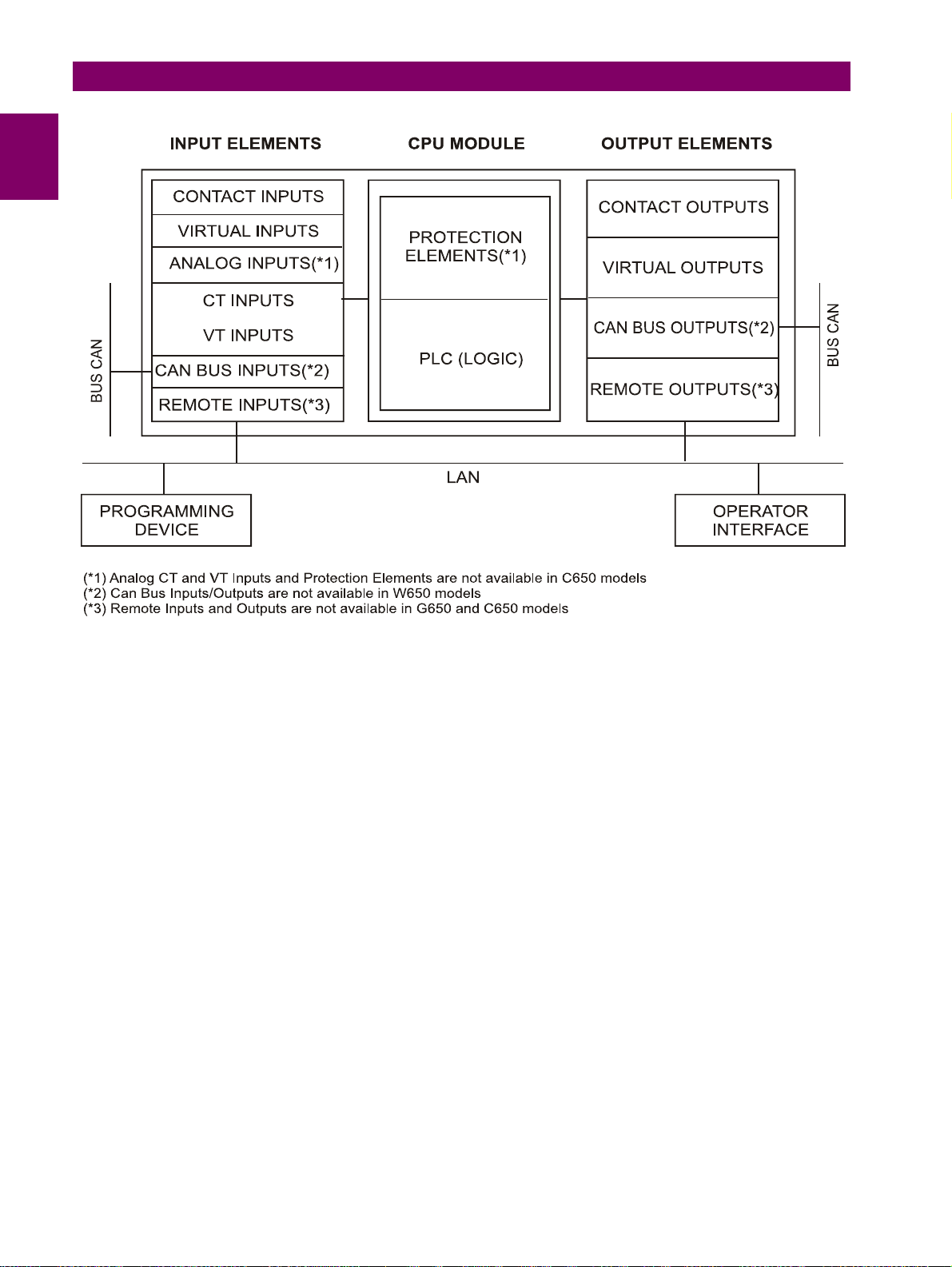
Figure 1–6: 650 CONCEPT BLOCK DIAGRAM
Contact Inputs/Outputs are signals associated to the physical input/output contacts in the relay
CT and VT inputs are signals coming from the inputs of current and voltage transformers, used for monitoring the power
system signals. Not available for C650 models.
CAN Bus Inputs/Outputs: are signals associated to physical input/output contacts from independent modules connected
to the 650 unit via a CAN Bus. Not available for W650 models.
PLC: Programmable Logic Controller. Control module that enables the unit configuration (assignment of inputs/outputs)
and the implementation of logic circuits.
Protection Elements: Relay protection elements, for example: Overcurrent, overvoltage, etc. Not available for C650
models.
Remote inputs and outputs provide a means of sharing digital point state information between remote devices using IEC
61850 GSSE and GOOSE messages.Remote I/O are not available for G650 models. Not available for G650 and C650
models.
Analog Inputs are signals associated with transducers.
1-8 G650 Generator Protection & Control System GEK-113285A
Page 18
1 GETTING STARTED 1.2 OVERVIEW
1.2.3 SOFTWARE ARCHITECTURE
The firmware (software embedded in the relay) has been designed using object oriented programming techniques (OOP).
These techniques are based on the use of objects and classes, and provide the software architecture with the same
characteristics as the hardware architecture, i.e., modularity, scalability and flexibility.
1.2.4 COMMUNICATIONS ARCHITECTURE
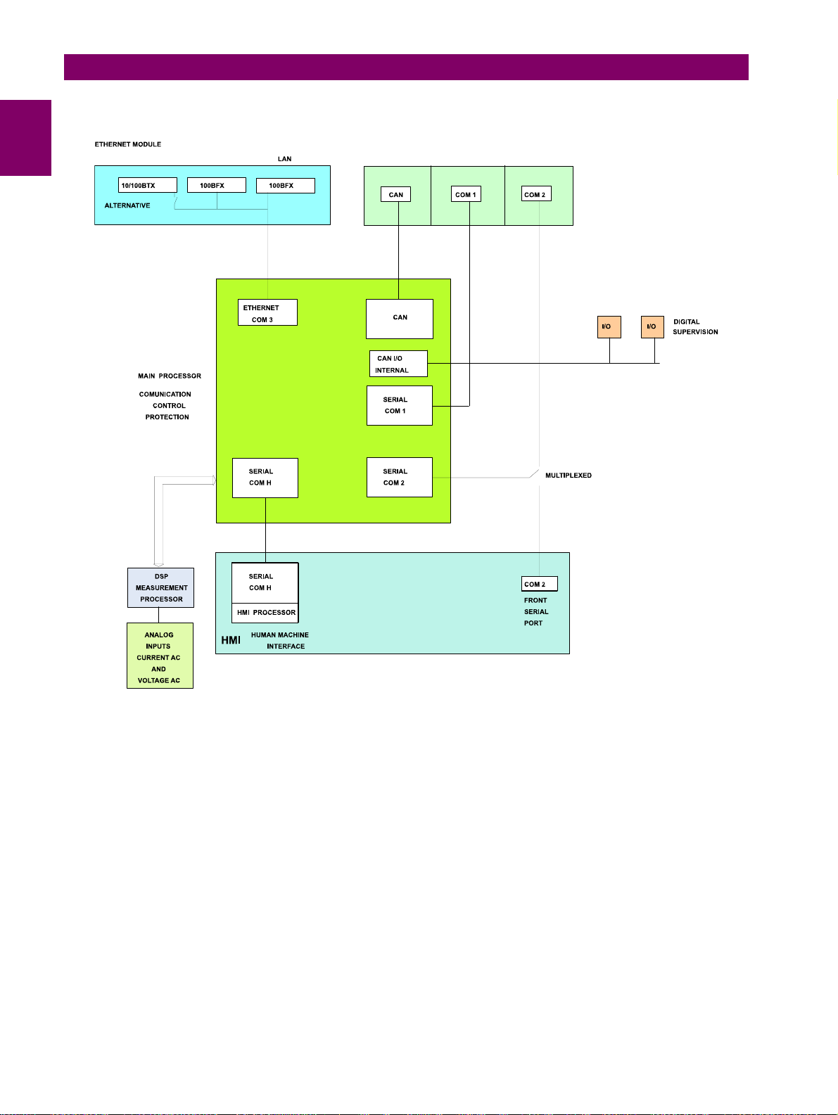
The main processor performs protection, control, and communication functions, incorporating two internal processors, one
for generic use and a second one dedicated for communications.
A dedicated serial port is used for communication between the main processor and the human-machine interface. The
serial connection provides great immunity against electromagnetic disturbances, thus increasing system safety.
All G650 units incorporate an RS232 serial port on the front of the relay. There is also a possibility to incorporate up to two
additional communication modules on the rear.
One of the modules provides asynchronous serial communications, using different physical media (RS485, plastic or glass
fiber optic) depending on the selected model. The module incorporates two identical ports, COM1 and COM2. The COM2
port is multiplexed with the front port. Additionally, this module may incorporate a port for CAN BUS communications, used
for the connection to the Remote CAN BUS I/O module. This feature allows increasing up to 100% the I/O capability, when
the maximum number of I/Os available inside the relay is not enough for a specific application.
Available options are:
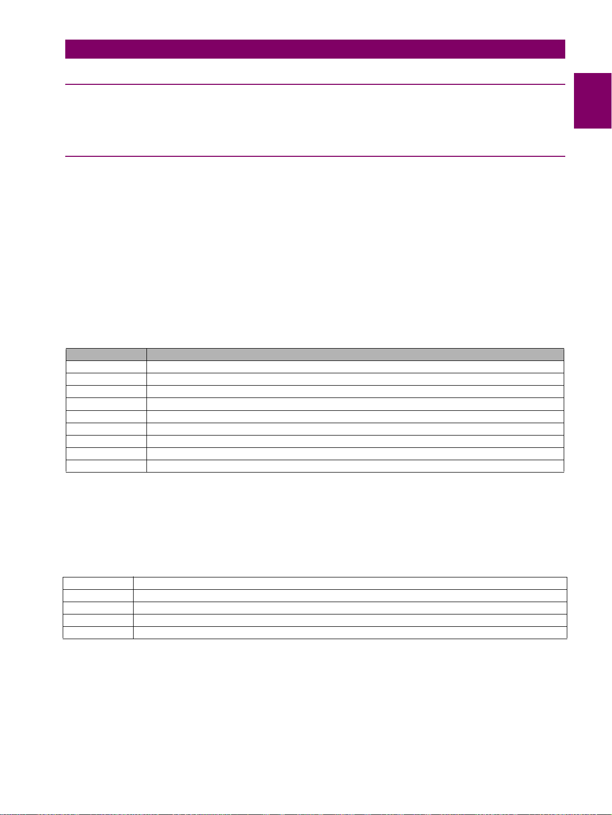
Table 1–1: REAR SERIAL COMMUNICATIONS BOARD 1
BOARD CODE FUNCTIONALITY
F Without additional communication ports
A Two RS485 ports
P Two Plastic F.O. ports
G Two Glass F.O. ports
X Two RS485 ports and a CAN port for remote CAN Bus Inputs/Outputs
Y Two Plastic F.O. ports and a CAN port for remote CAN Bus Inputs/Outputs (fiber)
Z Two Glass F.O. ports and a CAN port for remote CAN Bus Inputs/Outputs (fiber)
C CAN port for remote CAN Bus I/O (cable)
M RS485 CAN port for remote CAN bus I/O (cable)
1
The other module provides Ethernet communications (COM3 port), using 10/100BaseTX (self-negotiable speed) or
100BaseFX connectors, depending on the selected model. The most complete models include a double redundant
100BaseFX fiber optic port. Redundancy is provided at the physical level; the unit incorporates internally duplicated and
independent controllers for extended system reliability and accessibility.
Available Options are:
Table 1–2: REAR ETHERNET COMMUNICATIONS BOARD 2
BOARD CODE FUNCTIONALITY
B One 10/100BaseTX port (self-negotiable speed)
C One 10/100BaseTX port and one 100BaseFX port.
D One 10/100BaseTX port and redundant 100BaseFX ports
E Redundant 10/100BaseTX ports
For options C and D it is required to select the active physical media, by means of an internal selector inside the module.
The factory configuration for this selection is the 10/100BaseTX port.
Finally, internal communication with input and output modules is performed via an internal CAN bus, independent from the
one used for remote CAN BUS I/Os. This fact provides increased communication speed, as well as the possibility of
acknowledgement of modules, abnormalities, etc. As this is a serial port supporting a communications protocol, it provides
extraordinary immunity against external or internal disturbances.
GEK-113285A G650 Generator Protection & Control System 1-9
Page 19
1.2 OVERVIEW 1 GETTING STARTED
Figure 1–7: COMMUNICATIONS ARCHITECTURE (B6816F1)
1-10 G650 Generator Protection & Control System GEK-113285A
Page 20
1 GETTING STARTED 1.3 ENERVISTA 650 SETUP SOFTWARE
1.3ENERVISTA 650 SETUP SOFTWARE 1.3.1 SYSTEM REQUIREMENTS
The EnerVista 650 Setup software interface is the preferred method to edit settings and view actual values because the PC
monitor can display more information in a simple comprehensible format.
The following minimum requirements must be met for the EnerVista 650 Setup software to properly operate on a PC:
• Pentium® class or higher processor (Pentium® II 300 MHz or higher recommended)
• Windows® NT 4.0 (Service Pack 3 or higher), Windows® 2000, Windows® XP
• Internet Explorer® 5.0 or higher
• 64 MB of RAM (128 MB recommended)
• 40 MB of available space on system drive and 40 MB of available space on installation drive
• RS232C serial and/or Ethernet port for communications to the relay
1.3.2 INSTALLATION
After ensuring the minimum requirements for using EnerVista 650 Setup are met (see previous section), use the following
procedure to install the EnerVista 650 Setup from the GE EnerVista CD.
1. Insert the GE EnerVista CD into your CD-ROM drive.
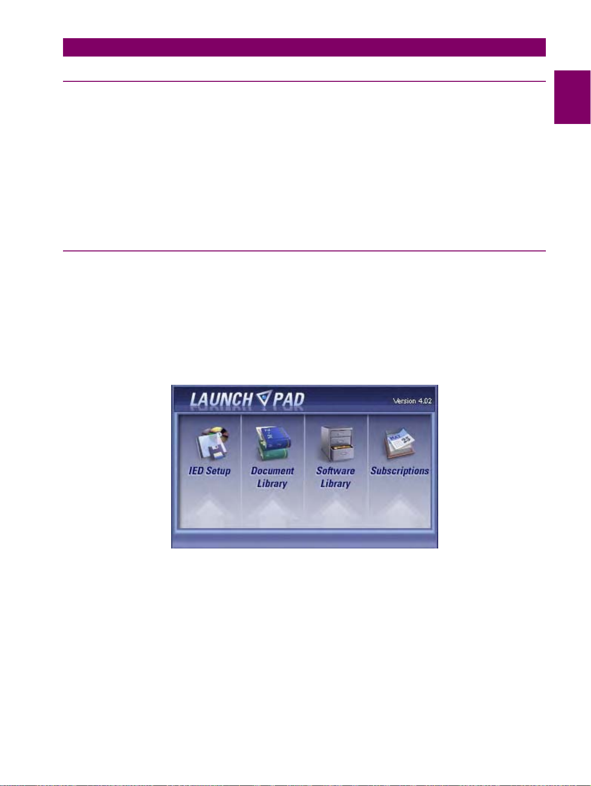
2. Click the Install Now button and follow the installation instructions to install the no-charge EnerVista software.
3. When installation is complete, start the EnerVista Launchpad application.
4. Click the IED Setup section of the Launch Pad window.
1
Figure 1–8: LAUNCHPAD WINDOW
GEK-113285A G650 Generator Protection & Control System 1-11
Page 21

1.3 ENERVISTA 650 SETUP SOFTWARE 1 GETTING STARTED
5. In the EnerVista Launch Pad window, click the Add Product button and select the “G650 Generator Protection &
Control System” relay from the Install Software window as shown below. Select the “Web” option to ensure the most
recent software release, or select “CD” if you do not have a web connection, then click the Add Now button to list
software items for the G650.
Figure 1–9: ADD PRODUCT WINDOW
6. If “Web” option is selected, choose the G650 software program and release notes (if desired) from the list and click the
Download Now button to obtain the installation program.
Figure 1–10: WEB UPGRADE WINDOW
1-12 G650 Generator Protection & Control System GEK-113285A
Page 22

1 GETTING STARTED 1.3 ENERVISTA 650 SETUP SOFTWARE
7. EnerVista Launchpad will obtain the installation program from the Web or CD. Once the download is complete, double-
click the installation program to install the EnerVista 650 Setup software.
8. Select the complete path, including the new directory name, where the EnerVista 650 Setup will be installed.
9. Click on Next to begin the installation. The files will be installed in the directory indicated and the installation program
will automatically create icons and add EnerVista 650 Setup to the Windows start menu.
10. Follow the on-screen instructions to install the EnerVista 650 Setup software. When the Welcome window appears,
click on Next to continue with the installation procedure.
1
Figure 1–11: ENERVISTA 650 SETUP INSTALLATION
11. When the Choose Destination Location window appears, and if the software is not to be located in the default
directory, click Change… and type in the complete path name including the new directory name and click Next to
continue with the installation procedure.
Figure 1–12: ENERVISTA 650 SETUP INSTALLATION CONT.
GEK-113285A G650 Generator Protection & Control System 1-13
Page 23

1.3 ENERVISTA 650 SETUP SOFTWARE 1 GETTING STARTED
12. The default program group where the application will be added to is shown in the Selected Progra m Folder window.
Click Next to begin the installation process, and all the necessary program files will be copied into the chosen directory.
Figure 1–13: SELECT PROGRAM FOLDER
13. To finish with the installation process, select the desired language for startup.
Figure 1–14: LANGUAGE WINDOW
1-14 G650 Generator Protection & Control System GEK-113285A
Page 24

1 GETTING STARTED 1.3 ENERVISTA 650 SETUP SOFTWARE
14. Click Finish to end the installation. The G650 device will be added to the list of installed IEDs in the EnerVista
Launchpad window, as shown below.
1
Figure 1–15: ENERVISTA LAUNCHPAD
1.3.3 CONNECTING ENERVISTA 650 SETUP WITH G650
This section is intended as a quick start guide to using the EnerVista 650 Setup software. Please refer to section 4.1 in this
manual for more information about the EnerVista 650 Setup software interface.
a) CONFIGURING AN ETHERNET CONNECTION
Before starting, verify that the Ethernet network cable is properly connected to the Ethernet port on the back of the relay.
1. Install and start the latest version of the EnerVista 650 Setup software (available from the GE EnerVista CD or online
from http://www.GEindustrial.com/multilin (see previous section for installation instructions).
2. Go to “Communication>Computer” and enter the following data referring to communications:
3. Select Control Type as MODBUS TCP/IP from the drop-down list. This option will display a number of interface
parameters that must be entered for proper Ethernet communications.
4. Enter the relay IP address (from “Setpoint>Product Setup >Communication Settings>Network>IP ADDRESS”) in
the IP Address field in MODBUS TCP/IP SETUP.
5. Enter the relay ModBus address (from “Setpoint>Product Setup >Communication Settings>ModBus
Protocol>ModBus Address COM1/COM2 setting”) in the Unit Identifier (Slave Address) field.
6. Enter the ModBus port address (from “Setpoint>Product Setup >Communication Settings>ModBus
Protocol>ModBus Port Number” setting) in the ModBus Port field.
7. The Device has now been configured for Ethernet communications. Proceed to press the ON button to begin
communicating.
GEK-113285A G650 Generator Protection & Control System 1-15
Page 25

1.3 ENERVISTA 650 SETUP SOFTWARE 1 GETTING STARTED
b) CONFIGURING AN RS232 CONNECTION
Before starting, verify that the RS232 serial cable is properly connected to the RS232 port on the front panel of the relay.
1. Install and start the latest version of the EnerVista 650 Setup software (available from the GE EnerVista CD or online
from http://www.GEindustrial.com/multilin (see previous section for installation instructions).
2. Go to “Communication>Computer” and enter the following data referred to communications:
3. Select Control Type as No Control Type from the drop-down list. This option will display a number of interface
parameters that must be entered for proper serial communications.
4. Enter the relay Slave Address (“Setpoint>Product Setup >Communication Settings>ModBus Protocol” menu) in
the Slave Address field. The default value is 254.
5. Enter the physical communications parameters (Baudrate and parity settings) from the “Setpoint>Product Setup
>Communication Settings>Serial Ports” menu, in their respective fields. Default values are 19200 for baudrate and
none for parity.
6. The Device has now been configured for RS232 communications. Proceed to press the ON button to begin
communicating.
1-16 G650 Generator Protection & Control System GEK-113285A
Page 26

1 GETTING STARTED 1.4 650 HARDWARE
1.4650 HARDWARE 1.4.1 MOUNTING & WIRING
Please refer to Chapter 3. Hardware for detailed mounting and wiring instructions.
1.4.2 650 COMMUNICATIONS
The Enervista 650 Setup software communicates to the relay via the faceplate RS232 port or the rear RS485/Ethernet
ports. To communicate via the faceplate RS232 port, a standard “straight-through” serial cable is used. The DB-9 male end
is connected to the relay and the DB-9 or DB-25 female end is connected to the PC COM1 or COM2 port as described in
Figure 1–16:.
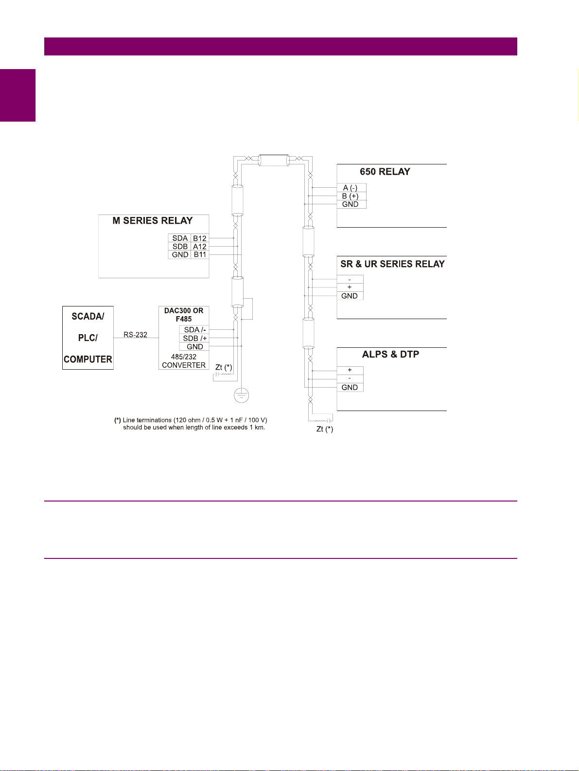
To communicate through the G650 rear RS485 port from a PC RS232 port, the GE Multilin RS232/RS485 converter box is
required. This device (catalog number F485) connects to the computer using a “straight-through” serial cable. A shielded
twisted-pair (20, 22 or 24 AWG according to American standards; 0.25, 0.34 or 0.5 mm2 according to European standards)
connects the F485 converter to the G650 rear communication port.
In order to minimize communication errors that could be caused by external noise, it is recommended to use a shielded
twist pair. In order to avoid loops where external currents could flow, the cable shield must be grounded only at one end.
The converter box (-, +, GND) terminals are connected to the relay (SDA, SDB, GND) terminals respectively. For long
communications cables (longer than 1 km), the RS485 circuit must be terminated in an RC network (i.e. 120 ohm, 1 nF).
This circuit is shown on Figure 1–17: RS485 CONNECTION FOR 650 UNITS, associated to text Zt(*).
1
Figure 1–16: RELAY- PC CONNECTION FOR RS232 FRONT PORT
To minimize errors from noise, the use of shielded twisted pair wire is recommended. For correct operation, polarity must
be respected, although a different polarity will not damage the unit. For instance, the relays must be connected with all
RS485 SDA terminals connected together, and all SDB terminals connected together. This may result confusing
sometimes, as the RS485 standard refers only to terminals named “A” and “B”, although many devices use terminals
named “+” and “-“.
As a general rule, terminals “A” should be connected to terminals “-“, and terminals “B” to “+”. The GND terminal should be
connected to the common wire inside the shield, when provided. Otherwise, it should be connected to the shield. Each
relay should also be daisy chained to the next one in the link. A maximum of 32 relays can be connected in this manner
GEK-113285A G650 Generator Protection & Control System 1-17
Page 27
1.4 650 HARDWARE 1 GETTING STARTED
without exceeding driver capability. For larger systems, additional serial channels must be added. It is also possible to use
commercially available repeaters to increase the number of relays on a single channel to more than 32. Do not use other
connection configurations different to the recommended.
Lightening strikes and ground surge currents can cause large momentary voltage differences between remote ends of the
communication link. For this reason, surge protection devices are internally provided. To ensure maximum reliability, all
equipment should have similar transient protection devices installed.
Figure 1–17: RS485 CONNECTION FOR 650 UNITS
To communicate through the G650 rear Ethernet port from a PC a crossover cable is required. If the connection is
performed through a hub or a switch, a direct Ethernet cable is required.
1.4.3 FACEPLATE DISPLAY
All messages are displayed on a 20x4 character LCD display. An optional graphic display is also available. Messages are
displayed in different languages according to selected model.
1.4.4 MAINTENANCE
G650 requires a minimum amount of maintenance when it is commissioned into service. G650 is a microprocessor based
relay and its characteristics do not change over time. As such no further functional tests are required. However, it is
recommended that maintenance on the G650 be scheduled with other system maintenance. The maintenance may involve
the following:
In-service maintenance:
1. Visual verification of the analog values integrity such as voltage and current (in comparison to other devices on the
corresponding system).
2. Visual verification of active alarms, relay display messages and LED indications.
3. Visual inspection for any damage, corrosion, dust or loose wires.
1-18 G650 Generator Protection & Control System GEK-113285A
Page 28

1 GETTING STARTED 1.4 650 HARDWARE
4. Event recorder file download with further event analysis.
Out-of-service maintenance:
1. Check wiring connections for firmness.
2. Analog values (current, voltages, analog inputs) injection test and metering accuracy verification. Calibrated test
equipment is required.
3. Protection elements setpoints verification (analog values injection or visual verification of setting file entries against
relay settings schedule).
4. Contact inputs and outputs verification. This test can be conducted by direct change of state forcing or as part of the
system functional testing.
5. Visual inspection for any damage, corrosion or dust.
6. Event recorder file download with further events analysis.
Unscheduled maintenance such as during a disturbance causing system interruption:
1. View the event recorder and oscillography or fault report for correct operation of inputs, outputs and elements.
If it is concluded that the relay or one of its modules is of concern, contact GE Multilin or one of its representative for prompt
service.
1
GEK-113285A G650 Generator Protection & Control System 1-19
Page 29

1.4 650 HARDWARE 1 GETTING STARTED
1-20 G650 Generator Protection & Control System GEK-113285A
Page 30

2 PRODUCT DESCRIPTION 2.1 OVERVIEW
2 PRODUCT DESCRIPTION 2.1OVERVIEW 2.1.1 G650 OVERVIEW
The G650 is a machine generator protection and control device. It may be used to protect and control reciprocating
machines, as well as to operate as a packaged generator sets mains failure detector. Generally speaking the G650
provides distributed generation management capabilities.
The main features of G650 devices include:
• Protection relay with control capabilities for protection of small and medium generators.
• Replacement for legacy devices in the long term based on improved and open protocols in communications as well as
orientation to machine protection system rather than individual protection functions.
• Based on the 650 platform.
• Full graphic capabilities in large display with control functions and PLC programming.
• Protection elements repeated in three groups, used as independent groups or all elements at the same time.
2
Figure 2–1: G650 BLOCK DIAGRAM FOR BASIC FUNCTIONALITY MODELS
GEK-113285A G650 Generator Protection & Control System 2-1
Page 31
2.1 OVERVIEW 2 PRODUCT DESCRIPTION
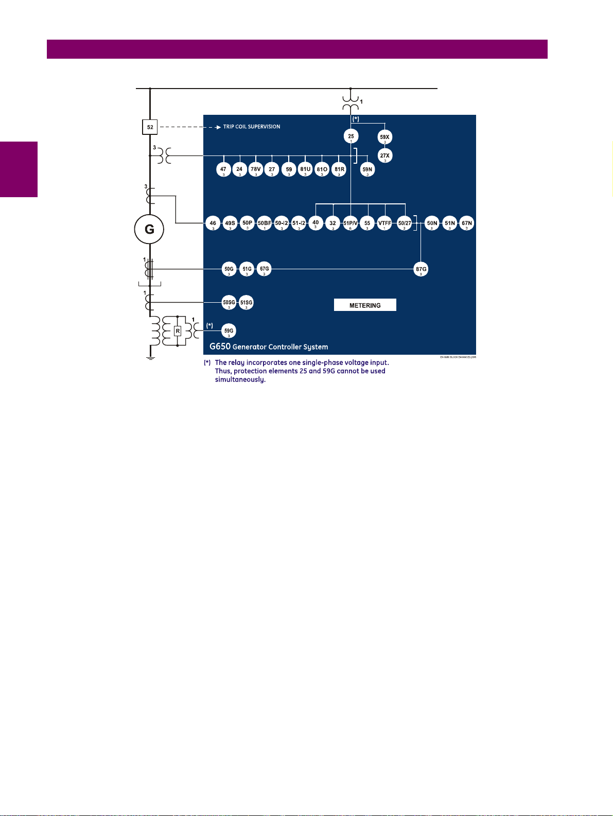
Figure 2–2: G650 BLOCK DIAGRAM FOR ENHANCED FUNCTIONALITY MODELS
2-2 G650 Generator Protection & Control System GEK-113285A
Page 32

2 PRODUCT DESCRIPTION 2.2 SUMMARY
2.2SUMMARY 2.2.1 ANSI DEVICE NUMBERS AND FUNCTIONS
DEVICE NUMBER FUNCTION
24 Volt/Hertz (only enhanced model)
25 Synchronism Check
27P Phase Undervoltage
27X Auxiliary Undervoltage
32DIR Directional Power
40 Loss of Excitation
46 Generator Unbalance
47 Negative Sequence Overvoltage
49S Generator thermal model
50/27 Inadvertent Generator Energization
50-2/51-2 Negative Sequence IOC/TOC
50BF Breaker Failure (only enhanced model)
50G
50N Neutral Instantaneous Overcurrent (calculated from the phase currents)
50P Phase Instantaneous Overcurrent
51G
51N Neutral Time Overcurrent (calculated from the phase currents)
51P/V Voltage Restraint Overcurrent
50SG/51SG Sensitive Ground Fault (only enhanced model)
55 Power Factor Limiting (Only enhanced model)
59N Neutral Overvoltage
59P Phase Overvoltage
59X Auxiliary Overvoltage
59G Ground Overvoltage
67N Neutral directional
67G Ground Directional
78V Phase shift / Loss of mains (only enhanced model)
810 Overfrequency
81U Underfrequency
81R Frequency Rate of Change
87G Restricted Ground Fault (only enhanced model)
VTFF VT Fuse Failure (only enhanced model)
Ground Instantaneous Overcurrent (measured from 4
Ground Time Overcurrent (measured from 4
th
th
current transformer)
current transformer)
2
GEK-113285A G650 Generator Protection & Control System 2-3
Page 33
2.2 SUMMARY 2 PRODUCT DESCRIPTION
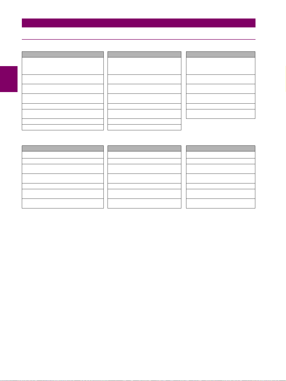
2.2.2 OTHER DEVICE FUNCTIONS
INPUTS/OUTPUTS METERING COMMUNICATIONS
9 Analog Inputs: 5 current inputs (3 for phases,
1 for ground, 1 for sensitive ground), 4 voltage
inputs (3 for phases, 1 for busbar or auxiliary
voltage)
Digital Programmable Contact Inputs (up to 64) Voltages phase to phase and phase to
Digital Programmable Contact Outputs (up to
16)
32 Latched Virtual Inputs
32 Self-Reset Virtual Inputs
Virtual Outputs (up to 512) Frequency ModBus User Map
Tripping and closing circuit supervision Sequence components of currents and
Analog Inputs (dCmA) Pulse Counters
USER INTERFACE RECORDS OTHERS
Alphanumerical display (4x20) Data Logger
Graphic display (16 x 40) Demand Breaker Control
User Programmable LEDs (15) Event Recorder (up to 128 configurable
User Programmable Keys (up to 5) Fault Locator and Fault report (up to 10
Easy menu management thanks to shuttle key Oscillography (up to 20 records) Settings Groups (up to )
Configurable One-Line Diagram (Graphic
model only)
Phasor Diagram (available in EnerVista 650
Setup)
Metering Current for phases, ground and
sensitive ground inputs
ground
Real, Reactive and Apparent Power and
Power Factor
Three Phase Energy IEC 870-5-104
voltages
Analog Comparators
events)
records)
Snapshot Events (up to 479) Operations (up to 24)
Front RS232 port, Two rear RS485/
fibre optic ports, 10/100 TX and 100 FX
Mbps Ethernet port
ModBus Communications RTU and
over TCP/IP
DNP Multimaster (3.0 Level 2)
2
Breaking Arcing Current (I
IRIG-B synchronization/SNTP
Logic Equations (PLC Editor)
Web Server Application
t)
2-4 G650 Generator Protection & Control System GEK-113285A
Page 34
2 PRODUCT DESCRIPTION 2.3 ORDERING CODE
2.3ORDERING CODE
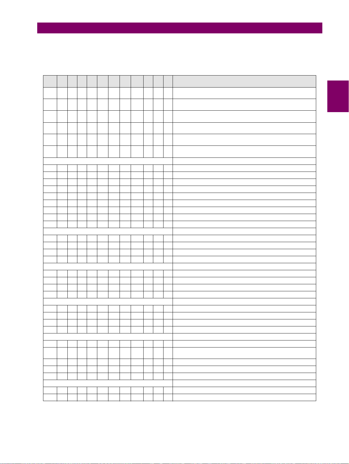
G650 units are supplied as ½ 19” rack, 6 units high, containing the following modules: power supply, CPU, I/O modules,
communication modules. The required information to completely define an G650 model is shown on Table 2–1:
Table 2–1: ORDERING CODE
G650- - - F - G - - - - - DESCRIPTION
B Basic Display (4x20 characters) and basic protection functionality
M Graphic Display (240x128 pixels) with Standard Symbols and basic
N Graphic Display with IEC symbols (240x128 pixels) and basic
E Basic Display (4x20 characters) and enhanced protection
C Graphic Display (240x128 pixels) with Standard Symbols and
D Graphic Display with IEC symbols (240x128 pixels) and enhanced
F None
A Redundant RS485
P Redundant plastic fiber optic
G Redundant glass fiber optic
X Redundant RS485 + fiber remote CAN bus I/O
Y Redundant plastic fiber optic + fiber remote CAN bus I/O
Z Redundant glass fiber optic + fiber remote CAN bus I/O
C Cable Remote CAN Bus I/O
M RS485 + cable Remote CAN Bus I/O
B 10/100 Base TX
C 10/100 Base TX + 100 Base FX
D 10/100 Base TX + Redundant 100 Base FX
E Redundant 10/100 Base TX
1 16 Digital Inputs + 8 Outputs
2 8 Digital Inputs + 8 Outputs + 2 trip/close circuit supervision circuits
4 32 Digital Inputs
5 16 Digital Inputs + 8 Analog Inputs
0 None
1 16 Digital Inputs + 8 Outputs
4 32 Digital Inputs (see Note 1)
5 16 Digital Inputs + 8 Analog Inputs (See Note 1)
LO 24-48 Vdc (range 19.2 – 57.6)
HI
LOR Redundant LO
HIR Redundant HI
Notes:
(1) The digit selected for option G must be equal or higher than the digit selected for option F for models including boards 4 and 5.
(see Note 2)
protection functionality (see Note 2)
protection functionality (see Note 2)
functionality (see Note 2)
enhanced protection functionality (see Note 2)
protection functionality (see Note 2)
REAR SERIAL COMMUNICATIONS BOARD 1
REAR ETHERNET COMMUNICATIONS BOARD 2
I/O BOARD IN SLOT F
I/O BOARD IN SLOT G
AUXILIARY VOLTAGE
110-250 Vdc (range 88 – 300)
120-230 Vac (range 96 – 250)
5 Procome, Modbus® RTU,TCP/IP
ENVIRONMENTAL PROTECTION
- Without Harsh (Chemical) Environment Conformal Coating
H Harsh (Chemical) Environment Conformal Coating
2
GEK-113285A G650 Generator Protection & Control System 2-5
Page 35

2.3 ORDERING CODE 2 PRODUCT DESCRIPTION
F1G5 is a valid selection and F5G1 is and invalid selection.
(2) The Protection functionality description for basic and enhanced models is listed in section 2.2.1: ANSI DEVICE NUMBERS AND
FUNCTIONS on page 2–3.
2-6 G650 Generator Protection & Control System GEK-113285A
Page 36

2 PRODUCT DESCRIPTION 2.4 TECHNICAL SPECIFICATIONS
2.4 TECHNICAL SPECIFICATIONS
NOTE: TECHNICAL SPECIFICA TIONS ARE SUBJECT TO CHANGE WITHOUT NOTICE
2.4.1 PROTECTION ELEMENTS
Phase and ground units use as operation magnitude the current value received by the unit in current inputs, while the
neutral unit uses the calculated current value from the three phase currents.
The isolated ground unit will be used only for those applications where the neutral is completely isolated, and it uses the
fifth CT of the unit. This CT has a sensitivity that is 10 times higher than the universal model (connected to 1A or 5A
transformers). Therefore, it does not admit such a high permanent overload.
2.4.1.1 PHASE TIME OVERCURRENT (51PH/51PL)
Current Input Phasor (without harmonics) or RMS
Rated current For connection to 1 or 5 A CTs.
Pickup level 0.05 to 160.00 A in steps of 0.01 A
Dropout level 97% to 98% of the pickup level
Level Accuracy
Curve Shapes IEEE extremely / very / moderately inverse
Curve Multiplier (Time Dial) 0.00 to 900.00 s in steps of 0.01 s
Reset type Instantaneous or time delayed according to IEEE
Timing accuracy Operate at > 1.03 times the pickup ±3% of operate time or
Voltage restraint Selectable by setting
Saturation Level 48 times the pickup level
Snapshot Events Selectable by setting
Values at nominal frequency:
±0.5% of the reading ± 10 mA from 0.05 to 10 A
±1.5% of the reading for higher values.
IEC A/B/C/long-time inverse/short time inverse curve
IAC extremely / very / moderately inverse
ANSI extremely / very / normally / moderately inverse
2
t
I
Definite time
Rectifier curve
FlexCurve™ A/B/C/D user curve
50 ms. (whichever is greater)
2
GEK-113285A G650 Generator Protection & Control System 2-7
Page 37

2.4 TECHNICAL SPECIFICATIONS 2 PRODUCT DESCRIPTION
2.4.1.2 GROUND TIME OVERCURRENT (51G)
Current Input Phasor (without harmonics) or RMS
Rated current For connection to 1 or 5 A CTs.
Pickup level 0.05 to 160.00 A in steps of 0.01 A
Dropout level 97% to 98% of the pickup level
Level Accuracy
Values at nominal frequency:
±0.5% of the reading ± 10 mA from 0.05 to 10 A
±1.5% of the reading for higher values.
Curve Shapes IEEE extremely / very / moderately inverse
IEC A/B/C/long-time inverse/short time inverse curve
IAC extremely / very / moderately inverse
ANSI extremely / very / normally / moderately inverse
2
t
I
Definite time
Rectifier curve
FlexCurve™ A/B/C/D user curve
Curve Multiplier (Time Dial) 0.00 to 900.00 s in steps of 0.01 s
Reset type Instantaneous or time delayed according to IEEE
Timing accuracy Operate at > 1.03 times the pickup ±3% of operate time or
50 ms. (whichever is greater)
Saturation Level 48 times the pickup level
Snapshot Events Selectable by setting
2.4.1.3 NEUTRAL TIME OVERCURRENT (51N)
Current Input Fundamental Phasor (without harmonics)
Pickup level 0.05 to 160.00 A in steps of 0.01 A
Dropout level 97% to 98% of the pickup level
Level Accuracy
Values at nominal frequency:
±0.5% of the reading ± 10 mA from 0.05 to 10 A
±1.5% of the reading for higher values.
Curve Shapes IEEE extremely / very / moderately inverse
IEC A/B/C/long-time inverse/short time inverse curve
IAC extremely / very / moderately inverse
ANSI extremely / very / normally / moderately inverse
I2t
Definite time
Rectifier curve
FlexCurve™ A/B/C/D user curve
Curve Multiplier (Time Dial) 0.00 to 900.00 s in steps of 0.01 s
Reset type Instantaneous or time delayed according to IEEE
Timing accuracy Operate at > 1.03 times the pickup ±3% of operate time or
50 ms. (whichever is greater)
Saturation Level 48 times the pickup level
Snapshot Events Selectable by setting
2-8 G650 Generator Protection & Control System GEK-113285A
Page 38

2 PRODUCT DESCRIPTION 2.4 TECHNICAL SPECIFICATIONS
2.4.1.4 SENSITIVE GROUND TIME OVERCURRENT (51SG)
Current Input Phasor (without harmonics) or RMS
Rated current For connection to 1 or 5 A CTs.
Pickup level 0.005 to 16.000 A in steps of 0.001 A
Dropout level 97% to 98% of the pickup level
Level Accuracy
Curve Shapes IEEE extremely / very / moderately inverse
Curve Multiplier (Time Dial) 0.00 to 900.00 s in steps of 0.01 s
Reset type Instantaneous or time delayed according to IEEE
Timing accuracy Operate at > 1.03 times the pickup ±3% of operate time
Saturation Level 48 times the pickup level
Snapshot Events Selectable by setting
Values at nominal frequency:
±1.5% of the reading ± 1 mA from 0.005 to 16 A
IEC A/B/C/long-time inverse/short time inverse curve
IAC extremely / very / moderately inverse
ANSI extremely / very / normally / moderately inverse
I2t
Definite time
Rectifier curve
FlexCurve™ A/B/C/D user curve
or 50 ms. (whichever is greater)
2
2.4.1.5 PHASE AND GROUND INSTANTANEOUS OVERCURRENT (50PH50G)
Current Input Phasor (without harmonics) or RMS
Rated current For connection to 1 or 5 A CTs.
Pickup level 0.05 to 160.00 A in steps of 0.01 A
Dropout level 97% to 98% of the pickup level
Level Accuracy
Overreach < 2%
Trip delay 0.00 to 900.00 s. in steps of 0.01 s.
Reset delay 0.00 to 900.00 s. in steps of 0.01 s.
Operate time <50 ms at 3 x Pickup at 50 Hz, typically
Timing accuracy at 0 ms time delay (no intentional delay): 50ms
Snapshot Events Selectable by setting
Values at nominal frequency:
±0.5% of the reading ± 10 mA from 0.05 to 10 A
±1.5% of the reading for higher values
at non-zero time delay: ±3% of operate time or 50 ms
(whichever is greater)
GEK-113285A G650 Generator Protection & Control System 2-9
Page 39

2.4 TECHNICAL SPECIFICATIONS 2 PRODUCT DESCRIPTION
2.4.1.6 NEUTRAL INSTANTANEOUS OVERCURRENT (50N)
Current Input Fundamental Phasor (without harmonics)
Pickup level 0.05 to 160.00 A in steps of 0.01 A
Dropout level 97% to 98% of the pickup level
Level Accuracy
Overreach < 2%
Trip delay 0.00 to 900.00 s. in steps of 0.01 s.
Reset delay 0.00 to 900.00 s. in steps of 0.01 s.
Operate time <50 ms at 3 x Pickup at 50 Hz, typically
Timing accuracy at 0 ms time delay (no intentional delay): 50ms
Snapshot Events Selectable by setting
2.4.1.7 SENSITIVE GROUND INSTANTANEOUS OVERCURRENT (50SG)
Current Input Phasor (without harmonics) or RMS
Rated current For connection to 1 or 5 A CTs.
Pickup level 0.005 to 16.000 A in steps of 0.001 A
Dropout level 97% to 98% of the pickup level
Level Accuracy
Overreach < 2%
Trip delay 0.00 to 900.00 s. in steps of 0.01 s.
Reset delay 0.00 to 900.00 s. in steps of 0.01 s.
Operate time <50 ms at 3 x Pickup at 50 Hz, typically
Timing accuracy at 0 ms time delay (no intentional delay): 50ms
Snapshot Events Selectable by setting
Values at nominal frequency:
±0.5% of the reading ± 10 mA from 0.05 to 10 A
±1.5% of the reading for higher values
at non-zero time delay: ±3% of operate time or 50 ms
(whichever is greater)
Values at nominal frequency:
±1.5% of the reading ± 1 mA from 0.005 to 16 A
at non-zero time delay: ±3% of operate time or 50 ms
(whichever is greater)
2.4.1.8 NEGATIVE SEQUENCE TIME OVERCURRENT (51-2)
Current Input Fundamental Phasor (without harmonics)
Pickup level 0.05 to 160.0 A in steps of 0.01 A
Dropout level 97% to 98% of the pickup level
Level Accuracy
2-10 G650 Generator Protection & Control System GEK-113285A
Values at nominal frequency:
±0.5% of the reading ± 10 mA from 0.05 to 10 A
±1.5% of the reading for higher values
Page 40

2 PRODUCT DESCRIPTION 2.4 TECHNICAL SPECIFICATIONS
Curve Shapes IEEE extremely / very / moderately inverse
IEC A/B/C/long-time inverse/short time inverse curve
IAC extremely / very / moderately inverse
ANSI extremely / very / normally / moderately inverse
I2t
Definite time
Rectifier curve
FlexCurve™ A/B/C/D user curve
Curve Multiplier (Time Dial) 0.00 to 900.00 s in steps of 0.01 s
Reset type Instantaneous or time delayed according to IEEE
Timing accuracy Operate at > 1.03 times the pickup ±3% of operate time
or 50 ms. (whichever is greater)
Saturation Level 48 times the pickup level
Snapshot Events Selectable by setting
2.4.1.9 NEGATIVE SEQUENCE INSTANTANEOUS OVERCURRENT (50-2)
Current Input Fundamental Phasor (without harmonics)
Rated current For connection to 1 or 5 A CTs.
Pickup level 0.05 to 160.00 A in steps of 0.01 A
Dropout level 97% to 98 % of the pickup level
Level Accuracy Values at nominal frequency
±0.5% of the reading ± 10 mA from 0.1 to 10 A
±1.5% of the reading for higher values
Trip delay 0.00 to 900.00 s. in steps of 0.01 s.
Reset delay 0.00 to 900.00 s. in steps of 0.01 s.
Operate time 50 ms at 3 x Pickup at 50 Hz, typically
Timing accuracy Operate at 1.00 times the pickup ±3% of operate time or
50 ms. (whichever is greater)
Snapshot Events Selectable by setting
2
GEK-113285A G650 Generator Protection & Control System 2-11
Page 41

2.4 TECHNICAL SPECIFICATIONS 2 PRODUCT DESCRIPTION
2.4.1.10 GENERATOR UNBALANCE (46)
Gen. nominal current 0.00 to 10.00 A in steps of 0.01 A (rated full load
current of the machine
Stages 2 (
(I2t with linear reset and definite time))
)
Pickup level 0.00 to 100.00% in steps of 0.01
Dropout level 97% to 98 % of the pickup level
Level Accuracy Values at nominal frequency
±0.5% of the reading ± 10 mA from 0.1 to 10 A
±1.5% of the reading for higher values
Time dial (K-value) 0.00 to 100.00 in steps of 0.01
Pickup delay 0.0 to 1000.0 s in steps of 0.1
Reset delay 0.0 to 1000.0 s in steps of 0.1
Operate time <50 ms at 50 Hz, typically
Timing accuracy ±3% of operate time or 50 ms. (whichever is greater)
Snapshot Events Selectable by setting
2.4.1.11 GROUND DIRECTIONAL (67G)
Directionality Forward and reverse selectable by setting
Polarizing Voltage, current, dual
Polarizing Voltage V
Polarizing Current
Operating Current
(measured or calculated, selected by setting)
N
th
Isg (measured from 5
current transformer)
Ig (measured from 4th current transformer)
Polarizing Voltage threshold 0 to 00 Vac in steps of 1 V
Polarizing Current threshold 0.005 A
Characteristic angle -90º to +90º in steps of 1º
Block Logic Permission or Block selectable by setting
Angle accuracy
±2º for I>0.1 A and V>5 Vac
Operate time <30ms, typically
2.4.1.12 NEUTRAL DIRECTIONAL (67N)
Directionality Forward and reverse selectable by setting
Polarizing Voltage, current, dual
Polarizing Voltage V
Polarizing Current
Operating Current I
(measured or calculated, selected by setting)
N
th
Isg (measured from 5
N
current transformer)
Polarizing Voltage threshold 0 to 00 Vac in steps of 1 V
Polarizing Current threshold 0.005 A
Characteristic angle -90º to +90º in steps of 1º
Block Logic Permission or Block selectable by setting
Angle accuracy
±2º for I>0.1 A and V>5 Vac
Operate time <30ms, typically
2-12 G650 Generator Protection & Control System GEK-113285A
Page 42

2 PRODUCT DESCRIPTION 2.4 TECHNICAL SPECIFICATIONS
2.4.1.13 GENERATOR THERMAL MODEL (49S)
Current Input Fundamental Phasor (without harmonics)
Rated current For connection to 1 or 5 A CTs.
Pickup level 0.05 to 160.0 A in steps of 0.01 A
Dropout level 97% to 98% of the pickup level
Level Accuracy
Timing accuracy ±3.5% of operate time or 50 ms. (whichever is greater)
Heating constant 3.0 to 600.0 minutes in steps of 0.1 minute
Cooling constant 1.00 to 6.00 times the heating constant in steps of 0.01
K1 constant 0.0 to 8.0 in steps of 0.1 (Negative sequence influence)
Snapshot Events Selectable by setting
2.4.1.14 RESTRICTED GROUND FAULT (87G)
Values at nominal frequency:
±0.5% of the reading ± 10 mA from 0.05 to 10 A
±1.5% of the reading for higher values
2
Pickup level
Dropout level 97% to 98 % of the pickup level
Slope 0.00 to 100.00 % in steps of 0.01%
Trip delay
Operate time <50 ms at 50 Hz, typically
Timing accuracy ±3% of operate time or 50 ms. (whichever is greater)
Snapshot Events Selectable by setting
2.4.1.15 PHASE OVERVOLTAGE (59P)
Voltage Input Fundamental Phasor (without harmonics) of phase-to-
Pickup level 3 to 500 in steps of 1 V
Dropout level 97% to 98% of the pickup level
Level Accuracy
Trip delay 0.00 to 900.00 s. in steps of 0.01 s.
Reset delay 0.00 to 900.00 s. in steps of 0.01 s.
Timing accuracy ±3.5% of operate time or 50 ms. (whichever is greater)
Logic Any/Two/All phases logic selectable by setting
Snapshot Events Selectable by setting
0.02 to 20.00 in units of Phase CT Primary in steps of
0.01
0.00 to 600.00 s in steps of 0.01 s
phase voltages
±1% reading ±0.1% Full Scale from 10 to 500 V at
nominal frequency
GEK-113285A G650 Generator Protection & Control System 2-13
Page 43

2.4 TECHNICAL SPECIFICATIONS 2 PRODUCT DESCRIPTION
2.4.1.16 PHASE UNDERVOLTAGE (27P)
Voltage Input Fundamental Phasor of phase-to-ground or phase-to-
phase voltages (selectable by setting)
Pickup level 3 to 500 in steps of 1 V
Dropout level 102% to 103% of the pickup level
Level accuracy
Curve Shapes Fixed time or inverse curve
Reset type Instantaneous
Curve Multiplier (Time Dial) 0.00 to 900.00 s. in steps of 0.01 s.
Timing accuracy ±3.5% of operate time or 50 ms. (whichever is greater)
Minimum Voltage Threshold 0 to 500 in steps of 1 V
Logic Any/Two/All phases logic selectable by setting
Supervised by Breaker Selectable by setting
Snapshot Events Selectable by setting
2.4.1.17 NEUTRAL OVERVOLTAGE (59NH)
±1% reading ±0.1% Full Scale from 10 to 500 V at
nominal frequency
Voltage Input Fundamental Phasor of the neutral voltage (calculated
from phases)
Pickup level 3 to 500 in steps of 1 V
Dropout level 97% to 98% of the pickup level
Level accuracy
Trip delay 0.00 to 900.00 s. in steps of 0.01 s
Reset delay 0.00 to 900.00 s. in steps of 0.01 s
Timing accuracy ±3.5% of operate time or 50 ms. (whichever is greater)
Snapshot Events Selectable by setting
2.4.1.18 GROUND OVERVOLTAGE (59G)
Voltage Input Fundamental Phasor of the ground voltage (measured
Pickup level 3 to 500 in steps of 1 V
Dropout level 97% to 98% of the pickup level
Level accuracy
Trip delay 0.00 to 900.00 s. in steps of 0.01 s
Reset delay 0.00 to 900.00 s. in steps of 0.01 s
Timing accuracy ±3.5% of operate time or 50 ms. (whichever is greater)
Snapshot Events Selectable by setting
±1% reading ±0.1% Full Scale from 10 to 500 V at
nominal frequency
from 4th voltage transformer)
±1% reading ±0.1% Full Scale from 10 to 500 V at
nominal frequency
2-14 G650 Generator Protection & Control System GEK-113285A
Page 44

2 PRODUCT DESCRIPTION 2.4 TECHNICAL SPECIFICATIONS
2.4.1.19 AUXILIARY OVERVOLTAGE (59X)
Voltage Input Fundamental Phasor of the auxiliary voltage
Pickup level 3 to 500 in steps of 1 V
Dropout level 97% to 98% of the pickup level
Level accuracy
Trip delay 0.00 to 900.00 s. in steps of 0.01 s
Reset delay 0.00 to 900.00 s. in steps of 0.01 s
Timing accuracy ±3.5% of operate time or 50 ms. (whichever is greater)
Snapshot Events Selectable by setting
2.4.1.20 AUXILIARY UNDERVOLTAGE (27X)
Voltage Input Fundamental Phasor of the auxiliary voltage
Pickup level 3 to 500 V in steps of 1 V
Dropout level 97% to 98% of the pickup level
Level accuracy
Curve Shapes Fixed time or inverse curve
Reset type Instantaneous
Curve Multiplier (Time Dial) 0.00 to 900.00 s. in steps of 0.01 s
Timing accuracy ±3.5% of operate time or 50 ms. (whichever is greater)
Snapshot Events Selectable by setting
±1% reading ±0.1% Full Scale from 10 to 500V at
nominal frequency
±1% reading ±0.1% Full Scale from 10 to 500 V at
nominal frequency
2
2.4.1.21 VOLTS PER HERTZ (24)
Voltage Input Fundamental Phasor of phases or auxiliary voltage input
(selectable by setting)
Minimum Voltage 30.00 to 500.00 in steps of 0.01 V
Pickup level 0.80 to 4.00 in steps of 0.01 pu V/Hz
Dropout level 97% to 98 % of the pickup level
Level accuracy ±0.02 pu
Timing Curves Definite Time, Inverse A, B and C
TD Multiplier 0.05 to 600.00 s in steps of 0.01
Reset delay 0.0 to 900.0 s. in steps of 0.1 s
Timing accuracy ±3.5% of operate time or 10 cycles (whichever is
greater)
Snapshot Events Selectable by setting
2.4.1.22 UNDERFREQUENCY (81U)
Pickup level 20.00 to 65.00 Hz in steps of 0.01 Hz
Dropout level Pickup + 0.03 Hz
GEK-113285A G650 Generator Protection & Control System 2-15
Page 45

2.4 TECHNICAL SPECIFICATIONS 2 PRODUCT DESCRIPTION
Level accuracy
Trip delay 0.00 to 900.00 s. in steps of 0.01 s
Reset delay 0.00 to 900.00 s. in steps of 0.01 s
Minimum voltage threshold 30 to 00V in steps of 1 V
Timing accuracy ±3.5% of operate time or 100 ms. (whichever is greater)
Snapshot Events Selectable by setting
2.4.1.23 OVERFREQUENCY (81O)
Pickup level 20.00 to 65.00 Hz in steps of 0.01 Hz
Dropout level Pickup - 0.03 Hz
Level accuracy
Trip delay 0.00 to 900.00 s. in steps of 0.01 s
Reset delay 0.00 to 900.00 s. in steps of 0.01 s
Minimum voltage threshold 30 to 00V in steps of 1 V
Timing accuracy ±3.5% of operate time or 100 ms. (whichever is greater)
Snapshot Events Selectable by setting
2.4.1.24 DIRECTIONAL POWER (32)
Current, Voltage Fundamental Phasor (primary values)
Number of stages 2
Pickup level (two stages) -10000.00 to 10000.00 MW (primary values) in steps of
Characteristic Angle (two stages) 0.00 to 359.99 in steps of 0.01
Accuracy for primary magnitudes ±3% complete range
Trip delay (two stages) 0.00 to 900.00 s in steps of 0.01 s
Timing accuracy ±3.5% of operate time or 50 ms. (whichever is greater)
Block Time after close 0.00 to 900.00 s in steps of 0.01 s
Snapshot Events Selectable by setting
Operate time: < 45 ms at 50 Hz, typically
±0.01 Hz of the reading
±0.01 Hz of the reading
0.01 MW
2-16 G650 Generator Protection & Control System GEK-113285A
Page 46

2 PRODUCT DESCRIPTION 2.4 TECHNICAL SPECIFICATIONS
2.4.1.25 POWER FACT OR LIMITING (55)
Lead Pickup level 0.05 to 0.99 in steps of 0.01
Lag Pickup level 0.05 to 0.99 in steps of 0.01
Dropout level 97% to 98 % of the pickup level
Level accuracy ±0.02
Stages 2 for Lead
2 for Lag
Trip delay 0.2 to 300.0 in steps of 0.1 s
Timing accuracy ±3.5% of operate time or 100 ms (whichever is greater)
Snapshot Events Selectable by setting
2.4.2 CONTROL
2.4.2.1 SYNCHROCHECK (25)
Dead/live levels for line and bus 0.00 to 300.00 in steps of 0.01 V
Maximum voltage difference 2.00 to 300.00 V in steps of 0.01 V
Maximum angle difference 2.0º to 80.0º in steps of 0.1º
Maximum frequency slip 10 to 5000 mHz in steps of 10 mHz
Synchronism time 0.01 to 600.00 s in steps of 0.01 s
Angle accuracy 3º
Dead Source function None
(DL-DB) Dead Line - Dead Bus
(LL-DB) Live Line-Dead Bus
(DL-LB) Dead Line – Live Bus
Snapshot Events Selectable by setting
2
2.4.2.2 FUSE FAILURE
Algorithm based on positive sequence of voltage and current
Activation by V
2.4.2.3 BREAKER FAILURE (50BF)
Current Input Fundamental Phasor (without harmonics)
Rated current For connection to 1 or 5 A CTs.
Pickup level for supervision 0.05 to 160.00 A in steps of 0.01 A
Pickup level for high level 0.05 to 160.00 A in steps of 0.01 A
Pickup level for low level 0.05 to 160.00 A in steps of 0.01 A
Pickup level for internal arcing 0.05 to 160.00 A in steps of 0.01 A
Dropout level 97% to 98% of the pickup level
GEK-113285A G650 Generator Protection & Control System 2-17
2/V1
ratio
Page 47

2.4 TECHNICAL SPECIFICATIONS 2 PRODUCT DESCRIPTION
Level Accuracy
Timing accuracy ±3.5% of operate time or 50 ms. (whichever is greater)
Snapshot Events Selectable by setting
2.4.2.4 PULSE COUNTERS
Number of Pulse counters available Up to 8
Multiplier factor 0.000 to 65000.000 in steps of 0.001
Overload factor 0 to 1000000 in steps of 1
Board Origin All available input/outputs boards in the device. See
Input origin up to 32 [depending on the board type selection]
2.4.2.5 ANALOG COMPARATORS
Analog Input Any analog value available in the device
Analog Maximum Threshold value -100000.000 to 100000.000 in steps of 0.001
Analog Minimum Threshold value -100000.000 to 100000.000 in steps of 0.001
Analog Delay 0.00 to 900.00 in steps of 0.01
Analog Hysteresis 0.0 to 50.00 in steps of 0.1
Analog Direction (for activation inside or outside the
deadband)
±0.5% of the reading ± 10 mA from 0.05 to 10 A
±1.5% of the reading for higher values.
ordering code [F, G, H, J]
IN or OUT
2-18 G650 Generator Protection & Control System GEK-113285A
Page 48

2 PRODUCT DESCRIPTION 2.4 TECHNICAL SPECIFICATIONS
2.4.2.6 FREQUENCY RATE OF CHANGE
df/dt trend increasing, decreasing, bi-directional
df/dt pickup level 0.10 to 10.00 Hz/s in steps of 0.01
df/dt level accuracy 80 mHz/s or 3.5%, whichever is greater
Overvoltage supv. 0.00 to 110.00 % in steps of 0.01
95% settling time for df/dt < 24 cycles
Operate time:
at 2 x pickup 12 cycles
at 3 x pickup 8 cycles
at 5 x pickup 6 cycles
Frequency Rate min. 20.00 to 80.00 Hz in steps of 0.01
Frequency Rate max. 20.00 to 80.00 Hz in steps of 0.01
Frequency Rate delay 0.00 to 60.00 s in steps of 0.01
Snapshot Events Selectable by setting
2
GEK-113285A G650 Generator Protection & Control System 2-19
Page 49

2.4 TECHNICAL SPECIFICATIONS 2 PRODUCT DESCRIPTION
2.4.2.7 INADVERTED GENERA TOR ENERGIZATION (ACCIDENTAL ENERGIZATION) (50/27)
Operating condition Overcurrent
Arming condition Undervoltage and/or Machine Offline
Overcurrent
Pickup level 0.00 to 160.00 A in steps of 0.01 A
Dropout level 97% to 98% of pickup level
Level Accuracy Values at nominal frequency
±0.5% of the reading ± 10 mA from 0.1 to 10 A
±1.5% of the reading for higher values
Undervoltage
Pickup level 0.00 to 500.00 V in steps of 0.01 V
Dropout level 102% to 103% of pickup level
Level accuracy ±1% reading ±0.1% Full Scale from 10 to 500 V at nomi-
nal frequency
Operate time <50 ms at 50 Hz, typically
Timing accuracy ±3.5% of operate time or 50 ms. (whichever is greater)
Snapshot Events Selectable by setting
2.4.2.8 PHASE SHIFT-LOSS OF MAINS (78V)
Loss of Mains Mode One Phase
Phase Shift Angle 2.00 to 22.00 in steps of 0.01 degrees
Minimum Voltage 30 to 500 in steps of 1 V
Level accuracy ± 3º
Timing accuracy ±3.5% of operate time or 60 ms (whichever is greater)
Snapshot Events Selectable by setting
2.4.2.9 LOSS OF EXCITATION (40)
Operating condition Positive-sequence impedance
Characteristic 2 independent offset mho circles (Stages 1 and 2)
Center 0.10 to 300.00. Ω (sec.) in steps of 0.01
Radius 0.10 to 300.00. Ω (sec.) in steps of 0.01
Reach accuracy ±3%
Undervoltage supervision Selectable by setting
UV superv. Level 0.0 to 500.0 v in steps of 0.1 V
Trip delay 0.00 to 65.54 s in steps of 0.01 s
Operate time <50 ms at 50 Hz, typically
Timing accuracy ±3.5% of operate time or 50 ms. (whichever is greater)
Snapshot Events Selectable by setting
2-20 G650 Generator Protection & Control System GEK-113285A
Page 50

2 PRODUCT DESCRIPTION 2.4 TECHNICAL SPECIFICATIONS
2.4.2.10 BREAKER SETTINGS
Number of Switchgear 1 to 16 (selection of switchgear for breaker control)
Maximum KI2t 0.00 to 9999.99 in steps of 0.01 (kA)2 s
KI2t integration Time
Maximum openings 0 to 9999 in steps of 1
Maximum Openings in one hour 1 to 60 in steps of 1
Snapshot Events Selectable by setting
0.03 to 0.25 s in steps of 0.01 s
2
GEK-113285A G650 Generator Protection & Control System 2-21
Page 51

2.4 TECHNICAL SPECIFICATIONS 2 PRODUCT DESCRIPTION
2.4.2.11 BREAKER MAINTENANCE
KI2t Breaker Counters for Phases A, B, C 0.00 to 9999.99 in steps of 0.01 (kA)2 s
Breaker Openings Counter 0 to 9999 in steps of 1
Breaker Closings Counter 0 to 9999 in steps of 1
2.4.2.12 SWITCHGEAR
Switchgear 1 to16 (configurable in “relay configuration” screen).
Snapshot Events Selectable by setting (for each switchgear in “system setup”)
2.4.3 MONITORING
2.4.3.1 OSCILLOGRAPHY
Maximum Records: Up to 20 Oscillography records.
Sampling rate: 250, 450, 900, 1800 or 3600 Hz
Full storage capacity: 1 Mb
Trigger position:
Trigger: Programmable via PLC
Data: 5 current channels and 4 voltage channels
Data Storage: In non volatile memory (flash) without battery
Format: International Standard COMTRADE ASCII - IEEE C37.111-1999.
Automatic Overwrite: Selectable by setting. (Oscillography records can be concatenated)
Snapshot Events: Selectable by setting
5% to 95% of total length
Up to 16 digital channels programmable through PLC
2.4.3.2 FAULT LOCATOR
Method: Single-ended
Positive Sequence Module: 0.01 to 250.00 Ohm in steps of 0.01 Ohms
Positive Sequence Angle: 25 to 90º in steps of 1º
Zero Sequence Module: 0.01 to 750.00 Ohms in steps of 0.01 Ohm
Zero Sequence Angle: 25 to 90º in steps of 1º
Line Length: 0.0 to 2000.0 in steps of 0.1 (miles or km)
Accuracy: 5% (typical)
Show Fault on HMI: Selectable by setting
Snapshot Events: Selectable by setting
Maximum Records: Up to 10 fault report records.
Data: Fault date and time, pre-fault currents and voltages, fault currents and voltages,
fault type, distance to the fault (fault location), line parameters, recloser and
breaker status information.
Data Storage: In non volatile memory (flash) without battery available through communications
In volatile memory (ram) available through HMI (if selectable by setting)
2-22 G650 Generator Protection & Control System GEK-113285A
Page 52

2 PRODUCT DESCRIPTION 2.4 TECHNICAL SPECIFICATIONS
Format: Text in ASCII format
2.4.3.3 SNAPSHOT EVENTS
Capacity: 479 scrolling events
Time-tag 1 ms using an internal clock of 100 μs
Timing Accuracy: 1 ms (using the IRIG-B synchronization input)
Triggers: Any element pickup, dropout or operation
Digital input /output change of state
By virtual inputs and control events
Data Storage In non volatile memory (flash) without battery
The snapshot event recording procedure can be enabled or disabled by setting for each protection function
2.4.3.4 CONTROL EVENTS
Capacity: 128 events programmable through PLC
Time-tag:
Timing Accuracy: 1 ms (using the IRIG-B synchronization input)
Triggers: By any digital signal programmable through PLC
Alarm Possibility to display the event as an alarm on the alarms panel.
Data Storage: In non volatile memory (flash) without battery
Control events are also displayed in the snapshot events recording
1 ms plus one plc cycle
debounce time of these digital inputs must be added.
Information available always through Communications for all models and also in
HMI for models with graphical display (M in ordering code).
using an internal clock of 100 μs. For Digital Inputs, the
2
2.4.3.5 DEMAND
Channels: 9
Parameters: Ia (kA RMS), Ib (kA RMS), Ic (kA RMS), Ig (kA RMS), Isg (kA RMS), I2 (kA), P
(MW), Q (MVAr) and S (MVA)
Current and Power Method Thermal Exponential, Block Interval, Rolling Demand
Measurements: Each channel shows the present and maximum measured value, with date and
time for the maximum recorded value.
Samples: 5, 10, 15, 20, 30, 60 minutes.
Accuracy:
Trigger Input Selectable by setting (operation mode selection for the Block Interval calculation
Snapshot Events: Selectable by setting
2.4.3.6 DATA LOGGER
Number of Channels:
Parameters Any available analog actual value
±1%
method)
1 to 16
GEK-113285A G650 Generator Protection & Control System 2-23
Page 53

2.4 TECHNICAL SPECIFICATIONS 2 PRODUCT DESCRIPTION
Samples 1 sec., 1, 5, 10, 15, 20, 30, 60 min.
Storage Capacity Fixed, 32768 measures
2.4.4 USER-PROGRAMMABLE ELEMENTS
2.4.4.1 PLC LOGIC
Programming language: The logical configuration is performed using graphical functions based on the
IEC 61131-3 standard.
Lines of code: 512
Supported operations: NOT, XOR, OR (2 to 8 inputs), AND (2 to 8 inputs), NOR (2 to 8 inputs),
NAND (2 to 8 inputs), Latch (Reset Dominant), Edge Detectors, Timers.
2 inputs default gates, from 3 to 8 inputs provided in library format.
Libraries: Logical gates fully programmable by user. To create user-programmable logic to
be distributed as a single object.
Inputs: Any logical variable, contact or virtual input
Number of timers: 8 maximum in each logic scheme (provided in library format)
2.4.4.2 FLEXCURVES
Number: 4 (A through D)
Reset points: 40 (0 through 1 of pickup)
Operate points: 80 (1 through 20 of pickup)
Time delay: 0 to 65535 ms in steps of 1
Saturation Level 20 times the pickup level
2.4.4.3 USER-PROGRAMMABLE LEDS
Number: 15 configurable LEDs plus a ready non configurable LED
Programmability: from any logical variable, contact, or virtual input
Reset mode: Self-reset or Latched.
Reset Signal:
The first 5 LED’s are latched by hardware (red color ones), usually configured for
trip signals.
The following 10 ones (yellow and green) are self-reset but can be latched
through PLC configuration.
The LED’s can be reset by hardware, pressing the front “esc” key during more
than 3 seconds or using the LED reset signal through PLC configuration.
2-24 G650 Generator Protection & Control System GEK-113285A
Page 54

2 PRODUCT DESCRIPTION 2.4 TECHNICAL SPECIFICATIONS
2.4.4.4 USER-DEFINABLE DISPLAYS
Number of configurable displays: 1 (one line diagram fully configurable). In graphical displays only
Number of fixed displays: 6, Metering (in primary values), Snapshot events (all and new), Alarms, Inputs
and outputs screen with test functionality for inputs and outputs. In graphical
displays only
Number of selectable displays: Logotype, metering or both in scrolling mode, can be selectable as default
screen in text display for all models (basic and mimic). The metering screen
contains current and voltages for phases and ground in primary values.
2.4.4.5 USER-PROGRAMMABLE FRONT KEYS
Number of configurable Keys: 5
Operation: drive PLC operands
2.4.5 METERING
2.4.5.1 CURRENT
2
Accuracy:
(at nominal frequency)
2.4.5.2 VOLTAGE
Accuracy:
2.4.5.3 REAL POWER (WATTS)
Accuracy:
2.4.5.4 REACTIVE POWER (VARS)
Accuracy:
2.4.5.5 APPARENT POWER (VA)
Accuracy:
2.4.5.6 WATT-HOURS (POSITIVE AND NEGATIVE)
±0.5% of the reading ± 10 mA from 0.05 to 10 A (for phases and ground)
±1.5% of the reading ± 1 mA from 0.005 to 5 A (for sensitive ground)
±1.5% of the reading for higher values
±1% reading ±0.1% Full Scale from 10 to 500 V
±1% of the reading at -0.8 ≤ PF ≤ -1.0 and 0.8 <PF≤1.0
±1% of the reading at-0.2 ≤ PF ≤ 0.2
±1% of the reading
Accuracy:
Range:
Parameters: 3-phase only
Update rate: 100 ms
GEK-113285A G650 Generator Protection & Control System 2-25
±1.0% of the reading
±0 to 2147 MWh
Page 55

2.4 TECHNICAL SPECIFICATIONS 2 PRODUCT DESCRIPTION
2.4.5.7 WAR-HOURS (POSITIVE AND NEGATIVE)
Accuracy:
Range:
Parameters: 3-phase only
Update rate: 100 ms
2.4.5.8 POWER FACTOR
Accuracy: 0.02
Parameters: 3-Phase and single phase
2.4.5.9 FREQUENCY
Metering range from 30 Hz to 80 Hz
Accuracy: ±30 mHz at 50 Hz
2.4.5.10 ANGLE
Accuracy: ±3º
±1.0% of the reading
±0 to 2147 MVArh
±36 mHz at 60 Hz
2.4.6 INPUTS
2.4.6.1 AC CURRENT INPUTS
CT Ratio: 1.0 to 6000.0 in steps of 0.1
Rated currents: Appropriate for 1 or 5 A. G650 has universal range for CT (valid for 1 or 5 A to
only one terminal).
Relay Burden: < 0.04 Ohm
Current Withstand Continuous at 20 A
1 second at 500 A for phases and ground
1 second at 50 A for sensitive ground
2-26 G650 Generator Protection & Control System GEK-113285A
Page 56

2 PRODUCT DESCRIPTION 2.4 TECHNICAL SPECIFICATIONS
2.4.6.2 AC VOLTAGE INPUTS
VT Ratio 1.0 to 6000.0 in steps of 0.1
Rated Voltages 500 Vac
Metering range: From 2 to 500 Vac
Relay Burden: 0.05 VA at 120 Vac (50 or 60 Hz)
Voltage Withstand: Continuous at 500 V to neutral
1 min/hr at 800 to neutral
VAC inputs do not need varistors, as the impulse test is applied to 100% of the transformers
2.4.6.3 CONTACT INPUTS
Input Activation Voltage Threshold: 10 to 230 Vdc in steps of 1 V (selectable by setting)
Impedance: > 100 kOhm
Maximum error:
Load for voltage supervision inputs: 2 mA + V/100 kOhm
Voltage threshold for voltage
supervision inputs:
Debounce Time: 1 to 50 in steps of 1 ms
Recognition time: < 1ms
Timing resolution: 1 ms
For Input Activation Voltage Threshold and Debounce Time there is a single setting for all inputs in the same group (inputs
sharing the same common).
Input Type and Delay Input Time are not grouped; there is a different setting for each input.
Input Type Positive-Edge / Negative-Edge / Positive/ Negative
Delay Input Time 0 to 60000 ms in steps of 1 ms (Input signal time delay)
±10% setting or ± 5 V
< 10 V (fixed)
2
2.4.6.4 ANALOG INPUTS
Input impedance
Current Input (mADC): 0 to -1; 0 to +1; -1 to +1; 0 to 5; 0 to 10; 0 to 20; 4 to 20 (programmable)
Conversion Range: -1 to +20mA
Accuracy:
Type: Passive
GEK-113285A G650 Generator Protection & Control System 2-27
116Ω
±0.2% of full scale
Page 57

2.4 TECHNICAL SPECIFICATIONS 2 PRODUCT DESCRIPTION
2.4.6.5 IRIG-B INPUT
Amplitude modulation: DC SHIFT = Demodulated input (no carrier)
Input Voltage: TTL
Input Burden: 1.5 mA
Input Impedance: 3.3 kOhm
Minimum Input Voltage: 2.4 V
Maximum Input Voltage:
Formats: B000 (*) B001, B002 and B003 (*)
Isolation: 2 kV
± 24 V
(*) Signal combinations recognized in accordance with IRIG Standard 200-95
2.4.7 REAL TIME CLOCK
Accuracy:
Backup energy: More than 1 week
Carry continuous: 16 A
Make and Carry for 1 sec. 60 A
Break at L/R of 40 ms: 0.3 A DC max. at 125 Vdc
Operate Time: < 8 ms
Contact material: Silver Alloy
Output Logic Type, Output Type and Pulse Output Time are selectable by setting for each output
Output Logic Type Positive / Negative
Output Type Normal / Pulse / Latch (Selectable by setting for each output)
Pulse Output Time 0 to 60000 ms in steps of 1 ms (applicable only to signals set as pulse type)
Separate operate and reset signal can be configured by any digital signal programmable through PLC
Typical ±20 ppm
2.4.8 OUTPUTS
0.25 A DC max. at 250 Vdc
Contact Outputs (F31-F33, F34-F36) for
board type 2 (supervision) in slot F:
2-28 G650 Generator Protection & Control System GEK-113285A
The current seal-in circuit is used for verifying the current condition in a circuit
during the time that the tripping contact remains closed. If the current in the
tripping circuit is maintained over 500 mA, the function is sealed independently of
the status of the function that caused the trip.
Page 58

2 PRODUCT DESCRIPTION 2.4 TECHNICAL SPECIFICATIONS
2.4.9 CONTROL POWER SUPPLY
LOW RANGE (LO)
Nominal DC Voltage: 24 to 48 V
Min/Max DC Voltage 19.2 / 57.6 V
Note: Low range is DC only
HIGH RANGE (HI)
Nominal DC Voltage: 110 to 250 V
Min/Max DC Voltage 88 / 300 V
Nominal AC Voltage: 120 to 230 V
Min/Max AC Voltage 102 / 250 V
ALL RANGES
Voltage Loss hold-up time 200 ms typical, worst case 100 ms without unit reset
Power consumption Typical =25 VA, Maximum =45 VA
Display backlight auto power-off mode after 15 minutes without touching any key, in order to ensure long life and minimum
consumption.
2.4.10 COMMUNICATIONS
2
FRONT PORT:
Front port: COM2
Type RS232
Baud Rate 300, 600, 1200, 2400, 4800, 9600, 19200, 38400, 57600 y 115200 bauds
Default Baud Rate 19200
Protocols available:
Typical distance: 1200 m
Isolation: 2 kV
ASYNCHRONOUS REAR PORTS:
None or two rear ports (depending on
model):
Type (depending on model):
Model F None
Model A Redundant RS485
Model X Redundant RS485 + fiber CAN for inputs/outputs module
Model P Redundant 1mm-plastic F.O.
Model Y Redundant 1mm-plastic F.O. + fiber CAN for inputs/outputs module
Model G Redundant multimode glass F.O.
Model Z Redundant multimode glass F.O. + fiber CAN for inputs/outputs module
Model C Cable CAN port for I/O module
Model M Cable CAN port for I/O module (cable) + RS485 (ModBus RTU)
Optic Features for ST connectors
devices:
Baud Rate: 300, 600, 1200, 2400, 4800, 9600, 19200, 38400, 57600 y 115200 bauds
Default Baud Rate 19200
ModBus
COM1, COM2 (rear COM2 multiplexed with front port)
Wave length: 1300nm
Fiber type: multimode 62.5/125 μm or 50/125 μm
®
RTU / DNP 3.0
GEK-113285A G650 Generator Protection & Control System 2-29
Page 59

2.4 TECHNICAL SPECIFICATIONS 2 PRODUCT DESCRIPTION
Protocols available:
Typical distance: 1200 m
Isolation: 2 kV
CAN PORT:
Rear port: CAN port in models X, Y, Z for asynchronous rear ports
Type: Multimode glass F.O. port with ST connectors
Fiber Wave length: 1300 nm
Fiber type:
Maximum recommended length 500m
Isolation: 2 kV
ETHERNET PORT:
Rear port: COM3
Type (depending on model):
Model B: 10/100BaseTX self-negotiable
Model C: 10/100BaseTX + 100Base FX
Model D: 10/100BaseTX + redundant 100BaseFX (Physical media redundancy)
Model E: Redundant 10/100BaseTX self-negotiable ports
10/100BaseTX RJ45 connector
100BaseFX ST connectors
Wave length: 1300 nm
Fiber type:
Protocols available: ModBus® TCP/IP
Typical distance: 1.65 km
Response time to ModBus commands: 10 ms Typical
Isolation: 2 kV
In Models C and D, the 10/100BaseTX port is selected by an internal switch (see 3.3.3)
Two witness LED’s for transmission and reception are included
ModBus® RTU / DNP 3.0
multimode 62.5/125 μm or 50/125 μm
multimode 62.5/125 μm or 50/125 μm
DNP over TCP/IP and UDP/IP
Http, ftp, tftp (allow the use of a standard Internet browser)
2-30 G650 Generator Protection & Control System GEK-113285A
Page 60
2 PRODUCT DESCRIPTION 2.4 TECHNICAL SPECIFICATIONS
2.4.11 OPTIC FEATURES
Wave length: 1300nm
Connector types: ST package style
Fiber type: multimode 62.5/125 μm or 50/125 μm
TRANSMITTER CHARACTERISTICS
Parameter Min. Typ. Max. Unit Reference
Output Optical Power BOL
62.5/125 μm, NA = 0.275 Fiber EOL
Output Optical Power BOL
50/125 μm, NA = 0.275 Fiber EOL
Output Optical Power at
Logic “0” State
RECEIVER CHARACTERISTICS
Parameter Min. Typ. Max. Unit Reference
Input Optical Power
Minimum at Window Edge
Input Optical Power
Minimum at Eye Center
Input Optical Power Maximum -14 dBm avg. Note 3
-19
-20
-22.5
-23.5
-14 dBm avg. Note 1
-14 dBm avg. Note 1
-45 dBm avg. Note 2
-33.9 -31 dBm avg. Note 3
-35.2 -31.8 dBm avg. Note 4
Notes:
1. These optical power values are measured with the following conditions:
The Beginning of Live (BOL) to the End of Life (EOL) optical power degradation is typically 1.5 dB per industry
convention for long wavelength LEDs. The actual degradation observed in Agilent’s 1300nm LED products is <1 dB, as
specified in this data sheet.
Over the specified operating voltage and temperature ranges.
With HALT Line State, (12.5 MHz square-wave), input signal.
At the end of one meter of noted optical fiber with cladding modes removed.
The average power value can be converted to a peak power value by adding 3 dB. Higher output optical power
transmitters are available on special request.
2. The transmitter provides compliance with the need for Transmit_Disable commands from the FDDI SMT layer by
providing an Output Optical Power level of <-45 dBm average in response to a logic “0” input. This specification applies
to either 62.5/125 μm or 50/125 μm fiber cables.
3. This specification is intended to indicate the performance of the receiver section of the transceiver when Input Optical
Power signal characteristics are present per the following definitions. The Input Optical Power dynamic range from the
minimum level (with a window time-width) to the maximum level is the range over which the receiver is guaranteed to
provide output data with a Bit Error Ratio (BER) better than or equal to 2.5e-10.
At the Beginning of Life (BOL).
Over the specified operating temperature and voltage ranges.
4. All conditions for Note 3 apply except that the measurement is made at the center of the symbol with no window timewidth.
2
GEK-113285A G650 Generator Protection & Control System 2-31
Page 61
2.4 TECHNICAL SPECIFICATIONS 2 PRODUCT DESCRIPTION
2.4.12 ENVIRONMENTAL CHARACTERISTICS
Operating temperature:
Storage temperature:
- 10°C to + 60°C
- 40°C to + 80°C
Humidity (non condensing): 95%
Altitude Up to 2000 m
Installation category II
2.4.13 PACKAGING AND WEIGHT
Net weight: 5 kg
Packaged: 6 kg
Package dimensions: 30x40x40 cm (DxWxH)
2.4.14 TYPE TESTS
CATEGORY STANDARD CLASS TEST
EMC IEC 61000-4-1 IEC 60255-22-1 III Oscillatory waves immunity
IEC 61000-4-2 IEC 60255-22-2 IV Electrostatic discharge immunity test
IEC 61000-4-3 IEC 60255-22-3 III Radiated electromagnetic field disturbance test
IEC 61000-4-4 IEC 60255-22-4 IV Electrical fast transient
IEC 61000-4-5 IEC 60255-22-5 IV Surge immunity test
IEC 61000-4-6 IEC 60255-22-6 III Conducted electromagnetic field disturbance test
IEC 61000-4-8 EN 61000-4-8 IV Power frequency magnetic field immunity
ENV50204 III Radiated electromagnetic field disturbance test –
EMC Emisivity IEC 60255-25 EN 61000-6-4 A Conducted and radiated emissions
Product IEC 60255-5 2 kV Insulation resistance – dielectric test
IEC 60255-5 6kV .5J Impulse test
IEC 60255-11 100 ms Power supply Voltage dips/interruptions/variations:
Mechanical IEC 60255-21-1 I Vibration test (sinusoidal)
IEC 60255-21-2
IEC 60255-21-3
I
II
1890 MHz.
Shock and bump
Seismic
Type test report available upon request.
G650 has been designed to comply with the highest existing requirements. More specifically, UNIPEDE recommendations
for high voltage substations are followed, even if for most applications such high classes are not required.
The relay complies with ANSI C37.90 standards, and has been designed to comply with international standards.
2.4.15 APPROVALS
ISO9001 Registered system.
CE marking: Meets the CE standards relevant for protections.
2-32 G650 Generator Protection & Control System GEK-113285A
Page 62
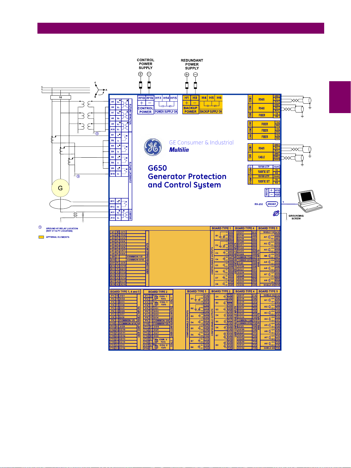
2 PRODUCT DESCRIPTION 2.5 EXTERNAL CONNECTIONS
2.5EXTERNAL CONNECTIONS
2
Figure 2–3: G650 WIRING DIAGRAM (189C4216H17R1)
GEK-113285A G650 Generator Protection & Control System 2-33
Page 63
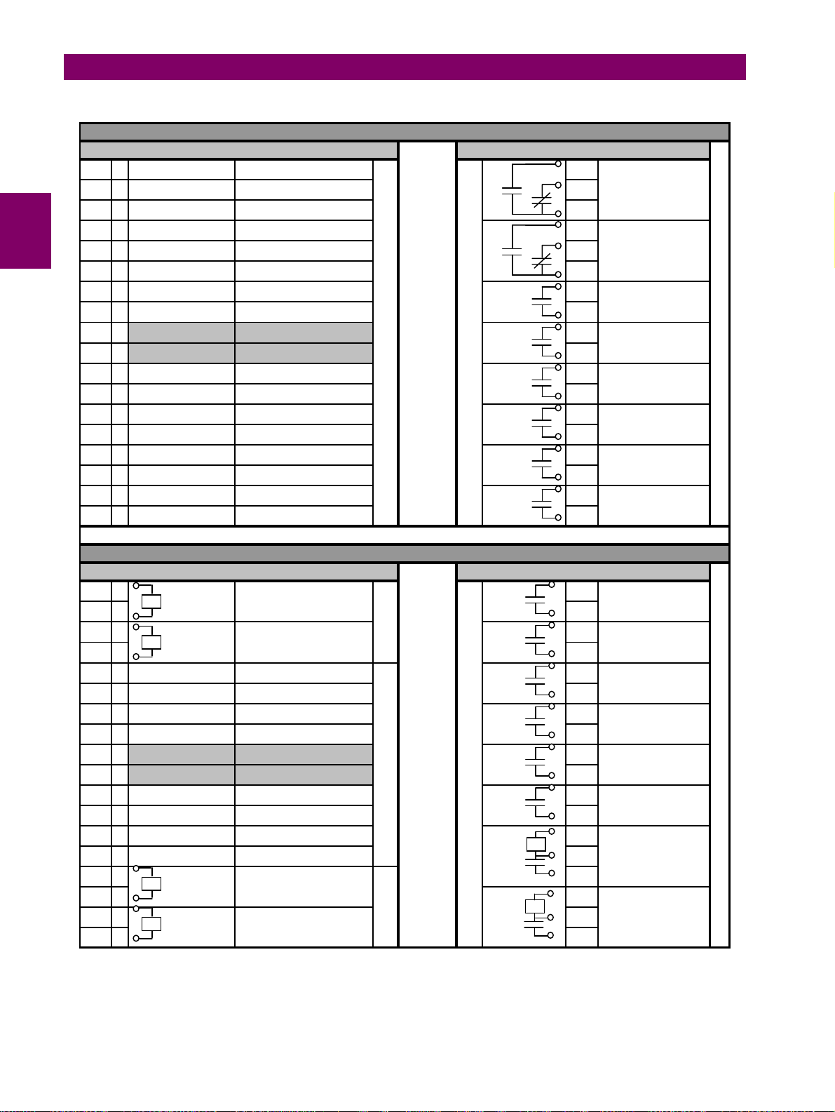
2.5 EXTERNAL CONNECTIONS 2 PRODUCT DESCRIPTION
USER
CONFIGURABLE
INPUTS
SLOT F CONFIGURATION (BOARD TYPE 1)
INPUTS F1 OUTPUTS F1
F1 + CC1
F2 + CC2
F3 + CC3
F4 + CC4
F5 + CC5
F6 + CC6
F7 + CC7
F8 + CC8
F9 - COMMON 1/8 COMMON 1/8
F10 - COMMON 9/16 COMMON 9/16
F11 + CC9 NOT USED
F12 + CC10 NOT USED
F13 + CC11 NOT USED
F14 + CC12 NOT USED
F15 + CC13 NOT USED
F16 + CC14 NOT USED
F17 + CC15 NOT USED
F18 + CC16 NOT USED
52b F19
50P BLOCK F20
O1 FREQ PICKUP
51P BLOCK F21
50-2 BLOCK F22
50G BLOCK F23
O2 27/59 PICKUP
51G BLOCK F24
51-2 BLOCK F25
67G BLOCK F26
USER CONFIGURABLE INPUTS
O3 50/67G PICKUP
O4 51/67G PICKUP
O5 50/67P PICKUP
O6 51/67P PICKUP
USER CONFIGURABLE OUTPUTS
O7
O8 TRIP
F27
F28
F29
F30
F31
F32
F33
F34
F35
F36
MANUAL
CLOSE
SLOT F CONFIGURATION (BOARD TYPE 2)
INPUTS F2 OUTPUTS F2
F1 + COIL 1
VVVV
SUPERVISION 52/a
O1 FREQ PICKUP
F2 - 52/a
F3 + COIL 1
SUPERVISION 52/b
COIL 1
O2 27/59 PICKUP
F4 - 52/b
F5 + CC1
F6 + CC2
F7 + CC3
F8 + CC4
F9 - COMMON 1/4 COMMON 1/4
52b F23
50P BLOCK F24
51P BLOCK F25
50-2 BLOCK F26
O3 50/67G PICKUP
O4 51/67G PICKUP
O5 50/67P PICKUP
F10 - COMMON 5/8 COMMON 5/8
F11 + CC5
F12 + CC6
F13 + CC7
F14 + CC8
F15 + COIL 2
50G BLOCK F29
51G BLOCK F30
51-2 BLOCK
67G BLOCK F32
O6 51/67P PICKUP
I SENS
O7
USER CONFIGURABLE OUTPUTS
SUPERVISION 52/a
F16 - 52/a I SENS
F17 + COIL 2
SUPERVISION 52/b
COIL 2
O8
F18 - 52/b
F19
F20
F21
F22
F27
F28
F31
I
MANUAL
CLOSE
F33
F34
I
F35
TRIP
F36
2-34 G650 Generator Protection & Control System GEK-113285A
Page 64
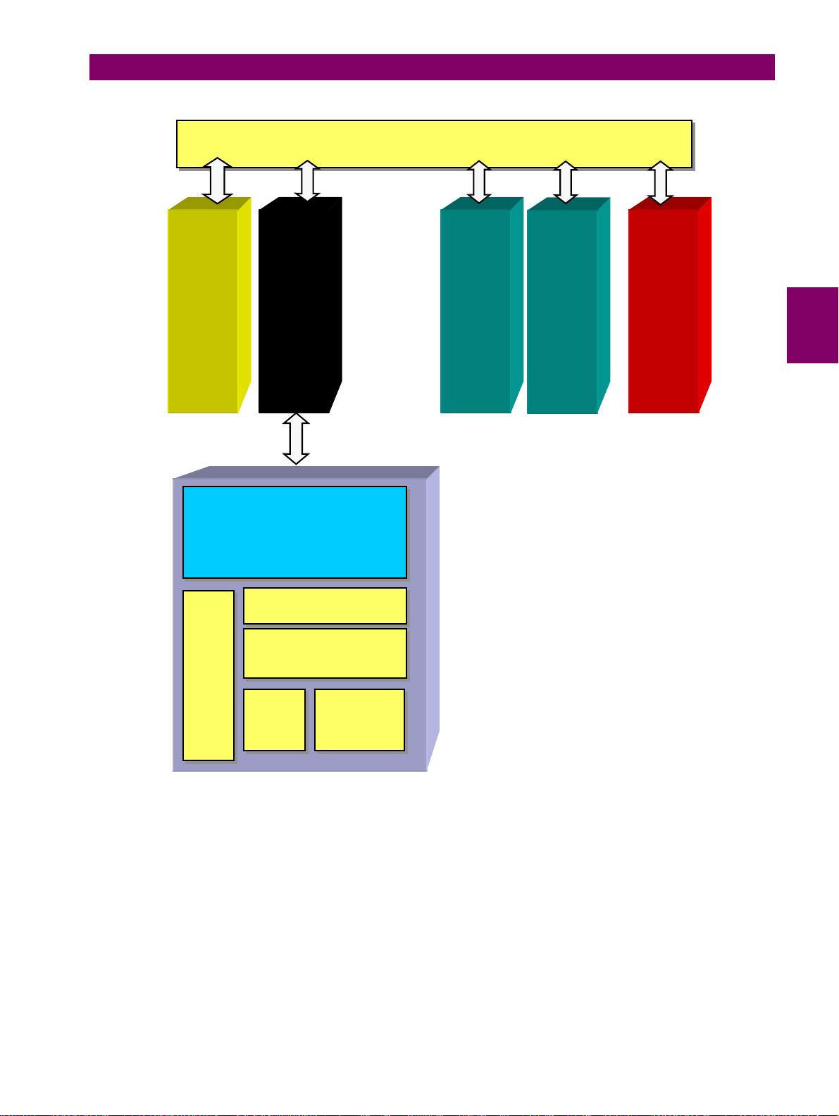
3 HARDWARE 3.1 MODULE DESCRIPTION
e
3 HARDWARE 3.1MODULE DESCRIPTION
AAnnaalloog
s
iinnppuutts
s
VVTTs
d
aannd
s
CCTTs
HHiigghhSSppeeeeddsseerriiaallCCAANNBBuus
g
CPU
Module
SCREEN
Digital
I/O
Optional
Digital
I/O
s
Power
Supply
3
KKeeyyppaad
s
s
D
D
E
E
L
L
G650 units incorporate the following modules:
• Power supply, which can be simple or redundant, depending on the selected model
• Front module with alphanumerical (4 x 20) or optional graphical (16 x 40 characters) display. It includes the bus
on its rear, which communicates with the rest of modules via a high speed CAN bus.
• Transformers module with 5 current transformers and 4 voltage transformers
• CPU including a powerful DSP for measure processing as well as synchronous and asynchronous communication
accessories.
• Input/Output module included in basic unit
• Optionally, a second I/O module can be added.
SShhuuttttlleekkeey
S
RRS
2
22332
d
y
LLooccaall/
RReemmoot
/
t
e
Figure 3–1: BLOCK DIAGRAM
GEK-113285A G650 Generator Protection & Control System 3-1
Page 65
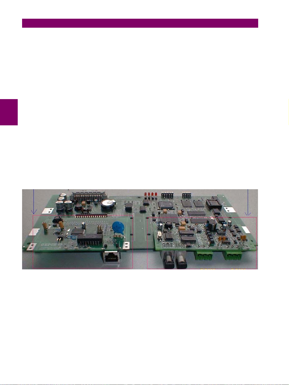
3.2 POWER SUPPLY 3 HARDWARE
3.2POWER SUPPLY
G650 can incorporate a simple or redundant power supply.
The power supply module is fixed to the base plate using 4 screws, and the main and backup modules are identical.
These modules work in parallel continuously, distributing the 50% of the load for each of them, thus ensuring greater
reliability, and an instantaneous load transfer from the failed power supply to the other one, without loss of time or module
reset.
A relay connected to the low voltage side of the power supply monitors this voltage. The three contact terminals, normally
open, common, and normally closed, are available at the external connector terminals. This relay monitors only the power
supply integrity and it is not controlled by the main microprocessor. This way, if we want a relay to monitor whether the unit
is ready to protect (READY), we should program one of the auxiliary relays in the unit.
This is a “fly-back” type power supply, providing high efficiency, stability and reliability thanks to the maturity of this
technology. There are two available ranges, Hi and Low, in order to optimize efficiency and general performance, including
the capability to tolerate auxiliary voltage interruptions (dips).
Oversized components highly resistant to temperature are used. For example, all capacitors are specified to stand up to
105ºC, transformer components are specially designed to stand up to 180ºC, the used MOSFET transistor is of very low
resistance, supports high voltage and is refrigerated by an oversized heat sink. This allows to support temperatures over
the 60ºC shown in the Technical Characteristics section, and prolonged overloads such as the ones occurring at batteries
in deep charge mode (much higher than +15% voltage shown in the Technical Characteristics section).
High capacitance capacitors are also used, providing high tolerance to prolonged dips, 100ms, even in the most
unfavorable consumption conditions. This allows the relay to continue with normal operation without undesired resets,
which would cause a long time of protection unavailability.
Figure 3–2: shows the location of communications modules over the CPU. These modules have been designed in
accordance with the “plug and play” philosophy, so that units can be easily updated after their purchase, allowing for a
simple and economical migration of the application.
Figure 3–2: COMMUNICATIONS MODULE
3-2 G650 Generator Protection & Control System GEK-113285A
Page 66
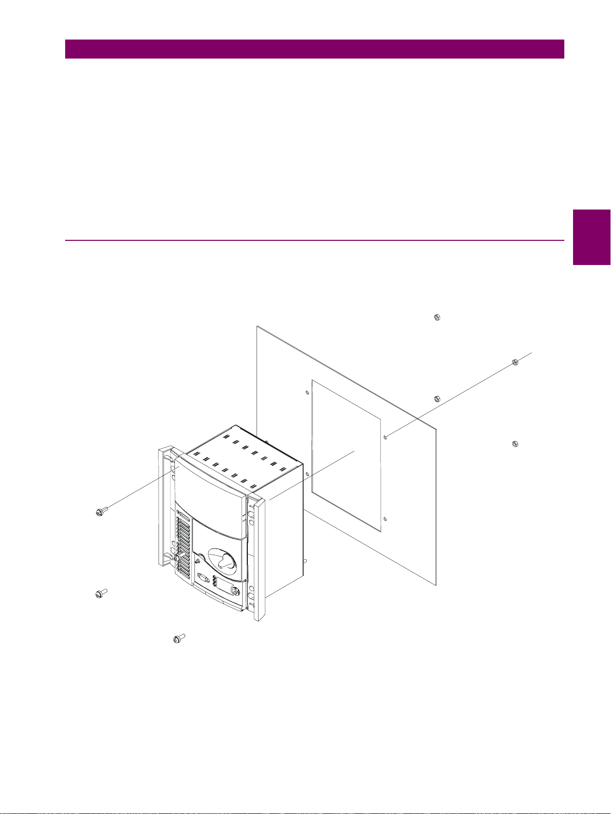
3 HARDWARE 3.3 MECHANICAL DESCRIPTION
3.3MECHANICAL DESCRIPTION
The model number and electrical characteristics of the unit are indicated on the label located on the right side of the relay
case.
The metallic case of the unit is highly resistant to corrosion. It is made of stainless steel (AISI 304), coated with an epoxy
layer, and the rest of the metallic pieces are covered with a high quality resistive coating that has successfully passed at
least 96 hours in the salt spray chamber (S/N ASTM B-117).
The front of the relay is made of a thermoplastic, flame retardant (V0), highly resistive material, which guarantees the unit’s
immunity to all kinds of EMI/RFI/ESD interferences. As well, an IP51 (IEC 529) protection degree against dust and water
through the front and with the relay mounted in the panel.
In order to guarantee safety and preventing access to the unit by unauthorized personnel, the front part of the relay has a
sealable cover to protect the RS 232 front port and the operation mode key.
3.3.1 MOUNTING
The unit is designed for semi-flush mounting . The relay is secured to the panel with the 4 M6 screws provided with the unit.
The user has access to the front keypad, display and communication port. The wiring is at the rear of the unit. The drilling
dimensions are shown on Figure 3–4:
3
Figure 3–3: PANEL MOUNTING
The relay width allows the mounting of two units on a standard 19’’ panel, 8 units high.
GEK-113285A G650 Generator Protection & Control System 3-3
Page 67
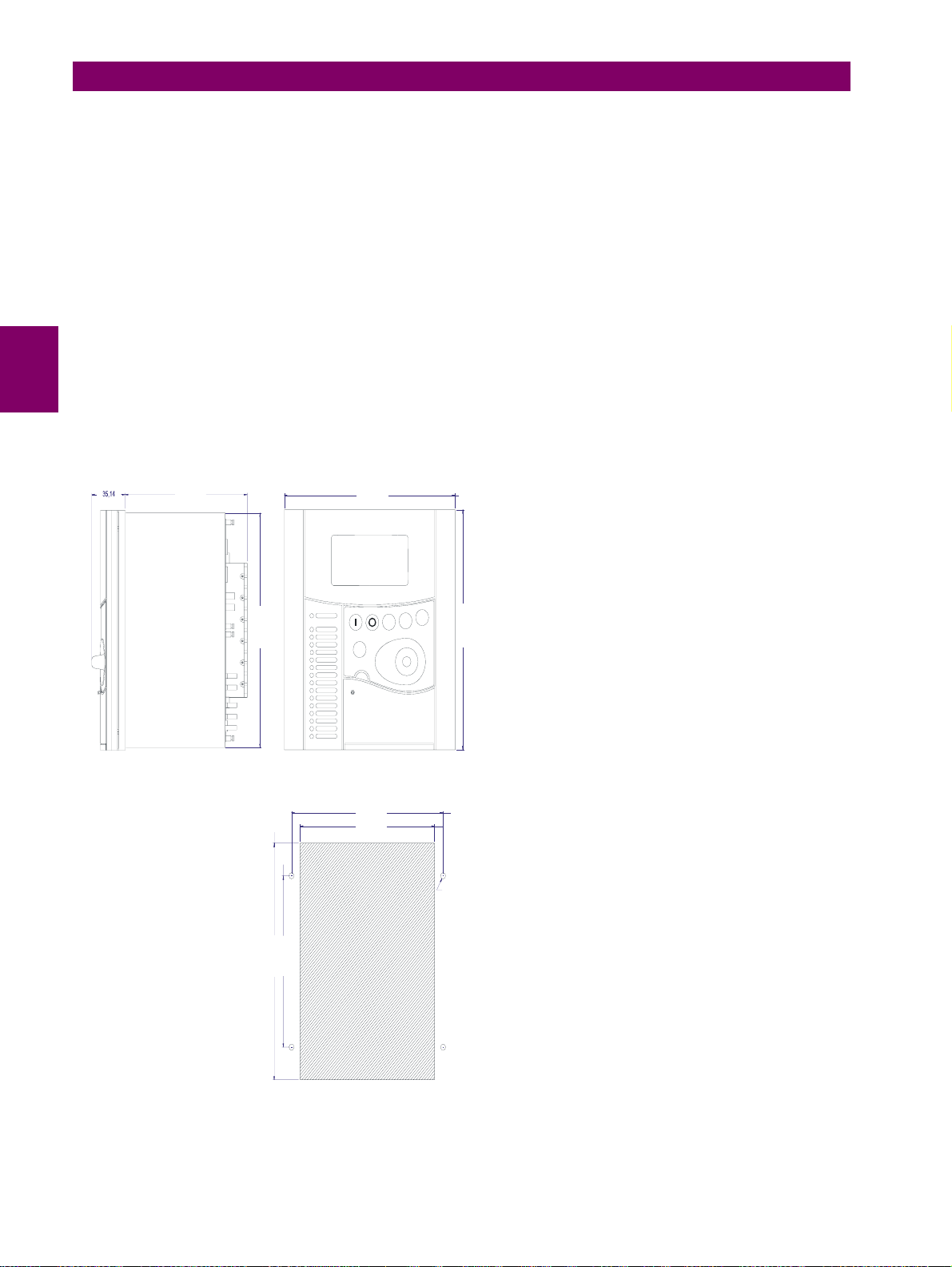
3.3 MECHANICAL DESCRIPTION 3 HARDWARE
(1,38)
169 ( 6,65 )
260,7 ( 10,26 )
( 9,30 )
237
F1
F2
*
ESC
266,7 ( 10,50 )
N
GE Multilin 650
SIDE VIEW
FRONT VIEW
210 ( 8,27 )
186 ( 7,32 )
4x O7 ( ,27 )
190,5 ( 7,5 )
263 ( 10,36 )
NOTE: All dimensions are shown in mm ( inches ).
PANEL MOUNTING CUTOUT
Figure 3–4: DRILLING DIMENSIONS DIAGRAM
3-4 G650 Generator Protection & Control System GEK-113285A
Page 68
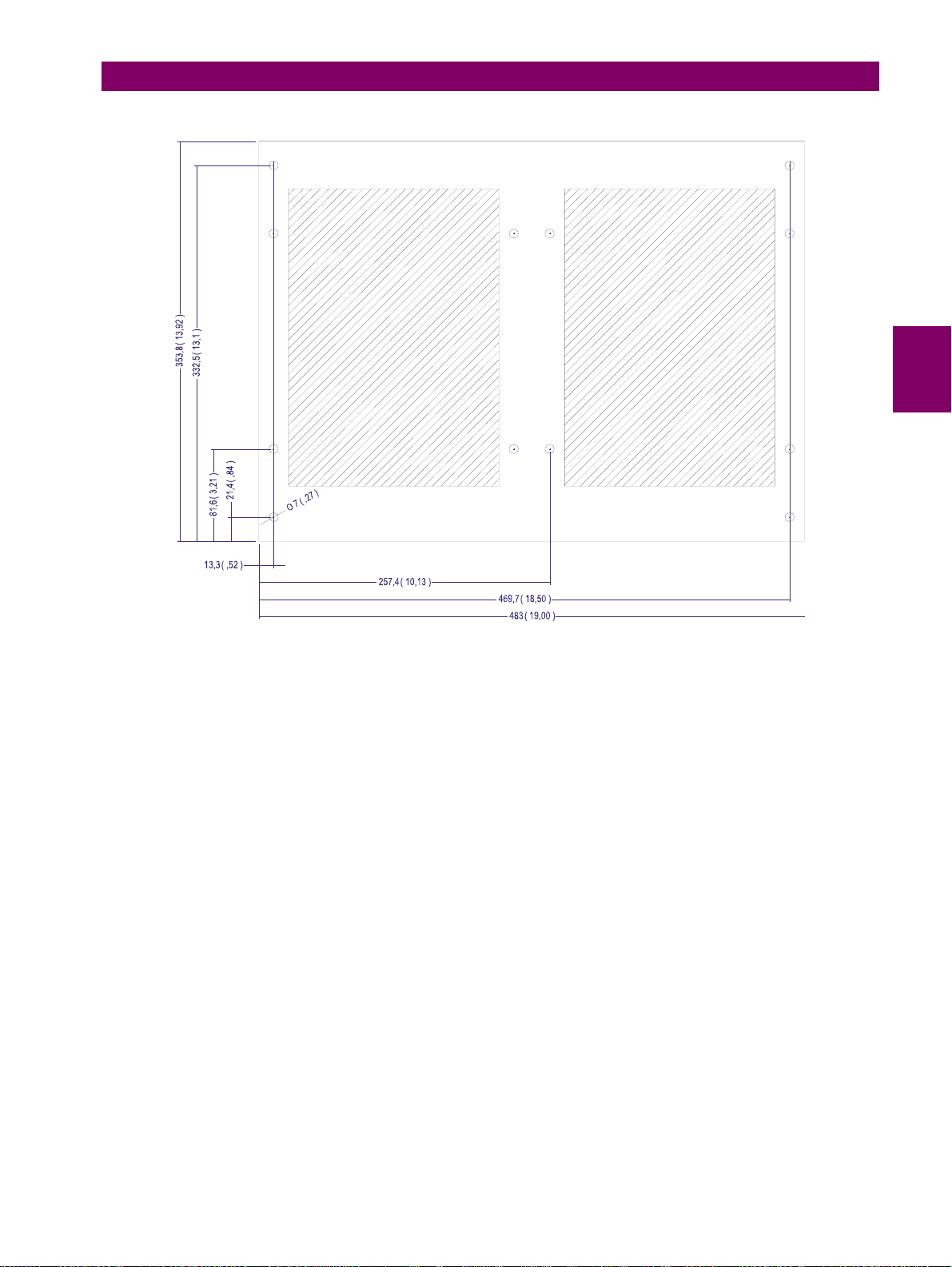
3 HARDWARE 3.3 MECHANICAL DESCRIPTION
3
Figure 3–5: DIMENSIONS OF THE 19” RACKS 8U HIGH FOR TWO RELAYS
GEK-113285A G650 Generator Protection & Control System 3-5
Page 69
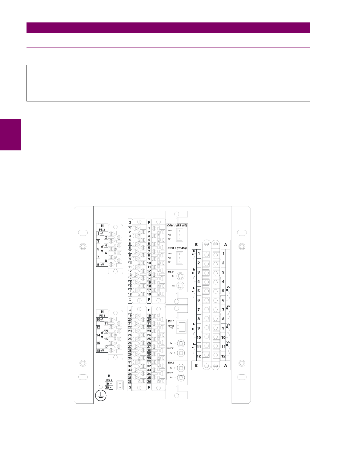
3.3 MECHANICAL DESCRIPTION 3 HARDWARE
3.3.2 REAR DESCRIPTION
WARNING
Module withdrawal and insertion may only be performed when control power has been removed from the unit.
Proper electrostatic discharge protection (i.e. a static wrap) must be used when coming in contact with
products while the relay is energized.
The relay is wired through the terminal blocks located at the rear of the unit.
The magnetic module, which receives the CT secondary currents and the metering voltages, incorporates a very robust
terminal board (columns A and B). Current inputs provide automatic shorting of external CT circuits. The maximum
recommended cable section for this terminal board, with the appropriate terminal, is 6 mm
2
(AWG 10).
The rest of the terminal blocks, F and G for I/O and H for power supply, incorporate high quality connectors with the
capacity to withstand a rated current of 15 A at 300 V. These terminal blocks admit a cable section of up to 2.54 mm2 (AWG
12).
The communication boards have a different type of connector depending on the selected media: RS485, glass or plastic
fiber optic.
Figure 3–6: CONNECTORS LOCATION
3-6 G650 Generator Protection & Control System GEK-113285A
Page 70
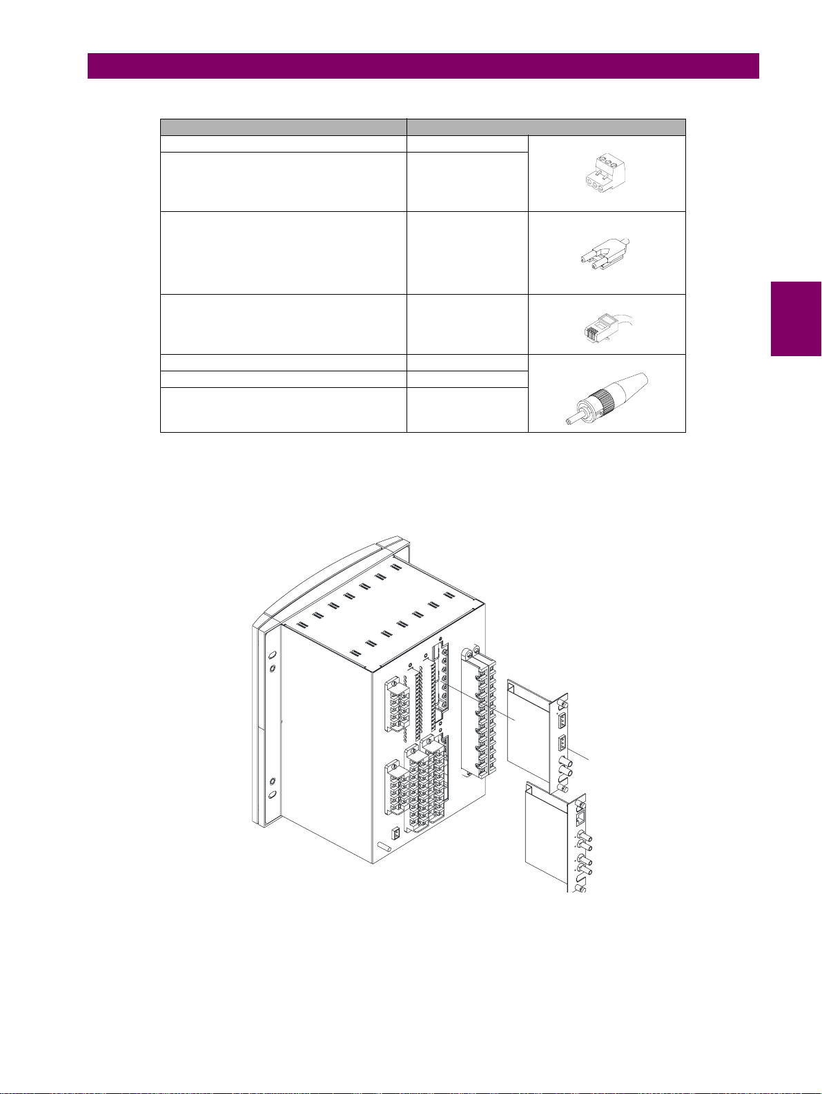
3 HARDWARE 3.3 MECHANICAL DESCRIPTION
TYPE OF COMMUNICATION CONNECTOR
RS485 / CAN cable Plug-in, 3 poles.
IRIG B Plug-in, 2 poles.
Plastic fiber optic Versatile Link
Ethernet 10/100 UTP (10/100BaseTX) RJ45, Class 5.
Glass fiber optic (100BaseFX) ST
Ethernet 100 FX (100BaseFX) ST
CAN Fiber ST
Figure 3–7: COMMUNICATIONS MEDIA SELECTOR GUIDE
3
Communication boards are installed at the rear part of the unit, the upper port being reserved for the asynchronous
communications board and CAN, and the lower port for the ETHERNET board in any of its configurations.
Figure 3–8: DETAIL OF INSERTION/EXTRACTION OF COMMUNICATION MODULES
The transformers module with the VTs and CTs is already connected to a female connector screwed to the case
that incorporates shorting bars in the current inputs, so that it can be extracted without the need to short-circuit
the currents externally . It is very import ant, for safety reasons not to change or swi f t the terminals for CTs and VTs.
GEK-113285A G650 Generator Protection & Control System 3-7
Page 71
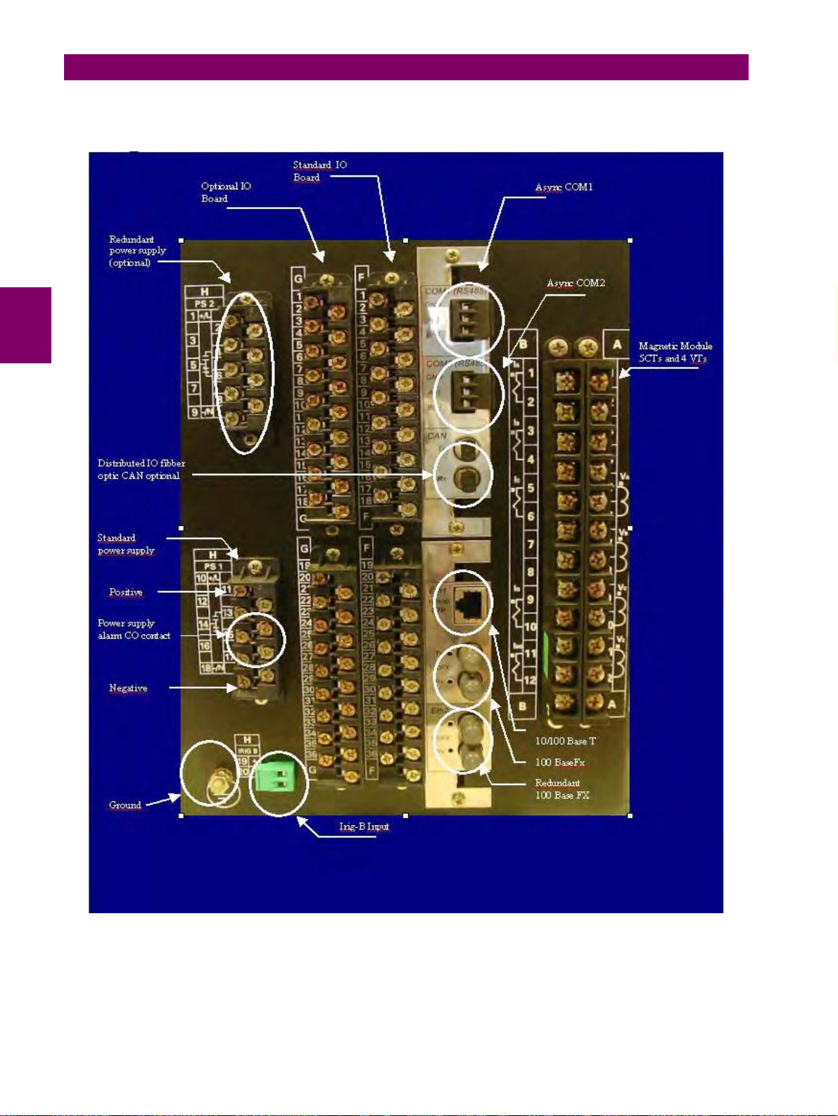
3.3 MECHANICAL DESCRIPTION 3 HARDWARE
A grounded antistatic wristband must be used when manipulating the module in order to avoid electrostatic discharges that
may cause damage to the electronic components.
Figure 3–9: REAR TERMINALS LOCATION
3-8 G650 Generator Protection & Control System GEK-113285A
Page 72

3 HARDWARE 3.4 WIRING
3.4WIRING 3.4.1 EXTERNAL CONNECTIONS
G650 units can hold different options for F module:
Option 1: Board with 16 digital inputs and 8 outputs.
Option 2: Board with 8 digital inputs, 4 circuit supervision inputs, 6 conventional outputs, and two current sensing
outputs
Option 4: Board with 32 digital inputs.
Option 5: Board with 16 digital inputs and 8 analog inputs.
For slot G there are four different options:
Option 0: No board
Option 1: Board with 16 digital inputs and 8 outputs.
Option 4: Board with 32 digital inputs.
Option 5: Board with 16 digital inputs and 8 analog inputs.
The number selected for slot G must be equal or higher than the number selected for option F for models including boards
4 and 5.
3.4.2 DIGITAL INPUTS WITH TRIP CIRCUIT SUPERVISION
3
The Option 2 I/O board includes two groups of 4 inputs with one common, in terminals F9 to F10. It also includes 6 auxiliary
outputs, in terminals F19 to F30 with normally open contacts and two current sensing (latching) outputs (F31-F33 and F34F36).
Besides, there are 2 groups of inputs for trip circuit supervision. The first group includes two isolated digital inputs, terminals
F1-F2 and F3-F4. The second group, symmetrical and identical to the first, is formed by isolated voltage inputs F15-F16
and F17-F18.
Using voltage detectors and current sensing, it is possible to implement several trip or close circuit supervision schemes, as
well as protection of the unit output contact.
In order to implement these schemes, it is not necessary to perform any setting in the unit. Internal functions are
always operative. The detailed description of trip circuit supervision is included in chapter 5 in this manual.
GEK-113285A G650 Generator Protection & Control System 3-9
Page 73
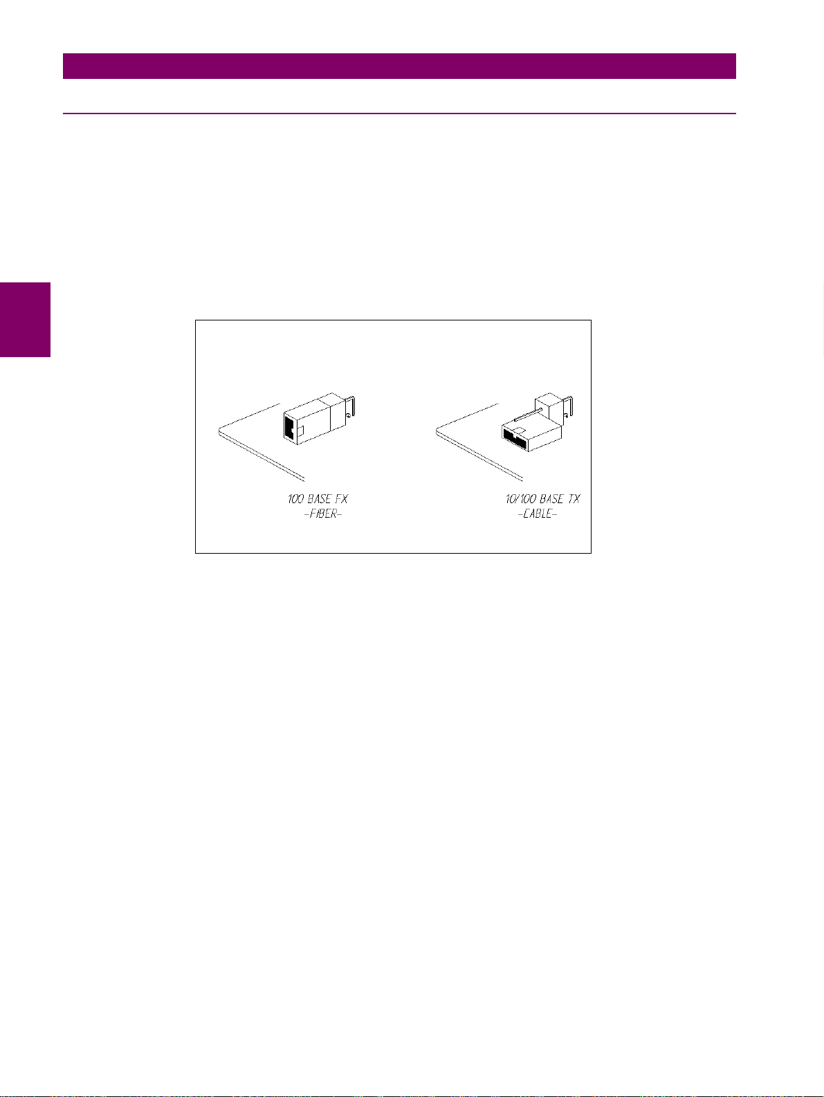
3.4 WIRING 3 HARDWARE
3.4.3 CABLE/FIBER ETHERNET BOARD
The Ethernet board is the communication board 2 (COM3) shown in Figure 3–2:. It is located in the bottom at the rear part
of the relay.
In Models C and D, the 10/100BaseTX port is selected by an internal switch. To select between fiber and cable it is
necessary to extract the board, switch the jumper to the selected position, as indicated on Figure 3–10: FIBER/CABLE
SELECTION and insert the board again. As with any other relay manipulation, the relay power supply must be removed
and the operation must be performed only by skilled personnel.
The default port selected by switch is 10/100 TX in factory configuration. The switch selects between cable (10/100 TX) and
the first fiber port (100 FX). In Ethernet board type D (double fiber port) the backup channel is always fiber.
Figure 3–10: FIBER/CABLE SELECTION
3-10 G650 Generator Protection & Control System GEK-113285A
Page 74
3 HARDWARE 3.5 TRANSCEIVER OPTICAL POWER BUDGET VERSUS LINK LENGTH
3.5TRANSCEIVER OPTICAL POWER BUDGET VERSUS LINK LENGTH
Optical Power Budget (OPB) is the available optical power for a fiber optic link to accommodate fiber cable losses plus
losses due to in-line connectors, splices, optical switches, and to provide margin for link aging and unplanned losses due to
cable plant reconfiguration and repair.
OPB (DB) FIBER OPTIC CABLE
62.5/125 μm 50/125 μm
11. 4 8 0
10.9 7.4 0.3
10.5 7.1 0.5
9.6 6.2 1.0
8.5 5.3 1.5
7.3 4.3 2.0
63.32.5
LENGTH (KM)
3
GEK-113285A G650 Generator Protection & Control System 3-11
Page 75

3.5 TRANSCEIVER OPTICAL POWER BUDGET VERSUS LINK LENGTH 3 HARDWARE
3-12 G650 Generator Protection & Control System GEK-113285A
Page 76

4 HUMAN INTERFACES. SETTINGS & ACTUAL VALUES 4.1 ENERVISTA 650 SETUP SOFTWARE INTERFACE
4 HUMAN INTERFACES. SETTINGS & ACTUAL VALUES 4.1ENERVISTA 650 SETUP SOFTWARE INTERFACE
4.1.1 INTRODUCTION
The EnerVista 650 Setup software provides a graphical user interface (GUI) as one of two human interfaces to a 650
device. The alternate human interface is implemented via the device’s faceplate keypad and display (see Human Machine
Interface section in this chapter).
The EnerVista 650 Setup software provides a single facility to configure, monitor, maintain, and trouble-shoot the operation
of relay functions, connected over local or wide area communication networks. It can be used while disconnected (i.e.
offline) or connected (i.e. on-line) to a 650 device. In off-line mode, settings files can be created for eventual downloading to
the device. In on-line mode, you can communicate with the device in real-time.
The EnerVista 650 Setup software, provided with every G650 relay, can be run from any computer supporting Microsoft
Windows
interface features. The EnerVista 650 Setup Help File provides details for getting started and using the EnerVista 650
Setup software interface.
This software package uses ModBus protocol, and it is designed to communicate with a single relay at a time. GE offers
different communication software packages, such as GE-POWER, which can be used to communicate simultaneously with
several relays.
EnerVista 650 Setup software provides an easy way to configure, monitor and manage all G650 features.
® 95, 98, NT, 2000, ME, and XP. This chapter provides a summary of the basic EnerVista 650 Setup software
4.1.2 ENERVISTA 650 SETUP SOFTWARE OVERVIEW
4
4.1.2.1 ENGAGING A DEVICE
The EnerVista 650 Setup software may be used in on-line mode (relay connected) to directly communicate with a 650
device.
4.1.2.2 USING SETTINGS FILES
The EnerVista 650 Setup software interface supports three ways of handling changes to relay settings:
1. In off-line mode (relay disconnected) to create or edit relay settings files for later download to communicating relays.
2. While connected to a communicating relay to directly modify any relay settings via relay data view windows, and then
save the settings to the relay.
3. You can create/edit settings files and then write them to the relay while the interface is connected to the relay.
Settings files are organized on the basis of file names assigned by the user. A settings file contains data pertaining to the
following types of relay settings:
•Product Setup
•System Setup
•Protection Elements
•Control Elements
•Inputs/Outputs
•Relay Configuration
•Logic Configuration
4.1.2.3 VIEWING ACTUAL VALUES
You can view real-time relay data such as input/output status and measured parameters.
GEK-113285A G650 Generator Protection & Control System 4-1
Page 77

4.1 ENERVISTA 650 SETUP SOFTWARE INTERFACE 4 HUMAN INTERFACES. SETTINGS & ACTUAL VALUES
4.1.2.4 VIEWING TRIGGERED EVENTS
While the interface is in either on-line or off-line mode, you can view and analyze data generated by triggered specified
parameters, via one of the following:
• Event Recorder facility: The event recorder captures contextual data associated with the last 479 events, listed in
chronological order from most recent to oldest.
• Oscillography facility: The oscillography waveform traces and digital states are used to provide a visual display of
power system and relay operation data captured during specific triggered events.
4.1.2.5 FIRMWARE UPGRADES
The firmware of a G650 device can be upgraded, locally or remotely, via the EnerVista 650 Setup software. The
corresponding instructions are provided by the EnerVista 650 Setup Help file under the topic “Upgrading Firmware”.
Modbus addresses assigned to firmware modules, features, settings, and corresponding data items (i.e. default values,
minimum/maximum values, data type, and item size) may change slightly from version to version of firmware.
The addresses are rearranged when new features are added or existing features are enhanced or modified.
4.1.2.6 ONE LINE DIAGRAMS
You can configure an one line diagram (bay mimic) to be used in relays with graphical display.
4-2 G650 Generator Protection & Control System GEK-113285A
Page 78
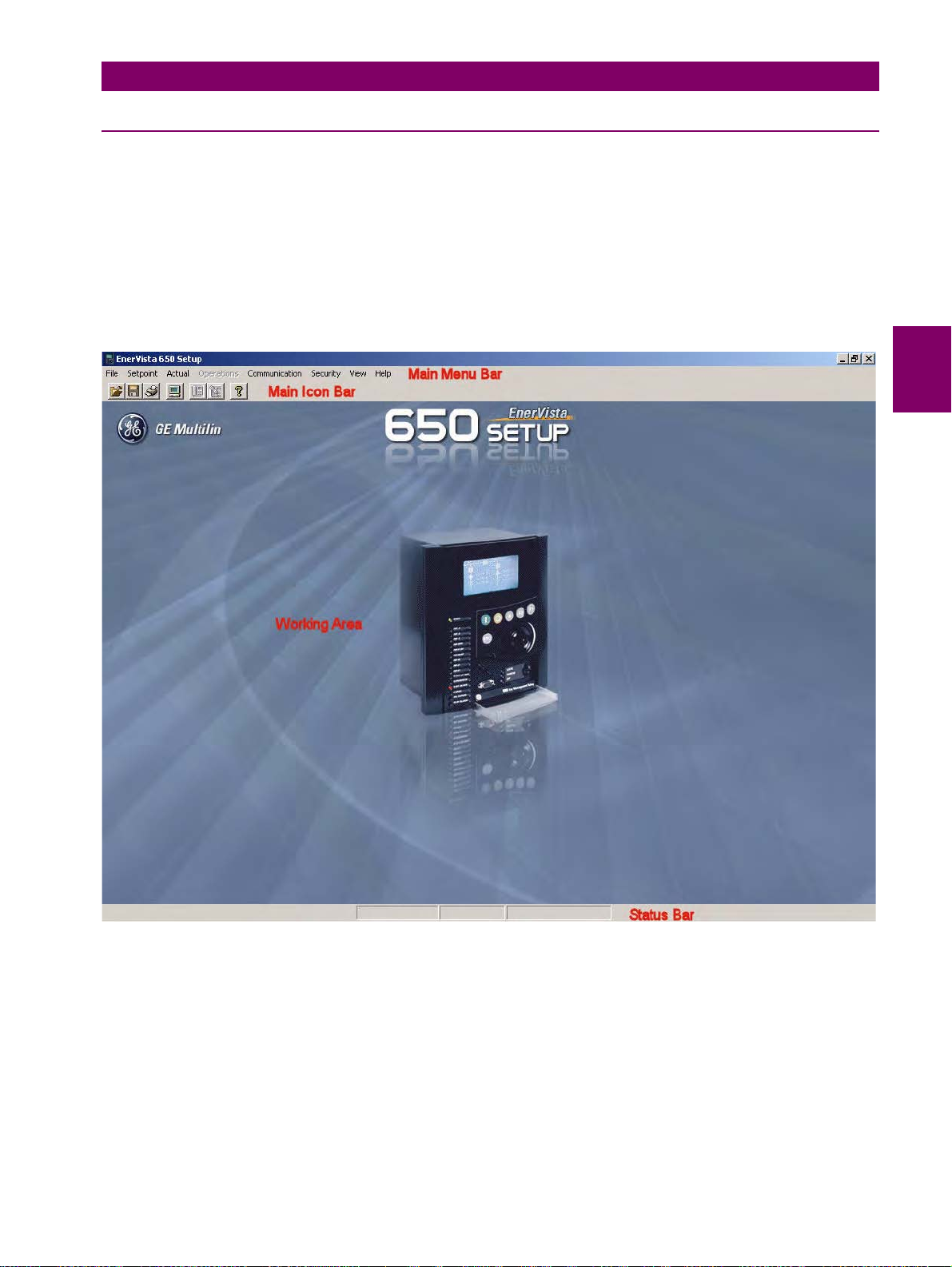
4 HUMAN INTERFACES. SETTINGS & ACTUAL VALUES 4.1 ENERVISTA 650 SETUP SOFTWARE INTERFACE
4.1.3 MAIN SCREEN
The EnerVista 650 Setup software main window supports the following primary display components:
• Title bar
• Main menu bar
• Main icon bar
• Working area
• Status bar
Title
4
Working Area
Figure 4–1: ENERVISTA 650 SETUP MAIN SCREEN
GEK-113285A G650 Generator Protection & Control System 4-3
Page 79
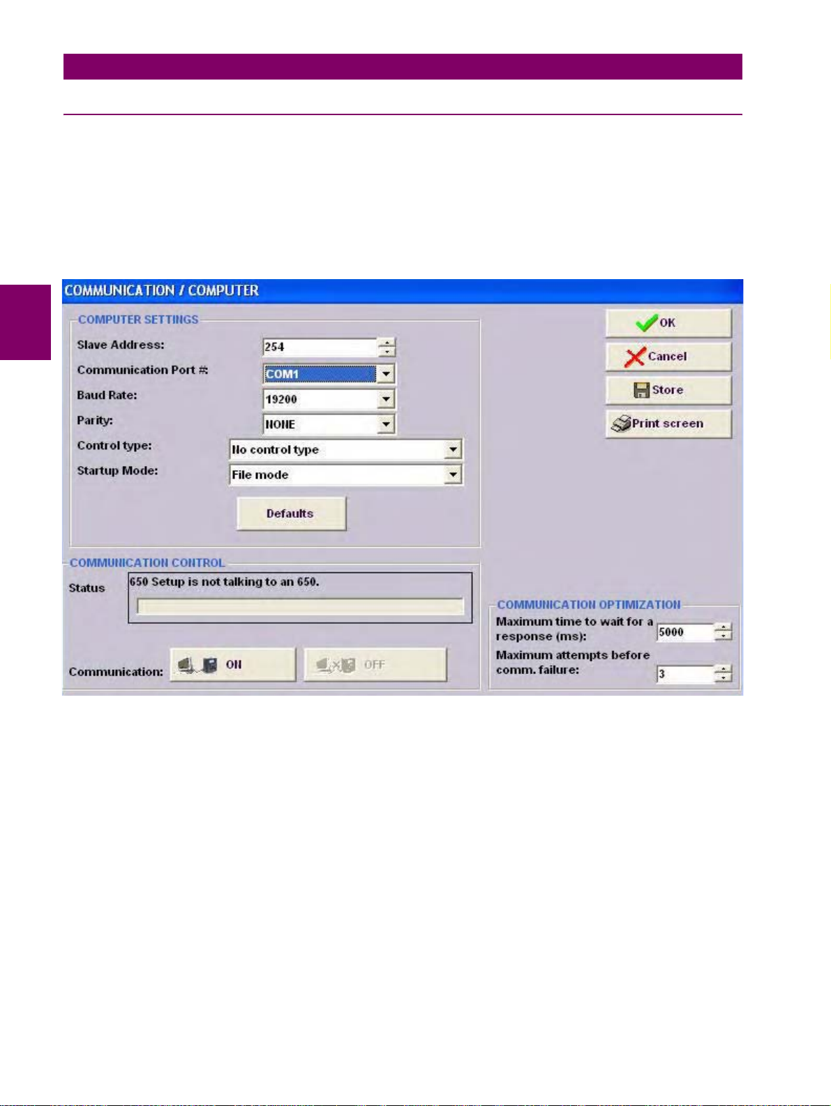
4.1 ENERVISTA 650 SETUP SOFTWARE INTERFACE 4 HUMAN INTERFACES. SETTINGS & ACTUAL VALUES
4.1.4 COMMUNICATION MENU
To start communicating with the relay go to “Communication>Computer>Computer settings” section in the main
EnerVista 650 Setup menu.
Safety instructions must be followed before connecting the computer to the relay. Safety instructions are detailed in section
1.1.3. Connect the relay ground terminal and the communicating computer to a good grounding. Otherwise, communication
may not be viable, or even, in worst cases, the relay and/or the computer could result damaged by overvoltages.
For on-line working, previously ensure that all relay communication parameters, such as baudrate, slave ModBus address,
etc., match the computer settings.
Figure 4–2: COMMUNICATION PARAMETERS MENU
The “Communication > computer” screen is divided in several subsections:
• Computer settings: Main communication parameters for serial communication and control type selection.
• ModBus/TCP Setup (if ModBus /TCP is selected as control type): Communication parameters for ModBus TCP
communication.
• Communication control: Device communication status (communicating or not communicating).
• Communication optimization: allows optimizing the communication time outs and failure establishing.
4-4 G650 Generator Protection & Control System GEK-113285A
Page 80

4 HUMAN INTERFACES. SETTINGS & ACTUAL VALUES 4.1 ENERVISTA 650 SETUP SOFTWARE INTERFACE
4.1.4.1 COMPUTER SETTINGS:
Shows the communication parameters necessary in order to establish communication with the unit. Such as slave address,
communication port, baud rate, parity, control type and startup mode.
Baud rate, parity, data bits, stop bits and ModBus slave address for com2 (RS232 front port and second serial port in the
rear communication board) are displayed in the default text logotype main screen.
ModBus Slave Address: ModBus addresses used for serial and Ethernet communication.
Communication ports: port used in the computer for serial communication.
Baud Rate: Baud rate for serial communication (from 1200 up to 115200 bauds in EnerVista 650 Setup, from 300 to
115200 in relay).
Parity: parity for serial communication. None, odd or even can be selected.
Control Type: The available control modes are:
• No Control Type, this option selects the serial communication mode, for use with serial communication ports (front
port, RS485, or plastic or glass fiber optic).
• MODBUS/TCP, this option selects ModBus TCP/IP communication mode, for communication through the Ethernet
port. In this case, the top right window will show the typical parameters to be programmed; IP address, port address
and unit identifier in the MODBUS TCP SETUP section.
• MODEM, this option displays the parameter to set in case of using a modem for the communication, such as Phone
number, Time out (sec.), init. command, type of dialing (tones or pulses).
4.1.4.2 COMMUNICATION CONTROL:
Located at the bottom of the screen, it shows the status of the communication with the relay. With relay not communicating,
a message “650 Setup is not talking to an 650” will be shown and ON button will be enable. Pressing this button, 650 Setup
start communicating with the relay.
With relay communicating a message “650 Setup is now talking to an 650” will be shown and OFF will be enable. Pressing
this button, communications between relay and PC will be closed.
4
4.1.4.3 COMMUNICATION OPTIMIZATION:
The parameters shown on the bottom right window (Communication optimization) can improve communication, although it
is recommended to leave the default values indicated by the EnerVista 650 Setup. These parameters are the maximum
time to wait for a response in the relay (in ms) and the maximum attempts to perform before assuming communications
failure.
GEK-113285A G650 Generator Protection & Control System 4-5
Page 81
4.1 ENERVISTA 650 SETUP SOFTWARE INTERFACE 4 HUMAN INTERFACES. SETTINGS & ACTUAL VALUES
(
)
y
p(
)
(
)
gn(
pp
4.1.5 FILE MANAGEMENT
File management with EnerVista 650 Setup software:
4.1.5.1 OFF LINE MODE
Run EnerVista 650 Setup
Open a *.650 file
“File>Open” menu
Modify protection Settings
and rela
configuration
Is it necessary to
program
additional logic?
NO NO
YES
Launch the Logic Configuration tool in EnerVista
650 Setu
Create new or modify the existing logic:
Compile and save logic file (*.pep) and drawing
desi
Exit PLC Graphic Editor and save the *.650 file
“Setpoint>Logic Configuration”
“File>Open Project”
*.aut) in Logic Configuration tool
from the main a
lication menu
Is the relay
completely
configured?
YES
Save *.650 settings & configuration file
Store in the computer the Logic configuration files (*.pep, *.aut, *.lib) as
4-6 G650 Generator Protection & Control System GEK-113285A
well as the *.650 for further logic changes.
Figure 4–3: OFF-LINE MODE FILE MANAGEMENT
Page 82
4 HUMAN INTERFACES. SETTINGS & ACTUAL VALUES 4.1 ENERVISTA 650 SETUP SOFTWARE INTERFACE
T able 4–1: TYPES OF FILES GENERATED BY ENERVISTA 650 SETUP SOFTWARE OPERATION MODE OFF-LINE:
SETTINGS & CONFIGURATION FILE *.650
Description Protection Settings and Configuration Section
Created by EnerVista 650 Setup
Relay configuration file containing all protection
Contents
How to save
How to open
How to
transfer to
relay
elements Settings, input/output and LEDs configuration,
graphic display configuration, etc.
Equations corresponding to the logic created and
compiled in the PLC Editor
EnerVista 650 Setup:
“File>Save *”
EnerVista 650 Setup:
“File>Open *”
Connect with the relay
(“Communications>Computer”)
Open the created file (“File>Open *”)
Send to relay from the menu: “File>Send info to relay”
Note that texts used in the configuration of inputs,
outputs, etc. are not sent to the relay. The only texts
sent to relay are operations, events, and LEDs.
LOGIC CONFIGURATION FILES (*.PEP, *AUT, *.LIB)
*.PEP *.AUT *.LIB
Graphical edition
Header for Logic
project
Logic configuration
graphic editor (PLC
Editor)
PLC project file
containing the
necessary
information relative
to the relay model,
logic libraries
included in the
project (*.lib),
graphic file name
(*.aut), etc.
PLC Editor:
“File>Save
Project”
PLC Editor:
“File>Open
Project”
Connect with the relay (“Communications>Computer”)
Launch Logic equations Editor (“Setpoint>Logic
Configuration”)
Open the created PLC project (“File>Open Project”)
Compile the project (“Run>Compile”)
Now the logic (virtual outputs) can be sent directly to relay
(“Run>Send Equations to Relay”). Texts of virtual outputs are
not stored in the relay, only in the logic configuration files to be
edited.
container. Logic
equations (Virtual
Outputs) in FDB
format.
Logic configuration
graphic editor (PLC
Editor)
PLC Project file
containing all the
drawings used by
the logic, required by
650 relay based on
IEC 61131-3
standard. Functional
block diagram
(FDB).
PLC Editor:
“File>Save
Project”
PLC Editor:
“File>Open
Project”
User programmable
logic objects
Logic configuration
graphic editor (PLC
Editor)
Library file to be
included as an
object in a PLC
project. Logic
packages that can
be stored into
libraries and be
distributed in
different PLC
projects.
PLC Editor:
“File>Save
Library”
PLC Editor:
“File>Library>New
Library”
4
In case of using element libraries (either existing (“File Library>Open Library”) or created by the user (“File Libra r y> New
Library”), the program will create and manage the corresponding files (*.lib) in a folder named FDB (Functional Block
Diagram). These files are used for the PLC project compilation. It is necessary to store them with the other logic
configuration files that built the PLC project (*.pep, *.aut, *.lib).
Besides sending basic information to the relay (Settings + configuration) in *.650 format, it is recommended to store *.650,
*.pep, *.aut and *.lib files inside the relay (“Communication>Upload info files to relay”), to ensure that logic configuration
files will be available in the future for further logic modifications; either if these files are not used by the relay, they are
required for connecting to a relay and analyzing its configuration. The program manages the logic configuration files
globally, so that when the user selects to save file *.pep in the relay, the associated *.aut and *.lib files are also stored.
File storage inside the relay
(RECOMMENDED)
Retrieval of files stored in the relay
(RECOMMENDED)
“Communication > Upload info files to relay” through Ethernet
“Communication > Download info files from relay” through Ethernet
GEK-113285A G650 Generator Protection & Control System 4-7
Page 83
4.1 ENERVISTA 650 SETUP SOFTWARE INTERFACE 4 HUMAN INTERFACES. SETTINGS & ACTUAL VALUES
(
)
y
p(
)
(
)
y
r
4.1.5.2 ON LINE MODE
Run EnerVista 650 Setup
Connect to the relay
“Communication>Computer>ON”
NO
Modify and send to the
relay protection Settings
and rela
configuration
YES
Is it necessary to
program
additional logic?
Launch the Logic Configuration tool in EnerVista
650 Setu
“Setpoint>Logic Configuration”
Create new or modify the existing logic
“File>Open Project”
NO
and save logic file (*.pep) and drawing design
(*.aut) in Logic Configuration tool (“File>Save
Send logic to relay (“Run>Send Equations to
Is the relay
completely
configured?
Compile (“Run>Compile”)
Project”)
”) and Exit PLC Graphic Edito
Rela
YES
Save all settings & configuration (“File>Get info from relay”)
Store in the relay the Logic configuration files (*.pep, *.aut, *.lib) as well as the
*.650 for further logic changes. (“Communication>Upload info files to relay”)
Figure 4–4: ON LINE MODE FILE MANAGEMENT
4-8 G650 Generator Protection & Control System GEK-113285A
Page 84
4 HUMAN INTERFACES. SETTINGS & ACTUAL VALUES 4.1 ENERVISTA 650 SETUP SOFTWARE INTERFACE
Table 4–2: TYPES OF FILES CREATED BY ENERVISTA 650 SETUP– ONLINE OPERATION MODE
SETTINGS & CONFIGURATION FILE *.650
Description Protection Settings and Configuration Section
Created by EnerVista 650 Setup
Relay configuration file containing all protection
Contents
How to
transfer to
relay
elements, settings, input/output and LEDs configuration,
graphic display configuration, etc.
Equations corresponding to the logic created and
compiled in the PLC Editor
Connect with the relay (“Communications>Computer”) Connect with the relay (“Communications>Computer”)
Send settings and configuration from file
LOGIC CONFIGURATION FILES (*.PEP, *.AUT, *.LIB)
*.PEP *.AUT *.LIB
Graphical edition
Header for Logic
project
Logic configuration
graphic editor (PLC
Editor)
PLC project file
containing the
necessary
information relative
to the relay model,
logic libraries
included in the
project (*.lib),
graphic file name
(*.aut), etc.
Launch 650 Logic equations editor (“Setpoint>Logic
Configuration”)
Open the created PLC project (“File>Open Project”)
Compile the project (“Run>Compile”)
Now the logic (virtual outputs) can be sent directly to relay
(“Run>Send Equations to Relay”). Texts of virtual outputs are
not stored in the relay, only in the logic configuration files to be
edited.
container. Logic
equations (Virtual
Outputs) in FDB
format.
Logic configuration
graphic editor (PLC
Editor)
PLC Project file
containing all the
drawings used by
the logic, required
by 650 relay based
on IEC 61131-3
standard.
Functional block
diagram (FDB).
User programmable
logic objects
Logic configuration
graphic editor (PLC
Editor)
Library file to be
included as an object
in a PLC project.
Logic packages that
can be stored into
libraries and be
distributed in different
PLC projects.
4
Modify settings and configuration directly in the relay:
PLC Editor:
“File>Save Project” “File>Save Library”
How to save
How to store in the relay “Communication>Upload info files to relay” through Ethernet
How to retrieve from the relay
EnerVista 650 Setup:
“File>Get info from relay”. User definable texts
retrieved are operations, events, and LEDs.
The relay will not
provide this
information unless
the *.pep file is
stored in the relay
To store the logic configuration files in the relay use the
“Communication>Upload info files to relay” option
“Communication/Download info files from relay” through
Ethernet
The relay will not
provide this
information unless
the *.pep file is
stored in the relay.
The relay will not
provide this
information unless
the *.pep file is stored
in the relay.
REMINDER:
Logic programming support files (*.pep, *.aut, *.lib) CANNOT be retrieved directly from the relay.
It is necessary
* Either to have stored these files in the PC
* Or to have uploaded previously the files into the relay (“Communication>Upload info files to relay”)
GEK-113285A G650 Generator Protection & Control System 4-9
Page 85
4.1 ENERVISTA 650 SETUP SOFTWARE INTERFACE 4 HUMAN INTERFACES. SETTINGS & ACTUAL VALUES
4.1.6 ENERVISTA 650 SETUP MENU STRUCTURE
The EnerVista 650 Setup menus structure is shown in Table 4–3:.
Unless specified, options are available in both On-line and Off-line mode.
Options enabled only in On-line mode are marked as (*)
Options enabled only in Off-line mode are marked as (**)
The “View > Langua ge” submenu allows the user to change the default language for the EnerVista 650 Setup program and
it is only enabled when the relay is not communicating and no file has been opened.
Table 4–3: ENERVISTA 650 SETUP MENUS STRUCTURE
FILE SETPOINT ACTUAL
New (**) Product Setup Front Panel NA Computer Login user Traces
Open (**) System Setup Status NA Modem (*)
Save (**)
Save As
(**)
Close (**) Inputs/Outputs Records (*) NA
Config File
Converter
Properties
(**)
Get info
from relay
(*)
Send info
to relay (*)
Print Setup
(**)
Print
Preview
(**)
Print (**) NA
Print to file
(**)
Exit
Protection
Elements
Control
Elements
Relay
Configuration
Logic
Configuration
Clock (*) NA
Metering NA Troubleshooting (*)
Inputs/Outputs NA Calibration (*)
OPERATIONS
(*)
NA
NA
NA
NA
NA
COMMUNICATION SECURITY VIEW HELP
Instruction
Manual
Upgrade firmware
version (*)
Upgrade operating
system (*)
Upgrade 650 Web
Server
Upload info files to
relay
Download info files
from relay
Change
Password
User
Management
ModBus
Memory
Map
GE Multilin
on the web
About
EnerVista
650 Setup
4-10 G650 Generator Protection & Control System GEK-113285A
Page 86
4 HUMAN INTERFACES. SETTINGS & ACTUAL VALUES 4.1 ENERVISTA 650 SETUP SOFTWARE INTERFACE
4.1.7 FILE MENU OVERVIEW
Table 4–4: GENERAL OVERVIEW OF FILE MENU:
FILE
New (**)
Open (**) Open a settings and configuration file for off-line working.
Save (**) Save *.650 settings and configuration file
Save As (**) Save as *.650 settings and configuration file.
Close (**) Close the opened *.650 file in EnerVista 650 Setup.
Config File (*.650)
Converter
Properties (**) File properties for *.650.
Get info from relay (*)
Send info to relay (*) Send and write the *.650 settings and configuration to the relay.
Print Setup (**) To configure printer settings.
Print Preview (**) Preview of settings and configuration file printing format.
Print (**) Launch the *.650 file to be printed.
Print to file (*.xls) (**) *.650 printed to file in excel format.
Exit Quit the application closing all the open windows.
Create a new settings and configuration file, with the default relay
settings and no configuration
Tool to convert the *.650 files from one version to another
Retrieve the *.650 settings and relay configuration compiled equations
from the relay.
4
Options enabled only in On-line mode are marked as (*). Options enabled only in Off-line mode are marked as (**)
GEK-113285A G650 Generator Protection & Control System 4-11
Page 87
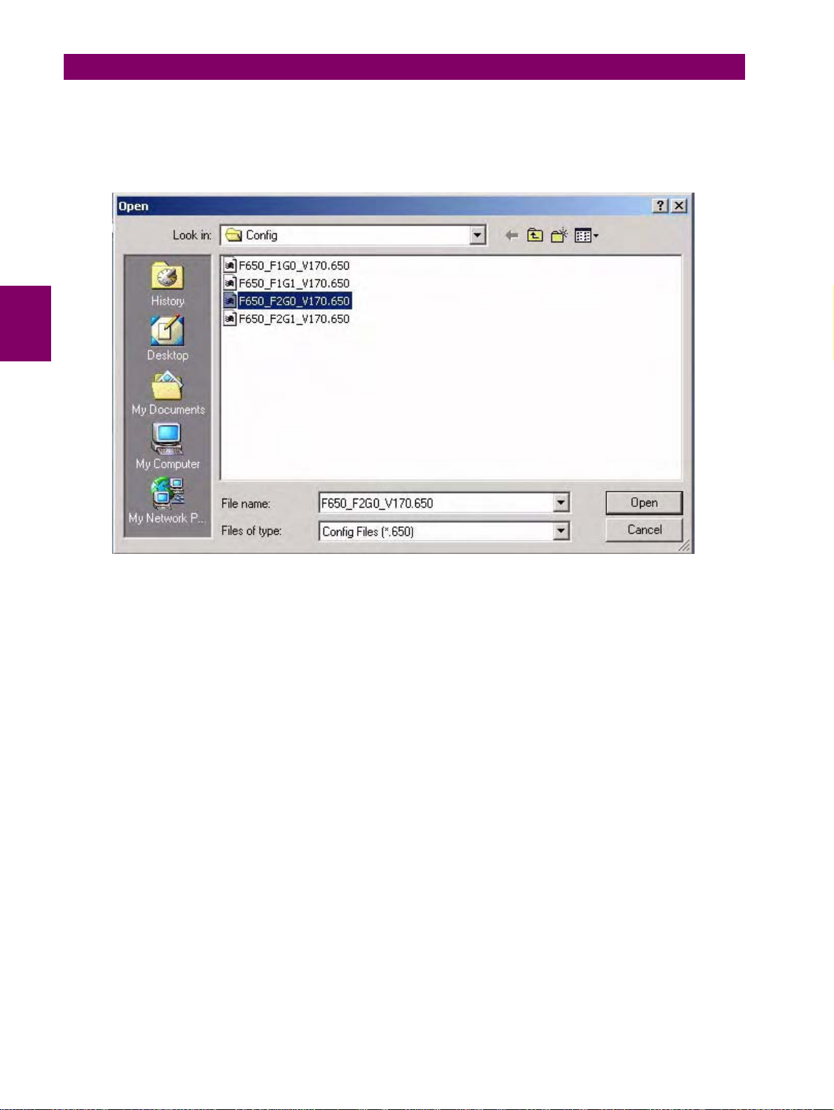
4.1 ENERVISTA 650 SETUP SOFTWARE INTERFACE 4 HUMAN INTERFACES. SETTINGS & ACTUAL VALUES
4.1.7.1 NEW, OPEN, SAVE, SAVE AS AND CLOSE
In these options, the program opens a dialog box (with default path to Files>Config program folder) where the setting and
configuration files can be selected for their “off-line” edition. For enabling access to this menu, there must be no
communication between the PC program and the relay.
Figure 4–5: OPEN FILE MENU
Once the *.650 file with the appropriated relay model (FXGX) is selected, the program will enable the off-line options to fully
program the unit. The enabled menus in the EnerVista 650 Setup program are: File, Setpoint, Actual, Communication, View
and Help.
The off-line mode displays the File, Setpoint, Actual, Communication, Security, View and Help submenus to program the
unit.
The Actual values submenus are for structure purposes only Values are not refreshed while the relay is not communicating.
The “Save as” and ”Close” submenus are used to save the *.650 file into the computer and to close the current file. To work
in off line mode for settings and configuration edition it is not necessary to use the ”Close” option, a new *.650 can be
opened without closing the previous one. The ”Close” option is used to clear all data in EnerVista 650 Setup program,
enabling ”Upgrade firmware version” and “Upgrade Operating system” options.
4-12 G650 Generator Protection & Control System GEK-113285A
Page 88
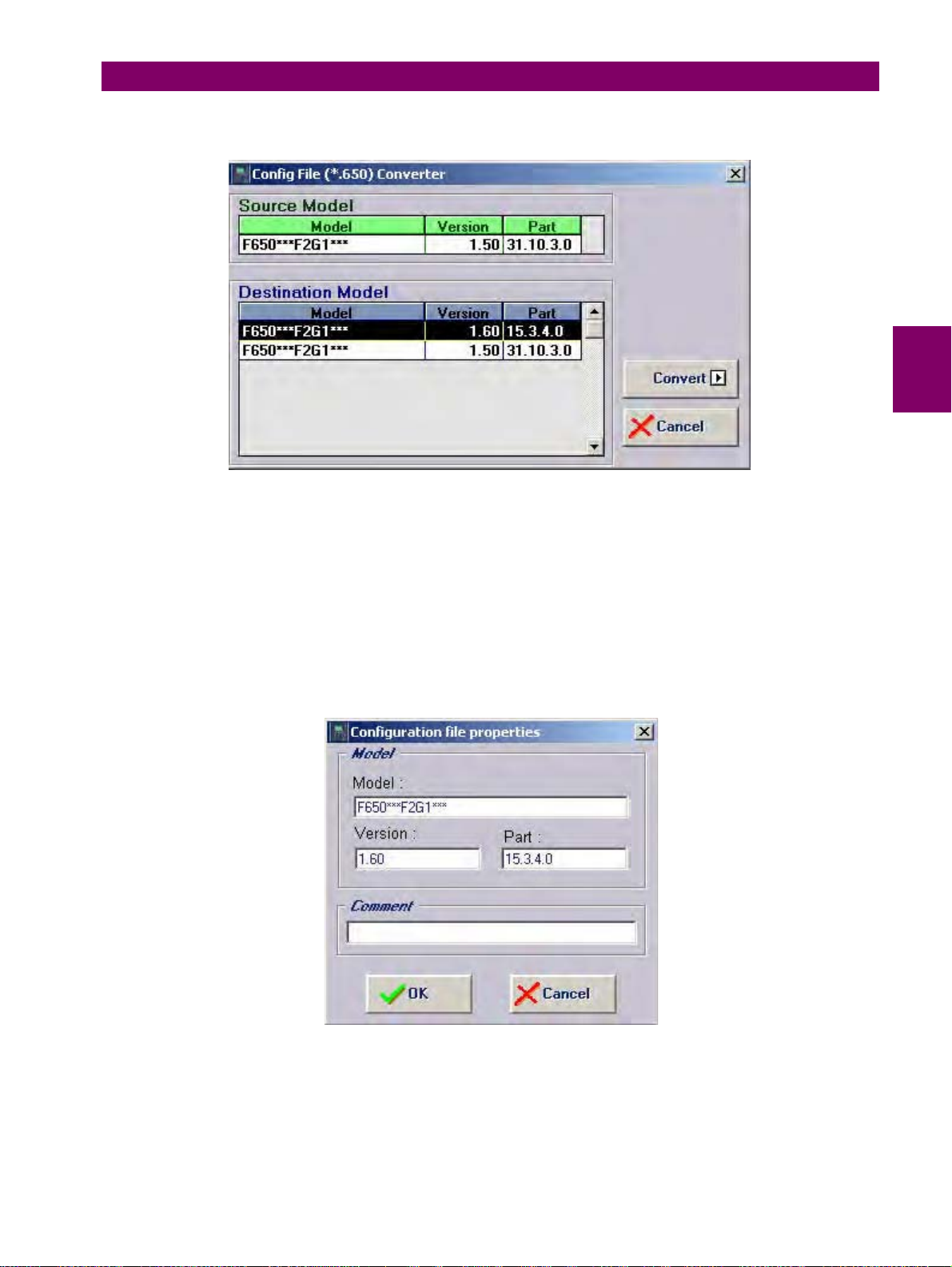
4 HUMAN INTERFACES. SETTINGS & ACTUAL VALUES 4.1 ENERVISTA 650 SETUP SOFTWARE INTERFACE
4.1.7.2 CONFIG FILE (*650) CONVERTER
Figure 4–6: CONFIG FILE (*650) CONVERTER MENU
This tool provides automatic conversion of configuration files from a firmware version to a previous or later version.
Open the source *.650 file and select the version and model to be converted to.
It is possible to change the model type (FXGX) using the conversion tool. It must be taken into account that part of the logic
can be readjusted to fit the new input and output boards selection. Notice also that the external wiring of inputs and outputs
board are different for type 1, 2, 4 and 5.
4
4.1.7.3 PROPERTIES
When this option is selected, the program will show a screen including the relay model information, firmware version, etc. of
the file being edited, as shown on Figure 4–7:
Figure 4–7: FILE PROPERTIES MENU
GEK-113285A G650 Generator Protection & Control System 4-13
Page 89
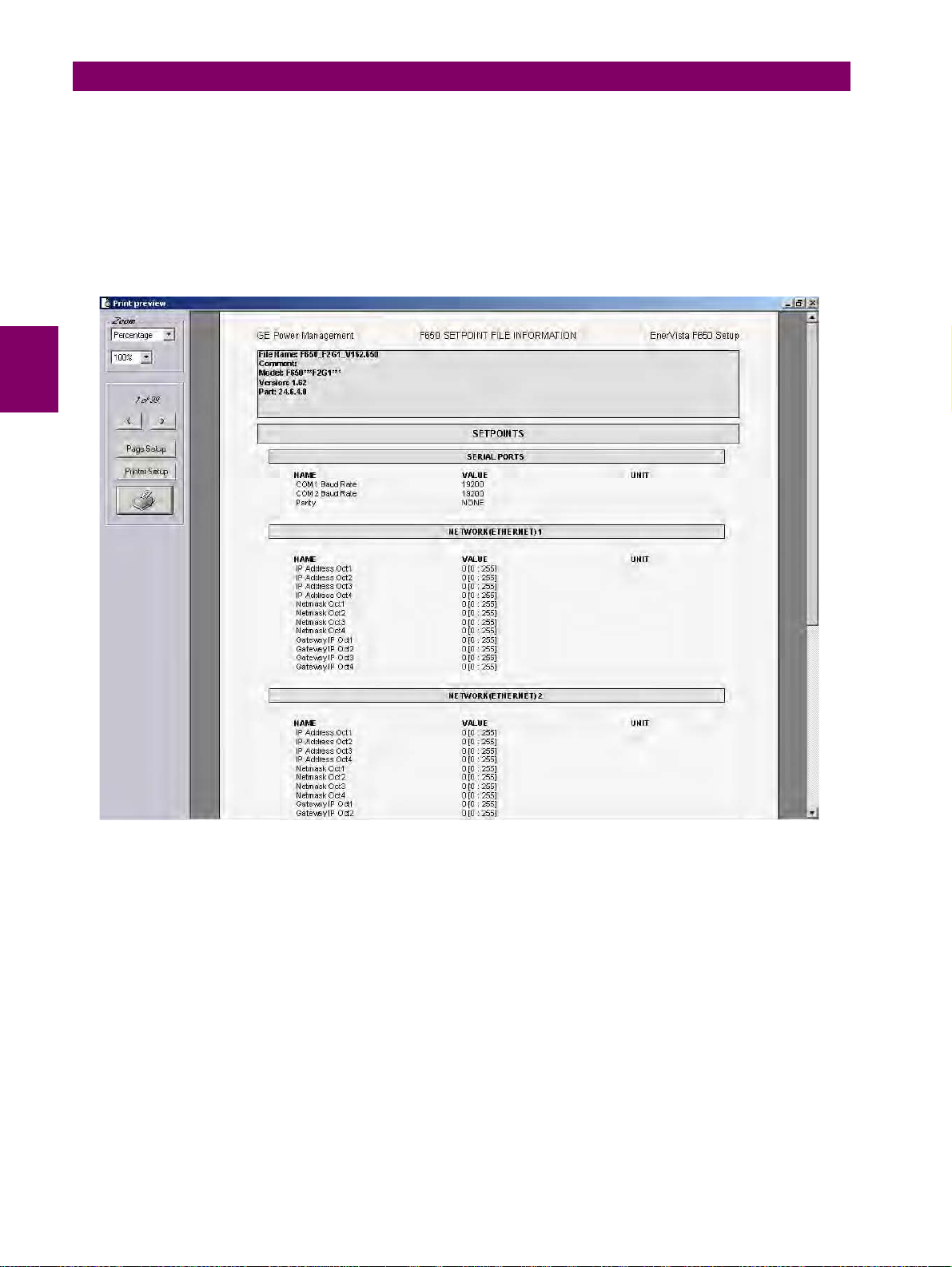
4.1 ENERVISTA 650 SETUP SOFTWARE INTERFACE 4 HUMAN INTERFACES. SETTINGS & ACTUAL VALUES
4.1.7.4 PRINTING OPTIONS (PRINT SETUP/PRINT PREVIEW/PRINT/PRINT TO FILE)
The printing options are active only in off-line mode, in “File edition”, and not in on-line mode, connected with the relay.
a) PRINT SETUP
Option to configure the printing options and settings for the printing device.
b) PRINT PREVIEW
Option to preview the whole settings and configuration file (*.650) in paper format to be printed as shown in Figure 4–8:
Figure 4–8: PRINT PREVIEW OF SETTINGS FILE
c) PRINT
In this option, the program will print the relay configuration using the PC default (active) printer on port COMx or LPT. This
option is active only in off-line mode, in file edition, and not in on-line mode, connected with the relay.
d) PRINT TO FILE (*XLS)
Possibility to export the configuration file to an Excel file using the “Print to file (*.xls)” option.
4-14 G650 Generator Protection & Control System GEK-113285A
Page 90
4 HUMAN INTERFACES. SETTINGS & ACTUAL VALUES 4.1 ENERVISTA 650 SETUP SOFTWARE INTERFACE
4.1.8 SETPOINT MENU OVERVIEW
Table 4–5: GENERAL OVERVIEW OF SETPOINT MENU IN ENERVISTA 650 SETUP:
SETPOINT
Product Setup
System Setup
Protection Elements
Control Elements
Inputs/Outputs Contact I/O settings for all boards available in device, Remote Comms.
Relay Configuration
Logic Configuration
61850 Configuration
Clock (*)
Options enabled only in On-line mode are marked as (*). Options enabled only in Off-line mode are marked as (**)
Communications settings for all protocols and physical mediums.
ModBus user map definition, fault report, oscillography, data logger and
demand settings.
General Settings, Flex Curves Definition, Breaker settings and
maintenance, and switchgear snapshot events management.
Phase, Neutral, Ground, Sensitive Ground and Negative Sequence
Current Settings. Voltage Elements settings and Power Settings
management.
Setting groups, under and overfrequency settings, autoreclose, breaker
failure VT fuse failure.
Configuration of Outputs, LEDs, Operations, Protection Elements,
Oscillography, Control Events, Switchgear, Inputs, Virtual Inputs,
Operations and HMI. Whole relay configuration with internal relay signals
or user-definable ones as logic (virtual outputs).
Logic configuration graphic editor (PLC Editor). It is a PLC Project file
editor that contains all the internal drawings used to make the logic
(virtual outputs) based on IEC 61131-3 standard. Functional block
diagram (FDB).
61850 Configuration tool. Only available for IEC61850 models (6) when
communicating through Ethernet with EnerVista 650 Setup.
Relay synchronization to computer clock or to user-definable date and
time. On-line mode only.
4
4.1.8.1 PRODUCT SETUP
Table 4–6: GENERAL OVERVIEW OF PRODUCT SETUP MENU:
PRODUCT
SETUP
Communication
Settings
ModBus User Map
Fault Report Fault report settings. Possibility to show fault reports on HMI screen.
Oscillography
Data Logger Data logger configuration
Demand
Options enabled only in On-line mode are marked as (*). Options enabled only in Off-line mode are marked as (**)
Serial Ports, Network (Ethernet), ModBus Protocol, DNP Slave, IEC 8705-104 and SNTP settings .
ModBus user map definition. The ModBus user map is formed by 256
records, selectable from the complete relay ModBus map.
Oscillography settings (trigger position, samples per cycle, etc.). The
trigger and digital channels (up to 16) must be configured in
“Setpoint>Relay configuration”.
Demand settings. The demand trigger and demand reset signals must be
configured in “Setpoint>Relay configuration”
a) COMMUNICATION SETTINGS
This section details the settings related to communication parameters for the different protocols available in the G650.
Table 4–7: GENERAL OVERVIEW OF COMMUNICATION SETTINGS MENU:
COMMUNICATION
SETTINGS
GEK-113285A G650 Generator Protection & Control System 4-15
Page 91
4.1 ENERVISTA 650 SETUP SOFTWARE INTERFACE 4 HUMAN INTERFACES. SETTINGS & ACTUAL VALUES
Serial Ports Baud rate and parity for COM1 and COM2 serial communication ports.
Ethernet communication parameters for COM3 (IP Address, Netmask,
Gateway IP)
Network (Ethernet)
ModBus Protocol
DNP3 Slave
IEC 870-5-104
SNTP (*) Synchronization over Ethernet settings
Options enabled only in On-line mode are marked as (*). Options enabled only in Off-line mode are marked as (**)
NOTE: The ModBus Slave address used by Ethernet ports is the one set
for COM2.EnerVista 650 Setup software allows programming two
different Ethernet addresses, but the first IP has always to be set as the
second IP Address is an Alias.
ModBus Slave Addresses for serial and Ethernet communication and the
ModBus port number used for ModBus TCP/IP
Physical port, Slave Address for DNP, IP Addresses for Masters, TCP/
UDP Port, Unsolicited Response parameters, Analog scale factors and
deadbands, message fragment size, Binary input block.Available for
standard and IEC61850 models.
TCP Port, Common Addr of ASDU, Cyclic Meter Period and,
Synchronization Event settings.Available for standard and IEC61850
models.
4.1.8.2 SYSTEM SETUP
This section shows the settings related to the system setup definition such as shown in the following table.
Table 4–8: GENERAL OVERVIEW OF SYSTEM SETUP MENU:
SYSTEM
SETUP
This screen describes and enables the settings of the power system
where the relay will operate. Some of these settings will be used only for
General Settings
Flex Curves
Breaker settings
Breaker maintenance
Switchgear Configuration of snapshot events for each switchgear (enable or disable)
metering values presentation purposes; however, some of them apply
directly to the sampling and analog-digital conversion process (rated
frequency setting). Therefore, these settings need to be adjusted so that
they fit the system settings.
Flex Curves – Programmable user curves: The relay incorporates 4 user
curves called Flex Curve A, B, C and D. The points for these curves are
defined by the user in “Setpoint>System Setup>Flex Curves>Edit
Curve” menu in EnerVista 650 Setup. User defined flex curves can be
selected as an operation curve in all the time overcurrent functions in the
relay.
Breaker settings, maintenance and switchgear selection of the device
configured as breaker in the G650. The selected switchgear will be used
in recloser, breaker failure and synchronism functions. The settings are
Number of Switchgear, Maximum KI
Openings, Max.Openings 1 hour and Snapshot Events.
These settings correspond to the initialization of (KI)
counting of number of openings and closings of the switchgear
configured as breaker. These Counters allow the breaker Maintenance.
They are used to cumulate the breaker ageing produced by a trip or a
breaker opening. In order to incorporate the breaker historic, in case of
existing breakers, the system allows assigning an initial value to
accumulated amperes, and to the number of opening and closing
operations.
2
t, KI2t Integ. Time, Maximum
2
t counters, and the
Options enabled only in On-line mode are marked as (*). Options enabled only in Off-line mode are marked as (**)
4.1.8.3 PROTECTION ELEMENTS
This option shows all the protection-grouped elements available in the relay as shown in Table 4–9:. Each of these groups
includes the specific protection units of the same type. For example phase currents group includes TOC, IOC, directional
units, etc. There are three groups available, so there are three protection units of each function that can work in grouped
mode or ungrouped (altogether).
4-16 G650 Generator Protection & Control System GEK-113285A
Page 92
4 HUMAN INTERFACES. SETTINGS & ACTUAL VALUES 4.1 ENERVISTA 650 SETUP SOFTWARE INTERFACE
Table 4–9: GENERAL OVERVIEW OF PROTECTION ELEMENTS MENU:
PROTECTION
ELEMENTS
Phase Current All overcurrent grouped functions for phase current.
Neutral Current
Ground Current
Sensitive Ground
Current
Negative Sequence
Current
Voltage Elements
Power All power grouped protection functions.
Options enabled only in On-line mode are marked as (*). Options enabled only in Off-line mode are marked as (**)
All overcurrent grouped functions for neutral current. (Calculated from
phases, not measured)
All overcurrent grouped functions for ground current. (Measured from 4
current input)
All overcurrent grouped functions for sensitive ground current.
(Measured from 5
All Negative sequence
All voltage grouped functions for phases, neutral, ground and auxiliary
voltage
th
current input)
overcurrent grouped functions.
th
4
GEK-113285A G650 Generator Protection & Control System 4-17
Page 93
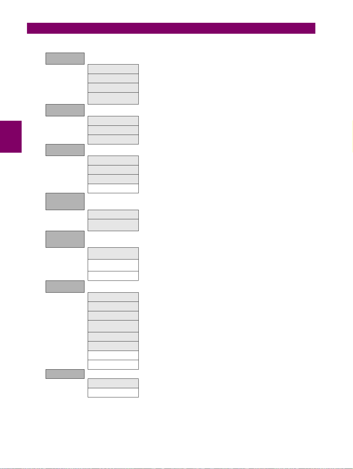
4.1 ENERVISTA 650 SETUP SOFTWARE INTERFACE 4 HUMAN INTERFACES. SETTINGS & ACTUAL VALUES
Table 4–10: PROTECTION ELEMENTS INCLUDED
PHASE
CURRENT
Phase TOC High Phase time overcurrent, high level (51PH)
Phase TOC Low Phase time overcurrent, low level (51PL)
Phase IOC High Phase instantaneous overcurrent, high level (50PH)
NEUTRAL
CURRENT
GROUND
CURRENT
SENSITIVE
GROUND
CURRENT
NEGATIVE
SEQUENCE
CURRENT
VOLTAGE
ELEMENTS
POWER
Generator Thermal
Model
Neutral TOC Neutral time overcurrent (51N)
Neutral IOC Neutral instantaneous overcurrent (50N)
Neutral Directional Neutral directional unit (67N). Voltage, current and dual polarization.
Ground TOC Ground time overcurrent (51G)
Ground IOC Ground instantaneous overcurrent (50G)
Ground Directional Ground directional unit (67G). Voltage, current and dual polarization.
Restricted Gnd Fault Restricted Ground Fault (87G). Enhanced models only.
Sensitive Ground TOC Sensitive ground time overcurrent (51SG)Enhanced models only.
Sensitive Ground IOC
Negative Sequence
TOC
Negative Sequence
IOC
Generator Unbalance Generator current unbalance (46)
Phase UV Phase undervoltage (27P)
Phase OV Phase overvoltage (59P)
Neutral OV High Neutral overvoltage, high level (59NH)
Negative Sequence
OV
Auxiliary OV Auxiliary overvoltage (59X)
Auxiliary UV Auxiliary undervoltage (27X)
Volts per Hertz Volts per Hertz (24). Enhanced models only.
Ground OV Ground Overvoltage (59G)
Directional Power Directional power (32), in primary values.
Pwr Factor Limiting Power Factor Limiting (55). Enhanced models only.
Thermal model or Thermal image unit for phases (49S)
Sensitive ground instantaneous overcurrent (50SG). Enhanced models
only.
Negative sequence time overcurrent (51-2)
Negative sequence instantaneous overcurrent (50-2)
Negative sequence overvoltage (47). Phase reversal
4-18 G650 Generator Protection & Control System GEK-113285A
Page 94
4 HUMAN INTERFACES. SETTINGS & ACTUAL VALUES 4.1 ENERVISTA 650 SETUP SOFTWARE INTERFACE
4.1.8.4 CONTROL ELEMENTS
This option shows all the control elements available in the relay as shown in Table 4–11:. Some of the elements are
grouped ones such as underfrequency, overfrequency and broken conductor.
Table 4–11: GENERAL OVERVIEW OF CONTROL ELEMENTS MENU:
CONTROL
ELEMENTS
G650 units incorporate a flexible grouping capability for protection units.
This means that protection units can be used in either single setting
group (default mode-all units can operate simultaneously) or three
setting groups (in this mode, protection units are grouped in three
Setting Group
Underfrequency Underfrequency unit (81U). Grouped element
Overfrequency Overfrequency unit (81O). Grouped element
Synchrocheck Synchronism check unit (25). Not grouped, a single unit provided
Breaker Failure
VT Fuse Failure
Pulse Counters Pulse counters function. 8 counters provided.
Analog Comparators Analog comparator function. 20 analog comparators provided.
Frequency rate of
change
Loss of Mains Loss of Mains (78V). Grouped element. Enhanced models only.
Loss of Excitation Loss of Field (40). Grouped element
Accidental
Energization
independent tables, with only one of them active at a given time).
Protection element grouping involves only Protection elements together
with broken conductor detection and over and under frequency, which
are usually considered as control elements. The rest of control elements
such as fuse failure, breaker failure, synchronism, and breaker settings
are not involved in the tabled groups concept.
Breaker failure (50BF). Not grouped, a single unit provided. Enhanced
models only.
Fuse Failure (VTFF). Not grouped, a single unit provided. Enhanced
models only.
Frequency rate of change function (81R).Grouped element.
Inadvertent generator energization (50/27). Grouped element
4
4.1.8.5 INPUT/OUTPUTS
Section that contains the settings for all input and output boards and the Force Outputs and Virtual inputs activation tools.
Table 4–12: GENERAL OVERVIEW OF “INPUTS/OUTPUTS” SETTINGS MENU.
INPUTS/
OUTPUTS
Contact I/O
Force Outputs (*)
Virtual Inputs (*)
Options enabled only in On-line mode are marked as (*). Options enabled only in Off-line mode are marked as (**)
Inputs and outputs settings for all boards in G650. The I/O settings
configuration can only be performed through EnerVista 650 Setup, not
HMI available.
This menu allows activating each contact output in the relay, to facilitate
maintenance testing. On line mode only.
This menu allows operating virtual inputs. These variables are used as
inputs to logic schemes configured in the relay. Virtual inputs can be
operated in a latched mode (32 latched virtual inputs) or in Self-reset
mode (32 self reset virtual inputs).
This section shows the settings related to inputs and outputs for the different boards available in G650 (F, G, H, J).
Table 4–13: GENERAL OVERVIEW OF “INPUTS/OUTPUTS>CONTACT I/O” SETTINGS MENU.
CONTACT I/O
GEK-113285A G650 Generator Protection & Control System 4-19
Page 95
4.1 ENERVISTA 650 SETUP SOFTWARE INTERFACE 4 HUMAN INTERFACES. SETTINGS & ACTUAL VALUES
Board F Board located in first slot, always connected.
Board G
Board H Board located in first slot of CIO Module (external inputs/outputs module)
Board J
Board located in second slot, depends on model definition. If model is
type G0 there is no board in second slot.
Board located in second slot of CIO Module (external inputs/outputs
module)
4.1.8.6 RELAY CONFIGURATION
This is the relay configuration section in which the relay can be configured using internal states or already compiled
equation on PLC Editor.
Table 4–14: GENERAL OVERVIEW OF RELAY CONFIGURATION MENU:
RELAY CONFIG
Outputs Configuration of contact output operate and reset signals for all boards.
LEDs
Operations
Protection Elements
Oscillography
Control Events
Switchgear
Inputs
Virtual Inputs
MMI (HMI-Human
Machine Interface)
15 LEDs fully configurable from any logical variable, contact or virtual
input. First 5
can be latched through PLC configuration. From the LED configuration
screen, it is possible to print the vertical LED label for the relay.
Configurable operations up to 24. Operation texts, interlocks, final states,
frontal keys, time outs and masters.
This tab allows assigning operands (logic signals) as inputs to different
protection elements. To block, reset, initiate the different protection
elements inputs.
Trigger and up to 16 digital channels to be included in oscillography
records, are programmable from any logical variable, contact or virtual
input. Text configuration is only for off-line mode.
NOTE: This screen is used for the configuration of digital channels and
oscillography trigger. The rest of parameters, such as function enabling/
disabling, sampling rate, number of oscillography files, etc. must be set
on the Setpoint>Product Setup>Oscillography menu.
Up to 128 user programmable events from any logical variable, contact
or virtual input. Possibility to display the event as an alarm on the alarms
panel. Control events are also displayed in the snapshot events
recording. 1 ms time tagging.
A control event is a logic signal associated to an operand or combination
of operands, that allows following the status of that signal.
Up to 16 configurable switchgear elements. A switchgear element can be
a breaker, a line selector switch, a grounding selector switch, a busbar
selector switch, etc. This screen allows configuration of type of contacts,
opening and closing time, contact assignation and text for events related
to switchgear. There are 64 pre-established events for switchgear, which
correspond to opening, closing, Error01 and Error11 of the 16
programmable switchgear elements.
Text configuration for off-line mode file management for all the contact
inputs available in device.
Text configuration for off-line mode file management. 32 latched and 32
self reset virtual inputs.
Screen for one line diagram configuration. This menu shows a scenario
to draw a simplified one-line diagram of a bay in a feeder, line,
transformer, etc. The menu includes a library for power elements,
metering elements, text and drawings. See an example in
LEDs are latched by hardware, the rest are self-reset but
4-20 G650 Generator Protection & Control System GEK-113285A
Page 96
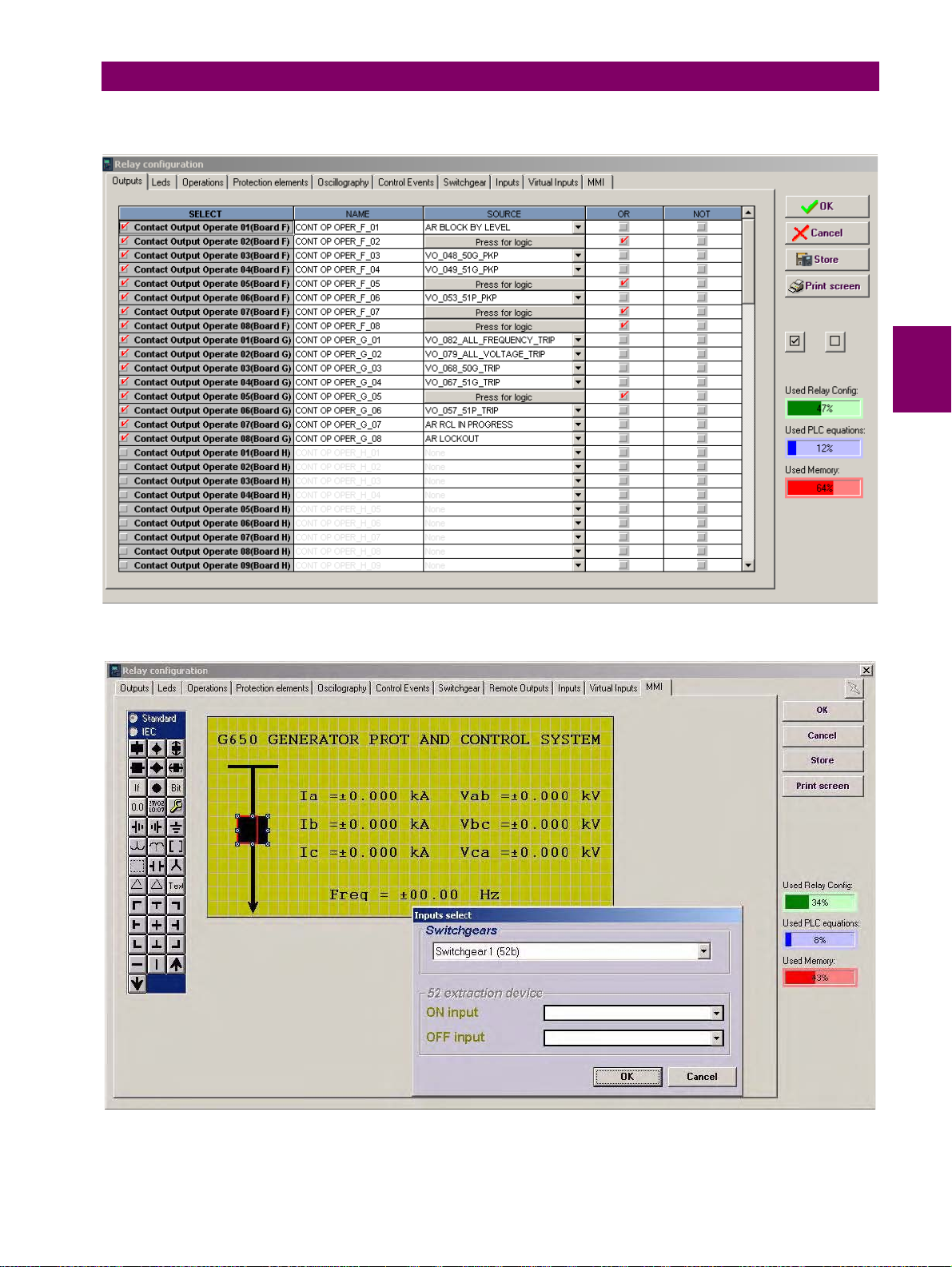
4 HUMAN INTERFACES. SETTINGS & ACTUAL VALUES 4.1 ENERVISTA 650 SETUP SOFTWARE INTERFACE
The following figures show an example of the default factory configuration for G650:
4
Figure 4–9: RELAY CONFIGURATION
GEK-113285A G650 Generator Protection & Control System 4-21
Page 97
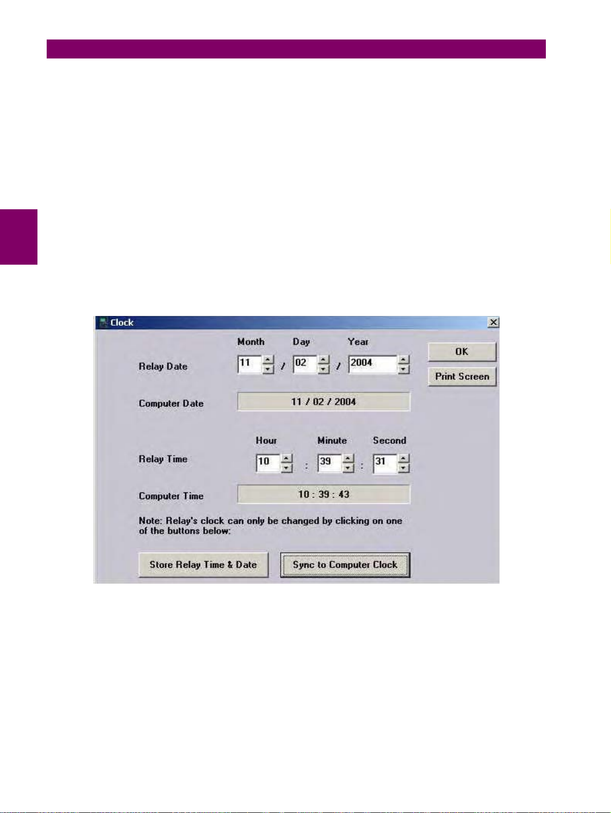
4.1 ENERVISTA 650 SETUP SOFTWARE INTERFACE 4 HUMAN INTERFACES. SETTINGS & ACTUAL VALUES
Figure 4–10: HMI CONFIGURATION
4.1.8.7 LOGIC CONFIGURATION
This logic configuration allows creating more complex configurations, using the graphical PLC, than using the tables from
Relay Configuration. For file management detailed information go to section 4.1.5.
File description:
*.pep: Header for Logic project: PLC project file containing the necessary information relative to the relay model, logic
libraries included in the project (*.lib), graphic file name (*.aut), etc.
*.aut: PLC Project file containing all the drawings used by the logic, required by 650 relay based on IEC 61131-3
standard. Functional block diagram (FDB).
*.lib: User programmable logic objects: Library file to be included as an object in a PLC project. Logic packages that
can be stored into libraries and be distributed in different PLC projects.
4.1.8.8 CLOCK
This menu allows to update the date and time of the relay, either synchronizing them with the PC clock, or entering the
information manually.
Figure 4–11: CLOCK
4-22 G650 Generator Protection & Control System GEK-113285A
Page 98
4 HUMAN INTERFACES. SETTINGS & ACTUAL VALUES 4.1 ENERVISTA 650 SETUP SOFTWARE INTERFACE
4.1.9 ACTUAL VALUES MENU OVERVIEW
The menu bar in the main screen of EnerVista 650 Setup software shows the ACTUAL menu option. This option
concentrates and displays all the status of protection, control elements, metering, counters information, oscillography,
events, fault locator, etc. This section shows only the structure of menus in EnerVista 650 Setup.
Table 4–15: GENERAL OVERVIEW OF ACTUAL VALUES MAIN MENU:
ACTUAL
Front Panel The relay front LEDs status is shown on this menu.
Status
Metering
Inputs/Outputs
Records
Protection and control status signals for all available protection functions
in device.
All metering values available in device. Primary and secondary values,
frequency and phasor diagram provided.
All input and output status provided. For contact inputs and contact
outputs as well as virtual input and virtual output signals.
Only enabled in on line mode, retrieval of all the available records in
device. Snapshot events, control events, oscillography and fault reports.
4.1.9.1 FRONT PANEL
The front panel menu shows only the LEDs submenu where all the front LEDs can be monitored.
4.1.9.2 STATUS
The following menu includes all the available protection status in the device.
4
Table 4–16: GENERAL OVERVIEW OF STATUS MENU:
STATUS
Operation bits
Breaker
Protection Status of all the protection units in the device.
Control Elements Status of all the control units available in the device.
Protection Summary
Snapshots events
summary
ModBus User Map
Switchgear Status
Calibration
Flex Curves
System Info
Records Status
SNTP-IRIG-B Information related to synchronization via IRIG_B or SNTP
Up to 24 elements. OPERATION BIT XX is (0) when the configured time
out for the operation XX expires or when success conditions are met.
And it is (1) if operation XX is executed and interlocks are fulfilled.
Breaker status (open, closed or undefined). The rest of the status signals
corresponding to the switchgear XX configured as breaker are in the
“Status>Switchgear Status>Switchgear XX” menu.
This screen shows a complete list of all protection and control elements
in the relay, showing their status (enabled or not).
Summary of the snapshot events status (enabled or disabled) for
protection, control, inputs and outputs boards and switchgear.
Up to 256 elements. Value in SIGNED INT 16 BIT format of the reading
for the selected address configured in “Setpoint>Product
Setup>ModBus User Map”
Up to 16 blocks of switchgear status signals for the 16 configurable
devices. Status signals such as inputs for A and B contacts, status for A
and B, open and close status, error 00 and error 11, open init and close
init, fail to open and fail to close signals.
Internal states for calibration. Factory calibration and calibration error
signals.
Flex curve status for A, B, C and D user curves. (0) if it is not configured,
(1) if it is configured. To configure a flex curve go to “Setpoint>System
Setup>Flex Curves” menu.
This screen can monitor the system parameters and the internal status of
the Relay operative system. Not enabled by default, password required
Information related to the different records stored in the Relay, such as:
Fault reports, control events, oscillography, data logger, demand, energy,
and breaker maintenance.
GEK-113285A G650 Generator Protection & Control System 4-23
Page 99
4.1 ENERVISTA 650 SETUP SOFTWARE INTERFACE 4 HUMAN INTERFACES. SETTINGS & ACTUAL VALUES
T able 4–17: ACTUAL VALUES INCLUDED IN THE PROTECTION MENU
PROTECTION
Protection Blocks This screen shows all the protection element blocks available. Protection
Phase Current Protection status signals (pickups and operations) for time overcurrent,
Neutral Current Protection status signals (pickups and operations) for time overcurrent,
Ground Current Protection status signals (pickups and operations) for time overcurrent,
Sensitive Ground
Current
Negative Sequence
Current
Voltage Protection status signals (pickups and operations) for all voltage
Power Protection status signals (pickups and operations) for all power units .
elements block signals can be configured at “Setpoint>Relay
Configuration > Protection Elements”.
instantaneous overcurrent and directional protection functions for phase
current.
instantaneous overcurrent and directional protection functions for neutral
current (calculated from phases).
instantaneous overcurrent and directional protection functions for ground
current (measured from 4
Protection status signals (pickups and operations) for time overcurrent,
instantaneous overcurrent, isolated and directional protection functions
for ground current (measured from 5
Protection status signals (pickups and operations) for negative sequence
time overcurrent function.
functions, undervoltage, overvoltage, neutral overvoltage, negative
sequence overvoltage and auxiliary under and over voltage, Volts/Hz and
ground overvoltage.
th
current input).
th
current input).
Table 4–18: DIFFERENT CONTROL ACTUAL VALUES INCLUDED IN THE CONTROL ELEMENTS MENU
CONTROL
ELEMENTS
Frequency Status signals (pickups and operations) for under, overfrequency and
Synchrocheck Status signals for synchrocheck function (25).
Breaker Failure Status signals for breaker failure function (50BF). Enhanced models only.
VT Fuse Failure Fuse failure detection signal. Enhanced models only.
Setting Groups Status signals (activations and blocks) for the relay setting group change.
Pulse Counters Status signals for pulse counters units.
Analog Comparator Status signals for analog comparator units.
Loss of Mains
Loss of excitation Status signals (pickups and operations) for loss of excitation (40).
Accidental
Energization
frequency rate of change units.
By default the “setting group” setting is disabled and all the grouped
elements can be enabled at the same time.
Status signals (operations) for loss of mains (78V).
only.
Status signals (off-line, armed and operation) for inadvertent generator
energization (50/27).
Enhanced models
4-24 G650 Generator Protection & Control System GEK-113285A
Page 100
4 HUMAN INTERFACES. SETTINGS & ACTUAL VALUES 4.1 ENERVISTA 650 SETUP SOFTWARE INTERFACE
T able 4–19: ACTUAL VALUES RELATED TO RECORDING FUNCTIONS IN THE RECORDS STATUS MENU:
RECORD
STATUS
Fault Reports This menu shows the fault report status signals, as fault report trigger,
Control Events Status of the control events (if the signal configured to launch the control
Oscillography Status of signals related to oscillography recording, such as status or
Data Logger Data logger information about oldest and newest sample time stamp,
Demand Demand trigger and reset inputs status.
Energy Freeze, unfreeze and reset input signals for energy counters.
Breaker Maintenance All signals related to breaker maintenance, such as number of openings,
fault date, fault type and location, besides the fault report number.
event is active or not).
digital channels, oscillography trigger, number of records available, etc.
and number of channels and days configured in data logger settings.
2
closings, (KI)
t counters, alarm signal for (KI)2t, etc.
4.1.9.3 METERING
The Metering menu includes all the measurements available in the device. Primary and secondary values, and also the
data related to the recording functions in the relay.
Table 4–20: GENERAL OVERVIEW OF METERING MENU:
METERING
Primary Values Primary values measurements for currents, voltages, power, energy and
Secondary Values Secondary values measurements for currents, voltages and power.
Phasor Diagram Current, voltage and sequence components.
Frequency Line and Bus frequencies.
demand
4
4.1.9.4 INPUTS/OUTPUTS
The Inputs/Outputs menu includes all the inputs and outputs signals available in the device. Contact and virtual type.
Table 4–21: GENERAL OVERVIEW OF INPUTS/OUTPUTS MENU:
INPUTS/
OUTPUTS
Contact Inputs Status of digital inputs in the Relay for each board according to the relay
Contact Output Status Status of digital outputs in the Relay for each board according to the relay
Contact Outputs
Operates
Contact Outputs
Resets
IO Board Status Status of I/O boards. This status provides if the hardware it is OK (boards
Virtual Inputs Status of Virtual inputs latched (32) and self-reset (32).
Virtual Outputs Status of virtual outputs (configured in PLC Editor). Up to 512.
Analog Inputs Measurements coming from analog inputs (DCMA)
Options enabled only in On-line mode are marked as (*). Options enabled only in Off-line mode are marked as (**)
model.
model.
Status (activated or not) of the variables used to operate a contact
output. To configure these signals go to “Setpoint>Relay
Configuration>Outputs” menu.
Status (activated or not) of the variables used to reset a contact output.
To configure these signals go to “Setpoint>Relay Configuration>Outputs”
menu. This output reset Command will only be effective if the “latch”
option has been Selected for the “Output Type” setting on the I/O board,
thus when the contact output has been configured to emulate function 86
(latching relay).
matching relay model, correctly inserted in their tracks, in good state and
communicating through the internal CAN Bus).
GEK-113285A G650 Generator Protection & Control System 4-25
 Loading...