

Page 1

Consumer Home Services Training
TECHNICAL SERVICE GUIDE
TMNF 20 Cubic Foot
GE Refrigerators
MODEL SERIES:
GTRS0
GTRC0
GTRL0
MTRL0
PUB #01-2010
Page 2

Page 3

– 1 –
!
IMPORTANT SAFETY NOTICE
The information in this service guide is intended for use by
individuals possessing adequate backgrounds of electrical,
electronic, and mechanical experience. Any attempt to repair a
major appliance may result in personal injur y and proper ty
damage. The manufacturer or seller cannot be responsible for the
interpretation of this information, nor can it assume any liability in
connection with its use.
WARNING
To avoid personal injury, disconnect power before servicing this
product. If electrical power is required for diagnosis or test
purposes, disconnect the power immediately after performing the
necessary checks.
RECONNECT ALL GROUNDING DEVICES
If grounding wires, screws, straps, clips, nuts, or washers used to
complete a path to ground are removed for service, they must be
returned to their original position and properly fastened.
Page 4
– 2 –
20
TOP MOUNT GE™
DISCONNECT POWER CORD BEFORE SERVICING
IMPORTANT - RECONNECT ALL
All
parts of this
rent are grounded.
or
washers
for service, they must be
properly
appliance capable
If
used to complete a path to ground are r
fastened.
grounding wires, scr
GROUNDING DE
returned
of conducting
to their original position and
VICES
electrical
ews, straps,
ELECTRICAL
T
emperature
Defrost Control (w/no door openings)
Overtemperature
Electrical Rating:
Maximum
Maximum Ground Path Resistance .............................................
NO LOAD
Control Position 5/5 and Ambient of 70°F to 90°F
Fresh Food, °F
Frozen Food, °F
Run
Time, % @ 70°F
Run
Time, % @ 90°F
SPECIFICATIONS
Control (P
Current
osition FF/FZ)
Thermostat
115V AC
Leakage
...................................................
.............................
..............................................................
60 Hz
.....................................................
..................................................................
PERFORMANCE
............................................................................................ 34
............................................................................................. -3
.................................................................................. 20
.................................................................................. 40
AIR FLOW
EVAPORATOR
COLD
MIXED AIR
AIR RE
EVAPORATOR
AIR
TURN TO
FREEZE R
FRESH
FOOD
.105”
T
echnical Data
IMPORTANT SAFETY NOTICE
This
cur-
clips, nuts
emoved
information is intended for use by individuals
adequate backgrounds
experience. Any
in personal injury and pr
seller cannot be responsible for the
tion, nor can it
10hrs @ 35 min
37/0°F
63-57°F
11.6 Amp
0.75
0.14 Ohms
to 40
to 3F
to 40
to 70
REFRIGERATION SY
Compressor
Minimum Compressor Capacity
Minimum Equalized Pr
mA
@ 70°F
PSIG
@ 90°F
PSIG
REFRIGERANT
20
TMNF
TO
CABINET
WIRING
ORANGE
REV. 0
of electrical, electronic
attempt
assume
...........................................................................................
.................................................................................................
.................................................................................................
CHARGE
models
................................................................................
to repair a
operty damage.
any
liability
STEM
essure
(R134a)
.............................................. 22 inches Hg
major
interpretation
in
238C4518P001
possessing
and mechanical
appliance may result
The
manufacturer or
connection
of
with its
BLACK
GREEN/YELLOW
COMPRESSOR
OUND
GR
this
700
4.00
informa-
use.
BTU/hr
40 to 45
48 to 60
ounces
Page 5
– 3 –
Page 6

– 4 –
20
TOP MOUNT GE™
ELECTRONIC
DISCONNECT POWER CORD BEFORE SERVICING
IMPORTANT - RECONNECT ALL
All
parts of this
rent are grounded.
or
washers
for service, they must be
properly
appliance capable
If
grounding wires, scr
used to complete a path to ground are r
fastened.
GROUNDING DE
returned
of conducting
to their original position and
ELECTRICAL
T
emperature
Defrost Control (w/no door openings)
Thermistor kilo-ohm r
.............................................................................................................
.............................................................................................................
Overtemperature
Defrost Thermistor
Electrical Rating:
Maximum Current Leakage
Maximum Ground Path Resistance .............................................
NO LOAD
Control Position 5/5 and Ambient of 70°F to 90°F
Fresh Food, °F
Frozen Food, °F
Run
Time, % @ 70°F
Run
Time, % @ 90°F
SPECIFICATIONS
Control (P
osition FF/FZ)
esistance
Thermostat
.............................................................................................
115V AC
...................................................
.............................
............................................. @0°F
..............................................................
60 Hz
.....................................................
..................................................................
PERFORMANCE
............................................................................................ 34
............................................................................................. -3
.................................................................................. 15
.................................................................................. 30
VICES
electrical
ews, straps,
@37°F
@77°F
AIR FLOW
EVAPORATOR
COLD
MIXED AIR
AIR RE
EVAPORATOR
AIR
TURN TO
FREEZE R
FRESH
FOOD
.105”
T
echnical Data
IMPORTANT SAFETY NOTICE
This
cur-
clips, nuts
emoved
information is intended for use by individuals
adequate backgrounds
experience. Any
in personal injury and pr
seller cannot be responsible for the
tion, nor can it
96hrs @ 35 min
37/0°F
..........
42.7
..........
14.3
.............
5.0
69-59°F
34°F
11.6 Amp
0.75 mA
0.14 Ohms
to 40
to 3F
to 40
to 60
REFRIGERATION SY
Compressor 20 - 22 Models
Minimum Compressor Capacity
Minimum Equalized Pr
@ 70°F
PSIG
@ 90°F
PSIG
REFRIGERANT
20 models
TO
CABINET
WIRING
ORANGE
of electrical, electronic
attempt
assume
................................................................................................
.................................................................................................
CHARGE
................................................................................................
to repair a
operty damage.
any
liability
STEM
..........................................................
essure
(R134a)
major
interpretation
in
.............................................. 22 inches Hg
238C4518P002
possessing
and mechanical
appliance may result
The
manufacturer or
of
connection
this
with its
BLACK
GREEN/YELLOW
COMPRESSOR
OUND
GR
informa-
use.
803
BTU/hr
40 to 45
48 to 60
4.0
ounces
Page 7
– 5 –
MODEL NOMENCLATURE
Model series GTRS0, GTRC0, GTRL0, MTRL0 20-cubic foot refrigerators,
Page 8

– 6 –
F -
Flat
L - Left door swing
WW - White
on
white
T =Top Freezer
G = GE
M = Moffat
Configuration
Exterior
C=Color
F=High Gloss
L=Laminate
S=Stainless S teel
Volume
0 = 20 ft
Model Year
Z=201 0
Engineering Nomenclature
A=Initial Design
B=1stRevisio n
C=2nd Revision
D=3rd Revision
Etc.
Door Type / Special
Characters
L=Left Door Swing
R= Right Door Swing
K= Conv ersion Kit Mod el
<SPACE>
P T S C 0 L H Z A R W W
Interior/Shelves
Brand/Product
Depth/Power
C=Custom Style
H=Energy Star
L=Clean Steel
R=Canadá
S=Standard Depth
TM
F= Superior Wire Shelves
G=Standar d Glass Shelves
H=Upgrade Glass Shelves
I=Deluxe Glass Shelves
J=Spill Proof Glass/2 Split/1 FW
K=Spill-Proo f Glass Shelves 4-Split L=
Spill-Proo f/Slid e-Out GlassShelves
M=Spill-Proof/Slide-Out G lass & Quic k
Space Shalves
Icemaker/Exterior
A=Not Ice Maker Ready
B= Ice Maker Ready
C= Factory Ice Maker
D=Filter Ready/Ice Maker
E=6 Month Filter/Ice Mak er
F=1 Year Filter/Ice Maker*
(*Profi le CS has Ext Dips / Crush ed
/Cub ed/Wate r/ 6 Month Filter)
G=Intern al Water Dispenser/ Filter
Ready/ Ice Maker
H=Intern al Water Dispenser/ 6
Month Filter / Ice Maker
I=Inter nal Water Dispenser/ 1 Year
Filter / Ice Maker
AA - Almond on almond
R - Right door swing
Exterior Color /Special
BB=Black / Black
BB - Black on black
BS=Stainless / Black Case,
CC - Bisque on Bisque
Handles
CC=Bisqu e / Bisqu e
WH - White on black
CS = Clean Steel / Black Case,
AD - Almond on Black
Handles
LB = Clean steel/Black Handles
SS=Stainless / Stainless
Appea rance Handl
Features
Page 9

– 7 –
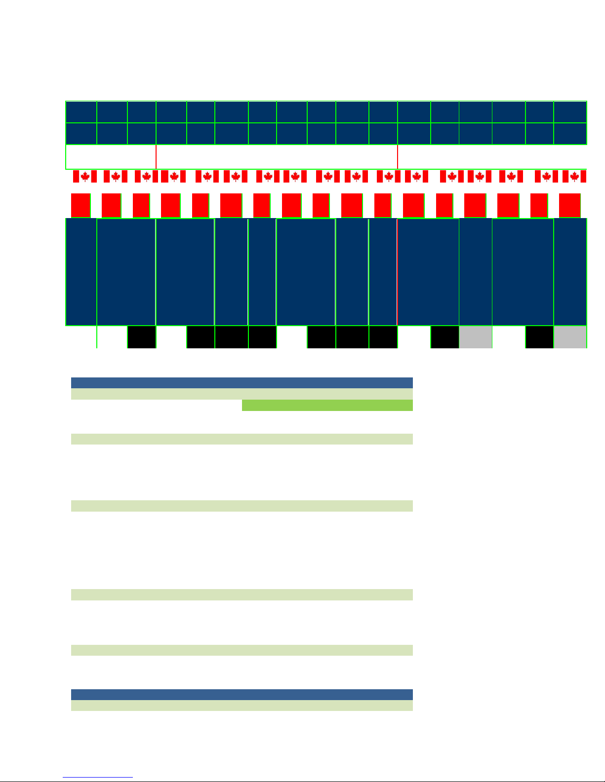
SERIAL NUMBERS
The serial numbers for General Electric refrigerators consists of two letters, followed by six
numerals. The two prefix letters of the serial number indicate the month and year the product was
manufactured. The year of manufacture does not correspond with the model year of the model
number.
JAN
FEB
MAR
APR
MAY
JUN
JUL
AUG
SEP
OCT
NOV
DEC
2000
2001
2002
2003
2004
2005
2006
2007
2008
2009
2010
2011
2012
2013
2014
2015
2016
2017
2018
2019
2020
2021
2022
AA
AD
AF
AG
AH
AL
AM
AR
AS
AS
AT
AV
AZ
AA
AD
AF
AG
AH
AL
AM
AR
AS
Refrigerators using a number four (4) as the first digit of the serial number are designated as
Celaya production.
AZ
DZ
DA
DD
DF
DG
DH
DL
DM
DR
DS
DS
DT
DV
DZ
DA
DD
DF
DG
DH
DL
DM
DR
DS
FZ
FA
FD
FF
FG
FH
FL
FM
FR
FD
FD
FT
FV
FZ
FA
FD
FF
FG
FH
FL
FM
FR
FD
GZ
GA
GD
GF
GG
GH
GL
GM
GR
GS
GS
GT
GV
GZ
GA
GD
GF
GG
GH
GL
GM
GR
GS
HZ
HA
HD
HF
HG
HH
HL
HM
HR
HS
HS
HT
HV
HZ
HA
HD
HF
HG
HH
HL
HM
HR
HS
LZ
LA
LD
LF
LG
LH
LL
LM
LR
LS
LS
LT
LV
LZ
LA
LD
LF
LG
LH
LL
LM
LR
LS
MZ
MA
MD
MF
MG
MH
ML
MM
MR
MS
MS
MT
MV
MZ
MA
MD
MF
MG
MH
ML
MM
MR
MS
RZ
RA
RD
RF
RG
RH
RL
RM
RR
RS
RS
RT
RV
RZ
RA
RD
RF
RG
RH
RL
RM
RR
RS
SZ
SA
SD
SF
SG
SH
SL
SM
SR
SS
SS
ST
SV
SZ
SA
SD
SF
SG
SH
SL
SM
SR
SS
TZ
TA
TD
TF
TG
TH
TL
TM
TR
TS
TS
TT
TV
TZ
TA
TD
TF
TG
TH
TL
TM
TR
TS
VZ
VA
VD
VF
VG
VH
VL
VM
VR
VS
VS
VT
VV
VZ
VA
VD
VF
VG
VH
VL
VM
VR
VS
ZZ
ZA
ZD
ZF
ZG
ZH
ZL
ZM
ZR
ZS
ZS
ZT
ZV
ZZ
ZA
ZD
ZF
ZG
ZH
ZL
ZM
ZR
ZS
Page 10
– 8 –
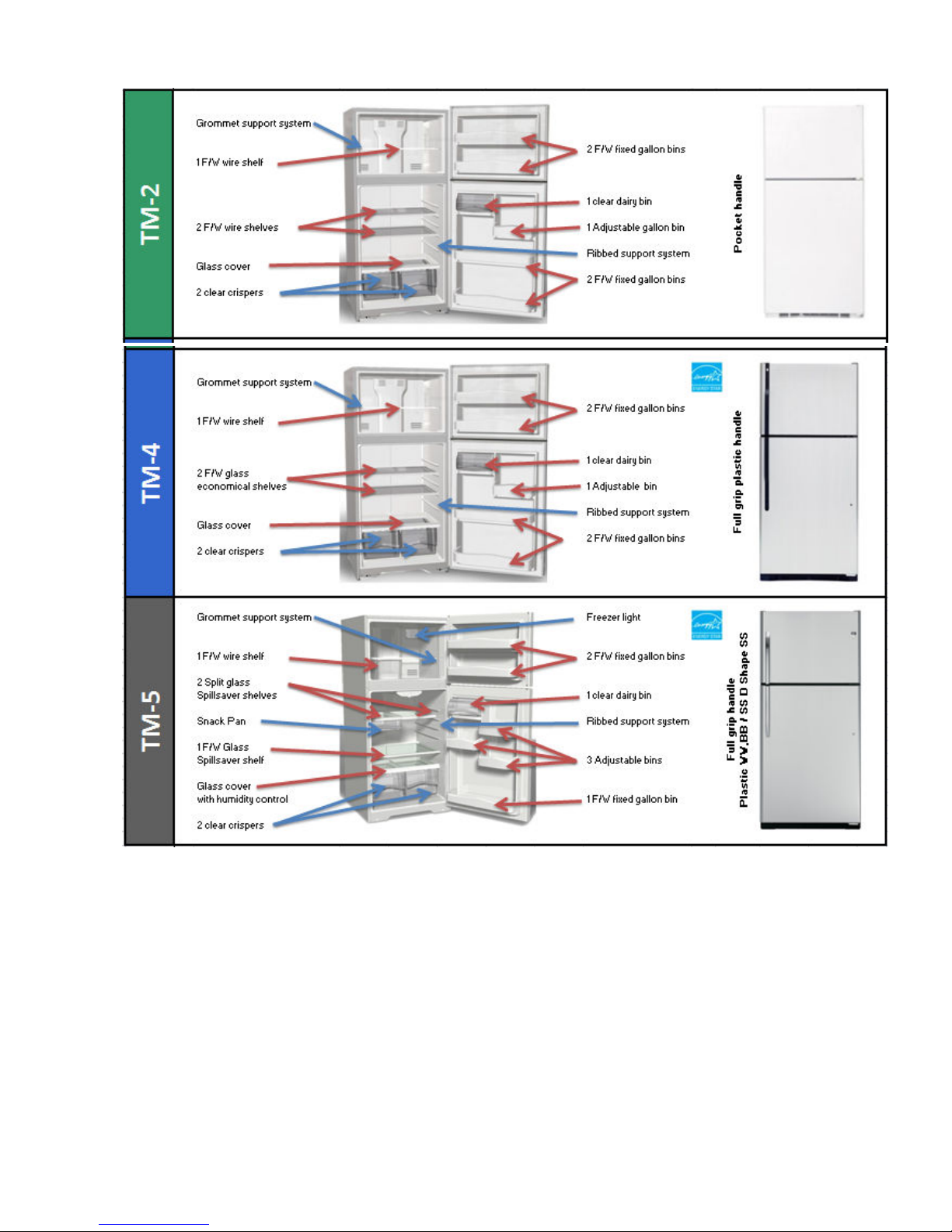
MODELS:
0 0 0
1 2 3 4 5 6 7 8 9 10 11 12 13 14 15 16 17
0 0 4000 0 0 0 1000 0 5200 800 6000 1300 200 1500
TM 2 T M 4 T M 5
WW WW BB WW BB LB BS WW BB LB BS WW BB SS WW BB SS
C
MTRC0FAZAR
C
C
GTRC0GAZAR
C
C
GTRC0HBZAR
C
C
GTRL0HBZAR
GTRS0HBZAR
C
C
GTRC0HBZAL
C
C
GTRL0HBZAL
GTRS0HBZAL
C
C
GTRC0KBZAR
C
GTRS0KBZAR
C C
C
GTRC0KBZAL
PRODUCT
General Information
Brand GE
Configuration Top Freezer
Total (cubic feet) 20.0
Controls
Type Knob, Electro-mechanical and Knob, electronic
Location Upfront
Features Temp (1-9)
Sensors No
Graphics GE
GE Smartwater
Filter No
Lighting 1-40W
Protective Lamp Covers Clear
Internal Dispenser No
Door Hinge Hinge Right. Reversible
Door Stops Yes
Leveling System 2 Point Front Adj.
Handles
Type GE Face Mounted Plastic
Color Color Matched
Reversible Yes (No kit required)
Defrost Type No Frost (Frost guard)
Air Clearances
Each Side (in.) 1/8
Top (in.) 1
Back (in.) 1
POWER
Electrical Requirements
Volts/Hertz/Amps 120V;60Hz;15A
GTRS0KBZAL
Page 11
– 9 –
Page 12

– 10
SERVICE REVIEW:
REMOVE DOORS:
TOP HINGE WITH 5/16"SOCKET SCREWDRIVER REMOVE TWO NUTS.
REMOVE THE TOP HINGE
Page 13

– 11
REMOVE THE FREEZER DOOR
INTERMEDIATE HINGE:
WITH TORX T-15 HEAD SCREWDRIVER REMOVE THREE SCREWS AND REMOVE
INTERMEDIATE HINGE
Page 14
– 12
REMOVE FRESH FOOD DOOR:
LOWER HINGE:
WITH 5/16"SOCKET SCREWDRIVER REMOVE TWO NUTS.
Page 15
– 13
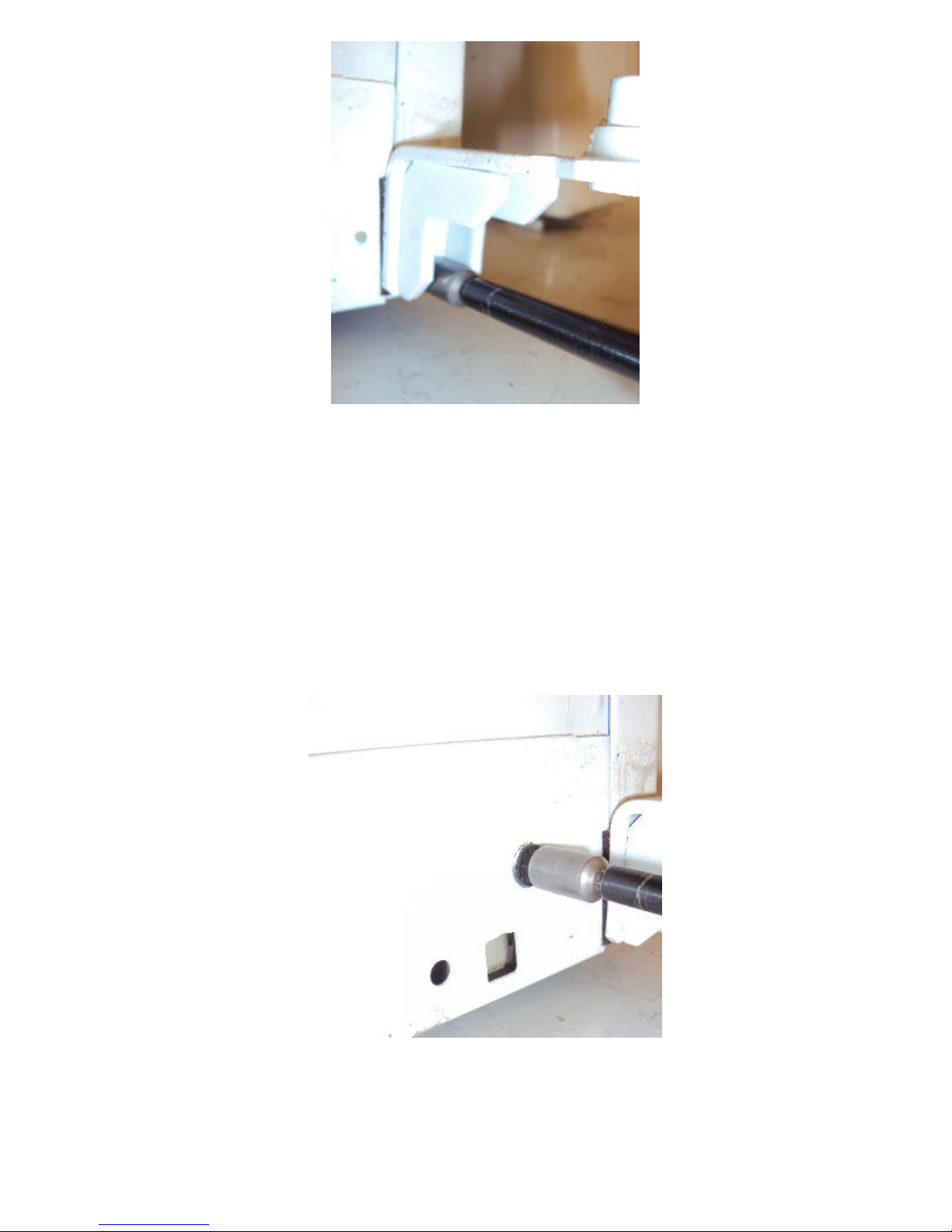
ROLLERS
ROLLERS AT THE BASE OF THE CABINET ENABLE THE CUSTOMER TO EASILY MOVE
THE REFRIGERATOR. CABINET LEVELING IS DONE BY ADJUSTING THE FRONT
ROLLERS. TO ADJUST THE FRONT ROLLERS, USE A 3/8-IN. SOCKET OR A LARGE FLAT
HEAD SCREWDRIVER TO TURN THE ROLLER ADJUSTMENT SCREWS LOCATED BEHIND
THE BASE GRILLE.
FREEZER COMPARTMENT
Page 16

– 14
LIFT UP THE LEFT SIDE OF THE SHELF AND SLIDE IT LEFT INTO THE CENTER OF THE
SHELF SUPPORTS.
ROTATE THE RIGHT SIDE OF THE SHELF UP AND OUT OF THE SHELF SUPPORTS
ICEMAKER
REMOVE THE ICEMAKER AND WITH THE PHILLIPS HEAD SCREWDRIVER TWO SCREWS
PRESS AND
PULL
COVER EVAPORATOR
Page 17

– 15
REMOVE THE COVER EVAP WITH THE PHILLIPS HEAD SCREWDRIVER FOUR SCREWS
EVAPORATOR FAN MOTOR
DISCONNECT TERMINALS AND CONNECTOR
Page 18

– 16
EVAPORATOR AND HEATER DEFROST
THE DEFROST HEATER IS A SINGLE-TUBE, RADIANT HEATER. IT IS HELD IN PLACE BY 2
TABS ON THE EVAPORATOR (1 ON EACH SIDE) AND BY 2 CERAMIC AND WIRE
SUPPORTS.
THE CERAMIC AND WIRE SUPPORTS PREVENT THE HEATER FROM SAGGING AND
TOUCHING THE METAL DRAIN PAN IF THE GLASS IS BROKEN.
HEATER
DEFROST
DEFROST DRAIN
PROBE
Page 19

– 17
CONTROL BOX
REMOVE THE CONTROL BOX WITH THE PHILLIPS HEAD SCREWDRIVER TWO SCREWS
COMPRESSOR:
DRYER
COMPRESSOR
NO-CLEAN
CONDENSER
CONDENSER FAN
Page 20

– 18
RATING PLATE
The rating plate, located inside the refrigerator
on the upper left-hand side, contains the model
and serial numbers. Additionally, the rating plate
specifies the minimum installation clearances,
electrical voltage, frequency, maximum
amperage rating, and refrigerant charge and
type.
MINI-MANUAL
The mini-manual, located behind the base grille,
is secured to the underside of the cabinet for
shipping with a piece of tape. After referencing
the mini-manual, return it to its original location
for future use.
DOOR REVERSAL
head WITH 5/16"SOCKET SCREWDRIVER are
used to mount the top, center, and bottom
hinges to the cabinet. Mounting holes in the
hinges are not elongated, and the hinges are
not adjustable. When reinstalling the hinges,
tighten screws firmly but avoid overtightening to
prevent stripping.
Note:
• When reversing the door swing, read all
instructions thoroughly before starting.
• When handling parts, use caution to avoid
scratching paint.
• Sort screws to correspond with related parts
and be certain to use the proper screw with
each part.
• Place doors on a protected surface to
prevent damage.
• Once the door reversal procedure has been
initiated, do not move the cabinet until the
procedure is complete.
• Unplug the refrigerator from its electrical outlet.
• Empty all door shelves, including the dairy
compartment.
Mini-Manual Located Under Base Grille
Rating Plate Location
Page 21

Freezer Door
1. Tape freezer door shut with masking tape.
Remove the hinge cover from the freezer
door hinge (some models).
2. Remove 2 (T-20) Torx head screws and the
top hinge.
3. Remove the tape and tilt the door away from
the cabinet. Lift the door off the center hinge
pin and place on a protected surface.
Fresh Food Door
1. Tape the fresh food door shut with masking
tape.
2. Remove the center hinge pin with a 3/4-in.
socket.
3. Remove the tape and tilt the door away from
the cabinet. Lift the door straight up and off
the bottom hinge and place on a protected
surface.
Note: If the washer is not on the bottom hinge,
check to see if it is stuck to the bottom of the
door.
Reversing the Doors
1. Install the top hinge and screws on the
opposite side of the cabinet. Do not tighten
the screws at this time.
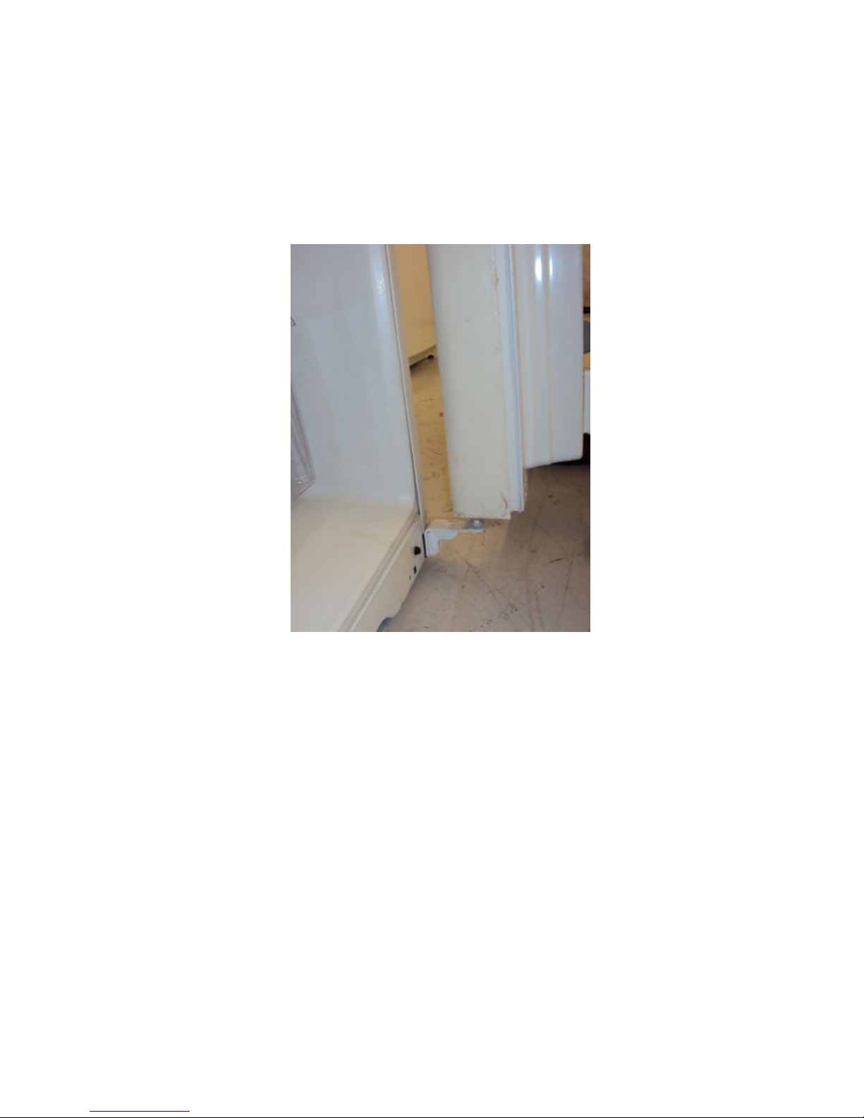
2. Remove the base grille by pulling it straight
out from the unit.
Note : If the washer is not on the bottom hinge,
check to see if it is stuck to the bottom of the
door.
3. Using a Torx driver, remove the screws and
bottom hinge from the cabinet and install on
the opposite side of the cabinet.
– 7 –
Top
Hinge
Hinge
Pin
Page 22

4. Cover the blade of a putty knife or small flat
screwdriver (to avoid scratching the paint)
and use the edge to gently pry the colormatched screw cap off the screw heads.
Note: Keep the screws with the center hinge.
These are longer screws and will be used when
installing the center hinge on the opposite side
of the cabinet.
5. Remove 3 Torx head screws and the center
hinge.
6. Remove the mullion cover using the putty
knife or screwdriver. Install the cover on the
opposite side of the cabinet.
7. Install the center hinge with the three long
screws on the opposite side of the cabinet.
Replace the color-matched cap.
8. Move the metal door stop and any associated
screws to the opposite side of the door.
Fresh Food Door Handles
1. Remove the plug button by carefully prying
underneath the edge with a small, flat blade.
Remove the screw that fastens the bottom of
the handle to the door. Remove the lower
part of the long handle (some models).
2. Remove the 2 screws and the handle from
the top of the door.
– 8 –
Long Handle
Short
Screw
Mullion
Cover
Handle
Hole
Pin
Plug
Screw
Cap
Short
Handle
Handle
Plug
Handle
Plug
Page 23

– 9 –
3. After the handle has been removed, move
the small plug buttons to the opposite side of
the door and install in the screw holes.
4. Move the large plug button to the opposite
side of the door and install in the thimble
hole.
5. Move the front door plug button to the
opposite side of the door and install in the
screw hole.
6. Install the handle to the opposite side of the
door with 3 screws.
Note: If equipped with long handle, ensure that
pin in the lower part of the handle is installed in
bottom of the door.
7. Install handle plug.
Plug Button
Long
Handle
Handle
Plug
Small
Plug
Buttons
Button
Short
Handle
Hole
Pin
Handle
Plug
Page 24

Freezer Door Handles
1. Remove the screws and handle from the
freezer door.
2. Move the plug button to the opposite side of
the door and install in the handle screw hole.
3. Install the handle to the opposite side of the
door using the holes closest to the edge of
the door.
Rehanging The Doors
1. Lower the fresh food door onto the bottom
hinge pin.
Note: Ensure that the washer is on bottom
hinge pin.
2. Line up the fresh food door with the center
hinge bracket. Install the hinge pin in the
center hinge bracket and door with a 3/4-in.
socket. Tighten the hinge pin in the center
hinge bracket.
3. Install the freezer door onto the center hinge
pin and upper hinge (screws loose). Support
the door on the handle side and make sure
the door is straight and the gap between the
doors is even across the front. While
holding the door straight, tighten the top
hinge screws.
– 10 –
Hinge
Pin
Center
Hinge
Bracket
Center Hinge
Pin
Page 25

– 11 –
SHELVES and BINS
Note: Not all features are on all models.
Some models have wire shelves that
can be
adjusted in the same manner.
Refrigerator
To
remove:
Tilt the shelf up at the
Lift the shelf up at the back
the shelf
To
replace:
While tilting the shelf up, insert
hook at the back of the shelf in a slot on
the
track.
Lower the front of the shelf
bottom
of the shelf locks
Freezer
To
To
Compartment
remove:
Lift up the left side of the shelf
it left into the
supports.
Rotate the right side of the shelf up and
out of the shelf
replace:
Holding
left end of the shelf into
shelf
supports
desired
level.
Insert the right end of the shelf
shelf
supports
each end of the shelf on
the shelf
Spillproof
Spillproof
help
shelves. To
see
Rearranging
Shelves
shelves have special edges
prevent
spills from
remove
Compartment
front.
out.
center
of
supports.
the shelf
supports.
diagonally,
on
the
at the same
(on some models)
dripping to lower
or
replace
the Shelves
side wall at the
.
and bring
until
into place.
and
the shelf
insert
the center
into
level.
Rest
the bottom
the shelves,
the
the
to
top
slide
the
of the
the
of
NOTE:
For models with
icemaker, the freezer shelf must
an automatic
be
in
lower position for the ice cube bucket
the
cubes.
the
to
catch
Page 26

– 12 –
Slide-Out Spillproof
The
slide-out spillproof
reach items stored
special edges
spills
from dripping
To remove:
are designed
Remove all items from
Slide the shelf out until it
Lift the front edge of the shelf
central
tabs are above the
Continue pulling
it can be
removed.
Shelf
(on
shelf
allows you
behind others.
to help
to lower
shelves.
shelf.
stops.
front bar.
the shelf
forward
some
The
prevent
until
the
until
models)
to
To
replace:
Place the rear shelf tabs just in
the
central notches
Slide the shelf in until the
are slightly
behind
Lower the shelf into place until it is
horizontal
Make sure
and
doesn’t move freely
and slide the
that the
Make sure you push
in before you close
the
shelf
sits
from
the
shelves all
the door.
on the
front bar.
shelf in.
flat
after
side
front
shelf frame.
central
tabs
reinstallation
to side.
the
way
of
Finger hold
Snugger
Adjustable
Door
Adjustable
refrigerator
To remove:
To
replace or
molded supports
Bin will lock in
Bins on the
bins can easily be
to work
area.
Lift bin
straight
relocate:
Engage the bin in the
of the
door,
place.
carried
up, then
and
from
pull out.
push in.
The snugger
or sliding of small items
shelf. Grip the finger
the
snugger
helps
and
prevent
hold
move it
tipping,
spilling
stored
on the
near the rear of
to fit your
needs.
door
Non-Adjustable
To remove:
pull
To replace:
supports
lock in
Lift the shelf
out.
Engage the shelf in
on the door and
place.
Shelves on the Door
straight up
push
then
the molded
down. It will
Freezer Tilt Out Bin
Push the
To remove:
it
To replace:
the
down. It will lock in
NOTE:
button
Hold the sides of the bin
straight
up, then pull
Engage the ends of the bin in
molded supports
Do not
overload
(on
some models)
as you tilt out the
out.
on the door
place.
the bin.
bin.
and
lift
and push
Page 27

– 13 –
of
To
remove,
position,
position and
slide
lift
the
lift it
the
rack
out to the
rack
up and past the
out.
stop
stop
Shelf Saver Rack
Slide-out beverage rack
soda or
two
wine/water bottles (lengthwise).
(on some
holds
models)
twelve
cans
It can be removed for cleaning.
Fruit and Vegetable Crisper
Excess water that may
bottom
should
of the
be wiped
drawers
dry.
accumulate
or
under the drawers
in
the
Adjustable Humidity Crisper
Slide the
HIGH
recommended
control
setting
all the way to
to
provide
for
most vegetables.
high humidity
(on some models)
the
Slide the
setting
recommended for
control
to
provide
all the way to
lower humidity
most
fruits.
the
LOW
levels
Snack Pan
This pan can be
location
(on some models)
moved
for your
family’s needs.
to the
most useful
Adjustable Temperature
When the pan is
the left side and the lever is set at
air from the
to keep it very
You can move the pan to any
don’t
want the extra cold
placed
freezer
cold.
is
Deli
in the top 6
COLDEST,
forced around
location if you
storage.
Pan
slots
the pan
on
To remove,
position,
position
(on some models)
The
between
When set at
normal refrigerator temperature.
The
storage
slide the pan out to the
lift the pan up and past
and lift it
settings
coldest setting provides
cold
area.
can be
cold,
stop
the
stop
out.
adjusted anywhere
and coldest
the pan will stay at the
the coldest
.
Page 28

– 14 –
Crisper
To Remove:
These drawers can be
lifting up slightly while
past the
Removal
stop
location.
removed
pulling
easily
by
the drawer
When
the
door
cannot be
remove
first. Make sure the drawer
door is fully
front of the
the latch and slide
which the drawer is
door. Remove
the drawer
closed. There
center
the
farthest
slide
rail.
the center
attached,
drawer.
fully
opened,
from
the door
closest
to the
is a latch at the
Push down on
slide rail, to
away from the
Page 29

– 15 –
CABINET CONSTRUCTION
Cabinet
The outer case is made of prepainted steel with
a textured finish. The fresh food and freezer
liners are made of plastic with a smooth finish.
Individual compartments provide separation and
enhanced individual control between the
compartments. The plastic liner provides a
thermal break between the interior of the
refrigerator and freezer compartments and
reduces the transfer of heat from the room into
the fresh food and freezer compartments. The
liner is not removable or replaceable.
Base Grille
The base grille is attached to the cabinet with
two steel spring retainers that clip into elongated
openings in the base channel. To remove the
grille, pull it straight forward.
Doors
The doors are of one-piece construction with
foam insulation. One-piece construction
provides superior thermal performance and
reduces air infiltration. During manufacturing,
the doors are filled with hot foam insulation.
This may cause slight distortion or ripples in the
inner door liner. This is a normal condition and
is the result of the insulating process. This
process requires doors to be equipped with vent
holes that allow air to escape when the door is
filled with foam. A small amount of foam may be
visible around the vent holes.
The inner door panels and outer door panels
cannot be separated and must be replaced as
an assembly.
Vent Holes
GEA01138
GEA01144
GEA01 145
Page 30

– 16 –
Door Gaskets
The fresh food and freezer doors have magnetic
gaskets that create a positive seal to the front of
the steel cabinet. The magnetic door gaskets
are secured to the fresh food and freezer doors
by a barbed edge that locks into a retainer
channel.
1. Starting at any corner, pull the old gasket out
of the retainer channel.
2. Soak the new gasket in warm water to make
it pliable.
3. Push the barbed edge of the gasket into the
retainer channel.
Rollers
Rollers at the base of the cabinet enable the
customer to easily move the refrigerator.
Cabinet leveling is done by adjusting the front
rollers. To adjust the front rollers, use a 3/8-in.
socket or a large flat head screwdriver to turn
the roller adjustment screws located behind the
base grille. The rear rollers are not adjustable.
To remove a front roller assembly from the base
of the cabinet:
1. Tilt the cabinet back and place a
3-in. block under the side of the unit.
2. Remove 3 hex head 1/4-in. screws from the
roller assembly.
3. Loosen the adjustment screw until it
disengages from the assembly and remove
the assembly from the cabinet.
4. Remove the E-ring to remove the
adjustment screw from the base channel.
Note: When reinstalling the roller assembly,
position the nut with the flared thread toward the
rear of the unit.
GEA01150
GEA01147
Page 31

– 17 –
ICEMAKER
Water Valve
A single-coil, 120-VAC valve is secured to the
rear of the cabinet, inside the machine
compartment, on the left-hand side.
GEA01142
GEA01137
Page 32

– 18 –
AIRFLOW
Freezer Compartment
Cold air from the evaporator is forced up against
the top of the freezer and the back of the
evaporator cover. It is then discharged through
slots along the air tower at the rear of the
freezer compartment.
Air is circulated by the evaporator fan
throughout the freezer compartment, where it
picks up heat and moisture. The evaporator fan
then draws the warmer, moisture-laden air
through return louvers in the bottom of the
evaporator cover. The air is then drawn through
the evaporator where heat is removed and
moisture is deposited as frost.
Fresh Food Compartment
Some of the cold air that is being forced against
the top of the freezer and back of the evaporator
cover is diverted through the lower portion of the
freezer air tower and is pushed though the
mullion hole into the fresh food compartment air
channel. The air then exits the air channel in the
front of the fresh food compartment, creating a
curtain of cold air along the front of the shelves.
The fresh food air channel also has a rear
discharge to maintain deli drawer temperatures.
Air circulates throughout the fresh food
compartment, picking up heat and moisture.
The air is then returned to the evaporator
through the return air ducts located at the top
right and left of the fresh food compartment.
Note: These refrigerators do NOT use damper
assemblies to regulate the flow of air to the
fresh food compartment. Airflow is regulated by
a three-speed evaporator fan and a sized air
duct system that provide predictable, consistent
air exchange rates for each level of fan speed.
AIR FLOW
Airflow
COLD AIR
MIXED AIR WARMER AIR
GEA01143
Page 33

– 19 –
Evaporator Fan
The position of the fan blade in relation to the
shroud is critical. Refer to graphic for
specifications.
If the fan shorts, it will damage the main control
board. If the resistor on the main control board
is burnt, you must replace the fan and the board
(see photo).
Evaporator Fan Adjustment
5/16" ±
0.03
1.0" ± 0.05 Target
Blade tip
Motor
GEA01149
Orifice
Air Flow
Airflow
Page 34

– 20 –
EXPLODED VIEWS
Knob, Electro-mechanical
EX
PL
OD
ED
VIE
WS
Page 35

– 21 –
Knob, Electronic
Page 36

– 22 –
structure
Page 37

– 23 –
FREEZER DOOR
FRESHFOOD DOOR
Page 38

– 24 –
HINGE:
Page 39

– 25 –
RACKS SPILLPROOF
Page 40

– 26 –
Condenser Fan
The condenser fan utilizes a DC motor that
operates on a single speed and is mounted in
the machine compartment with the No-Clean
condenser. The fan and fan shroud are
mounted on one end of the condenser, the other
end of the condenser is blocked. When the fan
is operating, air is pulled from the center of the
condenser, drawing air in through the coils. The
air is then exhausted over the compressor and
out the right side of the refrigerator.
Inlet air is available through the left front and left
rear of the machine compartment. A rubber
divider strip underneath the refrigerator divides
the inlet and outlet sides of the machine
compartment.
The rear access cover must be tightly fitted to
prevent air from being exhausted directly out of
the rear of the machine compartment, bypassing
the compressor.
The condenser fan is mounted with screws to a
fan shroud and mounting bracket that is
attached to the condenser. To remove the fan:
1. Remove the rear access cover.
Rear
Condenser Fan Adjustment
2
.
R
Front
Baffle
GEA01152
emove 1 screw
from the
Page 41

– 27 –
condenser fan mounting bracket.
3. Remove 2 screws from the condenser fan
cover.
4. Pull the fan out and disconnect the electrical
connector.
1/2"
Fan
0.375"
Airflow
Air Flow
0.50" ±
0.05
Housing
Motor
Bracket
GEA01 148
Page 42

– 28 –
E
E
DEFROST SYSTEM
Adaptive Defrost
Adaptive Defrost can be described as a defrost
system that adapts to a refrigerator’s
surrounding environment and household usage.
Unlike conventional defrost systems that use
electromechanical timers with a fixed defrost
cycle time, Adaptive Defrost utilizes an
intelligent, electronic control to determine when
the defrost cycle is necessary. In order to
accomplish the correct defrost cycle time, the
main control board monitors the following
refrigerator operations:
• Length of time the refrigerator doors were
open since the last defrost cycle
• Length of time the compressor has run
since the last defrost cycle
• Amount of time the defrost heaters were on
in the last defrost cycle
Adaptive Defrost is divided into 5 separate
cycles. Those operations are:
• Cooling Operation
• Pre-Chill Operation
• Defrost Heater Operation
• Dwell Period
• Post Dwell
Adaptive Defrost (Cooling Operation)
During the cooling operation, the main control
board monitors door opening (fresh food and
freezer doors) and compressor run times. The
board counts the time the doors are open. It
reduces the length between defrosts by 210
seconds (multiplication factor) for each second
that each door is open (if both doors are open,
it reduces it by twice the amount). The
multiplication factor reduces compressor run
time. If the doors are not opened, the
compressor will run up to 60 hours between
When the main control board determines that
defrost is necessary, it will force the
refrigerator into a continuous cool mode (pre-
defrosts. If the doors are opened frequently
and/or for long periods of time, the compressor
run time between defrosts will be reduced to as
little as 8 hours.
Adaptive Defrost (Pre-chill Operation)
F
C˚
R
E
-4˚
E
Z
-7˚
R
15˚ /
A
I
12˚
R
T
-15˚
E
-18˚
M
P
21˚
A
-10˚ / -
R
23˚
T
U
-15˚ / -
26˚
R
E
S
29˚
F˚ /
25˚ /
20˚ /
-9˚
10˚ / -
5˚ /
0˚ /
-5˚ / -
-20˚ / -
PRE-CHILL MODE
08:00
09:00 10:0 0 11:00
12:00
13:00
14:00 15:00 16:00 17:00 18:00
Pre-Chill Defrost
chill). During pre-chill, the freezer temperature
may be driven below the set point. However,
the fresh food temperature will be regulated by
the evaporator fan running at low speed. Prechill will last for 2 hours. These models do not
have a defrost holdoff.
Adaptive Defrost (Defrost Heater
Operation)
After 2 hours of pre-chill operation, the main
control board turns off the compressor,
condenser fan, and evaporator fan.
During defrost operation, the main control board
monitors the evaporator temperature using
evaporator thermistor inputs. Typically, the
evaporator thermistor will sense a temperature
of 65°F within 25 minutes. When the thermistor
senses 65°F, the main control board will
terminate defrost heater operation. Maximum
defrost cycle (heater on) time is 45 minutes
(main control board time out).
The defrost system is protected by a defrost
termination thermostat (switch). The thermostat
opens when the evaporator temperature raises
to 140°F and closes when the evaporator
temperature lowers to 110°F.
Page 43

– 29 –
Adaptive Defrost (Dwell Period)
After defrost heater operation has been
terminated by the main control board, a 5minute dwell period occurs. During this period,
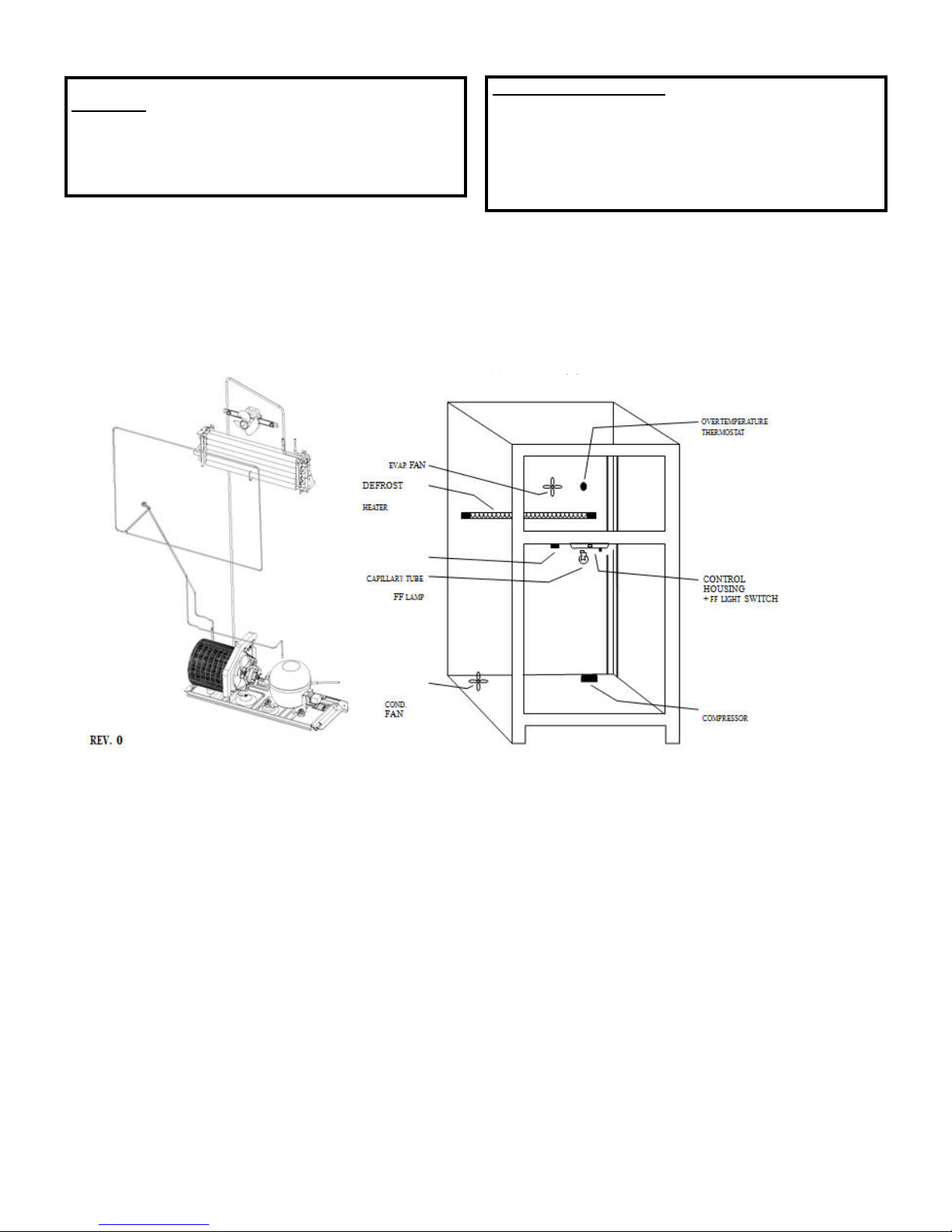
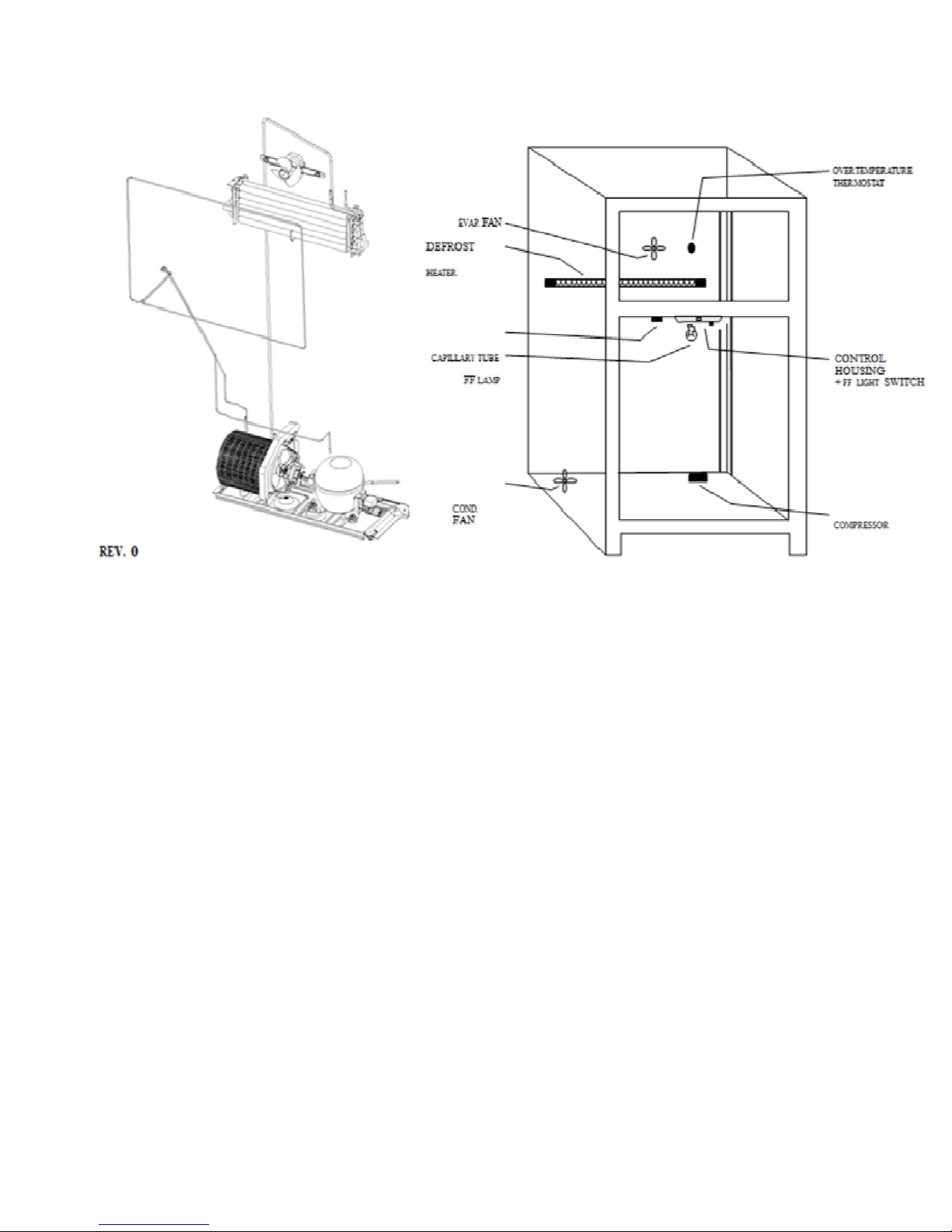
the compressor, condenser fan, and the
evaporator fan remain off. The remaining frost
melting from the evaporator will continue to drip
and drain so that prior to the cooling operation,
the evaporator will be totally clear of any
moisture. After the 5-minute dwell period, the
unit goes into post dwell.
Adaptive Defrost (Post Dwell)
The post dwell period is designed to cool the
evaporator before circulating air within the
refrigerator. This prevents any residual heat on
the evaporator from being distributed in the
freezer. During this period, the compressor is on
and the condenser fan is on, but the evaporator
fan is off. Post dwell will last 15 minutes or until
the evaporator temperature reaches 30°F on
these models.
Normal Operating Characteristics That
Are Different from Previous Models
• Evaporator fan running without compressor
or condenser fan.
• Post Dwell (Adaptive Defrost), compressor,
and condenser fan on with evaporator fan off
after defrost cycle.
• Liner Protection Mode, fan comes on when
the doors are open for 3 minutes.
• Evaporator fan and compressor can run
continuously for 2 hours (Adaptive Defrost).
• Different sound levels can be heard when
the fan changes speed.
• Response time for drastic temperature
change is 2 to 10 minutes. The main control
board will only respond to 8 degrees
(Fahrenheit) of temperature change per
minute as determined by resistance of
sensor.
Abnormal Operating Characteristics
(Incorrect Operation)
• Rapid fan speed changes, fan takes at least
1 minute to change speeds.
• Compressor running without the condenser
fan. The compressor and condenser fan
should always run at the same time.
Liner Protection Mode
The liner protection mode will activate if either of
the doors have been open for 3 minutes. This
mode will start the evaporator fan on high
speed.
This mode is controlled by 2 timers. Timer 1
monitors door-open time. A 3-minute door-open
count begins when the door is opened. If 3
minutes elapse before the door is closed, the
liner protection mode will become active. Once
the door is closed, timer 1 resets and liner
protection mode goes into standby. In standby,
normal fan and damper operations resume and
timer 2 begins a 3-minute door-closed count. If
3 minutes elapse without a door opening, liner
protection mode will completely deactivate. If a
door is opened within the timer 2 door-closed
count, the remaining time in the door-closed
count will be deducted from the timer 1 dooropen count.
Page 44

– 30 –
Defrost Heater
The defrost heater is a single-tube, radiant
heater. It is held in place by 2 tabs on the
evaporator (1 on each side) and by 2 ceramic
and wire supports.
The ceramic and wire supports prevent the
heater from sagging and touching the metal
drain pan if the glass is broken.
Evaporator Thermistor
The evaporator thermistor is mounted on the
upper right side of the evaporator. The defrost
cycle will terminate when the main control board
detects 65°F from the evaporator thermistor.
The main control board must sense 65°F in less
than 45 minutes, or the defrost cycle will time
out. Normal defrost time is 25 minutes or less,
not including the 5-minute dwell or post dwell
periods.
Defrost Overtemperature Thermostat
The defrost overtemperature thermostat
(bimetal switch) is mounted on the evaporator
and provides overtemperature protection during
defrost. This thermostat will open at 140°F and
will close at 110°F.
Note: The main control board will not know if
the heater does not come on due to a broken
heater, open defrost overtemperature
thermostat, or an open wiring harness. The
defrost heater is controlled by maximum time on
the main control board or temperature at the
evaporator thermistor.
Heater Supports
Defrost Drain Probe
Defrost Heater Supports
Defrost Overtemperature Thermostat
Evaporator Thermistor
Page 45

– 31 –
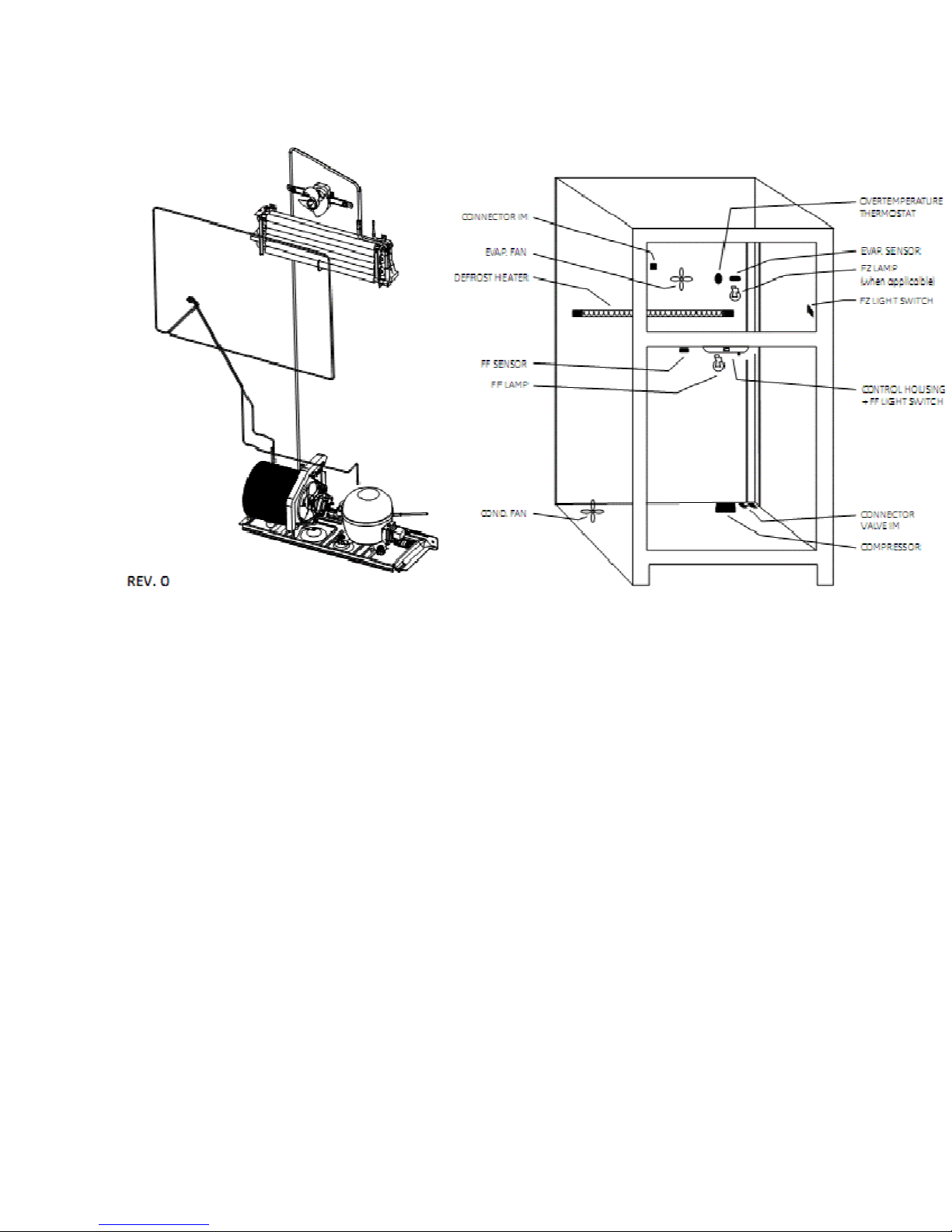
Defrost Probes (on some models)
A defrost drain probe is attached to the
evaporator and extends into the drain opening.
This probe transfers heat to the drain opening
during defrost.
Two additional defrost probes are attached to
the sides of the evaporator. These probes
extend upward between the freezer wall and
evaporator sides to assist the defrosting
process.
Defrost Drain Probe
Evaporator
Page 46

– 32 –
CONTROL SYSTEM
Control Console
The control console, located at the top front of
the fresh food compartment, contains an
encoder (knob version) or a touch panel.
Remove the control console by removing 4 (1/4in.) hex head screws. Use care when
disconnecting the wire connectors from the
encoder or touch panel.
Temperature Encoder
The temperature encoder (knob version)
receives switched DC voltage from the main
control board. There are two possible failure
modes - both are open circuits.
An open circuit from the supply side results in
the refrigerator defaulting to midpoint. The
supply side consists of pins 1 and 2.
An open circuit from the return side results in
inconsistent run mode. The return side consists
of pins 3 and 6.
Failure of the fresh-food-only side results in the
fresh food defaulting to midpoint.
Failure of the freezer side results in the freezer
defaulting to midpoint.
Temperature Touch Panel
The temperature touch panel receives switched
DC voltage from the main control board.
Failure of input results in default to most recent
setting. Input consists of pins 2 to 3.
Failure of output results in erratic control.
Output consists of pin 1.
ADJUST
5
FREE ZER
TEMP
9 IS CO LDE ST
ADJUST RE FRIG ER ATOR
5
TEMP
ADJ UST
RE FRIG ER ATOR TEMP
9 IS
COLDEST
COLDER WA
RME R
ADJ UST
RE FRIG ER ATOR TEMP
9 IS
COLDEST
COLDER WA
RME R
COLDER
COLDER
ADJ UST
WAR MER
ADJ UST
WAR MER
FREE ZER
FREE ZER
9 IS
COLDEST
9 IS
COLDEST
TEMP
TEMP
ACT IVATE LOCK
HOL D
3
SEC S
ACT IVATE LOCK
HOL D
3
SEC S
Page 47

– 33 –
Control Board
127v
Vcc GND
In position 9,
The electronics architecture for top mount 20 ft model consists of 1 electronic board. The control
board reads analog signal from thermistors and convert it to temperature and controls the Compresor
and Defrost heater for Refrigerator operation. It also has 2 door signals to create adaptive defrost. It
communicates to the display board by serial port.
a) Feeding 127VAC control card in the main connector.
b) Measure voltage at the output of voltage regulator on the control card:
The value should be 5 + / - 0.2 VDC at the output of regulator U3 (TP TP Vcc and GND).
Temperature Verification and start cutting
a) Feeding 127VAC control card in the main connector
b) Turn the potentiometer knob in position 5 (counterclockwise to clockwise).
the flat side of
the stem is at
Page 48

– 34 –
c) placing the temperature sensor in the cold well.
ON
OFF
3
7.02 1.39
1.17 -
1.59
Vcc
P1
d) Measure the temperature and start cutting in this position.
- The card must be cut and start the compressor relay after the temperatures of the table.
Temp
7.02 1.39
1
7.02 1.39
2
4
1.69 -1.67
1.69 -1.67
5
1.69 -1.67
6
7
0.44 -2.33
8
-0.28 -3.06
9
Temp
e) Remove the power supply to the card.
Note: In position 0 must remain off the compressor and defrost relays
Check defrost relay (CTQ).
a) Feeding 127VAC control card in the main connector.
b) Wait for the compressor relay is activated.
c) Force the melting by a short circuit between pins VCC and P1
d) The compressor will stop relay and defrost relay will be activated.
e) Remove the power supply to the card.
Page 49

– 35 –
Thermistors
This main control board uses input from 3 thermistors. These thermistors are located in the fresh
food section, the freezer section, and on the evaporator. The main control board monitors the
thermistors to determine the temperature in these areas of the unit and determines which
components to run and when to run them, based on this information.
Thermistor Values
Control
Setting
Fresh Food
Compartment
Temperature
Degrees
(C)
-40
-30
-20
-10
0
10
20
30
40
50
60
Compartment
Temperature
Temperature Set Point
Degrees
Freezer
-40
-22
104
122
140
(F)
-4
14
32
50
68
86
Fresh Food
Thermistor
Temperature Range
Resistance
in Kilo-ohms
166.8 kΩ
88 kΩ
48.4 kΩ
27.6 kΩ
16.3 kΩ
10 kΩ
6.2 kΩ
4 kΩ
2.6 kΩ
1.8 kΩ
1.2 kΩ
Chart
Freezer Thermistor
Temperature Range
0
1
2
3
4
5
6
7
8
9
Off
44°F
40°F
39°F
38°F
37°F
36°F
35°F
35°F
34°F
Minimum Maximum Minimum Maximum
Off
6°F
4°F
3°F
1°F
0°F
-1°F
-3°F
-4°F
-6°F
43°F
39°F
38°F
37°F
36°F
35°F
34°F
34°F
33°F
45°F
41°F
40°F
39°F
38°F
37°F
36°F
36°F
35°F
1°F
-1°F
-2°F
-4°F
-5°F
-6°F
-8°F
-9°F
-11°F
11°F
9°F
8°F
6°F
5°F
4°F
2°F
1°F
-1°F
Page 50

– 36 –
ELECTRICAL SYSTEM
Door Switches
The door switch (fresh food or freezer) closes when the door is open. When the door switch is
closed, L1 is provided to the compartment light(s). The main control board receives L1 input on
pin 6, J7 when the fresh food door switch is closed (door open). The main control board receives
L1 input on pin 4, J7 when the freezer door switch is closed (door open).
Schematic Knob, Electronic
Page 51

– 37 –
Schematic Knob, Electro-mechanical
Page 52

– 38 –
REFRIGERATION SYSTEM
The major components of the refrigeration
system are a reciprocating-type compressor,
condenser, condenser loop, dryer, and a spinefin evaporator. These components, except for
the condenser loop, are all replaceable
separately.
Compressor
The compressor is a reciprocating type. Refer
to the mini-manual for the BTU/hour rating and
the compressor capacity test specification.
A 1/4-in. O.D. copper process tube is provided
for access to the low-pressure side of the
refrigeration system.
The channel that the compressor is mounted in
must be disengaged from the cabinet to remove
the compressor.
Note:
Capillary tube must be clipped to
compressor suction line near the dryer. If
capillary tube is not clipped to suction line, a
knocking noise may occur during compressor
operation.
Refer to the compressor replacement
instructions included with the replacement
compressor.
No-Clean Condenser
The Condenser is a
condenser made of 3/16-in. O.D. steel tubing.
The outlet of the condenser is connected to a
copper jumper tube that is connected to the inlet
of the condenser loop. The No-Clean
condenser is accessed from the rear of the
cabinet and is designed to be more tolerant of
lint buildup than previous condensers. The
consumer, in normal operating conditions, will
never have to clean the condenser. If
necessary, only an ordinary appliance brush is
used. Air is drawn in from the outside diameter
of the condenser. A condenser fan baffle is
located at the rear to direct airflow through the
condenser. Functionally, the condenser does
the same job as previous models. Air is drawn
into the condenser from the front left and rear
left of the cabinet. Air exits only from the right
side of the cabinet.
No-Clean,
“jelly roll” style
Condenser Loop
The condenser loop, made of 5/32-in. O.D.
copper tubing, is foamed in place behind the
breaker frame and across the mullion. It is not
accessible for replacement. The tubing is
routed from the rear of the machine
compartment forward to the mullion, across the
mullion, across the right side of the freezer
compartment, across the top of the freezer
compartment, down the right side of the freezer,
and back to the rear of the machine
compartment. The outlet of the condenser loop
is connected to the dryer inlet.
Dryer
The dryer is positioned vertically in the center of
the machine compartment. A 1/4-in. O.D.
copper process tube, connected to the inlet of
the dryer, provides access to the high-pressure
side of the refrigeration system. The capillary is
connected to the outlet of the dryer.
Replacement of filter dryer requires additional
refrigerant when installed (0.5 oz).
Note:
The dryer is wrapped in mastic as a
sound reducer and foam tape for shipping
purposes. When replacing the dryer, the mastic
must be reinstalled to reduce sound. It is not
necessary to reinstall the foam tape.
Evaporator
The spine-fin evaporator, made of aluminum
tubing and formed into hairpin spirals, is located
below the evaporator fan housing at the back of
the freezer compartment. The replacement
evaporator is furnished without a heat
exchange.
Evaporator (Soldering Method)
1. Recover the refrigerant.
2. Remove the evaporator cover.
3. Remove the defrost thermostat.
4. Remove the defrost heater.
5. Disconnect the ground wire from the
evaporator and position all wiring to allow for
evaporator removal.
Page 53

– 39 –
6. Remove the 2 screws that hold the
evaporator to the cabinet.
Caution:
• If desoldering the evaporator, heat shield,
, must be used to
prevent damage to freezer liner.
• Protect wiring from heat during
desoldering and resoldering.
• To prevent damage to the capillary tube,
the capillary tube must be desoldered
first.
7. Desolder the capillary tube from the
evaporator.
8. Desolder the suction line. Use a pair of pliers
to hold the evaporator.
9. Remove the evaporator.
10. Using a file, score the capillary tube just above
the old solder and break the solder-covered
section off. This will help prevent the capillary
tube from becoming plugged when
resoldering.
11. Position the new evaporator in the cabinet.
Insert the suction line and capillary tube into
the evaporator.
12. Solder the suction line to the evaporator
using silfos.
13. Solder the capillary tube to the evaporator
using silfos.
Note:
Heat probe assists in defrosting drain.
During assembly, probe must be installed on
evaporator and in drain to prevent drain from
freezing closed.
14. Install a replacement dryer.
15. Evacuate and recharge the system using
currently accepted procedures.
Evaporator (LOKRING Method)
1. Recover the refrigerant.
2. Remove the evaporator cover.
3. Remove the defrost thermostat.
4. Remove the defrost heater.
5. Disconnect the ground wire from the
evaporator and position all wiring to allow for
evaporator removal.
6. Remove the 2 screws that hold the
evaporator to the cabinet.
Caution:
Tubing must be clean and free from
burrs when using LOKRING.
.
7. Replace the evaporator using the LOKRING
method .
• Cut the copper lines of the old evaporator
as close as possible to the aluminum
evaporator tubes.
• Cut the copper lines of the new evaporator
1-1/8 in. from the edge of the aluminum
evaporator tubes.
• Defrost thermostat can be moved from the
horizontal part of the copper line to the
vertical part, just above the bend.
Note:
Heat probe assists in defrosting drain.
During assembly, probe must be installed on
evaporator and in drain to prevent drain from
freezing closed.
8. Install a replacement dryer.
9. Evacuate and recharge the system using
currently accepted procedures.
Refrigerant Charge
The refrigerant used in this model is type
R134a. Refer to the mini-manual or model tag
for the exact refrigerant charge quantity.
Page 54

– 40 –
COMPONENT AND CONNECTOR LOCATOR VIEWS
Page 55

– 41 –
Relay and
Overload
(Under Cover)
Capacitor
Compressor
Dryer
No-Clean Condenser
Condenser Fan
Page 56

– 42 –
Basic refrigeration checks:
Door gasket seal OK?
Door switch - light turning off with NO
Reset electronics by unplugging
refrigerator for 15 seconds then
Is the evaporator fan running? NO
Is the condenser fan running?
Is the airflow in the fresh food
Is the resistance within range?
door closed?
plug back in.
Is the compressor running?
compartment normal?
Verify thermistors are within
proper range. NO
Check sealed system.
Does sealed system check
All OK?
YES
YES
YES
YES
YES
YES
OK?
Fresh Food Warm - Freezer Warm
Repair as
necessary.
Go to Evaporator
Fan Not Running
flowchart.
NO
NO
NO
Go to Condenser Fan
Not Running flowchart.
Go to Compressor Not Running
Look for blockage
at vents or heavy
frost on evaporator
Check wiring
connections. If OK,
replace thermistor.
cover.
flowchart.
Heavy frost
Blockage
Remove blockage from
evaporator cover vent
area.
Go to Heavy Frost
on Evaporator
Cover flowchart.
YES
Unit tests OK.
Run checks again. Look
for usage problem.
Page 57

– 43 –
Check control settings
Food at a setting of 5 and 5 with no door
openings for 12 hours should be:
Fresh food 36 F to 38 F
Freezer -5 F to +5 F
and
temperatures.
Control settings OK?
Basic refrigeration checks:
Door gasket seal OK?
Door switch - light turning off with NO
YES
door closed?
All OK?
YES
Reset electronics
unplugging refrigerator for 15
seconds then plug back in.
by
Is the evaporator fan running? NO
YES
Is the condenser fan running?
Is the airflow in the fresh food
Verify thermistors are within
Is the resistance within range?
YES
compartment
proper range. NO
YES
normal?
YES
Check
sealed
Does sealed system
Unit test OK.
Run checks again. Look for usage
system.
OK?
YES
problem.
check
NO
Freezer Warm - Fresh Food Normal
Adjust settings and allow
NO
24 hours to stabilize.
Repair as
necessary.
Go to Evaporator
Fan Not
Go to Condenser Fan
NO Not Running
NO
connections. If OK,
replace
Running
flowchart.
flowchart.
Check
wiring
thermistor.
Repair sealed
system.
Look for
at vents or heavy
frost on evaporator
blockage
cover
.
Frost
Blockage
Remove
evaporator
Go to
on
Evaporator
Cover
blockage
cover vent
area.
Heavy
Frost
flowchart.
from
Page 58

– 44 –
Fresh Food Warm - Freezer Normal
Check control settings
Food at a setting of 5 and 5 with no door
openings for 12 hours should be:
Fresh food 36 F to 38 F
Freezer -5 F to +5 F
and
temperatures.
Control settings OK?
YES
Basic refrigeration checks:
Door gasket seal OK?
Door switch - light turning off with NO
door closed?
All OK?
YES
Reset electronics by unplugging
refrigerator for 15 seconds then
plug
back in.
Is the evaporator fan running at
correct speed?
YES
Is the airflow in the fresh food
compartment normal?
Verify thermistors
Is the resistance within range?
Check sealed system.
Does sealed system check
YES
are
proper range. NO
YES
OK?
YES
within
Unit test OK.
Run checks again.
usage problem.
Look
for
NO
NO
NO
connections. If OK,
replace thermistor.
NO
Adjust settings and allow
24 hours to stabilize.
Go to Evaporator
Check wiring
Repair sealed
system.
Fan Not
Look for
at vents or heavy
frost on evaporator
Repair as
necessary.
Running
flowchart.
blockage
cover
.
Frost
Blockage
Remove blockage from
evaporator cover vent area.
Go to
Heavy
on
Cover
Frost
Evaporator
flowchart.
Page 59

– 45 –
Fresh Food Too Cold - Freezer Normal
no
YES
Check control
temperatures.
Food at a setting of 5 and 5
door openings for 12
Fresh food 36 F to 38
Freezer -5 F to + 5 F.
Do settings
settings and
with
hours
should
be:
F
require adjustment?
NO
Adjust
allow 24
stabilize.
settings and
hours
to
Advise consumer
refrigeration
requirements.
installation
of
Low
ambient
temperature? Is the
room
temperature above
55
F?
NO
thermistor is
Is
operating at proper
Run checks again.
by
unplugging
seconds.
YES
Verify fresh
proper
resistance within
range?
Is evaporator
speed?
Unit tests
Look for
food
within
range.
YES
YES
OK.
Reset
refrigerator for 15
usage
fan
electronics
problem.
NO
NO
Check
connections.
wiring is
thermistor.
Go to
Evaporator
Fan Not
flowchart.
OK, replace
wiring
If
Running
Page 60

– 46 –
Unplug
Warm freezer thermistor to 70 F.
Connect power and
temperature controls to 5
Does compressor
Check for 120 VAC.
Is 120
thermistor is within
refrigerator.
NO
VAC present?
YES
Verify
freezer
proper
Is
within
Replace main
range.
the resistance
range?
YES
board.
Compressor Not Running
set
and
5.
start?
YES
YES
Adjust
settings and
allow 24 hours to
stabilize.
Direct
test
compressor.
Did compressor
start?
YES
NO
Check wiring to compressor,
Replace
Replace
compressor.
overload,
defective part.
and
relay.
Check wiring
NO connections. If
replace thermistor.
OK,
Page 61

– 47 –
Are interior lights on?
YES
Does unit have
encoder or touch
panel?
Encoder
Is voltage present?
Short in fan motor circuit.
YES
Go to fan flowchart.
Refrigerator Not Responding
NO supply voltage. NO
Check house
120 VAC present?
YES
Check for 120 VAC
120 VAC present?
YES
Repair wiring
connections at 6-pin
connector.
Touch Panel
Unplug (temperature
control).
Does refrigerator
start?
YES
Replace encoder
board.
NO proper range.
House wiring
Repair or replace
Is touch panel lit?
be set to 5 and 5?
thermistor is within
problem.
power cord.
YES
Can touch panel
YES
Verify freezer
Is the resistance
within range?
YES
Replace main
control board.
Check for 12 VDC at
NO voltage, check wiring.
NO
NO
J4-2 to 3. If no
If wiring OK, replace
touch panel.
Membrane, touch
panel, or wiring.
Check wiring
connections. If
wiring is OK, replace
thermistor.
Page 62

– 48 –
Note:
Evaporator Fan Not Running
• When no voltage at main control board, make certain to check for shorted fan motor (less
than 1k ohm between). A shorted fan motor will damage the replacement main board.
Check fan for obstruction.
Find obstruction?
NO
Open door and leave open
for 3 minutes to initiate liner
protection mode.
Does fan begin running?
Unplug refrigerator to reset
Reconnect power. Warm
freezer thermistor to 70 F
and set temperature controls
Did evaporator fan start?
NO
main control board.
to 5 and 5.
YES
YES
YES
Remove
obstruction.
Check thermistors
using thermistor
values or self-
diagnostic test 0-7.
Thermistors pass
Test?
NO
Adjust settings and allow
24 hours to stabilize.
YES
Replace main
Check wiring
connections. If OK,
replace thermistor.
board.
At the fan connector, check 8
NO
to 13 VDC
NO
Check for 13 VDC
NO
Replace main
control board.
YES
YES
Replace
evaporator fan
motor.
Repair wiring between
main control board and
evaporator fan motor.
Page 63

– 49 –
Note:
Condenser Fan Not Running
• Compressor and condensor fan should always operate at the same time.
• When no voltage at main control board,
Check fan for obstruction.
Unplug the refrigerator to
reset main control board.
Warm freezer thermistor
to 70 F. Reconnect
power and set
temperature controls to 5
and 5. Recheck voltage.
Is voltage correct?
Adjust settings and allow
YES
24 hours to stabilize.
NO
At the condenser
fan connector,
check for 13 VDC
.
Is voltage correct
for both?
YES
Replace condenser
fan motor.
NO
.
Check for 13 VDC
Is voltage correct for
both?
YES
Repair wiring between
main control board and
condenser fan motor.
NO
Replace main
control board.
 Loading...