

Page 1
Centricity™ MP3510
Digitizer
Reference manual
Page 2

© GE Medical Systems Information Technologies 2002.
No parts of this document may be reproduced, copied, adapted or transmitted in any form or by any means
without the written permission of GE Medical Systems Information Technologies
GE Medical Systems Information Technologies makes no warranties or representation, expressed or
implied, with respect to the accuracy, completeness or usefulness of the information contained in this
document and specifically disclaims warranties of suitability for any particular purpose. GE Medical
Systems Information Technologies shall under no circumstances be liable for any damage arising from the
use or inability to use any information, apparatus, method or process disclosed in this document.
GE Medical Systems Information T echnologies reserves the right to make changes to this document without
prior notice.
GE Medical Systems Information Technologies, 8200 W. Tower Avenue, Milwaukee, WI 53223, USA.
GE Medical Systems Information Technologies GmbH, Munzinger Strasse 3, D-79111, Freiburg,
Germany.
Centricity is a trademark of GE Medical Systems Information Technologies, USA.
GEMS and GE signature are trademarks of General Electric Company, USA.
2
5000A EN 20020315
Page 3

Table of contents
Chapter 1: Introducing the Centricity™ MP3510............................................. 5
Centricity™ MP3510, intended use ...................................... ........... .......... ....... 6
Centricity™ MP3510 features...........................................................................7
Safety precautions ............................................................... ........... .......... ....... 8
Safety compliance................................. .......... ............................................... 12
Operating modes ........................................................................................... 13
The user inte rfa c e ........................................................................... ............... 14
Switching on the Centricity™ MP3510.................................. ........... .......... ..... 23
Resetting the Digitizer.................................................................................... 26
Chapter 2: Basic operation (‘Operator mode’)...............................................27
Reading an image plate ................................................................................. 28
Reading an emergency image plate............................................................... 30
Re-erasing an image plate .............................................................. .......... ..... 32
Chapter 3: Advanced operation (‘Key-operator mode’)................. ...............37
Consulting the image transmission queue (‘Queue management’)............. ..... 38
Customizing the Centri city™ MP3510 (‘Digitize r set-up’) ................................ 42
Setting the date and time.. .......... ..................... ..................... ..................... ..... 47
Sending test images.............................. .......... ........... .......... ........... .......... ..... 48
Consulting informati on on the Centricity™ MP3510........................................49
Installing a new software vers io n ..................... ..................... ..................... ..... 53
Installing a new language........................................... .......... ........... .......... ..... 58
Installing ne w customer parame ters ............................................................... 64
Saving the configuration data on a diskette (bac kup) ...................................... 70
Enabling/disabling fast preview ...................................................................... 73
Chapter 4: Preventive maintenance and troubleshooting.. ..........................75
Preventive maintenance.................................................................. .......... ..... 76
General procedure in case of malfunction....................................................... 77
Solving the ‘ERROR’ status............................................................................78
Clearing cassette jams................................................................................... 80
Clearing image plate jams..............................................................................84
Appendix A: Equipment information sheet............................................... ..... 87
Specifications................... .......... .................................................................... 88
5000A EN 20020315
3
Page 4

4
5000A EN 20020315
Page 5

Chapter
Introducing the
Centricity™ MP3510
This chapter draws attention to important safety
precautions and introduces the Centricity™ MP3510.
1
q Centricity™ MP3510, intended use
q Centricity™ MP3510 features
q Safety precautions
q Safety compliance
q Operating modes
q The user interface
q Switching on the Centricity™ MP3510
q Resetting the Digitizer
Page 6

Centricity™ MP3510, intended use
This device must only be used to scan exposed X-ray cassettes, containing
an erasable image plate (IP). This device is part of a system, consisting of Xray cassettes with erasable phosphor image plates, an identification station
for the cassettes and a workstation where the resulting digital image
information is further processed and routed. It is intended that this device is
only operated in a radiological environment by qualified staff.
6
5000A EN 20020315
Page 7

Centricity™ MP3510 features
The Centricity™ MP3510 scans the exposed Centricity™ CR compatible
image plate, converts the information into digital data and automatically
transfers the image to the image processing station for further processing and
visualization.
The Centricity™ MP3510 requires but little manual interaction. All you have to
do, after exposure and identification of the cassette, is to place it in the input
buffer of the Centricity™ MP3510. You can deposit up to 10 cassettes of
different sizes simultaneously in the input buffer. The Digitizer takes in the
cassettes one by one. The Digitizer reads the demographic data and routing
information from the memory chip in the cassette, opens the cassette,
removes the image plate and scans the latent image by means of a sweeping
laser beam.
Once the image is digitized, the cassette is returned to the output buffer to be
used for new exposures. After a full Digitizer cycle, the plate has turned 180°
in the cassette.
Depending on the X-ray intensity which has affected the phosphor during the
exposure, more or less light will be emitted during laser scanning. The light is
converted into an electrical signal. This signal is then converted into a digital
bit stream. Once converted into digital form, the digitized image is transferred
to the image processing station for further processing and visualization.
Further features of the Centricity™ MP3510 include:
n The Centricity™ MP3510 permits assigning the status ‘emergency’ to an
image. An emergency image will be given priority by the image processing
station.
n The Centricity™ MP3510 permits re-erasing an image plate before re-using
it. In specific cases, this is necessary to prevent ghost images caused by
previous exposures or stray radiation from interfering with the image of
interest. You can erase a batch of up to 9 image plates.
n The Pathspeed™ CR Digitizers (Pathspeed™ SP1001 and Pathspeed™
MP3010) and the Centricity™ CR Digitizers (Centricity™ SP1001 and
Centricity™ MP3510) are designed for operation with Agfa CR cassettes and
Agfa CR phosphor plates. Contact your local GE Medical Systems sales
agent for product and ordering information.
5000A EN 20020315
7
Page 8

Safety precautions
General safety instructions
• Make sure that the Ce ntrici ty™ MP3 510 is co nst antly monitore d in order to avoi d
inappropriate handling, especially by children.
• Only trained service personnel must make repairs. Only authorized service
personnel must make changes to the Centricity™ MP3510.
• If there is any visible dama ge to the machine casing, do not start nor use the
Centricity™ MP3510.
• If you want to connect the Centricity™ MP3510 with other devices, component s
or assemblies and if the tech nical data do not permit determining whether the
combination with these devi ces, components or assemblies involves hazards ,
you must consult the respective manufacturers to avoid danger for operating
personnel or the environment.
• Do not override or disconnect the integrated saf e ty features.
• As is the case for all technical devices, the Centricity™ MP3510 must be
operated, cared for and serviced correctly.
• If you don’t operate the Centricity™ MP3510 correctly or if you don’t have it
serviced correctly, GE Medical Systems Information Technologies is not liable for
resulting disturbances, damages or injuries.
• When installing the Centricity™ MP3510, care must be taken to ensure that
there is either a mains plug or an all-cable disconnecting device in the internal
installation fitted near the Centricity™ MP3510 and that it is easily accessible.
• If you notice conspicuo u s noise or smoke, disconnect the Centricity™ MP3510
immediately.
• Check that the mains voltage is within the specifie d range of the self adapting
power supply of the machine.
Markings and labels
Always take into account the markings and labels provided on the inside and
outside of the machine. A brief overview of these markings and labels and
their meaning is given below.
8
5000A EN 20020315
Page 9
Safety warning, indicating that the Centricity™ MP3510 Manuals
should be consulted before making any connections to other
equipment. The use of accessory equipment not complying with
the equivalent safety requirements of this Digitizer may lead to a
reduced level of safety of the resulting system. Consideration
relating to the choice of accessory equipment shall include:
• Use of the accessory equipment in the patient vicinity,
• Evidence that the safety certi ficati on of the ac cess ory eq uipme nt
has been performed in accordance with the appropriate
IEC 601-1 and IEC 601-1-1 harmonized national standard.
In addition all configurations must comply with the medical
electrical systems st a nda rd IEC 601-1-1. The part y th at m ak es the
connections acts as system configurator and is responsible for
complying with the systems standard.
If required contact your local service organization.
In order to reduce the risk of electric shock, do not remove any
covers.
Caution hot:
Keep hands clear from the erasure unit.
Type B equip men t:
Indicates that the Centricity™ MP3510 complies with the limits for
type B equipment.
Supplementary protective earth connector:
Provides a connection between the Centricity™ MP3510 and the
potential equalization busbar of the electrical system as found in
medical environments. This plug should never be unplugged
before the power is turned off and the power plug has been
removed.
Intergrounding connector:
Provides a connection between the Digitizer and other equipment
which might exhibit minor ground potential differences. These
differences may degrade the quality of communication between
different equipment. Never remove connections to this terminal.
5000A EN 20020315
Protective earth (ground):
Provides a connection between the Digitizer and the protective
earth of the mains. Do not remove this connection, because this
will have a negative influence on the leakage current.
9
Page 10
Power On
Power Off
Note that the power cord has to be disconnected from the wall
outlet in order to disconnect the unit entirely from the mains.
Precautions for use in USA only:
Make sure that the circuit is single-phase center-tapped, if the
Digitizer is connected to a 240 V/60 Hz source instead of a
120 V/60 Hz source.
• You can hurt your fingers if they are caught between the Centricity™ CR
compatible cassette and the edge of the input slot. Insert the cassette in the
input buffer as described in
keep your fingers clear of the input slot. As soon as the Centricity™ MP3510
takes in the casse tte, release it.
‘Reading an image plate’
on page28. At all times,
TÜV safety issues
10
Accessory equipment connected to the analog and digital interfaces must be
certified according to the respective IEC standards (e.g. IEC 950 for data
processing equipment and IEC 601-1 for medical equipment). Furthermore
all configurations shall comply with the valid version of the system standard
IEC 601-1-1. Everybody who connects additional equipment to the signal
input part or signal output part configures a medical system, and is therefore
responsible that the system complies with the requirements of the valid
version of the system standard IEC 601-1-1. If in doubt, consult your local
service organization.
5000A EN 20020315
Page 11

Safety instructions for las er prod uc ts
The Centricity™ MP3510 is a Class 1 Laser Product. It us es a 2x50 mW laser
diode, classification class IIIb.
Under normal operating conditions - when both doors are closed - there can
be no laser radiation outside the Centricity™ MP3510. It is nonetheless
imperative that the local radiation safety regulations regarding the protection
of staff against scattered radiation are complied with, if the Centricity™
MP3510 is located in the immediate vicinity of an X-ray room.
Open the front left and right door only to solve cassette or image plate jams.
When you open either of the doors, the power supply of all critical
components is switched off automatically as a precaution.
User interventions other tha n tho se described in this manual can be
hazardous with regard to laser radiation.
5000A EN 20020315
11
Page 12

Safety compliance
The Centricity™ MP3510 complies with:
• the general safety regulations EN 60950, IEC 601-1-1:1992, UL 2601 and
CSA C22.2 No. 0 and IEC 601-1;
• the laser safety regulations EN 60825, DHHS/FDA 21 CFR, Parts 1040.10 and
1040.11 and ANSI Z 136-1980.
12
5000A EN 20020315
Page 13

Operating modes
The Centricity™ MP3510 can be operated in three modes: operator mode,
key-operator mode and service mode.
Operator mode
The operator mode groups all basic functions which are aimed at
radiographers:
• Reading an image plate;
• Reading an emergency image plate ;
• Re-erasing an image plate.
A normal image plate is read automatically after it is placed in the Centric ity™
MP3510 input buffer; the other functions of the operator mode can be
accessed via the keypad. All functions of the operator mode are described in
Chapter 2, ‘Basic operation (‘Operator mode’)’
Key-operator mode
The key-operator mode groups advanced functions which are aimed at
technicians.
The key-operator mode can be accessed via the Key-operator key on the
keypad and is menu-driven. The key-operator functions are described in
Chapter 3, ‘Advanced operation (‘Key-operator mode’)’
.
.
Service mode
The service mode functions are reserved for trained service personnel. They
are password protected.
5000A EN 20020315
13
Page 14
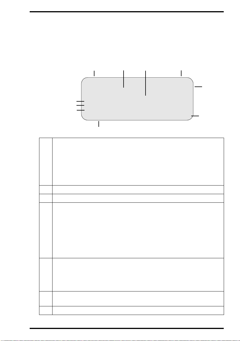
The user interface
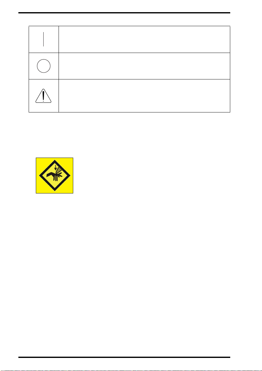
Main components of the Digit iz er
Cassette
output buffer
Keypad
with display
Service connector
Status indicator
Cassette
input buffer
Main switch
The main components of the Centricity™ MP3510 are:
n Cassette input buffer
The cassette input buffer accepts up to 10 cassettes - even of different sizes for digitizing and up to 9 cassettes for erasure.
n Keypad
As the handling of the cassettes is fully automated, normal operation is a
zero-button operation. The keys on the keypad are only used to activate
special functions such as reading an emergency image plate or erasing an
image plate.
n Status indicator
A light indicates the status of the Centricity™ MP3510.
14
5000A EN 20020315
Page 15

n Cassette output buffer
The cassette output buffer receives cassettes which have been handled by
the Digitizer.
5000A EN 20020315
15
Page 16

The control panel
The control panel of the Centricity™ MP3510 consists of a backlit LCD
display and 10 keys.
As the handling of the cassettes is fully automated, normal operation is a
zero-button operation. Only when you are performing special functions or in
the event of problems (e.g. a cassette or image plate jam), will you need the
keys.
16
5000A EN 20020315
Page 17
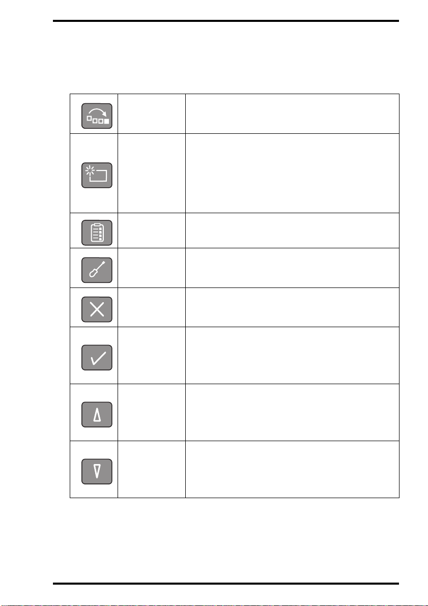
The keypad
Special functions can be accessed via the keypad. The keypad features the
following keys:
Emergency
key
Erase key
Key-operator
key
Service key
Escape key
Confirm key
Up key
To give an image the st atus ‘ emerge ncy’ whe n it i s
sent to the image processing station.
To erase images without digitizing them.
This must be done if:
• an image plate h as no t been u sed for mo re than
3days;
• an image plate has been exposed to an
exceptionally high X-ray dose.
To access advanced functions (‘key-operator
functions’).
To access service-level functions.
Reserved for trained service personnel.
To quit the current function or exit a menu without
saving modifications.
In key-operator mode:
• to select a menu.
• to accept an entry in a menu and go back to
operator mode.
• To move the cursor to the previous entry field.
• To scroll upwards.
• To increment the number in a numeric entry
field.
5000A EN 20020315
Down key
• To move the cursor to the next entry field.
• To scroll downwards.
• To decrement the number in a numeric entry
field.
17
Page 18

Left key
Right key
• To scroll backwards throug h multiple choices
within a field.
• To move the entry position in a numerical entry
field from right to left.
• To toggle between values in a field.
• To scroll forwards through multiple choices
within a field.
• To move the entry position in a numerical entry
field from left to right.
• To toggle between values in a field.
18
5000A EN 20020315
Page 19
The display
The Centricity™ MP3510 control panel has a backlit LCD display with 8 lines
of 40 characters each. Its lay-out depends on the operating mode.
n In operator mode, the display has dedicated areas for specific information:
1
1
Set-up STATUS
8.1
Patient_Last_Name Sub_Exam
8.2
Patient_Last_Name Sub_Exam
8.3
Patient_Last_Name Sub_Exam
Station Name ERROR
7
1
Set-up of image processing st a tio n:
24
1ST MESSAGE
2nd Message
3
OPERATION MODE
• [blank]: Default image processing station selected.
• Off line: T r ans mis sio n t o all image proc es sing stations disabled.
• [process.station] not ready: Image processing station not available.
• [process.station] rerouted: Images rerouted to other image processing
station.
2 Type of message
3 Extra comment or action to take
4 System status :
• READY: The Centricity™ MP3510 is ready for operation.
• BUSY: The Centricity™ MP3510 is busy with scanning or erasing.
• ERROR: An error has occurred. Refer to
maintenance and troubleshooting’
Chapter 4, ‘Preventive
.
• LOCKED: id.
• WARNING: id.
5
Operation mode:
• [blank]: Normal operation mode.
• EMERGENCY: Emergency function for image plates with ID data.
• ERASURE: Re-erasure function.
Error status: service code (SERVICE XXXXX) or error code (CODE
6
XXXXX)
7
Station name of the Centricity™ MP3510
5
6
5000A EN 20020315
19
Page 20
Identifier of image plate being treated:
8.1
After image ID data is read;
8.2
During scanning of image plate and transmittal of image data;
8.3
During transmittal of image data to image processing station.
If the system has been idle for 5 minutes, the backlit LCD display dims. The
display lightens if:
• The display message changes, e.g. if the Digitizer receives a message from the
image processing station.
• You place a cassette in the input buffer.
• You press a key on the keypad.
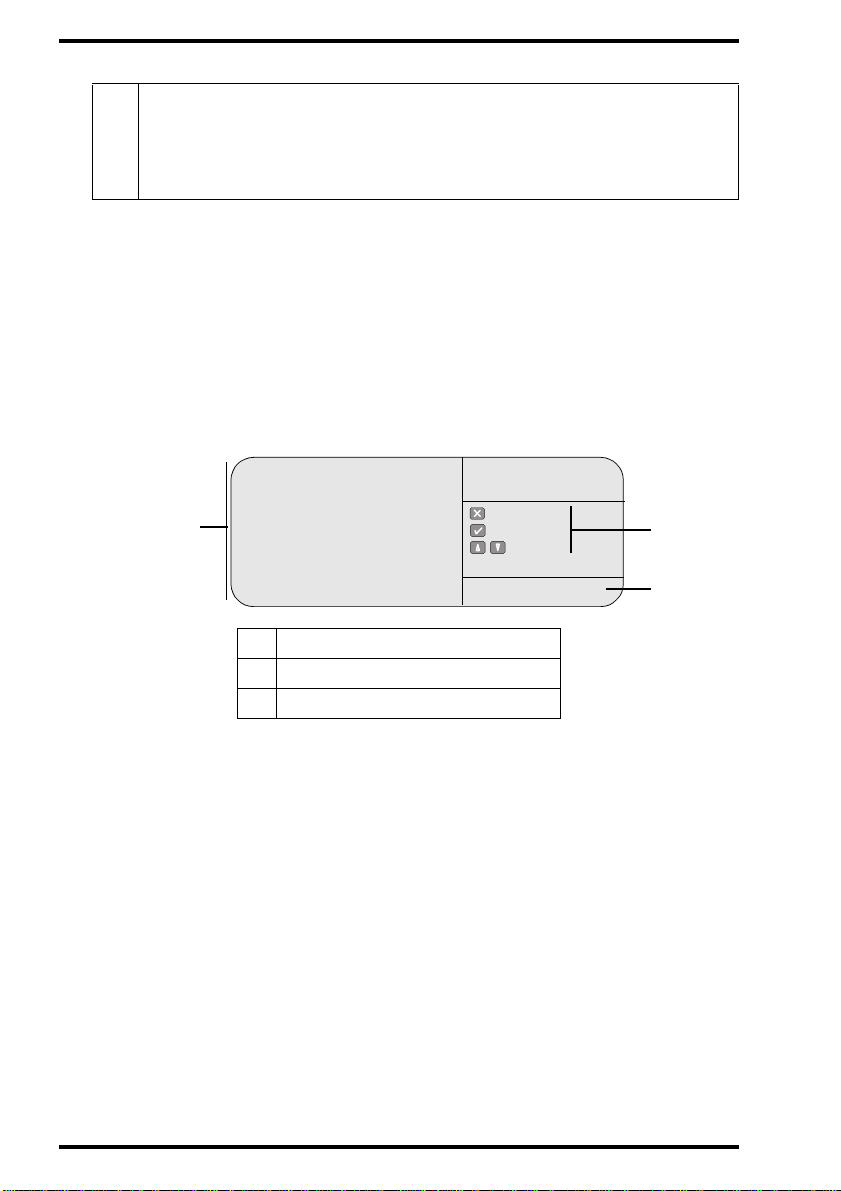
n In key-operator mode, operation is menu driven. The menu displays the
key-operator functions, the active keys, and the service code.
Queue management
Digitizer set-up
Date and Time
1
Send test image
System info
Install
Save confi gu r ation
Fast preview
1
Key-operator functions
2
Active keys
3
Service code
KEY -OPERATOR
MENU
: quit
: ok
: select
SERVICE XXXXX
2
3
20
5000A EN 20020315
Page 21

The status indicat or
The light at the top of the Centricity™ MP3510 indicates the status of the
Centricity™ MP3510.
Color
Green
Red
Constant/
Flashing
Constant
Flashing
Constant
Flashing
Status Action
Ready. Proceed.
Busy (treating image
plate).
Proceed.
• Check display for messages.
Error.
• Refer to
in case of malfunction’
page
• Locked or warning.
• Power on/self-test
in progress.
• Key-operator mode.
• Service mode.
• Centricity™
• Check display for messages.
• Refer to
in case of malfunction’
page
MP3510 not
connected to i mage
processing device.
‘General procedure
77
.
‘General procedure
77
.
on
on
5000A EN 20020315
21
Page 22

Audio signa ls
The Centricity™ MP3510 gives status information via beeps. The length of
the beep indicates the response of the system to a key command.
• A short beep means that Centricity™ MP3510 has accepted the key
command and is starting the operation.
• A long beep means that you have pressed a non-active key or that the
Centricity™ MP3510 has rejected the key command.
• An interval beep accompanies an error, locked or warning message. Refer to
Chapter 4, ‘Preventive maintenance and troubleshooting’
.
22
5000A EN 20020315
Page 23
Switching on t h e Centricity™ MP3510
Before switching on
Make sure that the following conditions are met before you switch the
Centricity™ MP3510 on:
• A service technician has appropriately connected the Centricity™ MP3510 and
has carried out a perfor m ance test.
• You have read the safety precautions at the beginni ng of this manual and you
will observe them while work ing with the Centricity™ MP3510.
• You are acquainted with the basic functions of the Di gitizer.
Switching on the Centricity™ MP3510
Locate the main switch and place it in position ‘ON’.
After the Digitizer has been switched on, the fol lowing screen is displayed:
WAIT
Self test proceeding
The Centricity™ MP3510 executes a self-test, ini ti a lizes all the Digitize r
components, goes through a start-up procedure and checks for cassettes, image
plates and images still to be transmitted in the image queue. During this stage, the
status indicat or is red and flashing.
5000A EN 20020315
23
Page 24

If the Centrici ty™ MP35 10 has comp lete d the sel f-tes t succ essful ly, the Centricity™
MP3510 enters the oper ator mode and displays the main operator screen:
READY
MP3510
The status indicator is constant green. The Centricity™ MP3510 i s ready for use.
v
If the Centricity™ MP3510 displays:
ERROR
Self test failed
SERVICE XXXXX
An error has occurred during the self-test. Refer to Chapter 4, ‘Preventive
maintenance and troubleshooting’.
24
5000A EN 20020315
Page 25
Switching off the Centricity™ MP3510
Before switching off
Check that the Centricity™ MP3510 is not scanning an image plate. If the
Centricity™ MP3510 is scanning an image plate, the status indicator at the
top of the machine is green and flashing.
Switching off
It is recommended to switch off the Centricity™ MP3510 at the end of the
day.
Only switch off the Centricity™ MP3510 if you do not intend to digitize
emergency image plat es over night . Swi tchin g on t he Cent ricit y™ MP 3510
takes a few minutes. Du ring this time emergency di gitizing is not
possible!
Place the main switch in position ‘OFF’.
5000A EN 20020315
25
Page 26
Resetting the Digitizer
In exceptional circumstances you may be prompted to reset the Centricity™
MP3510 - either by a message on the keypad or as part of a troubleshooting
procedure in this manual.
Never reset the Digitizer to solve a plate or cassette jam . If you would do
so, the plate inside the Digitiz er might get damaged. In case of a plat e or
cassette jam, always foll ow the procedures describe d in Chapter 4,
‘Preventive maintenance and troublesh oot ing’ .
To reset the Digitizer:
1 Locate the main switch and place it in position ‘OFF’.
2 Wait 30 seconds.
3 Place the main switch in position ‘ON’.
26
5000A EN 20020315
Page 27

Chapter
Basic operation
(‘Operator mode’)
This chapter provides basic information on how to digitize
image plates under normal conditions and in emergency
situations. It also treats how to erase an image plate to
prevent ghost images caused by previous exposures or by
scattered radiation. These functions are available in
operator mode.
2
q Reading an image plate
q Reading an emergency image plate
q Re-erasing an image plate
Page 28

Reading an image plate
The main function of the Centricity™ MP3510 is digitizing image plates and
transmitting the digital image data to the preview station and the image
processing station.
To read one or more image plates:
1 Make sure the cassette has been properly identified via the ID Station.
Refer to the User manual of the ID Software.
2 Check that the Centricity™ MP3510 is ready for operation:
• the Centricity™ MP3510 mu st di splay the oper at or scr een wi th ‘R eady’ or ‘B usy ’
status.
QS not ready READY
MP3510
Status field
• the status indicator at the top of the Centricity™ MP3510 must be constant or
flashing green.
v
The Centricity™ MP3510 is operational if the status field equals
‘READY’, even if status messages of the destination are s hown (e.g. ‘ QS
not ready’).
28
5000A EN 20020315
Page 29

3 Place one or more cassettes in the input buffer.
You can insert up to 10 cassettes, even of different sizes. Make sure that the
cassette opening mechanism is at the bottom.
The Digitizer automatically takes in the first cassette, reads the image plate, and
forwards the digital image data to the pr eview station for fas t precheck and to the
image processing station for image process ing.
If fast preview is enabled, the Centricity™ MP3510 transmits the digital image data
in blocks of typical 100 lines to the preview station.
When the Centricity™ MP3510 has treated the cassette, it displays t he operator
main screen.
4 Remove the cassette(s) from the output buffer.
When the Centricity™ M P 35 10 returns the cassette, it is rea dy t o be r eused immediately. However, if you leave it for more than 3 days before
re-using it, you must re-erase it first. Refer to ‘Re-erasing an image
plate’ on page 32.
5000A EN 20020315
29
Page 30

Reading an emergency image plate
Y ou may hav e an image plate which you wish to give priority over other image
plates which are being processed by the image processing station. Such
image plates are referred to as ’emergency image plates’.
The emergency status will only be assigned to the first image plate
which you insert into the Ce nt ri ci t y™ MP3510 cassette slot af te r
pressing the Emergency key.
To read an emergency image plate:
1 Check that the Centricity™ MP3510 is ready for operation:
• the Centricity™ MP3510 mu st di splay the oper at or scr een wi th ‘R eady’ or ‘B usy ’
status.
QS not ready READY
MP3510
Status field
• the status indicator at the top of the Centricity™ MP3510 must be constant or
flashing green.
v
The Centricity™ MP3510 is operational if the status field equals
‘READY’, even if status messages of the destination are s hown (e.g. ‘ QS
not ready’).
2 Press the Emergency key on the keypad.
The display will read:
READY
Next cassette gets emer g ency status
WARNING
MP3510
EMERGENC Y
30
5000A EN 20020315
Page 31

3 Place the cassette you want to give emergency status first in the stack of
cassettes in the input buffer.
Do not place the cassette with emergency status in the stack while the
v
input mechanism is busy getting a cassette from the stack.
v
If you do not enter a cassette within 1 minute after pressing the
Emergency key , the Centricity™ MP 3510 will quit the emergency function
and return to the operator main screen.
If fast preview is enabled, the Centricity™ MP3510 transmits the digital image
data in blocks of typical 100 lines to the preview station.
When the Centricity™ MP3510 has read the identification data of the
emergency cassette, it displays the operator main screen. The Digitizer
resumes processing the remaining cassettes in the cassette input buffer.
If you decide not to assign emergency status to a cassette after having
pressed Emergency, you can quit the Emergency function by either pressing
Escape or by pressing the Emergency key a second time (‘toggle’ key).
If a ‘WARNING’ or ‘LOCKED’ message is displayed during the
v
Emergency procedure, the Centricity™ MP3510 will not quit the
Emergency mode. Refer to Chapter 4, ‘Preventive maintenance and
troubleshooting’.
4 Remove the cassette from the output buffer.
5000A EN 20020315
31
Page 32

Re-erasing an image plate
At the end of a normal or emergency digitiz ing cycle, the Centricity™ MP 3510
returns an erased imag e plate. However, in the following cases, you must re-
erase the image plate before re-using it in order to prevent ghost images from
interfering with the image of interest:
• If the image plate has not been used for more than 3 days.
In this case, the image plate may have been exposed to scattered radiation.
• If an image plate has been exposed to an exceptionally high X-ray dose.
In this case, deep layers of the im ag e plate may still retain a latent image after
standard erasure. Leave the image plate to rest at least one day before reerasing it.
You can erase image plates which you have given the status ‘to be erased’
via the ID Station or image plates which have the status ‘erased’. You can
erase an image plate or a batch of up to 9 plates.
Re-erasing image plates with status ‘erased’
To erase one or more image plates which have been erased as part of a
normal or emergency digitizing cycle:
1 Check that the Centricity™ MP3510 is ready for operation:
• the Centricity™ MP3510 mu st di splay the operat or scr ee n with ‘ Rea dy’ or ‘Busy ’
status.
32
READY
MP3510
Status
• the status indicator at the top of the Centricity™ MP3510 must be constant or
flashing green.
5000A EN 20020315
Page 33

2 Press the Erase key on the keypad.
The display will read:
READY
The next cassette(s) will be erased
WARNING
Enter number of cassettes to erase: #
Put cassette(s) in input buffer or
press to quit.
ERASURE
3 Use the Up and Down keys to set the number of image plates to be erased.
The default value is 1; the maximum is 9.
4 Place the cassettes which you want to erase in the cassette input buffer.
After a cassette has been erased, the # digit on the display decreases.
While erasing, the Centricity™ MP3510 will still display the above screen and the
status indicator will be green flashing. When t he Centricity™ MP3510 has erased
the image plate, it displ ays the operator main screen.
You can now add (exposed) cassettes to the batch of cassettes. The Digitizer will
only erase as many cassettes as you have specified.
If you place fe wer ca ssett es in t he ca ssett e input buf fer than you ha ve spe cified , the
Digitizer will erase the cas settes in the buffer and revert to normal mode after a
time-out of 1 minute.
5000A EN 20020315
33
Page 34

You can quit the Erase function by either pressi ng Esc ape or by pr essi ng t he Erase
key a second time (‘toggl e’ key).
Warning
If the above screen is not di splayed but the display reads:
LOCKED
ERASE “PATIENT NAME”?
Press to erase or to scan
ERASURE
You have entered an identified cassette not having the status ‘erased’. You now
have the choice: either cancel erasing or erase the image plate.
• To cancel erasing and make a regular scan: press the Escape key.
• To erase the image plate: press the Confirm key.
While erasing, the Centr ic it y™ MP3510 will display:
WARNING
The next cassette(s) will be erased
Enter number of cassettes to erase: #
Put cassette(s) in input buffer or
press to quit.
When the Centricity™ MP35 10 has erased the image plate, it di splays the
operator main screen.
5 Remove the cassette(s) from the output buffer.
34
READY
ERASURE
5000A EN 20020315
Page 35

Re-erasing image plates with sta tus ‘to be erased’
To re-erase one or more image plates which you have given the status ‘to be
erased’ via the ID station:
1 Check that the Centricity™ MP3510 is ready for operation:
• the Centricity™ MP3510 must display the operator screen with ‘Ready’ or
‘Busy’ status.
READY
MP3510
Status
• the status indicator at the top of the Centricity™ MP3510 must be constant or
flashing green.
2 Place the cassettes in the input buffer.
The Centricity™ MP3510 will automatically erase the image plates. The display will
read:
BUSY
* * * ERASING * * *
When the Centricity™ MP3510 has erased the image plat es, it displays the
operator main screen.
3 Remove the cassette(s) from the output buffer.
5000A EN 20020315
35
Page 36

36
5000A EN 20020315
Page 37

Advanced operation
(‘Key-operator mode’)
This chapter covers the following topics:
Chapter
3
q Consulting the image transmission queue (‘Queue management’)
q Customizing the Centricity™ MP3510 (‘Digitizer set-up’)
q Setting the date and time
q Sending test images
q Consulting information on the Centricity™ MP3510
q Installing a new software version
q Installing a new language
q Installing new customer parameters
q Saving the configuration data on a diskette (backup)
q Enabling/disabling fast preview
Page 38

Consulting the image transmission queue
(‘Queue management’)
As soon as the ID data of an image plate is read, the image identi fier is stored
in a queue. This queue contains information about which images are being
transmitted to a certain image processing station (‘destination’) and their
status. In key-operator mode, you can view this information and erase images
from the image transmission queue.
Consulting the images in the queue
To view which images are being transmitted to a certain image processing
station:
1 In the key-operator main menu, select ‘Queue management’ via the Up and
Down keys and confirm.
38
Queue management
Digitizer set-up
Date and Time
Send test image
System info
Install
Save configuration
Fast preview
KEY-OPERATOR
MENU
: quit
: ok
: select
SERVICE XXXXX
The Centricity™ MP3510 will display a list of installed image processing st ations
and the number of images sent to each:
Name of image processing
Number of images
station
[PPname1] #
[PPname2] #
[PPname3] #
QUEUE
MANAGEMENT
: quit
: ok
: select
SERVICE XXXXX
5000A EN 20020315
Page 39

2 Select the image processing station of your choice via the Up and Down keys
and confirm.
The Centricity™ MP3510 wi ll display th e list of imag es sent to the ima ge processing
station and th eir status ‘S’:
Miller S
Johnson S
Waterson S
Palin S
QUEUE
MANAGEMENT
: quit
: ok
: select
SERVICE XXXXX
The status ‘S’ of an im age is either:
‘S’ Status Meaning
Q In queue
Image is waiting in queue to be transmitted.
Image is being transmitted;
TTransmitting
Centricity™ MP3510 is waiting for acknowledgment.
W Warning
Problem with image processing station.
E Exception Problem with image, cannot be transmitted.
[blank] ok
Image has been transmitted successfully.
3 To return to the key-operator main menu, press the Escape key twice.
4 To go to the operator main screen, press the Confirm key.
5000A EN 20020315
39
Page 40

Deleting images from the queue
To delete an image from the queue of images which are waiting to be sent to
a specific image processing station, proceed as in
transmission queue (‘Queue management’)’
‘Consulting the image
on page38 (steps 1 to 2).
Subsequently, do the following:
1 In the list of images being sent to the image processing station, select the
image which you want to delete via the Up and Down keys.
Miller Q
Johnson Q
Waterson Q
Palin Q
2 Press the Erase key.
The Centricity™ MP3510 will di splay:
WARNING
Delete the selected
image from queue?
Miller
v
You can only erase images with s t atus ‘Q ’ (in queue), ‘ W’ (warning) or ‘E’
(exception).
QUEUE
MANAGEMENT
: quit
: ok
: select
SERVICE XXXXX
QUEUE
MANAGEMENT
: quit
: ok
: select
SERVICE XXXXX
40
5000A EN 20020315
Page 41

3 To erase the image, press the Confirm key.
To ca ncel erasing, press the Escape key.
After the image has been erased, the Queue management screen is displayed
again:
Johnson Q
Waterson Q
Palin Q
QUEUE
MANAGEMENT
: quit
: ok
: select
SERVICE XXXXX
4 To return to the list of installed image processing stations, press the Escape
key.
5 To return to the key-operator main menu, press the Escape key.
5000A EN 20020315
41
Page 42

Customizing the Centricity™ MP3510
I
(‘Digitizer set-up’)
Via the Digitizer set-up function in key-operator mode, you can:
• enable or disable the transmittal of images to all image processing stations;
• reroute images to another image processing station (‘destination’);
• enable or disable all audio signals.
Enabling/disabling image transmission
1 In the key-operator main menu, select ‘Digitizer set-up’ via the Up and Down
keys and confirm.
Queue management
Digitizer set-up
Date and Time
Send test image
System info
Install
Save configuration
Fast preview
KEY-OPERATOR
MENU
: quit
: ok
: select
SERVICE XXXXX
The Centricity™ MP3510 will di splay the Digitizer set-up menu:
mage
transmission
field
v
If you do not press a key within 1 minute, the Centricity™ MP3510 will
Process.station: ena bled
Reroute process.sta tion
[PPname1]
to
[PPname2]
Acoustic signal: enabled
DIGITIZER
SET-UP
: quit
: ok
: select
: change
SERVICE XXXXX
exit the key-operator mode.
42
5000A EN 20020315
Page 43

2 Select the Image transmission field via the Up and Down keys.
3 Enable or disable the image transmission via the Left and Right keys.
4 Confirm your choice.
The operator main screen is displayed.
5000A EN 20020315
43
Page 44

Changing the destination
If an image processing station is out o f operation, you can reroute the imag es
to another image processing station. Start as in
transmission’
on page42:
‘Enabling/disabling image
1 In the key-operator main menu, select ‘Digitizer set-up’ via the Up and Down
keys and confirm.
Queue management
Digitizer set-up
Date and Time
Send test image
System info
Install
Save configuration
Fast preview
KEY-OPERATOR
MENU
: quit
: ok
: select
SERVICE XXXXX
The Centricity™ MP3510 will di splay the Digitizer set-up menu:
Process. station: enab l ed
Source rerouting
field
Target rerouting
Reroute process.station
[PPname1]
to
[PPname2]
field
Acoustic signal: enabled
v
If you do not press a key within 1 minute, the Centricity™ MP3510 will
DIGITIZER
SET-UP
: quit
: ok
: select
: change
SERVICE XXXXX
exit the key-operator mode.
2 Select the Source rerouting field via the Up and Down keys.
3 Select the image processing station from which you want to redirect the
images via the Left and Right keys.
You can only redirect the images of one image processing station.
v
4 Select the Target rerouting field via the Up and Down keys.
44
5000A EN 20020315
Page 45

5 Select the image processing station to which you want to redirect the images
via the Left and Right keys.
6 Confirm your choice.
The operator main screen is displayed.
5000A EN 20020315
45
Page 46

Enabling/disabling all audio signals
To enable or disable all audio signals, start as in
transmission’
on page42:
‘Enabling/disabling image
1 In the key-operator main menu, select ‘Digitizer set-up’ via the Up and Down
keys and confirm.
Queue management
Digitizer set-up
Date and Time
Send test image
System info
Install
Save configuration
Fast preview
The Centricity™ MP3510 will di splay the Digitizer set-up menu:
Process.station: enabled
Reroute pr o cess.station
Audio signal
field
Acoustic signal: enabled
KEY-OPERATOR
: quit
: ok
: select
SERVICE XXXXX
[PPname1]
to
[PPname2]
MENU
DIGITIZER
SET-UP
: quit
: ok
: select
: change
SERVICE XXXXX
v
If you do not press a key within 1 minute, the Centricity™ MP3510 will
exit the key-operator mode.
2 Select the Audio signal field via the Up and Down keys.
3 Enable or disable the audio signals via the Left and Right keys.
4 Confirm your choice.
The operator main screen is displayed.
46
5000A EN 20020315
Page 47

Setting the date and time
To set the clock of the Centricity™ MP3510:
1 In the key-operator main menu, select ‘Date and time’ via the Up and Down
keys and confirm.
Queue management
Digitizer set-up
Date and Time
Send test image
System info
Install
Save configuration
Fast preview
KEY-OPERATOR
MENU
: quit
: ok
: select
SERVICE XXXXX
The Centricity™ MP3510 will display the Date and time menu:
Format:
YY- MM- DD HH : MM: SS
02 -01 - 26 14 : 24 : 58
v
If you do not press a key within 1 minute, the Centricity™ MP3510 will
DATE AND
TIME
: quit
: ok
: tab
: inc. dec.
SERVICE XXXXX
exit the key-operator mode.
2 Set the date and time:
• Use the Left and Right keys to select the digit you want to change (‘tab’);
• Use the Up and Down keys to set the digit to the desired value (‘inc . dec.’).
3 Confirm the date and time.
The operator main screen is displayed.
5000A EN 20020315
47
Page 48

Sending test images
To check the communication between the Centricity™ MP3510 and the
image processing station, you can send a test image from the Digitizer to the
image processing station.
To send a predefined test image to a specific image processing station:
1 In the key-operator main menu, select ‘Send test image’ via the Up and Down
keys and confirm.
Queue management
Digitizer set-up
Date and Time
Send test image
System info
Install
Save configuration
Fast preview
KEY-OPERATOR
MENU
: quit
: ok
: select
SERVICE XXXXX
The Centricity™ MP3510 will di splay the Send test image menu:
SEND
TEST IMAGE
To process.station:
[PPname1]
v
If you do not press a key within 1 minute, the Centricity™ MP3510 will
: quit
: ok
: change
SERVICE XXXXX
exit the key-operator mode.
2 Select the image processing station to which you want to send the test image
via the Left and Right keys.
3 Confirm your choice.
48
The Centricity™ MP3510 wi ll return to the operator screen.
5000A EN 20020315
Page 49

Consulting information on the Centricity™
MP3510
Via the System info function in key-operator mode, you can consult:
• the device data of the Centr icity™ MP3510;
• the network parameter s of the Centricity™ MP3510.
Consulting the device settings
1 In the key-operator main menu, select ‘System info’ via the Up and Down
keys and confirm.
Queue management
Digitizer set-up
Date and Time
Send test image
System info
Install
Save configuration
Fast preview
KEY-OPERATOR
MENU
: quit
: ok
: select
SERVICE XXXXX
The Centricity™ MP3510 wi ll display the System info menu:
Device info
Network info
SYSTEM INFO
: quit
: ok
: select
SERVICE XXXXX
5000A EN 20020315
49
Page 50

2 In the System info menu, select ‘Device info’ via the Up and Down keys and
confirm.
The Centricity™ MP3510 will di splay the Device info menu, e.g.:
DEVICE INFO
Station:COMPP1
S/N: 1024
AE-title:COMMP
Software:ACP_XXXX
Total cycles: 34567
26-JAN-2002 14:24:58
The Device info menu provides the following informa ti on:
Station Device name of Centricity™ MP3510
S/N
AE-title
Serial number Centricity™ MP3510: 5145 ‘S/N’
COMMP
Software Software version of Centricity™ MP3510
: ok
SERVICE XXXXX
Total cycles
Total number of image plates which the Centricity™
MP3510 has treated
Date Time and date indication of Centricity™ MP3510 clock
3 To return to the key-operator main menu, press the Escape key twice.
To go to the operator main screen, press t he Confirm key.
50
5000A EN 20020315
Page 51

Consulting the network sett ings
1 In the key-operator main menu, select ‘System info’ via the Up and Down
keys and confirm.
Queue management
Digitizer set-up
Date and Time
Send test image
System info
Install
Save configuration
Fast preview
KEY-OPERATOR
MENU
: quit
: ok
: select
SERVICE XXXXX
The Centricity™ MP3510 wi ll display the System info menu:
Device info
Network info
SYSTEM INFO
: quit
: ok
: select
SERVICE XXXXX
2 In the System info menu, select ‘Network info’ via the Up and Down keys and
confirm.
The Centricity™ MP3510 wi ll display the Network info menu, e.g.:
Hostname: COMPP1
IP-addr: 192.9.200.201
Netmask: 255.255.255.0
D-Router: 192.9.200.254
Mail-Host: 192.9.200.210
NETWORK INFO
: ok
SERVICE XXXXX
The Network info menu provides the following information:
Hostname
IP-address
5000A EN 20020315
Name of host computer to which Centricity™ MP3510 is
connected
IP address of the Centricity™ MP3510
51
Page 52

3 To return to the key-operator main menu, press the Escape key twice.
To go to the operator main screen, press t he Confirm key.
52
5000A EN 20020315
Page 53

Installing a new soft ware version
Via this key-operator function you can copy a new software version from a
floppy disk to the hard disk of the Centricity™ MP3510 and activate the new
software.
When an error occurs during installation, refer to Chapter 4, ‘Preventive
v
maintenance and troubleshooting’.
To install a new software version:
1 Check that the Centricity™ MP3510 is not scanning an image plate.
If the Centricity™ MP3510 is scanning an image plate, the status indicator at the
top of the machine is green and flashing.
2 In the key-operator main menu, select ‘Install’ via the Up and Down keys and
confirm.
Queue management
Digitizer set-up
Date and Time
Send test image
System info
Install
Save configuration
Fast preview
KEY-OPERATOR
MENU
: quit
: ok
: select
SERVICE XXXXX
The Centricity™ MP3510 will display the Install menu:
Software
Language
Configuration
INSTALL
: quit
: ok
: select
SERVICE XXXXX
3 In the Install menu, select ‘Software’ via the Up and Down keys and confirm.
5000A EN 20020315
53
Page 54

The Centricity™ MP3510 will di splay the Install software menu:
Please open the machine
front and insert the
first floppy ACP_ XX X X in
diskette drive and
press
INSTALL
SOFTWARE
: quit
: ok
SERVICE XXXXX
4 Open the left front door of the Digitizer.
Make sure you open the left front door first. When you open the left front door, the
power supply of all critical components is switched off automatically .
5 Insert the first floppy with the new Centricity™ MP3510 software in the disk
drive.
54
5000A EN 20020315
Page 55

6 Press the Confirm key.
The Centricity™ MP3510 will display:
INSTALL
Checking
the volume label . . .
Volume is
<label>
Please wait . . .
copying
A:\.....
to
E:\.....
SOFTWARE
: quit
: ok
SERVICE XXXXX
INSTALL
SOFTWARE
: quit
: ok
SERVICE XXXXX
7 If the Centricity™ MP3510 displays the screen below, insert the second
software floppy:
INSTALL
Please insert the
floppy ACP_XXXX_2
and press
SOFTWARE
: quit
: ok
XXXX = software version
SERVICE XXXXX
Proceed identically for the remaining floppy disks.
After the last floppy, the Centricity™ MP3510 displays following scree n:
INSTALL
Please remove the floppy
and press
5000A EN 20020315
SOFTWARE
: quit
: ok
SERVICE XXXXX
55
Page 56

8 Remove the floppy from the disk drive and press the Confirm key.
Following screen will be displayed:
INSTALL
extracting. . .
E:<file name>
to
C:<file name>
SOFTWARE
: quit
: ok
SERVICE XXXXX
9 Wait until the Centricity™ MP3510 displays:
SW successfully
installed
To initialize the new SW
a reset is necessary
to reset now
Press
INSTALL
SOFTWARE
: quit
: ok
SERVICE XXXXX
10 To make the new software operational, press the Confirm key.
The Centricity™ MP3510 will restart automatically. After 3 minutes it will display:
New software detected.
You should refresh your
backup now.
Please insert the backup
floppy and press
You must make new backup files with the machine specific configuration data.
INSTALL
SOFTWARE
: quit
: ok
SERVICE XXXXX
56
5000A EN 20020315
Page 57

11 Insert an empty formatted floppy into the disk drive and press the Conf irm k ey.
The Centricity™ MP3510 wi ll start copying the machine specific configurat ion data
while displaying the Save configuration screen:
SAVE
copying . . .
D:\ACP_<serial#>.zip
to
A:<path><file name>
CONFIGURATION
: quit
: ok
SERVICE XXXXX
12 When the screen below is displayed, note down the serial number, the date,
and the software version.
Machine configuration
saved. Label the floppy:
Backup MP3510
S/N: <serial#>
Date: <date>
SW version: AC P_XXXX
Please remove the floppy
and press
SAVE
CONFIGURATION
: quit
: ok
SERVICE XXXXX
13 Remove the floppy from the disk driv e a nd label it with the data fr om th e screen.
14 Store the Centricity™ MP3510 software floppies and the backup floppy in the
storage box.
15 Close the front doors.
The Centricity™ MP3510 will restart automa tically.
After start-up, the operator main screen is displayed.
5000A EN 20020315
57
Page 58

Installing a new language
Via this key-operator function you can copy new language files from a floppy
disk to the hard disk of the Centricity™ MP3510 and activate the new
language(s).
When an error occurs during installation, refer to Chapter 4, ‘Preventive
v
maintenance and troubleshooting’.
To install new languages:
1 Check that the Centricity™ MP3510 is not scanning an image plate.
If the Centricity™ MP3510 is scanning an image plate, the status indicator at the
top of the machine is green and flashing.
2 In the key-operator main menu, select ‘Install’ via the Up and Down keys and
confirm.
Queue management
Digitizer set-up
Date and Time
Send test image
System info
Install
Save configuration
Fast preview
KEY-OPERATOR
MENU
: quit
: ok
: select
SERVICE XXXXX
The Centricity™ MP3510 will display the Inst all menu.
3 In the Install menu, select ‘Language’ via the Up and Down keys and confirm.
Software
Language
Configuration
58
INSTALL
: quit
: ok
: select
SERVICE XXXXX
5000A EN 20020315
Page 59

The Centricity™ MP3510 will display the Install language menu:
Please open the machine fro nt
and insert the
language floppy ACPLXXXX
and press
INSTALL
LANGUAGE
: quit
: ok
SERVICE XXXXX
4 Open the left front door of the Digitizer.
Make sure you open the lef t front door first. When you open the left front door, the
power supply of all critical components is switched off automatically .
5 Insert the floppy with the new language files in the disk drive.
5000A EN 20020315
59
Page 60

6 Press the Confirm key.
The Centricity™ MP3510 will di splay:
copying . . .
A:<file name>
to
C:<file name>
INSTALL
LANGUAGE
: quit
: ok
SERVICE XXXXX
Language successfully
loaded
Please remove the floppy
and press
INSTALL
LANGUAGE
: quit
: ok
SERVICE XXXXX
7 Remove the floppy from the disk drive and press the Confirm key.
The Centricity™ MP3510 will di splay:
INSTALL
Do you want me to c h an ge
my user terminal
language?
LANGUAGE
: quit
: ok
SERVICE XXXXX
60
5000A EN 20020315
Page 61

8 You have the choice to change the language of the user interface:
• If you do not want to change the language of the user interface, press the
Escape key and proceed with step 10.
• If you want to change the language, press the Confirm key.
The Centricity™ MP3510 will display:
Select from list:
Dutch
English
French
German
Italian
Japanese
Spanish
INSTALL
LANGUAGE
: quit
: ok
: select
SERVICE XXXXX
9 Select the desired language from the list via the Up and Down keys and
confirm
The Centricity™ MP3510 will display:
your choice.
Initializing new
user terminal
language . . .
INSTALL
LANGUAGE
: quit
: ok
SERVICE XXXXX
5000A EN 20020315
61
Page 62

10 Wait until the display reads:
Parameters have changed.
You should refresh your
backup now.
Please insert the backup
floppy and press
INSTALL
LANGUAGE
: quit
: ok
SERVICE XXXXX
You must make new backup files with the new parameters.
11 Insert an empty formatted floppy into the disk drive and press the Con firm ke y.
The Centricity™ MP3510 will start copying the machine specific configuration data
while displaying the Save configuration screen:
SAVE
copying . . .
D:\ACP_<serial#>.zip
to
A:<path><file name>
CONFIGURATION
: quit
: ok
SERVICE XXXXX
12 When the screen below is displayed, note the serial number, the date, and
the software version.
62
Machine configuration
saved. Label the floppy:
Backup MP3510
S/N: <serial#>
Date: <date>
SW version: AC P_XXXX
Please remove the floppy
and press
SAVE
CONFIGURATION
: quit
: ok
SERVICE XXXXX
5000A EN 20020315
Page 63

13 Remove the floppy from the disk drive and label it with the dat a from th e screen.
14 Store the Centricity™ MP3510 language floppy and the backup floppy in the
storage box.
15 Close the front doors.
The Centricity™ MP3510 will restart automatically.
After start-up, the operator main screen will be di splayed.
5000A EN 20020315
63
Page 64

Installing new customer parameters
Via this key-operator function you can copy new customer parameter files
(CPF-files) from a floppy disk to the hard disk of the Centricity™ MP3510 and
activate the new parameters.
When an error occurs during installation, refer to Chapter 4, ‘Preventive
v
maintenance and troubleshooting’.
To install new customer parameters:
1 Check that the Centricity™ MP3510 is not scanning an image plate.
If the Centricity™ MP3510 is scanning an image plate, the status indicator at the
top of the machine is green and flashing.
2 In the key-operator main menu, select ‘Install’ via the Up and Down keys and
confirm.
Queue management
Digitizer set-up
Date and Time
Send test image
System info
Install
Save configuration
Fast preview
KEY-OPERATOR
MENU
: ok
: quit
: select
SERVICE XXXXX
The Centricity™ MP3510 will di splay the Install menu.
3 In the Install menu, select ‘Configuration’ via the Up and Down keys and
confirm.
Software
Language
Configuration
64
INSTALL
: quit
: ok
: select
SERVICE XXXXX
5000A EN 20020315
Page 65

The Centricity™ MP3510 wi ll display the Install configuration menu:
Please open the machine
front, insert the
CPF- floppy in the
diskette drive and
press
INSTALL
CONFIGURATION
: quit
: ok
SERVICE XXXXX
4 Open the left front door of the Digitizer.
Make sure you open the lef t front door first. When you open the left front door, the
power supply of all critical components is switched off automatically .
5 Insert the floppy with the new CPF-files in the disk drive.
5000A EN 20020315
65
Page 66

6 Press the Confirm key.
The Centricity™ MP3510 will di splay:
INSTALL
copying <file name> . . .
Please remove the floppy
and press
CONFIGURATION
: quit
: ok
SERVICE XXXXX
INSTALL
CONFIGURATION
: quit
: ok
SERVICE XXXXX
7 Remove the floppy from the disk drive and press the Confirm key.
Parsing CPF file
Please wait
INSTALL
CONFIGURATION
: quit
: ok
SERVICE XXXXX
8 Wait until the Centricity™ MP3510 displays:
Confirm ID or select new:
SP1001xxxxxxxx1............... 201
SP1001xxxxxxxx2 ...... ...... .. 202
MP3510xxxxxxxx3 ............. 203
SP1001xxxxxxxx4 ...... ...... .. 204
MP3510xxxxxxxx5..............205
SP1001xxxxxxxx6. ...... ...... .. 206
66
INSTALL
CONFIGURATION
: quit
: ok
: select
SERVICE XXXXX
5000A EN 20020315
Page 67

This screen offers you the possibility to change the IP address of the Centricity™
MP3510.
v
If the Centricity™ MP3510 displays the screen below, the image queue is
not empty, and therefore you cannot change the IP address of the
Centricity™ MP3510.
Image queue not empty!
Check the queue then
restart ‘INSTALL
- CONFIGURATION’
Press for queue
management . . .
INSTALL
CONFIGURATION
: quit
: ok
SERVICE XXXXX
Press the Confirm key to co nsult the image transmissi on queue and if necessary
delete the images in the queue. Refer to
42
page
. When the queue is empty, restart the ‘Install - Configuration’ function,
‘Consulting the images in the queue’
refer to step 2.
9 You have the choice whether or not to change the IP address:
• To keep the current IP address, press the Confir m key.
• To change the IP address of the Centricity™ MP3510, select an IP address and
the corresponding na me via the Up and Down keys and confirm.
The Centricity™ MP3510 will display:
INSTALL
Initializing new
station name . . .
CONFIGURATION
: quit
: ok
on
5000A EN 20020315
SERVICE XXXXX
67
Page 68

10 Wait until the Centricity™ MP3510 displays:
Configuration installed.
Parameters have changed.
You should refresh your
backup now.
Please insert the backup
floppy and press
INSTALL
CONFIGURATION
: quit
: ok
SERVICE XXXXX
You must make backup files with the new parameters.
11 Insert an empty formatted floppy into the disk drive and press the Con firm ke y.
The Centricity™ MP3510 will start copying the machine specific configuration data
while displaying the Save configuration screen:
SAVE
copying . . .
D:\ACP_<serial#>.zip
to
A:<path><file name>
CONFIGURATION
: quit
: ok
SERVICE XXXXX
12 When the screen below is displayed, note the serial number, the date, and
the software version.
68
Machine configuration
saved. Label the floppy:
Backup Centricity™ MP3510
S/N: <serial#>
Date: <date>
SW version: AC P_XXXX
Please remove the floppy
and press
SAVE
CONFIGURATION
: quit
: ok
SERVICE XXXXX
5000A EN 20020315
Page 69

13 Remove the floppy from the disk driv e a nd label it with the data fr om th e screen.
14 Store the floppy with the CPF-files of the Centricity™ MP3510 and the
backup floppy in the storage box.
15 Close the front doors.
The Centricity™ MP3510 will restart automatically.
After start-up, the operator main screen will be di splayed.
5000A EN 20020315
69
Page 70

Saving the configuration data on a diskette (backup)
Via the Save configuration function in the key-operator main menu you can
make backup files of the machine specific data.
To make a backup:
1 Check that the Centricity™ MP3510 is not scanning an image plate.
If the Centricity™ MP3510 is scanning an image plate, the status indicator at the
top of the machine is green and flashing.
2 In the key-operator main menu, select ‘Save configuration’ via the Up and
Down keys and confirm.
Queue management
Digitizer set-up
Date and Time
Send test image
System info
Install
Save configuration
Fast preview
KEY-OPERATOR
MENU
: quit
: ok
: select
SERVICE XXXXX
The Centricity™ MP3510 will di splay the Save configuration menu.
SAVE
Please insert the
existing ba ckup floppy
or a new and empty floppy
and press
CONFIGURATION
: quit
: ok
SERVICE XXXXX
70
5000A EN 20020315
Page 71

3 Open the left front door of the Digitizer.
Make sure you open the lef t front door first. When you open the left front door, the
power supply of all critical components is switched off automatically .
4 Insert the backup floppy onto which you want to store the configuration data.
5000A EN 20020315
71
Page 72

5 Press the Confirm key.
The Centricity™ MP3510 will di splay:
SAVE
copying . . .
D:\ACP_<serial#>.zip
to
A:<path><file name>
CONFIGURATION
: quit
: ok
SERVICE XXXXX
6 When the screen below is displayed, note the serial number, the date, and
the software version.
Machine configuration
saved. Label the floppy:
Backup Centricity™ MP3510
S/N: <serial#>
Date: <date>
SW version: AC P_XXXX
Please remove the floppy
and press
SAVE
CONFIGURATION
: quit
: ok
SERVICE XXXXX
7 Remove the floppy from the disk drive and label it with the data fro m the sc reen.
8 Store the backup floppy in the storage box.
9 Close the doors.
The Centricity™ MP3510 will restart automatica ll y.
After start-up, the operator main screen will be di splayed.
72
5000A EN 20020315
Page 73

Enabling/disabling fast preview
If fast preview is enabled, the Digitizer will transmit the digital image data to
the preview station as soon as you have entered the identification data. The
image data are sent in blocks of typical 100 lines. Fast preview permits you to
quickly assess whether the exposure was successful. As soon as the preview
image has been calculated, the fast preview image will be replaced by the
preview image. The fast preview feature may not be supported by your
workstation, or may require a software upgrade of your workst ation. For more
information, contact your local service organization.
Your service engineer can configure which station serves as preview
v
station. Either identifying and previewing images is done on the ID
station, or a dedicated station is reserved for previewing images. For
more information, contact your local service organization.
To enable or disable fast preview:
1 Check that the Centricity™ MP3510 is not scanning an image plate.
2 In the key-operator main menu, select ‘Fast preview’ via the Up and Down
keys.
Queue management
Digitizer set-up
Date and Time
Send test image
System info
Install
Save configuration
Fast preview
3 Confirm your choice.
The Centricity™ MP3510 will display:
5000A EN 20020315
KEY-OPERATOR
MENU
: quit
: ok
: select
SERVICE XXXXX
73
Page 74

Fast preview: enabled
FAST
PREVIEW
: quit
: ok
: change
SERVICE XXXXX
4 Enable or disable fast preview via the Left and Right keys.
5 Confirm your choice.
The operator main screen is displayed.
74
5000A EN 20020315
Page 75

Preventive maintenance and
troubleshooting
This chapter covers the following topics:
Chapter
4
q Preventive maintenance
q General procedure in case of malfunction
q Solving the ‘ERROR’ status
q Clearing cassette jams
q Clearing image plate jams
Page 76

Preventive maintenance
The Centricity™ MP3510 is designed for trouble-free service. Maintenance
and cleaning involve only some minor user tasks.
Interval What to do? Page
Ad hoc
Safety guidelines
To prevent damage to the Digitizer while cleaning, observe the following
safety precautions:
• Do not lubricate the Digitizer.
• Do not attempt to disassemble the Di gitizer.
• Always switch off the Centricity™ MP3510 and disconnect the power cord from
the outlet before carrying out any cleaning work.
Cleaning th e exterior
v
Do not open the machine for cleaning. No components inside the
machine require maintenance or cleaning by the user.
‘Cleaning the exterior ’ 76
1 Switch off the Digitizer by following the procedure as described in
off the Centricity™ MP3510’
on page 25.
‘Switching
2 Remove the power plug from the socket.
3 Wipe the exterior of the Digitizer with a clean, soft, damp cloth.
Use a mild soap or deterge nt i f re qui red bu t ne ver us e an a mmonia–b ase d clean er.
Be careful not to get any liquid in the power cord port.
Take extreme care that no water in fil tr at es t he m achine !
4 Plug in the Digitizer and switch it on by following the procedure as described
in
‘Switching on the Centricity™ MP3510’
76
on page 23.
5000A EN 20020315
Page 77

General procedure in case of malfunction
In exceptional situations the Centricity™ MP3510 display provides
comprehensive information concerning errors and ways of correcting them.
The Digitizer status changes from ‘READY’ to one of the following:
Message
Warning
Locked
Error
Status
indicator
Red
flashing
Red
flashing
Constant
red
Never reset the Digit izer to solve a cassette or image plat e j am nor to
solve communication pr obl em s with the image processing st at ion .
Meaning Action
Follow the instruc t io ns on
Further operation is
possible without imp airing
the image quality.
The Digitizer no longer
takes cassettes from the
input buffer. You can
solve this problem without
resetting the Digitizer.
This status normally
requires service or key
operator intervention.
the display. The warning
disappears as soon as
the problem has been
solved.
Follow the instruc t io ns on
the display.
Follow the instruc t io ns on
the display.
5000A EN 20020315
77
Page 78

Solving the ‘ERROR’ status
Basically, there are two types of errors:
• Errors which can be solved by the key-operator.
Example: Image plate jam. The error field reads ‘ERROR XXXXX’.
• Errors which can only be solve d b y a trained service engineer.
The error field reads ‘SERV ICE XXXXX’.
Solving ‘SERVICE XXXXX’ errors
If the error field reads ‘SERVICE XXXXX’:
1 Reset the Centr icity™ MP3510.
Refer to
2 If the message persists, contact your local service organization and
communicate the error number.
‘Resetting the Digitizer’
Do not attempt to corr ect the error yourself.
on page26.
78
5000A EN 20020315
Page 79

Solving ‘ERROR XXXXX’ errors
If the error field reads ‘ERROR XXXXX’:
1 Check the instructions on the screen.
2 Check whether the display shows the following pictograph:
Cassette position
Plate position
If the above pictograph is displayed, a cassette or an image plate is jammed inside
the Digitizer. The b lank rectangle designates the position of the cassette; the
shaded rectangle designates the position of the image plate.
Do not reset the system .
3 Follow the instructions on the display and the procedures below.The display
will tell you whether you need to open the front doors.
• If a cassette is jammed, refer to
• If an image plate is jammed, refer to
‘Clearing cassette jams’
‘Clearing image plate jams’
on page80.
on page84.
4 If the error condition and attendant message persists, contact your local
service organization and communicate the error number.
5000A EN 20020315
79
Page 80

Clearing cassette jams
A cassette can get jammed when the Centricity™ MP3510 takes in a
cassette or when it returns a cassette to the output buffer. If this is the case,
you see part of the cassette either in the input buffer or in the output buffer.
To clear a cassette jam:
1 Switch off the Centricity™ MP3510.
Refer to
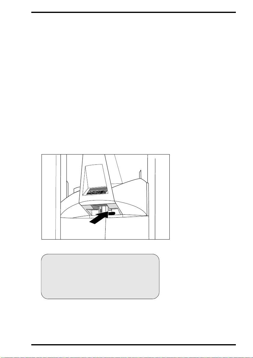
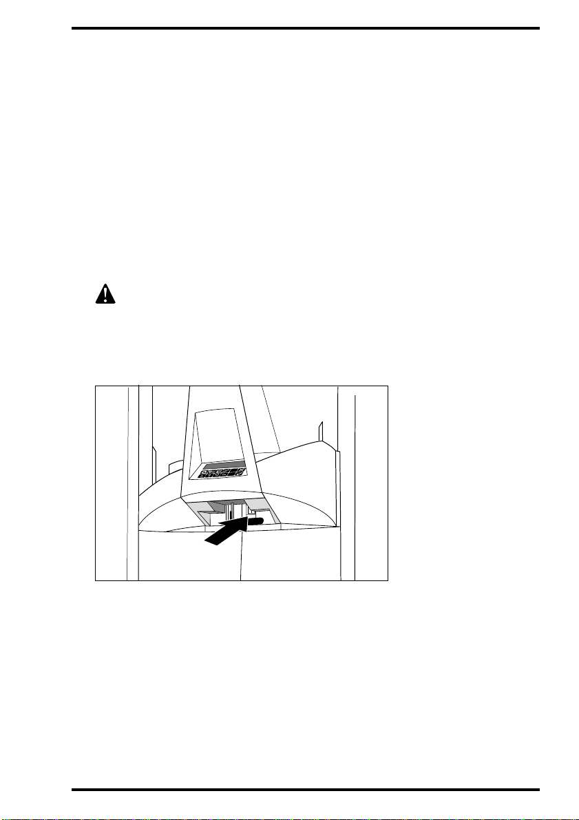
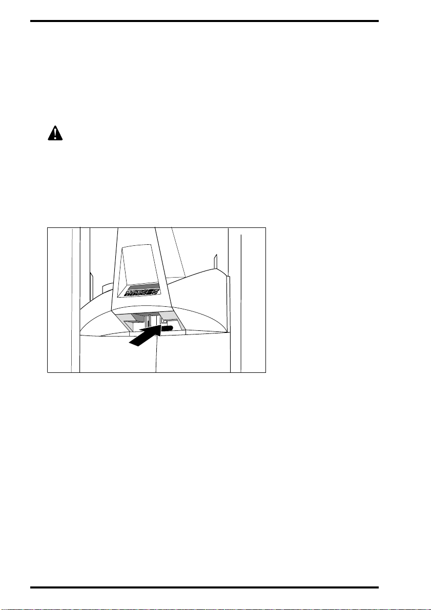
2 Push the black handle located under the control panel gently to the left to
unlock the front doors of the Centricity™ MP3510.
‘Switching off the Centricity™ MP3510’
on page25.
80
5000A EN 20020315
Page 81

3 Open the left front door of the Digitizer.
Make sure you open the lef t front door first. When you open the left front door, the
power supply of all critical components is switched off automatically .
4 Lift the bottom door bolt and open the right front door.
2
1
5000A EN 20020315
81
Page 82

5 Gently remove the jammed cassette.
If the cassette is jammed in the output slot, the cassette might be hard to reach. In
this case, continue with steps 6 to 7.
6 If the cassette is jammed in the output slot and is hard to reach, swivel the
cassette unit anti-clockwise.
82
5000A EN 20020315
Page 83

7 Remove the cassette by pulling it towards you [2] while gently lifting it
upwards [1].
If you cannot easily remove a cassette at th is point, do no t dismantle
the unit any further. Contact your local service organization.
2
1
8 Close the front doors.
The Centricity™ MP3510 will restart automatically.
After start-up, the operator main screen is displayed.
5000A EN 20020315
83
Page 84

Clearing image plate jams
The Centricity™ MP3510 always reads and digitizes the plate first, then
erases it and feeds it to the output buffer. If a plate jam occurs before the
plate is scanned, there is a fair chance that you can recover the image by
putting the image plate back into the cassette and digitizing it again. While
handling the image plate, prevent exposing it to daylight as much as possible.
The diagram below shows the possible locations of a jammed image plate
and the probable status of the image.
84
1
Status Action
Plate jam in the post-scan unit.
1
Image is OK.
Plate jam in the pre-scan unit.
2
Image plate is not erased but
cassette status is set to ‘erased’.
Plate jam in the scanner. Cassette
3
status is set to ‘erased’. Image is
damaged.
2
3
Erase the image plate.
1 Re-identify cassette via ID
Station.
2 Digitize cassette.
1 Erase the image plate.
2 Redo the patient exam.
5000A EN 20020315
Page 85

To clear an image plate jam:
1 Remove the cassette.
Refer to
‘Clearing cassette jams’
on page80.
2 Check whether the image plate is jammed in the pre-scan or in the post-scan
unit.
Refer to the di ag ram above.
• If the image plate is jammed in the pre-scan unit, continu e with step 3.
• If the image plate is jammed in the post-scan unit, continue with step 4.
3 If an image plate is jammed in the pre-scan unit, remove the jammed image
plate by pulling it carefully towards you.
If the image plate cannot be removed by pulling it towar ds you, lift the jammed p late
and remove it through the upper part of the Digitizer.
5000A EN 20020315
85
Page 86

4 If an image plate is jammed in the post-scan unit, try to remove the jammed
image plate by pulling it carefully towards you.
If the access is too narrow, lift the jammed plate over the erase unit and remove it
through the upper section of the Digitizer.
If it is still not possible to remove th e image plate, do not dismantle the
unit any further. Contact your local service organization.
5 Close the front doors.
The Centricity™ MP3510 will restart automatica ll y.
After start-up, the operator main screen is displayed.
86
5000A EN 20020315
Page 87

Appendix
Equipment information sheet
A
Page 88

Specifications
Product description
Type of product Digitizer
Commercial name Centricity™ MP3510
Model number 5146/2xx
Manufactured for
Labelling
CE/TÜV
UL
CUL Canada
Dimensions
Length
Width 840 mm
Height 1420 mm
Weight
Unpacked 320 kg
Power consumption
Standby approx. 300 W
GE Medical Systems Information
Technologies, USA
93/42 EEC ‘Medical Devices’
(Europe), EN60601-1, VDE 0750
UL 2601, CSA 22.2 No. 950
(North America)
• at cassette buffer: 1141 mm
• at foot: 840 mm
88
Maximum approx. 1700 W (=8.5 A)
Self-adapt ing power su pply range
• 200 V (-10 %) to 240 V (+10 %)
•50-60Hz
5000A EN 20020315
Page 89

Environmen tal requirements
Room temperature 20 °C - 30 °C
Maximum temperature change 0.5°C/min.
Relative humidity 10 % - 80 %
Magnetic field
Less than 5 Gauss; compliant with
EN 61000-4-8, Level 5
Sunlight exposure Not to be operated in full sunlight
Physical emissions
Noise emission (sound power level according to DIN 45635 Part.27)
• During scanning max.65 dB(A)
• Standby max. 46 dB(A)
Heat emission (at max. throughput with 35 cm x 43 cm image plates)
• Europe 0.8 kWh
• US 2730 BTU/hr
Cassette buffer capacity
10 cassettes of mixed sizes, both in input and output buffer
Performance
Throughput for high resolution 80 plates/h (size dependent)
Throughput for standard resolution 95 plates/h (size dependent)
Grayscale resolution
Data acquisition 12 bits/pixel
Output to processor 12 bits/pixel
5000A EN 20020315
89
Page 90

Spatial resolution
35 x 43 cm (14 x 17”) HR 10 pixels/mm
35 x 43 cm (14 x 17”) SR 7 pixels/mm
21 x 43 cm HR 10 pixels/mm
35 x 35 cm (14 x 14”) HR 10 pixels/mm
35 x 35 cm (14 x 14”) SR 7 pixels/mm
30 x 24 cm HR 10 pixels/mm
30 x 24 cm Mammography 10 pixels/mm
24 x 18 cm HR 10 pixels/mm
24 x 18 cm Mammography 10 pixels/mm
30 x 15 cm HR 10 pixels/mm
10 x 8” HR 10 pixels/mm
12 x 10” HR 10 pixels/mm
Scan area (scan width x scan length)
HR: High resolution;
SR: Standard resolution
35 x 43 cm (14 x 17”) HR & SR 348 x 424 mm
21 x 43 cm HR 202 x 424 mm
90
35 x 35 cm (14 x 14”) HR & SR 348 x 348 mm
30 x 24 cm HR 292 x 232 mm
30 x 24 cm Mammography 292 x 238 mm
24 x 18 cm HR 232 x 172 mm
24 x 18 cm Mammography 232 x 178 mm
30 x 15 cm HR 292 x 142 mm
10 x 8” HR 246 x 195 mm
12 x 10” HR 297 x 246 mm
5000A EN 20020315
Page 91

5000A EN 20020315
91
Page 92

Made in Belgium
Published by GE Medical Systems Information Technologies,
Milwaukee, WI 53223, USA
5000A EN 20020315
 Loading...