

Page 1

GE Healthcare
CIC Pro™ Clinical Information Center
Service Manual
Software Version 5.1
MP100 Series
CIC Pro™
English
2026420-003 (CD)
2026421-026E (paper)
© 2008-2010 General Electric Company.
All rights reserved.
Page 2

NOTE
The information in this manual only applies to CIC Pro center software versions 5.1.x or later. It does not apply to earlier
software versions. Due to continuing product innovation, specifications in this manual are subject to change without
notice.
NOTE
For technical documentation purposes, the abbreviation GE is used for the legal entity name, GE Medical Systems
Information Technologies, Inc.
NOTE
The product names CIC Pro, CIC Pro center, CARESCAPE CIC Pro Clinical Information Center , CARESCAPE CIC Pro,
CARESCAPE CIC Central Station, CARESCAPE Clinical Information Center Pro, and CARESCAPE Clinical
Information Center all refer to the CIC Pro Clinical Information Center product.
Listed below are GE Medical Systems Information Technologies, Inc. trademarks used in this document. All other trademarks
contained herein are the property of their respective owners.
APEX, Aware, SOLAR, and MUSE are trademarks of GE Medical Systems Information Technologies, Inc., registered in the
United States Patent and Trademark Office.
APEXPRO, CARESCAPE, CD TELEMETR Y-LAN, CENTRALSCOPE, CIC PRO, and UNITY NETWORK are trademarks
of GE Medical Systems Information Technologies, Inc.
T-2 CIC Pro™ 2026419-033E
21 September 2010
Page 3

Contents
1 Introduction . . . . . . . . . . . . . . . . . . . . . . . . . . . . . . . . 1-1
Equipment information . . . . . . . . . . . . . . . . . . . . . . . . . . . . . . . . . . . . . . . . . . 1-2
License agreement. . . . . . . . . . . . . . . . . . . . . . . . . . . . . . . . . . . . . . . . . . . 1-2
Intended use of the equipment . . . . . . . . . . . . . . . . . . . . . . . . . . . . . . . . . 1-4
Safety information. . . . . . . . . . . . . . . . . . . . . . . . . . . . . . . . . . . . . . . . . . . . 1-4
Equipment symbols . . . . . . . . . . . . . . . . . . . . . . . . . . . . . . . . . . . . . . . . . . 1-9
Service requirements . . . . . . . . . . . . . . . . . . . . . . . . . . . . . . . . . . . . . . . . 1-11
Manufacturer responsibility . . . . . . . . . . . . . . . . . . . . . . . . . . . . . . . . . . . 1-12
Equipment identification . . . . . . . . . . . . . . . . . . . . . . . . . . . . . . . . . . . . . 1-12
Manual information . . . . . . . . . . . . . . . . . . . . . . . . . . . . . . . . . . . . . . . . . . . . 1-13
Manual purpose . . . . . . . . . . . . . . . . . . . . . . . . . . . . . . . . . . . . . . . . . . . . 1-13
Intended audience . . . . . . . . . . . . . . . . . . . . . . . . . . . . . . . . . . . . . . . . . . 1-13
Related manuals . . . . . . . . . . . . . . . . . . . . . . . . . . . . . . . . . . . . . . . . . . . 1-13
Conventions used. . . . . . . . . . . . . . . . . . . . . . . . . . . . . . . . . . . . . . . . . . . 1-13
Ordering manuals . . . . . . . . . . . . . . . . . . . . . . . . . . . . . . . . . . . . . . . . . . 1-14
Revision history . . . . . . . . . . . . . . . . . . . . . . . . . . . . . . . . . . . . . . . . . . . . 1-14
2 Equipment overview . . . . . . . . . . . . . . . . . . . . . . . . . 2-1
Standard components. . . . . . . . . . . . . . . . . . . . . . . . . . . . . . . . . . . . . . . . . . . 2-2
Display . . . . . . . . . . . . . . . . . . . . . . . . . . . . . . . . . . . . . . . . . . . . . . . . . . . . 2-3
Processor box . . . . . . . . . . . . . . . . . . . . . . . . . . . . . . . . . . . . . . . . . . . . . . 2-3
Controls . . . . . . . . . . . . . . . . . . . . . . . . . . . . . . . . . . . . . . . . . . . . . . . . . . . 2-6
Power indicator . . . . . . . . . . . . . . . . . . . . . . . . . . . . . . . . . . . . . . . . . . . . . 2-7
Optional components . . . . . . . . . . . . . . . . . . . . . . . . . . . . . . . . . . . . . . . . . . . 2-7
Secondary display . . . . . . . . . . . . . . . . . . . . . . . . . . . . . . . . . . . . . . . . . . . 2-8
Touchscreen displays . . . . . . . . . . . . . . . . . . . . . . . . . . . . . . . . . . . . . . . . 2-9
Mirror display . . . . . . . . . . . . . . . . . . . . . . . . . . . . . . . . . . . . . . . . . . . . . . . 2-9
Laser printer . . . . . . . . . . . . . . . . . . . . . . . . . . . . . . . . . . . . . . . . . . . . . . . 2-9
PRN 50-M digital writer . . . . . . . . . . . . . . . . . . . . . . . . . . . . . . . . . . . . . . 2-10
Un-interruptible power supply (UPS) . . . . . . . . . . . . . . . . . . . . . . . . . . . . 2-11
Theory of operation. . . . . . . . . . . . . . . . . . . . . . . . . . . . . . . . . . . . . . . . . . . . 2-11
Functional description . . . . . . . . . . . . . . . . . . . . . . . . . . . . . . . . . . . . . . . 2-11
Block diagram . . . . . . . . . . . . . . . . . . . . . . . . . . . . . . . . . . . . . . . . . . . . . 2-12
Physiological data. . . . . . . . . . . . . . . . . . . . . . . . . . . . . . . . . . . . . . . . . . . 2-12
File and data management. . . . . . . . . . . . . . . . . . . . . . . . . . . . . . . . . . . . 2-13
Licensing . . . . . . . . . . . . . . . . . . . . . . . . . . . . . . . . . . . . . . . . . . . . . . . . . 2-14
Full disclosure. . . . . . . . . . . . . . . . . . . . . . . . . . . . . . . . . . . . . . . . . . . . . . 2-14
Networking. . . . . . . . . . . . . . . . . . . . . . . . . . . . . . . . . . . . . . . . . . . . . . . . . . . 2-20
Patient monitoring network . . . . . . . . . . . . . . . . . . . . . . . . . . . . . . . . . . . 2-21
Web access server network . . . . . . . . . . . . . . . . . . . . . . . . . . . . . . . . . . . 2-21
2026419-033E CIC Pro™ i
Page 4

Patient data interface . . . . . . . . . . . . . . . . . . . . . . . . . . . . . . . . . . . . . . . . . . 2-22
Multi-patient viewer . . . . . . . . . . . . . . . . . . . . . . . . . . . . . . . . . . . . . . . . . 2-22
Single patient viewer . . . . . . . . . . . . . . . . . . . . . . . . . . . . . . . . . . . . . . . . 2-24
Patient data . . . . . . . . . . . . . . . . . . . . . . . . . . . . . . . . . . . . . . . . . . . . . . . . . . 2-24
Real-time patient data . . . . . . . . . . . . . . . . . . . . . . . . . . . . . . . . . . . . . . . 2-25
Stored patient data . . . . . . . . . . . . . . . . . . . . . . . . . . . . . . . . . . . . . . . . . 2-25
Service interfaces . . . . . . . . . . . . . . . . . . . . . . . . . . . . . . . . . . . . . . . . . . . . . 2-26
3 Licensing . . . . . . . . . . . . . . . . . . . . . . . . . . . . . . . . . . 3-1
CIC Pro center configurations . . . . . . . . . . . . . . . . . . . . . . . . . . . . . . . . . . . . 3-2
License requirements . . . . . . . . . . . . . . . . . . . . . . . . . . . . . . . . . . . . . . . . 3-2
Available licenses . . . . . . . . . . . . . . . . . . . . . . . . . . . . . . . . . . . . . . . . . . . . . . 3-4
Description of licenses . . . . . . . . . . . . . . . . . . . . . . . . . . . . . . . . . . . . . . . . 3-4
License packages . . . . . . . . . . . . . . . . . . . . . . . . . . . . . . . . . . . . . . . . . . . 3-6
Patient Data Server information . . . . . . . . . . . . . . . . . . . . . . . . . . . . . . . . 3-7
License activation methods . . . . . . . . . . . . . . . . . . . . . . . . . . . . . . . . . . . . . . 3-7
4 Service interfaces . . . . . . . . . . . . . . . . . . . . . . . . . . . 4-1
Introduction . . . . . . . . . . . . . . . . . . . . . . . . . . . . . . . . . . . . . . . . . . . . . . . . . . . 4-2
Access methods . . . . . . . . . . . . . . . . . . . . . . . . . . . . . . . . . . . . . . . . . . . . . . . 4-2
Direct access method . . . . . . . . . . . . . . . . . . . . . . . . . . . . . . . . . . . . . . . . 4-2
Network access method . . . . . . . . . . . . . . . . . . . . . . . . . . . . . . . . . . . . . . 4-2
Operating modes. . . . . . . . . . . . . . . . . . . . . . . . . . . . . . . . . . . . . . . . . . . . . . . 4-3
Overview . . . . . . . . . . . . . . . . . . . . . . . . . . . . . . . . . . . . . . . . . . . . . . . . . . 4-3
Administrator mode access . . . . . . . . . . . . . . . . . . . . . . . . . . . . . . . . . . . . 4-3
Service interface access. . . . . . . . . . . . . . . . . . . . . . . . . . . . . . . . . . . . . . . . . 4-4
Overview . . . . . . . . . . . . . . . . . . . . . . . . . . . . . . . . . . . . . . . . . . . . . . . . . . 4-4
Setup CIC with service access. . . . . . . . . . . . . . . . . . . . . . . . . . . . . . . . . . 4-5
Command-line interface access (for advanced users). . . . . . . . . . . . . . . . 4-5
Windows utilities access . . . . . . . . . . . . . . . . . . . . . . . . . . . . . . . . . . . . . . 4-6
Screen-sharing interface access . . . . . . . . . . . . . . . . . . . . . . . . . . . . . . . . 4-6
Webmin interface access . . . . . . . . . . . . . . . . . . . . . . . . . . . . . . . . . . . . . . 4-7
Webmin overview . . . . . . . . . . . . . . . . . . . . . . . . . . . . . . . . . . . . . . . . . . . . . . 4-9
Information tab . . . . . . . . . . . . . . . . . . . . . . . . . . . . . . . . . . . . . . . . . . . . . . 4-9
Configuration tab . . . . . . . . . . . . . . . . . . . . . . . . . . . . . . . . . . . . . . . . . . . 4-10
Diagnostics tab . . . . . . . . . . . . . . . . . . . . . . . . . . . . . . . . . . . . . . . . . . . . 4-12
5 Installation . . . . . . . . . . . . . . . . . . . . . . . . . . . . . . . . . 5-1
Requirements. . . . . . . . . . . . . . . . . . . . . . . . . . . . . . . . . . . . . . . . . . . . . . . . . . 5-2
Complete product training . . . . . . . . . . . . . . . . . . . . . . . . . . . . . . . . . . . . . 5-2
ii CIC Pro™ 2026419-033E
Page 5

Complete site survey . . . . . . . . . . . . . . . . . . . . . . . . . . . . . . . . . . . . . . . . . 5-2
Service PC . . . . . . . . . . . . . . . . . . . . . . . . . . . . . . . . . . . . . . . . . . . . . . . . . 5-2
Pre-installation checklist . . . . . . . . . . . . . . . . . . . . . . . . . . . . . . . . . . . . . . . . 5-2
Format a USB memory stick . . . . . . . . . . . . . . . . . . . . . . . . . . . . . . . . . . . 5-3
Procure necessary licenses . . . . . . . . . . . . . . . . . . . . . . . . . . . . . . . . . . . . 5-3
Gather required tools . . . . . . . . . . . . . . . . . . . . . . . . . . . . . . . . . . . . . . . . . 5-4
Inspect equipment . . . . . . . . . . . . . . . . . . . . . . . . . . . . . . . . . . . . . . . . . . . 5-4
Evaluate site. . . . . . . . . . . . . . . . . . . . . . . . . . . . . . . . . . . . . . . . . . . . . . . . 5-4
Installation process. . . . . . . . . . . . . . . . . . . . . . . . . . . . . . . . . . . . . . . . . . . . . 5-8
Precautions . . . . . . . . . . . . . . . . . . . . . . . . . . . . . . . . . . . . . . . . . . . . . . . . 5-8
Installation process checklist . . . . . . . . . . . . . . . . . . . . . . . . . . . . . . . . . . 5-10
Mount the equipment . . . . . . . . . . . . . . . . . . . . . . . . . . . . . . . . . . . . . . . . 5-11
Connect the cables and peripheral devices . . . . . . . . . . . . . . . . . . . . . . . 5-12
Remote view (view only). . . . . . . . . . . . . . . . . . . . . . . . . . . . . . . . . . . . . . 5-15
Install optional accessories. . . . . . . . . . . . . . . . . . . . . . . . . . . . . . . . . . . . 5-16
Plug in the power cable to the CIC Pro center . . . . . . . . . . . . . . . . . . . . 5-18
Turn on the power . . . . . . . . . . . . . . . . . . . . . . . . . . . . . . . . . . . . . . . . . . 5-19
6 Configuration . . . . . . . . . . . . . . . . . . . . . . . . . . . . . . . 6-1
Pre-configuration process . . . . . . . . . . . . . . . . . . . . . . . . . . . . . . . . . . . . . . . 6-2
Pre-configuration requirements . . . . . . . . . . . . . . . . . . . . . . . . . . . . . . . . . 6-2
Pre-configuration instructions . . . . . . . . . . . . . . . . . . . . . . . . . . . . . . . . . . 6-2
Configuration process checklist . . . . . . . . . . . . . . . . . . . . . . . . . . . . . . . . . . 6-7
Disconnect CARESCAPE Network IX and MC networks . . . . . . . . . . . . . 6-7
Install licenses . . . . . . . . . . . . . . . . . . . . . . . . . . . . . . . . . . . . . . . . . . . . . . 6-7
Configure Webmin-related settings . . . . . . . . . . . . . . . . . . . . . . . . . . . . . . 6-7
Configure desktop-related settings . . . . . . . . . . . . . . . . . . . . . . . . . . . . . . 6-8
Configure clinical application settings . . . . . . . . . . . . . . . . . . . . . . . . . . . . 6-8
Reconnect the CIC Pro center with the network . . . . . . . . . . . . . . . . . . . . . 6-9
Perform MultiKM (Multimouse) setup . . . . . . . . . . . . . . . . . . . . . . . . . . . . . . 6-9
Run Log File Compression Configuration Utility . . . . . . . . . . . . . . . . . . . . . 6-9
Disconnect from the CARESCAPE Network IX and MC networks . . . . . . 6-10
Configure Webmin-related settings. . . . . . . . . . . . . . . . . . . . . . . . . . . . . . . 6-10
Activate software licenses . . . . . . . . . . . . . . . . . . . . . . . . . . . . . . . . . . . . 6-10
Set the network IP address . . . . . . . . . . . . . . . . . . . . . . . . . . . . . . . . . . . 6-12
Configure clinician review workstation . . . . . . . . . . . . . . . . . . . . . . . . . . . 6-14
Configure network laser printers. . . . . . . . . . . . . . . . . . . . . . . . . . . . . . . . 6-14
Configure the server for remote connectivity . . . . . . . . . . . . . . . . . . . . . . 6-16
Set up a Citrix client . . . . . . . . . . . . . . . . . . . . . . . . . . . . . . . . . . . . . . . . . 6-19
Configure browser favorites . . . . . . . . . . . . . . . . . . . . . . . . . . . . . . . . . . . 6-21
Configure set flags settings . . . . . . . . . . . . . . . . . . . . . . . . . . . . . . . . . . . 6-22
Configure the CIC Pro center language . . . . . . . . . . . . . . . . . . . . . . . . . 6-27
Configure desktop-related settings. . . . . . . . . . . . . . . . . . . . . . . . . . . . . . . 6-28
2026419-033E CIC Pro™ iii
Page 6

Configure USB laser printers . . . . . . . . . . . . . . . . . . . . . . . . . . . . . . . . . . 6-28
Set the laser printer default paper size . . . . . . . . . . . . . . . . . . . . . . . . . . 6-30
Configure a secondary display . . . . . . . . . . . . . . . . . . . . . . . . . . . . . . . . 6-30
Calibrate a touchscreen display . . . . . . . . . . . . . . . . . . . . . . . . . . . . . . . . 6-32
Set the time zone . . . . . . . . . . . . . . . . . . . . . . . . . . . . . . . . . . . . . . . . . . . 6-34
Restart CIC Pro center . . . . . . . . . . . . . . . . . . . . . . . . . . . . . . . . . . . . . . 6-36
Configure clinical application settings . . . . . . . . . . . . . . . . . . . . . . . . . . . . 6-36
Configure the printer settings . . . . . . . . . . . . . . . . . . . . . . . . . . . . . . . . . 6-36
Configure clinical application, telemetry, and care unit settings. . . . . . . . 6-36
Set the Telemetry Unit Defaults . . . . . . . . . . . . . . . . . . . . . . . . . . . . . . . . 6-44
Set the Telemetry Alarm Control Defaults . . . . . . . . . . . . . . . . . . . . . . . . 6-45
Full disclosure license management setup. . . . . . . . . . . . . . . . . . . . . . . . 6-47
Set the Display Configuration (non-mirror CIC Pro centers) . . . . . . . . . . 6-49
Set the Current Telemetry Listings . . . . . . . . . . . . . . . . . . . . . . . . . . . . . 6-51
Set up locked beds . . . . . . . . . . . . . . . . . . . . . . . . . . . . . . . . . . . . . . . . . 6-53
(Chinese only) Set the pressures unit-of-measure . . . . . . . . . . . . . . . . . 6-53
Screen calibration . . . . . . . . . . . . . . . . . . . . . . . . . . . . . . . . . . . . . . . . . . 6-55
Browser configuration. . . . . . . . . . . . . . . . . . . . . . . . . . . . . . . . . . . . . . . . 6-57
Configure customize groupings. . . . . . . . . . . . . . . . . . . . . . . . . . . . . . . . . . 6-61
Set up customize groupings for graphic trends . . . . . . . . . . . . . . . . . . . . 6-61
Set up custom groupings for vital signs . . . . . . . . . . . . . . . . . . . . . . . . . . 6-64
Configure shortcuts to favorite CIC Pro center views . . . . . . . . . . . . . . . 6-65
Configure the print location settings for stored patient data . . . . . . . . . . 6-67
Overview . . . . . . . . . . . . . . . . . . . . . . . . . . . . . . . . . . . . . . . . . . . . . . . . . 6-67
Configure the print location settings for the patient data categories . . . . 6-67
Set the time-of-day or the date . . . . . . . . . . . . . . . . . . . . . . . . . . . . . . . . . . 6-68
Back up and restore the CIC Pro center configuration . . . . . . . . . . . . . . . 6-71
Back up care unit default configuration settings . . . . . . . . . . . . . . . . . . . 6-71
Planning your care unit defaults restore strategy. . . . . . . . . . . . . . . . . . . 6-72
Backing up and restoring local custom default configuration settings . . . 6-75
Reconnect the CIC Pro center with the network . . . . . . . . . . . . . . . . . . . . 6-77
Perform MultiKM (Multimouse) setup . . . . . . . . . . . . . . . . . . . . . . . . . . . . . 6-77
Pre-configure the CIC Pro centers . . . . . . . . . . . . . . . . . . . . . . . . . . . . . 6-78
Configure the keyboard and mouse group . . . . . . . . . . . . . . . . . . . . . . . 6-80
Change a keyboard and mouse group. . . . . . . . . . . . . . . . . . . . . . . . . . . 6-83
Run Log File Compression Configuration Utility . . . . . . . . . . . . . . . . . . . . 6-88
Equipment/tools required . . . . . . . . . . . . . . . . . . . . . . . . . . . . . . . . . . . . . 6-88
Create a Log File Compression Configuration Utility USB memory stick 6-88
Run Log Compression Configuration Utility . . . . . . . . . . . . . . . . . . . . . . . 6-89
Complete configuration checkout procedures . . . . . . . . . . . . . . . . . . . . . 6-91
iv CIC Pro™ 2026419-033E
Page 7

7 Checkout procedures . . . . . . . . . . . . . . . . . . . . . . . . 7-1
Safety tests and checkout procedures . . . . . . . . . . . . . . . . . . . . . . . . . . . . . 7-2
Overview . . . . . . . . . . . . . . . . . . . . . . . . . . . . . . . . . . . . . . . . . . . . . . . . . . 7-2
Test equipment . . . . . . . . . . . . . . . . . . . . . . . . . . . . . . . . . . . . . . . . . . . . . 7-2
Configuration checkout procedures . . . . . . . . . . . . . . . . . . . . . . . . . . . . . . . 7-3
Check the unit defaults . . . . . . . . . . . . . . . . . . . . . . . . . . . . . . . . . . . . . . . 7-3
Check status of installed printers . . . . . . . . . . . . . . . . . . . . . . . . . . . . . . . . 7-3
View system information . . . . . . . . . . . . . . . . . . . . . . . . . . . . . . . . . . . . . . 7-3
Check operation of the secondary display . . . . . . . . . . . . . . . . . . . . . . . . . 7-4
Check mirror configuration . . . . . . . . . . . . . . . . . . . . . . . . . . . . . . . . . . . . 7-4
Check the status of installed licenses . . . . . . . . . . . . . . . . . . . . . . . . . . . . 7-4
Verify settings with Check Centrals command . . . . . . . . . . . . . . . . . . . . . 7-5
Check and configure the speaker volume . . . . . . . . . . . . . . . . . . . . . . . . . 7-5
Check operation of audible alarm tones . . . . . . . . . . . . . . . . . . . . . . . . . . 7-7
Check access to all other care units . . . . . . . . . . . . . . . . . . . . . . . . . . . . . 7-7
Check the operation of the Citrix application viewed at the CIC Pro center 77
Check the hospital intranet browser functionality . . . . . . . . . . . . . . . . . . . 7-7
Check the status of locked beds . . . . . . . . . . . . . . . . . . . . . . . . . . . . . . . . 7-7
Check the language settings . . . . . . . . . . . . . . . . . . . . . . . . . . . . . . . . . . . 7-7
Check the pressures unit-of-measure . . . . . . . . . . . . . . . . . . . . . . . . . . . . 7-8
Check the custom groupings for patient data . . . . . . . . . . . . . . . . . . . . . . 7-8
Check the shortcuts to favorite CIC Pro center views . . . . . . . . . . . . . . . . 7-8
Check MultiKM (Multimouse) operation . . . . . . . . . . . . . . . . . . . . . . . . . . . 7-8
Check current system settings . . . . . . . . . . . . . . . . . . . . . . . . . . . . . . . . . 7-8
Check full disclosure license type for all admitted in-unit beds . . . . . . . . . 7-9
Check full disclosure report printing . . . . . . . . . . . . . . . . . . . . . . . . . . . . . 7-9
Save backup defaults file on the USB memory stick . . . . . . . . . . . . . . . . 7-10
FRU checkout procedures . . . . . . . . . . . . . . . . . . . . . . . . . . . . . . . . . . . . . . 7-10
Check read and write integrity of hard drive and solid state flash drive . 7-10
Check USB devices . . . . . . . . . . . . . . . . . . . . . . . . . . . . . . . . . . . . . . . . . 7-11
Check internal hardware temperature and voltage status . . . . . . . . . . . . 7-12
Check COMM ports . . . . . . . . . . . . . . . . . . . . . . . . . . . . . . . . . . . . . . . . . 7-13
Check BIOS information . . . . . . . . . . . . . . . . . . . . . . . . . . . . . . . . . . . . . 7-13
Check drive operation information (Flash drive and hard drive) . . . . . . . 7-14
Check audio component operation . . . . . . . . . . . . . . . . . . . . . . . . . . . . . 7-16
Check speaker status . . . . . . . . . . . . . . . . . . . . . . . . . . . . . . . . . . . . . . . 7-17
Check operation of the Watchdog countdown function . . . . . . . . . . . . . . 7-18
Check processor fan status . . . . . . . . . . . . . . . . . . . . . . . . . . . . . . . . . . . 7-19
Check video function and status of video card and drivers . . . . . . . . . . . 7-19
Check integrity of system files . . . . . . . . . . . . . . . . . . . . . . . . . . . . . . . . . 7-20
Check asset information . . . . . . . . . . . . . . . . . . . . . . . . . . . . . . . . . . . . . 7-21
Check successful execution of Log File Compression Configuration Utility 721
8 Troubleshooting . . . . . . . . . . . . . . . . . . . . . . . . . . . . 8-1
Overview . . . . . . . . . . . . . . . . . . . . . . . . . . . . . . . . . . . . . . . . . . . . . . . . . . . . . 8-2
2026419-033E CIC Pro™ v
Page 8

Required tools . . . . . . . . . . . . . . . . . . . . . . . . . . . . . . . . . . . . . . . . . . . . . . . . . 8-2
Tips . . . . . . . . . . . . . . . . . . . . . . . . . . . . . . . . . . . . . . . . . . . . . . . . . . . . . . . . . 8-2
Error messages . . . . . . . . . . . . . . . . . . . . . . . . . . . . . . . . . . . . . . . . . . . . . . . . 8-2
Display issues . . . . . . . . . . . . . . . . . . . . . . . . . . . . . . . . . . . . . . . . . . . . . . . . . 8-8
Blank screen . . . . . . . . . . . . . . . . . . . . . . . . . . . . . . . . . . . . . . . . . . . . . . . 8-8
Blue screen . . . . . . . . . . . . . . . . . . . . . . . . . . . . . . . . . . . . . . . . . . . . . . . . 8-8
Red screen . . . . . . . . . . . . . . . . . . . . . . . . . . . . . . . . . . . . . . . . . . . . . . . . 8-9
Incorrect colors . . . . . . . . . . . . . . . . . . . . . . . . . . . . . . . . . . . . . . . . . . . . . 8-9
Browser connectivity issues . . . . . . . . . . . . . . . . . . . . . . . . . . . . . . . . . . . . . 8-9
Printer issues. . . . . . . . . . . . . . . . . . . . . . . . . . . . . . . . . . . . . . . . . . . . . . . . . . 8-9
Laser printer . . . . . . . . . . . . . . . . . . . . . . . . . . . . . . . . . . . . . . . . . . . . . . . 8-9
Digital display writer . . . . . . . . . . . . . . . . . . . . . . . . . . . . . . . . . . . . . . . . . 8-10
MultiKM issues. . . . . . . . . . . . . . . . . . . . . . . . . . . . . . . . . . . . . . . . . . . . . . . . 8-10
License activation failures . . . . . . . . . . . . . . . . . . . . . . . . . . . . . . . . . . . . 8-10
CIC Pro center setup issues. . . . . . . . . . . . . . . . . . . . . . . . . . . . . . . . . . . . . 8-11
Unable to communicate with a device . . . . . . . . . . . . . . . . . . . . . . . . . . . 8-11
List full disclosure beds . . . . . . . . . . . . . . . . . . . . . . . . . . . . . . . . . . . . . . 8-12
Set full disclosure mode . . . . . . . . . . . . . . . . . . . . . . . . . . . . . . . . . . . . . 8-13
Ping full disclosure server . . . . . . . . . . . . . . . . . . . . . . . . . . . . . . . . . . . . 8-14
Display current system settings . . . . . . . . . . . . . . . . . . . . . . . . . . . . . . . . 8-14
Enable alarms . . . . . . . . . . . . . . . . . . . . . . . . . . . . . . . . . . . . . . . . . . . . . 8-15
Admit Request Info button . . . . . . . . . . . . . . . . . . . . . . . . . . . . . . . . . . . . 8-15
Display waveform indicators . . . . . . . . . . . . . . . . . . . . . . . . . . . . . . . . . . 8-15
Require age selection for admit . . . . . . . . . . . . . . . . . . . . . . . . . . . . . . . . 8-16
Licensing issues. . . . . . . . . . . . . . . . . . . . . . . . . . . . . . . . . . . . . . . . . . . . 8-16
Time zone, daylight saving time setting, and network time issues . . . . . 8-19
PDF file access from MUSE . . . . . . . . . . . . . . . . . . . . . . . . . . . . . . . . . . 8-19
Environment Monitor messages . . . . . . . . . . . . . . . . . . . . . . . . . . . . . . . . . 8-19
Log files . . . . . . . . . . . . . . . . . . . . . . . . . . . . . . . . . . . . . . . . . . . . . . . . . . . . . 8-20
Download log files . . . . . . . . . . . . . . . . . . . . . . . . . . . . . . . . . . . . . . . . . . 8-20
Access current log files . . . . . . . . . . . . . . . . . . . . . . . . . . . . . . . . . . . . . . 8-21
Application logs . . . . . . . . . . . . . . . . . . . . . . . . . . . . . . . . . . . . . . . . . . . . 8-23
Operating system event logs . . . . . . . . . . . . . . . . . . . . . . . . . . . . . . . . . . 8-24
Operating system Dr. Watson log . . . . . . . . . . . . . . . . . . . . . . . . . . . . . . 8-25
Webmin action log . . . . . . . . . . . . . . . . . . . . . . . . . . . . . . . . . . . . . . . . . . 8-25
Access additional runtime diagnostic information . . . . . . . . . . . . . . . . . . 8-26
Device driver information . . . . . . . . . . . . . . . . . . . . . . . . . . . . . . . . . . . . . 8-26
Network information . . . . . . . . . . . . . . . . . . . . . . . . . . . . . . . . . . . . . . . . . 8-26
Operating system runtime statistics . . . . . . . . . . . . . . . . . . . . . . . . . . . . . 8-27
Operating system service process information . . . . . . . . . . . . . . . . . . . . 8-28
Process information . . . . . . . . . . . . . . . . . . . . . . . . . . . . . . . . . . . . . . . . . 8-28
Time zone information . . . . . . . . . . . . . . . . . . . . . . . . . . . . . . . . . . . . . . . 8-29
SMART drive status . . . . . . . . . . . . . . . . . . . . . . . . . . . . . . . . . . . . . . . . . . . 8-29
vi CIC Pro™ 2026419-033E
Page 9

Perform safe restart of the CIC Pro center . . . . . . . . . . . . . . . . . . . . . . . . . 8-30
Perform safe shutdown of the CIC Pro center . . . . . . . . . . . . . . . . . . . . . . 8-31
Change the logon password for Webmin . . . . . . . . . . . . . . . . . . . . . . . . . . 8-32
9 Field replaceable units (FRUs) . . . . . . . . . . . . . . . . . 9-1
Exploded views . . . . . . . . . . . . . . . . . . . . . . . . . . . . . . . . . . . . . . . . . . . . . . . . 9-2
Desktop . . . . . . . . . . . . . . . . . . . . . . . . . . . . . . . . . . . . . . . . . . . . . . . . . . . 9-2
Rack-mount . . . . . . . . . . . . . . . . . . . . . . . . . . . . . . . . . . . . . . . . . . . . . . . . 9-4
Interconnect diagram . . . . . . . . . . . . . . . . . . . . . . . . . . . . . . . . . . . . . . . . . . . 9-6
FRUs . . . . . . . . . . . . . . . . . . . . . . . . . . . . . . . . . . . . . . . . . . . . . . . . . . . . . . . . 9-6
Disaster recovery software kit and Service Tools CD . . . . . . . . . . . . . . . . . 9-6
Accessories . . . . . . . . . . . . . . . . . . . . . . . . . . . . . . . . . . . . . . . . . . . . . . . . . . . 9-6
Power cables . . . . . . . . . . . . . . . . . . . . . . . . . . . . . . . . . . . . . . . . . . . . . . . . . . 9-7
Keyboard kits . . . . . . . . . . . . . . . . . . . . . . . . . . . . . . . . . . . . . . . . . . . . . . . . . 9-8
Replacement procedures . . . . . . . . . . . . . . . . . . . . . . . . . . . . . . . . . . . . . . . . 9-8
Desktop assembly . . . . . . . . . . . . . . . . . . . . . . . . . . . . . . . . . . . . . . . . . . . 9-9
Rack-mount assembly . . . . . . . . . . . . . . . . . . . . . . . . . . . . . . . . . . . . . . . 9-10
Common replacement procedures. . . . . . . . . . . . . . . . . . . . . . . . . . . . . . 9-11
Replacing the CPU PCB (mother board) . . . . . . . . . . . . . . . . . . . . . . . . . 9-14
Replacing the CPU battery . . . . . . . . . . . . . . . . . . . . . . . . . . . . . . . . . . . 9-15
Replacing the hard drive . . . . . . . . . . . . . . . . . . . . . . . . . . . . . . . . . . . . . 9-17
Replacing the flash drive . . . . . . . . . . . . . . . . . . . . . . . . . . . . . . . . . . . . . 9-18
Replacing the SATA drive cables . . . . . . . . . . . . . . . . . . . . . . . . . . . . . . 9-19
Replacing the power supply . . . . . . . . . . . . . . . . . . . . . . . . . . . . . . . . . . 9-20
Replacing the fan . . . . . . . . . . . . . . . . . . . . . . . . . . . . . . . . . . . . . . . . . . . 9-21
Replacing the dual speakers . . . . . . . . . . . . . . . . . . . . . . . . . . . . . . . . . . 9-22
Replacing the fuse . . . . . . . . . . . . . . . . . . . . . . . . . . . . . . . . . . . . . . . . . . 9-22
Replacing the front bezel . . . . . . . . . . . . . . . . . . . . . . . . . . . . . . . . . . . . . 9-23
Re-assemble the cover. . . . . . . . . . . . . . . . . . . . . . . . . . . . . . . . . . . . . . . 9-24
10 Preventive maintenance . . . . . . . . . . . . . . . . . . . . . 10-1
Maintenance schedule . . . . . . . . . . . . . . . . . . . . . . . . . . . . . . . . . . . . . . . . . 10-2
Checklist . . . . . . . . . . . . . . . . . . . . . . . . . . . . . . . . . . . . . . . . . . . . . . . . . . . . . 10-2
Visual inspection . . . . . . . . . . . . . . . . . . . . . . . . . . . . . . . . . . . . . . . . . . . 10-3
Cleaning . . . . . . . . . . . . . . . . . . . . . . . . . . . . . . . . . . . . . . . . . . . . . . . . . . 10-3
Power source tests . . . . . . . . . . . . . . . . . . . . . . . . . . . . . . . . . . . . . . . . . . . . 10-6
Power outlet test . . . . . . . . . . . . . . . . . . . . . . . . . . . . . . . . . . . . . . . . . . . 10-6
Power cord and plug test . . . . . . . . . . . . . . . . . . . . . . . . . . . . . . . . . . . . . 10-6
2026419-033E CIC Pro™ vii
Page 10

Electrical safety tests . . . . . . . . . . . . . . . . . . . . . . . . . . . . . . . . . . . . . . . . . . 10-6
Ground (earth) integrity . . . . . . . . . . . . . . . . . . . . . . . . . . . . . . . . . . . . . . 10-6
Ground (earth) wire leakage current test . . . . . . . . . . . . . . . . . . . . . . . . . 10-7
Enclosure leakage current test . . . . . . . . . . . . . . . . . . . . . . . . . . . . . . . . 10-8
Test completion . . . . . . . . . . . . . . . . . . . . . . . . . . . . . . . . . . . . . . . . . . . 10-10
Check the operation of input devices and displays . . . . . . . . . . . . . . . . 10-10
Perform checkout procedures . . . . . . . . . . . . . . . . . . . . . . . . . . . . . . . . . . 10-10
System resource indicator . . . . . . . . . . . . . . . . . . . . . . . . . . . . . . . . . . . . . 10-11
Overview . . . . . . . . . . . . . . . . . . . . . . . . . . . . . . . . . . . . . . . . . . . . . . . . 10-11
Resource indicator messages when hovering over icon . . . . . . . . . . . . 10-12
Resource indicator messages when icon is double-clicked . . . . . . . . . 10-12
Resource indicator messages from Environment Monitoring Service . . 10-12
System resource restart procedure . . . . . . . . . . . . . . . . . . . . . . . . . . . . 10-13
Access log files . . . . . . . . . . . . . . . . . . . . . . . . . . . . . . . . . . . . . . . . . . . . . . 10-14
11 Reload software . . . . . . . . . . . . . . . . . . . . . . . . . . . . 11-1
Purpose . . . . . . . . . . . . . . . . . . . . . . . . . . . . . . . . . . . . . . . . . . . . . . . . . . . . . 11-2
Process overview . . . . . . . . . . . . . . . . . . . . . . . . . . . . . . . . . . . . . . . . . . . . . 11-2
Gather required equipment and tools . . . . . . . . . . . . . . . . . . . . . . . . . . . . . 11-2
Create a CIC Pro center image restore USB memory stick . . . . . . . . . . . 11-2
Reload CIC Pro center software . . . . . . . . . . . . . . . . . . . . . . . . . . . . . . . . . 11-5
Complete checkout procedures. . . . . . . . . . . . . . . . . . . . . . . . . . . . . . . . . . 11-7
Confirm images restored to correct drives . . . . . . . . . . . . . . . . . . . . . . . . 11-7
Complete FRU checkout procedures . . . . . . . . . . . . . . . . . . . . . . . . . . . 11-7
Check proper operation . . . . . . . . . . . . . . . . . . . . . . . . . . . . . . . . . . . . . . 11-8
Reload process troubleshooting . . . . . . . . . . . . . . . . . . . . . . . . . . . . . . . . . 11-8
Incorrect boot order . . . . . . . . . . . . . . . . . . . . . . . . . . . . . . . . . . . . . . . . . 11-8
Software image on USB stick does not match hardware . . . . . . . . . . . . 11-9
12 Upgrade software . . . . . . . . . . . . . . . . . . . . . . . . . . 12-1
Overview . . . . . . . . . . . . . . . . . . . . . . . . . . . . . . . . . . . . . . . . . . . . . . . . . . . . 12-2
Establish alternate monitoring methods . . . . . . . . . . . . . . . . . . . . . . . . . . 12-3
Gather the required equipment . . . . . . . . . . . . . . . . . . . . . . . . . . . . . . . . . . 12-3
Prepare the CIC Pro center . . . . . . . . . . . . . . . . . . . . . . . . . . . . . . . . . . . . . 12-3
Prepare the service PC . . . . . . . . . . . . . . . . . . . . . . . . . . . . . . . . . . . . . . . . . 12-4
Connect the service PC to the CARESCAPE Network IX network . . . . . 12-4
viii CIC Pro™ 2026419-033E
Page 11

Start the software transfer utility . . . . . . . . . . . . . . . . . . . . . . . . . . . . . . . 12-4
Enter the CARESCAPE Network IX network addresses of CIC Pro centers to
be updated . . . . . . . . . . . . . . . . . . . . . . . . . . . . . . . . . . . . . . . . . . . . . . . . 12-5
Install the software on the target CIC Pro centers . . . . . . . . . . . . . . . . . . 12-6
Activate the software packages . . . . . . . . . . . . . . . . . . . . . . . . . . . . . . . . . 12-8
Complete the checkout procedures . . . . . . . . . . . . . . . . . . . . . . . . . . . . . . 12-9
A Electromagnetic compatibility . . . . . . . . . . . . . . . . .A-1
Electromagnetic compatibility (EMC) . . . . . . . . . . . . . . . . . . . . . . . . . . . . . A-2
Guidance and manufacturer’s declaration . . . . . . . . . . . . . . . . . . . . . . . . . A-2
Electromagnetic emissions . . . . . . . . . . . . . . . . . . . . . . . . . . . . . . . . . . . .A-2
Electromagnetic immunity . . . . . . . . . . . . . . . . . . . . . . . . . . . . . . . . . . . . .A-3
Recommended separation distances . . . . . . . . . . . . . . . . . . . . . . . . . . . . . A-5
Compliant cables and accessories . . . . . . . . . . . . . . . . . . . . . . . . . . . . . . . A-6
B Backup and restore - backed up data modules . . . B-1
Data module detail . . . . . . . . . . . . . . . . . . . . . . . . . . . . . . . . . . . . . . . . . . . . B-2
C Device compatibility . . . . . . . . . . . . . . . . . . . . . . . . . C-1
CIC Pro center v5.1.x compatibility . . . . . . . . . . . . . . . . . . . . . . . . . . . . . . . C-2
Central stations . . . . . . . . . . . . . . . . . . . . . . . . . . . . . . . . . . . . . . . . . . . . .C-2
Telemetry devices . . . . . . . . . . . . . . . . . . . . . . . . . . . . . . . . . . . . . . . . . . .C-2
Bedside monitors . . . . . . . . . . . . . . . . . . . . . . . . . . . . . . . . . . . . . . . . . . . .C-2
Other GE systems . . . . . . . . . . . . . . . . . . . . . . . . . . . . . . . . . . . . . . . . . . .C-3
2026419-033E CIC Pro™ ix
Page 12

x CIC Pro™ 2026419-033E
Page 13

1
Introduction
2026419-033E CIC Pro™ 1-1
Page 14

Introduction
Equipment information
License agreement
It is important that you carefully read the terms and conditions of this license
agreement before commencing the use of the clinical information center workstation
(the “workstation”) and the clinical information center program recorded therein and
any accompanying user documentation (“program”). This license represents the entire
license agreement concerning the program between you and GE and supersedes all
other communications or advertising related to the program except any terms and
conditions of sale or warranties or warranty limitations relative to the program and/or
the workstation as may be embodied in any documentation supplied with the
workstation. By commencing the use of the workstation and the program contained
therein, you are accepting and agreeing to be bound by all the terms and conditions of
this license agreement. If you are not willing to be bound by the terms and conditions
of this license agreement, you should promptly return the workstation to GE and you
will receive a refund of the purchase price.
I. Grant
II. Royalty
III. Limitations
The Program is capable of coupling one to sixteen patient monitoring units to the
Workstation. GE hereby grants you a non-exclusive, non-transferable right and
license to use the Program for couplin g the number of patient monitoring units to th e
Workstation for which a per-unit royalty has been paid pursuant to Article II hereof.
You have paid GE a one-time, per-unit royalty equal to GE Medical Systems
Information T echnologies, Inc.’s current published price for the use of the Program.
The per-unit royalty is based on the actual number of patient monitors intended to be
coupled by the Program to the Workstation as stated in the Purchase Order for the
Workstation and the Program. If you use the Program to couple any patient
monitoring units to the Workstation in addition to the number for which a per unit
royalty was previously paid, you agree to pay GE an additional per-unit royalty equal
to GE Medical Systems Information Technologies, Inc.’s then current published
royalty for the Program for each such additional patient monitoring unit so coupled.
The additional per-unit royalty shall be paid to GE within 30 days of the use of the
Program to couple any such additional patient monitoring units to the Workstation.
You hereby agree not to: (1) use the Program in any network or system other than to
couple patient monitoring units to the Workstation; (2) make any copy of the Program
for any reason, or allow or assist others to do so; (3) modify, reverse engineer, decompile or disassemble the Program or merge any part of the Program into any other
program; (4) rent, sell, sublease, assign, transfer or otherwise share the Program or
any of your rights in the Program under this Agreement with any third party; or, (5)
remove or alter any copyright notice, labels or trademarks from the Program or the
Workstation.
1-2 CIC Pro™ 2026419-033E
Page 15

IV. Title
This License is not a sale. Title and all copyrights to the Program and any copy made
by you remains the sole property of GE.
V. Term
This Agreement shall continue in force until terminated. This Agreement shall
terminate automatically when you cease using the Workstation and the Program for
their intended purpose. GE may terminate this Agreement on 30 days written notice if
you make any unauthorized copies of the Program or fail to comply with any of the
restrictions on use of the Program as set forth herein.
VI. Limited warranty, disclaimer and limitation of liability
A. Licensor warrants that on the acceptance date the Program shall be free from
significant programming errors and shall op erate and con form to the published
functional specifications applicable thereto, and that the Program shall conform to the
standards generally observed in the industry for similar software.
Introduction
VII. Governing law
B. This warranty shall be invalidated by your modification of the Program if such
modification or the interaction between such modification and the Program as
supplied by GE is the cause of the defect, error or non-conformity.
C. Except as stated above, the warranty covering the Program and the Workstation
shall be either GE Standard Warranty or Limited Extended Parts Warranty as
published by GE and hereby made a part hereof.
D. Except for the express warranties stated herein, GE disclaims all warranties with
regard to the program including implied warranties of merchantability or fitness for a
particular purpose.
E. GE Medical Systems Information Technologies, Inc.’ s entire liability to you arising
out of or in connection with this Agreement shall not exceed the per-unit royalty paid
to GE for use of the Program. You acknowledge that the amount paid to GE for use of
the Program is insufficient for GE to undertake any greater risk. In no event shall GE
be liable for any indirect, incidental, consequential, special or exemplary damages
(including without limitation, lost profits, business interruption , lo ss of business
information, personal injury or any other pecuniary loss) arising from the use of the
program, even if GE has been advised of the possibility of such damages.
This Agreement shall be governed by the laws of the State of Wisconsin.
VIII. Partial invalidity
If any provision of this Agreement is held invalid or unenforceable, the remaining
portions of the Agreement shall continue in full force and effect.
2026419-033E CIC Pro™ 1-3
Page 16

Introduction
Intended use of the equipment
The CIC Pro Clinical Information Center central station is intended for use under the
direct supervision of a licensed healthcare practitioner. The intended use is to provide
clinicians with adult, pediatric and neonatal patient data in a centralized location
within a hospital or clinical environment.
CIC Pro Clinical Information Center central station is intended to collect information
from a network and display this data. This data includes physiological, patient
demographic and/or other non-medical information. Physiological parameters and
waveforms from monitors and telemetry systems can be displayed and printed from
the CIC Pro Clinical Information Center central station. Beat to beat patient
information for all parameters and waveforms from the bedside and telemetry
systems can be displayed.
The CIC Pro Clinical Information Center central station supports the ability to access
information from the CIC Pro Clinical Information Center central stations’ products
in a web browser format. Additionally, the CIC Pro Clinical Information Center
central station supports the ability to access patient information collected from the
unity network and stored on a network server.
Safety information
Dangers
Warnings
The terms danger, warning, and caution are used throughout this manual to point out
hazards and to designate a degree or level of seriousness. Familiarize yourself with
their definitions and significance.
Hazard is defined as a source of potential injury to a person.
Danger indicates an imminent hazard, which, if not avoided, will result in death
or serious injury.
Warning indicates a potential hazard or unsafe practice, which, if not avoided,
could result in death or serious injury.
Caution indicates a potential hazard or unsafe practice, which, if not avoided,
could result in minor personal injury or product/property damage.
Note provides application tips or other useful information to assure that you get
the most from your equipment.
No danger statements apply to this product.
The following warnings apply to this product.
1-4 CIC Pro™ 2026419-033E
Page 17

Introduction
WARNING
ELECTRIC SHOCK— To avoid electric shock, the CIC Pro center
and its accessories should not be placed within the patient
environment, which is a volume related to an object (bed, chair,
table, treadmill, etc.) where a patient is intended to be diagnosed,
monitored, or treated.
WARNING
ACCESSORIES (SUPPLIES) — To ensure patient safety, use only
parts and accessories recommended by GE.
WARNING
ACCIDENTAL SPILLS — To avoid electric shock or device
malfunction, liquids must not be allowed to enter the device. If
liquids have entered a device, take it out of service and have it
checked by a service technician before it is used again.
WARNING
ACCURACY — If the accuracy of any value displayed on the
screen or printed on a graph strip is questionable, first determine the
patient's vital signs by alternative means. Then, verify the CIC Pro
center and printer are working correctly.
WARNING
ALARMS — Do NOT rely exclusively on the audible alarm system
for Bedside Monitoring. Adjustment of CIC Pro center alarm
volume to a low level or OFF during Bedside Monitoring may result
in inability to hear the alarm and a hazard to the patient. Remember
that the most reliable method of Bedside Monitoring combines close
personal surveillance with correct operation of monitoring
equipment.
After connecting the monitor to the central station and/or nursealert, verify the function of the alarm system. Repeat this
verification periodically, including a check of all connected
speakers.
CIC Pro center audible alarms will not sound for patients with
bedside monitoring devices configured to “Operating Room” mode.
The functions of the alarm system for monitoring of the patient must
be verified at regular intervals. Check speaker volume periodically
to ensure audio alarm functionality.
2026419-033E CIC Pro™ 1-5
Page 18

Introduction
WARNING
BEFORE USE — Before putting the system into operation, visually
inspect all connecting cables for signs of damage. Damaged cables
and connectors must be replaced immediately.
Before using the system, the operator must verify that it is in correct
working order and operating condition.
Periodically, and whenever the integrity of the product is in doubt,
test all functions.
WARNING
DISCONNECTION FROM MAINS — When disconnecting the
system from the power line, remove the plug from the wall outlet
first. Then you may disconnect the power cord from the device. If
you do not observe this sequence, there is a risk of coming into
contact with line voltage by inserting metal objects, such as the pins
of leadwires, into the sockets of the power cord by mistake.
WARNING
DISPOSAL — Dispose of the packaging material, observing the
applicable waste control regulations and keeping it out of children’s
reach.
WARNING
EXPLOSION HAZARD — Do not use this equipment in the
presence of flammable anesthetics, vapors or liquids.
WARNING
INTERFACING OTHER EQUIPMENT — Devices may only be
interconnected with each other or to parts of the system when it has
been determined by qualified biomedical engineering personnel that
there is no danger to the patient, the operator, or the environment as
a result. The devices must comply with relevant IEC and ISO safety
standards.
Safe and proper operation should be verified with the applicable
manufacturer’s instructions for use.
WARNING
NETWORK INTEGRITY — The CIC Pro center can reside on the
hospital’s computer network, and it is possible that inadvertent or
malicious network activity could adversely affect patient
monitoring. The integrity of the computer network is the
responsibility of the hospital.
1-6 CIC Pro™ 2026419-033E
Page 19

Cautions
Introduction
The following cautions apply to this product.
CAUTION
EMC — Magnetic and electrical fields are capable of interfering
with the proper performance of the device. For this reason make sure
that all external devices operated in the vicinity of the monitor
comply with the relevant EMC requirements. X-ray equipment or
MRI devices are a possible source of interference as they may emit
higher levels of electromagnetic radiation.
Changes or modifications to this device/system not expressly
approved by GE may cause EMC issues with this or other
equipment. This device/system is designed and tested to comply
with applicable standards and regulations regarding EMC and needs
to be installed and put into service according to the EMC
information stated as follows:
Use of known RF sources, such as cell/portable phones, or other
radio frequency (RF) emitting equipment near the system may cause
unexpected or adverse operation of this device/system. Consult
qualified personnel regarding device/system configuration.
The device/system should not be used adjacent to, or stacked with,
other equipment. If adjacent or stacked use is necessary, the device/
system should be tested to verify normal operation in the
configuration in which it is being used. Consul t quali fied personnel
regarding device/system configuration.
The use of accessories, transducers and cables other than those
specified may result in increased emissions or decreased immunity
performance of the device/system.
This device/system is suitable for use in all establishments other
than domestic and those directly connected to the public low-voltage
power supply network that supplies buildings used for domestic
purposes. Mains power should be that of a typical commercial or
hospital environment.
Refer to the electromagnetic compatibility and guidelines in the
service manual for additional compliance and safety info rmation.
2026419-033E CIC Pro™ 1-7
Page 20

Introduction
CAUTION
NEGLIGENCE — GE does not assume responsibility for damage to
the equipment caused by improperly vented cabinets, improper or
faulty power, or insufficient wall strength to support equipment
mounted on such walls.
CAUTION
POWER REQUIREMENTS — Before connecting the device to the
power line, check that the voltage and frequency ratings of the
power line are the same as those indicated on the unit’s label. If this
is not the case, do not connect the system to the power line until you
adjust the unit to match the power source.
In the USA, if the installation of the equipment will use 240V rather
than 120V, the source must be a center-tapped, single-phase circuit.
This equipment is suitable for connection to public mains as defined
in CISPR11/EN55011.
CAUTION
RESTRICTED SALE — U.S. federal law restricts this device to be
sold by or on the order of a physician.
CAUTION
SECURITY — The web browser which runs in conjunction with the
CIC Pro center is intended for hospital intranet use only. If
confidential patient information is made available from the hospital
intranet, the security of the data is the responsibility of the hospital.
CAUTION
SUPERVISED USE — This equipment is intended for use under the
direct supervision of a licensed health care practitioner.
CAUTION
During shutdown or while in administrator mode, beds displayed by
the CIC Pro center will be unmonitored if not displayed by a
different CIC Pro center.
Notes
The following notes apply to this product.
NOTE
This device is not intended for home use.
1-8 CIC Pro™ 2026419-033E
Page 21
NOTE
Parts and accessories used must meet all local building and safety requirements.
NOTE
Patient environment is any volume in which intentional or unintentional contact
can occur between the patient and parts of the system or between the patient and
other persons touching parts of the system (IEC 60601-1-1).
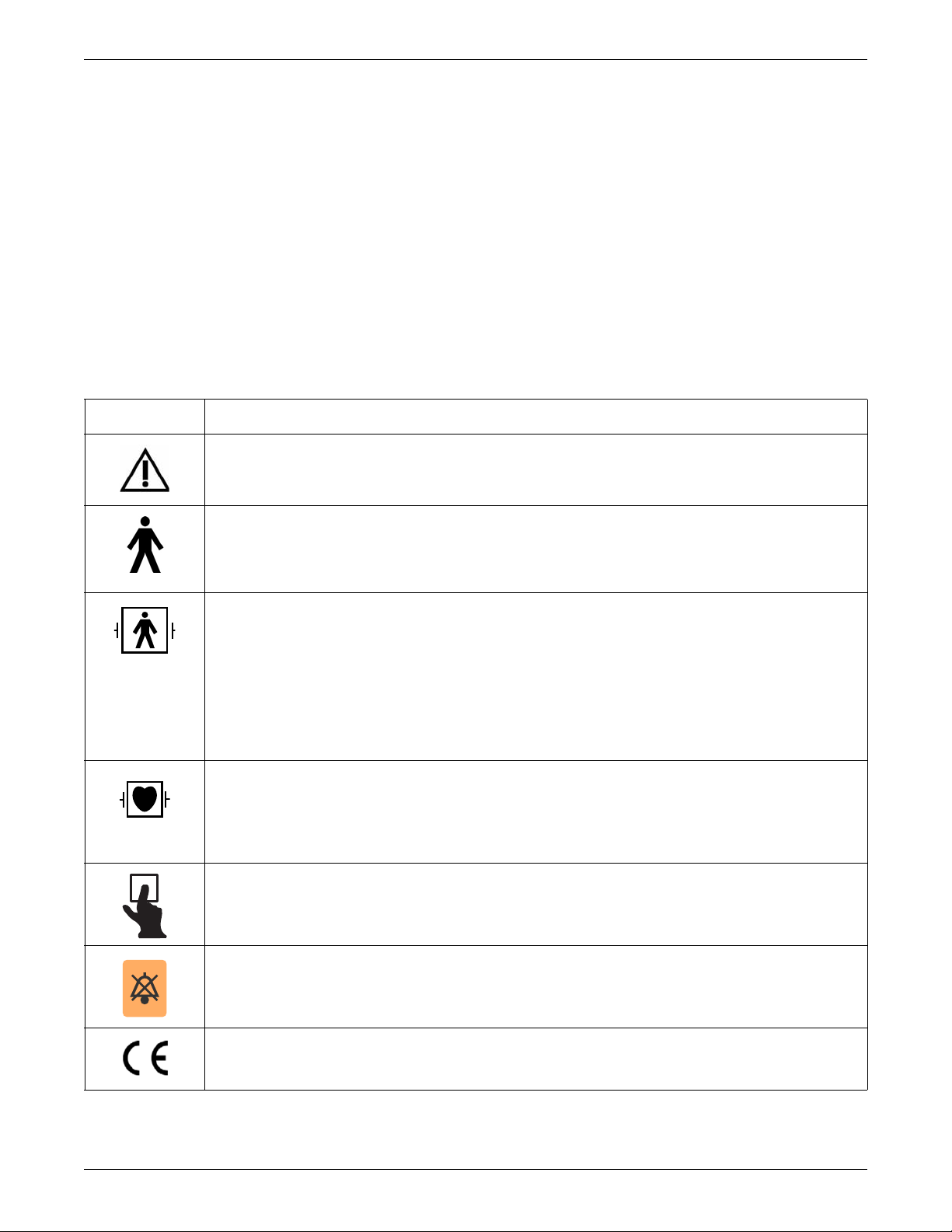
Equipment symbols
NOTE
Some symbols may not appear on all equipment.
Symbol Description
ATTENTION: Consult accompanying documents.
Introduction
TYPE B APPLIED PART: Non-isolated applied part suitable for intentional external and internal application to the
patient excluding direct cardiac application.
[Medical Standard Definition:] Applied part complying with the specified requirements of IEC 60601-1 Medical
Standards to provide protection against electric shock, particularly regarding allowable leakage current.
TYPE BF APPLIED PART: Isolated (floating) applied part suitable for intentional external and internal application to
the patient excluding direct cardiac application. “Paddles” outside the box indicate the applied part is defibrillator proof.
[Medical Standard Definition:] F-type applied part (floating/isolated) complying with the specified requirements of IEC
60601-1 Medical Standards to provide a higher degree of protection against electric shock than that provided by type
B applied parts.
NOTE
The rating of protection against electric shock (indicated by symbol for CF or BF) is achieved only when used
with patient applied parts recommended by GE.
TYPE CF APPLIED PART: Isolated (floating) applied part suitable for intentional external and internal application to
the patient including direct cardiac application. “Paddles” outside the box indicate the applied part is defibrillator proof.
[Medical Standard Definition:] F-type applied part (floating/isolated) complying with the specified requirements of IEC
60601-1 Medical Standards to provide a higher degree of protection against electric shock than that provided by type
BF applied parts.
Writer door button.
Silence Alarm keyboard key.
CE mark.
2026419-033E CIC Pro™ 1-9
Page 22
Introduction
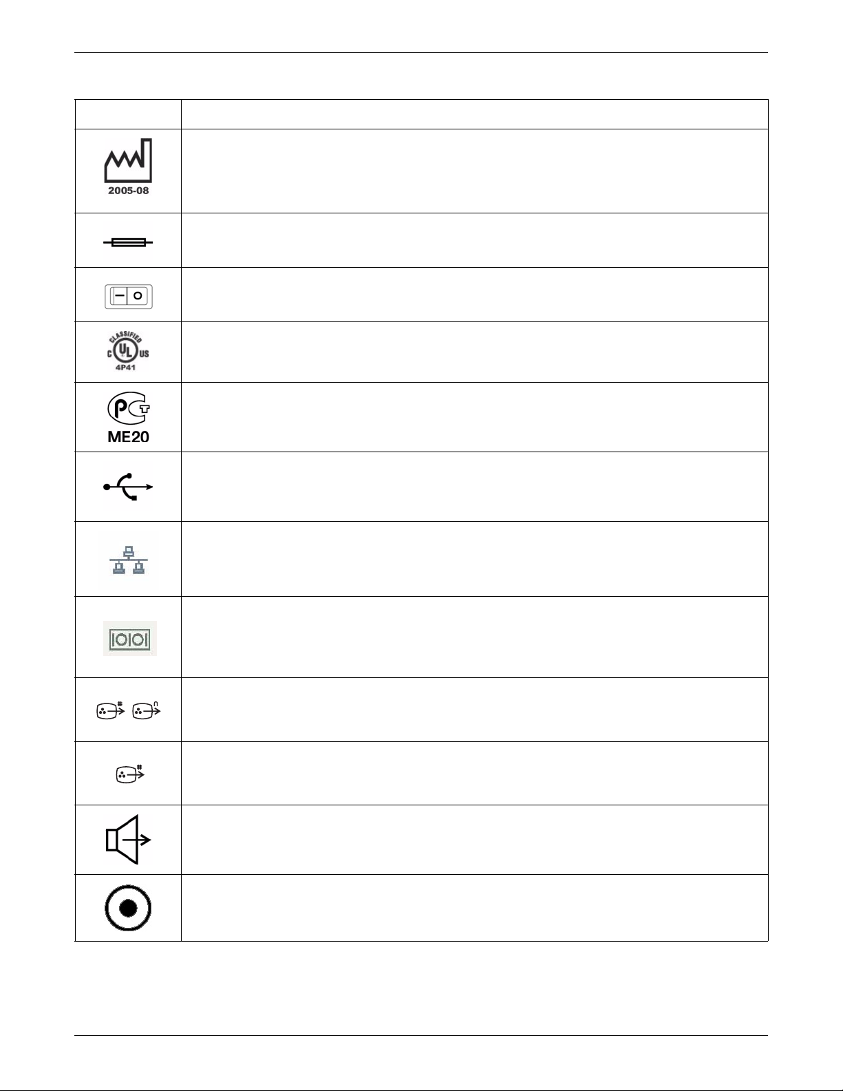
Symbol Description
This symbol indicates the date of manufacture of this device. The first four digits identify the year and the last two
digits identify the month.
Fuse. Replace the fuse with a fuse of the same type and rating.
Power On and Off.
Medical Equipment. With Respect to Electric Shock, Fire and Mechanical Hazards Only, In Accordance with UL
60601-1, CAN/CSA C22.2 NO.601.1, and IEC 60601-1.
For Russia only: Russian GOST-R certification.
USB connector port.
Ethernet connector port used to connect to the CARESCAPE Network (MC or IX network) as indicated on the device.
Serial connector ports 1 and 2.
Digital Visual Interface - Integrated for primary video connection that supports digital and analog displays.
Digital Visual Interface - Digital for secondary video connection that supports digital displays only.
Speaker out connector port.
Power indicator.
1-10 CIC Pro™ 2026419-033E
Page 23
Symbol Description
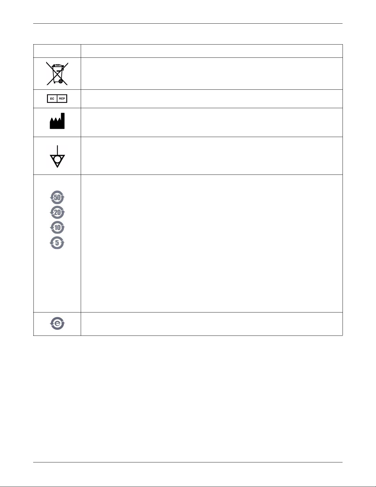
This symbol indicates that the waste of electrical and electronic equipment must not be disposed as unsorted
municipal waste and must be collected separately. Please contact the manufacturer or other authorized disposal
company to decommission your equipment.
European authorized representative.
Manufacturer name and address.
Equipotential stud. A ground wire from another device can be tied here to ensure the devices share a common
reference point.
NOTE
The following symbols (required by China law only) are representative of what you may see on your equipment.
Introduction
The number in the symbol indicates the EFUP period in years, as explained below. Check the symbol on your
equipment for its EFUP period.
This symbol indicates the product contains hazardous materials in excess of the limits established by the Chinese
standard SJ/T11363-2006 Requirements for Concentration Limits for Certain Hazardous Substances in Electronic
Information Products. The number in the symbol is the Environment-friendly User Period (EFUP), which indicates the
period during which the toxic or hazardous substances or elements contained in electronic information products will
not leak or mutate under normal operating conditions so that the use of such electronic information products will not
result in any severe environmental pollution, any bodily injury or damage to any assets. The unit of the period is
“Year”.
In order to maintain the declared EFUP, the product shall be operated normally according to the instructions and
environmental conditions as defined in the product manual, and periodic maintenance schedules specified in Product
Maintenance Procedures shall be followed strictly.
Consumables or certain parts may have their own label with an EFUP value less than the product. Periodic
replacement of those consumables or parts to maintain the declared EFUP shall be done in accordance with the
Product Maintenance Procedures. This product must not be disposed of as unsorted municipal waste, and must be
collected separately and handled properly after decommissioning.
This symbol indicates that this electronic information product does not contain any toxic or hazardous substance or
elements above the maximum concentration value established by the Chinese standard SJ/T1 1363-2006, and can be
recycled after being discarded, and should not be casually discarded.
Service requirements
Follow the service requirements listed below, and in the Preventive maintenance
chapter of this manual.
Refer equipment servicing to GE authorized service personnel only.
Any unauthorized attempt to repair equipment under warranty voids that
warranty.
It is the user’s responsibility to report the need for service to GE or to one of their
authorized agents.
2026419-033E CIC Pro™ 1-11
Page 24
Introduction
### ## ## #### # #
123456
Failure on the part of the responsible individual, hospital, or institution using this
equipment to implement a satisfactory maintenance schedule may cause undue
equipment failure and possible health hazards.
Regular maintenance, irrespective of usage, is essential to ensure that the
equipment is always functional when required.
Manufacturer responsibility
GE is responsible for the effects of safety, reliability, and performance only if:
Assembly operations, extensions, readjustments, modifications, or repairs are
carried out by persons authorized by GE;
The electrical installation of the relevant room complies with the requirements of
the appropriate regulations.
The equipment is used in accordance with the instructions for use.
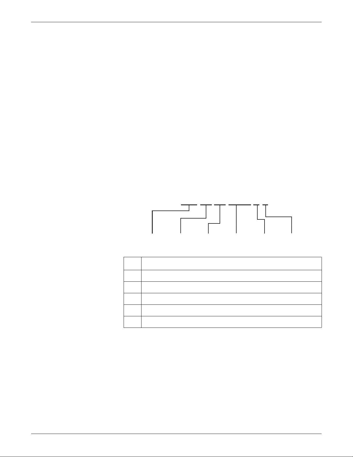
Equipment identification
Every GE device has a unique serial number for identification. A sample of the
information found on a serial number label is shown below.
1
Product code
1
2 Year manufactured
3 Fiscal week manufactured
4 Production sequence number
5 Manufacturing site
6 Miscellaneous characteristic
1
The product code is:
SDY for the MP100D (desktop model) platform
SDZ for the MP100R (rack-mounted mode l) plat form
1-12 CIC Pro™ 2026419-033E
Page 25

Manual information
Manual purpose
This manual supplies technical information for service representatives and technical
personnel so they can maintain the equipment to the assembly level. Use it as a guide
for maintenance and electrical repairs considered field repairable. Where necessary,
the manual identifies additional sources of relevant information and technical
assistance.
Intended audience
This manual is intended for use by service representatives and technical personnel
who maintain, troubleshoot, or repair the equipment.
Related manuals
Introduction
Conventions used
Equipment terms
Critical Care Monitoring Clinical Reference and Troubleshooting Guide
CIC Pro™ Clinical Information Center Operator’s Manual
CIC Pro™ Clinical Information Center Technical Specifications Supplement
MP100 Series
This manual uses the following terms to simplify common equipment names.
Term Description
MC network Refers to the CARESCAPE Network MC network.
IX network Refers to the CARESCAPE Network IX network.
CIC Pro center Refers to the CIC Pro Clinical Information Center.
CIC Pro Refers to the CIC Pro Clinical Information Center.
Flash drive Solid-state drive.
Telemetry Server Refers to the ApexPro Telemetry Server/Tower.
Transmitter/transceiver Refers to an Apex, ApexPro or ApexPro CH transmitter or
ApexPro FH transceiver.
USB memory stick A memory data storage device which is used to create an
image to restore the CIC Pro center software and to activate
CIC Pro center licenses.
Writer Refers to the PRN 50-M digital writer.
2026419-033E CIC Pro™ 1-13
Page 26

Introduction
Text styles
Illustrations and names
This manual uses the following text styles to identify hardware terms, software terms
and the correct way to enter data.
Style Definition
Bold Indicates hardware items, such as keys, labels or connectors.
Bold and italicized Indicates software items, such as menus, menu options or
screen text.
Italics Emphasizes a word.
> Indicates menu options or control settings to select
consecutively.
+ Indicates keyboard keys to select simultaneously.
In this manual, all illustrations are provided as examples only. They may not
necessarily reflect your monitoring setup or data viewed on your monitoring device.
Ordering manuals
Revision history
All names appearing in examples and illustrations are fictitious. The use of any real
person’s name is purely coincidental.
A paper copy of this manual will be provided upon request. Contact your local GE
representative and request the part number on the first page of the manual.
Each page of this document has the document part number and revision letter at the
bottom of the page. The revision letter changes whenever the document is updated.
Revision Comments
A Release of CIC Pro v5.1.
B Updated Warnings and the Set up a mirror CIC Pro center
section.
C Updated for Log Compression Configuration Utility.
D Updated for new printer.
E Updated the section on configuring the NO COMM alarm
setting.
1-14 CIC Pro™ 2026419-033E
Page 27

2
Equipment overview
2026419-033E CIC Pro™ 2-1
Page 28
Equipment overview
1
2
3
4
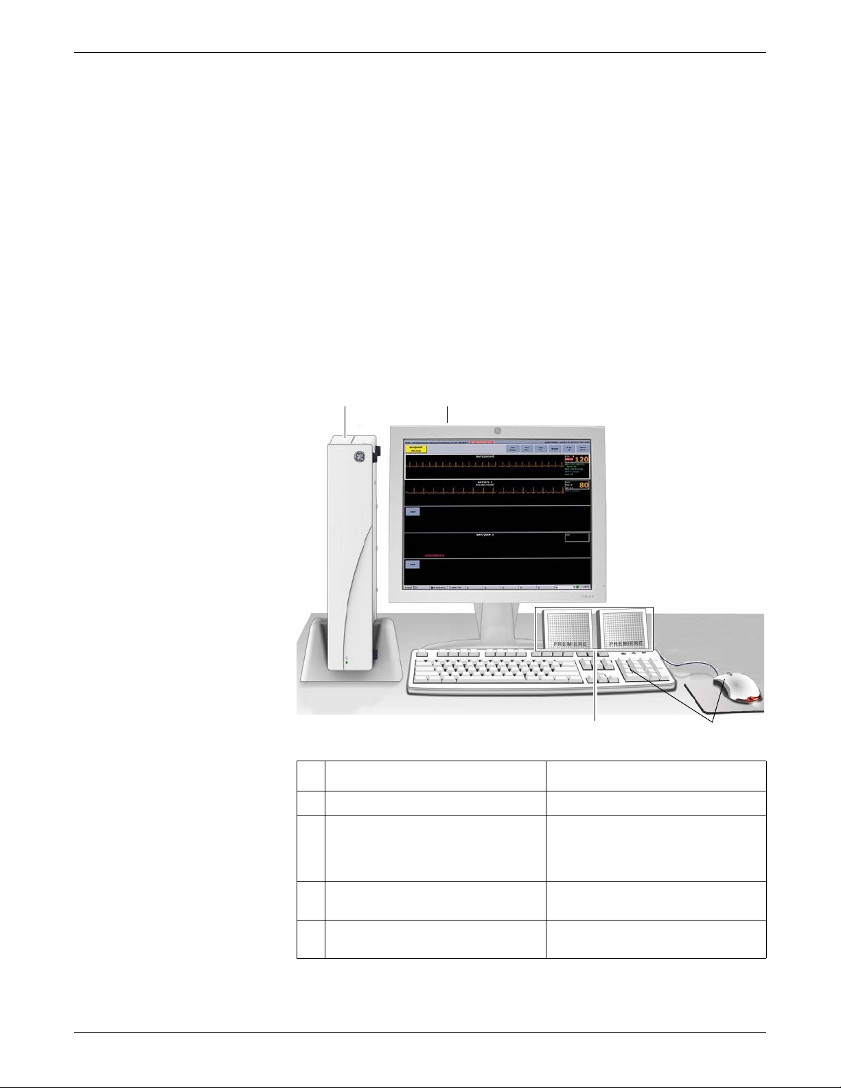
Standard components
NOTE
The Unity Network has been renamed to the CARESCAPE Network. Not all
references to the Unity Network will be changed immediately; Unity may appear
in some places and CARESCAPE in others. It is important to understand that
while the CARESCAPE Network replaces the Unity Network name, they refer to
the same GE monitoring network
Standard components include the following items:
Processor box
Primary display
External speakers
Standard keyboard and mouse
2-2 CIC Pro™ 2026419-033E
Item Function
1 Processor box Run the CIC Pro center application.
2 Primary display Display real-time and stored patient data,
control windows, and various system level
operations. Can display 16 patients
simultaneously.
3 Standard mouse and keyboard Enter data, navigate menus, and choose
options.
4 External speakers Sound audible patient status and system
status alarm tones.
022B
Page 29

Display
14
Front view
1 2
3 4
5
6
7
9
8
10
11
12
13
Back view
18
Processor box
Desktop views
Equipment overview
You can configure the CIC Pro center to display real-time parameter waveforms and
numeric data for one to 16 patients. See Set the Display Configuration (non-mirror
CIC Pro centers) on page 6-49.
You can also view stored parameter waveforms and numeric data, control windows,
and various system level operations.
The processor box runs the CIC Pro center application. It can be ordered as a desktop
server (MP100D) or as a rack-mounted server (MP100R) and has the following
connectors, ports, and switches. For information on USB extender limitations, see
Restrictions on page 5-11.
2026419-033E CIC Pro™ 2-3
Page 30
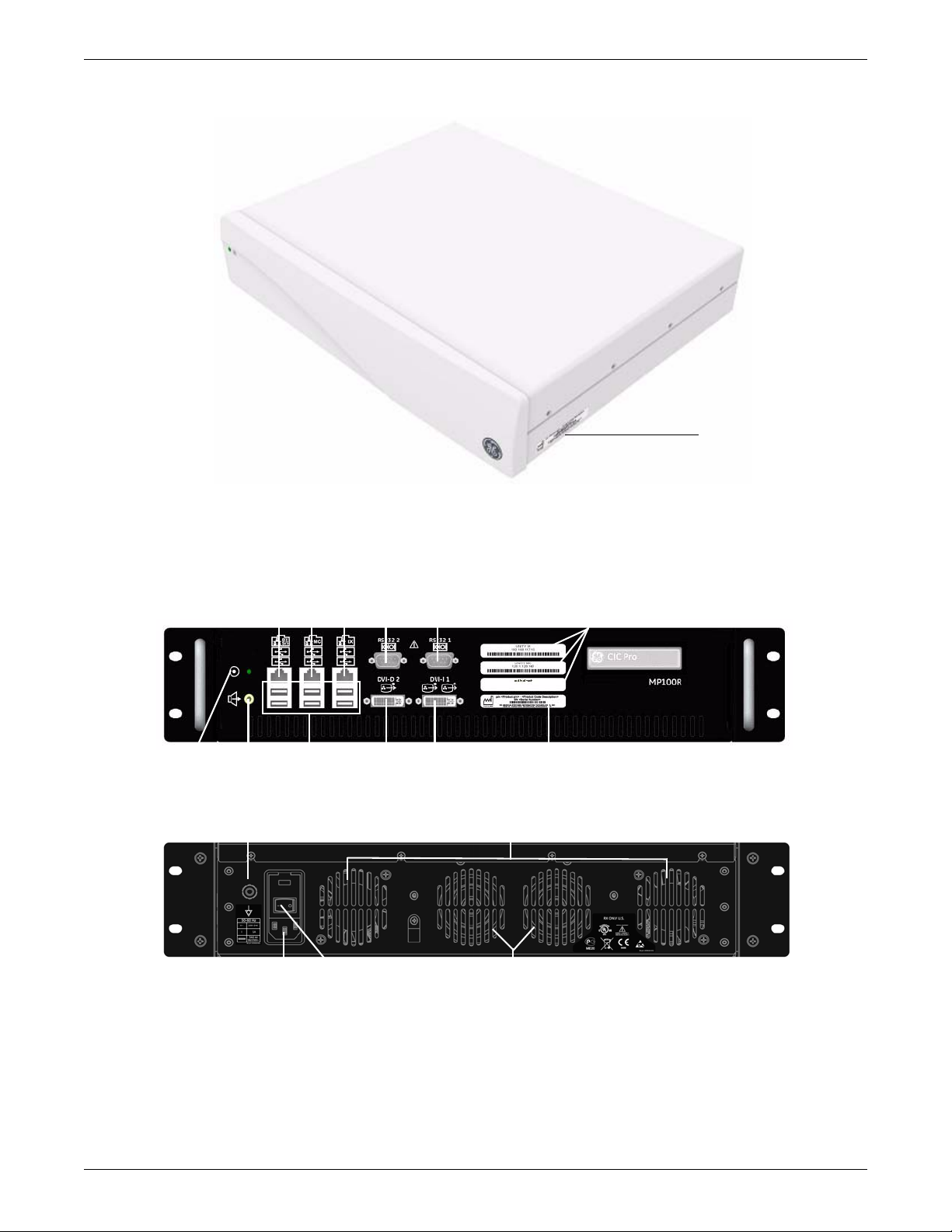
Equipment overview
16
Side view
3 4
5
6
7
8
9
10
11
14
Front view
16
17
1
2
12
13
15
Back view
Rack-mount views
2-4 CIC Pro™ 2026419-033E
Page 31

Connectors, ports and switches
Item Function
Equipment overview
1 Equipotential stud Connect a ground wire from another device to ensure the devices share a common reference
2 Ventilation opening Vent internal processor heat to the outside of the processor box.
3RX
S/5
4 CARESCAPE Network MC
network connection
5 CARESCAPE Network IX
network connection
6 RS232 2 connector Connect to the PRN 50-M digital writer.
7 RS232 1 connector Connect to the serial touchscreen display.
8 DVI-I 1 video connector Connect to the primary display.
9 DVI-D 2 video connector Connect to an optional secondary display.
10 USB ports There are six USB ports you can use to connect the following devices:
point.
Do not use this port or connect to any device. This port is physically disabled by a dummy plug.
Interface with other networked GE patient monitoring and telemetry system devices.
Display waveform, parameter, and alarm condition data from other networked devices.
Provide ability to display full disclosure data.
Access remote serviceability.
Connect to an optional network laser printer.
Connect to an optional Citrix server.
Connect to an optional web browser.
Standard mouse.
Standard keyboard.
Touchscreen display.
USB memory stick (used to activate CIC Pro center licenses and other servicing functions).
USB printers.
11 External speaker connector Connect to external speakers to hear patient and system status alarm notification.
12 Power switch Press to turn on or to turn off.
13 Power connector Connect the power cable.
14 Power indicator Illuminates when powered on.
15 Speaker opening Permits internal speaker to sound externally.
16 IP address labels Identifies the IP address of this device on the respective networks.
NOTE
The CIC application does not use the S/5 network,
17 Serial number label Identifies the serial number of the device.
18 Power clamp Provided to clamp the power cord and speaker.
2026419-033E CIC Pro™ 2-5
Page 32

Equipment overview
Controls
Mouse
Use a standard mouse to select menu options or patient data.
Mouse pointer shapes
Depending on the operation mode of the CIC Pro center, the mouse pointer changes
its appearance.
Pointer Function
Arrow: Indicates the CIC Pro center is operating in user mode.
Use the arrow pointer to select menu options, patient data, and to
navigate from window to window.
I-beam: Indicates the pointer is in a data entry field.
Enter text when this pointer is displayed.
Cross: Indicates the CIC Pro center is operating in Service mode.
CAUTION
QUALIFIED PERSONNEL — The Service mode is intended for use
only by qualified personnel with training and experience in its use.
The consequences of misuse include loss of alarm configuration, loss
of patient data, corruption of the CIC Pro center’s operating system
software, or disruption of the CARESCAPE Network.
Using the MultiKM application
If the MultiKM license is activated, you may use one keyboard and one mouse across
multiple CIC Pro centers that are centralized and configured in the same keyboard
and mouse group. When the MultiKM icon appears in the lower right corner of the
display screen, the MultiKM license is activated on this CIC Pro center.
With the MultiKM license activated, you can do the following tasks:
Move the mouse across all CIC Pro centers in the group.
Access any CIC Pro center’s display screen or enter text into any of the CIC Pro
center’s text fields in the group.
Support right and left mouse clicks and scroll wheel movement.
For more information, see Perform MultiKM (Multimouse) setup on page 6-77.
2-6 CIC Pro™ 2026419-033E
Page 33

Keyboard
Equipment overview
Use a standard keyboard to type text into a data entry field.
NOTE
When using the MultiKM software application, you may use one keyboard and
one mouse across multiple centralized CIC Pro centers.
Typing text into a data entry field
To type text into a data entry field, position the mouse pointer over the data entry
field. When the mouse pointer changes to an I-beam, click the left mouse button and
begin typing.
Silence Alarms keyboard key
This icon label is affixed on the Pause Break key.
NOTE
If the MultiKM license is activated, you must position the mouse cursor in the
patient window of the CIC Pro center where the alarm condition is occurring.
Then press the Silence Alarms keyboard key to silence all alarms on this CIC
Pro center for one minute.
Press the Silence Alarms key, to silence all alarms for one minute. Alarms that are in
queue to sound are also silenced. Any new patient alarm condition cancels the alarm
silence, breaking through to sound the new alarm.
Power indicator
The power indicator is located on the front left side of the CIC Pro center processor
box. The power indicator illuminates green when the power is turned on.
Optional components
Optional components include the following items:
Secondary display on page 2-8
Touchscreen displays on page 2-9
Laser printer on page 2-9
PRN 50-M digital writer on page 2-10
Un-interruptible power supply (UPS) on page 2-11
2026419-033E CIC Pro™ 2-7
Page 34

Equipment overview
Secondary display
The secondary display supports patient data review functions and can be configured
to display CIC Pro center applications in full screen or half screen formats. Using a
secondary display provides more room for real-time patient monitoring in the primary
display.
From a secondary display, you can do the following:
View all of the single patient viewer applications.
View two single applications at the top and bottom half of the screen.
View all applications (excluding multi-patient viewer) in this secondary display.
View web and Citrix (if enabled) applications.
Navigate between applications via the enhanced software tools provided.
Access custom views of routine applications using a single mouse click.
The following requirements apply when using a secondary display with your CIC Pro
center:
Secondary displays must be the same type and the same size as the primary
display. For a list of displays that are validated for use with the v5.1.x CIC Pro
center, refer to Touchscreen display video drivers on page 6-32.
Secondary displays and primary displays must be set to the same 1280 x 1024
display resolution. No other display resolutions have been validated for use with
the v5.1.x CIC Pro center.
Secondary displays will not function until you have first completed the following
tasks:
Activated the required licenses.
Restarted the CIC Pro center.
To configure the secondary display, see Configure a secondary display on page 6-30.
2-8 CIC Pro™ 2026419-033E
Page 35

Touchscreen displays
Mirror display
Equipment overview
The touchscreen display allows you to select any selectable screen object by gently
tapping the object with your finger.
The following guidelines apply when using a touchscreen display:
Applying tape or other items to the screen impairs the touchscreen’s
functionality.
Using pencils, pens, or other sharp, pointed objects can damage the touchscreen.
Displaying right click menus is not supported by the touchscreen.
Primary and secondary displays can be a combination of touchscreen and non-
touchscreen displays.
Networked remote displays can pr ov ide a duplicate (mirror image) vi ew of a pri mary
CIC Pro center. When external speakers are connected to the remote displays, audible
alarm tones can also be sounded.
Laser printer
WARNING
SHOCK HAZARD — Laser printers are UL 60950/IEC 60950
certified equipment, which may not meet the leakage current
requirements of patient care equipment. This equipment must not be
located in the patient environment unless the medical system
standard IEC 60601-1-1 is followed.
Do not connect a laser printer to a multiple portable socket outlet
(MPSO) supplying patient care equipment. The use of an MPSO for
a system will result in an enclosure leakage current equal to the sum
of all the individual earth leakage currents of the system if there is
an interruption of the MPSO protective earth conductor.
The supported printers include:
HP LaserJet 2430 (USB and Network)
HP LaserJet P3005 (USB and Network)
HP LaserJet P3015 (USB and Network)
HP LaserJet 4000 (Network only)
HP LaserJet 4050 (Network only)
HP LaserJet 4100 (Network only)
HP LaserJet 4200 (Network only)
HP LaserJet 4250 (Network only)
A laser printer can be configured to print alarm graphs, control settings, waveforms,
parameter numeric data, events, full disclosure, and graphic trend data.
2026419-033E CIC Pro™ 2-9
Page 36

Equipment overview
2
3
4
56
1
98
7
NOTE
PRN 50-M digital writer
A PRN 50-M digital writer can be connected to the CIC Pro center to print alarm
graphs, control settings, waveforms, events, and trend data. The writer prints reports
and graphs on 2-inch wide paper.
The following controls, indicators, and connectors are located on the front and back
of the digital writer.
Consult your sales representative or Technical Support for the latest supported
printers.
030A
PRN 50-M digital writer: Front and back views
Item Function
1 Writer door button Press to open the door and replace the writer paper.
2 Graph stop button Press to stop printing a graph. Holding the button will generate a
3 Paper out indicator Illuminates when you need to replace the paper. See Change
4 Power indicator Illuminates when the writer is connected to a power source.
5 Power switch Press to turn on or turn off the writer.
6 Power connector Connect the writer’s power cable.
7 Power cable clamp Connect to the writer’s power cable. This prevents the cable
8 M-port connector Connect to the CIC Pro center.
9 ASYNC COMM port Not used. This port may not be present on some models.
self-test print.
writer paper on page 5-17.
from being pulled out of the power connector.
2-10 CIC Pro™ 2026419-033E
Page 37

Un-interruptible power supply (UPS)
WARNING
LOSS OF MONITORING — If power to the CIC Pro center is lost,
patient monitoring information will no longer be displayed or stored.
GE recommends using an un-interruptible power supply with the CIC Pro center.
Without a UPS, power line outages may result in:
Improper shutdown of the CIC Pro center, causing lengthy disk scan procedures
on reboot.
Data loss.
Failure of the CIC Pro center and other hardware components.
Theory of operation
Equipment overview
Functional description
The CIC Pro center application is designed to provide real-time patient data and
alarms for central nurse stations in hospitals. It can display real-time waveforms and
vital sign data, with visual and audible alarms, for up to 16 patients simultaneously.
The CIC Pro center supports both wired and wireless monitors and telemetry data.
The CIC Pro center software allows users to select any bed on the CARESCAPE
Network MC network and display an expanded view of that bed’s real-time
parameters and waveforms. This expanded view also allows users to view and modify
settings within the care unit, and view a patient’s other data (including alarm histories,
graphic trends and tabular trends).
The user can configure the number of patients displayed by the system, and the
number of displayed waveforms per patient. Waveform colors are also configurable.
All configuration data is stored, and is restored after a system power cycle or software
restart.
2026419-033E CIC Pro™ 2-11
Page 38

Equipment overview
FLASH
DRIVE
Block diagram
Physiological data
Periodic data
Episodic data
CIC Pro centers trend two types of physiological data: periodic and episodic.
Periodic data is constantly updated. Data is sampled every two seconds to yield 30
samples per minute. The displayed value is the median of the 30 samples. It is always
the median of a one-minute time frame, regardless of the interval selected.
The interval is the time between values, not the time of the value itself. For example,
a five-minute interval means one-minute samples spaced five minutes apart, not fiveminute samples, and not a median of the five one-minute samples. Odd number
values are rounded down to the nearest even number.
If the calibration of the system clock changes (for example, daylight saving time), the
time for periodic data slides into the revised time. However, episodic data is timestamped and retains its original time.
Examples of periodic data include heart rate and invasive blood pressure.
Episodic data is parameter data that is user, or system, generated. An example of
episodic data is non-invasive blood pressure.
2-12 CIC Pro™ 2026419-033E
Page 39

File and data management
Log files
Log files generated by the CIC Pro center application, other associated applications,
and the CIC Pro center operating system are used during system analysis, problem
diagnosis, and troubleshooting. See Access log files on page 10-14 for more
information.
RWHAT packets
All monitoring devices on the CARESCAPE Network periodically broadcast
information about themselves in “RWHAT” packets. Among other things, RWHAT
packets contain IP address, port number, name, and offered services information
about each device.
All monitoring devices listen for RWHAT packets, and maintain a database of
information about other devices on the network. When devices need to communicate,
the appropriate IP address information is obtained from the database, CARESCAPE
Network-protocol messages are created, and operating system services are used to
transmit the message on the network.
Equipment overview
Storage
Printing
For example, when a CIC Pro center computer communicates with a telemetry
device, the telemetry device’s IP address is retrieved from the CIC Pro center
computer RWHAT database, the CARESCAPE Network messages are created, and
the CIC Pro center Windows operating system sends the messages to the telemetry
device.
The Full Disclosure (FD) Data interface uses the CARESCAPE Network IX
network to retrieve data from the database.
Each bed is stored in a separate directory, containing one index file and many
record files.
The FD Page printout is a configurable, time-period (license dependent)
overview of waveform activity. It is activated by clicking the print button located
in the top right corner of the FD Page window.
The FD Strip printout is a quick snapshot of what is currently on the screen. It is
activated by clicking the print button while the FD Page is being viewed.
There is a separate full disclosure printer selection from the main laser printer
selection on the setup page. Specifying a printer here does not advertise this CIC
Pro center as a print server on RWHAT (like the main laser selection). It is used
exclusively by the local full disclosure system. A printer must be “Added” to the
operating system before it will show up in the drop-down list.
2026419-033E CIC Pro™ 2-13
Page 40

Equipment overview
Licensing
Full disclosure
All features and functions of the CIC Pro center are determined by the licenses
activated and running on each CIC Pro center. Licenses are specific to each individual
CIC Pro center’s serial number, are node locked, and cannot be used (floated) by
another CIC Pro center.
The CIC Pro center full disclosure system stores all waveform and parametric data
from a patient for up to 72 hours. This data can be randomly accessed later in a static
display that looks similar to the real-time display window. To accomplish this, every
CARESCAPE Network waveform packet (4/sec) and every parameter packet (1
every 2 seconds) is stored on the CIC Pro center. In addition, one RWHAT packet and
one admit packet is stored every minute to help recreate the patient’s history.
Unlike an alarm history event stored at the bedside, which only stores a 10 second
snap shot surrounding the event, full disclosure allows the user to scroll back in time
(prior to the event and leading up to the event).
Behaviors or rules
Installation
Incompatible with previous full disclosure system (prior to CIC Pro center v3.x).
Certain Unit Defaults are incompatible with CIC Pro center v3.x systems.
Start-up modes
Mode Description
Auto For All Automatically detects admitted beds that are not currently storing
full disclosure data anywhere and attempts to start full disclosure on
one of the CIC Pro centers within the care unit. This works
regardless of whether the bed was admitted directly at the bedside
or the CIC Pro center. Full disclosure cannot be stopped on a
particular bed until the bed is discharged.
Auto If Listed Same as Auto For All, but only if the bed in question is entered into
the list on the FD Unit Defaults setup screen. All other beds are not
storing full disclosure data.
Manual Mode Beds are not automatically storing full disclosure data upon
admission. Users can manually start and stop full disclosure for a
particular bed by using a button located on the FD Strip page in the
single viewer window. All full disclosure data is deleted when full
disclosure is stopped for a bed. See the CIC Pro Clinical
Information Center Operator’s Manual for more information.
Licensing
Support for up to 16 patients per CIC Pro center.
2-14 CIC Pro™ 2026419-033E
Page 41

Control
Equipment overview
Stores 72 hours of data per patient regardless of license type. Licensing controls
amount of data that is viewable.
Unit Licensing Mode sets which type of license is requested. Supported types:
None (default - 1 hour), 24, 48, 72 hours.
Failure to obtain a license results in no patient data is stored for full disclosure.
Licensing information is stored with data, so restrictions follow data regardless
of where it is viewed, even if viewed in a different care unit with a different Unit
License Mode.
CIC Pro center master and full disclosure
There is one full disclosure master CIC Pro center per care unit. The CIC Pro center
with the lowest MC IP address (126.x.x.x is “lower” than 3.x.x.x) within the care unit
becomes the full disclosure master.
The CIC Pro center master performs the following activities in one minute
increments:
Detects admitted (but not full disclosure data collection) beds within the care
unit, for Auto modes.
Assigns beds (for full disclosure acquisition) to CIC Pro centers within the care
unit.
Applies multi-full disclosure, twin-bed rules, and rover rule.
Identifies CIC Pro centers with full disclosure capability.
NOTE
The CIC Pro center master checks the software versions of the other CIC Pro
centers before trying to identify CIC Pro centers with full disclosure
capability . Software versions earlier than 2.5 are ignored.
Guarantees that the right CIC Pro center is contacted if retrieving data while a
multi-full disclosure condition is occurring and that the multi-full disclosure
condition will be corrected.
NOTE
A CIC Pro center will not act as full disclosure master during the first minute
after it starts up. Instead, the latest data is first collected from the other CIC
Pro centers on the network, and this data determines which CIC Pro center
becomes master. Multiple masters on a network might occur, but only briefly
(this will self-correct within a couple of minutes).
Minute rule or the Offline Storage setting
For more information, see Set the full disclosure defaults on page 6-47.
The Offline Storage setting determines the length of time the CIC Pro center will
maintain full disclosure data for a bed from which it has stopped receiving data (e.g.,
a NO COMM condition).
If the NO COMM condition ends within the Offline Storage setting time frame,
full disclosure data collection for the bed continues.
2026419-033E CIC Pro™ 2-15
Page 42

Equipment overview
If a NO COMM condition exceeds the Offline Storage setting time frame, all
data for the bed is deleted. If (while in Auto mode) the bed comes back online
(the NO COMM condition ends) after this point, the bed is reassigned as a new
and different bed and new data collection is started for the bed.
When a CIC Pro center starts up, it determines when full disclosure data was last
received from the assigned beds.
If the latest data for a bed:
Is not older than the Offline Storage setting, then full disclosure data
collection continues for the bed.
Is older than the Offline Storage setting, existing data associated with the
bed is deleted, and new data collection is started for the bed.
Multi-full disclosure rule
If multiple CIC Pro centers are running in a care unit, the multi-full disclosure rule
allows the switching of full disclosure data collection from one CIC Pro center to
another, if a CIC Pro center goes offline (e.g., reboot, shutdown, etc.).
The following examples describe how the multi-full disclosure rule works when using
two CIC Pro centers (CICA and CICB).
NOTE
In the examples, start up mode is Auto, and only one bed (BED1) is used.
Example 1:
1. CICA goes offline and stops full disclosure data collection on BED1. This causes
CICB to begin full disclosure data collection on BED1.
NOTE
The master CIC Pro center detects CICA going offline, and switches full
disclosure data collection over to CICB, within a minute of the offline event
occurring.
2. CICA comes back online withi n the Offline Storage setting time frame, and
continues full disclosure data collection on BED1 again. At this point, CICA and
CICB are both collecting full disclosure data on BED1.
3. The multi-full disclosure rule does not allow more than one CIC Pro center to
collect full disclosure data from the same bed at the same time--only the data that
goes the farthest back in time (CICA) is kept. Because of this, CICA continues
collecting full disclosure data on BED1, and CICB stops.
2-16 CIC Pro™ 2026419-033E
Page 43

Equipment overview
Example 2:
1. CICA goes offline and stops collecting full disclosure data on BED1. This causes
CICB to begin collecting full disclosure data on BED1.
NOTE
The master CIC Pro center detects CICA going offline, and switches full
disclosure data collection over to CICB, within a minute of the offline event.
2. CICA comes back online after exceeding the Offline Storage setting time frame.
Because of this, existing BED1 data is deleted from CICA, and the new BED1
data collection begins on CICA. At this point, CICA and CICB are BOTH
collecting full disclosure data on BED1.
3. The multi-full disclosure rule does not allow more than one CIC Pro center to
collect full disclosure data from the same bed at the same time (only the data that
goes the farthest back in time (CICB) is kept). Because of this, CICB continues
collecting full disclosure data from BED1, and CICA stops.
NOTE
At every wake-up cycle (1 minute interval), the CIC Pro center full
disclosure master scans all CIC Pro centers within the care unit to determine
if more than one CIC Pro center is collecting full disclosure data from the
same bed (this can happen as part of normal operation). If the master detects
this condition, all CIC Pro centers are instructed to stop collecting full
disclosure data from the bed except for the one CIC Pro center with the
oldest data for the bed.
Combo mode (twin-bed rule)
In Combo mode:
1. Two beds are on the network: one is a hardwired/bedside monitored bed, and the
other is telemetry bed. Both beds share the same name (e.g. BED), but '*' is
appended to the telemetry bed name (e.g. BED and BED*). Both beds represent
the same patient.
NOTE
If the hardwire or telemetry bed was not functioning in Combo mode, these
two beds would be treated as distinct and separate.
2. Only the oldest bed data is kept. Data for the other bed is deleted.
3. No matter which data is kept, full disclosure data collection continues, and the
data is stored under the bed name, but without the '*'.
2026419-033E CIC Pro™ 2-17
Page 44

Equipment overview
NOTE
Combo mode is stopped (breaking Combo mode) by discharging either bed.
If this happens, full disclosure data collection continues on the undischarged
bed, and the data is stored under the undischarged bed name.
NOTE
If the hardwired bed is discharged, '*' would again be included in the name.
The following are Combo mode examples:
Combo mode Example 1:
1. A hardwired bed BED is admitted and full disclosure data is collected.
2. A telemetry bed BED* is admitted and full disclosure data is collected. Two
separate full disclosure data stores exist, one for each bed (possibly on a different
CIC Pro centers).
3. The two beds are put into Combo mode. When this happens, BED data is kept
because it is older than BED* data, and BED* data is deleted. Full disclosure
data collection continues, and the data is stored under the name BED.
4. Combo mode is broken by discharging BED*. Full disclosure data collection
continues, with the data still stored under the name BED.
Combo mode Example 2:
1. A hardwired bed BED is admitted and full disclosure data is collected.
2. A telemetry bed BED* is admitted and full disclosure data is collected. Two
separate full disclosure data stores exist, one for each bed (possibly on a different
CIC Pro centers).
3. The two beds are put into Combo mode. When this happens, BED data is kept
because it is older than BED* data, and BED* data is deleted. Full disclosure
data collection continues, and the data is stored under the name BED.
4. Combo mode is broken by discharging BED. Full disclosure data collection
continues, and the data is now stored under the name BED*.
2-18 CIC Pro™ 2026419-033E
Page 45

Equipment overview
Combo mode Example 3:
1. A telemetry bed BED* is admitted and full disclosure data is collected.
2. A hardwire bed BED is admitted and full disclosure data is collected. Two
separate full disclosure data stores exist, one for each bed (possibly on a different
CIC Pro centers).
3. The two beds are put into Combo mode. When this happens, BED* data is kept
because it is older than BED data, and BED data is deleted. Full disclosure data
collection continues, and the data is stored under the name BED.
4. Combo mode is broken by discharging BED*. Full disclosure data collection
continues, and the data is still stored under the name BED.
Combo mode Example 4:
1. A telemetry bed BED* is admitted and full disclosure data is collected.
2. A hardwired bed BED is admitted and full disclosure data is collected. Two
separate full disclosure data stores exist, one for each bed (possibly on a different
CIC Pro center).
3. The two beds are put into Combo mode. When this happens, BED* data is kept
because it is older than BED data, and BED data is deleted. Full disclosure data
collection continues, and the data is stored under the name BED.
4. Combo mode is broken by discharging BED. Full disclosure data collection
continues, and the data is now stored under the name BED*.
Bed name/IP address changes (rover rule)
The CIC Pro center tracks full disclosure data for individual beds using a combination
of the bed name and IP address.
If a bed name changes during full disclosure data collection, information within the
data reflects the new name at the point the name change occurred.
If a bed IP address changes during full disclosure data collection, but the name does
not, it is interpreted as a new and different bed, and a new full disclosure data store is
created and utilized for the new bed.
2026419-033E CIC Pro™ 2-19
Page 46

Equipment overview
Unit Boundary
If a bed goes offline, and another bed with the same name but a different IP address
comes online, it is interpreted as a new and different bed and a full disclosure data
store is created and utilized for it. However, the following conditions apply:
If the bed that went offline (with the original IP address) comes back online
within the Offline Storage setting time frame, the two beds continue to be treated
as separate, since the different IP addresses positively identify them as distinct
and separate.
If the bed that went offline (with the original IP address) does not come back
online within the Offline Storage setting time frame, the bed with the new IP
address is interpreted as a replacement for the bed with the original IP address. In
this case, the full disclosure data for the bed with the original IP address is
deleted, and full disclosure data collection continues, and the data is stored under
the bed with the new IP address only.
Each care unit operates independently with respect to storage of full disclosure
data. The only interaction is when displaying data across care units.
License mode: All beds within a care unit will have access to the same amount of
data storage (based on time) unless there is a failure to get a license (1 hour).
NOTE
This can be different across different care units (e.g., UnitA-72hours, UnitB-
None (1 hour).
Networking
Start-up mode: The same start-up rules apply to all beds within a care unit.
Default: The same full disclosure defaults are used on all CIC Pro centers within
a care unit.
Full disclosure master: One per care unit.
Acquisition/storage: The master CIC Pro center will only assign beds within the
care unit to CIC Pro centers within that care unit. At no time will data for a bed
be stored on a CIC Pro center in a different care unit.
Bed unit changes: If a bed changes its care unit name during full disclosure data
collection, all data for the bed is deleted. The care unit where the bed moved
becomes responsible for the bed.
CIC Pro center unit changes: If a CIC Pro center changes its care unit name
during full disclosure data collection, all data for all beds being having full
disclosure data collected by that CIC Pro center is deleted. The care unit with the
original name is responsible for the beds.
NOTE
The Unity Network has been renamed to the CARESCAPE Network. Not all
references to the Unity Network will be changed immediately; Unity may appear
in some places and CARESCAPE in others. It is important to understand that
while the CARESCAPE Network replaces the Unity Network name, they refer to
the same GE monitoring network.
2-20 CIC Pro™ 2026419-033E
Page 47

Patient monitoring network
The CIC Pro center processes and displays real-time data acquired from up to 16
networked GE monitors or telemetry transmitters/transceivers connected to the
CARESCAPE Network.
When patient data is acquired from ApexPro telem etry transmitters/transceivers
(telemetry beds), the data is transmitted to a telemetry receiver where it is then
transferred to the CARESCAPE Network via a wired connection. The CIC Pro center
displays this telemetry bed patient data along with the patient data acquired from
other monitors.
Web access server network
WARNING
INTERNET EXPLORER FAVORITES — Saving Internet Explorer
Favorites (bookmarks) for web pages containing patient data is not
recommended. Doing so may result in patient data displayed in
Internet Explorer not matching the patient’s medical number.
Equipment overview
CITRIX Intranet web portal
CAUTION
SECURITY — The healthcare institution is responsible for ensuring
the privacy of any protected health information that is displayed on
this device.
CAUTION
SECURITY — The web browser which runs in conjunction with the
CIC Pro center is intended for hospital intranet use only. If
confidential patient information is made available from the hospital
intranet, the security of the data is the responsibility of the hospital.
The CIC Pro center can provide access to a Citrix client or an intranet browser for
viewing other applications (e.g., the hospital information system) or other sources of
patient data (e.g., labs, images, or MUSE™ Cardiology Information System data).
Access to a Citrix server or intranet server depends upon how your CIC Pro center is
configured and your on-site information technology offerings.
See Set up a Citrix client on page 6-19.
2026419-033E CIC Pro™ 2-21
Page 48

Equipment overview
Web browser intranet web portal
The CIC Pro center can provide a web portal to access and view other in-hospital web
applications or other sources of patient data. This web browser option is located in the
menu bar of the CIC Pro center display screen. Select this button to start a separate
Microsoft Internet Explorer application.
WARNING
LOSS OF MONITORING — If the browser funct i o n is
inappropriately used, loss of monitoring function may result. Use
alternate monitoring devices or close patient observation until the
monitoring function at the CIC Pro center is restored.
When using the browser, follow these restrictions:
Do not attempt to access the file systems of the CIC Pro center
through the use of the browser.
Do not attempt to download files of any type. This includes, but
is not limited to, audio or video files.
See Browser configuration on page 6-57.
Patient data interface
The CIC Pro center allows you to view patient data using two different viewers,
varying in data granularity:
Multi-patient viewer
Single patient viewer
Multi-patient viewer
The multi-patient viewer displays a snapshot of real-time waveform data and
parameter numeric data for a maximum of 16 patients.
The following picture identifies different areas of the multi-patient viewer.
2-22 CIC Pro™ 2026419-033E
Page 49

Equipment overview
1
2
3
4
5
6
7
8
9
Item Description
1 Alarm buttons. Show the care unit name, bed number, and the cause of the alarm.
2 Colored border alarm indicator. The patient window is outlined in red or yellow to
3 Alarm message.
4 Multi-patient viewer menu bar buttons. See the CIC Pro Clinical Information Center
5 Additional parameter information.
6 Patient name and Unit Name/Bed Name.
7 Real-time trend window.
identify a patient alarm condition. The alarm message is also displayed.
Operator’s Manuals for details.
The source of a patient’s parameter data can be from a monitor, a telemetry
transmitter/transceiver, or from both a monitor and a telemetry transmitter/
transceiver. To prevent the duplication of bed names and to help you identify the
parameter data source, the CIC Pro center appends the following symbols to the bed
name:
no symbol identifies a monitor (e.g., Unit Name/Bed Name).
* identifies telemetry bed (e.g., Unit Name/Bed Name*).
+ identifies a Unity Network ID connected to the CARESCAPE Network (e.g.,
Unit Name/Bed Name+).
2026419-033E CIC Pro™ 2-23
Page 50

Equipment overview
3
21
4
5
Single patient viewer
Item Description
8 Empty patient window displaying an Admit window.
9 System status tray. Displays the following icons.
MultiKM icon. See Using the MultiKM application on page 2-6.
See System resource indicator on page 10-11.
Print server queue icon.
The single patient viewer allows you to view detailed real-time or stored parameter
data for one patient.
The following picture identifies different areas of a single patient viewer window.
Item Description
1 Single patient viewer menu buttons.
2 Expanded waveform data.
3 Single patient viewer control buttons.
4 Close the single patient viewer.
5 Single patient viewer control buttons.
Patient data
You can view real-time patient data or retrieve and view patient data that has been
collected and stored at the CIC Pro center.
2-24 CIC Pro™ 2026419-033E
Page 51

Real-time patient data
Monitored parameters
Real-time trend window
Equipment overview
The CIC Pro center can retrieve and display many different types of parameter data
from patient monitors connected to the CARESCAPE Network. It can also retrieve
and display many different types of parameter data from secondary devices connected
through a Unity Network Interface Device.
NOTE
A more complete list of supported parameter s is in cluded in t he CIC Pro Cl inical
Information Center Operator’s Manual.
For detailed parameter monitoring instructions, see the appropriate monitor or
telemetry system operator’s manual.
For detailed clinical and troubleshooting information, see the Critical Care
Monitoring Clinical Reference and Troubleshooting Guide.
Stored patient data
The multi-patient viewer can be configured to display a real-time trend window. This
trend window displays the recent trends for a maximum of two parameters. Each
trend contains one hour of data displayed at one minute intervals. When you see a
trend variation, you can review this trend more closely from the Graphic Trends tool.
For more information, see the CIC Pro Clinical Information Center Operator’s
Manual.
You retrieve in-unit parameter data from patient monitors connected to the
CARESCAPE Network and retrieve parameter data from secondary devices
connected through a device (Unity Network ID). In addition, can use the following
CIC Pro center patient data review tools to examine the data more closely:
Tool Description
Events Review any crisis, warning, or advisory level arrhythmia event or ST
event that is saved in the Events directory. You can also view saved ST
references and sample ECG waveforms.
Event strip Review 10-second snapshot of event data. The strip displays 5-
seconds of data before the event occurred and 5-seconds of data
during the event.
FD strip Review a 10-second snapshot of available full disclosure parameter
waveforms and values. You can scroll through the displayed data to
change the data’s time focus.
FD page Review a maximum of 72 hours of the most current full disclosure
2026419-033E CIC Pro™ 2-25
waveform and parameter numeric data. The amount of full disclosure
data collected for a patient is determined by the type of licenses
installed on the CIC Pro center.
Page 52

Equipment overview
Service interfaces
The CIC Pro center provides local, on-site remote, and off-site remote service
interfaces for configuring, troubleshooting, and completing some of the checkout
procedures.
See Service interfaces on page 4-1.
Tool Description
Graphic trends Review parameter numeric data over a specified period of time in bar
graph format.
Vital signs Review parameter numeric data values for monitored parameters over
a selected period of time.
Calipers Record measurements on the ECG waveforms.
2-26 CIC Pro™ 2026419-033E
Page 53

3
Licensing
2026419-033E CIC Pro™ 3-1
Page 54

Licensing
CIC Pro center configurations
License requirements
The license requirements for various types of CIC Pro center configurations are listed
in the following table.
Configuration type Licenses required Diagram
Standard CIC Pro center
configuration
Clinician review workstation Review package without FDPR
Secondary display utilizing a
dual display configuration
Patient management
package
Review package with or
without FDPR and TDRT, as
needed
See License packages on page 3-
6.
and TDRT
See License packages on page 3-
6.
See Configure clinician review
workstation on page 6-14.
View license set
Patient management
package with dual display
license
Review package as needed
See License packages on page 3-
6.
3-2 CIC Pro™ 2026419-033E
Page 55

Configuration type Licenses required Diagram
Licensing
Mirror CIC Pro center
configuration
MultiKM configuration View license set on CIC Pro
Mirror license set
At least patient management
package and optionally
review package
See License packages on page 3-
6.
centers in the group
MultiKM license on each CIC
Pro center (up to 8)
Patient management
package and optionally
review package on the
required CIC Pro centers
See License packages on page 3-
6.
CIC Pro center with enterprise
solutions: Aware Gateway
connectivity
ADT picklist license must
exist on Aware Gateway. See
Admit Request Info button on
page 8-15.
Patient management
package with ADT picklist
option and optionally review
package
See License packages on page 3-
6.
2026419-033E CIC Pro™ 3-3
Page 56

Licensing
Configuration type Licenses required Diagram
CIC Pro center with enterprise
solutions: PDS connectivity
CIC Pro center with enterprise
solutions: Citrix server
PDS licenses on CIC Pro
center (EVPD and TDPD)
Patient management
package and optionally
review package on the
primary CIC Pro center
See License packages on page 3-
6.
Citrix license connectivity
Patient management
package and optionally
review package on the
primary CIC Pro center
See License packages on page 3-
6.
For more information on display configurations, refer to the following:
Black Box CAT-5 VGA video splitter on page 5-15
Available licenses
Description of licenses
The following table identifies the licenses available for the CIC Pro center:
Name
ADT - Basic Functionality ADTF Fast and accurate way to admit patients.
ADT - Picklist ADTP
Option
Code
Search by patient last name, room, bed and medical record number or patient ID.
View a list of possible patient matches with their demographics.
Select a patient from the list instead of needing to enter characters with the keyboard.
Interface with Hospital Information Systems via the Aware Gateway to select a patient
from a list.
Description
3-4 CIC Pro™ 2026419-033E
Page 57

Licensing
Name
Secondary Display DDIS View all of the single patient viewer applications in this secondary display.
Events - Directory EVDR Sort and count parameter events:
Events - Patient Data
Server
See Patient Data Server
information on page 3-7.
Events - Review EVRW
Full Disclosure - 24 Hours
Storage
Full Disclosure - 48 Hours
Storage
Full Disclosure - 72 Hours
Storage
Full Disclosure - Calipers FDCL Calculate a waveform interval or amplitude:
Option
Code
Use the secondary display as a review display.
View two single applications at the top and bottom half of the screen.
View all applications (excluding multi-patient viewer) in this secondary display.
Navigate between applications via enhanced software tools.
Access custom views of routine applications using a single mouse click.
EVPD
FD24 Store 24 hours of full disclosure data. This data is viewable from the FD Strip and FD Page
FD48 Store 48 hours of full disclosure data. This data is viewable from the FD Strip and FD Page
FD72 Store 72 hours of full disclosure data. This data is viewable from the FD Strip and FD Page
Sort parameter events by time and type.
View the total count of each event type in the patient’s event directory.
Scan for Events without scrolling down a long list of individual events.
data review tools.
data review tools.
data review tools.
Description
Calculate QTc measurement from the QT and R-R interval measurements.
Automatic calculation of QTc measurement when both QT and R-R measurements are
recorded.
Full Disclosure - Page
Review
Full Disclosure - Strip
Review
Live View - Alarm Silence LVAS Silence alarms.
Live View - Basic View LVBV Display a patient bed in a single patient viewer. This license will be included as a standard
Live View - Enterprise LVEN View patient beds outside of the care unit.
Live View - Graph All LVGA Print the parameter limits or the waveform data for all patients in the care unit. This license will
Live View - MultiViewer LVMV Display a maximum of 16 patient beds (slots) in the multi-patient viewer.
LiveView - View Slot LVSL Display a patient bed (slot) in the multi-patient viewer. One license is required for each
FDPR Display multiple waveforms of full disclosure data in a page view:
View up to 72 hours of full disclosure data as a half page or a full page view.
View multiple (up to 5) waveforms per line in 15-second, 30-second, or one minute per
line increments.
Quick magnification of 10 seconds of full disclosure data.
View full disclosure data that is time-synched to Events, Trends, and the FD Strip view.
FDST Display multiple waveforms of full disclosure data in a page view:
Scroll through and review 1, 24, 48 or 72 hours of full disclosure data.
offering with all packages.
be included as a standard offering with all packages.
displayed bed. A maximum of 16 LiveView - Vie w Slot licenses can be activated.
Live View - Mirror V iew Slot LVSM Provide a mirror image view of a primary CIC Pro center.
2026419-033E CIC Pro™ 3-5
Page 58

Licensing
Name
Setup - Remote Monitor MNSU Display the Monitor Setup single patient viewer menu option. This menu option provides the
Trends - Graphical TDGR View parameter numeric data over a selected period of time in bar graph format.
Trends - Patient Data
Server
See Patient Data Server
information on page 3-7.
Trends - Real-Time TDRT Display parameter trends in a patient’s live view display slot:
Trends - Vital Signs TDVS View parameter numeric data values for monitored parameters over a selected period of time.
System Utilities - Citrix UTCX View Clinical Information System applications using a Citrix client.
System Utilities - MultiKM UTMM Configure Keyboard and mouse groups:
Option
Code
following real-time and stored patient data controls: ECG, Graph Setup, Alarm Control,
SPO2, Pressures, and Trends-Patient Data Server.
TDPD Configure the CIC Pro center to retrieve patient trend data from an available Patient Data
Server (PDS).
Quick, hands-free view of recent patient trends.
Display trend changes in the patient condition over one hour time period at 1-minute
resolution for two parameters.
Configure the trended parameters per patient.
Turn on or turn off the trend window per patient.
Click on a trend of interest to display detailed graphic trends.
To leverage this capability, a Citrix server is required.
Description
License packages
Share one keyboard and one mouse between multiple configured and centralized CIC
Pro centers.
Navigate and use multiple CIC Pro centers or displays at the same time.
NOTE
For information about the clinical application functions of the CIC Pro center,
see the CIC Pro Clinical Information Center Operator’s Manual.
For current information regarding the following packages, please contact your local
GE representative. The following packages are offered in different combinations
within the package and across packages.
Package Licenses
Patient Management
package
Review package EVDR, EVRW, EVPD, TDGR, TDPD, TDVS, FDST, FDCL,
View license set LVSL, LVMV, LVEN
ADTF, LVAS, MNSU, ADTP, DDIS
FDPR, TDRT
Mirror license set LVSM, LVMV, LVEN
3-6 CIC Pro™ 2026419-033E
Page 59

Package Licenses
Full disclosure license FD24, FD48, FD72
Special options UTMM, UTCX
Patient Data Server information
When the Events - Patient Data Server or Trends - Patient Data Server licenses are
installed, you can select the Events Data Source icon, which can be one of the
following icons on the Events Directory screen:
Icon Description
Bedside monitor. This can be either a telemetry or a hard-wired bedside. The
amount of historical data is limited to the specific data source. For most hard-wired
bedsides, there is a limit of around 32 history events and 24 hours of trend data.
Unity Network Patient Data Server (PDS). This server gathers and stores
historical events from hard-wired bedsides and telemetry transmitters. Up to 500
events can be stored for a single patient. For more information, refer to the Unity
Network Patient Data Server (PDS) Operator’s Manual.
Licensing
License activation methods
There are multiple methods for activating software licenses on a CIC Pro center.
If you are installing a new CIC Pro center, see Activate licenses (automatically)
using a USB memory stick with the CIC Pro center on page 6-10.
If you are activating licenses at a later date, perform one of the following
procedures:
Activate licenses (automatically) via a service PC on page 8-16.
Activate licenses (manually) via the Activation Code Summary Sheet on
page 8-18.
2026419-033E CIC Pro™ 3-7
Page 60

Licensing
3-8 CIC Pro™ 2026419-033E
Page 61

4
Service interfaces
2026419-033E CIC Pro™ 4-1
Page 62

Service interfaces
Introduction
Access methods
Direct access method
Service interfaces provide several advanced and specialized functions for
configuring, troubleshooting, and performing checkout procedures on the CIC Pro
center.
The CIC Pro center provides both direct and network access methods to access the
service interfaces.
The direct access method uses locally connected displays, keyboards, and mice to
access multiple CIC Pro center functionality. The direct access method supports the
following operating modes and service interfaces:
Administrator mode. See Administrator mode access on page 4-3.
Clinical application mode. See Setup CIC with service access on page 4-5 and
Command-line interface access (for advanced users) on page 4-5.
The administrator mode supports multiple service access interfaces:
Windows utilities interface. See Windows utilities access on page 4-6.
Command-line interface. See Access command-line interface from the
Webmin interface (web-based tool for configuration and diagnostics). See
The clinical application mode supports multiple service access interfaces:
Setup CIC tool with service login interface. See Setup CIC with service access
Command-line interface. See Command-line interface access (for advanced
Webmin interface. See Webmin interface access on page 4-7.
Network access method
The network access method uses a PC connected with a network route to the CIC Pro
center. The network access method supports the following service interfaces:
Screen sharing interface (VNC Read only). See Screen-sharing interface access
Webmin interface. See Webmin interface access on page 4-7.
administrator mode on page 4-5.
Webmin interface access on page 4-7.
on page 4-5.
users) on page 4-5.
on page 4-6.
4-2 CIC Pro™ 2026419-033E
Page 63

Operating modes
Overview
Normally, the CIC Pro center starts up in the clinical application mode. To switch to
administrator mode, refer to Administrator mode access on page 4-3.
CAUTION
During shutdown or while in administrator mode, beds displayed by
the CIC Pro center will be unmonitored if not displayed by a
different CIC Pro center.
Administrator mode access
Service interfaces
Log on to the CIC Pro center as Administrator
1. From the multi-patient viewer, click Setup CIC.
2. Click the Service Password tab.
3. Type mms_com as the password and press Enter.
4. At the Windows command line prompt, type stop and press Enter.
5. From the Windows taskbar, click Start > Shutdown.
6. Choose Log off as CIC and while holding down the Shift key, press OK until the
logon screen displays.
7. Enter the Administrator username and password.
a. In the Username field, type administrator.
b. In the Password field, type admin1,3,5,7 and press Enter.
Log off as Administrator
To log off as Administrator and return to the run-time CIC Pro center clinical
application mode:
1. From the Windows taskbar, click Start > Shutdown.
2. Choose Log off as Administrator and press Enter. The CIC Pro center
automatically reboots and begins running the CIC Pro center clinical application.
2026419-033E CIC Pro™ 4-3
Page 64

Service interfaces
Service interface access
Overview
WARNING
CIC Pro center service interfaces are intended for use only by
properly trained, qualified personnel. Do not “experiment” with the
service utilities, or use them in any way other than shown in this
manual. Consequences of misuse include loss of patient data,
corruption of CIC Pro center or operating system software, or
disruption of the CARESCAPE Network MC network.
The following table lists the usernames and passwords associated with CIC Pro center
service interfaces.
Service interface and function
Setup CIC with service access, used to
configure settings for the CIC Pro center
clinical application, such as telemetry and
care unit settings.
Command-line interface, used to stop the
CIC Pro center application and launch
other system applications. This interface is
intended for use by advanced users.
Windows utilities:
3M T ouchware and ELO touch screen
calibration applications
On-screen keyboard application,
useful for non-English keyboards
Acrobat Reader
Internet Explorer
Windows desktop
Screen-sharing interface, view only
function used for troubleshooting. Limit to
one simultaneous connection only.
Webmin interface, used to perform the
following:
Display device information for the CIC
Pro center and other peripheral
devices.
Configure system and network
settings for the CIC Pro center.
Diagnose device and system
problems.
Access
type
Direct Clinical application Not applicable mms_cic See Setup CIC with
Direct Clinical application Not applicable mms_com See Command-line
Direct Administrator Administrator admin1,3,5,7 See Administrator
Network Not mode-
Direct and
network
Mode type Username Password Logon procedure
service access on
page 4-5.
interface access (for
advanced users) on
page 4-5.
Administrator Administrator admin1,3,5,7 See Administrator
Not applicable prism1,3,5,7 See Screen-sharing
dependent
Not modedependent
biomed
Change Me
mode access on
page 4-3.
mode access on
page 4-3.
interface access on
page 4-6.
1
See Webmin
interface access on
page 4-7.
4-4 CIC Pro™ 2026419-033E
Page 65

Service interfaces
1
The password for the Webmin logon can be chang ed from the default at the first logon. However, the password can only be reset by GE personnel
who are physically at the site, or remotely if the device is Insite ExC (Remote) connected.
on page 8-32.
See Change the logon password for Webmin
Setup CIC with service access
Log on to Setup CIC with service access
1. From the multi-patient viewer, click Setup CIC.
2. Click the Service Password tab.
3. In the Password field, type mms_cic and press Enter.
Log off Setup CIC with service access
1. Click the close button (X).
2. When you are prompted if you want to exit out of Service Mode, click Yes.
Command-line interface access (for advanced users)
Log on to command-line interface from the clinical application mode
1. From the multi-patient viewer, click Setup CIC.
2. Click the Service Password tab.
3. In the Password field, type mms_com and press Enter.
Access command-line interface from the administrator mode
1. From the Windows taskbar, click Start > Run.
2. At the command prompt, type cmd and click OK.
Log off command-line mode
To exit command-line mode, click the close button (X).
2026419-033E CIC Pro™ 4-5
Page 66

Service interfaces
Windows utilities access
Once you Log on to the CIC Pro center as Administrator on page 4-3, there is no
additional login required to access the Windows utilities.
Screen-sharing interface access
Log on to the screen-sharing interface
1. Install the Ultra VNC client, distributed via the CIC v5.1.x Distribution software
DVD, onto the service PC.
2. Navigate to the location where you installed UltraVNC Viewer and select Run
UltraVNC Viewer (Listen Mode). The typical installation path on Windows XP
is: All Programs > UltraVNC > UltraVNC Viewer > Run UltraVNC Viewer
(Listen Mode).
3. Enter the IX network IP Address of the CIC Pro center in the VNC Server field
and click Connect.
NOTE
Do not type http or https before the IP address.
4. Do not change any of the default settings.
NOTE
A CIC Pro center v5.1.x screen can be remotely viewed only and you cannot
take control of the CIC Pro center you have connected.
Log off the screen-sharing interface
To log off VNC screen-sharing mode, click the close button (X).
4-6 CIC Pro™ 2026419-033E
Page 67

Webmin interface access
CAUTION
Users must log off of Webmin to prevent unauthorized access.
Closing Webmin is not equivalent to logging off. You must click
Logout.
You can access the Webmin service interface locally from the CIC Pro center, or
remotely from a service PC connected to the CARESCAPE Network IX network.
Log on to the Webmin service interface
Log on to the direct access (local) Webmin service interface
Complete the following procedure to log on to the W ebmin service interface using the
CIC Pro center’s Browser functio n.
1. From the multi-patient viewer, click Browser.
Service interfaces
2. Depending upon browser configuration, click on either the Favorites menu or the
Favorites button.
3. Click LocalWebmin.
4. In the Username field, type biomed.
5. In the Password field, type [password] and press Enter.
NOTE
The password is Change Me unless it has been changed.
See Change the logon password for Webmin on page 8-32.
Log on to the Webmin service interface remotely via the
CARESCAPE network IX network
1. Set up the service PC’s network properties. Refer to the table on page 4-8.
2026419-033E CIC Pro™ 4-7
Page 68

Service interfaces
Windows 2000 Windows XP
1. From the Windows taskbar, select
Start > Settings > Control Panel >
Network and Dial-up Connections.
2. On the Network and Dial-up
Connections window, right-click on
the network port connected to the
CARESCAPE Network IX network, and
select Properties.
3. On the Local Area Connection
Properties window, under
Components checked are used by
this connection, scroll down and
highlight Internet Protocol (TCP/IP)
and select Properties.
4. Select Use the following IP addre s s.
5. Type IP address and subnet mask and
default gateway values matching the
CARESCAPE Network IX network
domain for the CIC Pro center. For
example:
IP Address: 192.168.2.1
Netmask: 255.255.0.0
*
Match the first two octets of the CIC
Pro center’s IX IP address:
< >.< >.2.1.
6. Select OK to save this configuration
and close the Internet Protocol (TCP/
IP) window.
7. Select OK to close the Local Area
Connection Properties window.
*
1. From the Windows taskbar, select
Start > Control Panel > Network
Connections.
2. Right-click Local Area Connection.
3. Select Properties.
4. Select Internet Protocol (TCP/IP).
5. Select Properties.
6. Select Use the following IP address
and complete the following steps:
a. In the IP address field, type an IP
address that is in the same
domain as the CIC Pro center and
is not used at this site.
b. In the Subnet mask field, type
the Subnet mask address. The
address must match the Subnet
mask address configured at the
CIC Pro center you want to
connect to.
7. Select OK.
8. Select OK.
9. For Windows XP, instead of restarting
the service PC, you can select Start >
Control Panel > Network
Connections, right-click on Local
Area Connection, select Disable and
then right-click again and select
Enable.
2. If necessary, change the Internet Explorer LAN settings on the service PC.
a. Start the Microsoft Internet Explorer application.
b. From the Internet Explorer application, click Tools > Internet Options.
c. Click the Connections tab.
d. Click LAN Settings.
e. Disable the Automatic Configuration and Proxy Server selections, as
required.
f. Click OK.
3. Connect to Webmin.
a. Connect the service PC to a CARESCAPE Network IX network switch, or
connect the service PC directly to the CIC Pro center CARESCAPE
Network IX network connection port using a crossover cable.
b. Start the Microsoft Internet Explorer application.
4-8 CIC Pro™ 2026419-033E
Page 69

Webmin overview
Service interfaces
c. In the Address field, type https://[CIC Pro center server IX IP
address]:10000 and press Enter.
NOTE
[CIC Pro center server IP address] is the CARESCAPE Network IX
network IP address for the CIC Pro center server.
Make sure you type https and not http.
d. In the Username field, type biomed.
e. In the Password field, type [password] and press Enter.
NOTE
The password is Change Me unless it has been changed.
NOTE
All Webmin modules are static in nature. Since the Webmin service interface
session times out after 15 minutes, you must always refresh the browser to load
the latest page.
Information tab
Webmin is an internet-based web application used to configure, troubleshoot, and
perform checkout procedures. For logon instructions, see Webmin interface access on
page 4-7.
Webmin functionality is divided across the following tabs:
Information tab on page 4-9
Configuration tab on page 4-10
Diagnostics tab on page 4-12
The Information tab displays information for the CIC Pro center, the network
environment, and the other peripheral devices connected to the network.
The following links are found on the Information tab.
2026419-033E CIC Pro™ 4-9
Page 70

Service interfaces
Option Function
OS Hotfix Information View a list of installed service packs.
Configuration tab
Printer Information View information about the installed digital writers and laser
printers. See Check status of installed printers on page 7-3.
System Information View the serial number, model ID, and software version
corresponding to the CIC Pro center. See View system
information on page 7-3.
Logout Log off the Webmin service interface and display the login
window.
The following links are found on the Configuration tab.
4-10 CIC Pro™ 2026419-033E
Page 71

Option Function
Service interfaces
Asset Settings Set the Device Asset Number to identify this device on
Backup/Restore Back up and restore certain tools, data files, and list files.
Browser Configure the CIC Pro center to connect to an intranet
Citrix Set up a Citrix client on the CIC Pro center. See Set up a Citrix
Language Set the language of the CIC Pro center application. See
Licensing Activate or remove licenses from the CIC Pro center. See
the CARESCAPE Network.
View the Device Serial Number.
See Check asset information on page 7-21.
See Back up and restore the CIC Pro center
configuration on page 6-71.
Back up and restore the following custom configuration
settings from a remote location:
FD Page: Displayed waveforms and waveform
display enhancements (e.g., Zoom Window).
Graphic Trends: Customized trend groups.
Vital Signs: Customized sort modes.
Menubar: Customized Save As Favorites for single
or secondary display configurations.
browser and add or delete browser favorites. See Define
browser favorites on page 6-21.
client on page 6-19.
Configure the CIC Pro center language on page 6-27.
Activate licenses (automatically) via a service PC on page 8-
16.
MultiKM Configure a group of centralized and configured CIC Pro
Network Set the CIC Pro center IP addresses. See Set the network IP
Passwords Change the logon password for the Webmin service interface.
Printers Install or delete network laser printers. See Install a
Remote Service Configure the CIC Pro center for remote service access. See
centers to use one mouse and one keyboard in the group. See
Perform MultiKM (Multimouse) setup on page 6-77.
address on page 6-12.
See Change the logon password for Webmin on page 8-32.
network laser printer on page 6-14 and Delete a network
laser printer on page 6-16.
Designate where specific clinical data (e.g., alarm
control, Event strip) will print. See Configure the print
location settings for stored patient data on page 6-67.
Configure the server for remote connectivity on page 6-16.
2026419-033E CIC Pro™ 4-11
Page 72

Service interfaces
Option Function
Set Flags Configure the following settings:
No Comm. See Configure the NO COMM alarm setting,
if applicable on page 6-22.
Force Age. See Configure force age setting, if applicable
on page 6-23.
Multiviewer Alarm Audio. See Configure multiviewer
alarm audio setting, if applicable on page 6-24.
ADU Alarm Audio. See Configure ADU alarm audio
setting, if applicable on page 6-26.
Software Management Upgrade the software and perform software maintenance. See
Upgrade software on page 12-1.
Diagnostics tab
Time Date Set the time and date of the CIC Pro center. See Set the time-
of-day or the date on page 6-68.
Logout Log off the Webmin service interface and display the logon
window.
The following links are found on the Diagnostics tab.
Option Function
All CICs Check for time zone, daylight saving time, and CARESCAPE
Network IP address errors for all CIC Pro centers on the
network. See Pre-configuration instructions on page 6-2.
Full Disclosure Set the Full disclosure mode and display a list of full disclosure
Logfiles Download or view the CIC Pro center log files. See Log files
4-12 CIC Pro™ 2026419-033E
beds. See Set full disclosure mode on page 8-13 and List full
disclosure beds on page 8-12.
on page 8-20.
Page 73

Service interfaces
Option Function
Ping Test the CIC Pro center’s connectivity with other network
devices. See Unable to communicate with a device on page 8-
11.
Preventative
Maintenance
Runtime Diagnostics Access a wide variety of system status information.
SMART Drive Status V iew the read and write integrity of the storage media devices.
Waveform Indicators Change the waveform indicator value. See Display waveform
Logout Log off the Webmin service interface and display the logon
Access a wide variety of system tests.
See SMART drive status on page 8-29.
indicators on page 8-15.
window.
2026419-033E CIC Pro™ 4-13
Page 74

Service interfaces
4-14 CIC Pro™ 2026419-033E
Page 75

5
Installation
2026419-033E CIC Pro™ 5-1
Page 76

Installation
Requirements
The CIC Pro center is to be installed by properly trained, qualified personnel. The
installer must complete the following before physically installing the CIC Pro center:
Complete product training on page 5-2.
Complete site survey on page 5-2.
Complete product training
Product training is required prior to installing, configuring, and calibrating the CIC
Pro center.
Complete site survey
CAUTION
Failure to complete a site survey may lead to improper installation
and improper performance of the CIC Pro center.
A site survey with all network design, installation, and testing must be completed and
documented prior to equipment installation. The site survey is completed by
authorized GE personnel.
Service PC
A PC is required for licensing. This can be a desktop or a laptop computer.
Pre-installation checklist
Set up the service PC’s network properties on page 4-8.
Format a USB memory stick on page 5-3.
Procure necessary licenses on page 5-3.
Gather required tools on page 5-4.
Inspect equipment on page 5-4.
Evaluate site on page 5-4.
Environmental limits on page 5-5.
Electromagnetic fields and electrical noise on page 5-5.
Clearance and airflow on page 5-5.
Electrical grounding on page 5-6.
Un-interruptible power supply (UPS) on page 5-7.
Physical specifications. Refer to the CIC Pro Clinical Information System
Technical Specifications Supplement for physical requirements.
5-2 CIC Pro™ 2026419-033E
Page 77

Format a USB memory stick
To activate licenses with a USB memory stick, you need an NTFS formatted USB
memory stick containing the <Serial Number of CIC Pro center>.txt license file,
matching the serial number of your CIC Pro center.
1. Insert the blank USB memory stick into one of th e service PC’s USB ports.
2. From Windows Explorer, right-click on the Removable Disk drive containing the
USB memory stick and click Properties.
3. On the General tab, note the value of the File system. If it is not NTFS:
For Windows XP, continue to step 4.
If your operating system is not XP, skip to step 5.
4. (Windows XP only) Optimize the USB memory stick for performance:
a. Click Hardware.
b. Select the USB drive and click Properties.
c. Click Policies and select the Optimize for Performance option.
Installation
d. Click OK twice to close the windows.
5. From Windows Explorer, right-click on the Removable Disk drive containing the
USB memory stick and click Format.
6. On the Format window, select NTFS from the File system drop-down list and
click Start.
7. Verify that this is the USB drive you want to format and click OK.
8. Remove the USB memory stick.
a. In the Windows system status tray, click the Safely Remove Hardware icon
to safely stop running the USB memory stick.
b. On the Safe Eject window, choose the drive running the USB memory stick.
T y pically, this is drive H:\ on the CIC Pro center.
c. Remove the USB memory stick from the USB port.
Procure necessary licenses
Procure the applicable licenses for your installation.
NOTE
The <Serial Number of CIC Pro center>.txt license file (e.g.,
SCY07150960G4.txt) and Activation Code Summary Sheet may have been
shipped electronically. For another copy of the Activation Code Summary sheet,
<Serial Number of CIC Pro center>.txt license file, or a blank USB memory
stick, contact Technical Support (Refer to the How to reach us page). For the part
number of the USB memory stick, see Accessories on page 9-6.
1. Insert the blank NTFS formatted USB memory stick into one of the service PC’s
USB ports. See Format a USB memory stick on page 5-3.
2026419-033E CIC Pro™ 5-3
Page 78

Installation
Gather required tools
2. Navigate to where you stored the <Serial Number of CIC Pro center>.txt file.
3. Open the <Serial Number of CIC Pro center>.txt file and confirm the <Serial
Number of CIC Pro center>.txt file displays the CIC Pro center serial number.
4. Save the <Serial Number of CIC Pro center>.txt file to the blank USB memory
stick.
5. Confirm the serial number on the memory stick matches the serial number of the
CIC Pro center you are activating licenses on. You can find the serial number in
the following locations:
The upper right corner of the CIC Pro center application window.
The equipment label located on the lower left chassis case.
Webmin (Configuration > Remote Service > Configuration).
A standard set of hand tools is required for equipment installation.
Standard screwdriver
Number 2 Phillips screwdriver
Wire cutter (small)
Standard nut driver set
Inspect equipment
Evaluate site
Unpack the equipment and inspect for shipping damage:
1. Remove all equipment, including all peripheral devices, from the shipping
cartons. Inspect for damage. If any damage is found, contact GE Technical
Support.
2. Identify all required cables and prepare them for installation.
3. Complete the Visual inspection on page 10-3 to inspect for shipping damage.
WARNING
BEFORE INSTALLATION — Compatibility is critical to safe and
effective use of this device. Please contact your local sales or service
representative prior to installation to verify equipment compatibility.
See Device compatibility on page C-1.
When installing a CIC Pro center into a care unit, you need to verify that the CIC Pro
center’s platform and software are compatible with all devices on the MC and IX
network. Notify the biomedical staff if any non-GE equipment is installed on the MC
and IX network. See Pre-configuration instructions on page 6-2. Also, See Device
compatibility on page C-1.
5-4 CIC Pro™ 2026419-033E
Page 79

Environmental limits
The CIC Pro center operates reliably within normal office environmental limits.
Select a site which meets the following criteria:
Clean and reasonably free of excess dust. Dust accelerates system wear.
Well-ventilated and away from sources of heat.
Away from sources of vibration or physical shock.
Electromagnetic fields and electrical noise
The CIC Pro center should be isolated from strong electromagnetic fields and
electrical noise produced by electrical devices such as:
Elevators
Copy machines
Air conditioners, large fans
Large electric motors
Radio and TV transmitters
High frequency security devices
High-load medical devices (e.g., imaging, defibrillators, etc.)
Installation
Clearance and airflow
CAUTION
The CIC Pro center uses an internal forced-air cooling system, but
most displays do not. The user must determine the heat dissipation
requirements of the selected display and provide for any required
cooling ventilation.
CAUTION
NEGLIGENCE — GE does not assume responsibility for damage to
the equipment caused by improperly vented cabinets, improper or
faulty power, or insufficient wall strength to support equipment
mounted on such walls.
Keep the CIC Pro center ventilation openings free of obstructions. The CIC Pro
center physical location should provide at least the following minimal ventilation
clearances:
Front: 20.5 centimeters (8 inches)
Back: 20.5 centimeters (8 inches)
Bottom: 1 centimeter (3/8 inch) (required for MP100 desktop only)
The vent holes in the bottom of the unit must not be obstructed. A minimum airspace
of 1 centimeter (3/8 inch) must be provided between the vent holes and the supporting
surface. When installed with the bottom vent holes down, the unit must be on a hard,
flat surface with the bottom feet intact.
2026419-033E CIC Pro™ 5-5
Page 80

Installation
Electrical grounding
Do not remove the bottom feet or operate with the bottom of the unit on a carpeted
surface.
If installed with the vent holes in the bottom surface to the side (standing on a side, or
vertical installation), a minimum of 1 centimeter (3/8 inch) clearance must be
provided between the vent holes and the adjacent surface.
Duplex power outlet
A properly grounded duplex power outlet is required for each CIC Pro center.
NOTE
It is the customer’s responsibility to ensure that this requirement is met.
Additional outlets may be required to accommodate connected peripheral equipment.
The power outlet must be installed in an approved junction box. Use only a threeprong, polarized, hospital-grade power outlet to accept the three-prong polarized CIC
Pro center power plug.
Grounding system
WARNING
SHOCK HAZARD — The CIC Pro center and all peripheral
equipment must be adequately grounded or a shock hazard may
exist. Do not use plug adapters that defeat the grounding capability
of the three-prong power plug. An ungrounded electrical device
presents a potentially severe and dangerous shock hazard.
The grounding pin of all power outlets and all exposed metal parts (beds, radiators,
water pipes, etc.) in any patient area should be electrically connected together. This
common ground point should be connected to the nearest equipotential ground
through a bonded grounding system, or with a 10 AWG stranded copper grounding
cable.
The equipotential ground point should be as close to earth ground potential as
possible. If a bonded grounding system is not available, the ground pin of each power
outlet must be individually connected to a central grounding point. Do not jumper
from ground pin-to-ground pin of the outlets.
The grounding system must not carry current, such as a grounded neutral, since the
current flow will produce potential differences along the ground path. These potential
differences are a shock hazard source for equipment users and patients.
Do not use conduit as a ground conductor. Plastic (PVC) piping or fittings used in the
conduit runs can break the electrical connection to ground, resulting in potential
shock hazards.
The electrical grounding system should be connected to an earth ground. If this is not
possible, then a good ground reference, such as a metal water pipe, or an electricallyconductive building component, should be used. It is more important that all
grounded objects in the patient area are at the same ground potential rather than at
earth ground potential.
5-6 CIC Pro™ 2026419-033E
Page 81

Un-interruptible power supply (UPS)
WARNING
Connect the UPS to the CIC Pro center(s) and display monitor(s)
only. Do not connect printers or other devices to a UPS, as such
devices may shorten estimated run-times. If AC line power is not
restored before UPS run-time is exceeded, the CIC Pro center
improperly shuts down and patients will not be monitored.
WARNING
Without a UPS, power line outages may result in:
Improper shutdown of the CIC Pro center, causing lengthy disk
scan procedures on reboot.
Data loss.
If power to the CIC Pro center is lost, patient monitoring
information will no longer be displayed or stored.
Installation
GE recommends using a UPS with the CIC Pro center. See Accessories on page 9-6
for a listing of UPS units available for the CIC Pro center. Follow the manufacturer’s
recommendations for installing the UPS.
NOTE
The CIC Pro center draws approximately 40 watts of power. The displays each
draw approximately 50 watts of power. See the table on page 5-7.
The following table identifies the estimated wattage for CIC Pro center MP100
systems and 19-inch medical displays:
Number of CIC
Pro center
MP100
systems
One One display (primary) 75 W
One Two displays (dual/
Two Four displays (T wo primary,
Number of CIC Pro center
19-inch medical displays
secondary)
Two secondary)
Total load with CIC Pro center MP100
system(s) and CIC Pro center 19-inch
medical display(s) (estimated watts)
115 W
230 W
The actual UPS run-times are variable, and are affected by the following conditions:
Battery age
Ambient temperature
Site-specific UPS usage patterns
Load characteristics
2026419-033E CIC Pro™ 5-7
Page 82

Installation
Installation process
Precautions
WARNING
ELECTRIC SHOCK— To avoid electric shock, the CIC Pro center
and its accessories should not be placed within the patient
environment, which is a volume related to an object (bed, chair,
table, treadmill, etc.) where a patient is intended to be diagnosed,
monitored, or treated.
WARNING
LOSS OF ALARMS — CIC Pro center V5.1 x is in-unit compatible
with CIC Pro center V4.0.7 or later. It is not in-unit compatible with
versions of CIC Pro center V3.1 or earlier and is not in-unit
compatible with any versions of Centralscope. Sharing of the same
care unit name across central stations having incompatible software
versions can result in lost or corrupted telemetry alarm defaults data
and loss of audible alarms. See Device compatibility on page C-1.
WARNING
LOST OR INTERMITTENT COMMUNICATION — Do not
exceed a maximum of 15 CIC Pro centers in a single logical care
unit.
Attempting simultaneous displays of a patient monitor (bedside or
telemetry) at too many CIC Pro centers may cause lost or
intermittent communication between CIC Pro centers and the
patient monitor. This is evidenced by NO COMM or intermittent
communication conditions for the beds.
The maximum CIC Pro centers viewing a patient bedside monitor
can vary depending on bedside monitor capabilities and network
design.
Both hard-wired and telemetry beds are limited in the number of
remote view connections that can be supported.
There are limitations for the device quantity supported by the
CARESCAPE Network. Please contact GE for guidance on
CARESCAPE Network construction.
5-8 CIC Pro™ 2026419-033E
Page 83

Installation
WARNING
Only external devices specifically designed to be connected to the
CIC Pro center, or approved by GE for use with the CIC Pro center,
should be connected, as specified in this manual or as otherwise
specified by the manufacturer.
A shock hazard may exist if external devices are connected
differently from described in this manual, or as directed by the
manufacturer.
External equipment must be connected to the CIC Pro center only
by qualified biomedical engineering personnel.
CIC Pro center v5.1.x does not support the use of a KV/KVM
switch. Do not use a KVM switch with mixed versions of CIC Pro
center (CIC Pro center v5.1.x and 4.1.1 or 4.0.x).
WARNING
SITE REQUIREMENTS — Do not route cables in a way that they
may present a stumbling hazard. For devices installed above the
user, adequate precautions must be taken to prevent them from
dropping on the user.
WARNING
ACCIDENTAL SPILLS — To avoid electric shock or device
malfunction, liquids must not be allowed to enter the device. If
liquids have entered a device, take it out of service and have it
checked by a service technician before it is used again.
WARNING
BEFORE USE — Before putting the system into operation, visually
inspect all connecting cables for signs of damage. Damaged cables
and connectors must be replaced immediately.
Before using the system, the operator must verify that it is in correct
working order and operating condition.
Periodically, and whenever the integrity of the product is in doubt,
test all functions.
2026419-033E CIC Pro™ 5-9
Page 84

Installation
CAUTION
POWER REQUIREMENTS — Before connecting the device to the
power line, check that the voltage and frequency ratings of the
power line are the same as those indicated on the unit’s label. If this
is not the case, do not connect the system to the power line until you
adjust the unit to match the power source.
In the USA, if the installation of the equipment will use 240V rather
than 120V, the source must be a center-tapped, single-phase circuit.
This equipment is suitable for connection to public mains as defined
in CISPR 11.
CAUTION
All external cabling used with the CIC Pro center must be routed so
it does not interfere with access to, or operation of, the CIC Pro
center. Install cabling to guard against tripping and accidental cable
disconnection.
CAUTION
Do not apply power until all equipment is installed and ready for
use.
CAUTION
This assembly is static sensitive and should be handled using
precautions to prevent electrostatic discharge damage.
Installation process checklist
Complete the following tasks in the order presented:
Mount the equipment on page 5-11.
Connect the cables and peripheral devices on page 5-12.
Connect the keyboard and mouse on page 5-12.
Connect the external speakers on page 5-12.
Connect the display(s) on page 5-13.
Install optional accessories on page 5-16:
Install laser printers on page 5-16.
Connect the digital writer on page 5-17.
Plug in the power cable to the CIC Pro center on page 5-18.
Turn on the power on page 5-19.
5-10 CIC Pro™ 2026419-033E
Page 85

Mount the equipment
Desktop (MP100D) mounting options
The CIC Pro center desktop unit may be physically mounted using one of the
following strategies:
Placed horizontally on a desktop, under the monitor stand/base.
Physically mounted to a wall or the bottom side of a desk or shelf using the
supplied mounting bracket. When using this method, attach the bracket to the
desktop unit using the four mounting screws.
Placed vertically on a desktop or floor, using the optionally orderable foot stand.
Rack-mounted (MP100R) mounting options
The CIC Pro center rack-mounted unit may be physically mounted using one of the
following strategies:
Placed horizontally on a desktop, under the monitor stand/base.
Physically mounted in a server rack.
Physically mounted to a rack using the supplied mounting bracket. When using
this method, attach the bracket to the rack using the four mounting screws.
Installation
Restrictions
CAUTION
PERFORMANCE ISSUES/DATA LOSS—Failure to adhere to the
following restrictions may cause CIC Pro center performance issues
and data loss.
The following restrictions apply to the mounting options listed above:
USB ports support passive extenders up to a total of 15 feet (per USB 2.0
standards) and does not support active extenders. The standard keyboard is
supplied with a 6-foot cable, so only an additional 9-foot USB passive extender
can be used.
GE does not carry in service stock any USB extenders.
No extenders are supported for the speaker.
The part numbers for the supported digital video cables are listed in Accessories
on page 9-6.
2026419-033E CIC Pro™ 5-11
Page 86

Installation
Connect the cables and peripheral devices
CAUTION
Do not insert the CARESCAPE Network IX or CARESCAPE
Network MC cable into the CIC Pro center at this time. Network
connectivity is enabled after the CIC Pro center has been installed
and configured for use.
Connect the keyboard and mouse
NOTE
Always position the mouse on a flat surface to prevent erratic mouse
movements and behaviors.
USB ports support passive extenders (per USB 2.0 standards) and does not
support active extenders. For more information, see Restrictions on page 5-
11.
Insert the keyboard and mouse cables into any available USB port on the CIC
Pro center.
Connect the external speakers
In addition to two internal speakers, the CIC Pro center is equipped with a 1/8-inch
external speaker connection port.
WARNING
ALARMS — Do NOT rely exclusively on the audible alarm system
for Bedside Monitoring. Adjustment of CIC Pro center alarm
volume to a low level or OFF during Bedside Monitoring may result
in inability to hear the alarm and a hazard to the patient. Remember
that the most reliable method of Bedside Monitoring combines close
personal surveillance with correct operation of monitoring
equipment.
After connecting the monitor to the central station and/or nursealert, verify the function of the alarm system. Repeat this
verification periodically, including a check of all connected
speakers.
CIC Pro center audible alarms will not sound for patients with
bedside monitoring devices configured to “Operating Room” mode.
The functions of the alarm system for monitoring of the patient must
be verified at regular intervals. Check speaker volume periodically
to ensure audio alarm functionality.
5-12 CIC Pro™ 2026419-033E
Page 87

Connect the display(s)
Installation
NOTE
External speakers are connected during normal operation. An alert message
displays when no external speaker connection is present. This is true even if
the CIC Pro center is used as a mirrored CIC Pro center and its audible alarm
volume is set to OFF.
All clinical setting values must be received from the GE Clinical Application
Specialist (CAS) or from the nursing director of the care unit. Consult with
your CAS or hospital staff about the use of the various alarms in your
environment and the configuration of the alarm audio settings.
No extenders are supported for the speaker. For more information, see
Restrictions on page 5-11.
1. Connect the external speaker cable into the speaker port on the CIC Pro
center.
2. Tighten the cable clamp screw to secure the clamp to the chassis.
Valid display configurations
Primary Secondary
Single Display system DVI-D or VGA N/A
Dual Display system
(Requires license)
DVI-D or VGA DVI-D only
The primary display video connection supports DVI-I analog/digital connections.
Analog VGA monitors require a DVI to VGA adapter. See Accessories on page 9-6.
NOTE
The primary or secondary display can be a non-touchscreen or touchscreen
display.
The part numbers for the supported digital video cables are listed in
Accessories on page 9-6.
Connect the primary display
Complete the applicable steps in the following table to connect up to two displays to
the CIC Pro center.
2026419-033E CIC Pro™ 5-13
Page 88

Installation
Non-touchscreen primary display Touchscreen primary display
1. Insert the single display DVI cable into
the primary video DVI port (DVI-I 1) on
the CIC Pro center.
2. Firmly screw in the DVI connectors into
the connector port.
3. Insert the display power cable into a
UPS, if available. See Un-interruptible
power supply (UPS) on page 5-7.
1. Insert the touchscreen monitor DVI
cable into the primary video DVI port
(DVI-I 1) on the CIC Pro center.
2. Firmly screw in the DVI connectors into
the connector port.
3. Insert the touchscreen display data
cable into the USB port on the
CIC Pro center.
NOTE
You can also use the COM1 port
to connect the serial touchscreen
display cable.
4. Insert the display power cable into a
UPS, if available. See Un-interruptible
power supply (UPS) on page 5-7.
Connect the secondary display (optional)
When installing and configuring a secondary display to the CIC Pro center, use the
following process to ensure proper operation:
1. Ensure that the secondary display meets the hardware requirements list ed under
Secondary display on page 2-8.
2. Ensure that the dual display licenses have been procured. See Procure necessary
licenses on page 5-3.
3. To connect the secondary display, perform the applicable steps in the following
table:
5-14 CIC Pro™ 2026419-033E
Page 89

Installation
Non-touchscreen secondary display Touchscreen secondary display
1. Insert the secondary display video
2. Firmly screw in the DVI connectors into
3. Insert the display power cable into a
Remote view (view only)
cable into the secondary video port
(DVI-D 2) on the CIC Pro center.
the connector port.
UPS, if available. See Un-interruptible
power supply (UPS) on page 5-7.
1. Insert the secondary touchscreen
monitor video cable into the secondary
video port (DVI-D 2) on the CIC Pro
center.
2. Firmly screw in the DVI connectors into
the connector port.
3. Insert the touchscreen display data
cable into the USB port on the
CIC Pro center.
NOTE
The use of USB touchscreen
cables are recommended for use
with touchscreen displays.
Alternatively, you can use the
COM1 port to connect the serial
touchscreen display cable, if it is
not already used.
4. Insert the display power cable into a
UPS, if available. See Un-interruptible
power supply (UPS) on page 5-7.
Black Box CAT-5 VGA video splitter
WARNING
LOSS OF MONITORING— Before continuing, notify the site’s
biomedical department so patient data communications can be
established with an alternative central station. The CIC Pro will not
retrieve patient data during the installation procedure.
WARNING
LOSS OF DISPLAY — Plug the video splitter power adapter into a
UPS to prevent loss of power. Route cords to prevent accidental
disconnection. Loss of power to the video splitter will result in a loss
of display which requires a CIC Pro center re bo ot.
NOTE
The Black Box CAT-5 VGA video splitter as described in this section is
supported with the 20-in NEC 2090UX black LCD display (pn2030604-002) as
supplied by GE or equivalent.
If an equivalent display is used, ensure the selected display is compatible with the
Black Box CAT-5 VGA video splitter.
2026419-033E CIC Pro™ 5-15
Page 90

Installation
CAT 5 UTP cable
Installation instructions are included with the kits specified.
Install optional accessories
Install laser printers
Before installing a laser printer, determine if connecting using USB or the network.
For a list of compatible USB and network printers, refer to Laser printer on page 2-9.
If using USB, do not connect the USB cable until instructed during configuration.
1. Do not install any printer software that is enclosed with the pri nter. Required
driver software is included with the CIC Pro center software that you will
interface with.
2. There is no need to adjust the date and time on the printer. The time is set by the
time master of the central network
3. For registration of the printer, please consult the hospital staff. Registration of the
printer is the hospitals responsibility. Registration information is typically
included within the printer packaging or manufacturing's instructions. Or you can
visit the printer manufacturer's website. Information for the manufacturer's
website is included with the printer instructions.
4. Refer to manufacturer's instructions for physical installation of printer.
5. After physical installation of printer, it may be necessary to change the printer
configuration. For example, modify the IP address and subnet mask for a network
5-16 CIC Pro™ 2026419-033E
Page 91

Connect the digital writer
1
Installation
printer. To do this, use the controls and appropriate manufacturer’s instructions
enclosed with the printer.
For configuration information, refer to Configure USB laser printers on page 6-28 or
Configure network laser printers on page 6-14.
NOTE
The PRN 50-M must use software v2B or later to operate properly with the CIC
Pro center and telemetry systems.
1. Screw the PRN 50-M adapter into the RS232 2 port on the CIC Pro center.
2. Connect the supplied Category 5 cable into the adapter and int o the PRN 50-M
port.
Change writer paper
3. Load the printer with paper.
4. Insert the digital writer power cable into an electrical power outlet.
Complete the following procedure to replace the 2-inch digital writer paper:
1. Press the button on the top of the writer to open the writer door.
2026419-033E CIC Pro™ 5-17
Page 92

Installation
1
2
2. Remove the old spool and install a new paper rol l so it unrolls from the bottom.
3. Close the door. Make sure the paper protrudes from the opening.
4. Test the writer by initiating a graph strip.
5. Remove the test graph by tearing downward.
Plug in the power cable to the CIC Pro center
WARNING
Ample access for AC power cord disconnect (from the wall outlet,
or from the back of the unit) is vital to provide positive AC power
disconnection for service or in the event of emergency.
1. Insert the power cable into the power outlet on the CIC Pro cent er.
2. Tighten the cable clamp screw to secure the clamp to the chassis.
3. Insert the power cable into a UPS. See Un-interruptible power supply (UPS) on
page 5-7.
5-18 CIC Pro™ 2026419-033E
Page 93

Turn on the power
Installation
1. Turn on the power by pressing the power switch located on the CIC Pro center
and on the displays.
A green power indicator illuminates when the power is turned on. After
approximately 30 seconds, the multi-patient viewer should display.
2. Proceed to Configuration on page 6-1.
2026419-033E CIC Pro™ 5-19
Page 94

Installation
5-20 CIC Pro™ 2026419-033E
Page 95

6
Configuration
2026419-033E CIC Pro™ 6-1
Page 96

Configuration
Pre-configuration process
Pre-configuration requirements
All the CIC Pro centers connected to the CARESCAPE Network IX and MC
networks must comply with the following configuration requirements:
All devices must have the same time zone settings.
The Automatically adjust clock for daylight saving changes check box
must remain UNCHECKED at all times.
All MC network IP addresses must be in the same IP scheme with the same
subnet mask.
All IX network IP addresses must be in the same IP scheme with the same subnet
mask.
In the hierarchy of multiple compatible CIC Pro center hardware and software
versions that co-exist, it is important to assign a set of the highest MC network IP
addresses to the highest software version. For example, if you are installing CIC
v5.1.x to an existing CARESCAPE Networ k co mprising of CIC v4.0.7 or later,
you must allocate a set of the highest MC network IP addresses to all of the CIC
Pro center’s hardware running CIC v5.1.x. No lower version CIC Pro center can
have an IP address on the MC network that is greater than the IP address of a
higher version CIC Pro center.
Use the Check Centrals utility to check for the following on all the CIC Pro centers on
the network:
Time zone settings
Daylight saving time (DST) status
CARESCAPE Network IP address errors
Status of 4.1.1-1 patch application on CIC Pro center v4.1.1 (available only with
the release of CIC Pro center v5.0.7 or later)
NOTE
The Check Centrals utility does not discover any version of Central Scope.
The Check Centrals utility will discover CIC Pro center hardware running
v1.5, but will not report its IP configuration information. This means that
you must physically locate these devices if they exist on the network. Please
read step 5 on page 6-5.
The Check Centrals utility will not discover any non-CIC Pro center device
(e.g., printers, Aware Gateway, PDS) on the network.
The Check Centrals utility is also supplied separately. (For the part number of the
Check Centrals utility, see Disaster recovery software kit and Service Tools CD on
page 9-6.) You can run the utility directly from the CD on BCM and Nightshade
platforms. However, this utility must be copied from the CD to an NTFS formatted
USB memory stick for use on Bedrock platforms (v4.1.1 and greater).
Pre-configuration instructions
1. Read and understand the following Caution and communicate this information to
the biomedical/clinical staff:
6-2 CIC Pro™ 2026419-033E
Page 97

Configuration
CAUTION
NETWORK DEVICE TIME SYNCHRONIZATION — When
adding a new device (e.g., CIC Pro center) to the CARESCAPE
Network, the existing devices on the CARESCAPE Network will
synchronize to the new device’s time. To prevent potential time
synchronization issues, you should set the new device’s time to be as
close as possible to the time (within one minute or less) us ed b y th e
existing GE devices on the CARESCAPE Network.
2. Run the Check Centrals utility to verify that the time zone, IP addresses, and
subnet mask are configured correctly. Follow the applicable steps for the
software version of CIC Pro center you are running:
NOTE
Depending on the size of the network, the data retrieval process could take
several minutes.
If the following CIC Pro
centers are currently running
on the CARESCAPE Network
Follow these steps
CIC Pro center software v4.0.x
or v4.1.1 or later
CIC Pro center software v5.0.3 1. If you have not already logged onto Webmin, Log on
CIC Pro center software greater
than or equal to 5.0.3 but less
than 5.1 (e.g. 5.0.3, 5.0.6)
1. From the multi-patient viewer, click Setup CIC.
2. Click the Service Password tab.
3. In the Password field, type mms_com and press
Enter.
4. Run the Unity Time Zone Discovery Tool/Check
Centrals utility from the CD (BCM and Nightshade
platforms) or a USB memory stick (Bedrock
platform).
5. At the command prompt, navigate to the drive
where the Check Centrals utility is located (e.g., E:\
or F:\) and type checkCentrals -tz.
to the Webmin service interface on page 4-7.
2. Click Diagnostics > Run CIC Cmd.
3. In the command text field, type checkCentrals -tz
and click Run Cmd.
1. If you have not already logged onto Webmin, Log on
to the Webmin service interface on page 4-7.
2. Click Diagnostics > Run CIC Cmd.
3. In the command text field, type checkCentrals -tz -
presidpatch and click Run Cmd. (This will list the
4.1.1-1 patch application status on 4.1.1 units.)
CIC Pro center software v5.1.x
and above
1. If you have not already logged onto Webmin, Log on
to the Webmin service interface on page 4-7.
2. Click Diagnostics > All CICs.
3. Click Run Check Centrals.
The following is sample output from the Check Centrals utility.
2026419-033E CIC Pro™ 6-3
Page 98

Configuration
--- Results for checkCentrals -tz --Gathering Central Station information currently on the Unity network...
..........UU..U..
Unit|Name Version MC IP Addr IX IP Addr
---------- ------- --------- --------ANNEX|BCM v4.0 126.4.74.10 121.121.121.121
ANNEX|KAZ0 v5.0 126.126.126.156 8.20.94.58
ANNEX|KAZ1 v5.0 126.126.126.157 8.20.94.45
ANNEX|REN v5.0 126.1.4.44 7.20.93.33
ANNEX|SAF v5.0 126.1.4.5 7.20.87.149
DCM|CIC2 v5.0 126.1.99.121 1.20.101.188
DFR|CIC v4.0 126.1.244.167 192.168.1.10
GEHC|BA1 v5.0 126.4.72.68 7.20.88.69
ICU|CIC v4.1 126.1.75.28 192.168.63.56
ICU|MAX v5.0 126.1.1.1 192.168.1.1
ICU|SV5 v4.0 126.21.65.103 ** Unknown **
ICUX|DFR v3.0 126.2.73.199 ** Unknown **
Assessing remote Central Stations for...
- Integrity of the IX settings
- DayLight Savings Setting
- Time Zone Setting
X.F..XX.XXUU.XUFX
************************************
***** Central Station Summary ******
************************************
**** Network Based Errors ****
'Unknown' IX IP Address Errors
--------------------- 1: ICU|SV5
2: ICUX|DFR
3: ORSOUTH|JJO
'Unknown' Error- Address has not been configured
Not able to perform any remote checks for these systems.
'No Path' to the IX IP Address Errors
--------------------- 1: ANNEX|BCM
2: DCM|CIC2
3: DFR|CIC
4: ICU|CIC
5: ICU|MAX
6: ORNORTH|AGI
'No Path' Error- Address that does not have a physical
path (i.e. unplugged Network cable) or network settings
are such that the address cannot be accessed (i.e. ping fails)
Not able to perform any remote checks for these systems.
'No Access' to the remote IX IP Address Errors
--------------------- 1: ANNEX|KAZ1
'No Access' Error- Address is correctly configured but
the central station is preventing access. This will most often
occur because that device is behind a software firewall.
Not able to perform any remote checks for these systems.
************************************
Remote Assessment Results
************************************
Daylight Savings Time (DTS) Failures
------------------------ No 'DST' errors detected for the devices that could be contacted
TimeZone Failures
---------------- No 'TZ' errors detected for the devices that could be contacted
******************************
** Local System Information **
TimeZone = Central Standard Time
Automatic DTS = FALSE
******************************
-------------------------------------------------------------------------
NOTE
The information in the sample output represents the data format only.
Therefore, do not attempt to analyze these IP addresses versus any errors
reported.
6-4 CIC Pro™ 2026419-033E
Page 99

Configuration
3. Analyze the Check Centrals output:
a. Identify time zone or daylight saving time network errors:
Verify that all the CIC Pro centers configured on the CARESCAPE
Network are listed.
NOTE
The target CIC Pro center running the Unity Time Zone Discovery
T ool utility is the baseline device used for determining time zone or
daylight saving time errors.
If errors are identified for either the time zone (TZ) or daylight saving
time (DST) settings, correct the time zone settings as per instructions in
Set the time zone on page 6-34.
b. Identify CARESCAPE Network IX and MC addressing scheme errors:
Verify the CARESCAPE Network IX and MC addressing schemes
match for all the CIC Pro centers on the CARESCAPE Network.
If the addressing schemes do not match, complete Network IP address
configuration for each CIC Pro center that requires IP address changes,
as per instructions in the appropriate CIC Pro Clinical Information
Center Service Manual.
4. If there is any CIC Pro center hardware running v4.1.1 on the network, make sure
that the v4.1.1-1 patch is applied.
5. Make sure that only the following compatible CIC Pro center versions co-exist in
a given care area:
CIC v5.1.x
CIC v5.0.x
CIC v4.1.1-1
CIC v4.0.7 or CIC v4.0.8
NOTE
CIC Pro center hardware running v1.5, or any version of Central Scope, can
exist independently in a separate care area, but not in the same care unit
name with the software versions listed above.
6. If there is one or more Aware Gateway on the network, configure the Time
Master settings at the Aware Gateway. See the latest Aware Gateway Service
Manual for instructions. Consult Tech Support and hospital IT if any assistance is
required.
7. Investigate if there is any unauthorized, non-GE medical equipment connected to
the MC/IX network. If any unauthorized non-GE equipment is found or reported
to be connected to the CARESCAPE Network, read and understand the
following Warning and communicate this information to the hospital IT/
biomedical or clinical staff before proceeding further:
2026419-033E CIC Pro™ 6-5
Page 100

Configuration
WARNING
During the timeframe that GE patient monitoring devices are
connected to a non-validated network, customers must be aware that
they are operating this system with increased risk, especially for
devices that rely specifically on the network for real time
transmission of alarms and other monitoring data. This increased
risk comes about because GE has not been able to review/approve
the proposed network design and/or commission the implemented
network to ensure it meets required performance specifications.
The devices at increased risk include, but are not exclusive to,
medical telemetry and all patient monitoring done from the CIC Pro
center.
Since monitoring data flows to and from central stations, telemetry
servers, and other medical devices, the lack of a commissioned
network can affect the performance of the overall system. Further,
the lack of a validated network may result in limited technical
support for troubleshooting product issues on products that rely on
the CARESCAPE Network.
8. Investigate if there are any spare (un-connected) CIC Pro centers in the biomed
shop and/or if there are any CIC Pro centers in the care area that are designed to
work on customer demand (e.g., connected to the network, currently switched off
and used only when needed). Before introducing such CIC Pro centers to the
existing network, do the following:
a. Make sure that those CIC Pro center hardware and software versions are
compatible (as listed in step 5):
The time zone settings are the same.
The Automatically adjust clock for daylight saving changes check
box must remain UNCHECKED at all times.
All MC IP addresses must be in the same IP scheme with the same
subnet mask.
All IX IP addresses must be in the same IP scheme with the same subnet
mask.
b. Inform the biomed about the fo llowing Caution:
CAUTION
NETWORK DEVICE TIME SYNCHRONIZATION — When
adding a new device (e.g., CIC Pro center) to the CARESCAPE
Network, the existing devices on the CARESCAPE Network will
synchronize to the new device’s time. To prevent potential time
synchronization issues, you should set the new device’s time to be as
close as possible to the time (within one minute or less) us ed b y th e
existing GE devices on the CARESCAPE Network.
9. Make CIC v5.1.x (or the highest CIC Pro center software version) the Time
Master.
6-6 CIC Pro™ 2026419-033E
 Loading...