

Page 1

g
GE Power Management
MM2
MOTOR MANAGER 2
Instruction Manual
MM2 Firmware Revision: 4.0x
MM2 Software Revision: 4.0X or newer
Manual P/N: 1601-0056-DN (GEK-106294)
Copyright © 2001 GE Power Management
®
Units must be powered up at least once per year to avoid deterioration
of electrolytic capacitors and subsequent relay failure.
NOTE
GE Power Management
215 Anderson Avenue, Markham, Ontario
Canada L6E 1B3
Tel: (905) 294-6222 Fax: (905) 294-8512
Internet:
KWWSZZZ*(LQGXVWULDOFRPSP
R
E
D
G
E
R
I
E
S
T
Manufactured under an
ISO9001 Registered system.
Page 2

Page 3

These instructions do not purport to cover all details or variations in equipment nor provide for every possible contingency to be met in connection with installation, operation, or
maintenance. Should further information be desired or should particular problems arise
which are not covered sufficiently for the purchaser’s purpose, the matter should be
referred to the General Electric Company .
To the extent required the products described herein meet applicable ANSI, IEEE, and
NEMA standards; but no such assurance is given with respect to local codes and ordinances because they vary greatly.
Page 4

Page 5

TABLE OF CONTENTS
1. INTRODUCTION
2. INSTALLATION
1.1 OVERVIEW
1.1.1 DESCRIPTION..............................................................................1-1
1.1.2 FEATURES ...................................................................................1-1
1.2 ORDERING
1.2.1 ORDER CODES ...........................................................................1-2
1.2.2 ACCESSORIES ............................................................................1-3
1.2.3 SPECIAL ORDER.........................................................................1-3
1.3 SPECIFICATIONS
1.3.1 MM2 SPECIFICATIONS ...............................................................1-4
2.1 MOUNTING
2.1.1 DESCRIPTION..............................................................................2-1
2.2 INPUTS AND OUTPUTS
2.2.1 PHASE CT INPUTS......................................................................2-5
2.2.2 GROUND FAULT CT INPUT ........................................................2-5
2.2.3 SUPPLY VOLTAGE......................................................................2-5
2.2.4 GROUND SURGE ........................................................................2-5
2.2.5 EXTERNAL CONNECTIONS........................................................2-5
2.2.6 THERMISTOR INPUT...................................................................2-6
2.2.7 ANALOG INPUT ...........................................................................2-6
2.2.8 AUX 2 COIL ..................................................................................2-6
2.2.9 OUTPUT RELAYS ........................................................................2-6
2.2.10 SWITCH INPUTS..........................................................................2-6
2.2.11 PROGRAMMABLE SWITCH INPUTS..........................................2-6
2.2.12 SERIAL COMMUNICATION PORT..............................................2-7
2.2.13 STOP ............................................................................................2-7
2.2.14 START A / START B.....................................................................2-8
2.2.15 LOCAL ISOLATOR N/O................................................................2-8
2.2.16 CONTACTOR STATUS................................................................2-8
2.2.17 SWITCH COMMON......................................................................2-8
2.2.18 DIELECTRIC STRENGTH TESTING ...........................................2-8
3. HARDWARE
GE Power Management
3.1 FACEPLATE FUNCTIONS
3.1.1 DESCRIPTION..............................................................................3-1
3.1.2 MESSAGE DISPLAY ....................................................................3-1
3.1.3 INDICATOR LEDs.........................................................................3-2
3.2 KEYPAD
3.2.1 SETPOINTS KEY..........................................................................3-3
3.2.2 ACTUAL VALUES KEY.................................................................3-3
3.2.3 STORE KEY..................................................................................3-4
3.2.4 STOP KEY ....................................................................................3-4
3.2.5 RESET KEY .................................. ................................................3-4
3.2.6 START A KEY...............................................................................3-4
3.2.7 START B KEY...............................................................................3-5
3.2.8 MESSAGE UP/DOWN KEYS .......................................................3-5
3.2.9 MESSAGE LEFT/RIGHT KEYS....................................................3-5
3.2.10 VALUE UP/DOWN KEYS .............................................................3-5
3.3 THEORY OF OPERATION
3.3.1 HARDWARE DESCRIPTION........................................................3-6
MM2 Motor Manager 2 i
Page 6

TABLE OF CONTENTS
4. SETPOINTS
4.1 OVERVIEW
4.1.1 DESCRIPTION............................................................................. 4-1
4.1.2 ABBREVIATIONS ........................................................................ 4-1
4.2 S1 CONFIGURATION
4.2.1 DESCRIPTION............................................................................. 4-3
4.2.2 COMMUNICATIONS.................................................................... 4-3
4.2.3 MOTOR IDENTIFICATION ............................. ...... ...... ..... ...... ...... 4-3
4.2.4 STARTER.....................................................................................4-4
4.2.5 CT / VT INPUTS........................................................................... 4-5
4.2.6 THERMISTOR.............................................................................. 4-6
4.2.7 FAULT MODE .............................................................................. 4-6
4.2.8 STATISTICS.................................................................................4-7
4.2.9 PROGRAMMABLE MESSAGE.................................................... 4-7
4.2.10 PREFERENCES .......................................................................... 4-7
4.3 S2 PROTECTION
4.3.1 DESCRIPTION............................................................................. 4-8
4.3.2 STANDARD OVERLOAD CURVES............................................. 4-8
NEMA COMPATIBLE OVERLOAD CURVES
4.3.3
4.3.4 MOTOR PROTECTION – THERMAL ........................................ 4-12
4.3.5 MOTOR PROTECTION – GROUND FAULT............................. 4-13
4.3.6 MOTOR PROTECTION – OPTIONS......................................... 4-15
4.3.7 LOAD PROTECTION................................................................. 4-17
4.3.8 UNDER/OVERVOLTAGE PROTECTION.................................. 4-19
...........................4-10
4.4 S3 PROCESS
4.4.1 DESCRIPTION........................................................................... 4-20
4.4.2 PROGRAMMABLE INPUTS ...................................................... 4-20
4.4.3 INTERLOCK NAMES................................................................. 4-25
4.4.4 STOP CONFIGURATION .......................................................... 4-25
4.4.5 ANALOG INPUT......................................................................... 4-26
5. ACTUAL VALUES
4.5 S4 CONTROL
4.5.1 DESCRIPTION........................................................................... 4-28
4.5.2 UNDERVOLTAGE AUTORESTART.......................................... 4-28
4.5.3 AUX RELAY 1/2 CONFIG .......................................................... 4-29
4.6 S5 MONITORING
4.6.1 DESCRIPTION........................................................................... 4-32
4.6.2 PLANT CONDITION................................................................... 4-32
4.6.3 PRESET COUNTERS AND TIMERS......................................... 4-33
4.7 S6 FACTORY DATA
4.7.1 DESCRIPTION........................................................................... 4-34
4.7.2 PRODUCT FIRMWARE ............................................................. 4-34
4.7.3 PRODUCT MODEL IDENTIFICATION ...................................... 4-34
4.7.4 FACTORY SERVICE DATA.......................................................4-34
5.1 OVERVIEW
5.1.1 DESCRIPTION............................................................................. 5-1
5.1.2 DEFAULT MESSAGE SELECTION.............................................5-1
5.1.3 ABBREVIATIONS ........................................................................ 5-2
5.2 A1 DATA
5.2.1 DESCRIPTION............................................................................. 5-3
5.2.2 MOTOR DATA ................................ ..... ...... .................................. 5-3
ii MM2 Motor Manager 2
GE Power Management
Page 7

TABLE OF CONTENTS
5.2.3 PROCESS DATA..........................................................................5-4
5.2.4 PROGRAMMABLE MESSAGE.....................................................5-4
5.3 A2 STATUS
5.3.1 DESCRIPTION..............................................................................5-5
5.3.2 TRIP DATA ...................................................................................5-5
5.3.3 ALARM DATA ...............................................................................5-6
5.3.4 MOTOR STATUS..................................... ...... ...............................5-8
5.4 A3 INPUTS
5.4.1 DESCRIPTION..............................................................................5-9
5.4.2 INPUT CONTACTS STATUS .................................................... ...5-9
5.5 A4 STATISTICS
5.5.1 DESCRIPTION............................................................................5-11
5.5.2 TIMERS.......................................................................................5-11
5.5.3 COUNTERS ................................................................................5-11
6. COMMUNICATIONS
6.1 MM2 MODBUS PROTOCOL
6.1.1 OVERVIEW...................................................................................6-1
6.1.2 ELECTRICAL INTERFACE...........................................................6-1
6.1.3 DATA FRAME FORMAT AND DATA RATE.................................6-1
6.1.4 DATA PACKET FORMAT.......................................................... ...6-2
6.1.5 ERROR CHECKING .....................................................................6-2
6.1.6 CRC-16 ALGORITHM...................................................................6-3
6.1.7 TIMING..........................................................................................6-4
6.1.8 MM2 SUPPORTED FUNCTIONS.................................................6-4
6.2 MODBUS FUNCTIONS
6.2.1 FUNCTION CODE 01H.................................................................6-5
6.2.2 FUNCTION CODE 03H.................................................................6-6
6.2.3 FUNCTION CODE 04H.................................................................6-7
6.2.4 FUNCTION CODE 05H.................................................................6-8
6.2.5 FUNCTION CODE 06H.................................................................6-9
6.2.6 FUNCTION CODE 07H...............................................................6-10
6.2.7 FUNCTION CODE 08H...............................................................6-11
6.2.8 FUNCTION CODE 10H...............................................................6-12
6.3 ERROR RESPONSES
6.3.1 DESCRIPTION............................................................................6-13
6.4 APPLICATIONS
6.4.1 PERFORMING COMMANDS USING FUNCTION CODE 10H...6-14
6.4.2 STORING COMM ADDRESS USING THE BROADCAST
COMMAND.................................................................................6-15
6.4.3 USING THE USER DEFINABLE MEMORY MAP.......................6-16
6.4.4 USER DEFINABLE MEMORY MAP DEFAULT VALUES...........6-17
GE Power Management
6.5 MEMORY MAP
6.5.1 DESCRIPTION............................................................................6-19
6.5.2 MEMORY MAP TABLE...............................................................6-20
6.6 DATA FORMATS
6.6.1 DATA FORMATS TABLE..................................... ..... ...... ..... .......6-41
MM2 Motor Manager 2 iii
Page 8

TABLE OF CONTENTS
7. TESTING
8. MM2PC® SOFTWARE
7.1 INJECTION TESTING
7.1.1 PRIMARY INJECTION TESTING ................................................ 7-1
7.1.2 SECONDARY INJECTION TESTING.......................................... 7-1
7.2 FUNCTIONAL TESTS
7.2.1 PHASE CURRENT FUNCTIONS................................................. 7-3
7.2.2 UNBALANCE EXAMPLES .................................... ...... ..... ...... ...... 7-4
7.2.3 GROU ND FAULT CURRENT FUNCTIONS ................................7-5
7.2.4 INPUT FUNCTIONS.............................................. ...... ..... ...... ...... 7-5
7.2.5 THERMISTOR INPUT TESTS ..................................................... 7-6
7.2.6 POWER FAIL TEST.....................................................................7-6
8.1 OVERVIEW
8.1.1 DESCRIPTION............................................................................. 8-1
8.1.2 HARDWARE & SOFTWARE REQUIREMENTS.......................... 8-1
8.1.3 CHECKING IF INSTALLATION/UPGRADE IS REQUIRED ........ 8-2
8.2 INSTALLING MM2PC
8.2.1 SOFTWARE INSTALLATION/UPGRADE .................................... 8-3
®
8.3 CONFIGURATION
8.3.1 CONFIGURING MM2PC®............................................................ 8-4
8.3.2 MM2PC
8.4 USING MM2PC
8.4.1 SAVING SETPOINTS TO A FILE ................................................ 8-7
8.4.2 MM2 FIRMWARE UPGRADES.................................................... 8-8
8.4.3 LOADING SETPOINT FILES ....................................................... 8-9
8.4.4 ENTERING SETPOINTS ........................................................... 8-10
8.4.5 VIEWING ACTUAL VALUES ..................................................... 8-11
®
PROGRAM MENUS..................................................... 8-6
®
9. STARTER TYPES
8.5 CHASSIS MOUNT UNITS
8.5.1 DESCRIPTION........................................................................... 8-13
8.5.2 SETTING THE BAUD RATE AND PARITY ...............................8-13
9.1 FV NON-REVERSING STARTER
9.1.1 DESCRIPTION............................................................................. 9-1
9.1.2 MM2 SEQUENCES...................................................................... 9-1
9.2 FV REVERSING STARTER
9.2.1 DESCRIPTION............................................................................. 9-3
9.2.2 MM2 SEQUENCES...................................................................... 9-4
9.2.3 NOTES......................................................................................... 9-4
9.3 TWO SPEED STARTER
9.3.1 DESCRIPTION............................................................................. 9-6
9.3.2 MM2 SEQUENCES...................................................................... 9-7
9.4 SLIP RING STARTER
9.4.1 DESCRIPTION........................................................................... 9-11
9.4.2 MM2 SEQUENCES.................................................................... 9-12
9.5 PRIMARY RESISTANCE STARTER
9.5.1 DESCRIPTION........................................................................... 9-14
9.5.2 MM2 SEQUENCE ...................................................................... 9-15
iv MM2 Motor Manager 2
GE Power Management
Page 9

TABLE OF CONTENTS
9.6 INVERTER STARTER
9.6.1 DESCRIPTION............................................................................9-17
9.6.2 MM2 SEQUENCES.....................................................................9-18
9.7 AUTOTRANSFORMER OPEN TRANSITION STARTER
9.7.1 DESCRIPTION............................................................................9-20
9.7.2 MM2 SEQUENCES.....................................................................9-21
9.8 AUTOTRANSFORMER CLOSED TRANSITION STARTER
9.8.1 DESCRIPTION............................................................................9-24
9.8.2 MM2 SEQUENCES.....................................................................9-25
9.9 PART WINDING STARTER
9.9.1 DESCRIPTION............................................................................9-28
9.9.2 MM2 SEQUENCE.......................................................................9-28
9.10 WYE-DELTA OPEN TRANSITION STARTER
9.10.1 DESCRIPTION............................................................................9-29
9.10.2 MM2 SEQUENCES.....................................................................9-30
9.11 WYE-DELTA CLOSED TRANSITION STARTER
9.11.1 DESCRIPTION............................................................................9-32
9.11.2 MM2 SEQUENCE.......................................................................9-33
9.12 DUTY/STANDBY STARTER
9.12.1 DESCRIPTION............................................................................9-35
9.12.2 MM2 SEQUENCES.....................................................................9-35
9.12.3 NOTES........................................................................................9-36
10.CONTROL WIRE
APPLICATIONS
A. MM2 COMMISSIONING
9.13 SOFT STARTER
9.13.1 DESCRIPTION............................................................................9-38
9.13.2 MM2 SEQUENCE.......................................................................9-38
10.1 TWO WIRE CONTROL
10.1.1 DESCRIPTION......................................... ...................................10-1
10.1.2 CONTROL OPERATION ............................................................10-1
10.2 HAND/OFF/AUTO CONFIGURATION
10.2.1 2-WIRE HAND / 2-WIRE AUTO..................................................10-3
10.2.2 CONTROL OPERATION ............................................................10-3
10.2.3 3-WIRE HAND / 2-WIRE AUTO..................................................10-5
10.2.4 CONTROL OPERATION ............................................................10-5
10.2.5 3 WIRE HAND / 3 WIRE AUTO..................................................10-7
10.2.6 CONTROL OPERATION ............................................................10-7
10.3 HAND/AUTO CONFIGURATION
10.3.1 3-WIRE HAND / 2-WIRE AUTO..................................................10-9
A.1 COMMISIONING SUMMARY
A.1.1 DESCRIPTION......................... ....................................................A-1
B. MM2 FAQ
GE Power Management
B.1 MM2 FAQ
B.1.1 QUESTIONS AND ANSWERS....................................................B-1
MM2 Motor Manager 2 v
Page 10

TABLE OF CONTENTS
C. DO’S AND DONT’S
D. ASYMMETRICAL
CURRENT
E. CT ISOLATION
F. FIGURES AND TABLES
G. MISCELLANEOUS
C.1 DO’S AND DONT’S
C.1.1 CHECKLIST.................................................................................C-1
D.1 ASYMMETRICAL CURRENT
D.1.1 OVERVIEW..................................................................................D-1
E.1 CT ISOLATION
E.1.1 MM2 CT WITHSTAND .................................................................E-1
E.1.2 CT SIZE AND SATURATION.......................................................E-1
F.1 LISTS
F.1.1 LIST OF FIGURES.......................................................................F-1
F.1.2 LIST OF TABLES......................................................................... F-2
G.1 EU DECLARATION OF CONFORMITY
0.1 GE POWER MANAGEMENT WARRANTY
vi MM2 Motor Manager 2
GE Power Management
Page 11

1 INTRODUCTION 1.1 OVERVIEW
1 INTRODUCTION
The MM2 combines control functions normally found in a low voltage motor control center (MCC)
with motor protection. This compact, microprocessor-based device provides sophisticated control
and protective relaying at significant cost savings over an MCC design using discrete devices.
Standard features in every MM2 simplify maintenance and plan t expans ion. One MM2 is requi red for
every starter unit in the MCC. The contactor can be energized and de-energized using the MM2’s
direct-wired inputs, or via the serial port. Full Voltage Non-reversing, Full Voltage Reversing, Two
Speed, Autotransformer, Inverter, Wye-Delta, Slip Ring, and Part Winding type starters may be completely controlled by the MM2 using the two contactor outputs.
Motor protection is included for the most common causes of failure to prevent costly shutdowns and
rewinds. These include 3 phase overload, stalled rotor, ground fault and loss of phase.
A two wire RS485 Modbus protocol communications port i s pro vid ed for high -spee d communicati ons
with a complete line-up of MCCs. Any MM2 may be interrogated on demand, to determine both
Actual and Setpoint operating parameters. Fast response time to a request for alarm or trip status
makes real time control of a complete process possible. Statistical recording of running hours and
number of starts and trips assists with predictive maintenance scheduling.
The MM2 has been developed with economy in mind. The customer is able to choose from different
options to achieve maximum benefit from the relay when integrated into the process environment.
1.1 OVERVIEW 1.1.1 DESCRIPTION
1.1.2 FEATURES
1
The basic MM2 comes with 3 phase overload protection (49/51), single phase, 4 control inputs
(Start, Stop, Local Isolator, Contactor A status) plus 2 programmable inputs. Depending upon which
option is ordered, the following addit ional features are available:
•20×2 alphanumeric display (Option PD)
• 8 additional programmable inputs (Option 1)
• 2 additional electromechanical relays: Aux Relay 1 and Aux Relay 2 (Option 1)
• 4 to 20 mA process analog input (Option 1)
• programmable undervoltage restart of motors following an undervoltage condition (Option 1)
• diagnostics which includes pretrip data and historical statistics (Option 1)
• 2nd contactor control (wye/delta, two speed, reversing, etc.) which i n cludes all timers, relays and
control inputs (Option 2)
• ground fault trips (50G/51G) (Optio n 2)
• stalled rotor protection (48) (Opt ion 2)
• single voltage input which allows the MM2 to calculate and display kW and kWh (Option 2)
• undercurrent/underpower protection (37) (Option 2)
• thermistor (49) input which accepts PTC and NTC thermistor types (Option 2)
• overvoltage (59) and undervoltage (27) protection (Option 2)
GE Power Management
MM2 Motor Manager 2 1-1
Page 12

1.2 ORDERING 1 INTRODUCTION
1.2 ORDERING 1.2.1 ORDER CODES
1
NOTE
This instruction manual describes the features of a MM2 with all options incl uded.
Table 1–1: SELECTION GUIDE
g g g g
PD | | | Panel Mount with Display (only available with both options)
C | | | Chassis Mount (Black Box)
1 | | Option 1: Process control, 10 process inputs, undervoltage
autorestart, diagnostics
2 | | Option 1: Enhanced protection, power (kW), thermistor, 2nd
contactor control, 2 process inputs
120 120 V AC Control Voltage
240 240 V AC Control Voltage
Base Unit
Mounting
Option 1
Option 2
Power
MM2
MM2 | | | | Product Family
All models contain three phase overload protection (49/51), single phase, 4 control inputs
(start, stop, local isolator, contactor A status), plus two programmable inputs and one output
NOTE
relay. The control voltage can be changed in the field.
a) MOUNTING
Chassis Mount: “Black box” version of the MM2 mounted inside the MCC starter.
Panel Mount with Display: Mounted on a panel with a 20 × 2 display, LEDs, and keypad. This fea-
ture is only available with both options
b) OPTION 1
Process Control and Process Inputs: Incl udes 10 programmable switch inputs, 2 extra electrome-
chanical relays (Aux1 and Aux2), and a 4 to 20 mA input.
Undervoltage Auto-Restart: Programmable under voltage restart following undervoltage condition.
Diagnostics: Alarms, pretrip data, and historical statistics about the motor or drive performance.
c) OPTION 2
2nd Contactor Control: Includes all timers, contactor A and B relays, and 2 programmable switch
inputs for two-contactor starter types such as wye/delta, two-speed, and reversing.
Enhanced Protection: Includes ground faul t, stalled rotor, and undercurrent protection.
Power (kW): Includes a single VT input allowing for calculation of kW and kWhrs, as well as under-
power alarm.
Thermistor: Includes a thermistor i nput with alarm or trip sett ings for NTC and P TC type ther mistors.
1-2 MM2 Motor Manager 2
GE Power Management
Page 13

1 INTRODUCTION 1.2 ORDERING
1.2.2 ACCESSORIES
MM2PC
RS-232/485: RS232 to RS485 converter box designed for harsh industrial envi ronments
5A Phase CT: 50,75,100,150,200,250,300,350,400,500,600,750,1000
1A Phase CT: 50,75,100,150,200,250,300,350,400,500,600,750,1000
50:0.025 Ground CT: For sensitive ground detection on high resistance grounded systems
Collar: For reduced depth mounting
MOD601 – 240 V AC Switch Inputs: Allows use of external 240 VAC supply to power swi tch in puts .
MOD602 – 24 to 48 V DC Switch Inputs: Allows use of external 24 to 48 V DC supply to power
switch inputs.
MOD603 – ESD Relay: Converts AUX Relay 2 into an Emergency Shutdown Relay.
MOD605 – Removable Rear Terminals: Allows terminals 13 to 58 to be unplugged from the MM2.
MOD610 – Conformal: Provides protect ion in harsh environments.
MOD613 – 240 VAC VT Input: Allows 240 V AC to be applied to the VT input.
MOD614 – 7200 VT Primary Setting: VT PRIMARY setpoint up to 7200 V and Variable Overload
Curve setting.
®
Software: Software package to aid in setting up MM2 operating parameters (free)
1.2.3 SPECIAL ORDER
1
MOD615 – 7200 VT Primary Setting: VT PRIMARY setpoint up to 7200 V and Backspin Timer.
GE Power Management
MM2 Motor Manager 2 1-3
Page 14

1.3 SPECIFICATIONS 1 INTRODUCTION
1.3 SPECIFICATIONS 1.3.1 MM2 SPECIFICATIONS
1
NOTE
Design and specifications are subject to change without notice.
PHASE CURRENT INPUTS
CONVERSION: true RMS, sample time 1.67ms
RANGE: 0.1 to 8 ×
FULL SCALE: 8 ×
ACCURACY: ±2% of
PHASE CT PRIMARY AMPS
PHASE CT PRIMARY AMPS
PHASE CT PRIMARY AMPS
setpoint
setpoint
setpoint or ±2% of reading, whichever is greater
GROUND FAULT CURRENT INPUT
CONVERSION: true RMS, sample time 1.67 ms
RANGE: 0.1 to 1.0 ×
0.5 to 15.0 A (for 50:0.025 CT)
FULL SCALE: 1.5 ×
15 A (for 50:0.025 CT)
ACCURACY: for 5A CT: ±2% of full scale (5A CT)
for 50:0.025 CT: ±0.10 A (0.0 to 3.99 A)
G/F CT PRIMARY AMPS
G/F CT PRIMARY AMPS
±0.20 A (4.00 to 15.00 A)
setpoint (for 5 A secondary CT)
setpoint (for 5 A secondary CT)
VOLTAGE INPUT / POWER READING
CONVERSION: true RMS, sample time 1.67ms
VOLTAGE FULL SCALE: 1.5 × VT Primary
VOLTAGE ACCURACY: ±2% of VT Primary or ±2% of reading, whichever is greater
POWER ACCURACY: ±5% of nominal or ±5% of reading, whichever is greater
INPUT VOLTAGE: Nominal: 120 V AC or 110 V AC
Maximum: 150 V AC
VT BURDEN: 0.01 VA
OVERLOAD CURVES
TRIP TIME ACCURACY: ±200 ms up to 10 seconds
±2% of trip time over 10 seconds
DETECTION LEVEL: ± 1% of primary CT amps
GROUND FAULT TRIP TIME
ACCURACY: –0 ms / +50 ms, 0.0 = less than 50 ms
ACCELERATION TIME
RANGE: 0.5 to 125 seconds or OFF
ACCURACY: ±0.5 seconds
SINGLE PHASE
RANGE: greater than 30% U/B
ACCURACY: ± 2 percentage points
TRIP DELAY: 5 seconds ± 1 second
1-4 MM2 Motor Manager 2
GE Power Management
Page 15

1 INTRODUCTION 1.3 SPECIFICATIONS
–
IMI
CALCULATION METHOD: if
≥
I
I
:
AV
<
I
if
AV
where
I
= current in a phase with maximum deviation from
M
I
=
FLC
UB%
FLC
I
:
UB%
FLC
I
= average phase current
AV
MOTOR FULL LOAD CURRENT
=
=
AV
----------------------
i
AV
–
IMI
AV
----------------------
i
AV
×
100%
×
100%
setpoint
I
AV
THERMAL COOLING TIMES
RANGE: 5 to 1080 min when motor is stopped;
50% of motor stopped value when motor is running.
ACCURACY: ± 1 minute
UNDERCURRENT
RANGE: 10 to 100% × motor FLC or OFF
DELAY RANGE: 1 to 60 seconds
ACCURACY: ±1 second
STALLED ROTOR
RANGE: 1.15 to 4.50 × FLC or OFF
DELAY RANGE: 0.5 to 5 seconds
ACCURACY: ±0.5 second
1
THERMISTOR INPUTS
SENSOR TYPES: positive temperature coefficient PTC;
negative temperature coefficient NTC;
DELAY: 1 second
ACCURACY: ±5% or 100 Ω (whichever is greater)
R
=100 to 30000
HOT
R
=100 to 30000
HOT
Ω
Ω
ANALOG INPUT
RANGE: 4 to 20 mA
ACCURACY: ±1% of full scale
ALARM: programmable 4 to 20 mA
TRIP: programmable 4 to 20 mA
COMMUNICATIONS
TYPE: RS485 2 wire, half duplex
BAUD RATE: 1200 to 19200 baud
PROTOCOL: Modbus RTU
FUNCTIONS: Read/write setpoints, Read coil status, Read actual values, Read device status,
Execute commands, Loopback Test
GE Power Management
MM2 Motor Manager 2 1-5
Page 16

1.3 SPECIFICATIONS 1 INTRODUCTION
MM2 CONTACTOR A & B AND AUX 2 OUTPUT RELAY CONTACTS
1
VOLTAGE BREAK MAKE/CARRY
30 V DC 10 A
RESISTIVE
INDUCTIVE
(L/R = 7 ms)
RESISTIVE
INDUCTIVE
(PF = 0.4)
CONFIGURATION: CONTACTOR A AND B: Form A
CONTACT MATERIAL: Silver Alloy (AgCdO)
MAX. OPERATING VOLTAGE: 280 V AC, 250 V DC
MAXIMUM PERMISSIBLE LOAD: 5 V DC, 100 mA
125 V DC 0.5 A
250 V DC 0.3 A
30 V DC 5 A
125 V DC 0.25 A
250 V DC 0.15 A
120 V AC
10 A
240 V AC
120 V AC 10 A
225 V AC 8 A
AUX RELAY 2: Form C
MM2 AUX 1 OUTPUT RELAY CONTACTS
CONTINUOUS
10 A 30 A
MAKE/CARRY
0.2 seconds
VOLTAGE BREAK MAKE/CARRY
CONTINUOUS
RESISTIVE
INDUCTIVE
(L/R = 7 ms)
RESISTIVE
INDUCTIVE
(PF = 0.4)
CONFIGURATION: Dual Form C
CONTACT MATERIAL: Silver Alloy (AgCdO)
MAX. OPERATING VOLTAGE: 280 V AC, 125 V DC
30 V DC 5 A
125 V DC 0.25 A
30 V DC 2.5 A
125 V DC 0.1 A
5 A 15 A
120 V AC
5 A
240 V AC
120 V AC 5 A
225 V AC 3 A
UNDERVOLTAGE – SUPPLY VOLTAGE
UNDERVOLTAGE: 65% of nominal (120 V AC or 240 V AC);
Immediate restart for maximum dip time of 0.1 to 0.5 seconds or OFF;
Delayed restart for maximum dip time of 0.1 to 10.0 seconds or UNLIMITED time
DELAY RESTART RANGE: 0.2 to 300 seconds
DELAY RESTART ACCURACY: ±0.2 seconds
MAKE/CARRY
0.2 seconds
1-6 MM2 Motor Manager 2
GE Power Management
Page 17

1 INTRODUCTION 1.3 SPECIFICATIONS
CT BURDEN
CT INPUT CURRENT BURDEN
VA OHMS
1 A 0.009
1 A PHASE CT
5 A PHASE CT
5 A GROUND CT
50:0.025
GROUND CT
20 A 3.5
5 A 0.04
100 A 16
5 A 0.04
100 A 17
0.025 A 0.07 116
0.1 A 1.19 119
0.5 A 30.5 122
0.015 A 0.2
0.00225 A 0.9
0.00225 A 1.1
CT WITHSTAND (1 A / 5 A PHASE CTs; 5 A GROUND CT)
CT INPUT 1 SEC 5 SEC CONTINUOUS
1 A PHASE CT
100 × CT 40 × CT 3 × CT5 A PHASE CT
1
5 A GROUND CT
CT WITHSTAND (50:0.025 A GROUND CT)
CONTINUOUS: 150 mA
MAXIMUM: 12 A for 3 cycles
SUPPLY VOLTAGE
AC NOMINAL: 120 V AC, range 80 to 135 V AC
240 V AC, range 150 to 250 V AC
FREQUENCY: 50/60 Hz
POWER CONSUMPTION: 25 VA (maximum), 7 VA (nominal)
TYPE TESTS
TRANSIENTS: ANSI/IEEE C37.90.1 Oscillatory/Fast Risetime Transients
IEC 801-4 Electrical Fast Transient/Burst Requirements
IMPULSE: IEC 255-5 5 kV Impulse Voltage Test
RFI: 150 MHz, 450 MHz 5 W Handheld Transmitter at 25 cm
ST ATIC: IEC 801-2 Electrostatic Discharge
HI-POT: 1500 V, 1 minute; all inputs > 30 V
GE Power Management
MM2 Motor Manager 2 1-7
Page 18

1.3 SPECIFICATIONS 1 INTRODUCTION
ENVIRONMENT/GENERAL INFORMATION
POLLUTION DEGREE: 2
1
OVERVOLTAGE CATAGORY: 2
INSULATION VOLTAGE: 300 V
OPERATING TEMPERATURE RANGE: 0°C to 60°C
DUST & MOISTURE RATING: NEMA Type 12 and 12K
IP CLASS: IEC 529 - IP53
WEIGHT
MAX WEIGHT: 4 lbs. (1.8 kg)
SHIPPING BOX SI ZE: 8.30” (211 mm) × 5.625” (143 mm) × 5.80” (147 mm)
FUSE TYPE/RATING
0.5 A; 250 V Fast Blow, High breaking capacity
INSTALLATION
WARNING: HAZARD may result if the product is not used for its intended purpose
VENILATION REQUIREMENTS: None
CLEANING REQUIREMENTS:None
CERTIFICATION/COMPLIANCE
CE: IEC 947-1,IEC 1010-1
CSA: Approved File No. LR41286
UL: Recognized File No. E83849
QUALITY ASSURANCE SYSTEM: Registered by QMI to CSA CAN3.Z299.3-1985 & ISO 9001-1994
NOTE
It is recommended that all MM2 relays are powered up at least once per year to avoid
deterioration of electrolytic capacitors in the power supply.
1-8 MM2 Motor Manager 2
GE Power Management
Page 19
2 INSTALLATION 2.1 MOUNTING
2 INSTALLATION
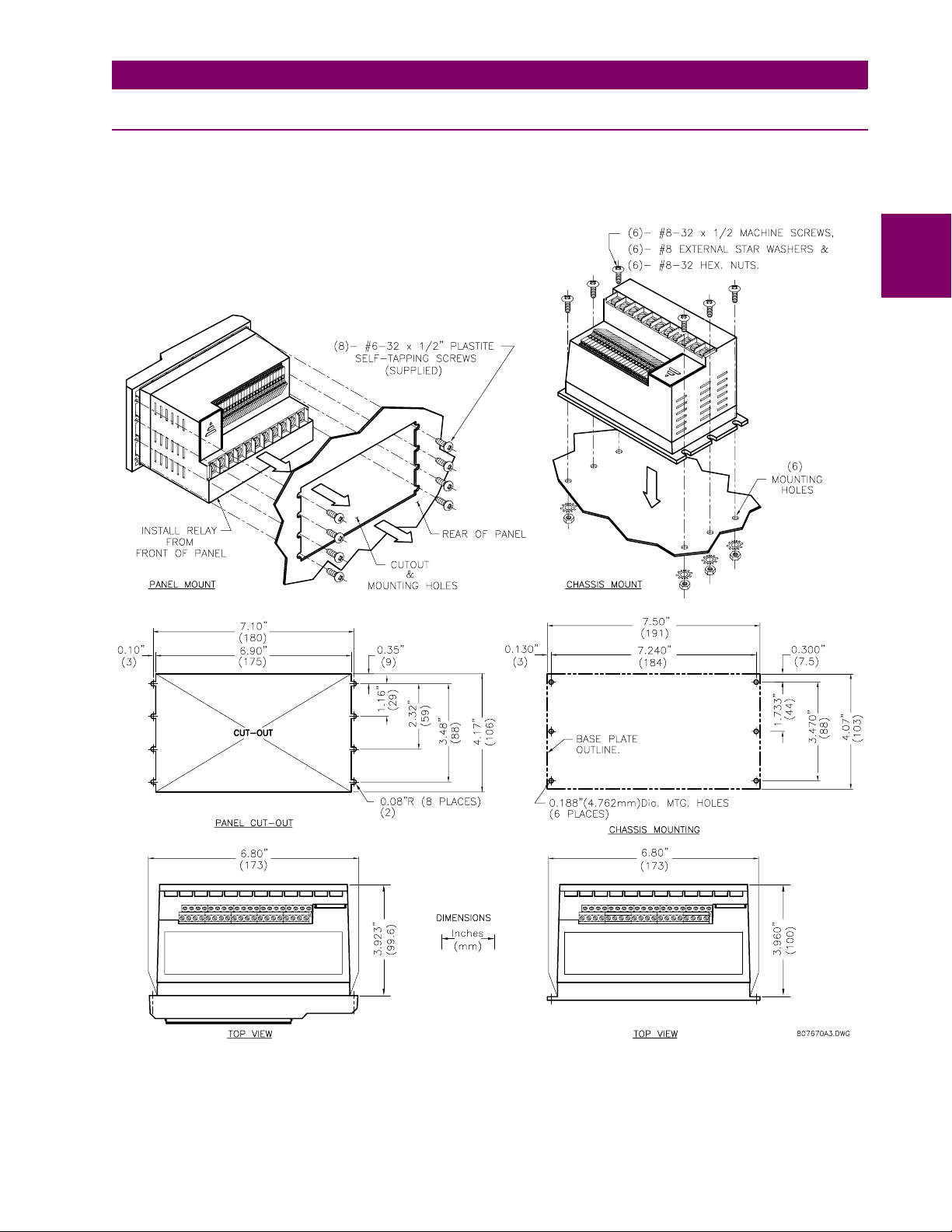
Cut the panel as shown below to mount the MM2. Use either the #8-32 or #6×½” mounting screws
provided to mount the MM2 to the panel.
2.1 MOUNTING 2.1.1 DESCRIPTION
2
GE Power Management
Figure 2–1: MM2 MOUNTING INSTRUCTIONS
MM2 Motor Manager 2 2-1
Page 20
2.1 MOUNTING 2 INSTALLATION
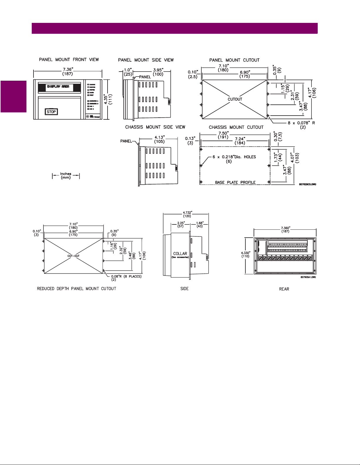
The dimensions for the standard MM2 and the MM2 with reduced mounting collar are shown below:
2
Figure 2–2: MM2 DIMENSIONS
Figure 2–3: MM2 WITH DEPTH REDUCTION COLLAR DIMENSIONS
2-2 MM2 Motor Manager 2
GE Power Management
Page 21
2 INSTALLATION 2.1 MOUNTING
2
GE Power Management
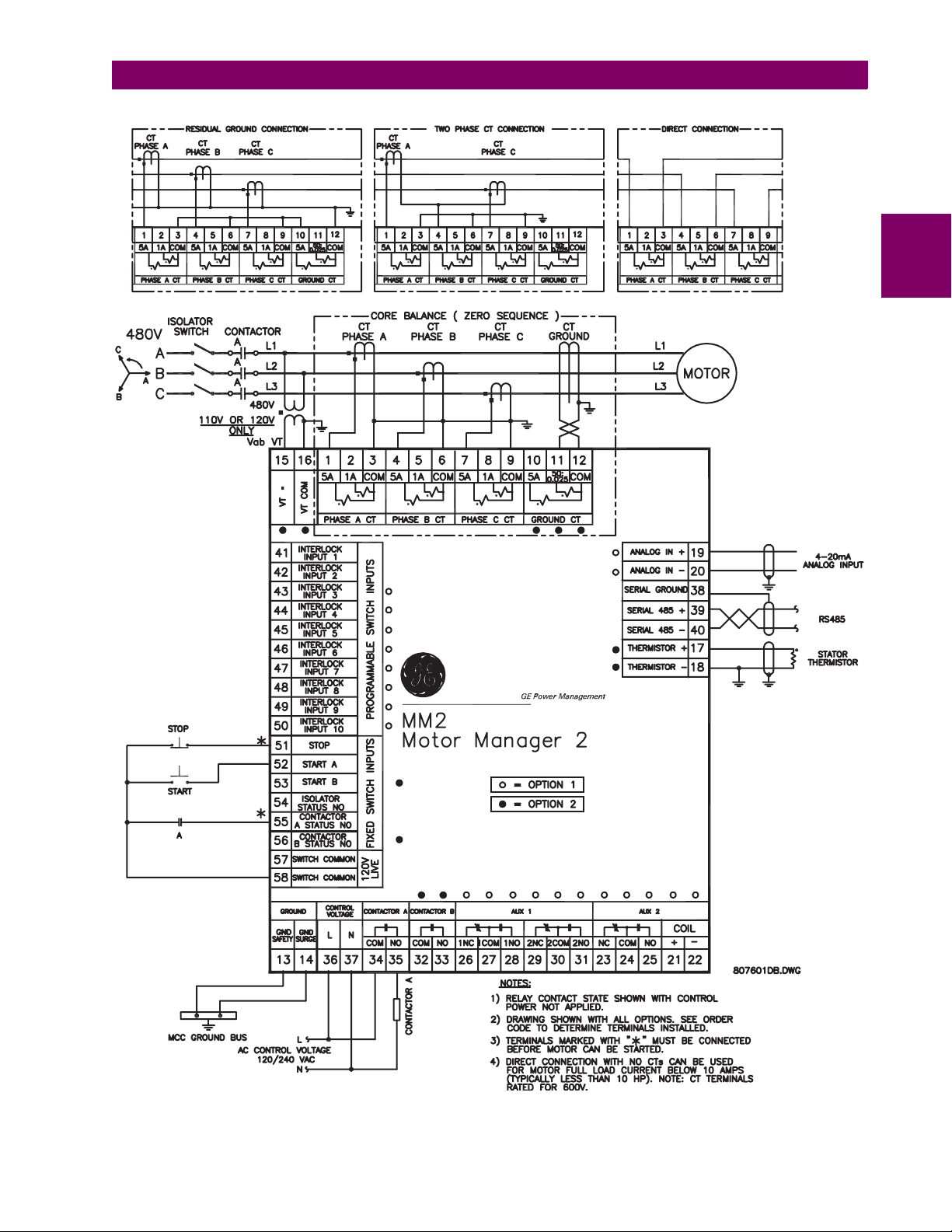
Figure 2–4: TYPICAL WIRING DIAGRAM
MM2 Motor Manager 2 2-3
Page 22

2
2.1 MOUNTING 2 INSTALLATION
52
480 VOLT BUS480 VOLT BUS
FUSEFUSE
CONTCONTACTACTOROR
PHASE PTPHASE PT
PHASE CTPHASE CT
GROUND CTGROUND CT
THERMISTOR
MOTOR
WINDINGWINDING
THERMISTTHERMISTOROR
LOAD
CONTACTOR ACONTACTOR A
(FOR(FORWARD/WYE)ARD/WYE)
CONTACTOR BCONTACTOR B
(REVERSE/DEL(REVERSE/DELTA)
51 49 37
51G
MOTOR
49
MANAGER 2MANAGER 2
46
AUXAUX
1
RELARELAY
AUXAUX
2
RELARELAY
CONTROLCONTROL
INPUTSINPUTS
4-20mA4-20mA
INPUTINPUT
RS485 REMOTERS485 REMOTE
COMMUNICACOMMUNICATIONTION
1200-19K2 BAUD1200-19K2 BAUD
PROCESSPROCESS
PLC ORPLC
OR
TRANSDUCERTRANSDUCER
Figure 2–5: MM2 FUNCTIONAL BLOCK DIAGRAM
2-4 MM2 Motor Manager 2
GE Power Management
Page 23

2 INSTALLATION 2.2 INPUTS AND OUTPUTS
2.2 INPUTS AND OUTPUTS 2.2.1 PHASE CT INPUTS
Both 5 A and 1 A current transformer secondaries are accommodated by the MM2. Each phase current input to the MM2 has 3 terminals: 5 A input, 1 A input, and the common input. For example, if th e
phase CTs are 200:5, connect phase 1, 2, and 3 CT secondaries to terminals 1/3, 4/6, and 7/9,
respectively. For motor full-load currents up to 10 A, the phase conductors can be direct connected
to the MM2 with no phase CTs required providing that the voltage at the CT terminals does not
exceed 600 V RMS.
CTs should be selected to be capable of supplying the required current to the total secondary load
which includes the MM2 relay burden of 0.1 VA at rated secondary current and the connection wiring
burden. The CT must not saturate under maximum current conditions which can be up to 8 times
motor full load during starting.
2.2.2 GROUND FAULT CT INPUT
The ground CT has a 5 A input, a 50:0.025 input, and a common input. The 5 A input on the ground
CT is used for 5 A secondary CTs or for residual connection of phase CTs. Residual ground fault protection provides a sensitivity of 5% of motor Phase CT Primary. The 50:0.025 core balance (zerosequence) CT input can be used for improved sensitivity when measuring the ground fault current.
2
Care must be taken when turning ON the Ground Fault Trip feature. If the interrupting
device (contactor or circ uit breaker ) is not ra ted to break gro und f ault c urr ent (l ow r esist ance
NOTE
Supply voltage of 120/240 V AC, 50 or 60 Hz, is required to power t he MM2. T he label on the back o f
the unit will specify the voltage which has been internally set inside the MM2. To change the voltage
setting, open the sliding door on the back of the MM2 and locate the supply voltage selector slide
switch. The selector slide switc h has a label af fixed to show t he 120/240 VAC positions. Set the slide
switch to the desired voltage.
This is an additional ground terminal provided for dissipating transient signals and surges. This must
be connected by a thick wire or braid to the system gro und for reliable operation.
Signal wiring is to box terminals that can accommodate wire as large as 12 gauge. CT connections
are made using #8 screw ring terminals that can accept wire as large as 8 gauge. Consult Figure 2–
4: TYPICAL WIRING DIAGRAM on page 2–3. Other features can be wired as required.
or solidly grounded systems), the feature should be disabled. The 50:025 input is only recommended to be used on resistance grounded systems. Where the system is solidly
grounded or high levels of current are to be detected use the 5 A ground input.
2.2.3 SUPPLY VOLTAGE
2.2.4 GROUND SURGE
2.2.5 EXTERNAL CONNECTIONS
GE Power Management
MM2 Motor Manager 2 2-5
Page 24

2.2 INPUTS AND OUTPUTS 2 INSTALLATION
2.2.6 THERMISTOR INPUT
Either a Positive Temperature Coefficient (PTC) or Negative Temperature Coefficient (NTC) thermistor may be directly connected to the MM2. By specifying the hot and cold thermistor resistance,
the MM2 automatically determines the thermistor type as NTC or PTC. Use thermistors with hot and
cold resistance values in the range 100 to 30000Ω. If no thermistor is connected, the thermistor
alarm and trip detection must be set to DISABLE in the S1: CONFIGURATION \ THERMISTOR page.
2
2.2.7 ANALOG INPUT
The analog input accepts an input from a standard 4 to 20 mA source. This input can be used for
process control monitoring to provide status and/or alarm and tripping signals related to the level of
the input signal. The analog input messages (S3: PROCESS \ ANALOG INPUT) can be programmed to
show a user defined name and units.
2.2.8 AUX 2 COIL
The AUX Relay 2 can be internally energized by the MM2 or externally energized by applying a 24
V DC signal to these terminals. Correct polarity is requir ed (Terminal 21 = +24 V DC, Terminal 22 = 0
V DC).
2.2.9 OUTPUT RELAYS
There are up to 4 output relays on t he MM2. Contact s witching ra ting fo r the output r elays as well can
be found in Section 1.3: SPECIFICATIONS on page 1–4.
• Contactor A Relay (34/35): non-reversing, forward, low speed, etc.
• Contactor B Relay (32/33): reversing, high speed, etc.
• AUX Relay 1 (26/27/28, 29/30/31): field programmable
• AUX Relay 2 (23/24/25): field programmable or hard-wired 24 V DC coil
2.2.10 SWITCH INPUTS
SWITCH INPUT COMMON TERMINALS 57 AND 58 ARE LIVE 120 VAC.
CAUTION
All switch inputs are opto-isolated and operate at a voltage of 120 V AC. The switch will read closed
when 120 VAC is applied to the switch terminal. This 120 V AC can be supplied from the switch common terminals (57, 58) or from an external source providing that the source is in phase with the supply voltage of the MM2.
2.2.11 PROGRAMMABLE SWITCH INPUTS
These 10 inputs can be programmed to one of a number of differ ent funct ions. Some of th e availabl e
functions are: Setpoint Access, Lockout Reset, Plant Interlock, Auto Start, Remote Permissive, and
Test. See the S3: PROCESS \ PROGRAMMABLE INPUTS page for complete list of available functions.
2-6 MM2 Motor Manager 2
GE Power Management
Page 25
2 INSTALLATION 2.2 INPUTS AND OUTPUTS
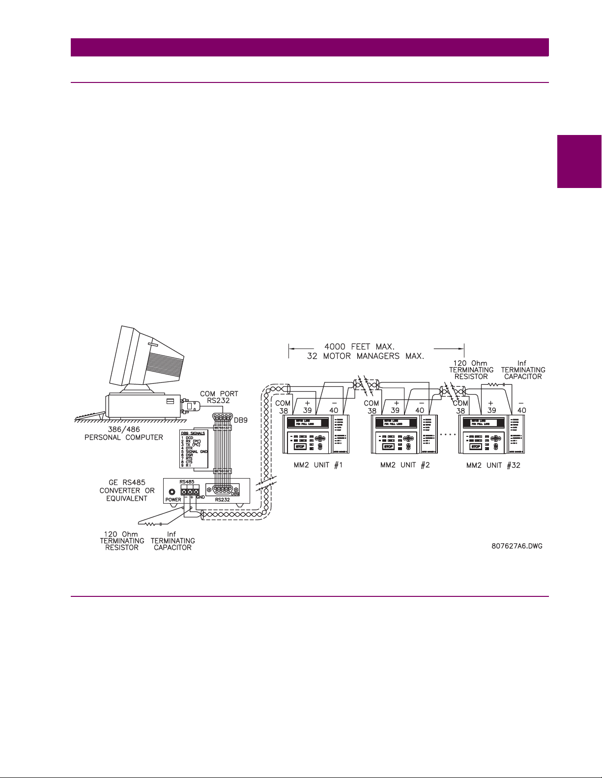
2.2.12 SERIAL COMMUNICA TION PORT
A serial port provides communication capabilities to the MM2. Multiple MM2s can be connected
together with a 24 AWG stranded, shielded twisted pair with a characteristic impedance of 120
such as Belden 9841 or equivalent. The total length of communications wiring should not exceed
4000 feet. Care should be used when routing the communications wiring to keep away from high
power AC lines and other sources of electrical noise.
Correct polarity is essential for the communications port to operate. Terminal 39 ("+") of every MM2
in a serial communication link must be connected together. Similarly, Terminal 40 ("–") of every MM2
must also be connected together. The shield wire must be connected to Terminal 38 (485 SERIAL
GROUND) on every unit in the link to provide a common ground potential for all units. Each relay
should be "daisy chained" to the next one. Avoid star or stub connected configurations if possible to
avoid potential communication problems.
A terminating resistor and capacitor network is required to prevent communication errors. Only the
last MM2 and the master computer driver should have the terminating network to ensure proper
matching. Using terminating resistors and capacitors on all the MM2s would load down the communication network while omitting them at the ends could cause reflections resulting in communication
errors.
Ω
2
Figure 2–6: RS485 TERMINATION
2.2.13 STOP
If this terminal is de-energized, both contactor A and contactor B output relays will open causing the
contactor coils to de-energize. The stop input must be energized before the MM2 will process any
start commands.
GE Power Management
MM2 Motor Manager 2 2-7
Page 26

2.2 INPUTS AND OUTPUTS 2 INSTALLATION
2.2.14 START A / START B
When the start input terminals are energized, the corresponding contactor output relay will be energized provided all other valid start conditions are met. If any trip occurs, both contactor outputs will
be de-energized. Start A input is used for all types of contactors, that is: Full Voltage Non-reversing,
Reversing, Two Speed (low speed), Wye Delta Open Trans iti on, Inver ter, Slip Ring, Autotransformer,
Part Winding or Wye Delta Closed Transition. Start B input is used for Reversing and Two Speed
2
(high speed) contactor control. Start inputs are usually momentary unless Two Wire control is
selected. Start A and B commands may also be initiated via the seri al link.
2.2.15 LOCAL ISOLATOR N/O
The local isolator NO auxi liar y c ontacts are used to pr event motor star ts i n t he event of t he Local Iso lator being in the “open” position. To prevent starts, the MM2 produces a trip when the Local Isolator
input is open. A Local Isolator Trip is automatically reset when the Local Isolator is re-closed. The
Local Isolator input can be enabled or disabled as required. The factory default is disabled.
2.2.16 CONTACTOR STATUS
The MM2 must know the state of the contactor at all times in order to detect discr epancies in contac tor close/open commands and also to display the state of the contactor. There are two contactor status inputs on the MM2, one for contactor A, the other for contactor B.
Auxiliary contacts mechanically linked to the contactor itself are used to feed back to the contactor
status inputs. No status change following a "start" command indicates an open contactor control circuit and no status change following "stop" command indicates a welded contactor. Appropriate messages and alarms are displayed for these conditions and the status can be read via the serial port.
If the motor contactor is externally energized, the MM2 will seal in the output relay and display an
“EXTERNAL START” message. If the motor contactor is externally de-energized, the MM2 will drop
out the output relay and display an “EXTERNAL STOP” message.
2.2.17 SWITCH COMMON
These two terminals serve as the common for all switches. The MM2 switch inputs operate at 120
VAC which is supplied from these terminals.
2.2.18 DIELECTRIC STRENGTH TESTING
It may be required to test a complete MCC with MM2s installed for dielectric strength. This is also
known as "flash" or "hi-pot" testing. The MM2 is rated for 1500 V AC for 1 minute or 1800 VAC for 1
second isolation between switch inputs, relay outputs, VT voltage input, supply voltage inputs and
ground terminal 13.
When performing dielectric test s, the connect ion to t he sur ge ground t erminal (14) must b e removed .
A filter network is used on the AC input to filter out RF and EMI noise. The filter capacitors and transient absorbers could be damaged by the high voltages relative to surge ground on the AC input.
Under no circumstances should any inputs other than switches, relays, supply voltage, VT input, and CT inputs be dielectric tested.
WARNING
2-8 MM2 Motor Manager 2
GE Power Management
Page 27
3 HARDWARE 3.1 FACEPLATE FUNCTIONS
3 HARDWARE
3.1 FACEPLATE FUNCTIONS 3.1.1 DESCRIPTION
Once the MM2 has been wired and powered on, it is ready to be programmed for a specific application. Local programming is done using the front panel keypad and the 40 character alphanumeric
display. Remote programming via the serial port is also possible using the MM2PC
®
software.
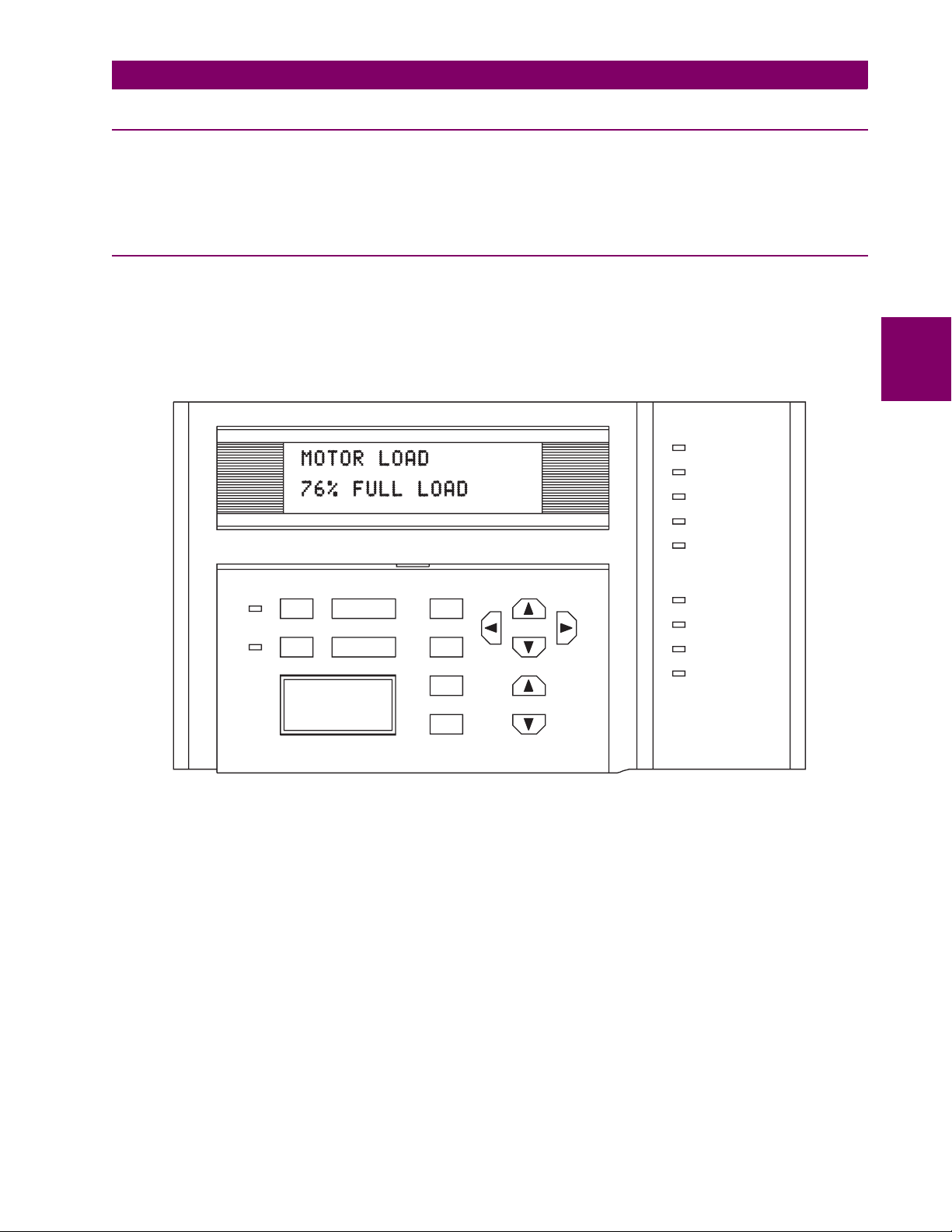
3.1.2 MESSAGE DISPLAY
A 40 character display is used to communicate all information about the syste m to the user. Trip and
alarm messages will automatically override the currently-displayed message. If no key is pressed for
2 minutes, a user-selected default messaging sequence will be displayed. If the motor is currently
stopped, the Motor Status message will be the default message. Once the motor is started, the first
user-selected message will appear.
RUNNING
STOPPED
TRIPPED
ALARM
FAULT
3
START AAUTO
MANUAL START B
STOP
SETPOINT
MESSAGE
ACTUAL
RESET
VALUE
STORE
Figure 3–1: FRONT PANEL
CONTACTOR A
CONTACTOR B
AUX 1
AUX 2
807230A1.CDR
GE Power Management
MM2 Motor Manager 2 3-1
Page 28

3.1 FACEPLATE FUNCTIONS 3 HARDWARE
3.1.3 INDICATOR LEDs
• RUNNING: Whenever contactor A and/or B relays are closed and the contactor status inputs
acknowledge the correct state, the RUNNING indicator will be on. Current flow does not affect
the indicator, only contactor status.
• STOPPED: If both contactors A and B are in the OFF state, the STOPPED indicator will be on.
• TRIPPED: If a trip condition causes the A or B contactor relays to de-energize, this indicator will
be on. As long as this indicator is on, the motor cannot be started. It is cleared using the reset
key, lockout reset facility or serial port reset, dependent on the type of trip.
• ALARM: If an alarm condition is present this indicator will be on. Use the A2: ALARM DATA actual
3
values to view current alarm status.
• FAULT: If an internal fault within the MM2 is detected by self-checking, this indicator will be on.
The MM2 must be replaced or repaired.
• CONTACTOR A: If the Contactor A Relay is energized, this indicator will be on.
• CONTACTOR B: If the Contactor B Relay is energized, this indicator will be on.
• AUX 1: If Auxiliary Relay # 1 is on, this indicator will be on.
• AUX 2: If Auxiliary Relay # 2 is on, this indicator will be on.
• AUTO: If the MM2 is in Auto control mode or the Hard-Wired Auto mode, this indicator will be on.
In Auto mode the Start A / Start B switch inputs and START A / START B keypad keys are nonoperational but serial port st art commands are operati onal. In the Hardwir ed Auto Mode, the Auto
Start A and Auto Start B switch inputs are functional in conjunction with the Auto Permissive
switch input. Serial, faceplate and remote starts are disabled. STOP commands from any location are always operational.
• MANUAL: If the MM2 is in Manual control mode, this indicator will be on. In Manual mode the
Start A / Start B switch inputs, AUTO START A / AUTO START B switch inputs and START A /
START B keypad keys are operational but serial port start commands are ignored. All stop commands are operational.
3-2 MM2 Motor Manager 2
GE Power Management
Page 29

3 HARDWARE 3.2 KEYPAD
3.2 KEYPAD 3.2.1 SETPOINTS KEY
FUNCTION: The SETPOINT key allows the user to examine and alter all trip, alarm, and other MM2
setpoints. There are 6 pages of Setpoints:
• Page 1: Configuration
• Page 2: Protection
• Page 3: Process
• Page 4: Control
• Page 5: Monitoring
• Page 6: Factory Data
EFFECT: Pressing this key will cause the display to show the beginni ng of the next page of setpoints
data. If Actual Values data was on the disp lay bef ore pressing th e SETPOINT k ey, setpoints page S1
will be shown:
]] SETPOINTS
]] S1: CONFIGURATION
USE: This key can be pressed at any time to view MM2 setpoints. To scroll through the setpoint
pages, press the SETPOINT key. To go from section to section within a page, press the MESSAGE
UP and MESSAGE DOWN keys. To go from line to line within a section, press the MESSAGE LEFT
and MESSAGE RIGHT keys.
To alter a setpoint, the VALUE UP and VALUE DOWN keys can be used. All setpoints can be incremented or decremented to pre-determined limits. When the desired value is reached, the STORE
key must be used to save the n ew set point. If an a lt ered set poin t is n ot s tored, the previous val ue will
still be in effect. All control and protection features continue to operate while setpoints data is displayed.
3.2.2 ACTUAL VALUES KEY
FUNCTION: The ACTUAL key allows the user to examine all of the actual motor operating parame-
ters. There are 4 pages of ACTUAL VALUES data:
3
• Page 1: Data
• Page 2: Status
• Page 3: Inputs
• Page 4: Statistics
EFFECT: Pressing this key will cause the display to show the beginning of the next page of Actual
Values data. If setpoints data was on th e displ ay befor e pressin g t he ACTUAL key, page A1 of Actual
Values will be shown:
]] ACTUAL VALUES
]] A1: DATA
GE Power Management
MM2 Motor Manager 2 3-3
Page 30

3.2 KEYPAD 3 HARDWARE
USE: This key can be pressed at any time to view MM2 actual values. To scroll through the actual
values pages, press the ACTUAL key. To go from section to section within a page, press the MESSAGE UP and MESSAGE DOWN keys. To go from line to line within a section, press the MESSAGE
LEFT and MESSAGE RIGHT keys.
The VALUE UP and VALUE DOWN keys have no effect when actual values data is displayed.
3.2.3 STORE KEY
FUNCTION: The STORE key allows the user to store new setpoints into th e MM2 internal memory.
EFFECT: When this key is pressed the currently displayed Setpoint will be stored in non-volatile
memory and will immediately come into effect. When a Setpoint is stored, the following flash mes-
3
sage will appear on the display:
NEW SETPOINT
STORED
USE: The STORE key can be used only in SETPOINTS mode to store new setpoints, or in ACTUAL
VALUES mode to select a new default message.
3.2.4 STOP KEY
FUNCTION: The STOP key will allow the user to stop the motor from the face plate of the MM2.
EFFECT: Pressing this key will cause the Contactor A and Contactor B output relays to de-energize
therefore dropping out the motor contactor.
USE: The STOP key is used to stop the motor.
3.2.5 RESET KEY
FUNCTION: The RESET key allows the user to reset MM2 trips.
EFFECT: Pressing this key will reset a tri pped stat e on the MM2. A message i ndicati ng that a r eset i s
not possible will be displayed if the condition causing the trip is still present.
USE: The RESET key can be used to reset all trip conditions from the faceplate of the MM2. A
Ground Fault, Stalled Rotor and Overload Trip can be assigned to the LOCKOUT RESET feature on
one of the programmable switch inputs for adde d safety. The factory default allows the resetting of all
trips using the front panel reset key.
3.2.6 START A KEY
FUNCTION: The START A key can be used to start the motor.
EFFECT: Pressing this key will cause the programmed start sequence to begi n.
USE: The START A key is used to sta rt the motor from the faceplate of the MM2. Start A can also be
initiated from the start switch inputs at the back of the MM2 or from the serial port.
3-4 MM2 Motor Manager 2
GE Power Management
Page 31

3 HARDWARE 3.2 KEYPAD
3.2.7 START B KEY
FUNCTION: The START B key can be used to start the motor.
EFFECT: Pressing this key will cause the programmed start sequence to begi n.
USE: This START B key is used to start a reversing or two speed motor from the faceplate of the
MM2. Start B can also be initiated from the start switch input at the back of the MM2 or from the
serial port.
3.2.8 MESSAGE UP/DOWN KEYS
FUNCTION: The MESSAGE UP and MESSAGE DOWN keys allow the user to move to the next or
previous section of the currently selected page.
EFFECT: Pressing the MESSAGE DOWN key will cause the display to move to the next section of
the current page. Pressing the MESSAGE UP key will cause the display to move to th e previous section of the current page. Note: If either key is held for more than 1 second, the next or previous sections will be selected at a fas t rate. When the c urrent display is a t a page heading, t he MESSAGE UP
key has no effect. When the curr ent displ ay is at t he end of the page, the MESSAGE DOWN key has
no effect.
USE: These keys are used to move through the sections of the currently selected page.
3.2.9 MESSAGE LEFT/RIGHT KEYS
FUNCTION: The MESSAGE LEFT and MESSAGE RIGHT keys allow the user to scan the next or
previous line of the currently selected section.
EFFECT: Pressing the MESSAGE RIGHT key displays the next line of the current section. Pressing
the MESSAGE LEFT key displays the previous line of the current section. If either key is held for
more than 1 second, the next or previous line will be selected at a faster rate. If the display shows a
section heading, the MESSAGE LEFT key has no effect. If the MESSAGE RIGHT key has no effect,
the display is showing the last line of a section.
USE: These keys are used to move through the lines of the currently selected sect ion.
3
3.2.10 VALUE UP/DOWN KEYS
FUNCTION: The VALUE UP and VALUE DOWN keys allow the user to change setpoint values prior
to pressing the STORE key.
EFFECT: Pressing the VALUE UP key will increment the currently displayed setpoint value. Pressing
the VALUE DOWN key will decrement the currently displayed setpoint value. If the display shows an
Actual Value these keys will have no effect
USE: These keys can be used any time to change the value displayed in the setpoint messages.
GE Power Management
MM2 Motor Manager 2 3-5
Page 32

3.3 THEORY OF OPERATION 3 HARDWARE
3.3 THEORY OF OPERATION 3.3.1 HARDWARE DESCRIPTION
A 16 bit 68HC16 microc ontroller IC performs program execution and control logic for the MM2. Refer
to the block diagram for a complete overview of the MM2 circuitry. It has an 8 or 16 bit bus width
which can be selected dynamically with each external memory fetch allowing a mix of 8 and 16 bit
devices. Internal clock rate is 16 Mhz. Instructions are stored in two 128K×8 bit flash memory, data
is stored in an 32K×8 RAM while Setpoints and accumulated data are stored in a 8K×8 EEPROM.
An intelligent display module with its own microprocessor, memory and command set is accessed
through a buffer on the data bus. The display, a 4×4 keypad and the front panel LEDs are multiplexed through the same buffer.
External switch inputs ar e driven with 120 VAC whi ch triggers an optocoupler for isolation. All control
3
logic based on the state of these inputs determines operation of up to 4 output relays which are also
driven from a latch under program control. Like the inputs, the relay outputs are driven from an isolated power supply and optocoupler to prevent switch ing transient energy from affecting the CPU.
A 10 bit successive approximation A/D on the 68HC16 CPU with 8 channels is used to measure all
analog signals. Separate AC inp uts for phase 1 , phase 2, phase 3, and g round f ault sig nals are sampled at a 1.67 ms rate, squared and summed. RMS current is then determined by deriving the
square root of the sampled waveform over several cycles. The sampling time is set to measure an
integral number of cycles to reduce the affects of noise and harmonics. Thermistor, analog input, VT
voltage, control supply voltage and internal reference voltage are also monitored. An external precision 5V DC reference is used as the input reference for the A/D converter.
When power to the unit is removed, a small 8-bit processor (68HC705) will continue to operate for a
period of at least 1 hour. This processor is powered from a large backup capacitor. The 68HC705
accurately measures the time that the MM2 has been without control power. When power is reapplied the main processor will read the time off from the small processor and then very accurately
calculate the thermal capaci ty value. This time off value is also used for the undervoltage restart feature.
Serial communications at up to 19200 baud is implemented with UART circuitry internal to the
68HC16 microcomputer. All necessary timing and control is performed inside the chip. An external
transceiver chip converts the digital data to an RS485 interface. Direction, receive data and transmit
data are on the input side with a two wire twisted pair driver on the output.
AC control voltage to power the MM2 can be selected as 120 or 240 V AC using a switch and dual
wound primary transformer. A filter is incorporated between the incoming supply and transformer primary to prevent transients from affecting the circuitry.
Separate, isolated secondary supplies are used for CPU power, I/O and communication drivers.
Optocoupling and transformer coupling are used between isolated circuits to prevent transients from
upsetting program execution. The 68HC705 is used to provide separate watchdog timer and power
fail monitoring control to ensure that the main CPU starts and operates under any input voltage conditions. Should normal program execution fail, the 68HC705 reset s the main CPU.
3-6 MM2 Motor Manager 2
GE Power Management
Page 33

3 HARDWARE 3.3 THEORY OF OPERATION
3
GE Power Management
Figure 3–2: BLOCK DIAGRAM
MM2 Motor Manager 2 3-7
Page 34

3
3.3 THEORY OF OPERATION 3 HARDWARE
3-8 MM2 Motor Manager 2
GE Power Management
Page 35

4 SETPOINTS 4.1 OVERVIEW
4 SETPOINTS
4.1 OVERVIEW 4.1.1 DESCRIPTION
By pressing the SETPOINT key, any of the motor trip/alarm Setpoints may be viewed or altered. Setpoints data is divi ded into si x pages. I nformati on a bout the conf ig urati on of t he mot or as wel l as othe r
connected devices is entered in page one, S1: CONFIGURATION. Information for programming the
protection features is located in page two, S2: PROTECTION. Information describing the process
control functions is described in page three, S3: PROCESS. Information for programming the cont rol
functions in the MM2 is contained in page four, S4: CONTROL. Information to aid with plant maintenance is contained in page five, S5: MONITORING. Information about the internal configuration of
the MM2 as well as the software version is contained in page, S6: FACTORY DATA.
To scroll through the Setpoint pages, press the SETPOINT key. When this key is pressed for the first
time the following message will appear on the display:
]] SETPOINTS
]] S1: CONFIGURATION
This is the first page of Setpoints. The MESSAGE RIGHT, MESSAGE LEFT, MESSAGE UP and
MESSAGE DOWN keys may be used to view all of the setpoints data.
The Setpoint values themselves are changed by pressing the VALUE UP or VALUE DOWN keys
until the desired value is reached. When a Setpoint is adjusted to its proper value the STORE key
must be pressed in order to store the Setpoint into the MM2 non-volatile memory. Once the STORE
key is pressed the flash mess age shown below will appear on the displa y and the new Setpo int value
will be permanently saved.
4
NEW SETPOINT
STORED
Setpoints may be changed while the motor is running; however it is not recommended to change important protection parameters without first stopping the motor.
WARNING
Setpoints will remain stored indefinitely in the MM2 internal non-volatile memory even when control
power to the unit is removed. Protection parameters are based on the entered data. This data must
be complete and accurate for the given system for reliable protection and operation of the motor.
All Setpoint messages shown contain the factory defaul t settings.
NOTE
4.1.2 ABBREVIATIONS
The following abbreviations are used in the messages in the setpoints pages.
• A, AMPS: Amperes
• AUX: Auxilia ry
• CBCT: Core Balance Current Transformer
• COM, COMMS: Communication
• CT: Current Transformer
• FLC: Full Load Current
• FV: Full Voltage
• G/F: Ground Fault
GE Power Management
MM2 Motor Manager 2 4-1
Page 36

4.1 OVERVIEW 4 SETPOINTS
• GND: Ground
•Hz: Hertz
• KOHMS: kiloOhms
• MAX: Maximum
• MIN: Minim um
• SEC, s: Seconds
• UV: Undervoltage
• VT: Voltage Transformer
4
]] SETPOINTS
]] S1: CONFIGURATION
] COMMUNICATION
]
] MOTOR
] IDENTIFICATION
] STARTER
]
] CT/VT INPUTS
]
] THERMISTOR
]
] FAULT MODE
]
] STATISTICS
]
] PROGRAMMABLE
] MESSAGES
]] SETPOINTS
]] S2: PROTECTION
] MOTOR PROTECTION
] THERMAL
] MOTOR PROTECTION
] GROUND FAULT
] MOTOR PROTECTION
] OPTIONS
] LOAD PROTECTION
]
] UNDER/OVERVOLTAGE
] PROTECTION
]] SETPOINTS
]] S3: PROCESS
] PROGRAMMABLE
] INPUTS
] PROCESS INTERLOCK
] NAMES
] STOP CONFIGURATION
]
] ANALOG INPUT
]
]] SETPOINTS
]] S4: CONTROL
] UNDERVOLTAGE
] AUTO RESTART
] AUX RELAY 1 CONFIG
]
] AUX RELAY 2 CONFIG
]
] PREFERENCES
]
]] SETPOINTS
]] S5: MONITORING
] PLANT CONDITION
]
] PRESET COUNTERS
] AND TIMERS
Figure 4–1: SETPOINTS MESSAGES
4-2 MM2 Motor Manager 2
]] SETPOINTS
]] S6: FACTORY DATA
] PRODUCT FIRMWARE
] IDENTIFICATION
] PRODUCT MODEL
] IDENTIFICATION
] FACTORY SEVICE
] DATA
GE Power Management
Page 37

4 SETPOINTS 4.2 S1 CONFIGURATION
4.2 S1 CONFIGURATION 4.2.1 DESCRIPTION
This page is used to enter all information about the configuration of the MM2 and the motor being
protected by the MM2. Setpoints Page 1 is divided into eight sections, COMMUNICATIONS,
MOTOR IDENTIFICATION, STARTER, CT / VT INPUTS, THERMISTOR, FAULT MODE, STATISTICS, PROGRAMMABLE MESSAGE and PREFERENCES.
4.2.2 COMMUNICATIONS
P ATH: SETPOINTS t S1: CONFIGURATION t COMMUNICATIONS
COMMUNICATIONS
ADDRESS: OFF
BAUD RATE: 9600
PARITY: NONE
P ATH: SETPOINTS t S1 CONFIGURATION tt MOTOR IDENTIFICATION
MOTOR NAME:
MOTOR
MOTOR RATING
OFF kW
HIGH SPEED MOTOR
RATING: OFF kW
SYSTEM SUPPLY:
480 V
Range: 1 to 255 or OFF, Step: 1
Each MM2 on the same serial communication network must have a
unique address in the range of 1 to 255. Computer software driving the
serial network must be configured to recognize each separate address.
Range: 1200, 2400, 4800, 9600, 19200
Selects the data transfer rate for Modbus serial communications.
Range: NONE, ODD, EVEN
This setpoint determines what type of parity checking is used when communicating to the MM2.
Range: 20 ASCII characters
Enter a motor name that will appear in the actual values message
A1: DATA \ MOTOR DATA \ MOTOR STATUS.
Range: 0.3 kW to 1100 kW or OFF; Step: 0.1 kW
Enter the motor rating (or low speed motor rating for two speed starters)
in kWs on this line. This message is for reference only and does not
affect operation of the MM2.
Range: 0.3 kW to1100 kW or OFF, Step: 0.1 kW
Enter the high speed motor rating (applicable for Two Speed starters
only) in kWs on this line. This message is for reference only and does
not affect operation of the MM2.
Range: 110 V to 600 V; Step: 1 V
Enter system supply voltage on this line. This message is for reference
only and does not affect operation of the MM2.
4
4.2.3 MOTOR IDENTIFICATION
GE Power Management
MM2 Motor Manager 2 4-3
Page 38

4.2 S1 CONFIGURATION 4 SETPOINTS
4.2.4 STARTER
PATH: SETPOINTS t S1: CONFIGURATION
STARTER TYPE:
OFF
CHANGE OVER CURRENT
1.5 xFLC
4
CHANGE OVER TIME:
30 s
TRANSFER TIME:
10 s
HIGH SPEED START
BLOCK: DISABLE
RAMP UP TIME:
5 s
RAMP DOWN TIME:
5 s
STAGE ONE SHORTING
TIME: 5 s
STARTER
ttt
Range: OFF, FV NON-REVERSING, FV REVERSING, WYE DELTA
OPN TRANS, TWO SPEED, INVERTER, SLIP RING,
AUTOTRANS OPN TRANS, PART WINDING, WYE DELTA
CLS TRANS, AUTOTRANS CLS TRANS, DUTY/STANDBY,
SOFT STARTER, WYE DELTA OPN TRANS
Select a type according to the configuration that the MM2 is controlling.
This will determine the control logic used for Contactor A and Contactor
B start and stop sequences. See Chapter 9: STARTER TYPES for a
detailed description of each starter type.
Range: 1.0 to 5.0 x FLC or OFF; Step: 0.1 x FLC
Appears only when STARTER TYPE is WYE DELTA OPN TRNS or WYE DELTA
CLS TRANS. Before CHANGE OVER CURRENT comes into effect on a wye
delta start, a minimum of 25% of the CHANGE OVER TIME must have
expired. After 25% of the time has expired and the average of the three
phase currents has dropped below the CHANGE OVER CURRENT value, the
transition from wye (Contactor A) to delta (Contactor B) will occur. If this
setpoint is OFF, 100% of the CHANGE OVER TIME must expire for the wye to
delta transition to occur.
RANGE: 1 to 100 seconds; Step: 1 second
Appears only if STARTER TYPE is set a s WYE DELTA OPN TRNS or WYE DELTA
CLS TRANS. See CHANGE OVER CURRENT setpoint above for operation.
Range: 1 to 125 seconds; Step: 1 second
Appears only if STARTER TYPE is set as FV REVERSING or TWO SPEED. With
two-speed starters, this delay is required when the motor is switched
from high speed (Contactor B) to low speed (Contactor A). The delay
starts when Contactor B drops out. With a reversing starter, this delay
occurs when switching from forward (Contactor A) to reverse (Contactor
B) and from reverse to forward.
Range: ENABLE, DISABLE
Appears only if STARTER TYPE is TWO SPEED. When disabled, the MM2
allows the motor to be started directly to high speed. When enabled, the
motor must be started in low speed before switching to high speed.
Range: 1 to 125 seconds; Step: 1 second
Appears only if STARTER TYPE is selected as INVERTER. See the descrip-
tion of the Inverter starter type for details on functionality.
Range: 1 to 125 seconds; Step: 1 second
Appears only if STARTER TYPE is selected as INVERTER. See the descrip-
tion of the Inverter starter type for details on functionality.
Range: 1 to 125 seconds; Step: 1 second
Appears only if STARTER TYPE is SLIP RING or PART WINDING. This is the
time delay from the closure of Contac tor A to the closure of Contactor B.
4-4 MM2 Motor Manager 2
GE Power Management
Page 39

4 SETPOINTS 4.2 S1 CONFIGURATION
CONTACTOR SEQUENCE:
1S-2S
CHANGE OVER TIME:
5 s
STARTS PER HOUR:
5
P ATH: SETPOINTS t S1: CONFIGURATION
PHASE CT PRIMARY
AMPS: 100
HIGH SPEED PHASE CT
PRIMARY AMPS: 100
GROUND FAULT CT
INPUT:50:0.025 CBCT
GROUND CT PRIMARY
AMPS: 100
50:0.025 HI-RES
DISPLAY: DISABLE
VT PRIMARY VOLTAGE:
OFF V
Range: 1S-2S, 2S-1S
Appears only if STARTER TYPE is AUTOTRANS OPN TRANS. The 1S-2S value
closes the 1S contactor ahead of the 2S contactor as per some manufacturer wiring practices. The 2S-1S value means that the 2S contactor
will close ahead of the 1S contactor, another common wiring practice.
Range: 1 to 125 seconds; Step: 1 second
Appears only if STARTER TYPE is AUTOTRANS OPN TRANS or AUTOTRANS CLS
TRANS. This is the time delay from the closure of Contactor A until the
opening of Contactor A.
Range: 1 to 40 starts/hour or OFF; Step: 1
Limits the number of starts per hour to prevent over heating of windings.
Range: 5 to 1000 A; Step: 5 A
Enter the phase CT rated primary amps; e.g. if the phase CTs are rated
500:5, enter 500. The CT secondary must be connected to the correct
input, i.e. 1 A or 5 A.
Range: 5 to 1000 A; Step: 5 A
Appears only if STARTER TYPE is TWO SPEED. Enter the high speed CT
rated primary amps. In effect only when Contactor B is energized.
Range: 50:0.025 CBCT, 5 A SEC CBCT, 5 A RESIDUAL
Enter the ground sensing used, either sensitive 50:0.025 core balanced
ground fault CT, 5 A sec. core balanced CT, or 5 A Residual for residual
ground fault current sensing from the 5 A phase CT secondaries.
Range: 5 to 1000 A; Step: 5 A
Appears only if 5A SEC CBCT is selected for the GROUND FAULT CT INPUT.
Enter the GFCT rated primary amps.
Range: Enable, Disable
Increases the displayed resolution to 2 decimal points for the 50:0.025
ground input.
Range: 110 to 600 V or OFF; Step: 1 V
Enables/disables the voltage/power feat ures and sets VT primary volts.
tttt
4.2.5 CT / VT INPUTS
CT/VT INPUTS
4
VT CONNECTION TYPE:
PHASE (A-N)
VT SECONDARY
VOLTAGE: 120V
NOMINAL FREQUENCY:
60 Hz
GE Power Management
Range: PHASE (A-N), LINE (A-B)
Appears only if the VT PRIMARY VOLTAGE setpoint is not set to OFF. Enter
the type of VT connection: PHASE A-N (V
) or LINE A-B (Vab).
an
Range: 110 V, 120 V
Appears only if the VT PRIMARY VOLTAGE setpoint is not set to OFF.
Range: 50 Hz, 60 Hz
MM2 Motor Manager 2 4-5
Page 40

4.2 S1 CONFIGURATION 4 SETPOINTS
4.2.6 THERMISTOR
PATH: SETPOINTS t S1: CONFIGURATION
COLD RESISTANCE:
0.1 kOHMS
HOT RESISTANCE
5.0 kOHMS
THERMISTOR TRIP:
DISABLE
4
THERMISTOR ALARM:
DISABLE
ttttt
THERMISTOR
Range: 0.1 to 30.0 kOHMS; Step: 0.1
For a PTC thermistor, enter the resistance that the thermistor must drop
below before a Thermistor T r ip or Alar m can be cl eared. For a NTC ther mistor, enter the resistance that the thermistor must rise above before a
Thermistor Tri p or Alarm can be cleared.
Range: 0.1 to 30.0 kOhms, STEP: 0.1
For a PTC thermistor, enter the resistance that the thermistor must rise
above before a Thermistor Trip or Alarm will occur. For a NTC thermistor, enter the resistance that the thermistor must drop below before a
Thermistor Tri p or Alarm will occur.
Range: ENABLE, DISABLE
When a thermistor is used, it can be selected for an Alarm or Trip or
both. Choose ENABLE to allow Thermistor Trips to occur .
Range: ENABLE, DISABLE
When a thermistor is used, it can be selected for an Alarm or Trip or
both. Choose ENABLE to allow Thermistor Alarms to occur.
4.2.7 FAULT MODE
PATH: SETPOINTS t S1: CONFIGURATION
INTERNAL FAULT TRIP
ENABLE
Range: ENABLE, DISABLE
An internal fault during self-checking will cause an alarm. Since operation may be erratic depending on the fault condition, it may be desirable
to trip the motor by set ting t his setpoi nt t o ENABLE. The MM2 continues to
run the motor with an internal fault present if set to DISABLE.
SERIAL COMM FAILURE
TRIP: OFF s
Range: 5 to 25 seconds or OFF; Step: 5 seconds
If using serial communications to control a process with several motors
working together, it may be desirable to shut down the motor if communication control is lost. When no activity occurs on the communications
port for 5 to 25 seconds, it will trip if this feature is enabled.
SERIAL COMM FAILURE
ALARM: OFF
CHANGE COMMAND MODE
ON ALARM: DISABLE
Range: 5 to 25 seconds or OFF; Step: 5 seconds
Sets an alarm when the serial communication link is interrupted.
Range: ENABLE, DISABLE
Allows the command mode to automatically switch from AUTO to MANUAL when the SERIAL COMMS FAILURE ALARM is active. If th e motor was
running when the alarm occurred it will be st opped and wil l resta rt b ased
on manual start inputs only. When serial communication is restored the
MM2 will remain in MANUAL command mode.
tttttt
FAULT MODE
4-6 MM2 Motor Manager 2
GE Power Management
Page 41

4 SETPOINTS 4.2 S1 CONFIGURATION
4.2.8 STATISTICS
P ATH: SETPOINTS t S1: CONFIGURATION
CLEAR TIMERS:
DISABLE
Range: ENABLE, DISABLE
Select ENABLE and press STORE to clear the timers on page
A4: STATISTICS \ TIMERS.
CLEAR START/TRIP
COUNTERS: DISABLE
Range: ENABLE, DISABLE
Select ENABLE and press STORE to clear the start and trip counters on
page A4: STATISTICS \ COUNTERS.
CLEAR INTERLOCK
COUNTER: DISABLE
Range: ENABLE, DISABLE
Select ENABLE and press STORE to clear the interlock counter on page
A4: STATISTICS \ COUNTERS.
CLEAR ENERGY USED:
DISABLE
Range: ENABLE, DISABLE
Select ENABLE and press STORE to clear the energy used (kWhrs) on
page A1: DATA \ MOTOR DATA.
P ATH: SETPOINTS t S1: CONFIGURATION
PROGRAMMABLE MESSAGE
SAMPLE TEXT
Range: 40 ASCII characters
Enter a 40 character message using the VALUE UP/DOWN and
STORE keys. Message is displayed in A1: PROGRAMMABLE MESSAGE.
ttttttt
tttttttt
STATISTICS
4
4.2.9 PROGRAMMABLE MESSAGE
PROGRAMMABLE MESSAGE
P ATH: SETPOINTS t S1: CONFIGURATION
DEFAULT MESSAGE
DELAY: 10 s
DEFAULT MESSAGE
BRIGHTNESS: 60%
Range: 3 to 120 seconds in steps of 1
The default message delay can now be adjusted with this setpoint.
Range: 0 to 100% in steps of 20
The display brightness can now be adjusted when it is not in use.
ttttttttt
4.2.10 PREFERENCES
PREFERENCES
GE Power Management
MM2 Motor Manager 2 4-7
Page 42

4.3 S2 PROTECTION 4 SETPOINTS
4.3 S2 PROTECTION 4.3.1 DESCRIPTION
This page is used to enter all information about the protection of the motor and the load. Setpoints
Page 2 is divided into four sections, MOTOR PROTECTION THERMAL, MOTOR PROTECTION
GROUND FAULT, MOTOR PROTECTION OPTIONS, LOAD PROTECTION and UNDER/OVERVOLTAGE PROTECTION.
4.3.2 STANDARD OVERLOAD CURVES
Table 4–1: STANDARD OVERLOAD CURVE TRIP TIMES (IN SECONDS)
4
OVERLOAD
LEVEL
1.05 7200 7200 7200 7200 7200 7682 10243 12804
1.10 416 833 1250 1666 2916 3750 5000 6250
1.20 198 397 596 795 1392 1789 2386 2982
1.30 126 253 380 507 887 1141 1521 1902
1.40 91 182 273 364 638 820 1093 1367
1.50 70 140 210 280 490 630 840 1050
1.75 42 84 127 169 297 381 509 636
2.00 29 58 87 116 204 262 350 437
2.25 21 43 64 86 150 193 258 323
2.50 16 33 50 66 116 150 200 250
2.75 13 26 39 53 93 119 159 199
3.00 10 21 32 43 76 98 131 164
3.50 7.8152331546993116
4.00 5.811172340526987
1 2 3 4 5 6 7 8
CURVE NUMBER
4.50 4.5 9 13 18 31 40 54 68
5.00 3.6 7.2 10 14 25 32 43 54
5.50 3 6 9 12 20 26 35 44
6.00 2.557.51017223037
6.50 2.1 4.2 6.3 8.4 14 19 25 31
7.00 1.8 3.6 5.4 7.2 12 16 21 27
7.50 1.6 3.2 4.8 6.4 11 14 19 23
8.00 1.4 2.8 4.2 5.6 9.8 12 16 20
The standard overload curves are shown in the following chart. Note that K+E 11” x 17” format of
time/overcurrent curves are available from factory upon request.
4-8 MM2 Motor Manager 2
GE Power Management
Page 43

4 SETPOINTS 4.3 S2 PROTECTION
MM2/MM3 STANDARD TIME/CURRENT
OVERLOAD CURVES
GE POWER MANAGEMENT
100000
10000
4
1000
TIME (SECONDS)
100
10
CURVE #CURVE #
8
7
6
5
4
3
2
1
.05
Figure 4–2: GE POWER MANAGEMENT TIME/OVERCURRENT CURVES
GE Power Management
1
0.1
0.5
1
2
3
456
789
10
20
MULTIPLE OF PICKUP CURRENT (PER UNIT)
MM2 Motor Manager 2 4-9
50
807638D4.CDR
100
Page 44

4.3 S2 PROTECTION 4 SETPOINTS
4.3.3 NEMA COMPATIBLE OVERLOAD CURVES
Table 4–2: NEMA COMPATIBLE OVERLOAD CURVE TRIP TIMES (IN SECONDS)
4
OVERLOAD
LEVEL
1.05 3349 5024 6698 10047
1.10 1635 2452 3269 4904
1.20 780 1170 1560 2340
1.30 497 746 995 1492
1.40 358 536 715 1073
1.50 275 412 549 824
1.75 166 250 333 499
2.00 114 172 229 343
2.25 84 127 169 253
2.50 65 98 131 196
2.75 52 78 105 157
3.00 43 64 86 129
3.50 30 46 61 91
4.00 23 34 46 67
CLASS 10 CLASS 15 CLASS 20 CLASS 30
CURVE
4.50 17.8 27 36 53
5.00 14.3 21 29 43
5.50 11.7 17.6 23 35
6.00 9.8 14.7 19.6 29.4
6.50 8.3 12.4 16.6 24.9
7.00 7.1 10.7 14.3 21.4
7.50 6.2 9.3 12.4 18.6
8.00 5.4 8.1 10.9 16.3
The NEMA compatible overload curves are shown in the following chart. Note that K+E 11” x 17” format of time/overcurrent curves are available from factory upon request.
4-10 MM2 Motor Manager 2
GE Power Management
Page 45

4 SETPOINTS 4.3 S2 PROTECTION
GE POWER MANAGEMENT
100000
10000
1000
MM2/MM3 NEMA COMPATIBLE TIME/CURRENT
OVERLOAD CURVES
4
TIME (SECONDS)
100
CURVE #CURVE #
CLASS 30CLASS 30
789
CLASS 20CLASS 20
CLASS 15CLASS 15
CLASS 10CLASS 10
10
20
10
1
0.1
0.5
1
2
3
456
MULTIPLE OF PICKUP CURRENT (PER UNIT)
Figure 4–3: NEMA COMPATIBLE TIME/OVERCURRENT CURVES
50
807903D4.CDR
100
GE Power Management
MM2 Motor Manager 2 4-11
Page 46

4.3 S2 PROTECTION 4 SETPOINTS
4.3.4 MOTOR PROTECTION – THERMAL
PATH: SETPOINTS
FULL LOAD CURRENT:
100 A
HIGH SPEED FULL LOAD
CURRENT: 100 A
4
OVERLOAD PICKUP
LEVEL: 1.00
OVERLOAD CURVE
NUMBER: 4
HOT/COLD CURVE
RATIO: 75
S2 PROTECTION t MOTOR PROTECTION THERMAL
tt
Range: 5 to 1000 A or OFF, Step 1, for
0.5 to 100.0 A or OFF, Step 0.1, for
Usually the rated current on the motor nameplate is entered as the full
load current value. A lower value effectively overprotects the motor. It is
not advisable to enter a value higher than the motor nameplate rating.
When the actual motor current exceeds this value, the thermal capacity
starts to be used up and the motor will eventually trip according to the
overload curve selected.
Range: 5 to 1000 A or OFF, Step 1, for
0.5 to 100.0 A or OFF, Step 0.1, for
This setpoint functions the same way as FULL LOAD CURRENT, but refers
to the high speed FLC of a two-speed motor, and is only in effect while
contactor B is energized.
Range: 1.00 to 1.25; Step: 0.01
This setpoint dictates where the overload curve begins as the motor
enters an overload condition. Thi s is useful for servi ce fact or motor s as i t
allows the pickup level to be defined. The curve is effectively cut off at
current values below this pickup.
Range: 1 to 8, CLASS 10, CLASS 15, CLASS 20, CLASS 30
Select 1 of 12 different
I2t
time-overcurrent overload curves. Consult the
overload curve figures and tables in this manual (see pages 4–34 to 4–
37) to match the curve number to a particular motor. If no motor curve
data is available, select the curve which has a 6 times overload trip time
equal to the motor nameplate stall time. The MM2 also has four NEMA
class curves which can be selected should these curves be suggested
by the manufacturer.
Range: 20 to 100%; Step: 1%
Defines the ratio of motor "hot" thermal characteristic to the motor "cold"
characteristic. It is used to thermally model the heating in the motor
when running at or below full load current. This is often determined from
motor thermal damage curves or Locked Rotor Time Hot and Locked
Rotor Time Cold data. HOT/COLD CURVE RATIO determines the thermal
capacity used when a motor has run at its full load current long enough
for the motor temperature to reach its steady state value, which is
defined as the hot temperature. Note that the thermal capacity used is
reduced according to the actual motor current.
CT PRIMARY
CT PRIMARY
CT PRIMARY
CT PRIMARY
> 50 A
≤ 50 A
> 50 A
≤ 50 A
For example, given the followi ng motor information: motor FLC = 100 A, actual motor c u rrent = 80 A,
LRT Hot = 7 seconds, and LRT Cold = 10 seconds, the thermal capacity used can be determined
from the HOT/COLD CURVE RATIO as follows:
HOT/COLD CURVE RATIO
===
------------------------ -
LRT Cold
×
100
LRT Hot
4-12 MM2 Motor Manager 2
7 sec.
-------------------
10 sec.
100×70%
GE Power Management
Page 47

4 SETPOINTS 4.3 S2 PROTECTION
Therefore:
Thermal Capacity Used
actual motor current
=
-----------------------------------------------------
FULL LOAD CURRENT
80 A
--------------- -
=
100 A
100% 70%
()×
()×
–
100%
=
24%
–
HOT/COLD CURVE RATIO
4.3.5 MOTOR PROTECTION – GROUND FAULT
P ATH: SETPOINTS tt S2: PROTECTION tt MOTOR PROTECTION GROUND FAULT
Care must be taken when turning ON the GROUND FAULT TRIP feature. If the interrupting
device (contactor or circuit breaker) is not rated to break ground fault current (low
NOTE
resistance or solidly grounded systems), the feature should be disabled. Alternately,
the feature may be assigned to an auxiliary relay and connected such that it trips an
upstream device that is capable of breaking the fault current. Be aware that the MM2
will energize the auxiliary relay and de-energize contactor A at the same time when
the ground fault trip occurs. Unless a contactor trip delay setting has been chosen
(see AUX RELAY 1 CONFIG for details).
A change has been made in the way the MM2 calculates the 5A G/F alarm and tri p lev els. On all software revisions prior to 3.30, the levels are based upon a percentage of
NOTE
FULL LOAD CURRENT. From software revisions 3.30 and up, the levels are based on a
percentage of CT PRIMARY.
GROUND FAULT ALARM
LEVEL: OFF %CT
Range: 3 to 100% CT or OFF; Step: 1%
This message will appear if the GROUND FAULT CT INPUT is set to 5A SEC
CBCT or 5A RESIDUAL. Set the GROUND FAULT ALARM LEVEL to some arbi-
trary amount below the GROUND FAULT TRIP LEVEL to get an early warning
of insulation breakdown. For maximum sensitivity, the value selected
OR
should be just high enough to prevent nuisance alarms. If the 5A SEC
CBCT value is selected, the level is calculated as a percentage of the G/F
CT PRIMARY setting; if the 5A RESIDUAL value is selected, the level is cal-
culated as a percentage of the PHASE CT PRIMARY setting.
GROUND FAULT ALARM
LEVEL: OFF A
Range: 0.5 to 15.0 A or OFF; Step: 0.5 A
This message will appear if the Ground Fault CT Input is set to 50:0.025
CBCT. See GROUND FAULT ALARM LEVEL (%CT) above for details.
GROUND FAULT ALARM
DELAY ON RUN: 10 s
Range: 1 to 60 seconds; Step: 1 second
This delay is used when the motor is in a RUNNING condition. If the
ground current is equal to or above the GROUND PRIMARY ALARM PICKUP
setpoint value and remains this way for the time delay programmed in
this setpoint while the motor is running, the alarm relay will activate and
the GROUND ALARM message will be displayed.
4
GE Power Management
When the phase current increases from 0, the GROUND
ALARM DELAY ON START setpoint below is used until the MM2
NOTE
determines whether the motor is RUNNING or STARTING.
Refer to the ACCELERATION TIME setpoint in Section 4.3.7: LOAD PRO-
TECTION for details on how the MM2 detects a start condition.
MM2 Motor Manager 2 4-13
Page 48

4.3 S2 PROTECTION 4 SETPOINTS
4
GROUND FAULT ALARM:
DLY ON START: 10 s
GROUND FAULT TRIP
LEVEL: OFF %CT
OR
GROUND FAULT TRIP
LEVEL: OFF A
GROUND FAULT TRIP
DELAY ON RUN: 1.0 s
Range: 1 to 60 seconds; Step: 1 second
This delay is used when the motor is in a STARTING condition. If the
ground current is equal to or above the GROUND PRIMARY ALARM PICKUP
setpoint value and remains this way for the time delay programmed in
this setpoint while the motor is starting, the alarm relay will activate and
the GROUND ALARM message will be displayed.
When the phase current increases from 0, this delay is
used until the MM2 determines whether the motor is RUN-
NOTE
Refer to the ACCELERATION TIME setpoint in Section 4.3.7: LOAD PRO-
TECTION for details on how the MM2 detects a start condition.
NING or STARTING.
Range: 3 to 100% CT or OFF; Step: 1%
This message will appear if the GROUND FAULT CT INPUT is set to 5A SEC
CBCT or 5A RESIDUAL. Some leakage current will always flow between the
3 phases and ground due to capacitance, insulation, resistance, etc. On
resistance limited ground sys tems, the value selected must be below the
maximum resistance limited current that can flow or a trip will never
occur . If no optimum value is known, monitor actual leakage current then
enter a current somewhat above this value. Ground Fault Trips at a later
time would indicate a deterioration in the system and insulation integrity
should be verified. Persistent, high values of leakage current pose a
threat to personnel and equipment and should not be left unchecked. If
the 5A CBCT RESIDUAL value is selected, the level is calculated as a per-
centage of the G/F CT PRIMARY setting; if the 5A RESIDUAL value is
selected, the level i s calcu lated as a perce ntage of the PHASE CT PRIMARY
setting.
Range: 0.5 to 15.0 A, “0.5 A MAX”, or OFF; Step: 0.5 A
This message will appear if the Ground Fault CT Input is set to 50:0.025
CBCT. See description for GROUND FAULT TRIP LEVEL (%CT) for details.
When set to 0.5 A MAX, the MM2 will trip at less
Range: 0.0 to 10.0 seconds; Step: 0.1 second
This delay is used when the motor is in a RUNNING condition. If the
ground current is equal to or above the GROUND PRIMARY TRIP PICKUP
setpoint value and remains this way for the time delay programmed in
this setpoint while the moto r is r unni ng, the assigned r el ay(s) wi ll activat e
and the CAUSE OF TRIP: GROUND FAULT message will be displayed.
than 0.5 A.
When the phase current increases from 0 A, the GROUND
TRIP DELAY ON START setpoint below is used until the MM2
NOTE
Refer to the ACCELERATION TIME setpoint in Section 4.3.7: LOAD PRO-
TECTION for details on how the MM2 detects a start condition.
determines whether the motor is RUNNING or STARTING.
4-14 MM2 Motor Manager 2
GE Power Management
Page 49

4 SETPOINTS 4.3 S2 PROTECTION
GROUND FAULT TRIP
DLY ON START: 1.0s
Range: 0.0 to 10.0 seconds; Step: 0.1 second
This delay is used when the motor is in a STARTING condition. If the
ground current is equal to or above the GROUND PRIMARY TRIP PICKUP
setpoint value and remains this way for the time delay programmed in
this setpoint while the moto r is star ting, the ass igned rel ay(s ) will activat e
and the CAUSE OF TRIP: GROUND FAULT message will be displayed.
NOTE
Refer to the ACCELERATION TIME setpoint in Section 4.3.7: LOAD PROTECTION for details on how the MM2 detects a start condition.
P ATH: SETPOINTS tt S2: PROTECTION
MINIMIZE RESET TIME:
ENABLE
Range: ENABLE, DISABLE
The MM2 measures the motor thermal capacity used during a start.
This data can be used to minimize the lockout time following an Overload Trip. This allows the motor to be restarted after it has cooled to a
safe starting temperature. When set to DISABLE, the lockout time after
an Overload Trip will be the time required for the thermal memory to
reduce to 15%.
When the phase current increases from 0, this delay is
used until the MM2 determines whether the motor is RUNNING or STARTING.
4.3.6 MOTOR PROTECTION – OPTIONS
MOTOR PROTECTION OPTIONS
ttt
4
STOPPED MOTOR COOL
TIME: 30 MINUTES
For example, if the thermal capacity used during the previous start is
40%, then after an occurrence of an Overload Trip, a RESET can be
accomplished when the thermal capacity decreases to 58% as shown:
100% – TC used during start – 2% Safety Margin
= 100% – 40% – 2% = 58%
Range: 5 to 1080 minutes; Step: 1 minute
The STOPPED MOTOR COOL TIME determines how long it takes for a
stopped motor to reach steady state ambient temperature f rom its maximum allowable temperature. The maximum allowable temperature
occurs when the thermal capacity used reaches 100% (e.g. at the
occurrence of an Overload Trip). The Thermal Capacity value will
decrease exponentially to model the cooling characteristic of the motor.
The STOPPED MOTOR COOL TIME thus represents the time for the thermal
capacity value to decay through 5 time constants. Note that an Overload Trip can normally be reset when the thermal capacity value
decreases to 15%.
GE Power Management
MM2 Motor Manager 2 4-15
Page 50

4
4.3 S2 PROTECTION 4 SETPOINTS
For example, given:
Maximum Thermal Capacity = 100% (Overload Trip)
STOPPED MOTOR COOL TIME = 30 minutes
The time to reach 15% Thermal Capacity Used can be calculated by:
⁄–
Thermal Capacity 100
=
tT
e
×
Therefore, the time that must pass until the Thermal Capacity reaches
15% can be calculated as shown:
⁄–
tT
e
×
⁄–
tT
t
⇒
---
T
e
0.15
ln
–
()
⇒
t
0.15ln
–== =
T
OVERLOAD TRIP RESET:
MANUAL
Thermal Capacity 100
15 100
=
t
⇒
×
11.4 minutes
=
=
⁄–
tT
⇒
0.15
e
Range: MANUAL, AUTO
If this Setpoi nt is set to AUTO, an automatic reset of Overload Trips will
occur after the motor has cooled to a thermal capacity value below
15%. When set to MANUAL, the keypad RESET key must be pressed to
reset the trip after the motor has cooled to a thermal capacity value
below 15%.
RESET LOCKOUT USING
RESET KEY: ENABLE
Range: ENABLE, DISABLE
If this setpoint is set to ENABLE, the RESET key on the faceplate of the
MM2 will reset all trips providing that the trip condition is not still
present. When set to DISABLE, the RESET key on the faceplate will not
reset the three lockout trips (Overload, Ground Fault, and Locked
Rotor); one of the interlock inputs will have to be used to reset these
three trips. Note: when the “Lockout Reset” function is configured, the
RESET key will no longer be able to reset the three lockout tri ps.
PHASE UNBALANCE
ALARM: ENABLE
Range: ENABLE, DISABLE
When an unbalance in phase currents exceeds the internally set
threshold, an alarm condition will be generated if this value is set to
ENABLE. The internal threshold is 15% and the unbalance must be
above this threshold for at least 5 seconds for the alarm to occur.
THERMAL CAPACITY
ALARM: OFF %
Range: 1 to 100% or OFF; Step: 1
When the thermal capacity used exceeds the level set, an alarm will be
generated. This alarm can be assigned to a dedicated AUX Relay if
desired.
OPEN CONTROL CIRCUIT
TRIP: ENABLE
Range: ENABLE, DISABLE
In two-wire control applications where a constant start signal is provided, the MM2 should be configured to trip on an open control circuit.
An Open Control Circuit occurs when feedback on Contactor Status
(terminal 55) stays open when a start op erat io n is execut ed. Th is c ondition may occur if a control wiring problem develops or because of an
AUX contact failure. The OPEN CONTROL CIRCUIT TRIP feature should be
used in conjunction with the RESET ALARMS USING RESET KEY function.
4-16 MM2 Motor Manager 2
GE Power Management
Page 51

4 SETPOINTS 4.3 S2 PROTECTION
RESET ALARMS USING
RESET KEY: ENABLE
P ATH: SETPOINTS tt S2: PROTECTION
UNDERPOWER ALARM
LEVEL: OFF kW
UNDERPOWER ALARM
DELAY: 10 s
UNDERPOWER TRIP
LEVEL: OFF kW
UNDERPOWER TRIP
DELAY: 10 s
ACCELERATION TIME
ALARM: OFF s
ACCELERATION TIME
TRIP: OFF s
LOAD INCREASE ALARM:
OFF %FLC
Range: ENABLE, DISABLE
The MM2 will now allow the Acceleration Alarm, Open Control Circuit
Alarm, Motor Greasing, Contactor Inspection and Motor Stopped Time
Alarms to be reset using the Faceplate Reset Key. All other alarms will
reset when the Alarm condition clears.
Range: 0.2 to 1100.0 kW or OFF; Step: 0.1 kW
Appears if VT PRIMARY VOLTAGE is not set to OFF. This feature functions
the same as the Underpower Trip feature but produces an alarm indication instead of a trip.
Range: 1 to 60 seconds; Step: 1 second
Appears if VT PRIMARY VOLTAGE and UNDERPOWER ALARM LEVEL are not
set to OFF. Enter a delay for activation of the Underpower Alarm.
Range: 0.2 to 1100.0 kW or OFF; Step: 0.1 kW
Appears if VT PRIMARY VOLTAGE is not set to OFF. For applications such
as pumps, the Underpower Trip feature or the Undercurrent Trip feature
can be selected to detect loss of load. The advantage of the Underpower Trip feature is that it allows for more accurate sensing if the loss
of load results in only a small change in cur re nt and a power fact or s hift .
If the power remains below this value while the motor is running for the
time specified in UNDERPOWER TRIP DELAY, the MM2 will trip. Set this
value to OFF if no Underpower Trip is required.
Range: 1 to 60 seconds; Step: 1 second
Appears if VT PRIMARY VOLTAGE and UNDERPOWER TRIP LEVEL are not se t
to OFF. Set the UNDERPOWER TRIP DELAY long enough to prevent nui-
sance trips from momentary power dips.
Range: 0.5 to 125.0 seconds or OFF; Step: 0.5 second
Enter a time longer than the actual acceleration time of the motor. This
is defined as the length of time required for the avera ge motor current to
drop below Full Load Current after a start command.
Range: 0.5 to 125.0 seconds or OFF; Step: 0.5 second
Enter the maximum allowable acceleration time of the motor. This is
defined as the length of time required for the average motor current to
drop below Full Load Current after a start command.
Range: 20 to 130% FLC or OFF; Step: 1% FLC
Set to a suitable level if a warning is required when motor current is
approaching, or in, an overload condition. When current exceeds this
value, a Load Increase Alarm will occur. Set to OFF if not required.
tttt
4.3.7 LOAD PROTECTION
LOAD PROTECTION
4
GE Power Management
MM2 Motor Manager 2 4-17
Page 52

4.3 S2 PROTECTION 4 SETPOINTS
4
UNDERCURRENT ALARM
LEVEL: OFF %FLC
UNDERCURRENT ALARM
DELAY: 10 s
UNDERCURRENT TRIP:
LEVEL: OFF %FLC
UNDERCURRENT TRIP
DELAY: 10 s
STALLED ROTOR TRIP
LEVEL: 4.50 xFLC
STALLED ROTOR TRIP
DELAY: 3.0 s
Range: 10 to 100% FLC or OFF; Step: 1% FLC
This feature functions the same as the Undercurrent Trip feature but
produces an alarm indication instead of a trip.
Range: 1 to 60 seconds; Step: 1 second
Enter the delay for activation of the Under current Alarm.
Range: 10 to 100% FLC or OFF; Step: 1% FLC
For applications such as pumps an Undercurrent Trip can be selected.
If the current remains below t h is value while the motor is running for the
time specified in the UNDERCURRENT TRIP DELAY, the MM2 will trip. Set
this value to OFF if no Undercurrent Trip is required.
Range: 1 to 60 seconds; Step: 1 second
Set the UNDERCURRENT TRIP DELAY long enough to prevent nuisance
trips from momentary current di ps when t he Under current Trip feature is
used.
Range: 1.15 to 4.50 x FLC or OFF; Step: 0.05 x FLC
Mechanical equipment such as pumps or fans can be quickly damaged
if it jams, resulting in a locked rotor stall. Even though the motor may be
able to withstand the locked rotor for a longer time, it may be desirable
to trip the motor quickly as soon as the stall condition occurs. The MM2
will trip when the running current exceeds this value after the Stalled
Rotor Time. Set this value to OFF if stall protection of driven equipment
is not required since the thermal overload protection will protect the
motor . This feature is defeated during the inrush of motor starting.
Range: 0.5 to 5.0 seconds; Step: 0.5 seconds
If the STALLED ROTOR TRIP LEVEL is set to a value other than OFF, the
MM2 will trip after the time specified by this setpoint.
4-18 MM2 Motor Manager 2
GE Power Management
Page 53

4 SETPOINTS 4.3 S2 PROTECTION
4.3.8 UNDER/OVERVOLTAGE PROTECTION
P ATH: SETPOINTS tt S2: PROTECTION
UNDERVOLTAGE ALARM
LEVEL: OFF V
UNDERVOLTAGE ALARM
DELAY: 10 s
UNDERVOLTAGE TRIP
LEVEL: OFF V
UNDERVOLTAGE TRIP
DELAY: 10 s
OVERVOLTAGE ALARM
LEVEL: OFF V
OVERVOLTAGE ALARM
DELAY: 10 s
OVERVOLTAGE TRIP
LEVEL: OFF V
OVERVOLTAGE TRIP
DELAY: 10 s
Range: 0 to 600 V or OFF; Step: 1 V
Appears if VT PRIMARY VOLTAGE is not set to OFF. This feature functions
the same as the Undervoltage Trip feature but produces an alarm indication instead of a trip.
Range: 1 to 60 seconds; Step: 1 second
Appears if VT PRIMARY VOLTAGE is not set to OFF. Enter the delay for acti-
vation of the Undervoltage Alarm.
Range: 0 to 600 V or OFF; Step: 1 V
Appears if VT PRIMARY VOLTAGE is not set to OFF. If the voltage remains
below this value while the motor is running for the time specified in the
UNDERVOLTAGE TRIP DELAY, the MM2 will trip. Set this value to OFF if no
Undervoltage Trip is required.
Range: 1 to 60 seconds; Step: 1 second
Appears if VT PRIMARY VOLTAGE is not set to OFF. Set th e UNDERVOLTAGE
TRI P DELAY long enough to prevent nuisance trips from momentary voltage dips when the Undervoltage Trip feature is used.
Range: 0 to 600 V or OFF; Step: 1 V
Appears if VT PRIMARY VOLTAGE is not set to OFF. This feature functions
the same as the Overvoltage Trip feature but produces an alarm indication instead of a trip.
Range: 1 to 60 seconds; Step: 1 second
Appears if VT PRIMARY VOLTAGE is not set to OFF. Enter the delay for acti-
vation of the Overvoltage Alarm.
Range: 0 to 600 V or OFF; Step: 1 V
Appears if VT PRIMARY VOLTAGE is not set to OFF. If the voltage remains
above this value while the motor is running for the time specified in the
OVERVOLTAGE TRIP DELAY, the MM2 will trip. Set this value to OFF if no
Overvoltage Trip is required.
Range: 1 to 60 seconds; Step: 1 second
Appears if VT PRIMARY VOLTAGE is not set to OFF. Set the OVERVOLTAGE
TRI P DELAY long enough to prevent nuisance trips from momentary voltage dips when the Undervoltage Trip feature is used.
ttttt
UNDER/OVERVOLTAGE PROTECTION
4
GE Power Management
MM2 Motor Manager 2 4-19
Page 54

4.4 S3 PROCESS 4 SETPOINTS
4.4 S3 PROCESS 4.4.1 DESCRIPTION
This page is used to enter all process information. Setpoints Page 3 is divided into four sections,
PROGRAMMABLE INPUTS, INTERLOCK NAMES, FIELD STOP and ANALOG INPUT.
4.4.2 PROGRAMMABLE INPUTS
PATH: SETPOINTS
The first five messages are repeated for all ten interlock outputs.
NOTE
INTERLOCK INPUT 1:
NOT USED
4
STARTUP OVERRIDE
DELAY: 0 s
RUNNING OVERRIDE
DELAY: 0 s
OPERATION:
INTERLOCK STOP
INSTANTANEOUS ALARM:
DISABLE
IL1 SWITCH TYPE:
N.O.
LOCAL ISOLATOR:
DISABLE
S3: PROCESS t PROGRAMMABLE INPUTS
ttt
Range: NOT USED, PROCESS INTERLOCK A to PROCESS INTERLOCK J, PLANT INTERLOCK, LOCKOUT RESET, SETPOINT
ACCESS, AUTO PERMISSIVE, AUTO START A, AUTO START B,
RESET EMERGENCY STOP TRIP, RESET UNDERCURRENT TRIP,
TWO WIRE CONTROL, TEST SWITCH, REMOTE PERMISSIVE,
COMMUNICA TIONS SELECT, INTERLOCK COUNTER, AUX RELAY
1 INHIBIT, WYE-DELTA 1M CONTACT, WYE-DELTA 2S CONTACT, U/
V RESTART INHIBIT, AUTOTRANS 2S CONTACT, STOP A, STOP B,
REMOTE RESET, MOTOR SELECTOR A/B, DUTY SELECT MANUAL/AUTO, BYPASS CONTACT
Note that interlock input functions are act ive when the applicabl e switch
input is closed and energized. See the following page for explanation of
the range options.
Range: 0 to 3600 seconds or OFF; Step: 1 second
See PROCESS INTERLOCK A.
Range: 0 to 3600 seconds or OFF; Step: 1 second
See PROCESS INTERLOCK A.
Range: INTERLOCK STOP, LATCHED TRIP
See PROCESS INTERLOCK A.
Range: ENABLE, DISABLE
See PROCESS INTERLOCK A.
Range: N.O., N.C.
This setpoint allows the user t o conf igure t he type of swit ch used for t he
programmable switch inputs as normally open (N.O.) or normally closed
(N.C.). When set to N.O. (f actory def ault), if the switch input is clo sed, it i s
in the ‘healthy’ position; if the swit ch i s open, it is in the ‘ unheal thy’ pos ition. When set to N.C., if the switch input is open, it is in the ‘healthy’
position; if it is closed, it is in the ‘unhealthy’ position.
Range: ENABLE, DISABLE
The Local Isolator switch input can be enabled or disabled using this
Setpoint. When set to ENABLE a Local Isolator Trip will occur whenever
the Local Isolator switch input is open. The trip will automatically reset
when the switch input is closed.
4-20 MM2 Motor Manager 2
GE Power Management
Page 55

4 SETPOINTS 4.4 S3 PROCESS
AUTO PERMISSIVE
INDICATION: MANUAL
AUTO MODE =
SERIAL
SERIAL PERMISSIVE:
DISABLE
START BLOCK ALARM:
DISABLE
DISABLE COMMAND MODE
CHANGE WHEN RUNNING
Interlock input functions are active when the applicable switch input is closed and
energized.
NOTE
Range: MANUAL, AUTO
Range: SERIAL, HARD-WIRED
Range: ENABLE, DISABLE
Allows serial commands to block all start commands (serial or manual)
until the unblock command is received. This setpoint must be enabled
before serial start block commands are executed. When set to DISABLE,
any start blocks in effect are automatically unblocked. The START BLOCK
ALARM setpoint can be used to indicate when a start was attempted
while a block was in effect.
Range: ENABLE, DISABLE
Range: ENABLE, DISABLE
This setpoint allows the active command mode to be changed while the
motor is running. When set to DISABLE, the motor must first be stopped
before the command mode can be changed (Auto or Manual).
4
The MM2 has 10 programmable switch inputs. Each input can have one of many functions assigned
to it. Once a function is assi gned to one Inter loc k input, that f unctio n cannot be assigne d to any other
Interlock input. The Inter lock functions are:
• NOT USED: This is stored if this Interlock switch input is not used.
• PROCESS INTERLOCK A-J: The Process Interlock functions are used to provide time depen-
dent trip / alarm / stop features based on a switch input. This function is used together with the
STARTUP OVERRIDE DELAY, RUNNING OVERRIDE DELAY, OPERATION, and INSTANTANEOUS ALARM set-
points. The STARTUP OVERRIDE
switch can remain open on the occurrence of a motor start. If the switch remains unhealthy for
longer than this time, a Process Interlock Trip or Process Interlock Stop will occur. If the Startup
Override Delay is set to 0 the Process Interlock switch must be healthy in order for the MM2 to
allow the motor to start. If the Startup Override Delay is set to OFF this timer is disabled. The
RUNNING OVERRIDE DELAY setpoint sets the amount of time that the Process interlock switch can
be unhealthy during normal running. If the Process Interlock switch goes unhealthy after a motor
start and remains unhealthy for longer than the Running Override Delay, a Process Interlock Trip
or Process Interlock Stop will occur. If the RUNNING OVERRIDE DELAY is set to OFF, and the Pro-
cess Interlock switch goes unhealthy after the motor has started, no Process Interlock Trip or
Process Int e rlock Stop will occur. The OPERATION setpoint determines whether the Process Interlock feature is a Process Interlock Trip (reset required in order to restart the motor) or a Process
Interlock Stop (no reset required ). The INSTANTANEOUS ALARM setpoint i s used t o create an al arm
whenever the Process Interlock switch is unhealthy. There is no time delay associated with this
alarm feature. Note that the names of the Process Interlock features can be changed to any 20
alphanumeric character sequence. See S3: PROCESS \ INTERLOCK NAMES for further detail.
setpoint sets the amount of time that the Process Interlock
Delay
GE Power Management
MM2 Motor Manager 2 4-21
Page 56

4.4 S3 PROCESS 4 SETPOINTS
• PLANT INTERLOCK: This function is used to provide a switch input trip feature similar to the
Local Isolator. When this switch is unhealthy a Plant Interlock Trip will occur. The Plant Interlock
Trip is automatically cleared when the Plant Interlock switch goes healthy.
• LOCKOUT RESET: This function is used to provide a separate reset facility for lockout trips (i.e.
Overload, Ground Fault and Stalled Rotor). These trips are considered to be more serious than
other MM2 trips. When used, this switch will reset Overload Trips (regardless of Lockout Time),
Ground Fault Trips and Stalled Rotor Trips only. All other trips must be reset using the RESET
key. Note that the RESET LOCKOUT USING RESET setpoint in S2: PROTECTION \ MOTOR PROTECTION
OPTIONS allows lockout trips to be reset using the RESET key if required.
• SETPOINT ACCESS: This function is used to provide security against unauthorized changing of
MM2 setpoints. When this switch is unhealthy setpoints cannot be changed from the MM2 keypad. When this switch is healthy setpoints can be changed from the keypad. If this feature is not
used Setpoints can always be changed from the keypad.
• AUTO PERMISSIVE: This function is used together with the AUTO START A / AUTO START B
functions and can be further defined using the AUTO PERMISSIVE INDICATION and AUTO MODE set-
4
points. If the Auto Permissive Switch is healthy, start commands can come from the Auto Start A
/ Auto Start B switches. When the Auto Permissive Switch is unhealthy the Auto Start A / Auto
Start B switches are ignored. When the Auto Permissive Switch is healthy, start commands via
the Start A and B switch inputs and the faceplate are blocked. See AUTO PERMISSIVE INDICATION
and AUTO MODE setpoint descrip tions for further functionality.
• AUTO START A: This function is used in conjunction with the AUTO PERMISSIVE function
described above. When the Auto Permissive switch is healthy, the Auto Start A switch can be
used to start the motor.
• AUTO START B: This function is used together with the AUTO PERMISSIVE functi on. When the
Auto Permissive switch is healthy, the Auto Start B switch can be used to start the motor in applications where Start B is used (Two Speed and Reversing starter types).
• AUTO PERMISSIVE INDICATION: This setpoint determines whether the AUTO or MANUAL
indicator LED is illuminated when in the auto permissive mode. This allows the AUTO LED to be
used for auto permissive and serial control, or just for serial control.
• AUTO MODE: This setpoint can be configured to either ‘SERIAL’ or ‘HARD-WIRED’. When in
the ‘SERIAL ’ mode and the ‘AUT O’ button is pressed, the MM2 will execute start commands from
the RS485 serial link only. When in the ‘HARD-WIRED’ mode and the ‘AUTO’ key is pressed, the
MM2 will execute start commands from the ‘AUTO START A’ and ‘AUTO START B’ switch inputs
only . Note: The ‘AUTO PERMISSIVE’ swi tch input must be healthy i n order to do auto star ts. This
setpoint allows the user to change the control mode from MANUAL to HARD-WIRED AUTO via
the AUTO/MANUAL buttons instead of having it done automatically when the Auto Permissive
switch input is put into the healthy position.
• RESET EMERGENCY STOP TRIP: This function i s used when a separate Emergency Stop Trip
Reset switch is required. Wh en this switch is healthy and an Emergency Stop Trip is present, the
trip will be reset.
• RESET UNDERCURRENT TRIP: This function is used when a separate Undercurrent Trip
Reset switch is required. When this switch is healt hy and an Undercur rent Trip is present, the trip
will be reset.
• TWO WIRE CONTROL: This function is used to provide a means to switch from normal pulsed
three wire start / stop control to maintained two wire start / stop control. When this switch is
4-22 MM2 Motor Manager 2
GE Power Management
Page 57

4 SETPOINTS 4.4 S3 PROCESS
healthy, start commands (Start A / Start B switch inputs Auto Start A / Auto Start B switch inputs)
must be maintained in the closed state in or der f or the MM2 to keep t he motor running. When the
Start input is opened, the MM2 sees this as a STOP command and both contactor outputs will
open. This is useful in applications with limit switches, PLC control or Hand/Off/Auto control.
• TEST SWITCH: This function is used to create a Test switch facility. When the Test switch input
is healthy statistical counters (see actual values A4: STATISTICS \ COUNTERS) are not incremented
with the exception of the interlock counter. This is used when control tests on the contactor are
being performed and counters should not be updated. Note: if the motor is running when this
switch is put into the healthy position, both contactors will open.
• REMOTE PERMISSIVE: This function provides a means to interl ock between the keyp ad START
A / START B keys and the Start A / Start B switch inputs. When a Remote Permissive switch is
not used both of these start command sources will operate when the MM2 is in Manual mode
(MANUAL LED on). When the Remote Permissive switch is healthy, the Start A / Start B switch
inputs are functional but the START A / START B keypad keys are disabled. When the Remote
Permissive switch is unhealthy, the START A / START B keypad keys are functi onal but the Start
A / Start B switch inputs are disabled. Note: Auto mode or Hardwired Auto mode (AUT O LED on)
disables both the Start A / Start B switches and the START A / START B keypad keys.
• COMMUNICATION SELECT: This function provides a facility to override the keypad AUTO /
MANUAL keys. When this switch is he althy the MM2 is forced into Auto Serial mode (AUTO LED
on). When this switch is unhealthy, the MM2 reverts back to the mode that was present before
the switch was closed (Manual mode-MANUAL LED on or Hard-Wired Auto mode-AUTO LED
on).
4
• INTERLOCK COUNTER: This function provides a means to count switch closures when
assigned to one of the programmable switch inputs. When the switch input is put into the healthy
position, the counter will increment by one. The counter can be viewed on page A4: STATISTICS \
COUNTERS. The interlock counter name and units can be programmed on page S3: PROCESS \
INTERLOCK NAMES. The digital input coming into the MM2 must have an ON time of no less than
100 ms and an OFF time of no less than 100 ms. This means that the MM2 can count up to 5
pulses per second = 5 Hz. The counter wil l count up to 655 35 and the n roll over. The counter can
be cleared on page S1: CONFIGURATION \ STATISTICS or via the serial communications l ink.
• AUX RELAY 1 INHIBIT: This function will override/inhibit AUX Relay 1. When healthy, it will pre-
vent AUX Relay 1 from turning ON, or turn OFF AUX Relay 1 after it is already ON.
• WYE-DELTA 1M CONTA CT: This function is used as a status feedback input for the wye-delta
closed transition starter type. See Section 9.11: WYE-DELTA CLOSED TRANSITION STAR TER.
• WYE-DELTA 2S CONTAC T: This function is used as a status feedback input for the wye-delta
closed transition start type. See Section 9.11: WYE-DELTA CLOSED TRANSITION STARTER.
• U/V RESTART INHIBIT: This function disables the undervoltage restart feature when the switch
is in the healthy position and allows U/V restarts to tak e place when the switch is unheal thy. Note
that the undervoltage r est art f eature must b e acti vated in S4: CONTROL for this interlock function to
have any effect.
• AUTO TRANS 2S CONT ACT: This function Is used as a status feedback input for the autotrans-
former open/closed transition starter type. See Section 9.7: AUTOTRANSFORMER OPEN
TRANSITION STARTER on page 9–20 and 9.8: AUTOTRANSFORMER CLOSED TRANSITION
STARTER on page 9–24.
GE Power Management
MM2 Motor Manager 2 4-23
Page 58

4.4 S3 PROCESS 4 SETPOINTS
• STOP A: This function is used for end of travel applications. When an interlock configured for
STOP A opens the corresponding output relay will open. When the STOP A input is open the
motor cannot be started using start A commands or switch inp u ts.
• STOP B: This function is used for end of travel applications. When an interlock configured for
STOP B opens the corresponding output relay will open. When the STOP B input is open the
motor cannot be started using start B commands or switch inp u ts.
• REMOTE RESET: This function replaces the faceplate reset key. When configured the faceplate
reset key will not reset any trips. When other switch inputs are used to reset specific trips the
remote reset switch input will not reset those trips, i.e. Undercurrent Trip, Emergency Stop Trip,
Lockout Trips.
• MOTOR SELECTOR A/B: This setting is used in conjunction with the Duty/Standby starter type.
In the Manual mode the state of this interlock determines which of the two motors is used for
starting (Healthy = Motor B). When A is selected only the contactor A output relay will respond to
start commands. When B is selected only the contactor B output relay will respond to start commands.
• DUTY SELECT MAN/AUTO: This setting is used in conjunction with the Duty/Standby starter
4
type. This input determines the mode of operation for the Duty/Standby starter type either Manual or Auto. In the Auto mode the MM2 will alternatively start Motor A and Motor B. When the
number of starts is an even number Motor A will be started the next time a start command is
issued. When the number of starts is odd Moto r B will be started the next time a star t command is
issued. In the event of a t rip on e ither motor, the motor that tripped wil l be pr evented f rom s tarti ng
until reset is pressed. All starts will default to the untripped motor. When the trip occurs the MM2
automatically resets the trip to allow the other motor to be st arted. The trip message becomes an
alarm message which must be reset to allow the tripped motor to start. If the second motor trips
the MM2 will remain tripped until reset is pressed. The details of the Manual mode are described
above under MOTOR SELECTOR A/B above.
NOTE
Faceplate Stop trips, Process Stop trips and ESD Stop trips MUST be manually reset
regardless of the Duty/Standby mode. Local Isolator and Plant Interlock trips reset
only when the input is healthy.
4-24 MM2 Motor Manager 2
GE Power Management
Page 59

4 SETPOINTS 4.4 S3 PROCESS
4.4.3 INTERLOCK NAMES
P ATH: SETPOINTS
S3 PROCESS tt INTERLOCK NAMES
ttt
PROCESS INTLK A NAME:
PROCESS INTERLOCK A
PROCESS INTLK B NAME:
PROCESS INTERLOCK B
↓ ↓
PROCESS INTLK J NAME:
PROCESS INTERLOCK J
INTLK COUNTER NAME:
INTERLOCK COUNTER
INTLK COUNTER UNITS:
UNITS
Range: 20 alphanumeric characters
The MM2 allows programming of user defined names for the process
interlock functions. To store a name, use the VALUE UP/DOWN keys
to change the cursor to the desired letter or number. Press the
STORE key. This stores the character and moves the cursor to the
next position. Repeat until the entire message has been entered. A
space can be used to replace characters if no new character is
required. If the cursor is at the end of the message, pressing STORE
wraps around to the first position. This message will now appear on
any actual values message relating to process interlock A.
Range: 20 alphanumeric characters
See PROCESS INTERLOCK A NAME.
Range: 20 alphanumeric characters
PROCESS INTERLOCK A NAME
See
.
Range: 20 alphanumeric characters
This setpoint allows defining the name of the interlock counter. See
PROCESS INTERLOCK A NAME for directions on entering characters.
Range: 20 alphanumeric characters
This setpoint allows defining the units of the interlock counter. See
PROCESS INTLK A NAME for directions on entering characters.
4
P ATH: SETPOINTS
FIELD STOP:
UNLATCHED
PLATE STOP:
FACE
UNLATCHED
PROCESS STOP:
UNLATCHED
ttt
4.4.4 STOP CONFIGURATION
S3 PROCESS
STOP CONFIGURATION
ttt
Range: LATCHED, UNLATCHED
If the MM2 detects that either Contactor A or Contactor B has dropped
out without receiving a Stop command, an External Stop sequence has
occurred. If the FIELD STOP setpoint is set to UNLATCHED the message
EXTERNAL STOP
will be displayed. If the FIELD STOP setpoint is set to
LATCHED the MM2 will initiate an Emergency Stop Trip. This trip condition must be reset before the motor can be restarted.
Range: LATCHED, UNLATCHED
When set to LATCHED, pressing the STOP button causes a latched trip.
Pressing RESET allows the motor to restart. If the MM2 is receiving a
constant start signal, the motor will start as soon as reset is pressed.
Range: LATCHED, UNLATCHED
When set to latched, a momentary opening of a contact connected to
Terminal 51 will cause a latched trip condition. Pressing the reset key
will allow the motor to restart. If the MM2 is receiving a constant start
signal the motor will start as soon as reset is pressed.
GE Power Management
MM2 Motor Manager 2 4-25
Page 60

4.4 S3 PROCESS 4 SETPOINTS
4.4.5 ANALOG INPUT
PATH: SETPOINTS
ANALOG INPUT NAME:
ANALOG INPUT
ANALO
UNITS
4
MINIMUM SCALE:
4 mA: 0
MAXIMUM SCALE:
20 mA: 1000
ANALOG ALARM LOW
LEVEL: OFF
ANALOG ALARM LOW
DELAY: 5 s
ANALOG ALARM HIGH
LEVEL: OFF
ANALOG ALARM HIGH
DELAY: 5 s
ANALOG TRIP LOW
LEVEL: OFF
S3 PROCESS
ttt
G INPUT UNIT:
tttt
ANALOG INPUT
Range: 20 alphanumeric characters
The MM2 allows the user to p rogram user defin ed names for the anal og
input and units. To store the name, use VALUE UP/DOWN keys to
change cursor to the desired letter or number. Press STORE. This
stores the character and moves the cursor to the next position. Repeat
this sequence until the entire message has been entered. One of the
characters is a blank space which can be used if no new character is
required. If the cursor is at the end of the message, pressing STORE
causes the cursor to wrap around to the fi rs t posit ion . This message wi ll
now appear on any actual values message relating to analog input.
Range: 20 alphanumeric characters
See ANALOG INPUT NAME for details on storing user defined units.
Range: 0 to 20000; Step: 10
The analog input can be scaled to user defined values. Minimum (4
mA) and maximum (20 mA) scale values must be specified. Enter the
minimum scale value with this setpoint.
Range: 10 to 20000; Step: 10
Enter the maximum scale value correspon ding to a 20 mA analog i nput.
Range: 1 to 20000 or OFF; Step: 1
If the analog input scaled value drops below the level set by this setpoint, an Analog Input Low Alarm will occur. Note that the alarm level
must be a value between the MINIMUM SCALE and MAXIMUM SCALE values.
Range: 1 to 600 seconds or OFF; Step: 1 second
The analog input scaled value must be below the ANALOG ALARM LOW
LEVEL for the time specified by this setpoint before an alarm will occur.
Range: 1 to 20000 or OFF; Step: 1
If the analog input scaled value exceeds the level set by this setpoint,
an Analog Input High Alarm will occur . Note tha t the alarm level must be
a value between the MINIMUM SCALE and MAXIMUM SCALE values.
Range: 1 to 600 seconds or OFF; Step: 1 second
The analog input scaled value must be above the ANALOG ALARM HIGH
LEVEL for the time specified by this setpoint before an alarm will occur.
Range: 1 to 20000 or OFF; Step: 1
If the analog input scaled value drops below the level set by this setpoint, an Analog Input Low Trip will occur. Note that the trip level must
be a value between the MINIMUM SCALE and MAXIMUM SCALE values.
4-26 MM2 Motor Manager 2
GE Power Management
Page 61

4 SETPOINTS 4.4 S3 PROCESS
ANALOG TRIP LOW
OVERRIDE: 5 s
ANALOG TRIP LOW
DELAY: 5 s
ANALOG TRIP HIGH
LEVEL: OFF
ANALOG TRIP HIGH
OVERRIDE: 5 s
ANALOG TRIP HIGH
DELAY: 5 s
Range: 1 to 125 seconds or OFF; Step: 1
The analog level must reach a healthy state (greater than trip level)
after a start within the amount of time set by this setpoint. If the value is
0, the analog level must be healt hy when a sta rt is init iated or an anal og
trip will occ ur immediatel y. If se t to OFF, the trip will occur if the analog
level is unhealthy, regardless if the motor is running or stopped.
Range: 1 to 600 seconds or OFF; Step: 1 second
The analog input scaled value must be below the ANALOG TRIP LOW
LEVEL for the time specified by this setpoint before a trip will occur.
Range: 1 to 20000 or OFF; Step: 1
If the analog input scaled value exceeds the level set by this setpoint,
an Analog Input High Trip will occur. Note that the trip level must be a
value between the MINIMUM SCALE and MAXIMUM SCALE values.
Range: 1 to 125 seconds or OFF; Step: 1
The analog level must reach a healthy state (less than trip level) after a
start within the amount of time set by this setpoint. If the value is 0, the
analog level must be healthy when a start is initiated or an analog trip
will occur immediately. If the value is set to OFF, the trip will occur if the
analog level is unhealthy, regardless if the motor is running or stopped.
Range: 1 to 600 seconds or OFF; Step: 1 second
The analog input scaled value must be above the ANALOG TRIP HIGH
LEVEL for the time specified by this setpoint before a trip will occur.
4
GE Power Management
MM2 Motor Manager 2 4-27
Page 62

4.5 S4 CONTROL 4 SETPOINTS
4.5 S4 CONTROL 4.5.1 DESCRIPTION
This page is used to configure all control features in the MM2. Setpoints Page 4 is divided into three
sections, UNDERVOLTAGE AUTO-RESTART, AUX RELAY 1 CONFIG and AUX RELAY 2 CONFIG.
4.5.2 UNDERVOLTAGE AUTORESTART
PATH: SETPOINTS
UNDERVOLTAGE
RESTART: ENABLE
4
IMMED. RESTART POWER
LOSS TIME: 200 ms
DELAY RESTART POWER
LOSS TIME: 2.0 s
RESTART TIME DELAY
2.0 s
tttt
S4: CONTROL t UNDERVOLTAGE AUTO RESTART
Range: ENABLE, DISABLE
It is possible to restart the motor after a momentary power loss if this
feature is enabled. When the control vo ltage ( derived fr om the incomi ng
motor supply) drops below the dropout voltage, both contactors are deenergized. Voltage thresholds for the two internally set control voltage
levels are 80 V for 120 V setting and 150 V for 240 V setting. At nominal voltage, the MM2 rides through a power outage less than 135 ms
(varies according to the number of output relays energized at the time
of power failure). Critical data i s saved to E
outage that exceeds the MM2 ride-through initializes a backup timer
that continues to run without power for approximat ely 1 hour. Once control power is restored, the MM2 can take up to 300 ms to initialize; this
time includes the initializing of the microprocessor, variables in the
code, the determination that a restart is required, and the closure of the
internal output relay. The reaction time of the contactor will be in addition to the 300 ms power-up time. If control voltage is restored within
the IMMED. RESTART POWER LOSS TIME (0.1 to 0.5 sec.), the motor will be
restarted immediately. If the supply is restored after the IMMED. RESTART
POWER LOSS TIME but before the DELAY RESTART POWER LOSS TIME, the
motor will be restarted af te r the RESTART TIME DELAY. If a del ayed rest ar t
is always required, set the DELAY RESTART POWER LOSS TIME to UNLIM-
ITED. Select DISABLE if this feature is not required.
2
PROM at this time. A power
Range: 100 to 500 ms or OFF; Step: 20 ms
This is the time measured by the MM2 backup processor; it is not the
time the AC power has been off. See UNDERVOLTAGE RESTART for
details.
Range: 0.1 to 10 seconds or TIME UNLIMITED; Step: 0.1 sec.
This is the time measured by the MM2 backup processor; it is not the
time the AC power has been off. See UNDERVOLTAGE RESTART for
details.
Range: 0.2 to 1200.0 seconds; Step: 0.2 seconds
See UNDERVOLTAGE RESTART for details.
4-28 MM2 Motor Manager 2
GE Power Management
Page 63

4 SETPOINTS 4.5 S4 CONTROL
4.5.3 AUX RELAY 1/2 CONFIG
P ATH: SETPOINTS
The MM2 has two auxiliary programmable output relays. These two outputs can be assigned any of
the functions listed below. Once a function has been assigned to one of the auxiliary relays it cannot
be assigned to the other with the exception of the SERIAL CONTROL function which can be set to
both auxiliary relays.
The setpoints listed under the AUX RELAY 2 CONFIG page operate in the same manner as
the setpoints shown for AUX RELAY 1 CONFIG.
NOTE
AUX RELAY 1 FUNCTION
SERIAL CONTROL
tttt
S4 CONTROL tt AUX 1/2 RELAY CONFIG
:
Range: SERIAL CONTROL, TRIPS, ALARMS, PRE CONTACTOR A,
POST CONTACTOR A, POST CONTACTOR B, MOTOR AVAILABLEMAN, LOAD INCREASE ALARM, UNDERCURRENT TRIP, UNDERPOWER TRIP, KEYPAD RESET, INTERLOCK 1 to INTERLOCK 10,
AUTO MODE, MOTOR RUNNING, GROUND F AULT TRIP, WYEDELTA CLS TRANS, AUTOTRANSFORMER 2S, NOT USED, PRE
CONTACTOR B, SEGREGATED G/F ALARM, THERMAL CAPACITY
ALARM, MOTOR AVAILABLE AUTO, MOTOR AVAILABLE, OVERLOAD, SOFT STARTER BYPASS
The dual form “C” AUX Relay 1 can be confi gured t o a ctivat e o n vari ous
conditions as described below.
AUX RELAY 1 DELAY
5 s
AUX RELAY 1 PRE
START DELAY: 5 s
AUX RELAY 1 POST
START DELAY: OFF s
ENERGIZE ON MOTOR
START DELAY: 5 s
DE-ENERGIZE ON MOTOR
STOP DELAY: 5 s
Range: 0 to 125 sec.; Step: 1
Provides a delayed energization of AUX Relay 1 when POST CONTACTOR
A or POST CONTACTOR B is selected as the AUX RELAY 1 FUNCTION.
Range: 0 to 900 sec.; Step: 1
Determines how long the AUX Relay 1 will energize before energizing
Contactor A. When set to 0, both AUX Relay 1 and Contactor A will
energize at the same time.
Range: 0 to 125 sec. or OFF; Step: 1
Determines how long AUX 1 remains energized after Contactor A
closes. When set to 0, AUX 1 de-energizes as soon as Contactor A
closes. When set to OFF, AUX 1 remains energized until Contactor A
opens.
Range: 0 to 125 sec.; Step: 1
Provides a delayed energization of the AUX Relay 1 when MOTOR RUN-
NING is selected as the AUX RELAY 1 FUNCTION. The AUX Relay 1 ener-
gizes after this time delay on the occurrence of a motor st art.
Range: 0 to 125 sec.; Step: 1
Provides a delayed de-energization of the AUX Relay 1 when MOTOR
RUNNING is selected as the AUX RELAY 1 FUNCTION. The AUX Relay 1 will
de-energize after this time delay on the occurrence of a motor stop.
4
GE Power Management
MM2 Motor Manager 2 4-29
Page 64

4.5 S4 CONTROL 4 SETPOINTS
AUX 1 OPERATION:
NON-FAILSAFE
DELAY CONTACTOR G/F
TRIP BY: 0 ms
• SERIAL CONTROL: The AUX Relay 1 can be energized or de-energized via the serial port.
• TRIPS: The AUX Relay 1 will be energized when the MM2 is tripped. Resetting the MM2 will deenergize the AUX Relay 1.
• ALARMS: The AUX Relay 1 will be energized while any alarm is present.
• PRE CONTACTOR A: The AUX Relay 1 will energize when the MM2 receives a start command.
The Contactor A relay will start the motor after the delay specified in the AUX RELAY 1 PRE START
DELAY setpoint. The AUX Relay 1 will de-energize after the AUX RELAY 1 POST START DELAY times
4
out or when Contactor A de-energizes.
• PRE CONTACTOR B: The AUX Relay will energize when the MM2 receives a start B command.
The Contactor B relay will start the motor after the delay specified in the AUX RELAY 1 PRE START
DELAY setpoint. The Aux Relay will de-ener gi ze aft er the AUX RELAY 1 POST START DELAY times out
or when Contactor B de-energizes. Pre Cont actor B is active for the TWO SPEED, FV REVERSING and DUTY/STANDBY starter types only.
Range: FAILSAFE, NON-FAILSAFE
Choose between NON-FAILSAFE or FAILSAFE operation of AUX Relay 1. In
NON-FAILSAFE mode, the relay will be de-energized in its inactive state
and energized in its active state. In FAILSAFE mode, the relay will be
energized in its inactive state and de-energized in its active state.
Range: 0 to 1000 ms; Step: 100 ms
• POST CONTACTOR A: The AUX Relay 1 will energize after the Contactor A relay in the time
specified by the AUX RELAY 1 DELAY setpoint. The AUX Rel ay 1 will de-ener gize when Contact or A
de-energizes.
• POST CONTACTOR B: The AUX Relay 1 will energize after the Contactor B relay in the time
specified by the AUX RELAY 1 DELAY setpoint. The AUX Rel ay 1 will de-ener gize when Contact or B
de-energizes.
• MOTOR AVAILABLE MANUAL: When the Motor Status message indicates that the motor can
be started manually the AUX Relay 1 will be energized. Any other Motor Status indication will
cause the AUX Relay 1 to be de-energized.
• LOAD INCREASE: The AUX Relay 1 will energize while a Load Increase Alarm is present.
• UNDERCURRENT TRIP: The AUX Relay 1 will energize while an Undercurrent Trip is present.
• UNDERPOWER TRIP: The AUX Relay 1 will energize while an Underpower T rip is present.
• KEYPAD RESET: The AUX Relay 1 will ener gize while the RESET key is pressed.
• INTERLOCK 1: The AUX Relay 1 will energize while the Interlock 1 switch input is closed.
• INTERLOCK 2: The AUX Relay 1 will energize while the Interlock 2 switch input is closed.
• INTERLOCK 3: The AUX Relay 1 will energize while the Interlock 3 switch input is closed.
• INTERLOCK 4: The AUX Relay 1 will energize while the Interlock 4 switch input is closed.
• INTERLOCK 5: The AUX Relay 1 will energize while the Interlock 5 switch input is closed.
• INTERLOCK 6: The AUX Relay 1 will energize while the Interlock 6 switch input is closed.
4-30 MM2 Motor Manager 2
GE Power Management
Page 65

4 SETPOINTS 4.5 S4 CONTROL
• INTERLOCK 7:The AUX Relay 1 will energize while the Interlock 7 switch input is closed.
• INTERLOCK 8: The AUX Relay 1 will energize while the Interlock 8 switch input is closed.
• INTERLOCK 9: The AUX Relay 1 will energize while the Interlock 9 switch input is closed.
• INTERLOCK 10: The AUX Relay 1 will energize while the Interlock 10 switch input is closed.
• AUTO MODE: The AUX Relay 1 will energize when the AUTO LED is on.
• MOTOR RUNNING: The AUX Relay 1 will energize while the motor is runni ng in conj uncti on with
the Motor Start Delay and Motor Stop Delay.
• GROUND FAULT TRIP: The AUX Relay 1 will energize when a ground fault trip occurs.
The MM2 energizes the auxiliary relay and de-energizes contactor A at the same
time the ground fault trip occurs. See the warning notes under Motor Protection/
WARNING
• WYE DELTA CLS TRANS: This function must be configured when using the wye delta closed
transition starter type. See Section 9.11: WYE-DELTA CLOSED TRANSITION STARTER on
page 9–32 for more details.
• AUTOTRANSFORMER 2S: This function must be configured when using the autotransformer
open/closed transition starter type. See Section 9.7: AUTOTRANSFORMER OPEN TRANSITION STARTER on page 9–20 and 9.8: AUTOTRANSFORMER CLOSED TRANSITION
STARTER on page 9–24 for more details.
Ground Fault for more details. Use the Delay Contactor Ground Fault Trip By setting for coordination.
4
• NOT USED: This function may be stored if the AUX Relay is not used. Factory default is serial
control.
• SEGREGATED G/F ALARM: This function will energize the AUX Relay when a ground fault
alarm occurs. If the other AUX Relay is configured for ALARMS it will not operate until another
alarm occurs that is not a ground fault alarm.
• THERMAL CAPACITY ALARM: The AUX Relay 1 will energize when a thermal capacity alarm
is present.
• MOTOR AVAILABLE AUTO: This AUX Relay function will activate the AUX Relay when the
motor is available to start in Auto Mode.
• MOTOR AVAILABLE: This AUX Relay function will activate the AUX Relay when the motor is
available to start regardless of which mode the MM2 is presently in (Auto or Manual). The AUX
Relay will remain active when the motor is running to indicate normal operation (that is, no stop
inputs or trips).
• OVERLOAD: This AUX Relay function will activate the Aux Relay when the motor is tripped on
overload.
• SOFT STARTER BYPASS: This AUX Relay function can be configured when using soft starter
type. See Section 9.13: SOFT STARTER on page 9–38 for more details.
GE Power Management
MM2 Motor Manager 2 4-31
Page 66

4.6 S5 MONITORING 4 SETPOINTS
4.6 S5 MONITORING 4.6.1 DESCRIPTION
This page is used to enter setpoints for monitoring and motor maintenance. Setpoints Page 5 has
two sections, PLANT CONDITION and PRESET COUNTERS AND TIMERS.
4.6.2 PLANT CONDITION
PATH: SETPOINTS
MOTOR GREASING
INTERVAL: OFF hrs
CONTACTOR INSPECTION
OFF x 1000 OPS
4
MAX MOTOR STOPPED
TIME: OFF hrs
ttttt
S5 MONITORING t PLANT CONDITION
Range: 100 to 50000 hours or OFF; Step: 100 HOURS
Enter the interval at which the motor bearings must be lubricated.
When the Motor Running Time exceeds this setpoint a MOTOR
GREASING INTERVAL ALARM is generated. Use the CLEAR TIMERS
setpoint in S1: CONFIGURATION \ STATISTICS to clear the Motor Running
Hours. If this feature is not required set this setpoint to OFF.
Range: 1000 to 10000000 operations or OFF; Step: 1000 ops.
Enter the interval at which the contactor contacts must be inspected
for wear. When the NUMBER OF STARTS counter exceeds thi s setpoi nt a
CONTACTOR INSPECTION INTERVAL ALARM is generated. Use
the S1: CONFIGURATION \ STATISTICS \ CLEAR COUNTERS setpoint to clear
the NUMBER OF STARTS counter. If this feature is not required set this
setpoint to OFF.
Range: 10 to 10000 hours or OFF; Step: 10 hours
Enter the maximum interval that the motor can be left not running.
When the Motor Stopped Time exceeds this setpoint, a MAXIMUM
MOTOR STOPPED TIME ALARM is generated. Start the motor to
clear the Motor Stopped Time. If this feature is not required set this
setpoint to OFF.
4-32 MM2 Motor Manager 2
GE Power Management
Page 67

4 SETPOINTS 4.6 S5 MONITORING
4.6.3 PRESET COUNTERS AND TIMERS
P ATH: SETPOINTS
ttttt
PRESET RUNNING HOURS:
0 HRS
PRESET STOPPED HOURS:
0 HRS
PRESET NUMBER OF
STARTS: X100
PRESET OVERLOAD
TRIPS: 0
PRESET THERMISTOR
TRIPS: 0
PRESET GROUND FAULT
TRIPS: 0
PRESET SINGLE PHASE
TRIPS: 0
PRESET ACCELERATION
TRIPS: 0
S5 MONITORING
PRESET COUNTERS AND TIMERS
tt
Range: 0 to 65535; Step 1
Sets the number of Running Hours to a predetermined value.
Range: 0 to 65535; Step 1
Sets the number of Stopped Hours to a predetermined value.
Range: 0 to 65535; Step 1
Sets the Number Of Starts to a predetermined value within 100 starts.
Range: 0 to 65535; Step 1
Sets the number of Overload Tri ps to a predetermined value.
Range: 0 to 65535; Step 1
Sets the number of Thermistor T ri ps to a predetermined value.
Range: 0 to 65535; Step 1
Sets the number of Ground Fault trips to a predetermined value.
Range: 0 to 65535; Step 1
Sets the number of Single Phase trips to a predetermined value.
Range: 0 to 65535; Step 1
Sets the number of Acceleration trips to a predetermined value.
4
PRESET UNDERCURRENT
TRIPS: 0
PRESET UNDERPOWER
TRIPS: 0
PRESET STALLED ROTOR
TRIPS: 0
PRESET STALLED ROTOR
TRIPS: 0
PRESET CONTROL
TRIPS: 0
PRESET INTERLOCK
COUNTER: 0
Range: 0 to 65535; Step 1
Sets the number of Undercurrent trips to a predetermined value.
Range: 0 to 65535; Step 1
Sets the number of Underpower trips to a predetermined value.
Range: 0 to 65535; Step 1
Sets the number of Stalled Rotor trips to a predetermined value.
Range: 0 to 65535; Step 1
Sets the number of Stalled Rotor trips to a predetermined value.
Range: 0 to 65535; Step 1
Sets the number of Control trips to a predetermined value.
Range: 0 to 65535; Step 1
Sets the number of Interlock Counter operations to a predetermined
value.
GE Power Management
MM2 Motor Manager 2 4-33
Page 68

4.7 S6 FACTORY DATA 4 SETPOINTS
4.7 S6 FACTORY DATA 4.7.1 DESCRIPTION
This page contains information about the version of the MM2 and data for GE Power Management
service technicians. Set points Page 6 is divided into two sections, PRODUCT ID ENTIFICATION and
FACTORY SERVICE DATA.
4.7.2 PRODUCT FIRMWARE
PATH: SETPOINTS
MOD NUMBER(S): 000
MOTOR MANAGER 3
VERSION: X.XX
BOOT PROGRAM
4
VERSION: X.XX
DISPLAY PROGRAM
VERSION: X.XX
SUPERVISOR PROGRAM
VERSION: X.XX
MM2 HARDWARE
REVISION: X.XX
tttttt
S6 FACTORY DATA t PRODUCT FIRMWARE IDENTIFICATION
Range: for identification only
If the MM2 has been modifi ed so that i t is no longer a s tandard model , a
modification number will be displayed in this message.
Range: for identification only
This message identifies the MM2 main firmware version.
Range: for identification only
This message identifies the MM2 Boot Program version.
Range: for identification only
This message identifies the MM2 Display Program version (when the
display option has been ordered).
Range: for identification only
This message identifies the MM2 Supervisor Program version.
Range: for identification only
This message identifies the Hardware revision the currently loaded
firmware was compiled for.
4.7.3 PRODUCT MODEL IDENTIFICATION
PATH: SETPOINTS
tttttt
SERIAL NUMBER:
D7191234
DATE OF MANUFACTURE:
February 1, 1996
PATH: SETPOINTS
tttttt
FACTORY SERVICE
PASSCODE: 0
S6 FACTORY DATA tt PRODUCT MODEL IDENTIFICATION
Range: for identification only
This message identifies the MM2 serial number.
Range: for identification only
This message identifies the date of manufacture.
S6 FACTORY DATA
FACTORY SERVICE DATA
ttt
Range: 0 to 9999
his message identifies the MM2 order code.
4-34 MM2 Motor Manager 2
4.7.4 FACTORY SERVICE DATA
GE Power Management
Page 69

5 ACTUAL VALUES 5.1 OVERVIEW
5 ACTUAL VALUES
All Actual Values messages displayed by the MM2 are listed and explained in this chapter. Messages are organized into l ogical groups of pages. Each page contains sections of related messages.
Actual Values has 4 pages which contain the following information:
• Page 1: Data
• Page 2: Status
• Page 3: Inputs
• Page 4: Statistics
The following pages show the actual message which can be read from the display on the front panel
of the MM2. Quantities shown, are typical values only. Different quantities will be displayed in each
particular application.
When finished viewing a message in a particular section, press the MESSAGE RIGHT key
to view the next line. When the last line of a section is reached, press the MESSAGE
NOTE
Up to 5 default messages can be selected to automatically scan sequentially when the motor is running and the MM2 is left unattended. If no keys are pressed for 2 minutes and the motor is running
then the currently displayed message will automatically be overwritten by the first default message.
After 3 seconds, the next default message in the sequence will display if more than one is selected.
Alarm and trip messages will override default message display. Any Actual Value or Setpoint can be
selected as a default message. For example, the MM2 could be programmed to display these messages in sequence: 3 phase current, ground current, motor status, motor current as a percentage of
full load and analog input.
DOWN key to view the next section in the page. When the last line of the last section within
a page is reached, press the ACTUAL key to select the next page.
5.1 OVERVIEW 5.1.1 DESCRIPTION
5.1.2 DEFAULT MESSAGE SELECTION
5
Messages are displayed in the order they are selected. To add a default message, use the MESSAGE keys to display any Actual Values or Setpoints message to be added to the default queue.
Press the STORE key twice in rapid succession. The display will prompt:
TO ADD THIS DEFAULT
MESSAGE PRESS STORE
Press the STORE key again and the dis pla y will confir m that the defaul t mes sage has been added. If
5 default messages are already selected, the first message is erased and the new message added
to the end of the queue.
To delete a default message, first wait for 2 minutes and note which messages are displayed in
sequence. Use the MESSAGE keys to display the default message to be erased. Press the STORE
then RESET key in rapid succession. The display will prompt:
TO DELETE THIS
MESSAGE PRESS STORE
GE Power Management
MM2 Motor Manager 2 5-1
Page 70

5.1 OVERVIEW 5 ACTUAL VALUES
Press the STORE key and the display will confirm that the default message has been deleted. If the
message was not a current default message, the display will read:
NOT A SELECTED
DEFAULT MESSAGE
5.1.3 ABBREVIATIONS
The following abbreviations are used in the Actual Values messages.
• A, AMPS: Amperes
• kW: Kilowatts
• kWhr: Kilowatt hours
• MIN: Minutes
• N/O: Normally Open
• O/L: Overload
• s: Seconds
5
]] ACTUAL VALUES
]] A1: DATA
] MOTOR DATA
]
] PROCESS DATA
]
] PROGRAMMABLE
] MESSAGE
]] ACTUAL VALUES
]] A2: STATUS
] TRIP DATA
]
] ALARM DATA
]
] MOTOR STATUS
]
]] ACTUAL VALUES
]] A3: INPUTS
] INPUT CONTACTS
] STATUS
Figure 5–1: MESSAGE SUMMARY
]] ACTUAL VALUES
]] A4: STATISTICS
] TIMERS
]
] COUNTERS
]
5-2 MM2 Motor Manager 2
GE Power Management
Page 71

5 ACTUAL VALUES 5.2 A1 DATA
5.2 A1 DATA 5.2.1 DESCRIPTION
This page contains the real-time data as measured by the MM2. Actual Values Page 1 is divided into
three sections, MOTOR DATA, PROCESS DATA, and PROGRAMMABLE MESSAGE.
5.2.2 MOTOR DATA
PATH: ACTUAL VALUES t A1: DATA t MOTOR DATA
MOTOR
STATUS:
A= 74 B= 74
C= 74 AMPS
This message indicates the name and status of the motor. The top line
of the display (20 characters) can be programmed to a user defined
alphanumeric name. The second line indicates motor status. The following list shows the possible motor status indications:
•
Unavailable
ing start commands from operating. Poss ible condi tions are: a tr ip i s
present, the STOP key is being pressed, the Stop Switch input is
open, one of the Process Interlock switches is open, an undervoltage delayed restart is in progress, an Autotransformer Start Inhibit
is in progress, or the STARTER TYPE setpoint is OFF.
•
Available-Auto
Start A / Auto Start B interlock switch inputs will be performed. Start
commands from the Start A / Start B switch inputs and the START
A/ START B keys will be ignored.
•
Available-Manual
inputs and/or the START A/ START B keys will be performed. Start
commands from the serial port and Auto Start A / Auto Start B
switch inputs will be ignored.
•
Running
This message displays the actual RMS current in each phase in amps.
Format: 10.0 at CT Primary
: There is at least one condition present that is prevent-
: Start commands from the serial port or the Auto
: Start commands from the Start A / Start B switch
: At least one contactor output relay is closed.
50 A; 100 at CT Primary > 50 A.
≤
5
GROUND CURRENT =
2.4 AMPS
MOTOR LOAD =
74% FULL LOAD
GROUND CURRENT =
2.4 AMPS
MOTOR LOAD =
74% FULL LOAD
GE Power Management
This message displays the ground fault leakage current flowing from
any phase to ground in amps.
This message displays the motor load as a percentage of full load current (FLC). The motor load is calculated as the average of the three
motor phase currents. When the value exceeds 100%, an overload condition exists. The MM2 eventually trips if the current is not reduced
below 100% of FLC × SERVICE FACTOR.
MM2 Motor Manager 2 5-3
Page 72

5.2 A1 DATA 5 ACTUAL VALUES
5
THERMAL CAPACITY
USED = 21 %
This message displays the thermal memory accumulated according to
motor
history and chosen overload curve. A thermal capacity value
I2t
equal to 100% causes an Overload Tr ip.
PHASE CURRENT
UNBALANCE = 1 %
Displays the percentage unbalance in the motor phase currents. The
unbalance is calculated as shown in Section 1.2.1: MM2 SPECIFICATIONS on page 1–4.
ACCELERATION TIME =
0.0 s
This message displays the motor acceleration time from the last motor
start. This value is determined by the amount of time required for the
average phase current to go below 1.0
×
FULL LOAD CURRENT
after a
motor start.
LAST STARTING
CURRENT = 340 AMPS
This message displays the maximum current measured during the last
motor start. This value is saved until the next start or until power is
cycled on the MM2.
O/L TIME TO TRIP =
---- s
This message displays the estimated time to trip based on the present
overload level and thermal capacity used. This message is only used in
conjunction with overload trips.
POWER = +1000 kW This message displays the three phase power, calculated using phase
A current and voltage
or
V
an
. This message will appear only if the
V
ab
VT PRIMARY VOLTAGE setpoint is programmed.
ENERGY USED =
10600 kWhr
This message displays the total accumulated energy used since last
cleared. This value is updated once every minute. This message will
appear only if the VT PRIMARY VOLTAGE setpoint is programmed.
VT VOLTAGE =
480 V
This message displays the voltage present at the primary of the VT.
This message will appear only if the VT PRIMARY VOLTAGE setpoint is pro-
grammed.
PATH: ACTUAL VALUES t A1: DATA tt PROCESS DATA:
ANALOG INPUT=
142 UNITS
This message displays the 4 to 20 mA analog input value scaled to the
minimum and maximum values as specified in setpoints. The analog
input name and units are user definable in the setpoints area of the
MM2 messages.
PATH: ACTUAL VALUES t A1: DATA
PROGRAMMABLE MESSAGE
SAMPLE TEXT
This message displays the 4 to 20 mA analog input value scaled to the
minimum and maximum values as specified in setpoints. The analog
PROGRAMMABLE MESSAGE:
ttt
input name and units are user definable in the setpoints area of the
MM2 messages.
5.2.3 PROCESS DA TA
5.2.4 PROGRAMMABLE MESSAGE
5-4 MM2 Motor Manager 2
GE Power Management
Page 73

5 ACTUAL VALUES 5.3 A2 STATUS
5.3 A2 STATUS 5.3.1 DESCRIPTION
This page contains information on the status of the MM2 following an alarm and/or trip. Information
such as cause of alarm/trip and the motor values prior to a trip are included. The page also contains
a section describing the control status of the motor. Actual Values Page 2 is divided into three sections, TRIP DATA, ALARM DATA and MOTOR STATUS.
5.3.2 TRIP DATA
PATH: ACTUAL VALUES tt A2 STATUS t TRIP DATA
CAUSE OF TRIP:
NO TRIP
CAUSE OF LAST TRIP:
PARAMETER NOT SET
TIME TO RESET =
10 MINUTES
PRETRIP A = 238
B = 74 C = 74
This message displays the cause of the current trip. If no trip is present,
the display indicates NO TRIP. When a trip occurs, the cause of trip
message will override the currently selected default message. The possible causes of trip are:
OVERLOAD GROUND FAULT
SINGLE PHASE THERMISTOR
ACCELERATION TIME STALLED ROTOR
PLANT INTERLOCK LOCAL ISOLATOR
UNDERCURRENT UNDERPO WER
SERIAL LINK FAIL INTERNAL FAULT
ANALOG INPUT LOW ANALOG INPUT HIGH
EMERGENCY STOP PROCESS INTERLOCK A-J
PROCESS STOP FACEPLATE STOP
OPEN CONTROL CIRCUIT UNDER VOLTAGE
OVERVOLTAGE PARAMETERS NOT SET
This message displays the last trip to take place. It is used as a reference for the pretrip phase and ground currents.
This message is visible only when an Overload Tri p is present. The time
left before the Overload Trip can be reset is displayed. Note that the
Lockout Reset Interlock feature can be used to override thi s time.
This message displays the motor phase current that was flowing at the
time of trip.
5
PRETRIP GROUND
CURRENT = 2.4 AMPS
Pretrip values for current related trips are stored in the EEPROM at the time of trip.
This enables the MM2 to “remember” pretrip values if power is removed. This feature is
NOTE
GE Power Management
enabled for overload, single-phase, undercurrent, underpower, acceleration time, stalled
rotor, and ground fault trips. When a trip not listed above occurs and power is removed, the
MM2 displays zero for pretrip values.
This message displays the ground leakage current that was flowing
from any phase to ground at the time of trip.
MM2 Motor Manager 2 5-5
Page 74

5.3 A2 STATUS 5 ACTUAL VALUES
5.3.3 ALARM DA TA
PATH: ACTUAL VALUES tt A2 STATUS tt ALARM DATA
Any alarm conditions that are currently active will be displayed. This could be one or more of the following:
NO ACTIVE ALARMS This message is displayed only when there are no alarms currently
active. If at least one alarm has occurred, the most recent alarm message will override the currently selected default message and this message will not be displayed.
LOAD INCREASE
ALARM
Load Increase Alarm Level has been exceeded.
5
INTERNAL FAULT
ALARM
PHASE UNBALANCE
ALARM
THERMISTOR
ALARM
UNDERPOWER
ALARM
UNDERCURRENT
ALARM
ACCELERATION TIME
ALARM
GROUND FAULT
ALARM
OPEN CONTROL
CIRCUIT
WELDED CONTACTOR While performing a stop, the MM2 did not see a c hange in cont actor s ta-
INVERTER TRIPPED An inverter trip has been detected by the MM2. This occurs on an
DRIVE FAILED TO
START
DRIVE FAILED TO
STOP
INCOMPELTE
START
MOTOR GREASING
INTERVAL EXCEEDED
Self-test checking detected an internal hardware fault.
Phase current unbalance of greater than 15% has existed for more than
5 seconds.
The Thermistor Hot resistance has been exceeded.
The power has dropped below the Underpower Alarm Level for the
Underpower Alarm time delay.
The average phase current has dropped below the Undercurrent Alarm
Level for the Undercurrent Alarm T ime Delay.
The measured motor acceleration time has exceeded the Acceleration
Time Alarm Level.
The ground current has exceeded Ground Fault Alarm Level for the
Ground Fault Alarm Time Delay.
While performing a start, the MM2 d id not see a ch ange in conta ctor s tatus (open to closed) within 1 sec. of energizing the output relay.
tus (closed to open) within 1 sec. of de-energizi ng the output relay.
inverter starter when Contactor B opens and Contactor A stays closed
with no stop command processed by the MM2.
An Inverter starter has failed to complete a start sequence. This occurs
on an inverter starter when, during a start sequence, Contactor A cl oses
as expected but Contactor B fails to close.
An Inverter starter has failed to complete its stop sequence. This occurs
on an inverter starter when Contactor B fails to open during a stop
sequence.
An Autotransformer starter has failed to complete its start sequence.
This occurs on an autotransformer starter start sequence when Contactor A closes as expected but Contactor B fails to close.
The Motor Greasing Interval time has been exceeded.
5-6 MM2 Motor Manager 2
GE Power Management
Page 75

5 ACTUAL VALUES 5.3 A2 STATUS
CONTACT INSPECTION
INTERVAL EXCEEDED
MAXIMUM MOTOR
STOP TIME EXCEEDED
ANALOG HIGH
ALARM
ANALOG LOW
ALARM
PROCESS INTERLOCK A
ALARM
PROCESS INTERLOCK B
ALARM
PROCESS INTERLOCK C
ALARM
PROCESS INTERLOCK D
ALARM
PROCESS INTERLOCK E
ALARM
PROCESS INTERLOCK F
ALARM
The number of contactor operations has exceeded the Contactor
Inspection Interval Alarm count.
The time that the motor has remained stopped has exceeded the Maximum Motor Stopped Time alarm level. This can be cleared by starting
the motor .
The Analog Input value has exceeded the Analog Input High Alarm
Level for the Analog Input High Alarm Time Delay.
The Analog Input value has dropped below the Analog Input Low Alarm
Level for the Analog Input Low Alarm Time Delay.
An open Process Interlock A switch input has been detected.
An open Process Interlock B switch input has been detected.
An open Process Interlock C switch input has been detected.
An open Process Interlock D switch input has been detected.
An open Process Interlock E switch input has been detected.
5
An open Process Interlock F switch input has been detected.
PROCESS INTERLOCK G
ALARM
PROCESS INTERLOCK H
ALARM
PROCESS INTERLOCK I
ALARM
PROCESS INTERLOCK J
ALARM
MOTOR A TRIP ALARM =
OVERLOAD
THERMAL CAPACITY
ALARM
UNDERVOLTAGE
ALARM
OVERVOLTAGE
ALARM
START BLOCK
ALARM
An open Process Interlock G switch input has been detected.
An open Process Interlock H switch input has been detected.
An open Process Interlock I switch input has been detected.
An open Process Interlock J switch input has been detected.
A Duty/Standby starter type motor has tripped. The cause of the trip is
displayed on the bottom line.
The thermal capacity used has exceeded the Alarm level.
The primary voltage measurement has dropped below the Alarm level.
The primary voltage measurement has exceeded the Alarm level.
A Start Block is in effect.
GE Power Management
MM2 Motor Manager 2 5-7
Page 76

5.3 A2 STATUS 5 ACTUAL VALUES
5.3.4 MOTOR STATUS
PATH: ACTUAL VALUES tt A2: STATUS
MOTOR STATUS:
RUNNING
DELAYED RESTART IN
PROGRESS: 15 s
DELAYED START IN
PROGRESS: 15 s
TRANSFER TIME IN
PROGRESS: 10 s
RESTART INHIBIT
25 s
5
EXTERNAL START This message will appear if the contactor closed without receiving a
CAUSE OF STOP This message will appear to indicate the cause of the current stop con-
MOTOR STATUS
ttt
This message has the same possible values as the Motor Status message in page A1: DATA \ MOTOR DATA.
This message will appear if a delayed undervoltage restart is in
progress. The displayed time indicates the time remaining until the start
sequence will begin.
This message will appear if a delayed start is in progress. This occurs if
one of the auxiliary relays is set to Pre Contac tor A OR B operation. The
displayed time indicates the time remaining until contactor A energizes.
This message will appear if a high speed to low speed transition is
occurring on a T wo Speed st arter o r if a directi on change is occur ring on
Reversing starter. The displayed time indicates either the time remaining until the low speed output relay (Contactor A) will energize, or the
time remaining until the forward output relay (Contactor A) or the
reverse output relay (Contactor B) wil l energize.
This message will appear when an autotransformer start is inhibited.
The restart inhibit time is determined from the autotransformer starts
per hour setpoint.
start command from the MM2. The MM2 will close the corresponding
output relay to seal in the contactor.
dition.
CAUSE OF LAST STOP This message indicates the cause of the last stop operation.
EXTERNAL STOP This message indicates that the stop operation was caused externally
to the MM2, i.e. The contactor coil de-energized
5-8 MM2 Motor Manager 2
GE Power Management
Page 77

5 ACTUAL VALUES 5.4 A3 INPUTS
5.4 A3 INPUTS 5.4.1 DESCRIPTION
This page contains information on the 16 switch inputs to the MM2. Actual Values Page 3 contains
one section, INPUT CONTACTS STATUS.
5.4.2 INPUT CONTACTS STATUS
PATH: ACTUAL VALUES
START A INPUT:
OPEN
START B INPUT:
OPEN
STOP INPUT:
OPEN
CONTACTOR A N/O:
OPEN
CONTACTOR B N/O:
OPEN
LOCAL ISOLATOR N/O:
OPEN
INTERLOCK 1: OPEN
NOT USED
ttt
A3 INPUTS t INPUT CONTACTS STATUS
Start A switch input status.
CLOSED: Start A switch closed; OPEN: Start A switch open
Start B switch input status.
CLOSED: Start B switch closed; OPEN: Start B switch open
Stop switch input status.
CLOSED: Stop switch closed; OPEN: Stop switch open
Contactor A N/O switch input status.
CLOSED: Contactor A N/O switch closed; OPEN: Contactor A N/O
switch open
Contactor B N/O switch input status.
CLOSED: Contactor B N/O switch closed; OPEN: Contactor B N/O
switch open
Local Isolator switch input status.
CLOSED: Local Isolator switch closed; OPEN: Local Isolator switch
open
Interlock 1 switch input status.
CLOSED: Interlock 1 switch closed; OPEN: Interlock 1 switch open
5
INTERLOCK 2: OPEN
NOT USED
INTERLOCK 3: OPEN
NOT USED
INTERLOCK 4: OPEN
NOT USED
INTERLOCK 5: OPEN
NOT USED
GE Power Management
This message also shows the function, if any, assigned to Interlock 1
Interlock 2 switch input status.
CLOSED: Interlock 2 switch closed; OPEN: Interlock 2 switch open
This message also shows the function, if any, assigned to Interlock 2
Interlock 3 switch input status.
CLOSED: Interlock 3 switch closed; OPEN: Interlock 3 switch open
This message also shows the function, if any, assigned to Interlock 3
Interlock 4 switch input status.
CLOSED: Interlock 4 switch closed; OPEN: Interlock 4 switch open
This message also shows the function, if any, assigned to Interlock 4
Interlock 5 switch input status.
CLOSED: Interlock 5 switch closed; OPEN: Interlock 5 switch open
This message also shows the function, if any, assigned to Interlock 5
MM2 Motor Manager 2 5-9
Page 78

5.4 A3 INPUTS 5 ACTUAL VALUES
5
INTERLOCK 6: OPEN
NOT USED
INTERLOCK 7: OPEN
NOT USED
INTERLOCK 8: OPEN
NOT USED
INTERLOCK 9: OPEN
NOT USED
INTERLOCK 10: OPEN
NOT USED
Interlock 6 switch input status.
CLOSED: Interlock 6 switch closed; OPEN: Interlock 6 switch open
This message also shows the function, if any, assigned to Interlock 6
Interlock 7 switch input status.
CLOSED: Interlock 7 switch closed; OPEN: Interlock 7 switch open
This message also shows the function, if any, assigned to Interlock 7
Interlock 8 switch input status.
CLOSED: Interlock 8 switch closed; OPEN: Interlock 8 switch open
This message also shows the function, if any, assigned to Interlock 8
Interlock 9 switch input status.
CLOSED: Interlock 9 switch closed; OPEN: Interlock 9 switch open
This message also shows the function, if any, assigned to Interlock 9
Interlock 10 switch input st atus.
CLOSED: Interlock 10 switch closed; OPEN: Interlock 10 switch open
This message also shows the function, if any, assigned to Interlock 10
5-10 MM2 Motor Manager 2
GE Power Management
Page 79

5 ACTUAL VALUES 5.5 A4 STATISTICS
5.5 A4 STATISTICS 5.5.1 DESCRIPTION
This page gives detailed information on the running time and accumulated number of various types
of trips. Actual Values Page 4 is divided into two sections, TIMERS and COUNTERS.
5.5.2 TIMERS
PATH: ACTUAL VALUES
RUNNING TIME =
2338 HOURS
STOPPED TIME =
2 HOURS
tttt
A4 STATISTICS t TIMERS
The total accumulated time the motor has been running. Whenever
Contactor A and/or B is closed, the motor is consider ed to be running.
This is the non-accumulated motor stopped time. This is the amount of
time that the motor has been stopped since the last time it was running.
This value will clear to zero the next time the motor is started.
5.5.3 COUNTERS
PATH: ACTUAL VALUES
tttt
INTERLOCK COUNTER =
34765 UNITS
A4 STATISTICS
COUNTERS
tt
This is the total number of switch closures read by the MM2 on a programmable input that has been configured to INTERLOCK COUNTER.
NUMBER OF STARTS =26This is the total number of contactor operations. When the MM2
receives feedback into either contactor status input to confirm that one
of the main contactors have closed, this counter will increment.
TOTAL TRIPS =
6
OVERLOAD TRIPS =
When the MM2 trips for any reason, this value is incremented. It is the
sum of all of the individual causes of trip.
When an overload trip occurs, this value is incremented.
1
5
THERMISTOR TRIPS =2When a thermistor trip occurs, this value is incremented.
GROUND FAULT TRIPS=0When a ground fault trip occurs, this value is incremented.
SINGLE PHASE TRIPS=0When a single phase trip occurs, this value is incremented.
ACCELERATION TRIPS=0When a single phase trip occurs, this value is incremented.
UNDERCURRENT TRIPS=0When an undercurrent trip occurs, this value is incremented.
UNDERPOWER TRIPS:
When an underpower trip occurs, this value is incremented.
0
STALLED ROTOR TRIPS0If a stalled rotor trip occurs, this value is incremented.
CONTROL COMMAND
TRIPS: 3
If a control trip occurs, this value is incremented (i.e. Plant Interlock,
Local Isolator etc.)
GE Power Management
MM2 Motor Manager 2 5-11
Page 80

5.5 A4 STATISTICS 5 ACTUAL VALUES
5
5-12 MM2 Motor Manager 2
GE Power Management
Page 81

6 COMMUNICATIONS 6.1 MM2 MODBUS PROTOCOL
6 COMMUNICATIONS
The MM2 implements a subset of the Modicon Modbus RTU serial communication standard. The
Modbus protocol is hardware-independ ent. That is, the phy sical layer can be any of a var iety of stan dard hardware configurations. This includes RS232, RS422, RS485, fibre optics, etc. Modbus is a
single master / multiple slave type of protocol suitable for a multi-drop configuration as provided by
RS485 hardware. The MM2 Modbus implementation employs two-wire RS485 hardware. Using
RS485, up to 32 MM2s can be daisy-chained together on a single communication channel.
The MM2 is always a Modbus slave. They can not be programmed as Modbus masters. Computers
or PLCs are commonly programmed as masters.
Modbus protocol exists in two versions: Remote Terminal Unit (RTU, binary) and ASCII. Only the
RTU version is supported by t he MM2. Both monitori ng and control are possi ble usi ng read and wr it e
register commands. Other commands are supported to provide additional functions.
The hardware or electrical interface in the MM2 is two-wire RS485. In a two-wire link, data is transmitted and received over the same two wires. Although RS485 two wire communication is bi-directional, the data is never transmitted and received at the same time. This means that the data flow is
half duplex.
RS485 lines should be connected in a daisy chain configuration with terminating networks installed
at each end of the link (i.e. at the master end and at the slave farthest from the master). The terminating network should consist of a 120Ω resistor in series with a 1 nF ceramic capacitor when used
with Belden 9841 RS485 wire. Shielded wire should always be used to minimize noise. The shield
should be connected to all of the MM2s as well as the master, then grounded at one location only.
This keeps the ground potential at the same level for all of the devices on the serial link.
Polarity is important in RS485 communications. The '+' (positive) terminals of every
device must be connected together.
NOTE
6.1 MM2 MODBUS PROTOCOL 6.1.1 OVERVIEW
6.1.2 ELECTRICAL INTERFACE
6
See Figure 2–6: RS485 TERMINATION on page 2–7 and Chapter 2: INSTALLATION for more information.
6.1.3 DATA FRAME FORMAT AND DATA RATE
One data frame of an asynchronous transmission to or from a MM2 typically consists of 1 start bit, 8
data bits, and 1 stop bit. This produces a 10 bit data frame. This is im portant for transmissi on through
modems at high bit rates (11 bit data frames are not supported by Hayes modems at bit rates of
greater than 300 bps). The MM2 has the capability of adding an odd or even parit y bit if necessary.
Modbus protocol can be implemented at any standard communication speed. The MM2 supports
operation at 1200, 2400, 4800, 9600, 19200, and 57600 baud.
GE Power Management
MM2 Motor Manager 2 6-1
Page 82

6.1 MM2 MODBUS PROTOCOL 6 COMMUNICATIONS
6.1.4 DATA PACKET FORMAT
A complete request/response sequence consi st s of the f ollowi ng bytes (t ra nsmitted as separ ate data
frames):
Master Request Transmission:
SLAVE ADDRESS: 1 byte
FUNCTION CODE: 1 byte
DATA: variable number of bytes dependi ng on FUNCTION CODE
CRC: 2 bytes
Slave Response Transmission:
SLAVE ADDRESS: 1 byte
FUNCTION CODE: 1 byte
DATA: variable number of bytes dependi ng on FUNCTION CODE
CRC: 2 bytes
SLAVE ADDRESS: This is the first byte of every transmission. This byte represents the userassigned address of the slave device that is to receive the message sent by the master. Each slave
device must be assigned a unique address and only the addressed slave will respond to a transmission that starts with its address. In a master request transmission the SLAVE ADDRESS represents
the address of the slave to which the request is being sent. In a slave response transmission the
SLAVE ADDRESS represents the address of the slave that is sending the response. Note: A master
transmission with a SLAVE ADDRESS of 0 indicates a broadcast command. Broadcast commands
can be used only in certain situations; see Section 6.4: APPLICATIONS on page 6–14 for details.
FUNCTION CODE: This is the second byte of every transmission. Modbus defines function codes of
1 to 127. The MM2 implements some of these functions. See Section 6.1.8: MM2 SUPPORTED
FUNCTIONS on page 6–4 details of the supported function codes. In a master request transmission
6
the FUNCTION CODE tells the slave what action to perform. In a slave response transmission the
FUNCTION CODE tells the master what function was pe rf ormed as requ ested . If the high order bit o f
the FUNCTION CODE sent from the slave is a 1 (i.e. if the FUNCTION CODE is > 127) then the
slave did not perform the function as requested and is sending an error or exception response.
DATA: This will be a variable number of bytes depending on the FUNCTION CODE. This may be
Actual Values, Setpoints, or addresses sent by the master to the slave or by the slave to the master.
See Section 6.1.8: MM2 SUPPORTED FUNCTIONS for a description of the sup ported func ti ons and
the data required for each.
CRC: This is a two byte error checking code.
6.1.5 ERROR CHECKING
The RTU version of Modbus includes a two byte CRC-16 (16 bit cycli c redund ancy check) wi th ever y
transmission. The CRC-16 algorithm essentially treats the entire data stream (data bits only; start,
stop and parity ignored) as o ne contin uous bi nary number. This number is first shifted left 16 bits and
then divided by a characteristi c polyno mial (11000000000000101B). The 16 bit remainder of the division is appended to the end of t he trans mission, MSByte fir st. The res ulti ng message incl uding CRC,
when divided by the same polynomial at the receiver will give a zero remainder if no transmission
errors have occurred.
6-2 MM2 Motor Manager 2
GE Power Management
Page 83

6 COMMUNICATIONS 6.1 MM2 MODBUS PROTOCOL
If a MM2 Modbus slave device receives a transmission in which an error is indicated by the CRC-16
calculation, the slave device will not respond to the transmission. A CRC-16 error indicates than one
or more bytes of the transmission were received incorrectly and thus the entire transmission should
be ignored in order to avoid the MM2 performing any incorrect operation.
The CRC-16 calculation is an industry standard method used for error detection. An algorithm is
included here to assist programmers in situations where no standard CRC-16 calculation routines
are available.
6.1.6 CRC-16 ALGORITHM
Once the following algorithm is complete, the working register "A" will contain the CRC value to be
transmitted. Note that this algorithm requires the characteristic polynomial to be reverse bit ordered.
The MSBit of the charact erist ic polyno mial is drop ped sinc e it does not a f fec t the value of the r emain der. The following symbols are used in the algorithm:
—>: data transfer
A: 16 bit working register
AL: low order byte of A
AH: high order byte of A
CRC: 16 bit CRC-16 value
i, j: loop counters
(+): logical exclusive or operator
Di: i-th data byte (i = 0 to N-1)
G: 16 bit characteristic polynomial = 1010000000000001 with MSbit dropped and bit order
reversed
shr(x): shift right (the LSbit of the low order byte of x shifts into a carry flag, a '0' is shifted into the
MSbit of the high order byte of x, all other bits shift right one location
The algorithm is:
1. FFFF hex —> A
2. 0 —> i
3. 0 —> j
4. Di (+) AL —> AL
5. j+1 —> j
6. shr(A)
7. is there a carry? No: go to 8.
Yes: G (+) A —> A
8. is j = 8? No: go to 5.
Yes: go to 9.
9. i+1 —> i
10.is i = N? No: go to 3.
Yes: go to 11.
11.A —> CRC
6
GE Power Management
MM2 Motor Manager 2 6-3
Page 84

6.1 MM2 MODBUS PROTOCOL 6 COMMUNICATIONS
6.1.7 TIMING
Data packet synchronizatio n is mai ntained b y t iming con strai nts. The rec eiv ing device must measure
the time between the reception of characters. If 3.5 character times elapse without a new character
or completion of the packet, then the communication link must be reset (i.e. all slaves start listening
for a new transmission from the master). Thus at 9600 baud a delay of greater than 3.5×1/
9600×10×=×3.65×ms will cause the communication link to be reset.
6.1.8 MM2 SUPPORTED FUNCTIONS
The following functions are supported by the MM2:
• FUNCTION CODE 01 - Read Coil Status
• FUNCTION CODE 03 - Read Setpoints and Actual Values
• FUNCTION CODE 04 - Read Setpoints and Actual Values
• FUNCTION CODE 05 - Execute Operation
• FUNCTION CODE 06 - Store Single Setpoint
• FUNCTION CODE 07 - Read Device Status
• FUNCTION CODE 08 - Loopback Test
• FUNCTION CODE 10 - Store Multiple Setpoints
6
6-4 MM2 Motor Manager 2
GE Power Management
Page 85

6 COMMUNICATIONS 6.2 MODBUS FUNCTIONS
6.2 MODBUS FUNCTIONS 6.2.1 FUNCTION CODE 01H
Modbus implementation: Read Coil Status
MM2 implementation: Read Last Command Operation
This function code allows the master to read back which command operation was last performed
using Modbus function code 05: force single coil/execute operation. Upon request of coil/operation
status, the MM2 will set a bit corresponding to the last operation performed. The operation commands are in the Modbus Data Formats table under code F22.
Note: Operation 0 will b e set ( 1) if no o perati ons hav e been perf or med since t he MM2 has been p owered up.
For example, a request slave 17 t o re spond with stat us of 6 ope rat ions, s tarti ng at operati on 10, af te r
performing command operation 13 (Manual Inhibit) has the following format:
Table 6–1: MASTER/SLAVE PACKET FORMAT FOR FUNCTION CODE 01H
MASTER TRANSMISSION BYTES EXAMPLE DESCRIPTION
SLAVE ADDRESS 1 11 message for slave 17
FUNCTION CODE 1 01 read last command operation
OPERATION STARTING ADDRESS 2 00 0A start at operation 10
NUMBER OF OPERATIONS TO READ 2 00 06 read 6 operations
CRC 2 9E 9A CRC error code
SLAVE RESPONSE BYTES EXAMPLE DESCRIPTION
SLAVE ADDRESS 1 11 message from slave 17
FUNCTION CODE 1 01 read last command operation
BYTE COUNT 1 01 6 operations = 6 bits: only 1 byte required
DATA 1 (see definition below) 1 08 bit set corresponding to command 13
CRC 2 54 83 CRC error code
The DATA 1 definition is as follows:
Data 1 = 08 (hex) =
command operation #
00001000
N/A N/A 15 14 13 12 11 10
6
GE Power Management
MM2 Motor Manager 2 6-5
Page 86

6.2 MODBUS FUNCTIONS 6 COMMUNICATIONS
6.2.2 FUNCTION CODE 03H
Modbus implementation: Read Holding Registers
MM2 implementation: Read Setpoints and Actual Values
For the MM2 implementation of Modbus, this command can be used to read any setpoints ("holding
registers") or actual v alu es ("i nput regi ste rs"). Hold ing a nd input r egi sters ar e 16 bit ( two by te) val ues
transmitted high order byte first. Thus all MM2 Setpoints and Actual Values are sent as two bytes.
The maximum number of registers that can be read in one transmission is 125. This function code is
identical to function code 04.
The slave response to this function code is the slave address, function code, a count of the number
of data bytes to follow, the data itself and the CRC. Each data item is sent as a two byte number with
the high order byte sent first.
For example, consider a request for slave 17 to respond with 3 registers starting at address 006B.
For this example the register data in these addresses is as follows:
Address Data
006B 022B
006C 0000
006D 0064
The master/slave packets have the following format:
Table 6–2: MASTER/SLAVE PACKET FORMAT FOR FUNCTION CODE 03H
6
MASTER TRANSMISSION BY TES EXAMPLE DESCRIPTION
SLAVE ADDRESS 1 11 message for slave 17
FUNCTION CODE 1 03 read registers
DATA STARTING ADDRESS 2 00 6B data starting at 006B
NUMBER OF SETPOINTS 2 00 03 3 registers = 6 bytes total
CRC 2 76 87 CRC error code
SLAVE RESPONSE BYTES EXAMPLE DESCRI PTION
SLAVE ADDRESS 1 11 message from slave 17
FUNCTION CODE 1 03 read registers
BYTE COUNT 1 06 3 registers = 6 bytes
DATA 1 (see definition above) 2 02 2B value in address 006B
DATA 2 (see definition above) 2 00 00 value in address 006C
DATA 3 (see definition above) 2 00 64 value in address 006D
CRC 2 54 83 CRC error code
6-6 MM2 Motor Manager 2
GE Power Management
Page 87

6 COMMUNICATIONS 6.2 MODBUS FUNCTIONS
6.2.3 FUNCTION CODE 04H
Modbus Implementation: Read Input Registers
MM2 implementation: Read Setpoints and Actual Values
For the MM2 implementation of Modbus, this command can be used to read any setpoints ("holding
registers") or actual v alu es ("i nput regi ste rs"). Hold ing and inp ut r egister s ar e 16 bit ( two byte) val ues
transmitted high order byte first. Thus all MM2 Setpoints and Actual Values are sent as two bytes.
The maximum number of registers that can be read in one transmission is 125. This function code is
identical to function code 03.
The slave response to this function code is the slave address, function code, a count of the data
bytes to follow, the data itself and the CRC. Each data item is sent as a two byte number with the
high order byte sent first.
For example, request slave 17 to respond with 1 register starting at address 0008. For this example
the value in this register (0008) is 0000.
Table 6–3: MASTER/SLAVE PACKET FORMAT FOR FUNCTION CODE 04H
MASTER TRANSMISSION BY TES EXAMPLE DESCRIPTION
SLAVE ADDRESS 1 11 message for slave 17
FUNCTION CODE 1 04 read registers
DATA STARTING ADDRESS 2 00 08 data starting at 0008
NUMBER OF ACTUAL VALUES 2 00 01 1 register = 2 bytes
CRC 2 B2 98 CRC error code
SLAVE RESPONSE BYTES EXAMPLE DESCRI PTION
SLAVE ADDRESS 1 11 message from slave 17
FUNCTION CODE 1 04 read registers
BYTE COUNT 1 02 1 register = 2 bytes
DATA (see definition above) 2 00 00 value in address 0008
CRC 2 78 F3 CRC error code
6
GE Power Management
MM2 Motor Manager 2 6-7
Page 88

6.2 MODBUS FUNCTIONS 6 COMMUNICATIONS
6.2.4 FUNCTION CODE 05H
Modbus Implementation: Force Single Coil
MM2 Implementation: Execute Operation
This function code allows the master to request a MM2 to per form specifi c command operations . The
commands supported by the MM2 are listed in Section 6.4: APPLICATIONS on page 6–14.
For example, to request slave 17 to execute operation code 1 (reset), we have the following master/
slave packet format:
Table 6–4: MASTER/SLAVE PACKET FORMAT FOR FUNCTION CODE 05H
MASTER TRANSMISSION BY TES EXAMPLE DESCRIPTION
SLAVE ADDRESS 1 11 message for slave 17
FUNCTION CODE 1 05 execute operation
OPERATION CODE 2 00 01 operation code 1
CODE VALUE 2 FF 00 perform function
CRC 2 DF 6A CRC error code
SLAVE RESPONSE BYTES EXAMPLE DESCRI PTION
SLAVE ADDRESS 1 11 message from slave 17
FUNCTION CODE 1 05 execute operation
OPERATION CODE 2 00 01 operation code 1
6
CODE VALUE 2 FF 00 perform function
CRC 2 DF 6A CRC error code
The commands that can be performed by the MM2 using function code 05 can also be initiated by
using function code 10.
See Section 6.2.8: FUNCTION CODE 10H on page 6–12 for an example of performing commands
using function code 10.
6-8 MM2 Motor Manager 2
GE Power Management
Page 89

6 COMMUNICATIONS 6.2 MODBUS FUNCTIONS
6.2.5 FUNCTION CODE 06H
Modbus Implementation: Preset Single Register
MM2 Implementation: Store Single Setpoint
This command allows the master to store a single setpoint into the memory of a MM2. The slave
response to this function code is to echo the entire master transmission.
For example, request slave 17 to store the value 01F4 in setpoint address 1020. After the transmission in this example is complete, setpoints address 1020 will contain the value 01F4. The master/
slave packet format is shown below:
Table 6–5: MASTER/SLAVE PACKET FORMAT FOR FUNCTION CODE 06H
MASTER TRANSMISSION BY TES EXAMPLE DESCRIPTION
SLAVE ADDRESS 1 11 message for slave 17
FUNCTION CODE 1 06 store single setpoint
DATA STARTING ADDRESS 2 10 20 setpoint address 1020
DATA 2 01 F4 data for setpoint address 1020
CRC 2 8E 47 CRC error code
SLAVE RESPONSE BYTES EXAMPLE DESCRI PTION
SLAVE ADDRESS 1 11 message from slave 17
FUNCTION CODE 1 06 store single setpoint
DATA STARTING ADDRESS 2 10 20 setpoint address 1020
DATA 2 01 F4 data stored in setpoint address 1020
CRC 2 8E 47 CRC error code
6
GE Power Management
MM2 Motor Manager 2 6-9
Page 90

6.2 MODBUS FUNCTIONS 6 COMMUNICATIONS
6.2.6 FUNCTION CODE 07H
Modbus Implementation: Read Exception Status
MM2 Implementation: Read Device Status
This is a function used to quickl y read the s tatus of a sel ected devi ce. A shor t mess age length a llows
for rapid reading of status. The status byte returned will have individual bits set to 1 or 0 depending
on the status of the slave device. For this example, consider the following MM2 general status byte:
LSBit:
MSBit:
B0: Alarm condition = 1
B1: Trip condition = 1
B2: Internal fault = 1
B3: Auto mode selected = 1
B4: Contactor A N/O (input closed = 1, open = 0)
B5: Contactor B N/O (input closed = 1, open = 0)
B6: AUX Relay 1 Status
B7: AUX Relay 2 Status
The master/slave packets have the following format:
Table 6–6: MASTER/SLAVE PACKET FORMAT FOR FUNCTION CODE 07H
MASTER TRANSMISSION BYTES EXAMPLE DE SCRIPTION
6
SLAVE ADDRESS 1 1 1 message for slave 17
FUNCTION CODE 1 07 read device status
CRC 2 4C 22 CRC error code
SLAVE RESPONSE BYTES EXAMPLE DESCRIPTION
SLAVE ADDRESS 1 11 message from slave 17
FUNCTION CODE 1 07 read device status
DEVICE STATUS (see definition above) 1 2C status = 00101100 (in binary)
CRC 2 22 28 CRC error code
6-10 MM2 Motor Manager 2
GE Power Management
Page 91

6 COMMUNICATIONS 6.2 MODBUS FUNCTIONS
6.2.7 FUNCTION CODE 08H
Modbus Implementation: Loopback Test
MM2 Implementation: Loopback Test
This function is used to test the integr ity of the communication link. The MM2 will echo the request.
For example, consider a loopback test from slave 17:
Table 6–7: MASTER/SLAVE PACKET FORMAT FOR FUNCTION CODE 08H
MASTER TRANSMISSION BY TES EXAMPLE DESCRIPTION
SLAVE ADDRESS 1 11 message for slave 17
FUNCTION CODE 1 08 loopback test
DIAG CODE 2 00 00 must be 00 00
DATA 2 00 00 must be 00 00
CRC 2 E0 0B CRC error code
SLAVE RESPONSE BYTES EXAMPLE DESCRI PTION
SLAVE ADDRESS 1 11 message from slave 17
FUNCTION CODE 1 08 loopback test
DIAG CODE 2 00 00 must be 00 00
DATA 2 00 00 must be 00 00
CRC 2 E0 0B CRC error code
6
GE Power Management
MM2 Motor Manager 2 6-11
Page 92

6.2 MODBUS FUNCTIONS 6 COMMUNICATIONS
6.2.8 FUNCTION CODE 10H
Modbus Implementation: Preset Multiple Registers
MM2 Implementation: Store Multiple Setpoints
This function code allows multiple Setpoints to be stored into the MM2 memory. Modbus "registers"
are 16-bit (two byte) values transmitted high order byte first. Thus all MM2 setpoints are sent as two
bytes. The maximum number of Setpoints that can be stored in one transmission is dependent on
the slave device. Modbus allows up to a maximum of 60 holding registers to be stored. The MM2
response to this function code is to echo the slave addr ess, functi on code, start ing address , the number of Setpoints stored, and the CRC.
For example, consider a request for slave 17 to store the value 01F4 to setpoint address 1028 and
the value 2710 to setpoint address 1029. After the transmission in this example is complete, MM2
slave 17 will have the following setpoints information stored:
Address Data
1028 01F4
1029 2710
The master/slave packets have the following format:
Table 6–8: MASTER/SLAVE PACKET FORMAT FOR FUNCTION CODE 10H
MASTER TRANSMISSION BY TES EXAMPLE DESCRIPTION
SLAVE ADDRESS 1 11 message for slave 17
FUNCTION CODE 1 10 store setpoints
6
DATA STARTING ADDRESS 2 10 28 setpoint address 1028
NUMBER OF SETPOINTS 2 00 02 2 setpoints = 4 bytes total
BYTE COUNT 1 04 4 bytes of data
DATA 1 2 01 F4 data for setpoint address 1028
DATA 2 2 27 10 data for setpoint address 1029
CRC 2 33 23 CRC error code
SLAVE RESPONSE BYTES EXAMPLE DESCRI PTION
SLAVE ADDRESS 1 11 message from slave 17
FUNCTION CODE 1 10 store setpoints
DATA STARTING ADDRESS 2 10 28 setpoint address 1028
NUMBER OF SETPOINTS 2 00 02 2 setpoints
CRC 2 C7 90 CRC error code
6-12 MM2 Motor Manager 2
GE Power Management
Page 93

6 COMMUNICATIONS 6.3 ERROR RESPONSES
6.3 ERROR RESPONSES 6.3.1 DESCRIPTION
When a MM2 detects an error other than a CRC error, a response will be sent to the master. The
MSBit of the FUNCTION CODE byte will be set to 1 (i.e. the function code sent from the slave will be
equal to the function code sent from the master plus 128). The following byte will be an exception
code indicating the type of error that occurred.
Transmissions received from the master with CRC errors will be ignored by the MM2.
The slave response to an error (other than CRC error) will be:
SLAVE ADDRESS: 1 byte
FUNCTION CODE: 1 byte (with MSbit set to 1)
EXCEPTION CODE: 1 byte
CRC: 2 bytes
The MM2 implements the following exception response codes .
• 01 - ILLEGAL FUNCTION
The function code transmitted is not one of the functions supported by the MM2.
• 02 - ILLEGAL DATA ADDRESS
The address referenced in the data field t ransmitted b y the master is n ot an all owable address fo r
the MM2.
• 03 - ILLEGAL DATA VALUE
The value referenced in the data field transmitted by the master is not within range for the
selected data address.
6
GE Power Management
MM2 Motor Manager 2 6-13
Page 94

6.4 APPLICATIONS 6 COMMUNICATIONS
6.4 APPLICATIONS 6.4.1 PERFORMING COMMANDS USING FUNCTION CODE 10H
Commands can be performed using function code 16 as well as f unct ion code 5. When usi ng FUNCTION CODE 16, the Command Function register must be written with a value of 5. The Command
Operation register must be written with a valid command operation number. The Command Data
registers must be written with valid data; this is dependent upon the command operation.
The commands supported by the MM2 are listed in Section 6.6: DATA FORM ATS on page 6–41
under code F22.
For example, consider a request for slave 17 to perform command operation 1 (RESET): The master/slave packets have the following format:
Table 6–9: MASTER/SLAVE PACKET FORMAT FOR PERFORMING COMMANDS
MASTER TRANSMISSION BY TES EXAMPLE DESCRIPTION
SLAVE ADDRESS 1 11 message for slave 17
FUNCTION CODE 1 10 store multiple setpoints
DATA STARTING ADDRESS 2 11 60 setpoint address 1 160
NUMBER OF SETPOINTS 2 00 02 2 setpoints = 4 bytes total
6
BYTE COUNT 1 04 4 bytes of data
DATA 1 2 00 05 data for address 1160
DATA 2 2 00 01 data for address 1161
CRC 2 76 87 CRC error code
SLAVE RESPONSE BYTES EXAMPLE DESCRI PTION
SLAVE ADDRESS 1 11 message from slave 17
FUNCTION CODE 1 10 store multiple setpoints
DATA STARTING ADDRESS 2 11 60 setpoint address 1 160
NUMBER OF SETPOINTS 2 00 02 2 setpoints
CRC 2 46 7A CRC error code
6-14 MM2 Motor Manager 2
GE Power Management
Page 95

6 COMMUNICATIONS 6.4 APPLICATIONS
6.4.2 STORING COMM ADDRESS USING THE BROADCAST COMMAND
The default setting for the communications address from the factory and after a 'Setpoint Dump' is
OFF. The communication speed and parity default settings are 9600 baud, no parity. We have provided a facility to store the comms. address to any MM2 without using the keypad and display (typically chassis mount MM2s).
Make sure the master is transmitting to the MM2 at 9600 baud, no parity. After installing the MM2
and ensuring communications is hooked up, cycle control voltage to the MM2 you wish to set the
address for. This will allow you to send a broadcast command with the new comms. address for the
MM2. The address must be set within 2 minutes of cycling power. Once the new address is stored or
the 2 minutes have elapsed, the MM2 will ignore all further attempts at changing the comms.
address unless power is cycled again. The address is changed using a broadcast command to
comms. address 0 and a command function code. Note: This procedure can be accomplished using
the MM2PC
®
software. See Chapter 8: MM2PC® SOFTWARE for details.
For example, to store communications address 25 to a new MM2 without a display, we have the following master/slave packet format. The master/slave packets have the following format:
Table 6–10: MASTER/SLAVE PACKET FORMA T (BROADCAST)
MASTER TRANSMISSION BY TES EXAMPLE DESCRIPTION
SLAVE ADDRESS 1 00 broadcast command for all units
FUNCTION CODE 1 10 store setpoints
DATA STARTING ADDRESS 2 11 60 setpoints address 1160
NUMBER OF SETPOINTS 2 00 03 3 setpoints = 6 bytes total
BYTE COUNT 1 06 6 bytes of data
DATA 1 2 00 05 data for address 1160
DATA 2 2 00 10 data for address 1161
DATA 3 2 00 19 data for address 1162
CRC 2 0B 8C CRC error code
SLAVE RESPONSE BYTES EXAMPLE DESCRI PTION
SLAVE ADDRESS 1 00 message from slave responding
FUNCTION CODE 1 10 store setpoints
DATA STARTING ADDRESS 2 11 60 setpoint address 1 160
NUMBER OF SETPOINTS 2 00 03 3 setpoints
6
CRC 2 84 FB CRC error code
GE Power Management
MM2 Motor Manager 2 6-15
Page 96

6.4 APPLICATIONS 6 COMMUNICATIONS
6.4.3 USING THE USER DEFINABLE MEMORY MAP
The MM2 contains a User Definable area in the memory map. This area allows re-mapping of the
addresses of any Actual Values or Setpoints registers. The User Definable area has two sections:
1. A Register Index area (memory map addresses 1280H-12F7H) that contains 120 Actual Values
or Setpoints register addresses.
2. A Register area (memory map addresses 0100H-0177H) that contains the data at the addresses
in the Register Index.
Register data that is separated in the rest o f the memory map may be re-mapped to adjacent registe r
addresses in the User Definable Registers area. This is accomplished by writing to register
addresses in the User Definable Register Index area. This allows for improved throughput of data
and can eliminate the need for multiple read command sequences. The User Definable Register
Index is stored as a setpoint and therefore it is “remembered” even when the power is removed.
For example, if the values of Phase A Current (register address 0031H) and DRIVE STATUS (register address 0023H) are required to be read from a MM2, their addresses may be re-mapped as follows:
1. Write 0031H to address 1280H (User Definable Register Index 0000) using function code 06 or
16.
2. Write 0023H to address 1281H (User Definable Register Index 0001) using function code 06 or
16.
®
The MM2PC
1. Select the Communication > Tr oubleshooting menu item.
2. At the bottom of the screen, under the title “User Memory Map Insertion (write)”, enter “1280” in
6
the first index address box.
3. In the values box put the address of the data you want to read, i.e. 0x0031 (Type 0x to indicate a
hex address).
4. Press Send.
5. Press OK.
6. Repeat the above steps for the other data regist ers you want to r ead, changing the index addr ess
each time.
It is now possible to read these two data registers with one read, at addresses 0100H, 0101H.
Address 0100H will contain Phase A Current. Address 0x0101 will contain DRIVE STATUS.
software can be used to write these locations to the User Definable Register Index.
6-16 MM2 Motor Manager 2
GE Power Management
Page 97

6 COMMUNICATIONS 6.4 APPLICATIONS
6.4.4 USER DEFINABLE MEMORY MAP DEFAULT VALUES
For convenience default User Map values have been added. However, the User Definable Memory
Map is still fully customizable. The defaults are separated into three sections. Regular Polling data
items, data that is read when a Trip, Stop or Alarm occurs, and data that can be monitored as time
permits.
Table 6–11: MM2 MEMORY MAP USER DEFINABLE OUTPUTS (Sheet 1 of 2)
REGULAR
MODICON
30021 20 0014 Gen Alarm Active Status Flags 1 F104 100
30022 21 0015 Gen Alarm Active Status Flags 2 F105 101
30023 22 0016 Interlock Alarm Active Status Flags F106 102
30027 26 001A Interlock Start Block Status Flags F106 103
30028 27 001B Trip Active Status Flags 1 F107 104
30029 28 001C Trip Active Status Flags 2 F108 105
30035 34 0022 Command Mode F6 106
30036 35 0023 Drive Status F7 107
30037 36 0024 Motor Mode F8 108
30049 48 0030 Phase Current Scale Factor F1 109
30050 49 0031 Phase A Current F1 10A
30051 50 0032 Phase B Current F1 10B
30052 51 0033 Phase C Current F1 10C
30053 52 0034 Ground Current F1 10D
30054 53 0035 Motor Load %FLC F1 10E
30055 54 0036 Thermal Capacity % F1 10F
30056 55 0037 Current Unbalance % F1 110
30017 16 0010 Switch Input Status F100 111
30020 19 0013 Operation Status Flags F103 112
30034 33 0021 Cause of Stop F5 113
30057 56 0038 Acceleration Time 0.1 x s F1 114
30058 57 0039 Last Starting Current F1 115
30059 58 003A O/L Time to Trip F1 116
30081 80 0050 Cause of Trip F9 117
30082 81 0051 Time to Reset min. F1 118
30083 82 0052 Pre Trip Phase A Current F1 119
30084 83 0053 Pre Trip Phase B Current F1 11A
Shading codes:
ADDRESS
DEC HEX
DESCRIPTION
Regular Polling
Upon a Trip, Alarm, Stop
Monitor as time permits
REGISTER
VALUE
RANGE
STEP
VALUE
UNITS
AND
SCALE
FORMAT
USER MAP
ADDRESS
DEFAULT
(HEX)
6
GE Power Management
MM2 Motor Manager 2 6-17
Page 98

6.4 APPLICATIONS 6 COMMUNICATIONS
Table 6–11: MM2 MEMORY MAP USER DEFINABLE OUTPUTS (Sheet 2 of 2)
6
REGULAR
MODICON
30085 84 0054 Pre Trip Phase C Current F1 11B
30086 85 0055 Pre Trip Ground Current F1 11C
30087 86 0056 Cause of Last Trip F1 11D
30062 61 003D Power (scaled) kW F21 11E
30063 62 003E Energy Used - high order 0.1 x kWhr F2 11F
30064 63 003F Energy Used - low order 0.1 x kWhr F2 120
30065 64 0040 Voltage V F1 121
30073 72 0048 Analog Input units F1 122
30089 88 0058 Running Time hr. F1 123
30090 89 0059 Stopped Time hr. F1 124
30097 96 0060 Number of Starts - high order F2 125
30098 97 0061 Number of Starts - low order F2 126
30099 98 0062 Total Trips F1 127
30100 99 0063 Overload Trips F1 128
30101 100 0064 Thermistor Trips F1 129
30102 101 0065 Ground Fault Trips F1 12A
30103 102 0066 Single Phase Trips F1 12B
30104 103 0067 Acceleration Time Trips F1 12C
30105 104 0068 Undercurrent Trips F1 12D
30106 105 0069 Underpower Trips F1 12E
30107 106 006A Stalled Rotor Trips F1 12F
30108 107 006B Control Command Trips F1 130
30109 108 006C Interlock Counter F1 131
Shading codes:
ADDRESS
DEC HEX
DESCRIPTION
Regular Polling
Upon a Trip, Alarm, Stop
Monitor as time permits
REGISTER
VALUE
RANGE
STEP
VALUE
UNITS
AND
SCALE
FORMAT
USER MAP
ADDRESS
DEFAULT
(HEX)
6-18 MM2 Motor Manager 2
GE Power Management
Page 99

6 COMMUNICATIONS 6.5 MEMORY MAP
6.5 MEMORY MAP 6.5.1 DESCRIPTION
The data stored in the MM2 is grouped into t w o areas: setpoints and actual values. Setpoints can be
read and written by a master c omp uter. Actual Values can be read only. All Setpoints and Actual Values are stored as two byte values. That is, each register address is the address of a two byte value.
Addresses are listed in hexadecimal. Data values (Setpoint ranges, increments, factory values) are
in decimal.
6
GE Power Management
MM2 Motor Manager 2 6-19
Page 100

6.5 MEMORY MAP 6 COMMUNICATIONS
6.5.2 MEMORY MAP TABLE
Table 6–12: MODBUS MEMORY MAP (Sheet 1 of 21)
GROUP MOD-
Actual Values (Input Registers) Addresses - 0000-0FFF
PRODUCTID30001 0 0000 GE Product Device Code --- --- --- F1 60
6
STATUS 30017 16 0010 Switch Input Status --- --- --- F100 N/A
Notes: * – Maximum setpoint value and 65535 represent OFF
ICON
30002 1 0001 Hardware Version Code --- --- --- F4 current version
30003 2 0002 Main Software Version Code --- --- --- F1 current version
30004 3 0003 Modification File Number --- --- --- F1 mod. file no.
30005 4 0004 Boot Software Version Code --- --- --- F1 current version
30006 5 0005 Supervisor Processor Version Code --- --- --- F1 current version
30007 6 0006 GE Product Options --- --- --- F111 from order code
30008 7 0007 Serial Number char. 1 and 2 --- --- ASCII F10 char. 1 and 2
30009 8 0008 Serial Number char. 3 and 4 --- --- ASCII F10 char. 1 and 2
30010 9 0009 Serial Number char. 5 and 6 --- --- ASCII F10 char. 1 and 2
30011 10 000A Serial Number char. 7 and 8 --- --- ASCII F10 char. 1 and 2
30012 11 000B Manufacture Month/day --- --- --- F33 manuf. mo./day
30013 12 000C Manufacture year --- --- --- F34 manuf. year
30014 13 000D ...Reserved... ... ... ... ... ...
30015 14 000E Display Processor F/W Version Code F1 current version
30016 15 000F ...Reserved... ... ... ... ... ...
30018 17 0011 LED Status Flags 1 --- --- --- F101 N/A
30019 18 0012 LED Status Flags 2 --- --- --- F102 N/A
30020 19 0013 Operation Status Flags --- --- --- F103 N/A
30021 20 0014 General Alarm Active Status Flags 1 --- --- --- F104 N/A
30022 21 0015 General Alarm Active Status Flags 2 --- --- --- F105 N/A
30023 22 0016 Interlock Alarm Active Status Flags --- --- --- F106 N/A
30024 23 0017 General Alarm Pickup Status Flags 1 --- --- --- F104 N/A
30025 24 0018 General Alarm Pickup Status Flags 2 --- --- --- F105 N/A
30026 25 0019 Interlock Alarm Pickup Status Flags --- --- --- F106 N/A
30027 26 001A Interlock Start Block Status Flags --- --- --- F106 N/A
30028 27 001B Trip Active Status Flags 1 --- --- --- F107 N/A
30029 28 001C Trip Active Status Flags 2 --- --- --- F108 N/A
30030 29 001D Trip Pickup Status Flags 1 --- --- --- F107 N/A
30031 30 001E Trip Pickup Status Flags 2 --- --- --- F108 N/A
30032 31 001F Start Status Flags --- --- --- F109 N/A
** – 1/Phase Current Scale Factor x A
*** – 101 represents unlimited
† – Minimum setpoint value represents OFF
~* – 0.1 x A when Hi resolution mode is disabled; 0.01 x A when enabled
REGISTER
ADDRESS DESCRIPTION REGISTE
DEC HEX
R VALUE
RANGE
STEP
VALUE
UNITS
AND
SCALE
FOR-
MAT
FAC TO RY
DEFAULT
VALUE
(CONVERTED)
6-20 MM2 Motor Manager 2
GE Power Management
 Loading...