

Page 1

g
GE Power Management
469
MOTOR MANAGEMENT RELAY
Instruction Manual
469 Firmwar e Revision: 30E281.000
469PC Software Revision: 2.8x
Manual P/N: 1601-0057-D9 (GEK-106289A)
Copyright © 2001 GE Power Management
SR469 STATUS MOTOR STATUS OUTPUT RELAYS
SR469 IN SERVICE STOPPED R1 TRIP
SETPOINT ACCESS
COMPUTER RS232
COMPUTER RS485
AUXILIARY RS485
LOCKOUT
RESET
RESET
POSSIBLE
MESSAGE
NEXT
STARTING R2 AUXILIARY
RUNNING R3 AUXILIARY
OVERLOAD PICKUP
UNBALANCE PICKUP
GROUND PICKUP
HOT RTD
LOSS OF LOAD
R4 ALARM
R5 BLOCK START
R6 SERVICE
®
PROGRAM PORT
GE Power Management
215 Anderson Avenue, Markham, Ontario
Canada L6E 1B3
Tel: (905) 294-6222 Fax: (905) 294-8512
Internet: http://www.GEindustrial.com/pm
SETPOINT
MESSAGE
ACTUAL
ESCAPE
VALUE
ENTER
469 Motor Management Relay®
7 89
5
4
12 3
.
0
6
HELP
806766A5.CDR
R
E
D
G
E
R
I
E
S
T
Manufactured under an
ISO9001 Registered system.
Page 2

Page 3

g
g
g
WARNING
These instructions do not purport to cover all details or variations in equipment nor
provide for every possible contin
ency to be met in connection with installation,
operation, or maintenance. Should further information be desired or should particular
problems arise which are not covered sufficiently for the purchaser’s purpose, the
matter should be referred to the General Electric Company.
To the extent required the products described herein meet applicable ANSI, IEEE,
and NEMA standards; but no such assurance is
ordinances because they vary
reatly.
iven with respect to local codes and
Page 4

Page 5

TABLE OF CONTENTS
1. INTRODUCTION
2. INSTALLATION
1.1 OVERVIEW
1.1.1 DESCRIPTION..........................................................................................1-1
1.1.2 ORDER INFORMATION............................................................................1-4
1.1.3 OTHER ACCESSORIES...........................................................................1-4
1.2 SPECIFICATIONS
1.2.1 469 SPECIFICATIONS..............................................................................1-5
2.1 MECHANICAL
2.1.1 DESCRIPTION..........................................................................................2-1
2.1.2 PRODUCT IDENTIFICATION.................................................................... 2-2
2.1.3 INSTALLATION.........................................................................................2-3
2.1.4 UNIT WITHDRAWAL AND INSERTION.................................................... 2-4
2.1.5 TERMINAL LOCATIONS...................... ............... ............................. .........2-6
2.2 ELECTRICAL
2.2.1 TYPICAL WIRING DIAGRAM....................................................................2-8
2.2.2 TYPICAL WIRING...................................................................................... 2-9
2.2.3 CONTROL POWER............................................. ............... .............. .........2-9
2.2.4 PHASE CURRENT INPUTS......... .............................................. .............2-10
2.2.5 GROUND CURRENT INPUT.................................................. .................2-10
2.2.6 DIFFERENTIAL CURRENT INPUTS....................................................... 2-12
2.2.7 VOLTAGE INPUTS............................. ............................. ............... .........2-13
2.2.8 D IG ITAL INPUTS...................................................... .. ............................. 2-13
2.2.9 ANALOG INPUTS................ .............................. ............................. .........2-14
2.2.10 ANALOG OUTPUTS................................................................................2-14
2.2.11 RTD SENSOR CONNECTIONS..............................................................2-15
a DESCRIPTION........................................................................................2-15
b REDUCED RTD LEAD NUMBER APPLICATION...................................2-16
c TWO WIRE RTD LEAD COMPENSATION............................................. 2-17
d GROUNDING OF RTDs.......................................................................... 2-17
2.2.12 OUTPUT RELAYS................................ .............................. .............. ....... 2-18
2.2.13 DRAWOUT INDICATOR.......................................................................... 2-19
2.2.14 RS485 COMMUNICATIONS PORTS...................................................... 2-20
2.2.15 TYPICAL 2 SPEED MOTOR WIRING.....................................................2-21
2.2.16 DIELECTRIC STRENGTH TESTING...................................................... 2-22
3. OPERATION
3.1 OVERVIEW
3.1.1 469 FACEPLATE....................................................................................... 3-1
3.1.2 DISPLAY....................................................................................................3-2
3.1.3 LED INDICATORS.....................................................................................3-2
a 469 STATUS LED INDICATORS............................................................... 3-2
b MOTOR STATUS LED INDICATORS....................................................... 3-3
c OUTPUT RELAY LED INDICATORS.................... .................................... 3-3
3.1.4 RS232 PROGRAM PORT.........................................................................3-3
3.1.5 KEYPAD....................................................................................................3-4
3.1.6 ENTERING ALPHANUMERIC TEXT.........................................................3-4
3.1.7 ENTERING +/– SIGNS..............................................................................3-4
3.2 SETPOINT ENTRY
3.2.1 PROCEDURE............................................................................................ 3-5
GE Power Management 469 Motor Management Relay
i
Page 6

TABLE OF CONTENTS
4. SETPOINT
PROGRAMMING
4.1 OVERVIEW
4.1.1 TRIPS/ALARMS/BLOCKS DEFINED........................................................4-1
a TRIPS ........................................................................................................4-1
b ALARMS....................................................................................................4-1
c BLOCK START........................................... ............... .............. .................. 4-1
4.1.2 REL AY ASSIGNMENT PRACT IC ES... ..................... .. .. .............................4-2
4.1.3 SETPOINT MESSAGE MAP .....................................................................4-3
4.2 S1 469 SETUP
4.2.1 PASSCODE............................................................................................... 4-4
a FUNCTION ................................................................................................4-4
b ENABLING PASSCODE PROTECTION...................................... .............4-4
4.2.2 PREFERENCES.................................................... ....................................4-5
4.2.3 SERIAL PORTS.........................................................................................4-6
4.2.4 REAL TIME CLOCK.......................................................................... .........4-6
4.2.5 DEFAULT MESSAGES............................................................................. 4-7
a ADDING DEFAULT MESSAGES..............................................................4-7
b REMOVING DEFAULT MESSAGES............................. ............................4-7
4.2.6 MESSAGE SCRATCHPAD.......................................................................4-8
4.2.7 CLEAR DATA ............................................................................................4-9
4.2.8 INSTALLATION.......................................................................................4-10
4.3 S2 SYSTEM SETUP
4.3.1 CURRENT SENSING ........................................................ ......................4-11
a FUNCTION ..............................................................................................4-11
b EXAMPLES.......................... ......................................................... ...........4-12
4.3.2 VOLTAGE SENSING............................................... .............. ............... ...4-12
4.3.3 POWER SYSTEM....................................... ............................. ............... .4-13
4.3.4 SERIAL COMMUNICATION CONTROL .................................................4-13
4.3.5 REDUCED VOLTAGE............................................................................. 4-14
4.4 S3 DIGITAL INPUTS
4.4.1 DESCRIPTION ........................................................................................4-16
4.4.2 ACCESS SWITCH........... .............. ............................................. .............4-16
4.4.3 TEST SWITCH.........................................................................................4-16
4.4.4 EMERGENCY RESTAR T ......... .. .............................................................4-16
4.4.5 REMOTE RESET........................................ ............... .............. ................4-16
4.4.6 STARTER STATUS.................................... ............... .............. ................4-17
4.4.7 ASSIGNABLE DIGITAL INPUTS.............................................................4-17
4.4.8 DIGITAL INPUT FUNCTION: REMOTE ALARM.....................................4-18
4.4.9 DIGITAL INPUT FUNCTION: REMOTE TRIP.........................................4-18
4.4.10 DIGITAL INPUT FUNCTION: SPEED SWITCH TRIP .............................4-19
4.4.11 DIGITAL INPUT FUNCTION: LOAD SHED TRIP....................................4-19
4.4.12 DIGITAL INPUT FUNCTION: PRESSURE SWITCH ALARM................. 4-19
4.4.13 DIGITAL INPUT FUNCTION: PRESSURE SWITCH TRIP.....................4-20
4.4.14 DIGITAL INPUT FUNCTION: VIBRATION SWITCH ALARM..................4-20
4.4.15 DIGITAL INPUT FUNCTION: VIBRATION SWITCH TRIP...................... 4-20
4.4.16 DIGITAL INPUT FUNCTION: DIGITAL COUNTER.................................4-21
a FUNCTION ..............................................................................................4-21
b EXAMPLE................................................................................................4-21
4.4.17 DIGITAL INPUT FUNCTION: TACHOMETER........................................4-22
a FUNCTION ..............................................................................................4-22
b EXAMPLE................................................................................................4-22
4.4.18 DIGITAL INPUT FUNCTION: GENERAL SWITCH A-D.......................... 4-23
4.4.19 DIGITAL INPUT FUNCTION: CAPTURE TRACE...................................4-23
4.4.20 DIGITAL INPUT FUNCTION: SIMULATE PRE-FAULT ..........................4-23
4.4.21 DIGITAL INPUT FUNCTION: SIMULATE FAULT ..................................4-23
4.4.22 DIGITAL INPUT FUNCTION: SIMULATE PRE-FAULT…FAULT ...........4-23
4.5 S4 OUTPUT RELAYS
4.5.1 DESCRIPTION ........................................................................................4-24
ii
469 Motor Management Relay
GE Power Management
Page 7

TABLE OF CONTENTS
4.5.2 RELAY RESET MODE ........................................................................... 4-24
a RESETTING THE 469.............................................................................4-24
b EXAMPLE................................................................................................4-24
4.5.3 FORCE OUTPUT RELAY ....................................................................... 4-25
4.6 S5 THERMAL MODEL
4.6.1 MOTOR THERMAL LIMITS................ ............... ............................. .........4-26
4.6.2 469 THERMAL MODEL ..........................................................................4-28
4.6.3 OVERLOAD CURVE SETUP .................................................................4-29
a FUNCTION ..............................................................................................4-31
b CUSTOM OVERLOAD CURVE........................... ....................................4-31
c VOLTAGE DEPENDENT OVERLOAD CURVE...................................... 4-35
4.6.4 UNBALANCE BIAS..................................................................................4-42
4.6.5 MOTOR COOLING..................... ............................................ .................4-43
4.6.6 HOT/COLD CURVE RATIO..................................................................... 4-44
4.6.7 RTD BIAS............................................... ............... ............... .............. ..... 4-44
4.7 S6 CURRENT ELEMENTS
4.7.1 SH ORT CIRCUIT................................. .. ................... .. ................... .. ........ 4-46
4.7.2 O VERLOAD ALARM... .. ........................................ ..................... .............. 4-47
4.7.3 MECHANICAL JAM.......................... ............... ............................. ...........4-47
4.7.4 UNDERCURRENT.................... ............................... ................................4-48
a FUNCTION ...................................................... ........................................4-48
b EXAMPLE.................. ............... .............. ............... ............... .............. ..... 4-48
4.7.5 CURRENT UNBALANCE .............................................. ..........................4-49
a FUNCTION .................................................................... ..........................4-49
b EXAMPLE.................. ............... .............. ................................................. 4-49
4.7.6 GROUND FAULT............................................... ............................... ....... 4-50
4.7.7 PHASE DIFFERENTIAL........ .............................. ............................. ....... 4-52
4.8 S7 MOTOR STARTING
4.8.1 ACCELERATION TIMER.........................................................................4-53
4.8.2 START INHIBIT.......................................................................................4-54
a FUNCTION ..............................................................................................4-54
b EXAMPLE................................................................................................4-54
4.8.3 JOGGING BLOCK...................................................................................4-55
a FUNCTION ..............................................................................................4-55
b STARTS / HOUR..................................................................................... 4-55
c TIME BETWEEN STARTS ......................................................................4-55
4.8.4 RESTART BLOCK................................ .............................. .............. ....... 4-56
4.9 S8 RTD TEMPERATURE
4.9.1 RTD TYPES................................ .............. ............... ............... .............. ...4-57
4.9.2 RTDS 1 TO 6...........................................................................................4-58
4.9.3 RTDS 7 TO 10.........................................................................................4-59
4.9.4 RTD 11..................................................................... ............... .................4-60
4.9.5 RTD 12..................................................................... ............... .................4-61
4.9.6 OPEN RTD SENSOR.............................................................................. 4-62
4.9.7 RTD SHORT/LOW TEMP........................................................... .............4-62
4.10 S9 VOLTAGE ELEMENTS
4.10.1 UNDERVOLTAGE................................................................................... 4-63
4.10.2 OVERVOLTAGE......................................................................................4-64
4.10.3 PHASE REVERSAL...... .............. .............. ............... ........................... ..... 4-64
4.10.4 FREQUENCY ...................... ....................................................................4-65
4.11 S10 POWER ELEMENTS
4.11.1 POWER MEASUREMENT CONVENTIONS...........................................4-66
4.11.2 POWER FACTOR.................................................................................... 4-67
4.11.3 REACTIVE PO WER... .. ......................................................... .. ................ 4-6 8
4.11.4 UNDERPOWER.......................................................................................4-69
a FUNCTION ..............................................................................................4-69
b EXAMPLE ................................................................................................ 4-69
GE Power Management 469 Motor Management Relay
iii
Page 8

TABLE OF CONTENTS
4.11.5 REVERSE POWER.................................................................................4-70
4.11.6 TORQUE SETUP......................... ............... ............... .............. ............... .4-71
4.11.7 OVERTORQUE SETUP ............ ............... ............................. .................. 4-71
4.12 S11 MONITORING
4.12.1 TRIP COUNTER...................................................................................... 4-72
4.12.2 STARTER FAILURE........ .............. .............................. ............................4-72
4.12.3 CURRENT, KW, KVAR, KVA DEMAND..................................................4-74
4.12.4 PULSE OUTPUT .....................................................................................4-76
4.13 S12 ANALOG I/O
4.13.1 ANALOG OUTPUTS 1 TO 4....................................................................4-77
c ANALOG OUTPUT TABLE ......................................................................4-78
4.13.2 ANALOG INPUTS 1-4..............................................................................4-79
a FUNCTION ..............................................................................................4-80
b EXAMPLE 1........ ............... ............... .............. ............... ............... ...........4-80
c EXAMPLE 2............................................ ............... .............. ............... .....4-80
4.13.3 ANALOG IN DIFF 1-2..............................................................................4-81
4.13.4 ANALOG IN DIFF 3-4..............................................................................4-82
4.14 S13 469 TESTING
4.14.1 SIMULATION MODE...............................................................................4-83
4.14.2 PRE-FAULT SETUP................................................................................4-84
4.14.3 FAULT SETUP............. .............. ............... ............... .............. .................. 4-85
4.14.4 TEST OUTPUT RELAYS......................................................................... 4-86
4.14.5 TEST ANALOG OUTPUT ........................................................................4-86
4.14.6 COMM PORT MONITOR.........................................................................4-87
4.14.7 MULTILIN USE ONLY ............................................................................. 4-87
4.15 S14 TWO-SPEED MOTOR
4.15.1 DESCRIPTION ........................................................................................4-88
4.15.2 SPEED2 O/L SETUP..................... ............... ............... ............... .............4-88
4.15.3 SPEED2 UNDERCURRENT ...................................................................4-90
4.15.4 SPEED2 ACCELERATION......................................................................4-91
5. ACTUAL VALUES
5.1 OVERVIEW
5.1.1 ACTUAL VALUES MESSAGES ................................................................5-1
5.2 A1 STATUS
5.2.1 MOTOR STATUS ........................................................ ............... ...............5-2
5.2.2 LAST TRIP DATA...................................................................................... 5-3
5.2.3 ALARM STATUS .......................................................................................5-5
5.2.4 START BLOCKS................... .. ......................................................... .. ........5-7
5.2.5 DIGITAL INPUTS.......................................................................................5-8
5.2.6 REAL TIME CLOCK.......................................................................... .........5-8
5.3 A2 METERING DATA
5.3.1 CURRENT METERING .................... ............................... ..........................5-9
5.3.2 TEMPERATURE...................................................................................... 5-10
5.3.3 VOLTAGE METERING.................................................. ..........................5-11
5.3.4 SPEED........................................................................... ..........................5-11
5.3.5 POWER METERING ............... ............................................ ....................5-12
5.3.6 TORQUE ALARM MESSAGE.................. .......................................... .....5-12
5.3.7 DEMAND METERING .............................................................................5-13
5.3.8 ANALOG INPUTS.................... .............................. ............................. .....5-14
5.3.9 PHASORS .......................................... ............................. ........................5-15
5.4 A3 LEARNED DATA
5.4.1 MOTOR STARTING ............ ............... ............................. ........................5-17
5.4.2 AVERAGE MOTOR LOAD .................................... .............. ............... .....5-17
iv
469 Motor Management Relay
GE Power Management
Page 9

TABLE OF CONTENTS
5.4.3 RTD MAXIMUMS..................................................................................... 5-18
5.4.4 ANALOG IN MIN/MAX................................ .............................. ...............5-19
5.5 A4 MAINTENANCE
5.5.1 TRIP COUNTERS.................................................................................... 5-20
5.5.2 GENERAL COUNTERS...........................................................................5-22
5.5.3 TIMERS...................................................................................................5-22
5.6 A5 EVENT RECORDER
5.6.1 EVENT01 TO EVENT40..........................................................................5-23
5.7 A6 PRODUCT INFO
5.7.1 469 MODEL INFO.................................................................................... 5-26
5.7.2 C ALIBRATION INFO .. ............................................................................. 5-26
5.8 DIAGNOSTICS
5.8.1 DIAGNOSTIC MESSAGES FOR OPERATORS..................................... 5-27
a EXAMPLE................................................................................................5-27
5.8.2 FLASH MESSAGES....................... ............... .............. ............... .............5-28
6. COMMUNICATIONS
6.1 MODBUS COMMUNICATIONS
6.1.1 ELECTRICAL INTERFACE................................. ......................................6-1
6.1.2 MODBUS RTU PROTOCOL......................................................................6-1
6.1.3 DATA FRAME FORMAT AND DATA RATE..............................................6-1
6.1.4 DATA PACKET FORMAT.......................................... ............... ............... ..6-2
6.1.5 CRC-16 ALGORITHM................................................................................ 6-3
6.1.6 TIMING ......................................................................................................6-3
6.2 SUPPORTED MODBUS FUNCTIONS
6.2.1 OVERVIEW................................................................................................6-4
6.2.2 FUNCTION CODES 01/02: READ RELAY COIL / DIGITAL INPUT STATUS
6-4
a FUNCTION 01 ...........................................................................................6-4
b FUNCTION 02 ...........................................................................................6-4
c MESSAGE FORMAT AND EXAMPLE, FUNCTION 01.............................6-5
d MESSAGE FORMAT AND EXAMPLE, FUNCTION 02.............................6-6
6.2.3 FUNCTION CODES 03/04: READ SETPOINTS/ACTUAL VALUES.........6-8
6.2.4 FUNCTION CODE 05: EXECUTE OPERATION....................................... 6-9
6.2.5 FUNCTION CODE 06: STORE SINGLE SETPOINT.............................. 6-10
6.2.6 FUNCTION CODE 07: READ DEVICE STATUS.................................... 6-11
6.2.7 FUNCTION CODE 08: LOOPBACK TEST ..............................................6-12
6.2.8 FUNCTION CODE 16: STORE MULTIPLE SETPOINTS........................6-13
6.2.9 FUNCTION CODE 16: PERFORMING COMMANDS.............................6-14
6.3 ERROR RESPONSES
6.3.1 DESCRIPTION........................................................................................6-15
6.4 MEMORY MAP
6.4.1 MEMORY MAP INFORMATION............................ ............... .............. ..... 6-16
6.4.2 USER DEFINABLE MEMORY MAP AREA.............................................6-16
6.4.3 EVENT RECORDER ................................... . .................... . .................... . . 6-17
6.4.4 WAVEFORM CAPTURE..........................................................................6-17
6.4.5 469 MEMORY MAP................................................................................. 6-18
6.4.6 469 MEMORY MAP FORMAT CO DES ................................................... 6-61
7. TESTING
7.1 OVERVIEW
7.1.1 TEST SETUP............................................................................................. 7-1
GE Power Management 469 Motor Management Relay
v
Page 10

TABLE OF CONTENTS
7.2 HARDWARE FUNCTIONAL TESTING
7.2.1 PHASE CURRENT ACCURACY TEST......................... ............................7-2
7.2.2 VOLTAGE INPUT ACCURACY TEST................................... ....................7-2
7.2.3 GROUND (1A/5A) AND DIFFERENTIAL ACCURACY TEST ................... 7-3
a 5 A INPUT...................... .............. .............................. .............. ............... ... 7-3
b 1 A INPUT...................... .............. .............................. .............. ............... ... 7-3
7.2.4 GE POWER MANAGEMENT 50:0.025 GROUND ACCURACY TEST..... 7-4
7.2.5 RTD ACCURACY TEST ....................... .............................................. .......7-4
7.2.6 DIGITAL INPUTS AND TRIP COIL SUPERVISION ..................................7-6
7.2.7 ANALOG INPUTS AND OUTPUTS...........................................................7-6
a 4-20 mA .....................................................................................................7-6
b 0-1 mA .......................................................................................................7-7
7.2.8 OUTPUT RELAYS....................... ............... ............... .............. ..................7-8
7.3 ADDITIONAL FUNCTIONAL TESTING
7.3.1 OVERLOAD CURVE TEST.......................................................................7-9
7.3.2 POWER MEASUREMENT TEST............................................................7-10
7.3.3 UNBALANCE TEST.................................................................................7-11
7.3.4 VOLTAGE PHASE REVERSAL TEST ....................................................7-12
7.3.5 SHORT CIRCUIT TEST...........................................................................7-13
8. 469 PC SOFTWARE
A. APPENDIX A
8.1 INSTALLATION/UPGRADE
8.1.1 DESCRIPTION ..........................................................................................8-1
8.1.2 HARDWARE & SOFTWARE REQUIREMENTS.......................................8-1
8.1.3 CHECKING IF INSTALLATION/UPGRADE IS REQUIRED......................8-2
8.1.4 INSTALLING/UPGRADING 469PC ...........................................................8-3
8.2 CONFIGURATION
8.2.1 STARTUP & COMMUNICATIONS CONFIGURATION............................. 8-4
8.3 USING 469PC
8.3.1 SAVING SETPOINTS TO A FILE..... .............. ............................ .............. .8-5
8.3.2 469 FIRMWARE UPGRADES ................................................................... 8-6
8.3.3 LOADING SETPOINTS FROM A FILE.................. .............. ......................8-7
8.3.4 ENTERING SETPOINTS...........................................................................8-8
8.3.5 UPGRADING SETPOINT FILES TO NEW REVISION..............................8-9
8.3.6 PRINTING SETPOINTS & ACTUAL VALUES.........................................8-10
a SETPOINTS.............................................................................................8-10
b ACTUAL VALUES....................................... ............... .............. ............... .8-10
8.3.7 TRENDING.................... .............. ........................................................... .8-11
8.3.8 WAVEFORM CAPTURE..........................................................................8-13
8.3.9 PHASORS ...............................................................................................8-15
8.3.10 EVENT RECORDING..............................................................................8-16
8.3.11 TROUBLESHOOTING.............................................................................8-17
A.1 COMMISSIONING
A.1.1 COMMISSIONING SUMMARY..................................................................A-1
B. APPENDIX B
vi
B.1 TWO-PHASE CT CONFIGURATION
B.1.1 DESCRIPTION ..........................................................................................B-1
469 Motor Management Relay
GE Power Management
Page 11

TABLE OF CONTENTS
C. APPENDIX C
D. APPENDIX D
E. APPENDIX E
F. APPENDIX F
G. WARRANTY
C.1 SELECTION OF COOL TIME CONSTANTS
C.1.1 DESCRIPTION ..........................................................................................C-1
C.1.2 EXAMPLE..................................................................................................C-1
D.1 CURRENT TRANSFORMERS
D.1.1 GROUND FAULT CTS FOR 50:0.025 A ............... ................. ................. ..D-1
D.1.2 GROUND FAULT CTS FOR 5 A SECONDARY CT...... ................. ...........D-2
D.1.3 PHASE CTS.... ............... ............................................ .............................. ..D-3
E.1 FIGURES AND TABLES
E.1.1 LIST OF FIGURES................... .............. .............................. .............. .......E-1
E.1.2 LIST OF TABLES.......................................................................................E-3
F.1 EU DECLARATION OF CONFORMITY
G.1 WARRANTY INFORMATION
G.1.1 WARRANTY ..............................................................................................G-1
GE Power Management 469 Motor Management Relay
vii
Page 12

Page 13
1 INTRODUCTION 1.1 OVERVIEW
1 INTRODUCTION 1.1 OVERVIEW 1.1.1 DESCRIPTION
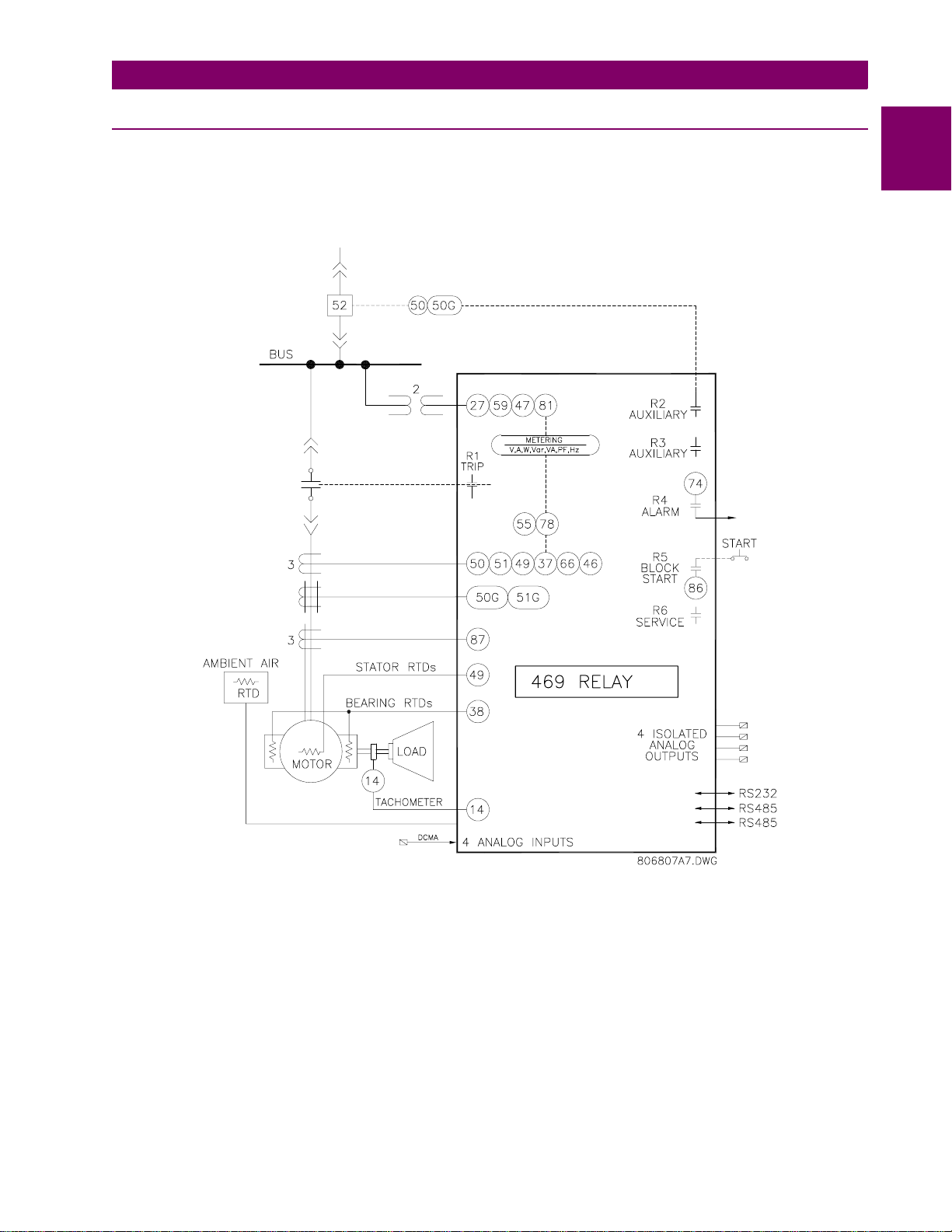
The 469 Motor Managemen t Relay is a micropro cessor ba sed rela y design ed for the prote ction and m anagement of medium and large hor sepower motors and driven equipment. Th e 469 is equipped with six output
relays for trips, alar ms, and start blocks. Motor protection, fault diagnosti cs, power metering, and RTU functions are integrated into one ec onomical drawout package. The single-line diagram below illus trates the 469
functionality using ANSI (American National Standards Institute) device numbers.
1
Figure 1–1: SINGLE LINE DIAGRAM
Typical applications include:
• Pumps • Fans • Compressors
•Mills •Shredders •Extruders
• Debarkers • Refiners • Cranes
• Conveyors • Chillers • Crushers
•Blowers
GE Power Management 469 Motor Management Relay 1-1
Page 14
1.1 OVERVIEW 1 INTRODUCTION
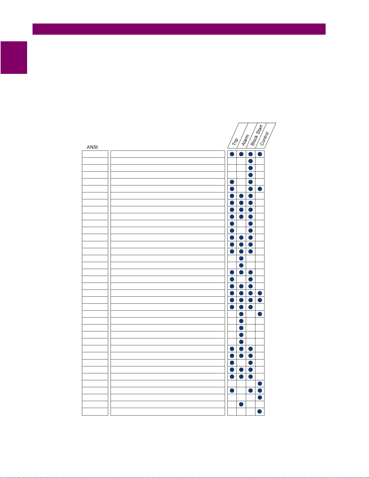
Some of the protection highlig hts are detailed here; a complete list is shown below. Four assignable digital
inputs may be configured for a number of different features including tachometer or generic trip and alarm with
1
a programmable name . The thermal model inc orporates unbalance bia sing, RTD feedback, and exponent ial
cooling. In addition to the 15 standard overload curves, there is a custom curve feature and a curve specifically
designed for the starting of high inertia loads, when the acceleration time exceeds the safe stall time. A second
overload curve is pr ovided for two-speed motors. Ground fau lts or earth leakage as low as 0.25 A may be
detected using the GE Power Management 50:0.025 Ground CT. CT inputs for phase differential protection are
also provided. The 12 RTD inputs provided may be individually field programmed for different RTD types. Voltage transformer inputs allow for numerous protec tion features based on vo ltage and power quantities. F our
4 to 20 mA analog inputs ma y be used for tripping and alarm ing on any transducer input such as vibration,
pressure, flow, etc.
51 Overload
86 Overload Lockout
66 Starts/Hour & Time Between Starts
Restart Block (Anti-Backspin Timer)
50 Short Circuit & Short Circuit Backup
Mechanical Jam
32
37
46 Current Unbalance
50G/51G Ground Fault & Ground Fault Backup
87 Differential
49 Stator RTD
38 Bearing RTD
27/59 Undervoltage/Overvoltage
47 Phase Reversal
81 Frequency
55/78 Power Factor
14 Speed Switch & Tachometer Trip
19 Reduced Voltage Start
48
Reverse Power
Undercurrent/Underpower
Acceleration
Other RTD & Ambient RTD
Open RTD Alarm
Short/Low RTD
Reactive Power
Analog Input
Demand Alarm: A kW kvar kVA
SR469 Self-Test, Service
Trip Coil Supervision
Welded Contactor
Breaker Failure
Remote Switch
Load Shed Switch
Pressure Switch
Vibration Switch
Incomplete Sequence (Reduced Voltage Start)
Remote Start/Stop
Over Torque
Forced Relay Operation
PROCTLA5.CDR
Figure 1–2: PROTECTION FEATURES
1-2 469 Motor Management Relay GE Power Management
Page 15

1 INTRODUCTION 1.1 OVERVIEW
Fault diagnostics are provided through pretrip data, event record, trace memory, and statistics. Prior to issuing
a trip, the 469 takes a snapshot of the measured parame ters and stores them with the cause of the trip. This
pre-trip data may be viewed using the key before the trip i s reset, or by accessing the
LAST TRIP DATA
actual values. The 469 event recorder stores up to 40 time and date stamped events including
NEXT
A1 STATUS /
the pre-trip data. Each time a trip occurs, the 469 stores a trace of 8 cycles pre-trip and 8 cycles post-trip for all
measured AC quantities . Trip counters record the number of occurrenc es of each type of trip. Minimum an d
maximum values for RTDs and analog inputs are also recorded. These features enable the operator to pinpoint
a problem quickly and with certainty.
Power metering is buil t into the 469 as a s tandard feature. The ta ble below outline s the metered param eters
available either through the front panel or communications ports.
The 469 is equipped with 3 fully functional and independent communications ports. The front panel RS232 port
may be used for 469 setpoint program ming , loca l interro gation or control , and upgradi ng of 469 fir mware. Th e
Computer RS485 port m ay be connecte d to a PLC, DCS , or PC based u ser interfac e program. The A uxiliary
RS485 port may be used for redundancy or simultaneous interrogat ion and/or control from a second PLC,
DCS, or PC software.
There are also four 4 to 20 mA or 0 to 1 mA (as specified with order) transducer outputs that may be assi gne d
to any measured parameter. The range of these outputs is scalable.
Additional features are outlined in the table below.
Table 1–1: METERING AND ADDITIONAL FEATURES
METERING ADDITIONAL FEATURES
Voltage Drawout case (for ease of maintenance/testing)
Current and amps demand Reduced voltage starting control for single transition
Real power, kW demand, kW power consumption Trip coil supervision
Apparent power and kVA demand Flash memory for easy firmware upda tes
Reactive power, kvar demand, kvar consumption/
generation
Frequency
Power Factor
RTD
Speed in RPM with a key phasor input
User-programmable analog inputs
1
GE Power Management 469 Motor Management Relay 1-3
Page 16

1.1 OVERVIEW 1 INTRODUCTION
1.1.2 ORDER INFORMATION
1
All 469 features are standard; there are no options. The phase CT secondaries, control power, and analog output range must be specified at the time of order. The 469 differential CT inputs are field programmable for CTs
with 1 A or 5 A secondaries. There are two gr ound CT inputs, one for the GE Power Manageme nt 50:0.025
core balance CT and one for a ground CT with a 1 A or 5 A secondary, also field programmable. The VT inputs
will accommodate VTs in either a delta or wye configuration. The output relays are always non-failsafe with the
exception of the serv ice relay. The 469PC software is p rovided with each unit. A metal dem o case may be
ordered for demonstration or testing purposes.
469
469 Basic unit
Additional access ories are listed in the following section.
• 469PC
DEMO:
•
SR 19-1 PANEL:
•
SR 19-2 PANEL:
•
SCI MODULE:
•
Phase CT:
•
HGF3, HGF5, HGF8:
•
Software:
***
P1
P5
LO
HI
A1
A20
Provided free with each relay
Metal Carry Case in which 469 unit may be mounted
Single cutout 19" panel
Dual cutout 19" panel
RS232 to RS485 converter box designed for harsh industrial environments
50, 75, 100, 150, 200, 250, 300, 350, 400, 500, 600, 750, 1000
For sensitive ground detection on high resistance grounded systems.
1A phase CT secondaries
5A phase CT secondaries
DC: 25-60 V; AC: 20-48 V @ 48-62 Hz
DC: 90-300 V; AC: 70-265 V @ 48-62 Hz
0-1 mA analog outputs
4-20 mA analog outputs
Figure 1–3: 469 ORDER CODES
1.1.3 OTHER ACCESSORIES
• 469
• 469
•
1" Collar:
3" Collar:
Optional Mounting Kit:
For shallow switchgear, reduces the depth of the relay by 1 #3/8"
For shallow switchgear, reduces the depth of the relay by 3"
Additional mounting support 1819-0030
1-4 469 Motor Management Relay GE Power Management
Page 17

1 INTRODUCTION 1.2 SPECIFICATIONS
1.2 SPECIFICATIONS 1.2.1 469 SPECIFICATIONS
POWER SUPPLY
Options: LO / HI (must be specified with order)
Range: LO: DC: 20 to 60 V DC
AC: 20 to 48 V AC at 48 to 62 Hz
HI: DC: 90 to 300 V DC
AC: 70 to 265 V AC at 48 to 62 Hz
Power: 45 VA (max), 25 VA typical
Proper operation time without supply voltage: 30 ms
PHASE CURRENT INPUTS
CT Primary: 1 to 5000 A
CT Secondary: 1 A or 5 A (must be specified with order)
Burden: Less than 0.2 VA at rated load
Conversion Range: 0.05 to 20 × CT
Accuracy: at < 2 x CT: ± 0.5% of 2 × CT
at ≥ 2 x CT: ± 1% of 20 × CT
CT Withstand: 1 second @ 80 × rated current
2 seconds @ 40 × rated current
continuous @ 3 × rated current
GROUND CURRENT INPUTS
CT Primary: 1 to 5000 A
CT Secondary: 1 A or 5 A (setpoint)
Burden: < 0.2 VA at rated load for 1 A or 5 A
< 0.25 VA for 50:0.025 @ 25 A
Conversion Range: 0.02 to 1 × CT primary Amps
Accuracy: ± 0.5% of 1 × CT for 5 A
± 0.5% of 5 × CT for 1 A
± 0.125 A for 50:0.025
CT Withstand: 1 second @ 80 × rated current
2 seconds @ 40 × rated current
continuous @ 3 × rated current
DIFFERENTIAL PHASE CURRENT INPUTS
CT Primary: 1 to 5000A
CT Secondary: 1 A or 5 A (setpoint)
Burden: Less than 0.2 VA at rated load
Conversion Range: 0.02 to 1 × CT
Accuracy: ±0.5% of 1 × CT for 5 A
±0.5% of 5 × CT for 1 A
CT Withstand: 1 second @ 80 × rated current
2 seconds @ 40 × rated current
continuous @ 3 × rated current
VOLTAGE INPUTS
VT Ratio: 1.00 to 150.00:1 in steps of 0.01
VT Secondary: 273 V AC (full scale)
Conversion Range: 0.05 to 1.00 × full scale
Accuracy: ±0.5% of full scale
Max. Continuous:280 V AC
Burden: > 500 kΩ
DIGITAL INPUTS
Inputs: 9 opto-isolated inputs
External Switch: dry contact < 800 Ω, or
open collector NPN transistor from sensor; 6 mA sinking from internal 4 KΩ pullup at 24 V DC with Vce < 4 V DC
469 Sensor Supply: +24 V DC at 20 mA max.
RTD INPUTS
RTDs: 3 wire type:100Ω Platinum (DIN.43760)
100 Ω Nickel
120 Ω Nickel
10 Ω Copper
RTD Sensing Current: 5mA
Isolation: 36 Vpk
(isolated with analog inputs and outputs)
Range: –50 to +250°C
Accuracy: ±2°C
Lead Resistance:25 Ω Max per lead for Pt and Ni type
3 Ω Max per lead for Cu type
No Sensor: >1000 Ω
Short/Low Alarm: < –50°C
TRIP COIL SUPERVISION
Applicable Voltage: 20 to 300 V DC / V AC
Trickle Current: 2 to 5 mA
ANALOG CURRENT INPUTS
Current Inputs: 0 to 1 mA, 0 to 20mA or 4 to 20 mA
(setpoint)
Input Impedance: 226 Ω ±10%
Conversion Range: 0 to 21 mA
Accuracy: ±1% of full scale
Type: passive
Analog Input Supply: +24 V DC at 100 mA max.
Response Time: ≤ 100 ms
COMMUNICATIONS PORTS
RS232 Port: 1, Front Panel, non-isolated
RS485 Ports: 2, Isolated together @ 36 V
Baud Rates: RS485: 300, 1200, 2400, 4800, 9600,
19200
RS232: 9600
Parity: None, Odd, Even
Protocol: Modbus® RTU / half duplex
pk
1
GE Power Management 469 Motor Management Relay 1-5
Page 18

1.2 SPECIFICATIONS 1 INTRODUCTION
ANALOG CURRENT OUTPUT
Type: Active
1
Range: 4 to 20 mA, 0 to 1 mA
(must be specified with order)
Accuracy: ±1% of full scale
4 to 20 mA maximu m load: 1200 Ω
0 to 1 mA maximum load: 10 kΩ
Isolation: 36 Vpk
(Isolated with RTDs and Analog Inputs)
4 Assignable Outputs:
phase A current
phase B current
phase C current
3 phase average current
ground current
phase AN (AB) voltage
phase BN (BC) voltage
phase CN (CA) voltage
3 phase average voltage
hottest stator RTD
hottest bearing RTD
hottest other RTD
RTD # 1 to 12
Power factor
3 phase Real power (kW)
3 phase Apparent power (kVA)
3 phase Reactive power (kvar)
Thermal Capacity Used
Relay Lockout Time
Current Demand
kvar Demand
kW Demand
kVA Demand
Motor Load
Torque
OVERLOAD / STALL PROTECTION /
THERMAL MODEL
Overload Curves:15 Standard Overload Curves, Custom
Curve, Voltage Dependent Custom
Curve for high inertia starting (all curves
time out against average phase current)
Curve Biasing: Phase Unbalance
Hot/Cold Curve Ratio
Stator RTD
Running Cool rate
Stopped Cool Rate
Line Voltage
Overload Pickup: 1.01 to 1.25 (for service factor)
Pickup Accuracy: as per Phase Current Inputs
Timing Accuracy: ±100 ms or ±2% of total time
Elements: Trip and Alarm
OUTPUT RELAYS
Configuration: 6 Electromechanical Form C
Contact Material: silver alloy
Operate Time: 10 ms
Max ratings for 100000 operations:
VOLTAGE MAKE/CARRY BREAK MAX.
DC
RESISTIVE
DC
INDUCTIVE
L/R=40ms
AC
RESISTIVE
AC
INDUCTIVE
P.F.=0.4
CONTINUOUS
30 V 10 A 30 A 10A 300 W
125 V 10 A 30 A 0.5 A 62.5 W
250 V 10 A 30 A 0.3 A 75 W
30 V 10 A 30 A 5A 150 W
125 V 10 A 30 A 0.25 A 31.3 W
250 V 10 A 30 A 0.15 A 37.5 W
120 V 10 A 30 A 10 A 2770 VA
250 V 10 A 30 A 10 A 2770 VA
120 V 10 A 30 A 4 A 480 VA
250 V 10 A 30 A 3 A 750 VA
0.2s
LOAD
TERMINALS
Low Voltage (A, B, C, D terminals): 12 AWG max.
High Voltage (E, F, G, H terminals): #8 ring lug, 10 AWG
wire standard
PHASE SHORT CIRCUIT
Pickup Level: 4.0 to 20.0 × CT primary in steps of 0.1
of any one phase
Time Delay: 0 to 1000 ms in steps of 10
Pickup Accuracy: as per Phase Current Inputs
Timing Accuracy: +50 ms
Elements: Trip
MECHANICAL JAM
Pickup Level: 1.01 to 3.00 × FLA in steps of 0.01 of any
one phase, blocked on start
Time Delay: 1 to 30 s in steps of 1
Pickup Accuracy: as per Phase Current Inputs
Timing Accuracy: ±0.5 s or ±0.5% of total time
Elements: Trip
UNDERCURRENT
Pickup Level: 0.10 to 0.95 × CT primary in steps of
0.01 of any one phase
Time Delay: 1 to 60 s in steps of 1
Block From Start: 0 to 15000 s in steps of 1
Pickup Accuracy: as per Phase Current Inputs
Timing Accuracy: ±0.5 s or ±0.5% of total time
Elements: Trip and Alarm
1-6 469 Motor Management Relay GE Power Management
Page 19

1 INTRODUCTION 1.2 SPECIFICATIONS
CURRENT UNBALANCE
Unbalance: I2/I1 if I
I
2/I1
Range: 0 to 100% UB in steps of 1
Pickup Level: 4 to 40% UB in steps of 1
Time Delay: 1 to 60 s in steps of 1
Pickup Accuracy: ±2%
Timing Accuracy: ±0.5 s or ± 0.5% of total time
Elements: Trip and Alarm
× I
avg
avg
> FLA
/FLA if I
avg
< FLA
GROUND INSTANTANEOUS
Pickup Level: 0.1 to 1.0 × CT primary in steps of 0.01
Time Delay: 0 to 1000 ms in steps of 10
Pickup Accuracy: as per Ground Current Input
Timing Accuracy: +50 ms
Elements: Trip and Alarm
PHASE DIFFERENTIAL INSTANTANEOUS
Pickup Level: 0.05 to 1.0 × CT primar y i n st eps of 0.01
of any one phase
Time Delay: 0 to 1000 ms in steps of 10
Pickup Accuracy: as per Phase Differential Current Inputs
Timing Accuracy: +50 ms
Elements: Trip
ACCELERATION TIMER
Pickup: transition of no phase current to > over-
load pickup
Dropout: when current falls below overload pickup
Time Delay: 1.0 to 250.0 s in steps of 0.1
Timing Accuracy: ±100 ms or ± 0.5% of total time
Elements: Trip
JOGGING BLOCK
Starts/Hour: 1 to 5 in steps of 1
Time Between Starts: 1 to 500 min.
Timing Accuracy: ±0.5 s or ± 0.5% of total time
Elements: Block
RESTART BLOCK
Time Delay: 1 to 50000 s in steps of 1
Timing Accuracy: ±0.5 s or ± 0.5% of total time
Elements: Block
RTD
Pickup: 1 to 250°C i n steps of 1
Pickup Hysteresis:2°C
Time Delay: 3 s
Elements: Trip and Alarm
UNDERVOLTAGE
Pickup Level:
Motor Starting: 0.60 to 0.99 × Rated in steps of 0.01
Motor Running:0.60 to 0.99 × Rated in steps of 0.01
of any one phase
Time Delay: 0.1 to 60.0 s in steps of 0.1
Pickup Accuracy: as per Voltage Inputs
Timing Accuracy: <100 ms or ±0.5% of total time
Elements: Trip and Alarm
OVERVOLTAGE
Pickup Level: 1.01 to 1.10 × Rated in steps of 0.01 of
any one phase
Time Delay: 0.1 to 60.0 s in steps of 0.1
Pickup Accuracy: as per Voltage Inputs
Timing Accuracy: ±100 ms or ±0.5% of total time
Elements: Trip and Alarm
VOLTAGE PHASE REVERSAL
Configuration: ABC or ACB phase rotation
Timing Accuracy: 500 to 700 ms
Elements: Trip
FREQUENCY
Required Voltage:> 30% of full scale in Phase A
Overfrequency Pickup: 25.01 to 70.00 in steps of 0.01
Underfrequency Pickup: 20.00 to 60.00 in steps of 0.01
Accuracy: ±0.02 Hz
Time Delay: 0.1 to 60.0 s in steps of 0.1
Timing Accuracy: <100 ms or ±0.5% of total time
Elements: Trip and Alarm
REDUCED VOLTAGE START
Transition Level: 25 to 300% FLA in steps of 1
Transition Time: 1 to 250 s in steps of 1
Transition Control: Current, Timer, Current and Timer
REMOTE SWITCH
Configurable: Assignable to Digital Inputs1 to 4
Timing Accuracy: 100 ms max.
Elements: Trip and Alarm
SPEED SWITCH
Configurable: Assignable to Digital Inputs1 to 4
Time Delay: 1.0 to 250.0 s in steps of 0.1
Timing Accuracy: 100 ms max.
Elements: Trip
LOAD SHED
Configurable: Assignable to Digital Inputs1 to 4
Timing Accuracy: 100 ms max.
Elements: Trip
1
GE Power Management 469 Motor Management Relay 1-7
Page 20

1.2 SPECIFICATIONS 1 INTRODUCTION
PRESSURE SWITCH
Configurable: Assignable to Digital Inputs1 to 4
1
Time Delay: 0.1 to 100.0 s in steps of 0.1
Block From S tart: 0 to 5000 s in steps of 1
Timing Accuracy: ±100 ms or ±0.5% of total time
Elements: Trip and Alarm
VIBRATION SWITCH
Configurable: Assignable to Digital Inputs1 to 4
Time Delay: 0.1 to 100.0 s in steps of 0.1
Timing Accuracy: ±100 ms or ±0.5% of total time
Elements: Trip and Alarm
DIGITAL COUNTER
Configurable: Assignable to Digital Inputs1 to 4
Counting Frequency: ≤ 50 times a second
Range: 0 to 1 000 000 000
Elements: Alarm
TACHOMETER
Configurable: Assignable to Digital Inputs1 to 4
RPM Measurement: 100 to 7200 RPM
Duty Cycle of Pulse: > 10%
Elements: Trip and Alarm
GENERAL PURPOSE SWITCH
Configurable: Assignable Digital Inputs1 to 4
Time Delay: 0.1 to 5000.0 s in steps of 0.1
Block From S tart: 0 to 5000 s in steps of 1
Timing Accuracy: ±100 ms or ±0.5% of total time
Elements: Trip and Alarm
POWER FACTOR
Range: 0.01 lead or lag to 1.00
Pickup Level: 0.99 to 0.05 in steps of 0.01, Lead & Lag
Time Delay: 0.2 to 30.0 s in steps of 0.1
Block From S tart: 0 to 5000 s in steps of 1
Pickup Accuracy: ±0. 02
Timing Accuracy: ±100 ms or ±0.5% of total time
Elements: Trip and Alarm
3 PHASE REAL POWER
Range: 0 to ±99999 kW
Underpower Pickup: 1 to 25000 kW in steps of 1
Time Delay: 1 to 30 s in steps of 1
Block From Start: 0 to 15000 s in steps of 1
Pickup Accuracy:
±1% of × 2 × CT × VT × VT
±1.5% of × 20 × CT × VT × VT
3
3
full scale
full scale
at I
avg
at I
< 2 × CT
> 2 × CT
avg
Timing Accuracy: ±0.5 s or ±0.5% of total time
Elements: Trip and Alarm
3 PHASE APPARENT POWER
Range: 0 to 65535 kVA
Accuracy:
±1% of × 2 × CT × VT × VT
±1.5% of × 20 × CT × VT × VT
3
3
full scale
full scale
@ I
avg
@ I
< 2 × CT
> 2 × CT
avg
3 PHASE REACTIVE POWER
Range: 0 to ±99999 kvar
Pickup Level: ±1 to 25000 kvar in steps of 1
Time Delay: 0.2 to 30.0 s in steps of 0.1
Block From Start: 0 to 5000 s in steps of 1
Pickup Accuracy:
±1% of × 2 × CT × VT × VT
±1.5% of × 20 × CT × VT × VT
3
3
full scale
full scale
@ I
avg
@ I
< 2 × CT
> 2 × CT
avg
Timing Accuracy: ±100ms or ± 0.5% of total time
Elements: Trip and Alarm
OVER TORQUE
Pickup Level: 1.0 to 999999.9 Nm/ft·lb in steps of 0.1;
torque unit is selectable under torque
setup
Time Delay: 0.2 to 30.0 s in steps of 0.1
Pickup Accuracy: ±2.0%
Time Accuracy: ±100 ms or 0.5% of total time
Elements: Alarm (INDUCTION MOTORS ONLY)
METERED REAL POWER CONSUMPTION
Description: Continuous total of real power
consumption.
Range: 0 to 2000000.000 MW·hours.
Timing Accuracy: ±0.5%
Update Rate: 5 seconds
METERED REACTIVE POWER CONSUMPTION
Description: Continuous total of reactive power
consumption.
Range: 0 to 2000000.000 Mvar·hours
Timing Accuracy: ±0.5%
1-8 469 Motor Management Relay GE Power Management
Page 21

1 INTRODUCTION 1.2 SPECIFICATIONS
FUSE
Hi-Volt:
Current Rating: 2 A
Type: 5 × 20mm Slo-Blo Littelfuse
High Breaking Capacity
Model#: 215002
Lo-Volt:
Current Rating:3.15 A
Type: 5 × 20mm Slo-Blo Littelfuse
High Breaking Capacity
Model#: 2153.15
External fuse must be used if the supply voltage exceeds 250 V.
NOTE
DEMAND
Metered Values: Max imum Phase Current
3 Phase Real Power
3 Phase Apparent Power
3 Phase Reactive Power
Measurement Type: Rollin g Demand
Demand Interval: 5 to 90 minutes in steps of 1
Update Rate: 1 minute
Elements: Alarm
OTHER FEATURES
Pre-Trip Data
Event Recorder
Trace Memory
Starter Failure
Fault Simulation
VT Failure
ENVIRONMENT
Ambient Operating Temperature: –40°C to +60°C
Ambient Storage Temperature: –40°C to +80°C
Humidity: Up to 90%, noncondensing.
Altitude: Up to 2000 m
Pollution Degree: 2
It is recommended that the 469 be powered up
at least once per year to prevent deterioration
NOTE
of electrolytic capacitors in the power supply.
PRODUCTION TESTS
Thermal Cycling: Operational test at ambient, reducing to
–40°C and then increasing to 60°C
Dielectric Strength: 2.0 kV for 1 minute from relays, CTs,
VTs, power supply to Safety Ground
DO NOT CONNECT FILTER GROUND TO
SAFETY GROUND DURING TEST!
WARNING
TYPE TESTS
Dielectric Strength: Per IEC 255-5 and ANSI/IEEE C37.90
2.0 kV for 1 minute from relays, CTs,
VTs, power supply to Safety Ground
DO NOT CONNECT FILTER GROUND TO
SAFETY GROUND DURING TEST
WARNING
Insulation Resistance: IEC255-5 500 V DC, from relays,
CTs, VTs, power supply to Safety
Ground
DO NOT CONNECT FILTER GROUND TO
SAFETY GROUND DURING TEST
WARNING
Transients: ANSI C37.90.1 Oscillatory (2.5kV/1MHz)
ANSI C37.90.1 Fast Rise (5kV/10ns)
Ontario Hydro A-28M-82
IEC255-4 Impulse/High Frequency Dis-
turbance, Class III Level
Impulse Test: IEC 255-5 0.5 Joule 5 kV
RFI: 50 MHz/15 W Transmitter
EMI: C37.90.2 Electromagnetic Interference
@150 MHz and 450 MHz, 10 V/m
Static: IEC 80 1-2 Static Discharge
Humidity: 95% non-condensing
Temperature: –40°C to +60°C ambient
Environment: IEC 68-2-38 Temperature/Humidity
Cycle
Vibration: Sinusoidal Vibration 8.0 g for 72 hrs.
PACKAGING
Shipping Box: 12” × 11” × 10” (W × H × D)
30.5cm × 27.9cm × 25.4cm
Shipping Weight: 17 lbs Max / 7.7 kg
1
BATTERY BACKUP
Used only when no control power to relay.
Life expectancy is ≥ 10 ye ars wi th n o co ntro l po wer to relay
CASE
Fully drawout (automatic CT shorts)
Seal provision
Dust tight door
Panel or 19" rack mount
IP Class: IP20-X
CERTIFICATION
ISO: Manufactured under an ISO9001 registered system.
UL: UL approved
CSA: CSA approved
CE: Conforms to EN 55011/CISPR 11, EN 50082-2
Conforms to IEC 947-1,1010-1
GE Power Management 469 Motor Management Relay 1-9
Page 22

Page 23

2 INSTALLATION 2.1 MECHANICAL
2 INSTALLATION 2.1 MECHANICAL 2.1.1 DESCRIPTION
The 469 is packaged in the standard GE Power Management SR series arrangement, which consists of a drawout unit and a co mpanion fixed case. The case provides mechanical protection to the unit and is used to
make permanent con nections to al l external e quipment. The only electric al components mounted in the case
are those required to c onnect the unit to the external wiring. Connections in th e case are fitted with mechanisms required to al low the sa fe r em ov al of th e rel ay uni t fr om an ene rg ized panel (for example, automatic CT
shorting). The unit is mechanically held in the case by pins on the locking handle that cannot be fully lowered to
the locked position unt il the elec trical con nections ar e complete ly mated. A ny 469 can b e install ed in any 46 9
case, except for c ustom man ufactured un its that a re clearl y identifie d as suc h on both case and unit, and are
equipped with an index pin keying mechanism to prevent incorrect pairings.
No special ventilatio n requirements need to be observed duri ng the installation of the unit. The 469 c an be
cleaned with a damp cloth.
2
Figure 2–1: DIMENSIONS
To prevent unauthorized re moval of th e drawou t unit, a wire lead seal ca n be ins talled in the s lot provi ded on
the handle. With this seal in place, the drawout unit cannot be removed. A passcode or setpoint access jumper
can be used to prevent entry of setpoints but allow monitoring of actual values. If access to the front panel controls must be restricted, a separate seal can be installed on the cover to prevent it from being opened.
Hazard may result if the product is not used for its intended purpose.
WARNING
Figure 2–2: SEAL ON DRAWOUT UNIT
GE Power Management 469 Motor Management Relay 2-1
Page 24

2.1 MECHANICAL 2 INSTALLATION
2.1.2 PRODUCT IDENTIFICATION
Each 469 unit and c ase are e qui ppe d wi th a p er man ent lab el . T his l abe l i s ins tal led on t he l eft s i de (when facing the front of the relay) of both unit and case. The case label details which units can be installed.
2
The case label details the following info r mation:
• MODEL NUMBER
• MANUFACTURE DATE
• SPECIAL NOTES
The unit label details the following information:
• MODEL NUMBER
•TYPE
• SERIAL NUMBER
• MANUFACTURE DATE
• PHASE CURRENT INPUTS
• SPECIAL NOTES
• OVERVOLTAGE CATEGORY
• INSULATION VOLTAGE
• POLLUTION DEGREE
• CONTROL POWER
• OUTPUT CONTACT RATING
Figure 2–3: CASE AND UNIT IDENTIFICATION LABELS
2-2 469 Motor Management Relay GE Power Management
Page 25
2 INSTALLATION 2.1 MECHANICAL
2.1.3 INSTALLATION
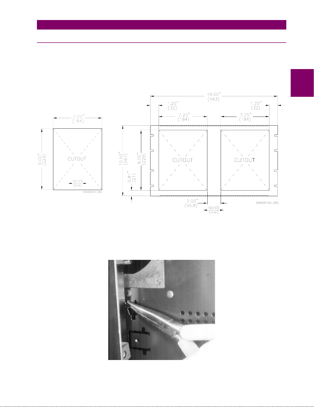
The 469 case, alone or adj acen t to anothe r SR ser ies u nit, ca n be instal led in the p anel of a stand ard 19-i nch
rack (see the diagr am below for panel cutout d imensions). Provision must b e made when mounting for the
front door to swing open without interference to, or from, adjacent equipment. Normally the 469 unit is mounted
in its case when shipped fr om the fa ctory, and should be removed befo re mou nting the case in the supp ortin g
panel. Unit withdrawal is described in the next section.
Double Cutout Panel
Single Cutout Panel
2
Figure 2–4: SINGLE AND DOUBLE 469 CUTOUT PANELS
After the mounting hole in the panel has been prepared, slide the 469 case into the panel from the front. Applying firm pressure on the front to ensur e the front be zel fits snugl y against the fr ont of the panel , bend out the
pair of retaining tabs (to a horizontal po sition) from each side of the case as shown below. The case is no w
securely mounte d, read y for panel wiring. If additional sup port i s de si red, the SR optional mounting kit may b e
ordered.
Figure 2–5: BEND UP MOUNTING TABS
GE Power Management 469 Motor Management Relay 2-3
Page 26

2.1 MECHANICAL 2 INSTALLATION
2.1.4 UNIT WITHDRAWAL AND INSERTION
TURN OFF CONTROL POWER BEFORE DRAWING OUT OR RE-INSERTING THE RELAY TO
PREVENT MALOPERATION!
CAUTION
2
CAUTION
To remove the unit from the case:
1. Open the cover by grasping the center of the right side and then pulli ng the cover, which will rotate about
2. Release the locking latch, located below the locking handle, by pressing upward on the latch with the tip of
If an attempt is made to install a unit into a non-matching case, the mechanica l key will prevent full insertion of the unit. Do not apply strong force in the following step or damage may
result.
the hinges on the left.
a screwdriver.
Figure 2–6: PRESS LATCH TO DISENGAGE HANDLE
3. While holding the latch raised, grasp the locking handle in the center and pull firmly, rotating the handle up
from the bottom of the unit until movement ceases.
Figure 2–7: ROTATE HANDLE TO STOP POSITION
2-4 469 Motor Management Relay GE Power Management
Page 27

2 INSTALLATION 2.1 MECHANICAL
4. Once the handle is released from the locking mechan ism, the unit ca n freely slide ou t of the case whe n
pulled by the handle. It may sometimes be necessary to adjust the handle position slightly to free the unit.
2
Figure 2–8: SLIDE UNIT OUT OF CASE
To insert the unit into the case:
1. Raise the locking handle to the highest position.
2. Hold the unit immediately in front of the case and align the rolling guide pins (near the hinges of the locking
handle) to the guide slots on either side of the case.
3. Slide the unit into the case until the guide pi ns on th e unit have engaged the guid e slots on either si de of
the case.
4. Grasp the locking handle fr om the ce nter and pre ss down firm ly, rotating the handle from the ra ised posi-
tion toward the bottom of the unit.
5. When the unit is fully inserted, the latch will be heard to click, locking the handle in the final position.
No special ventilation requirements need to be observed during the installation of the unit.
The unit does not require cleaning.
CAUTION
GE Power Management 469 Motor Management Relay 2-5
Page 28
2
2.1 MECHANICAL 2 INSTALLATION
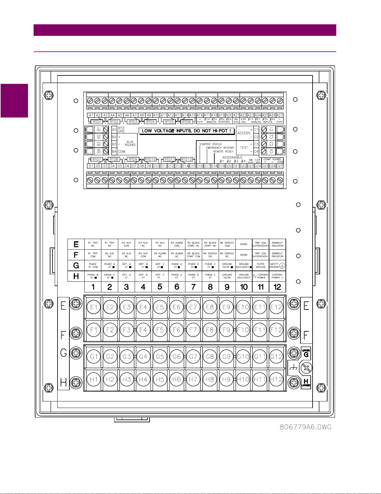
2.1.5 TERMINAL LOCATIONS
Figure 2–9: TERMINAL LAYOUT
2-6 469 Motor Management Relay GE Power Management
Page 29

2 INSTALLATION 2.1 MECHANICAL
T able 2–1: 469 TERMINAL LIST
A01 RTD #1 HOT D21 ASSIGNABLE SW. 03
A02 RTD #1 COMPE NSATION D22 ASSIGNABLE SW. 04
A03 RTD RETURN D23 SWITCH COMMON
A04 RTD #2 COMPENSATION D24 SWITCH +24 V DC
A05 RTD #2 HOT D25 COMPUTER RS485 +
A06 RTD #3 HOT D26 COMPUTER RS485 –
A07 RTD #3 COMPENSATION D27 COMPUTER RS485 COMMON
A08 RTD RETURN E01 R1 TRIP NC
A09 RTD #4 COMPE NSATION E02 R1 TRIP NO
A10 RTD #4 HOT E03 R2 AUXILIARY COMMON
A11 RTD #5 HOT E04 R3 AUXILIARY NC
A12 RTD #5 COMPE NSATION E05 R3 AUXILIARY NO
A13 RTD RETURN E06 R4 ALARM COMMON
A14 RTD #6 COMPENSATION E07 R5 BLOCK START NC
A15 RTD #6 HOT E08 R5 BLOCK START NO
A16 A NALO G OUT COMMON – E09 R6 SERVICE COMMON
A17 ANALOG OUT 1 + E10 not used
A18 ANALOG OUT 2 + E11 COIL SUPERVISION +
A19 ANALOG OUT 3 + E12 469 DRAWOUT INDICATOR
A20 ANALOG OUT 4 + F01 R1 TRIP COMMON
A21 ANALOG SHIELD F02 R2 AUXILIARY NO
A22 ANALOG INPUT 24 V DC POWER SUPPLY + F03 R2 AUXILIARY NC
A23 ANALOG INPUT 1 + F04 R3 AUXILIARY COMMON
A24 ANALOG INPUT 2 + F05 R4 ALARM NO
A25 ANALOG INPUT 3 + F06 R4 ALARM NC
A26 ANALOG INPUT 4 + F07 R5 BLOCK START COMMON
A27 A NALOG INPUT COMMON – F08 R6 SERVICE NO
B01 RTD SHIELD F09 R6 SERVICE NC
B02 AUXILIARY RS485 + F10 not used
B03 AUXILIARY RS485 – F11 COIL SUPERVISION –
B04 A UXILIARY RS485 COMMON F12 469 DRAWOUT INDICATOR
C01 ACCESS + G01 PHASE VT NEUTRAL
C02 ACCESS – G02 PHASE A VT
C03 469 UNDER TEST + G03 DIFFERENTIAL A CT
C04 469 UNDER TEST – G04 DIFFERENTIAL B CT
D01 RTD #7 HOT G05 DIFFERENTIAL C CT
D02 RTD #7 COMPENSATION G06 PHASE A CT
D03 RTD RETURN G0 7 PHASE B CT
D04 RTD #8 COMPENSATION G08 PHASE C CT
D05 RTD #8 HOT G09 1A/5A GROUND CT
D06 RTD #9 HOT G10 50:0.025 GROUND CT
D07 RTD #9 COMPENSATION G11 FILTER GROUND
D08 RTD RETURN G1 2 SAFETY GROUND
D09 RTD #10 COMPENSATION H01 PHASE B VT
D10 RTD #10 HOT H02 PHASE C VT
D11 RTD #11 HOT H03 DIFFEREN TIAL A CT
D12 RTD #11 COMPENSATION H04 DIFFERENTIAL B CT
D13 RTD RETURN H05 DIFFERENTIAL C CT
D14 RTD #12 COMPENSATION H06 PHASE A CT
D15 RTD #12 HOT H07 PHASE B CT
D16 STARTER STATUS H08 PHASE C CT
D17 EMERGENCY RESTART H09 1A/5A GROUND CT
D18 REM OT E RESET H10 50:0.025 GROUND CT
D19 ASSIGNABLE SW. 01 H11 CONTROL POWER –
D20 ASSIGNABLE SW. 02 H12 CONTROL POWER +
•
•
•
•
•
•
•
•
•
•
•
2
GE Power Management 469 Motor Management Relay 2-7
Page 30

2.2 ELECTRICAL 2 INSTALLATION
2.2 ELECTRICAL 2.2.1 TYPICAL WIRING DIAGRAM
2
Figure 2–10: TYPICAL WIRING DIAGRAM
2-8 469 Motor Management Relay GE Power Management
Page 31

2 INSTALLATION 2.2 ELECTRICAL
2.2.2 TYPICAL WIRING
A broad range of 469 applications are available. Although it is not possible to present typical connections for all
possible schemes, this section will cover the inte rconnections of instrument tr ansformer inputs, other inp uts,
outputs, communicat ions, and grounding. See Figure 2–9: TERMINAL LAYOUT on page 2–6 and Table 2–1:
469 TERMINAL LIST on page 2–7 for terminal arrangement.
2.2.3 CONTROL POWER
The
does not match, damage to the unit may occur!
CAUTION
The order code from th e te r min al la bel on th e s id e o f th e d ra wout uni t s pe cif ie s the nom in al co ntr ol v olt age as
one of the following:
LO: 20 to 60 V DC
20 to 48 V AC
Ensure applied control voltage and rated voltag e on drawout case termina l label match . For example, the HI
power supply will work with any DC voltage from 90 to 300 V, or AC voltage from 70 to 265 V. The internal fuse
may blow if the applied voltage exceeds this range.
control power must match the installed switching power supply. If the applied voltage
469
HI: 90 to 300 V DC
70 to 265 V AC
2
Figure 2–11: CONTROL POWER CONNECTION
Extensive filtering a nd transient protecti on are built into the 469 to ensure proper oper ation in h arsh indus trial
environments. Transient energ y must be conducted back to the source through the f ilter ground terminal. A
separate safety ground terminal is provided for hi-pot testing.
All grounds MUST be hooked up for normal operation regardless of control power supply
type.
WARNING
GE Power Management 469 Motor Management Relay 2-9
Page 32

2.2 ELECTRICAL 2 INSTALLATION
2.2.4 PHASE CURRENT INPUTS
The 469 has three chan nel s fo r phas e c urr ent i npu ts , each wi th a n is ol ati ng tran sf or mer. There are no inter nal
ground connections on the current inputs. If the unit is withdrawn , each phase CT ci rcuit is shorted by automatic mechanisms on the 469 cas e. The phas e CTs should be chosen so the FLA is no less than 50% of th e
rated phase CT prim ary. Ideally, the phase CT primary should be chos en such that the FLA is 100% of the
phase CT primary or slightly less, nev er more. This will ensure maximum ac curacy for the cu rrent measure-
2
ments. The maximum phase CT primar y cu rren t is 5000 A.
The 469 correctly mea sures up to 20 times the phas e current nominal rating. Sin ce the conversion range is
large, 1 A or 5 A CT secondaries must be specified at the time of order to ensure the appro priate interpos ing
CT is installed in the unit. The chosen CTs must be capable of drivi ng the 469 p hase CT burd en (see Sec tion
1.2: SPECIFICATIONS on page 1–5 for ratings).
Ver ify that th e
nections of the connected CTs. Unmatched CTs may result in equipment damage or inade-
CAUTION
See Appendix B.1: TWO-PHASE CT CONFIGURATION on page B–1 for 2-phase CT information.
The 469 has a dual primary isolating transformer for ground CT connection. There are no internal ground connections on the gr ound current inputs. The ground CT c ircuits are shorted by automatic mech anisms on the
469 case if the uni t i s wit hdr awn . The 1 A / 5 A tap is used either for ze ro -seq uen ce /co re ba lan ce ap pl ic ati ons
or residual ground con nections where the summation of the three phase current CTs is passed through the
ground current input (s ee the figure below). The ma ximum ground CT pr imary current is 5000 A for the 1 A /
5 A tap. Alternatively, the 50:0.025 ground CT inpu t has been d esigned f or sensiti ve ground cu rrent de tection
on high resistance grounded systems wher e the GE Power Mana gement 50:0.025 core b alance CT is to be
used. For example, in mining applications where earth leakage current must be measured for personnel safety,
primary ground cu rren t as low as 0 .25 A may be detected with the GE Power Mana gem ent 50:0 .025 CT . Only
one ground CT input tap should be used on a given unit.
quate protection. Polarity of the phase CTs is critical for Negative Sequence Unbalance
calculation, power measurement, and residual ground current detection (if used).
nominal phase current of 1 A or 5 A matches the secondary rating and con-
469
2.2.5 GROUND CURRENT INPUT
Figure 2–12: RESIDUAL GROUND CT CONNECTION
2-10 469 Motor Management Relay GE Power Management
Page 33

2 INSTALLATION 2.2 ELECTRICAL
The 469 measures up to 5 A secondary current if the 1 A / 5 A tap is used. Since the conversion range is relatively small, the 1 A or 5 A option is field programmable. Proper selection of this setpoint ensures proper reading of primary gr ound c urr ent. T he 1 A / 5 A gr ou nd CT c ho sen m us t b e c ap abl e of driv in g t he 469 ground CT
burden (see Section 1.2: SPECIFICATIONS on page 1–5). The 469 measures up to 2 5 A of primary groun d
current if this tap is used in conjunction with the GE Power Management core balance CT.
The zero-sequence connection is recommended. Unequal saturation of CTs, size and location
of motor, resistance of power system and motor core saturation density, etc., may cause false
NOTE
NOTE
The exact placement of a zero-sequence CT to detect only ground fault current is shown below. If the core balance CT is placed ov er s hie ld ed c ab le, ca pac it iv e c ou pli ng of p has e c urr ent in to th e c ab le shield during motor
starts may be detected as ground current unless the shield wire is also passed through the CT window.
Twisted pair cabling on the zero-sequence CT is recommended.
readings in the residually connected GF circuit.
Only one ground input should be wired – the other input should be unconnected.
2
SHIELDED CABLE
Figure 2–13: CORE BALANCE GROUND CT INSTALLATION
UNSHIELDED CABLE
GE Power Management 469 Motor Management Relay 2-11
Page 34

2.2 ELECTRICAL 2 INSTALLATION
2.2.6 DIFFERENTIAL CURRENT INPUTS
The 469 has three channe ls for differential current inputs, each with an is olating transformer. There are no
internal ground co nnection s on the current i nputs. Ea ch differenti al CT circ uit is sho rted by aut omatic m echanisms on the 469 case if the unit is withdrawn. The maximum differential CT primary current is 5000 A.
The 469 measures up to 5 A secondary current for the differential CT inputs. Since the conversion range is relatively small, the 1 A or 5 A option is field programmable. Proper selection of this setpoint ensures proper read-
2
ing of primary phas e differential curren t. The 1 A / 5 A differential CT chosen must b e capable of drivin g the
469 differential CT burden (see Section 1.2: SPECIFICATIONS on page 1–5 for ratings).
The differential CT s may be core balance as shown in the first figure below. Alternatively , the summation of two
CTs per phase into the d ifferentia l i npu t wi ll p rovi de a l arge r zo ne of p r otec tion. If the summation of two CTs is
used, observation of CT polarity is important. The summation m ethod may also be implemented usin g the
phase CTs as shown below. They will have to have the same CT ratio.
Figure 2–14: CORE BALANCE METHOD
WITHOUT PHASE CTs WITH PHASE CTs
Figure 2–15: SUMMATION METHOD
2-12 469 Motor Management Relay GE Power Management
Page 35

2 INSTALLATION 2.2 ELECTRICAL
2.2.7 VOLTAGE INPUTS
The 469 has three chan nels for AC voltage inputs , each with an isolating transf ormer. There are no internal
fuses or ground connec tions on the volta ge inputs. The maximum V T ratio is 150.00:1. T he two VT connections are open delta (s ee Figure 2–10: TYPICAL W IRING DIAGRAM on page 2–8) or wye (see below). T he
voltage channels are connected in wye internally, which means that the jumper shown on the delta-source connection of the TYPICAL WIRING DIAGRAM, between the phase B input and the 469 neutral terminal, must be
installed for open delta VTs.
Polarity of the VTs is critical for correct power measurement and voltage phase reversal operation.
A 1 A fuse is typically used to protect the inputs.
2
Figure 2–16: WYE VOLTAGE TRANSFORMER CONNECTION
2.2.8 DIGITAL INPUTS
There are 9 digital inputs designed for dry contact connections only. Two of the digital inputs (Access and Test)
have their own comm on termi nal; th e bal ance of th e d igital i nputs share o ne com mon te rmin al (see Fig ure 2–
10: TYPICAL WIRING DIAGRAM on page 2–8).
In addition, the + 24 V DC swi tc h s up ply is br ou ght out for c on tro l powe r of an inductive or capacitive pr oximity
probe. The NPN transistor output could be taken to one of the assignable digital inputs configured as a counter
or tachometer. Refer to Section 1.2: SPECIFICATIONS on page 1–5 for maximum current draw from the
+24 V DC switch supply.
DO NOT INJECT VOLTAGES TO DIGITAL INPUTS. DRY CONTACT CONNECTIONS ONLY.
CAUTION
GE Power Management 469 Motor Management Relay 2-13
Page 36

2.2 ELECTRICAL 2 INSTALLATION
2.2.9 ANALOG INPUTS
The 469 provides terminals for four 0 to 1mA, 0 to 20mA, or 4 to 20mA current input signals (field programmable). This current sig nal can be used to monitor exter nal quantities such as v ibration, pressure, or flow. T he
four inputs share one common return. Polarity of these inputs must be observed for proper operation The analog input circuitry is is olated as a group with the analog output circuitry and the RTD circuitry. Only one ground
reference should be u sed for the three c ircuits. Transorbs limit th is isolation to ±36 V with respec t to the 469
2
safety ground.
In addition, the +24 V DC analo g input supply is brought o ut for control power of loop power ed transducers.
Refer to Section 1.2: SPECIFICATIONS on page 1–5 for maximum current draw from this supply.
Figure 2–17: LOOP POWERED TRANSDUCER CONNECTION
2.2.10 ANALOG OUTPUTS
The 469 provides 4 analog outp ut channels whi ch may be ordered to prov ide a full-sc ale range of e ither 0 to
1 mA (into a maximum 10 kΩ impedance) or 4 to 20 mA (into a maximum 1200Ω impedance). Each cha nnel
can be configured to provide full-scale output sensitivity for any range of any measured parameter.
As shown in Figure 2–10: TYPICAL WIRING DIAGRAM on page 2–8, these outputs share one common
return. Polarity of thes e outputs must be obs erved for proper o peration. Shie lded cable should b e used, with
only one end of the shield grounded, to minimize noise effects.
The analog output circuitry is isolated as a group with the Analog Input circuitry and the RTD circuitry. Only one
ground reference should be used for the three circuits. Transorbs limit this isolation to ±36 V with respect to the
469 safety ground.
If a voltage output is requir ed, a burden resistor must be connected at the input of the SCA DA measuring
device. Ignoring the input impedance of the input,
scale is required to corr espond to 1 m A,
R
= 5 V / 0.020 A = 250 Ω.
load
R
load
R
=
V
load
= 5 V / 0.001 A = 5000Ω. For 4 to 20 mA, this resistor would be
full scale
/
I
. For 0 to 1 mA, for example, if 5 V full
max
2-14 469 Motor Management Relay GE Power Management
Page 37

2 INSTALLATION 2.2 ELECTRICAL
2.2.11 RTD SENSOR CONNECTIONS
a) DESCRIPTION
The 469 monitors up to 12 RTD inputs for Stator, Bearing, Ambient, or Other temperature monitoring. The type
of each RTD is field programmable as 10 0Ω Platinum (DIN 43760), 100Ω Nickel, 120Ω Nickel, or 10Ω Copper. RTDs must be three wire type. Every two RTDs shares a common return.
The 469 RTD circuitry c ompensates for lead resistance, pr ovided that each of the three lea ds is the same
length. Lead resistance should not exceed 25Ω per lead for platinum/nickel type RTDs or 3Ω per lead for copper type RTDs. Shielded cabl e should be used to prevent noise picku p in the industrial environment. RTD
cables should be kept close to gr ounded metal ca sings and away from areas of high elec tromagnetic or radio
interference. RTD leads should not be run adjacent to or in the same conduit as high current carrying wires.
RELAY
CHASSIS
GROUND
SHIELD
HOT
COMPENSATION
RTD #1
RTD SENSING
RETURN
469
B1
A1
A2
A3
MOTOR
STARTER
RTD
TERMINALS
IN MOTOR
STARTER
3 WIRE SHIELDED CABLE
Route cable in separate conduit from
current carrying conductors
Maximum total lead resistance
25 ohms (Platinum & Nickel RTDs)
3 ohms (Copper RTDs)
RTD TERMINALS
AT MOTOR
MOTOR
RTD IN
MOTOR
STAT OR
OR
BEARING
806819A5.CDR
Figure 2–18: RTD WIRING
IMPORTANT: The RTD circuitry is isolated as a group with the Analog Input circuitry and the
Analog Output circuitry. Only one ground reference should be used for the three circuits.
NOTE
Transorbs limit this isolation to ±36 V with respect to the 469 safety ground.
2
GE Power Management 469 Motor Management Relay 2-15
Page 38

2.2 ELECTRICAL 2 INSTALLATION
b) REDUCED RTD LEAD NUMBER APPLICATION
The 469 requires three le ads to b e br ou ght b ac k from eac h RTD: Hot, Return and Compensation. This can be
quite expensive. It is however pos sible to reduce the num ber of leads requi red to 3 for the first RTD and 1 for
each successive RTD. Refer to the figure below for wiring configuration for this application.
2
Figure 2–19: REDUCED WIRING RTDS
The Hot line would have to be run as usual for each RTD. The Compensation and Return leads, however, need
only be run for the first RTD. At the motor RTD terminal box, the RTD Return leads must be jumpered together
with as short as possible jumpers. The Compensation leads must be jumpered together at the 469.
Note that an error is produ ced on each RTD equal to the voltage drop acros s the jumper on the RTD return .
This error increases with each successive RTD added.
V
=
=
= V
= V
V
RTD1
V
RTD2
RTD3
RTD4
+
V
J3
+ V
+ V
J3
+ VJ3+ V
J4
J4
+ V
, etc....
J5
RTD1
V
RTD2
V
RTD3
V
RTD4
This error is dir ectly depe ndent on th e length and gauge of the wir e used for the jum pers an d any error introduced by a poor connecti on. For RTD types other than 10Ω Copper, the error introduced by the jumpers is
negligible.
This RTD wiring technique reduces the cost of wiring, however, the following disadvantages must be noted:
1. There will be an error in temperature readings due to lead an d connection resistan ces. This techniq ue is
NOT
recommended for 10Ω Copper RTDs.
2. If the RTD Return lead to the 469 or any of the jumpers break, all RTDs from the point of the break will read
open.
3. If the Compensation lead or any of the jum pers break, all RTDs from the point of the break wi ll function
without any lead compensation.
2-16 469 Motor Management Relay GE Power Management
Page 39

2 INSTALLATION 2.2 ELECTRICAL
c) TWO WIRE RTD LEAD COMPENSA TION
An example of how to add lead compensation to a two wire R TD may is shown in the figure below.
Figure 2–20: 2 WIRE RTD LEAD COMPENSATION
The compensation lead L2 is added to compensate for Hot (L1) and Return (L3), assuming they are all of equal
length and gauge. To compensate for leads RL1 and RL2, a resistor eq ual to the resistance of RL1 or RL2
could be added to the compensation lead, though in many cases this is unnecessary.
d) GROUNDING OF RTDs
2
Grounding of one lead of the RTDs is don e at ei the r the 469 or a t the m otor. Grounding should
both places as it could cause a circulating current to flow. Only RTD Return leads may be grounded.
When grounding at the 469, only one Return lead need be grounded as they are hard-wired together internally.
No error is introduced into the RTD reading by grounding in this manner.
If the RTD Return leads are tied together and g rounded at the motor, only one RTD Return lea d can be run
back to the 469. See the figure bel ow for a wiring example. Runnin g more than one RTD Return lead to the
469 causes significant errors as two or more parallel paths for the return current have been created. Use of this
wiring scheme causes errors in readings equivalent to that in the REDUCED RTD LEAD NUMBER application
described earlier.
not
be done in
Figure 2–21: RTD ALTERNATE GROUNDING
GE Power Management 469 Motor Management Relay 2-17
Page 40

2.2 ELECTRICAL 2 INSTALLATION
2.2.12 OUTPUT RELAYS
There are six Form C o utput relays (see Sectio n 1.2: SPECIFICATIONS on page 1–5 for details). Five of the
six relays are always non-failsafe; R6 Service is always failsafe. As failsafe, the R6 relay is normally energized
and de-energizes when called upon to operate. It also de-energizes when 469 control power is lost and will be
in its operated state. All othe r relays, being non-failsafe, will normally be de-energized and energize when
called upon to op erate. When the 469 cont rol power is lost, the se relays are de-energ ized and in their n on-
2
operated state. Shor ting bars i n the drawout case e nsure that no trip or alarm occurs when the 46 9 is drawn
out. However, the R6 Service output wi ll indicate that the 469 has been d rawn out. Eac h output relay has an
LED indicator on the front panel that turns on when the associated relay is in the operated state.
R1 TRIP:
•
application, the NO R1 Trip contact should be wired in series with the Breaker trip coil. For contactor applications, the NC R1 Trip contact should be wired in series with the contactor coil.
Supervision of a break er trip coil r equires that the supervis ion circ uit be in par allel with the R1 TRIP relay
output contacts, as sho wn in Figure 2–10: T YPICAL WIRING DIAGRA M on page 2–8. With th is connection made, the supervision i nput circuits place an imped ance across the contac ts that draws a 2 mA current (for an external supply voltage from 30 to 250 V DC) through the breake r trip coil. The supervis ion
circuits respond t o a loss of this trickle current as a failure conditi on. Circui t breake rs equippe d with st andard control circui ts have a br eake r aux iliary co ntact pe rmit ting the t rip coil to be ene rgiz ed onl y when th e
breaker is closed. When th ese contacts ar e open, as d etected by the S tarter Statu s Digital Input monitoring breaker auxiliary contacts, trip coil supervision circuit is automatically disabled. This logic allows the trip
circuit to be monitored only when the breaker is closed.
The trip relay should be wired to ta ke the moto r off line when c ondition s warrant. For a breaker
R2 AUXILIARY, R3 AUXILIARY:
•
backup, alarm differentiation, control circuitry, and numerous other functions. They should be wired as configuration warrants.
R4 ALARM:
•
R5 BLOCK START:
•
breaker or contactor c onfig urati on to prev ent mo tor star ting. W hen a trip has not be en res et on a breake r,
the block start relay prev ents a sta rt attem pt t hat w oul d r esult in an immediate trip. Also, any lo ckout functions are directed to the block start relay.
R6 SERVICE:
•
of control power. This output may be monitored with an annunciator, PLC or DCS.
If it is deemed that a m otor is more important than a process, the servi ce relay NC contact ma y also be
wired in parallel wi th the trip r elay on a breaker ap plicatio n or the NO c ontact may be wired in series with
the trip relay on a con tactor a pplic ation. This will pr ovide failsaf e oper ation of the moto r; tha t is, the mo tor
will be tripped off line in the event that the 469 is not protecting it. If however, the process is critical, annunciation of such a failure will allow the operator or the operation computer to either continue, or do a
sequenced shutdown. See Figure 2–22: ALTERNATE WIRING FOR CONTACTORS on page 2–19 for
details.
The alarm relay should connec t to the appropr iat e annun ci ator or monito ring dev ic e.
The block start r elay should be w ired in series with the start push-button in ei ther a
The service rel ay ope r ates if a ny of the 46 9 d iag nos ti cs detect an internal failure o r on loss
The auxiliary relays m ay be programmed for trip echo , alarm echo, tri p
2-18 469 Motor Management Relay GE Power Management
Page 41

2 INSTALLATION 2.2 ELECTRICAL
2
Figure 2–22: ALTERNATE WIRING FOR CONTACTORS
2.2.13 DRAWOUT INDICATOR
The Drawout Indicator is simply a jumper from terminals E12 to F12. When the 469 is withdrawn from the case,
terminals E12 and F12 are op en. This m ay be us eful for di fferentiating betw een lo ss of contr ol power a s indicated by the R6 SERVICE relay and withdrawal of the unit.
GE Power Management 469 Motor Management Relay 2-19
Page 42

2.2 ELECTRICAL 2 INSTALLATION
2.2.14 RS485 COMMUNICATIONS PORTS
Two independent two-wire RS485 ports are pr ovide d. Up to 32 469s can be daisy-chained together on a communication channel without exceeding the driver capability. For larger systems, additional serial channels must
be added. Commercially available repeaters can also be used to add more than 32 relays on a single channel.
Suitable cable should have a characteristic impedance of 120Ω (e.g. Belden #9841) and total wire length
should not exceed 4000 ft. Co mme rci ally a va ilabl e re pea ters will al low for tra nsm iss ion dis tan ces gr e ater tha n
2
4000 ft.
Voltage differences between remote ends of the communication link are not uncommon. For this reason, surge
protection devices are in terna lly ins talled across all RS485 t ermin als. In terna lly, an isolated power supply with
an optocoupled data interface is used to prevent noise coupling.
To ensure that all devices in a daisy-ch ain are at the same potential, it is imp erative that th e
common terminals of each RS485 port are tied together and grounded only once, at the mas-
NOTE
The source com puter/PLC/SCADA system should h ave similar transient protectio n devices installed, either
internally or externa lly, to ensure maximum reliability. Ground the shield at o ne point only, as shown in the figure below, to avoid ground loops.
Correct polarity is also essentia l. The 469s must be wired with all the ‘ +’ terminal s connected together and all
the ‘–’ terminals connected together. Each relay must be daisy-chained to the next one. Avoid star or stub connected configurations. The last device at each end of the daisy chain should be terminated with a 120Ω ¼-watt
resistor in seri es with a 1 nF capaci tor across the ‘+’ a nd ‘–’ termi nals. Ob serving th ese guide lines prov ides a
reliable communication system immune to system transients.
ter. Failure to do so may result in intermittent or failed communications.
469 Motor Management Relay 469 Motor Management Relay 469 Motor Management Relay
Figure 2–23: RS485 COMMUNICATIONS INTERFACE
2-20 469 Motor Management Relay GE Power Management
Page 43

2 INSTALLATION 2.2 ELECTRICAL
2.2.15 TYPICAL 2 SPEED MOTOR WIRING
2
GE Power Management 469 Motor Management Relay 2-21
Page 44

2.2 ELECTRICAL 2 INSTALLATION
2.2.16 DIELECTRIC STRENGTH TESTING
It may be required to test a complete motor starter for dielectric strength (“flash” or “hipot”) with the 469
installed. The 469 is rated for 2000 V DC isolation between relay contacts, CT inputs, VT inputs, trip coil supervision, and the safety gro und termi nal G 12. S om e prec aut ion s a re re qui red to p re ve nt da mag e to th e 46 9 during these tests.
Filter networks and tr ansient p rotection c lamps are used between control power, trip coil supervision , and the
2
filter ground terminal G11. This is intended to fil ter out high voltage transients , radio frequency interference
(RFI), and electromagnet ic interference (EMI). The filter ca pacitors and transient suppresso rs may be damaged by continuous high voltage. Disconnect the filter ground terminal G11 during testing of control power and
trip coil supervision . The CT inputs, VT in puts, and output re lays do not requir e any special pr ecautions. Low
voltage inputs (less than 30 V), RTDs, analog inputs, analog outputs, digital inputs, and RS485 communication
ports are not to be tested for dielectric strength under any circumstance (see below).
Figure 2–24: TESTING THE 469 FOR DIELECTRIC STRENGTH
2-22 469 Motor Management Relay GE Power Management
Page 45

3 OPERATION 3.1 OVERVIEW
806766A5.CDR
SR469 IN SERVICE STOPPED R1 TRIP
SETPOINT ACCESS
STARTING R2 AUXILIARY
COMPUTER RS232
RUNNING R3 AUXILIARY
R4 ALARM
R5 BLOCK START
R6 SERVICE
MESSAGE
HOT RTD
LOSS OF LOAD
469 Motor Management Relay®
PROGRAM PORT
SETPOINT
7 89
4
5
6
12 3
.
0
HELP
MESSAGE
VALUE
ACTUAL
ESCAPE
ENTER
RESET
NEXT
RESET
POSSIBLE
COMPUTER RS485
AUXILIARY RS485
LOCKOUT
SR469 STATUS MOTOR STATUS OUTPUT RELAYS
OVERLOAD PICKUP
UNBALANCE PICKUP
GROUND PICKUP
3 OPERATION 3.1 OVERVIEW 3.1.1 469 FACEPLATE
3
Figure 3–1: 469 FACEPLATE
GE Power Management 469 Motor Management Relay 3-1
Page 46

3.1 OVERVIEW 3 OPERATION
RESET
3.1.2 DISPLAY
Figure 3–2: 469 DISPLAY
All messages ar e displayed on a 40-ch aracter vacuum fluore scent display designed for visibility un der poor
lighting conditions . Messa ges are di splayed in plain E nglish and do no t requir e an inst ruction m anual to d ecipher. When the keypad and display are not being used , the display defaul ts to the user-define d status messages. Any trip, alarm, or start block is displayed immediately, automatically overriding the default messages.
To perform a lamp test, press key for 2 seconds.
3
HELP
3.1.3 LED INDICATORS
Figure 3–3: 469 LED INDICATORS
There are three groups of LED indicators. They are 469 Status, Motor Status, and Output Relays.
a) 469 STATUS LED INDICATORS
469 IN SERVICE:
•
been programmed, an d th e 469 is in pr otec tion mo de, no t sim ulatio n mode . When in s imula tion o r testin g
mode, the LED indicator will flash.
SETPOINT ACCESS:
•
points may be altered and stored.
COMPUTER RS232:
•
incoming data is valid.
COMPUTER RS485:
•
incoming data is valid and intended for the slave address programmed in the relay.
AUXILIARY RS485:
•
incoming data is valid and intended for the slave address programmed in the relay.
LOCKOUT:
•
that is still present.
RESET POSSIBLE:
•
MESSAGE:
•
diagnostic messages. This LED remains solid when setpoint and actual value messages are being viewed.
Pressing the key returns the display to the default messages.
Control power is applied, all monitored I/O and internal systems are OK, the 469 has
The access jumper is ins talled and passcode protection has been sa tisfied; set-
Flashes when ther e is any activi ty on the commun ication port. Remai ns on solid if
Flashes when ther e is any activi ty on the commun ication port. Remai ns on solid if
Flashes when there is any activity on the communication port. Re mains on solid if
Indicates start a ttempts will be blocked eith er by a programmed lock out time or a condition
A trip or latched alarm may be reset. Press the key to clear the trip or alarm.
Flashes when a trip, alarm, or start block occurs. Pr essing the key scrolls through
NEXT
NEXT
3-2 469 Motor Management Relay GE Po wer Manage men t
Page 47

3 OPERATION 3.1 OVERVIEW
b) MOTOR STATUS LED INDICATORS
STOPPED:
•
contact feedback.
STARTING:
•
RUNNING:
•
OVERLOAD:
•
UNBALANCE PICKUP:
•
GROUND PICKUP:
•
HOT RTD:
•
LOSS OF LOAD:
•
c) OUTPUT RELAY LED INDICA TORS
R1 TRIP:
•
R2 AUXILIARY:
•
R3 AUXILIARY:
•
Indicates that the moto r is stopped based on zero pha se current and starter sta tus auxiliary
Motor is starting.
Motor is running normally below overload pickup level.
Motor is running above overload pickup.
Level of current unbalance has exceeded the unbalance alarm or trip level.
Level of ground current has exceeded the ground fault alarm or trip level.
One of the RTD measurements has exceeded its RTD alarm or trip level.
Average motor current has fallen below the undercurrent alarm or trip level;
or
power consumption has fallen below the underpower alarm or trip level.
R1 Trip relay has operated (energized).
R2 Auxiliary relay has operated (energized).
R3 Auxiliary relay has operated (energized).
3
R4 ALARM:
•
R5 BLOCK START:
•
R6 SERVICE:
•
This port is inten ded for co nnecti on to a portab le PC. S etpoi nt files m ay be c reat ed at any locatio n and do wnloaded through this por t with the 469PC software. Local inter rogation of setpoints and actual va lues is also
possible. New firmware may also be downloaded to the 469 flash mem ory through thi s port. Upgrading of the
relay firmware does not require a hardware EPROM change.
R4 Alarm relay has operated (energized).
R5 Block Start relay has operated (energized).
R6 Service relay has operated (de-energized, R6 is failsafe, normally energized).
3.1.4 RS232 PROGRAM PORT
Figure 3–4: RS232 PROGRAM PORT
GE Power Management 469 Motor Management Relay 3-3
Page 48

3.1 OVERVIEW 3 OPERATION
ACTUAL
MESSAGE
HELP
3.1.5 KEYPAD
3
Figure 3–5: 469 KEYPAD
The 469 messages are organized into pages under the headings Setpoints and Actual Values. The key
navigates through the programmable parameters pa ge headers. Th e key navigates through the measured parameters page headers.
Each page is br oken down further into logical s ub gr oup s of mes sa ges . Th e and keys
MESSAGE
may be used to navigate through the subgroups.
ENTER
The key is dual purpose. It is used to enter the subgroups or store altered setpoint values.
ESCAPE
The key is also dual purpose. It may be used to exit the subgroups or to return an altered setpoint to its
original value before it has been stored.
VALUE
The an d keys scroll through var iables in the setpoin t programming mode and increment/
VALUE
decrement numerical setpoint values. Alternately, these values may be entered with the numeric keypad.
The key may be pressed at any time to display context sensitive help messages.
3.1.6 ENTERING ALPHANUMERIC TEXT
To customize the 469 for sp ecific application s, custo m text message s may b e programm ed in sever al places .
One example is the Message Scratchpad. To enter alphanumeric text messages, the following procedure
should be followed:
For example, to enter the text "Check Fluid Levels":
1. Press the decimal key [.] to enter text editing mode.
SETPOINT
2. Press the or keys until C appears, then press th e decim al key [.] to advanc e the cu rs or
VALUE
VALUE
to the next position.
3. Repeat step 2 for the remaining characters: h,e,c,k, ,F,l,u,i,d, ,L,e,v,e,l,s.
4. Press to store the text message.
ENTER
3.1.7 ENTERING +/– SIGNS
The 469 does not have ‘+’ or ‘–’ keys. Negative numbers may be entered in one of two manners.
• Immediately pressing the or keys caus es the se tpoi nt to s crol l thro ugh i ts r ang e incl ud-
VALUE
VALUE
ing any negative numbers.
• After entering at least one di git of a numeric setpoint va lue, pressing the or keys will
VALUE
VALUE
change the sign of the value where applicable.
3-4 469 Motor Management Relay GE Po wer Manage men t
Page 49

3 OPERATION 3.2 SETPOINT ENTRY
MESSAGE
MESSAGE
MESSAGE
ENTER
MESSAGE
3.2 SETPOINT ENTRY 3.2.1 PROCEDURE
To store any setpoints, termin als C1 a nd C2 (a cc es s t ermi nal s) mu st b e s horted (a keyswitch may be used for
security). There is also a setpoint passcode fea ture that restricts acce ss to setpoints. The pas scode must be
entered to allow the changing of setpoint values. A passcode of 0 effectively turns off the passcode feature – in
this case only th e a cce ss ju mper is required for changing s etpo int s. If no key is pressed for 5 minutes, access
to setpoint values will be restricted until the passcode is entered again. To prevent setpoint access before the 5
minutes expires, th e u nit may b e turned off and back on, the access jump er may b e r emo ve d, o r the
ACCESS
setpoint may be changed to "
Restricted"
. The passcode cannot be entere d until terminals C1 and C2
SETPOINT
(access terminals) are shorted. When setpoint access i s allowed, the SETPOINT ACCESS indicator on the
front of the 469 will be lit.
Setpoint changes take effect immediately, even when motor is running. However, changing setpoints while the
motor is running is not recommended as any mistake may cause a nuisance trip.
The following procedu re ma y b e used to access and alter se tpoints . T hi s specific example refers to enteri ng a
valid passcode to allow access to setpoints if the passcode was "469".
1. The 469 programming is broken down into pages by logical groups. Press to cycle through the set-
SETPOINT
point pages until the desired page appears on the screen. Press to enter a page.
yy
SETPOINTS
yy
S1 469 SETUP
3
2. Each page is broken further into subgroups. Press and to cycle through sub-
groups until the desired subgroup appears on the screen. Press to enter a subgroup.
y
PASSCODE
y
[ENTER] for more
3. Each sub-group has one o r more associated setpoint mes sages. Press and to
MESSAGE
cycle through setpoint messages until the desired setpoint message appears.
ENTER PASSCODE FOR
ACCESS:
4. The majority of setpoint messages may be altered by pressing and until the desired
value appears and pr essing . Numeric setpoints may also be entered thr ough the numeric keys
(including decimals) and pressing . If the entered setpoint is out of range, the original setpoint value
ENTER
ENTER
VALUE
VALUE
reappears. If the entered setpoint is out of s tep, an adjusted va lue will be stored (e.g. 101 for a setpoint
that steps 95, 100, 105 is sto red as 100). If a mistake is made entering the new value, pressing
ESCAPE
returns the setpoi nt to its or iginal value. Text editing is a special c ase descr ibed in detail i n Section 3.1.6:
ENTERING ALPHANUMERIC TEXT on page 3–4. Each time a new setpoint is successfully stored, a message will flash on the display stating "
5. Press the 4, 6, and 9 keys, then press . The following flash message is displayed:
NEW SETPOINT HAS BEEN STORED
ENTER
".
NEW SETPOINT
HASE BEEN STORED
and the display returns to
SETPOINT ACCESS:
PERMITTED
6. Press to exit the subgroup. Press ing numerous times wi ll always returns the cursor to th e
ESCAPE ESCAPE
top of the page.
GE Power Management 469 Motor Management Relay 3-5
Page 50

Page 51

4 SETPOINT PROGRAMMING 4.1 OVERVIEW
4 SETPOINT PROGRAMMING 4.1 OVERVIEW 4.1.1 TRIPS/ALARMS/BLOCKS DEFINED
The 469 Motor Management Relay has three basic categories of protection elements. They are TRIPS,
ALARMS, and BLOCKS.
a) TRIPS
An 469 trip feature ma y be ass igned to a ny combi nation of t he two Aux iliary rela ys, R2 an d R3, in add ition to
the R1 Trip Relay. If a Trip becomes active, the appropriate LED (indicator) on the 469 faceplate will illuminate
to show which of the output relays has operated. In additio n to the Trip relay(s), a trip will always oper ate the
Block Start relay. Trip features are may be program med as l atched or unlatched. Once a relay has be en oper ated by a latched trip, a reset must be per formed to clear the trip when the cond ition is no longer present. If
there is a lockout time, the Block Start relay will not reset until the lockout time has expired. If an unlatched trip
feature becomes a ctive, that trip will reset itself (and as sociated output rela ys) as soon as the condition that
caused the trip cea ses. Imme diatel y prior to i ssuing a trip , the 46 9 takes a snaps hot of motor parameter s an d
stores them as pre-trip values which will allow for troubleshooting after the trip occurs. The cause of last trip
message is updated with the cu rrent trip and the 469 display defaults to that me ssage. All trip features are
automatically logged and date and time stamped as they occur. In addition, all trips are counted and logged as
statistics such that any long term trends may be identified.
b) ALARMS
An 469 alarm feature may be assi gn ed to op er ate an y c omb ina tio n of thr ee outpu t relay s, R4 Alarm , R3 Au xi liary, and R2 Auxiliary. When an Alarm become s active, the appropriate L ED (indicator) on the 4 69 faceplate
will illuminate whe n an output relay(s) has operated. Each a larm feature may be p rogrammed as latched or
unlatched. Once a la tch ed ala rm fea tur e b ec ome s a ct ive, th e r es et key m ust be pres se d to re se t tha t al ar m. If
the condition that has c aused the alar m is still present (e .g. h ot RTD) the Alarm relay(s ) will n ot reset u ntil th e
condition is no longer present. If on the other hand, an unlatched alarm feature becomes active, that alarm will
reset itself (and associated output relay(s)) as soon as the condition that caused the alarm ceases. As soon as
an alarm occurs, the al arms messages are update d to reflect the alarm and the 469 display defaults t o that
message. Since it may not be desirable to log all alarms as events, each alarm feature may be programmed to
log as an event or not. If an alarm is programmed to log as an event, when it becomes active, it is automatically
logged as a date and time stamped event.
4
c) BLOCK START
An 469 Block Start is a feature that prevents or inhibits the start of the motor based on some logic or algorithm.
An 469 Block Start feature is alway s ass ig ned to th e Block Sta rt relay. In addition to the Trip relay(s), a trip will
always operate Block Start relay. If the condition that has caused the trip is still present (e.g. hot RTD), or there
is a lockout time wh en the Reset key is p ressed, the Block Start relay will not r eset until the condition is no
longer present or the lo ckout time has expired . All blocking fe atures are always unla tched and reset immed iately when conditions that cau sed the block cease. In a ddition to becoming active in conjunction with tr ips, a
block may become acti ve once th e motor stops . There are s everal featur es that op erate as such: S tarts/Hou r,
Time Between Starts, Start Inhibit, Restart Block, and 469 Not Programmed. W hen a block becomes active,
the block messag es are updated to refl ect the block (com plete with lockout tim e if required) and the screen
defaults to that message. Blocks are normally not logged as events. If however, a motor start or start attempt is
detected when a block i s active, it is automatica lly logged as a date an d time stamped event. This scenario
might occur if someone shorts across the block terminals and overrides the 469 protection to start the motor.
GE Power Management 469 Motor Management Relay 4-1
Page 52

4.1 OVERVIEW 4 SETPOINT PROGRAMMING
4.1.2 RELAY ASSIGNMENT PRACTICES
There are six output relays . Five of t he relay s are a lways non-fai lsafe , the oth er (Se rvice) i s fails afe and dedicated to enuncia te internal 469 f aults (these fau lts include Setpoi nt Corruption, fai led hardware comp onents,
loss of control power , etc.). One of the output relays is dedicated as the Block Start relay; it is dedicated to features that are intended to block moto r starting. The four remaining relays may be pro grammed for different
types of features depending on what i s required. One of th e relays, R1 TRIP, is intended to be used as the
main trip relay. Another relay, R4 ALARM, is intended to be used as the m ain al arm rel ay. The two relays that
are left, R2 AUXILIARY and R3 AUXILIARY, are intended for special requirements.
When assigning features to R2 and R3, it is a good idea to decide early on what is required since features that
may be assigned may conflict. For example, if R2 AUXILIARY is to be used for upstream trips, it cannot also be
used for the control of a Reduced Voltage Start. Simila rly, if R3 is to be dedicated as a relay to echo all alarm
conditions to a PLC, it cannot also be used strictly to enunciate a specific alarm such as Undercurrent.
In order to ensure that conflicts in relay assignment do not occur, several precautions have been taken. All trips
with the exception of the Short Circuit Backup Trip default to R1 TRIP output relay. All alarms default to the R4
ALARM relay. Only special control function s are defaulted to the R2 and R3 A UXILIARY relays. It is recommended that these assignments be reviewed once all the setpoints have been programmed.
4
4-2 469 Motor Management Relay GE Po wer Manage men t
Page 53

4 SETPOINT PROGRAMMING 4.1 OVERVIEW
4.1.3 SETPOINT MESSAGE MAP
S1 SETPOINTS
yy
469 SETUP
yy
PASSCODE
y
PREFERENCES
y
SERIAL PORT
y
REAL TIME CLOCK
y
DEFAULT MESSAGES
y
MESSAGE SCRATCHPAD
y
CLEAR DATA
y
INSTALLATION
y
S6 SETPOINTS
yy
CURRENT ELEMENTS
yy
SHORT CIRCUIT TRIP
y
OVERLO AD ALARM
y
MECHANICAL JAM
y
UNDERCURRENT
y
CURRENT UNBALANCE
y
GROUND FAULT
y
PHASE DIFFERENTIAL
y
S2 SETPOINTS
yy
SYSTEM SETUP
yy
CURRENT SENSING
y
VOLTAGE SE NSING
y
POWER SYSTEM
y
SERIAL COM. CONTRO L
y
REDUCED VOLTAGE
y
S7 SETPOINTS
yy
MOTOR STARTING
yy
ACCELERATION TIMER
y
START INHIBIT
y
JOGGING BLOCK
y
RESTART BLOCK
y
S3 SETPOINTS
yy
DIGITAL INPUTS
yy
STARTER STATUS
y
ASSIGNABLE I N PUT 1
y
ASSIGNABLE I N PUT 2
y
ASSIGNABLE I N PUT 3
y
ASSIGNABLE I N PUT 4
y
S8 SETPOINTS
yy
RTD TEMPERATURE
yy
RTD TYPES
y
RTD #1
y
↓
RTD #12
y
OPEN RTD SENSOR
y
RTD SHORT/LOW TEMP
y
S4 SETPOINTS
yy
OUTPUT RELAYS
yy
RELAY RESET MODE
y
†
S9 SETPOINTS
yy
VOLTAGE ELEMENTS
yy
UNDERVOLTAGE
y
OVERVOLTAGE
y
PHASE REVERSAL
y
FREQUENCY
y
S5 SETPOINTS
yy
THERMAL MODEL
yy
THERMAL MODEL
y
O/L CURVE SETUP
y
S10 SETPOINTS
yy
POWER ELEMENTS
yy
POWER FACTOR
y
REACTIVE POWER
y
UNDERPOWER
y
REVERSE POWER
y
4
S11 SETPOINTS
yy
MONITORING
yy
TRIP COUNTER
y
STARTER FAILURE
y
CURRENT DEMAND
y
kW DEMAND
y
kvar DEMAND
y
PULSE OUTPUT
y
PHASE DIFFERENTIAL
y
†
ASSIGNABLE INPUT 4 dedicated as two-speed monitor if the Two-Speed Motor feature is used. The two-speed motor protection is
enabled in
S2 SYSTEM SETUP \ CURRENT SENSING
S12 SETPOINTS
yy
ANALOG I/O
yy
ANALOG OUTPUT 1
y
ANALOG OUTPUT 2
y
ANALOG OUTPUT 3
y
ANALOG OUTPUT 4
y
ANALOG INPUT 1
y
ANALOG INPUT 2
y
ANALOG INPUT 3
y
ANALOG INPUT 4
y
ANALOG IN 1-2 DIFF
y
ANALOG IN 3-4 DIFF2
y
.
S13 SETPOINTS
yy
469 TESTING
yy
SIMULATION MODE
y
PRE-FAULT SETUP
y
FAULT SETUP
y
TEST OUTPUT RELAYS
y
TEST ANALOG OUPUT
y
COMM PORT MONITOR
y
GE USE ONLY
y
S14 SETPOINTS
yy
TWO-SPEED MOTOR
yy
SPEED2 O/L SETUP
y
SPEED2 U/C
y
SPEED2 ACCELERATION
y
GE Power Management 469 Motor Management Relay 4-3
Page 54

4.2 S1 469 SETUP 4 SETPOINT PROGRAMMING
MESSAGE
4.2 S1 469 SETUP 4.2.1 PASSCODE
y
PASSCODE
y
[ENTER] for more
ENTER PASSCODE FOR
ENTER
ð
ð
ACCESS:
ESCAPE
SETPOINT ACCESS:
ESCAPE
MESSAGE
Permitted
CHANGE PASSWORD:
ESCAPE
MESSAGE
No
Range: 1 to 8 numeric digits. This message is seen only if the
passcode is not 0 and setpoint access is restricted.
Range: Permitted, Restricted This message is seen only if the
passcode is 0 or setpoint access is permitted.
Range: No, Yes. This message is seen only if the passcode is 0
or setpoint access is permitted.
a) FUNCTION
A passcode access sec urity fea ture is provid ed in addi tion to the set point acce ss jumper. When shipped fro m
the factory, the passcode is defaulted to 0. Passcode protection i s ignored when the passcode is 0. In this
case, only the setpoint ac cess jum per is requ ired for ch anging setp oints from the front p anel. Pass codes are
also ignored when pro gramming setpoints via the RS48 5 port. However when programming setpoints using
the front RS232 port and the 469PC software, a passcode is required (if enabled).
4
b) ENABLING PASSCODE PROTECTION
To enable passcode protection on a new relay, press then until
ENTER
CHANGE PASSCODE?
No
is displayed. Select "Yes" and follow directions to enter a new passcode from 1-8 digits.
ENTER NEW PASSCODE
FOR ACCESS:
ENTER NEW PASSCODE
AGAIN:
Once a passcode other than 0 is program med, it must be entered ea ch time se tpoint acces s is restric ted. If a
non-zero passcode has been programmed and setpoint access is restricted, then the following message
appears when entering the
PASSCODE
subgroup:
ENTER PASSCODE FOR
ACCESS:
Enter the correct pass code. A flas h mess age will advise if the cod e is incor rect a nd allows a r etry. If the passcode is correct and the setpoint access jumper is installed, the following message appears:
SETPOINT ACCESS:
Permitted
Setpoints can now be entered. Press to exit the
ESCAPE
PASSCODE
group and program the appropriate setpoints. If no keys are pressed for 5 mi nutes, programm ing acc ess will no longe r be allowed and the pas scode
must be re-entered. Removing the setpoint access jumper or selecting
"Restricted"
at the
SETPOINT ACCESS
mes-
sage will also disable setpoint access immediately.
If a new passcode is req uired , gain setpo int acce ss b y ente ring the v alid p asscod e as d escri bed abo ve. The n
MESSAGE
press to display the
If an invalid passcode is ent ered, a n encryp ted pas scode may be vi ewed by pressing th e key. Consult
CHANGE PASSCODE
message and follow directions.
HELP
the factory serv ice department with t his number if the currently programme d passcode is unkn own. Using a
deciphering program, the passcode can be determined.
4-4 469 Motor Management Relay GE Po wer Manage men t
Page 55

4 SETPOINT PROGRAMMING 4.2 S1 469 SETUP
4.2.2 PREFERENCES
y
PREFERENCES
y
[ENTER] for more
DEFAULT MESSAGE
ENTER
ð
ð
CYCLE TIME: 2.0 s
ESCAPE
DEFAULT MESSAGE
ESCAPE
MESSAGE
TIMEOUT: 300 s
AVERAGE MOTOR LOAD
ESCAPE
MESSAGE
CALC. PERIOD: 15 min.
TEMPERATURE DISPLAY :
ESCAPE
MESSAGE
Celsius
TRACE MEMORY TRIGGER
ESCAPE
MESSAGE
POSITION: 25%
TRACE MEMORY BUFFERS
ESCAPE
MESSAGE
8x14 CYCLES
DISPLAY UPDATE
ESCAPE
MESSAGE
INTERVAL: 0.4 s
MOTOR LOAD FILTER
ESCAPE
MESSAGE
INTERVAL: 0 cycles
Range: 0.5 to 10.0 sec., step: 1
Range: 10 to 900 sec., step: 1
Range: 1 to 90 min., step: 1
Range: Celsius, Farenheit
Range: 1 to 100%, step: 1
Range: 1x64, 2x42, 3x32, 4x35, 5x21, 6x18, 7x16, 8x14, 9x12,
10x11, 11x10, 12x9, 13x9, 14x8, 15x8, 16x7
Sets the partitioning of the waveform capture buffer.
Range: 0.1 to 60 s, step: 0.1
Range: 0 to 32 cycles (0 = OFF); step: 1
Note: Setpoint is hidden if frequency set to variable
Some characteristics can be modified for different situations. Normally this subgroup will not require changes.
DEFAULT MESSAGE CYCLE TIME:
•
If multiple defa ult messages are cho sen, the display au tomatically cycles
through those messages. The display time can be changed to accommodate different user preferences.
4
DEFAULT MESSAGE TIMEOUT:
•
If no keys a r e pressed for a pe ri od o f tim e t hen t h e r el a y will automatic al l y sc an
a programmed set of defau lt messages. This time can be modified to ens ure messages remain on the
screen long enoug h dur ing p rogramm ing o r r eading actu al va lues. Once defa ult sca nning starts , pre ssing
any key will return the last message viewed to the screen.
AVERAGE MOTOR LOAD CALCULATION PERIOD:
•
This setp oint adjusts the period of time over which the average
motor load is calculated. The calculation is a sliding window and is ignored during motor starting.
TEMPERATURE DISPLAY:
•
Temperature measurements may be displayed in either Celsius or Fahrenheit.
Each temperature value is displayed as °C or °F. RTD setpoints are always displayed in degrees Celsius.
TRACE MEMORY TRIGGER POSITION:
•
Sets the trigger position for waveform capture. This value represents the
percentage of cycles captured and recorded in the trace memory buffer prior to the trigger (trip).
TRACE MEMORY BUFFERS:
•
Sets the number of traces to capture and the number of cycles for each of the 10
waveforms captured. Note: 10 waveforms are captured for each trace, showing all currents and voltages.
DISPLAY UPDATE INTERVAL:
•
Sets the duration for which the me tered curr ent and volta ge readin gs are averaged before being displayed. It does not affect relay protection or function timing in any way. It can be used
to steady the display when readings are bouncing.
MOTOR LOAD FILTER IN TERVAL:
•
This value (when non-ze ro) averages current and PF for the prog rammed
number of cycles us ing a running average techniqu e. This setpoint is intended for use on synchronous
motors running at low RPM and driving reciprocating loads. The number of cycles to average can be determined by using c urrent waveform capture. The number of cycles to c omplete one stroke can b e determined from this wavefo rm. This value can be used as t he starting point for the mot or load filter interval.
Additional fine tuning may be required.
WARNING: This averaging may increase trip/alarm times by 16.7 ms for every cycle averaged.
GE Power Management 469 Motor Management Relay 4-5
Page 56

4.2 S1 469 SETUP 4 SETPOINT PROGRAMMING
4.2.3 SERIAL PORTS
y
SERIAL PORTS
y
[ENTER] for more
SLAVE ADDRESS:
ENTER
ð
ð
254
ESCAPE
COMPUTER RS485
ESCAPE
BAUD RATE: 9600
MESSAGE
COMPUTER RS485
ESCAPE
PARITY: None
MESSAGE
AUXILIARY RS485
ESCAPE
BAUD RATE: 9600
MESSAGE
AUXILIARY RS485
ESCAPE
MESSAGE
PARITY: None
Range: 1 to 254, step: 1
Range: 300, 1200, 2400, 4800, 9600, 19200
Range: None, Odd, Even
Range: 300, 1200, 2400, 4800, 9600, 19200
Range: None, Odd, Even
The 469 has 3 serial communications ports supporting a subset of the Modbus protocol. The front panel
RS232 has a fixed baud r ate of 9600 , a fixed d ata frame of 1 s tart, 8 da ta, and 1 st op bits with no parity. The
front port is for local use only and responds rega rdless of the slave address programmed. This port may be
4
connected to a personal computer running 469PC. The softwa re can download and upload se tpoint files as
well as upgrade the 469 firmware.
For RS485 communic at ion s, eac h 4 69 m us t ha ve a u niq ue a ddr es s from 1 to 254 . Address 0 is the broadcast
address detected by all relays. Addresses do no t have to be sequential but no two units can have the same
address or errors will occu r. Generally, each unit added to the link uses the next higher add ress starting at 1.
Baud rates can be selected as 300, 12 00, 2400, 4800, 960 0, or 19200. The d ata frame is fixed at 1 start, 8
data, and 1 stop bits, whil e parity is optional. The computer RS48 5 port is a ge neral purpo se port for co nnection to a DCS, PLC, or P C. T he au xi li ary RS 485 por t may b e u se d fo r re dun dan cy o r, it may be used to talk t o
auxiliary GE Power Management devices.
4.2.4 REAL TIME CLOCK
y
REAL TIME CLOCK
y
[ENTER] for more
DATE (MM.DD.YYYY)
ENTER
ð
ð
01/01/1994
ESCAPE
TIME (HH.MM.SS):
ESCAPE
MESSAGE
12:00:00
Range: 01 to 12 / 01 to 31 / 1995 to 2094
Range: 00 to 23 hrs / 00 to 59 mins. / 00 to 59 secs.
The correct time and date must be entered for event recorder events to be correctly time/date stamped. A battery backed inte rnal clock runs continuou sly even wh en power is o ff. It has an accuracy of approximatel y ±1
minute per month. It must be p eriodically correc ted manually through the front panel or via the RS48 5 serial
link clock update command . If the appr oxim ate time an eve nt occu rred witho ut synchr onizati on to other relays
is sufficient, then entry of time/date from the front panel keys is adequate.
If the RS485 serial commu nication link is used, then all the relays can keep sync hronized time. A new clock
time is pre-loaded int o the 469 memor y via th e RS485 port b y a remot e comp uter to each rel ay conn ected o n
the communication s chann el. After the computer b roadcasts ( address 0) a "set clock" command, a ll relays in
the system begin timing at the same instant. There can be up to 100 ms of delay in receiving serial commands
so the clock tim e in each re lay is ±100 ms, ± the absolu te clock accu racy in the PLC or PC. See Chapter 6:
COMMUNICATIONS for information on programming the time preload and synchronizing commands.
4-6 469 Motor Management Relay GE Po wer Manage men t
Page 57

4 SETPOINT PROGRAMMING 4.2 S1 469 SETUP
MESSAGE
ENTER
4.2.5 DEFAULT MESSAGES
y
DEFAULT MESSAGES
y
[ENTER] for more
MOTOR STATUS:
ENTER
ð
ð
Stopped
ESCAPE
A: 0 B: 0
ESCAPE
C: 0 Amps
MESSAGE
MOTOR LOAD:
ESCAPE
0.00 x FLA
MESSAGE
CURRENT UNBALANCE:
ESCAPE
0%
MESSAGE
DATE: 01/01/1995
ESCAPE
TIME: 12:00:00
MESSAGE
MULTILIN 469 Motor
ESCAPE
MESSAGE
Management Relay
Range: N/A
Range: N/A
Range: N/A
Range: N/A
Range: N/A
Range: N/A
After a period of inactivity, the 469 displays default messag es. Between 1 to 20 default messages can be
selected. Multiple default messages automatically scan in sequence at a rate determined by
\PREFERENCES\DEFAULT MESSAGE CYCLE TIME
. Any actual va lue can be selected for default displa y; in addi tion,
S1 469 SETUP
up to five user pro grammable m essages can be created a nd displayed (Message S cratchpad). For example,
the relay can alternately scan a motor identification message, the current in each phase, and the hottest stator
RTD. Default messages are shown in the
S1 469 SETUP\DEFAULT MESSAGES
subgroup.
a) ADDING DEFAULT MESSAGES
4
1. Enter the correct passco de for the
S1 469 SETUP\PASSCODE\ENTER PASSCODE FOR ACCESS
setpoint (unless
the passcode has already been entered or the passcode is 0, defeating the passcode security feature).
2. Move to the message to be added to the default message list using the and keys.
MESSAGE
The selected message can be any actual value or Message Scratchpad message.
3. Press . The message
4. Press again while displayed to add the current message to the default message list.
ENTER
ENTER
"PRESS [ENTER] TO ADD DEFAULT MESSAGES
" will be displayed for 5 seconds.
5. If the procedure was followed correctly, the following flash message will be displayed:
DEFAULT MESSAGE
HAS BEEN ADDED
6. To verify that the message was added, view the last message in
S1 469 SETUP\DEFAULT MESSAGES.
b) REMOVING DEFAULT MESSAGES
1. Enter the correct passcode at
S1 469 SETUP /PASSCODE /ENTER PASSCODE FOR ACCESS
(unless the passcode
has already been entered or unless the passcode is 0 defeating the passcode security feature).
2. Move to the message that is to be removed under the subheading
3. When the default message to be removed is shown, press . The message
REMOVE DEFAULT MESSAGE"
4. Press to remove the current message out of the default message list.
ENTER
is displayed:
S1 469 SETUP\DEFAULT MESSAGES
"PRESS [ENTER] TO
.
5. If the procedure was followed correctly, the following flash message will be displayed:
DEFAULT MESSAGE
HAS BEEN REMOVED
GE Power Management 469 Motor Management Relay 4-7
Page 58

4.2 S1 469 SETUP 4 SETPOINT PROGRAMMING
ESCAPE
4.2.6 MESSAGE SCRATCHPAD
y
MESSAGE SCRATCHPAD
y
[ENTER] for more
TEXT 1
ENTER
ð
ð
ESCAPE
TEXT 2
ESCAPE
MESSAGE
TEXT 3
ESCAPE
MESSAGE
TEXT 4
ESCAPE
MESSAGE
MULTILIN 469 MOTOR
ESCAPE
MESSAGE
MANAGEMENT RELAY
Range: 40 character alphanumeric
Range: 40 character alphanumeric
Range: 40 character alphanumeric
Range: 40 character alphanumeric
Range: 40 character alphanumeric
Up to 5 message screens can be programmed under the Message Scratchpad area. These messages may be
notes that pertain to the installation or the motor or any other information deemed pertinent by the user. In addition, these messages may be selec ted for scanning d uring default me ssage displa y. This might be useful for
4
reminding operators to perform c ertain task s. The message s may be entered from t he communic ations por ts
or through the keypad. The following procedure demonstrates the use of the message scratchpad:
1. Select the user message to be changed.
2. Press the decimal [
3. Use the / key to display the desired character. A space is selected like a character.
VALUE
.
] key to enter text mode. An underline cursor will appear under the first character.
VALUE
4. Press the decimal [.] key to advance to the next character. To skip over a character press the decimal key.
If an incorrect character is accidentally stored, press the decimal k ey enough times to scro ll the cursor
around to the character.
5. When the desired message is displayed press to store or to quit. The message is now permanently stored. Press to cancel the altered message.
ESCAPE
ENTER
4-8 469 Motor Management Relay GE Po wer Manage men t
Page 59

4 SETPOINT PROGRAMMING 4.2 S1 469 SETUP
4.2.7 CLEAR DATA
y
CLEAR DATA
y
[ENTER] for more
CLEAR LAST TRIP
ENTER
ð
ð
DATA: No
ESCAPE
RESET MWh and Mvarh
ESCAPE
METERS: No
MESSAGE
CLEAR PEAK DEMAND
ESCAPE
DATA: No
MESSAGE
CLEAR RTD
ESCAPE
MAXIMUMS: No
MESSAGE
CLEAR ANALOG I/P
ESCAPE
MIN/MAX: No
MESSAGE
CLEAR TRIP
ESCAPE
COUNTERS: No
MESSAGE
PRESET DIGITAL
ESCAPE
COUNTER: No
MESSAGE
CLEAR EVENT
ESCAPE
MESSAGE
RECORDER: No
Range: No, Yes
Range: No, Yes
Range: No, Yes
Range: No, Yes
Range: No, Yes
Range: No, Yes
Range: No, Yes
Range: No, Yes
These commands may be used to clear various historical data.
CLEAR LAST TRIP D ATA
•
:
Clears the last trip data.
4
RESET MWH AND MVARH METERS
•
CLEAR PEAK DEMAND DATA
•
CLEAR RTD MAXIMUMS
•
:
All maximum RTD temperature measurements are stored and updated each time a
:
Resets the MWh and Mvarh metering to zero.
:
Clears the peak demand values.
new maximum temperature is established. This command clears the maximum values.
CLEAR ANALOG I/P M IN/MAX
•
:
The minimum and maximum ana log input values are stored for each an alog
input. These minimum and maximum values may be cleared at any time.
CLEAR TRIP COUNTERS
•
:
There are counters for each possible type of trip. This command clears these
counters.
PRESET DIGITAL COUNTER
•
:
When one of the assignab le Digital Inputs is configured as Counter, this command presets the counter. If the counter is of the incrementing type, setting the preset value to 0 effectively
clears or resets the counter.
CLEAR EVENT RECORD
•
:
The event recorde r saves the last 40 events, auto matically overwriting the oldes t
event. If desired, this command can clear all events to prevent confusion with old information.
GE Power Management 469 Motor Management Relay 4-9
Page 60

4.2 S1 469 SETUP 4 SETPOINT PROGRAMMING
4.2.8 INSTALLATION
y
INSTALLATION
y
[ENTER] for more
RESET MOTOR
ENTER
ð
ð
INFORMATION: No
ESCAPE
RESET STARTER
ESCAPE
MESSAGE
INFORMATION: No
Range: No, Yes
Range: No, Yes
These commands c lear v arious in formativ e and histor ical d ata whe n th e 469 is firs t applie d o n a ne w inst allation.
RESET MOTOR INFORMATION
:
Counters for number of motor starts and number of emergency re starts can be
viewed in actual values. The 469 also learns v arious motor characteristics through motor operation. These
learned parameter s includ e acceler ation t ime, sta rting curr ent, and starting thermal c apacity. Total motor running hours may als o be v iewed in a ctual v alues . On a new in stall ation or if n ew equi pment is i nstalle d, all this
information can be reset with this setpoint.
RESET STARTER INFORMATION
:
The total number of starter o perati ons c an b e viewe d i n ac tua l valu es . O n a ne w
installation or if maintenan ce work is done on the breaker or conta ctor, this accumulator can be cleared with
this setpoint.
4
4-10 469 Motor Management Relay GE Power Management
Page 61

4 SETPOINT PROGRAMMING 4.3 S2 SYSTEM SETUP
4.3 S2 SYSTEM SETUP 4.3.1 CURRENT SENSING
y
CURRENT SENSING
y
[ENTER] for more
PHASE CT PRIMARY:
ENTER
ð
ð
Not Programmed
ESCAPE
MOTOR FULL LOAD AMPS
ESCAPE
FLA: Not Programmed
MESSAGE
GROUND CT:
ESCAPE
Multilin 50:0.025
MESSAGE
GROUND CT PRIMARY:
ESCAPE
100 A
MESSAGE
PHASE DIFFERENTIAL
ESCAPE
CT: None
MESSAGE
PHASE DIFFERENTIAL
ESCAPE
CT PRIMARY: 100 A
MESSAGE
ENABLE 2-SPEED MOTOR
ESCAPE
PROTECTION: No
MESSAGE
SPEED2 PHASE CT
ESCAPE
PRIMARY: 100 A
MESSAGE
SPEED2 MOTOR
ESCAPE
MESSAGE
FLA: 1 A
Range: 1 to 5000 A step 1, Not Programmed
Range: 1 to 5000 A step 1, Not Programmed
Range: None, 1A Secondary, 5A Secondary, Multilin 50:0.025
Range: 1 to 5000 A; Step: 1. Seen only if the
setpoint above is
Range: None, 1A Secondary , 5A Secondary
Range: 1 to 5000; Step: 1. Seen only if the
above is
Range: No, Yes
Range: 1 to 5000 A step: 1.
Seen only if 2-Speed motor protection is enabled.
Range: 1 to 5000 A; step: 1
Seen only if 2-Speed motor protection is enabled.
"1A Secondary"
"1A Secondary"
or
"5A Secondary"
or
"5A Secondary"
GROUND CT
GROUND CT
setpoint
4
a) FUNCTION
As a safeguard,
PHASE CT PRIMARY
MOTOR FULL LOAD AMPS
and
are defaulted to
"Not Programmed"
from the factory. A block start indicates th at the 469 was never programmed. Once
MOTOR FULL LOAD AMPS
are entered, the alar m rese ts itself. The phase CT should be c hos en so the F LA is no
PHASE CT PRIMARY
when shipped
and
less than 50% of the rated phase CT primary. Ideally, the phase CT primary should be c hosen so the FLA is
100% of the phase CT primary or sl ig htly le ss , nev er mor e. T he se condary value of 1 or 5 A
at the time of order so that the prope r hardware is installed. A value for
MOTOR FULL LOAD AMPS
must
be specified
(FLA) mus t
also be entered. The value ma y be taken from th e motor namepla te data sheets. The S ervice Facto r may be
entered as Overload Pickup (see Section 4.6: S5 THERMAL MODEL on page 4–26).
For high resistance grounded systems, sen sitive ground current de tection is possible if the 50:0.025 ground
CT input is used. To use the 50:0.025 input, select
"Multilin 50:0.025"
for the
GROUND CT
setpoint. No addi tional
ground CT messages wi ll appear. On solidly grounded systems where fault currents m ay be quite large, th e
469 1A or 5A secondary ground CT input should be used for either zero-sequence or residual ground sensing.
If the connection is resi dual, the Ground CT seco ndary and primar y values should be the s ame as the phas e
CT. If however, the connection is zero-sequence, the Ground CT secondary and primary values must be
entered. The Ground CT primary should be selected such that potential fault current does not exceed 20 times
the primary rating. When relaying class CTs are purchased, this precau tion will ensure that the Ground CT
does not saturate under fault condition s.
PHASE DIFFERENTIAL CT PRIMARY
The
setpoint must be entered if the differential feature is to be used. If two CTs
are used per phase in a vectorial summation configuration, the CT s should be chosen to ensure there is no saturation during motor starting. If however, a core balance CT is used for the differential protection in each
phase, a low CT rating of 50 or 100 A allows for very sensitive differential protection.
When the two-speed motor feature is used, a val ue for a second set of Phase C Ts and motor FLA must be
entered here for Spee d 2. If the Phas e CTs are the same as the speed 1 phase CTs, simply ent er the same
value here as well.
GE Power Management 469 Motor Management Relay 4-11
Page 62

4.3 S2 SYSTEM SETUP 4 SETPOINT PROGRAMMING
b) EXAMPLES
1. Given the following specifications: Motor Nameplate FLA: 87 A, Low Resistance Grounded, Maximum
Fault: 400 A, 469 purchased with 5 A phase CT Secondary, Ground
Fault Detection to be Residual
Make the following settings:
PHASE CT PRIMAR Y: "100"
MOTOR FULL LOAD AMPS: "87"
GROUND CT: "5 A Secondary"
GROUND CT PRIMARY: "100"
2. Given the following: Motor Nameplate FLA: 255 A, Solidly Grounded, Maximum Fault: 10000 A, Zero
Sequence Ground CT: (10000/20) 500:1
Make the following settings:
PHASE CT PRIMAR Y: "300"
MOTOR FULL LOAD AMPS: "255"
GROUND CT: "5 A Secondary"
GROUND CT PRIMARY: "500"
3. Given the following: Motor Nameplate FLA: 330 A, High Resistance Grounded, Maximum Fault: 5 A
4
Make the following settings:
PHASE CT PRIMAR Y: "350"
MOTOR FULL LOAD AMPS: "330"
GROUND CT: "Multilin 50:0.025"
4.3.2 VOLTAGE SENSING
y
VOLT A G E SE NSI NG
y
[ENTER] for more
VT CONNECTION TYPE:
ENTER
ð
ð
None
ESCAPE
ENABLE SINGLE VT
ESCAPE
OPERATION: OFF
MESSAGE
Range: Open Delta, Wye, None
Range: AN, BN, CN, OFF or AB, CB, OFF.
Seen only if VT Connection Type is Wye or Open Delta
VOLTAGE TRANSFORMER
ESCAPE
RATIO: 35.00:1
MESSAGE
MOTOR NAMEPLATE
ESCAPE
MESSAGE
VOLTAGE: 4000 V
The manner in which the voltage transformers are connected must be entered here. A value of
Range: 1.00:1 to 300.00:1, step: 0.01
Range: 100 to 20000 V, step: 1
"None"
indicates
that no voltage measurement is required. Note that phase reversal is disabled for single VT operation. All voltages are assumed balanced. Also, frequency is only available for AN or AB connections.
If voltage measureme nts are to be made, the turns ratio of the voltage transformers must be entered. The
VOLTAGE TRANSFORMER RATIO
240 V when the primary i s at
setpoint are programmed as a percent of the
PLATE VOLTAGE
represents the rated design voltage line to line.
must be chosen s uch that the s econdary voltag e of the VTs is between 40 and
MOTOR NAMEPLATE VOLTAGE
MOTOR NAMEPLATE VOL TAGE
. All voltage protec tion features that requ ire a level
or rated voltage, where
MOTOR NAME-
For example, given the following specifications: the Motor Nameplate Voltage is 4160 V
the VTs are 4160/120 Open Delta
Set:
VT CONNECTION TYPE: "Open Delta"
VT RATIO: "34.67:1"
MOTOR NAMEPLATE VOLTAGE: "4160"
4-12 469 Motor Management Relay GE Power Management
Page 63

4 SETPOINT PROGRAMMING 4.3 S2 SYSTEM SETUP
4.3.3 POWER SYSTEM
y
POWER SYSTEM
y
[ENTER] for more
NOMINAL SYSTEM
ENTER
ð
ð
FREQUENCY: 60 Hz
ESCAPE
SYSTEM PHASE
ESCAPE
SEQUENCE: ABC
MESSAGE
SPEED2 PHASE
ESCAPE
MESSAGE
SEQUENCE: ABC
Range: 50 Hz, 60 Hz, Variable
Range: ABC, ACB
Range: AB C, ACB
Seen only if 2-Speed Motor Protection is enabled
Enter the nominal s ystem frequency here. Thes e setpoints allow the 46 9 to determine the intern al sampling
rate for maximum accuracy.
The 469 may be used on variable frequency drives when the
NOMINAL SYSTEM FREQUENCY
is set to
"Variable"
. All
of the elements functio n in the same manner with the fo llowing exceptions: the ratio of ne gative to positive
sequence current is calculated from 0 to 30%, not 40%, and the voltage and power elements will work properly
if the voltage waveform is app roxima tely sin usoid al. An unfi ltere d voltage waveform from a p ulse width mo dulated drive cannot be measured accurately; however, the current wavefor m is approximately sinusoidal an d
can be measured accur ately. All current elements will func tion pro perly. Note, however, that undervoltage and
underfrequency elements will not work instant aneously us ing variable frequ ency. If
"Variable"
is chosen, the filtering algorithm incr ease s the trip and ala rm times by u p to 27 0 ms when the lev el i s close to the threshol d. If
the level exceeds the threshold by a significant amount, trip and alarm times will decrease until they match the
programmed delay. The exceptions to this increased time are the short circuit, ground fault, and differential elements which will trip as per specification.
If the sequence of phase rotati on for a given plant is ACB rather than the standar d ABC, the
SEQUENCE
reversal, negative sequence, and power quantities. The
setpoint may be used to accommodate this. This setpoint allows the 469 to properly calculate phase
SPEED2 PHASE SEQUENCE
can be programmed to
SYSTEM PHASE
accommodate the reversed motor rotation at Speed2.
4
4.3.4 SERIAL COMMUNICATION CONTROL
y
SERIAL COM. CONTROL
y
[ENTER] for more
SERIAL COMMUNICATION
ENTER
ð
ð
CONTROL: Off
ESCAPE
ASSIGN START CONTROL
ESCAPE
MESSAGE
RELAYS: Auxiliary2
Range: On, Off
Range: Auxiliary2, Aux2 & Aux3, Auxiliary3
If enabled, motor star ting and stopping is possible via an y of the three 469 communication po rts. Refer to
Chapter 6: COMMUNICATIONS for command formats. W hen a s top co mm and is is sued, the R1 TRIP relay is
activated for 1 second t o complete the trip coil c ircuit for a br eaker appli cation or break the con tact coil ci rcuit
for a contactor appl ic at ion . W hen a s tar t co mma nd i s is sued , the auxiliary relay assigned for s tar ti ng co ntr ol is
activated for 1 second to complete the cl ose coil circui t for a breaker applic ation or comple te the start control
circuit for a contactor application. A contactor sealing contact would be used to maintain the circuit.
To issue a start or stop command v ia communications see Section 6 .2.4: FUNCTION CODE 05: EXECUTE
OPERATION on page 6–9.
GE Power Management 469 Motor Management Relay 4-13
Page 64

4.3 S2 SYSTEM SETUP 4 SETPOINT PROGRAMMING
4.3.5 REDUCED VOLTAGE
y
REDUCED VOLTAGE
y
[ENTER] for more
4
The 469 can control the transition of a reduced voltage starter from reduced to full voltage. That transition may
be based on
"Current Only", "Current and Timer"
REDUCED VOLTAGE
ENTER
ð
ð
STARTING: Off
ESCAPE
ASSIGN CONTROL
ESCAPE
RELAYS: Auxiliary3
MESSAGE
TRANSITION ON:
ESCAPE
Current Only
MESSAGE
ASSIGN TRIP RELAYS:
ESCAPE
Trip
MESSAGE
REDUCED VOLTAGE
ESCAPE
START LEVEL: 100% FLA
MESSAGE
REDUCED VOLTAGE
ESCAPE
MESSAGE
START TIMER: 200 s
"Current or Timer"
, or
Range: On, Off
Range: Auxilary2, Aux2 & Aux3, Auxiliary3
Range: Current Only, Current or Timer , Current and Timer
Range: Trip, Trip & Aux2, Trip & Aux2 & Aux3, Trip & Aux3
Range: 25 to 300%, step: 1
Range: 1 to 500 seconds, step: 1
(whichever comes fi rst). When the 469 m easures the transition of no motor current to some value of mo tor current, a 'Start' is assum ed to be occurring
(typically current will rise quickly to a value in excess of FLA, e.g. 3×FLA). At this point, the
START TIMER
• If
is initialized with the programmed value in seconds.
"Current Only"
is selected, when th e motor current falls below the user's prog rammed Transition Level,
REDUCED VOLTAGE
transition will be i nitiated by activ ating the assigne d output relay for 1 second. I f the timer expires before
that transition is initiated, an Incomplete Sequence Trip will occur activating the assigned trip relay(s).
"Current or Timer"
• If
is selected, wh en the m otor cu rren t f all s be lo w th e us er 's prog ra mme d Transition Lev el ,
transition will be i nitiated by activ ating the assigne d output relay for 1 second. I f the timer expires before
that transition is initiated, the transition will be initiated regardless.
"Current and Timer"
• If
is selected, when the motor current falls below the user's programmed Transition Level
and the timer expires , transition will be initiated by acti va ting the assigned output relay for 1 second. If the
timer expires befor e current f alls below the Transition L evel, an Inc omplete S equence Trip will occur ac tivating the assigned trip relay(s).
CC1
CC2
Figure 4–1: REDUCED VOLTAGE START CONTACTOR CONTROL CIRCUIT
4-14 469 Motor Management Relay GE Power Management
Page 65

4 SETPOINT PROGRAMMING 4.3 S2 SYSTEM SETUP
NOTE
Figure 4–2: REDUCED VOLTAGE STARTING CURRENT CHARACTERISTIC
4
If this feature is used, the Starter Status Switch input must be either from a common control
contact or a parallel combination of Auxiliary ‘a’ contacts or a series combination of Auxiliary
‘b’ contacts from the reduced voltage contactor and the full voltage contactor. Once transition
is initiated, the 469 assumes the motor is still running for at least 2 seconds. This prevents the
469 from recognizing an additional start if motor current goes to zero during an open transition.
Figure 4–3: REDUCED VOLTAGE STARTER AUXILIARY A STATUS INPUT
Figure 4–4: REDUCED VOLTAGE STARTER AUXILIARY B STATUS INPUT
GE Power Management 469 Motor Management Relay 4-15
Page 66

4.4 S3 DIGITAL INPUTS 4 SETPOINT PROGRAMMING
4.4 S3 DIGIT A L INPUTS 4.4.1 DESCRIPTION
Setpoints page 3 has been designated the DIGITAL INPUTS page. The 469 has nine digital inputs.
Five of the 469 digital in puts have been pr e-assigned as swi tches having a spe cific function. F our of the five
pre-assigned digital inputs are always functional and do not have any setpoint messages associated with
them. The fifth, Starter Stat us, may be configured for either an 'a' or 'b' auxiliary contact. The remain ing four
digital inputs are as si gna ble ; th at i s to s ay, the function that th e input is used for may be chosen from one of a
number of different functions. Som e of those function s are very sp ecific, other s may be progra mmed to adapt
to the user requirements. If the Two-Speed Motor feature is enabled, ASSIGNABLE INPUT 4 will be dedicated
as the Two-Speed Motor Monitor.
4.4.2 ACCESS SWITCH
must
Terminals C1 and C2
the setpoint passcode feature, which functions independently (see Section 4.2.1: PASSCODE on page 4–4).
be shorted to allow changing of any setpoint values. This safeguard is in addition to
4.4.3 TEST SWITCH
4
Once the 469 is i n servic e, it m ay be teste d from ti me to time a s part o f a regular mai ntenance sche dule. Th e
relay will have accumulated statistical information relating historically to starter and motor operation. This information includes: last trip da ta, demand data (if the metering feat ures are in use), MWh and Mvarh meter ing,
RTD maximums, the event record , analog input m inimums and m aximums, numbe r of motor trips, nu mber of
trips by type, total motor running hour s, learned parameters, number of starter operations, number of motor
starts, number of eme rgency restarts, and the d igital counter. Shorting the 469 Test input (terminals C 3 and
C4) prevents all of this dat a from be ing corrupted or updated when the relay is und er test. T he In Serv ic e LE D
will flash while the test terminals are shorted.
4.4.4 EMERGENCY RESTART
Shorting terminals D17 a nd D23 discharges the thermal capacity u sed to zero, sets any Starts/Hour Block
lockout to zero, sets any Time Between Starts Blo ck lockout to zero, and rese t all Trips and Alarms so tha t a
hot motor may be restarted. However, a Restart Block lockout will remain active (it may be used as a backspin
timer) and any trip c ond ition that remains (such as a hot RTD) will sti ll c aus e a trip . T her ef ore, wh il e th e te rm inals are shorted, the Trip and Block output relays will remain in their normal non-operated state. In the event of
a real emergency, the Emergency Resta rt terminals should remai n shorted unti l the emerge ncy is over. Also,
while the Emergency Restart terminals are shorted, a Service Alarm message indicates any trips or blocks that
are active. As the name implies, this feature should only be used in an emergency – using it otherwise defeats
the purpose of the relay, namely, protecting the motor. Any Emergency Rest art input transition from o pen to
closed or closed to open is logged as an event.
4.4.5 REMOTE RESET
Shorting terminal s D18 and D23 resets any trips o r la tched alarms provided that the c onditi on tha t caus ed th e
alarm or trip is no longer present.
If there is a lockout time the Block Start relay will not reset until the lockout time has expired.
4-16 469 Motor Management Relay GE Power Management
Page 67

4 SETPOINT PROGRAMMING 4.4 S3 DIGITAL INPUTS
4.4.6 STARTER STATUS
y
STARTER STATUS
y
[ENTER] for more
This input is
necessary
STARTER STATUS SW:
ENTER
ð
ð
Starter Auxiliary A
ESCAPE
for all motors. The 469 determi nes that a motor has stoppe d when the pha se curren t
Range: Starter Auxiliary A, Starter Auxiliary B
falls below the lev el that the rela y can measure (5% of CT primary ). Monitoring an auxiliary contac t from the
breaker or contactor pr events th e relay fro m detectin g addition al starts wh en an unloa ded motor is loaded, or
issuing a block start after an unloaded motor is started and running at less than 5% CT rated primary current.
"Starter Auxiliary A"
Once
is chosen, termina ls D16 and D 23 are monitor ed to detec t the state of the breaker or
contactor, open signifying the breaker or cont actor is open and shorted sign ifying the breaker or contac tor is
closed. The 469 wil l then determine that a motor has made th e tran si tio n fr om 'running' to 'stopped' only when
the measured current is less than 5% CT ratio
"Starter Auxiliary B"
Once
is chosen, the terminals D16 and D23 will be monitored to detect the state of the
and
the 'a' contact is open.
breaker or contactor, open signifyin g the breaker or cont actor is closed and shorted signifying the breaker or
contactor is open . The 4 69 wil l the n d etermi ne th at a m otor has m ade th e t ra nsiti on from 'ru nni ng' to 'sto ppe d'
only when the measured current is less than 5% CT ratio
and
the 'b' contact is closed.
4.4.7 ASSIGNABLE DIGITAL INPUTS
y
ASSIGNABLE INPUT 1
y
[ENTER] for more
y
ASSIGNABLE INPUT 2
y
[ENTER] for more
INPUT 1 FUNCTION:
ENTER
ð
ð
Off
ESCAPE
INPUT 2 FUNCTION:
ENTER
ð
ð
Off
ESCAPE
Range: Off, Remote Alarm, Remote Trip, Speed Switch Trip,
Load Shed Trip, Pressure Sw Alarm, Pressure Switch
Trip, Vibration Sw Alarm, Vibration Sw Trip, Digital
Counter, Tachometer, General Sw A, General Sw B,
General Sw C, General Sw D, Capture Trace, Simulate
Pre-Fault, Simulate Fault, Simulate Pre Fault... Fault
As above for INPUT 1 FUNCTION
4
y
ASSIGNABLE INPUT 3
y
[ENTER] for more
y
ASSIGNABLE INPUT 4
y
[ENTER] for more
INPUT 3 FUNCTION:
ENTER
ð
ð
Off
ESCAPE
INPUT 4 FUNCTION:
ENTER
ð
ð
Off
ESCAPE
As above for INPUT 1 FUNCTION
As above for INPUT 1 FUNCTION
There are four user a ssignable digital inputs configura ble to a number of different functions, or tur ned Off.
Once a function is chosen, any messages that follow ma y be used to set pertinen t parameters for operat ion.
Each function may only be chosen once. Assignable Inputs 1 to 4 are activated by shorting D19 to D22
(respectively) with D23.
INPUT 4 FUNCTION IS
TWO-SPEED MOTOR
Two-speed motor protection is enabled in
is enabled,
ASSIGNABLE I NP UT 4
is dedicated as the Two-Speed Motor Monitor and termina ls D22 and D23 are
S2 SYSTEM SETUP\CURRENT SENSING
. If the Two-Speed Motor feature
monitored for a contac t closure. Clo sure of the contac t signif ies tha t the mot or is in Spe ed 2 or H igh Sp eed. If
the input is open, it signifies that the motor is in Speed 1. This allows the 469 to determine which setpoints
should be active at any given point in time.
GE Power Management 469 Motor Management Relay 4-17
Page 68

4.4 S3 DIGITAL INPUTS 4 SETPOINT PROGRAMMING
4.4.8 DIGITAL INPUT FUNCTION: REMOTE ALARM
REMOTE ALARM NAME:
ESCAPE
Remote Alarm
MESSAGE
REMOTE
ESCAPE
ALARM: Unlatched
MESSAGE
ASSIGN ALARM RELAYS:
ESCAPE
Alarm
MESSAGE
REMOTE ALARM
ESCAPE
MESSAGE
EVENTS: Of f
Range: 20 character alphanumeric
Range: Latched, Unlatched
Range: Alarm, Alarm & Auxiliary2, Alarm & Aux2 & Aux3,
Alarm & Auxiliary3, Auxiliary2
Range: On, Off
Once the Remote Alarm function is chosen for one of the assignable digital inputs, the setpoint messages
shown here will follo w the assignment mes sage. An alarm re lay may be selec ted and the name of the alarm
may be altered. A contact closure on the digital input assigned as Remote Alarm will cause an alarm within 100
ms with the name that has been chosen. Multiple sources may be used to trigger a remote alarm by paralleling
inputs.
4
469 Digital Input
REMOTE
PUSH-BUTTON
Dry contact from other device
Figure 4–5: REMOTE ALARM FROM MULTIPLE SOURCES
4.4.9 DIGITAL INPUT FUNCTION: REMOTE TRIP
REMOTE TRIP NAME:
ESCAPE
Remote Trip
MESSAGE
ASSIGN TRIP RELAYS:
ESCAPE
MESSAGE
Trip
Range: 20 character alphanumeric
Range: Trip, Trip & Auxiliary2, Tr ip & Aux2 & Aux3,
Trip & Auxiliary3
Once the Remote Trip function is chosen for one of the assignable digital inputs, the setpoint messages shown
here will follow the assignment message. A trip relay may be selected and the name of the trip may be altered.
A contact closure on the digital input as signed as Remo te Trip will cause a trip within 1 00 ms with the nam e
that has been chosen. Multiple sources may be used to trigger a remote trip by paralleling inputs.
REMOTE
PUSH-BUTTON
469 Digital Input
Dry contact from other device
Figure 4–6: REMOTE TRIP FROM MULTIPLE SOURCES
4-18 469 Motor Management Relay GE Power Management
Page 69

4 SETPOINT PROGRAMMING 4.4 S3 DIGITAL INPUTS
4.4.10 DIGITAL INPUT FUNCTION: SPEED SWITCH TRIP
ASSIGN TRIP RELAYS:
ESCAPE
Trip
MESSAGE
SPEED SWITCH TRIP
ESCAPE
MESSAGE
TIME DELAY: 5.0 s
Range: Trip, Trip & Auxiliary2, Tr ip & Aux2 & Aux3,
Trip & Auxiliary3
Range: 1.0 to 250.0 sec., step: 0.1
When this function is assigned to a digital input, the following will occur. When a transition from stopped to start
is detected a timer will be lo aded wit h the delay prog rammed. If th at delay ex pires befor e a contact cl osure is
detected, a trip will occur. Once the motor is stopped, the scheme is reset.
4.4.11 DIGITAL INPUT FUNCTION: LOAD SHED TRIP
ASSIGN TRIP RELAYS:
ESCAPE
Trip
MESSAGE
Range: Trip, Trip & Auxiliary2, Tr ip & Aux2 & Aux3,
Trip & Auxiliary3
Once the Load Shed Trip function is chosen for one of the assignable d igital inputs, the setpoint mes sages
shown here will follow the as sign ment mes sage. A trip rela y may be select ed. A cont act clos ure on th e switch
input assigned as Load Shed Trip will cause a trip within 100 ms.
4.4.12 DIGITAL INPUT FUNCTION: PRESSURE SWITCH ALARM
BLOCK PRES. SW. ALARM
ESCAPE
FROM START: 0 s
MESSAGE
PRESSURE SWITCH
ESCAPE
ALARM: Unlatched
MESSAGE
Range: 0 to 5000 sec., step: 1 (0 indicates feature is active while
motor is stopped as well as running)
Range: Latched, Unlatched
4
ASSIGN ALARM RELAYS:
ESCAPE
Alarm
MESSAGE
PRESSURE SW. ALARM
ESCAPE
DELAY: 5.0 s
MESSAGE
PRESSURE SW. ALARM
ESCAPE
MESSAGE
EVENTS: Off
Range: Alarm, Alarm & Auxiliary2, Alarm & Aux2 & Aux3, Alarm
& Auxiliary3, Auxiliary2, Aux2 & Aux3, Auxiliary3
Range: 0.1 to 100.0 sec., step: 0.1
Range: On, Off
Once the Pressure S witch Al arm func tion is cho sen for one o f the assi gnable di gital inpu ts, the setpo int messages shown here will follow the assignment message. The Pressure Switch alarm feature may be blocked for
a specified period o f time from a motor start. A val ue of zero for the block tim e indicates that the feature is
always active, when the m otor i s sto ppe d or runn ing. After the block delay has expired, the digital input will be
monitored. If a closure occurs, after the specified delay, an alarm will occur.
GE Power Management 469 Motor Management Relay 4-19
Page 70

4.4 S3 DIGITAL INPUTS 4 SETPOINT PROGRAMMING
4.4.13 DIGITAL INPUT FUNCTION: PRESSURE SWITCH TRIP
BLOCK PRES. SW. TRIP
ESCAPE
FROM START: 0 s
MESSAGE
ASSIGN TRIP RELAYS:
ESCAPE
Trip
MESSAGE
PRESSURE SW. TRIP
ESCAPE
MESSAGE
DELAY: 5.0 s
Range: 0 to 5000 sec.; step: 1 (0 indicates feature is active while
motor is stopped as well as running)
Range: Trip, Trip & Auxiliary2, Tr ip & Aux2 & Aux3,
Trip & Auxiliary3
Range: 0.1 to 100.0 sec., step: 0.1
Once the Pressure Switc h Trip function is chosen for one of the assignable digital i nputs, the setpoint messages shown here wi ll fol low the as sign men t me ss ag e. T h e P ress ure Switch trip feature may be bloc ke d fo r a
specified period of time from a moto r start. A value of zero for the Block time indicates that the feature is
always active, when the m otor i s sto ppe d or runn ing. After the block delay has expired, the digital input will be
monitored. If a closure occurs, after the specified delay, a trip will occur.
4.4.14 DIGITAL INPUT FUNCTION: VIBRATION SWITCH ALARM
4
VIBRATION SWITCH
ESCAPE
ALARM: Unlatched
MESSAGE
ASSIGN ALARM RELAYS:
ESCAPE
Alarm
MESSAGE
VIBRATION SW. ALARM
ESCAPE
DELAY: 5.0 s
MESSAGE
Range: Latched, Unlatched
Range: Alarm , Alarm & A uxiliary2, Alarm & Aux2 & A ux3, Alarm
& Auxiliary3, Auxiliary2, Aux2 & Aux3, Auxiliary3
Range: 0.1 to 100.0 sec., step: 0.1
VIBRATION SW. ALARM
ESCAPE
MESSAGE
EVENTS: Of f
Range: On, Off
Once the Vibration Switch Alarm fun ction is chosen for one of the as signable digita l inputs, the setpoi nt messages shown here will follow the assignment message. When the motor is stopped or running, the digital input
will be monitored. If a closure occurs, after the specified delay, an alarm will occur.
4.4.15 DIGITAL INPUT FUNCTION: VIBRATION SWITCH TRIP
ASSIGN TRIP RELAYS:
ESCAPE
Trip
MESSAGE
VIBRATION SW. TRIP
ESCAPE
MESSAGE
DELAY: 5.0 s
Range: Trip, Trip & Auxiliary2, Tr ip & Aux2 & Aux3,
Trip & Auxiliary3
Range: 0.1 to 100.0 sec.,step: 0.1
Once the Vibration Switc h Trip function is chosen for one of the ass ignable digital inputs, the s etpoint messages shown here will follow the assignment message. When the motor is stopped or running, the digital input
will be monitored. If a closure occurs, after the specified delay, a trip will occur.
4-20 469 Motor Management Relay GE Power Management
Page 71

4 SETPOINT PROGRAMMING 4.4 S3 DIGITAL INPUTS
4.4.16 DIGITAL INPUT FUNCTION: DIGITAL COUNTER
COUNTER UNITS:
ESCAPE
Units
MESSAGE
COUNTER PRESET
ESCAPE
VALUE: 0
MESSAGE
COUNTER TYPE:
ESCAPE
Increment
MESSAGE
COUNTER
ESCAPE
ALARM: Off
MESSAGE
ASSIGN ALARM RELAYS:
ESCAPE
Alarm
MESSAGE
COUNTER ALARM
ESCAPE
LEVEL: 100
MESSAGE
COUNTER ALARM
ESCAPE
PICKUP: Over
MESSAGE
COUNTER ALARM
ESCAPE
MESSAGE
EVENTS: Off
Range: 6 alphanumeric characters
Range: 0 to 1000000000, step: 1
Range: Increment, Decrement
Range: Off, Latched, Unlatched
Range: Alarm, Alarm & Auxiliary2, Alarm & Aux2 & Aux3,
Alarm & Auxiliary3, Auxiliary2, Aux2 & Aux3, Auxiliary3
Range: 0 to 1000000000, step: 1
Range: Over, Under
Range: On, Off
a) FUNCTION
Once the Digital Counte r function is chosen for one of the assignable digital inputs , the setpoint messages
shown here will follow the assignment message. Each closure of the switch will be counted, by either adding or
decrementing the counte r value. An alarm may be config ured when a certain count is reache d. The counter
value may be viewed in
A4 MAINTENANCE\GEN ERAL COUNTERS\DIGITAL COUNTER
.
4
To initialize the counter, program the counter value here and then change
DIGITAL COUNTER
to
"Yes"
.
S1 469 SETU P\CLEAR DATA\PRESET
b) EXAMPLE
A capacitive proxim ity probe may be used to sens e non-magnetic units that are pass ing by on a conveyor,
glass bottles for instance. The probe could be powered from the +24 V from the input switch power supply . The
NPN transistor output could be taken to one of the assignable digital inputs configured as a counter.
GE Power Management 469 Motor Management Relay 4-21
Page 72

4.4 S3 DIGITAL INPUTS 4 SETPOINT PROGRAMMING
4.4.17 DIGITAL INPUT FUNCTION: TACHOMETER
4
RATED SPEED:
ESCAPE
3600 RPM
MESSAGE
TACHOMETER
ESCAPE
ALARM: Off
MESSAGE
ASSIGN ALARM RELAYS:
ESCAPE
Alarm
MESSAGE
TACHOMETER ALARM
ESCAPE
SPEED: 10% Rated
MESSAGE
TACHOMETER ALARM
ESCAPE
DELAY: 1 s
MESSAGE
TACHOMETER ALARM
ESCAPE
EVENTS: Of f
MESSAGE
TACHOMETER
ESCAPE
TRIP: Off
MESSAGE
ASSIGN TRIP RELAYS:
ESCAPE
Trip
MESSAGE
TACHOMETER TRIP
ESCAPE
SPEED: 10% Rated
MESSAGE
Range: 100 to 7200 RPM, step: 1
Range: Off, Latched, Unlatched
Range: Alarm, Alarm & Auxiliary2, Alarm & Aux2 & Aux3,
Alarm & Auxiliary3, Auxiliary2, Aux2 & Aux3, Auxiliary3
Range: 5 to 100%, step: 1
Range: 1 to 250 sec., step:1
Range: On, Off
Range: Off, Latched, Unlatched
Range: Trip, Trip & Auxiliary2, Tr ip & Aux2 & Aux3,
Trip & Auxiliary3
Range: 5 to 95%, step: 1
TACHOMETER TRIP
ESCAPE
MESSAGE
DELAY: 1 s
Range: 1 to 250 sec., step: 1
a) FUNCTION
Once the tachomet er fun ct ion is chosen for one of the assignable digi tal in puts , t he s et poi nt m es sa ges s hown
here will follow the as si gnm ent mes sage. T he pe r iod of ti me b etwe en each switch closure measured and c onverted to an RPM value based on one closure per revolution. A trip and alarm may be configured such that the
motor or load must be at a certa in speed within a set period of time fr om the initiation of motor sta rting. The
tachometer trip and alarm are ignored while the motor is stopped. The RPM value may be viewed in
A2 METERING\SPEED\TACHOMETER
.
b) EXAMPLE
An inductive proxim ity probe or ha ll effect gear too th sensor may be us ed to sense the key on the m otor. The
probe could be powered from the +24 V fro m the input switch power supply. The NPN transistor output could
be taken to one of the assignable switch inputs configured as a tachometer.
4-22 469 Motor Management Relay GE Power Management
Page 73

4 SETPOINT PROGRAMMING 4.4 S3 DIGITAL INPUTS
4.4.18 DIGITAL INPUT FUNCTION: GENERAL SWITCH A-D
SWITCH NAME:
ESCAPE
MESSAGE
General Sw. A
GENERAL S WITCH A:
ESCAPE
MESSAGE
Normally Open
BLOCK INPUT
ESCAPE
MESSAGE
FROM START: 0 s
GENERAL S WITCH A
ESCAPE
MESSAGE
ALARM: Off
ASSIGN ALARM RELAYS:
ESCAPE
MESSAGE
Alarm
GENERAL S WITCH A
ESCAPE
MESSAGE
ALARM DELAY: 5.0 s
GENERAL S WITCH A
ESCAPE
MESSAGE
EVENTS: Off
GENERAL S WITCH A
ESCAPE
MESSAGE
TRIP: Off
ASSIGN TRIP RELAYS:
ESCAPE
MESSAGE
Trip
Range: 12 alphanumeric characters
Range: Normally Open, Normally Closed
Range: 0 t o 5000 sec., step 1 (0 indicates that feature is active
while motor is stopped as well as running)
Range: Off, Latched, Unlatched
Range: Alarm, Alarm & Auxiliary2, Alarm & Aux2 & Aux3, Alarm
& Auxiliary3, Auxiliary2, Aux2 & Aux3, Auxiliary3
Range: 0.1 to 5000.0 sec., step 0.1
Range: On, Off
Range: Off, Latched, Unlatched
Range: Trip, Trip & Auxiliary2, Tr ip & Aux2 & Aux3,
Trip & Auxiliary3
4
GENERAL S WITCH A
ESCAPE
MESSAGE
TRIP DELAY: 5.0 s
Range: 0.1 to 5000.0 sec., step 0.1
There are four General Switch functions assignable to any of the four assignable digital inputs. Once a General
Switch function is ch osen for one of the digital inp uts, the setpoint messages sh own here follow the assignment message. An alarm and/or trip may then be configured for that input. The alarm and/or trip may be
assigned a common nam e and a common block time from motor start if required (if the al arm is to be di sa ble d
until some period of ti me af ter h e moto r ha s bee n sta rted). A va lue o f
"0"
for the
BLOCK TIME
indicates that the
feature is always ac tive, when the motor is stopped or runnin g. The switch may also be defined as no rmally
open or normally closed . After the block delay has expired, the dig ital input will be monito red. If the switch is
not in its normal state after the specified delay, an alarm or trip will occur.
4.4.19 DIGITAL INPUT FUNCTION: CAPTURE TRACE
This setting allows the user to capture a trace upon command via a switch input. The captured waveforms can
then be displayed with the 469PC software.
4.4.20 DIGITAL INPUT FUNCTION: SIMULATE PRE-FAULT
This setting allows the us er to s tar t S im ula te P re-Fa ult mode as programmed in S13 via a switc h in put . Th is is
typically used for relay or system testing.
4.4.21 DIGITAL INPUT FUNCTION: SIMULATE FAULT
This setting allows the user to st ar t Simu late F aul t mod e as progr amm ed in S13 v ia a swit ch i nput . This is typically used for relay or system testing.
4.4.22 DIGITAL INPUT FUNCTION: SIMULATE PRE-FAULT…FAULT
This setting allows the user to start Simulate Pre-Fault to Fault mode as programmed in S13 via a switch input.
This is typically used for relay or system testing.
GE Power Management 469 Motor Management Relay 4-23
Page 74

4.5 S4 OUTPUT RELAYS 4 SETPOINT PROGRAMMING
4.5 S4 OUTPUT RELAYS 4.5.1 DESCRIPTION
Five of the six outp ut r el ay s ar e al way s non -f ail sa fe, R 6 S er vi ce is al way s fails afe . As fa il sa fe, R 6 r el ay wil l b e
energized normally and de- energize when called up on to operate. It will also de-ener gize when contr ol power
to the 469 is lost and therefore, be in its oper ated state. All other relays, being no n-failsafe, will be de-energized normally and energize when called upon to operate. Obviously, when control power is lost to the 469, the
output relays must be de-energi z ed and the refor e, the y wil l be in their non-ope ra ted state. Shorti ng bar s in the
drawout case ensure that when the 469 is drawn ou t, no trip or alarm occurs. The R6 Service outpu t will however indicate that the 469 has been drawn out.
4.5.2 RELAY RESET MODE
Range: All Resets, Remote Reset Only, Keypad Reset Only
Range: All Resets, Remote Reset Only, Keypad Reset Only
Range: All Resets, Remote Reset Only, Keypad Reset Only
Range: All Resets, Remote Reset Only, Keypad Reset Only
Range: N/A
Range: All Resets, Remote Reset Only, Keypad Reset Only
4
y
RELAY RESET MODE
y
[ENTER] for more
R1 TRIP:
ENTER
ð
ð
All Resets
ESCAPE
R2 AUXILIARY:
ESCAPE
MESSAGE
All Resets
R3 AUXILIARY:
ESCAPE
MESSAGE
All Resets
R4 ALARM:
ESCAPE
MESSAGE
All Resets
R5 BLOCK START:
ESCAPE
MESSAGE
Auto-Reset
R6 SERVICE:
ESCAPE
MESSAGE
All Resets
a) RESETTING THE 469
A latched trip or alarm may be reset at any time, providing that the condition that caused the trip or alarm is no
longer present. Unla tched trips and ala rms will reset autom atically onc e the condition is n o longer present. If
any condition may be reset, the Reset Possible LED will be lit. All Block Start features reset automatically when
the lockout time has expired and the trip has been reset.
The other relays ma y be programmed to All Resets wh ich allows reset from the fron t keypad or the remote
reset switch in put or the communi cations port. Optio nally, relays 1 through 6 m ay be progr ammed to reset by
"Remote Reset Only"
the
(by the remote reset switch input or the communications port) or
"Keypad Reset Only"
only by relay keypad).
(reset
NO
trip or alarm element must
EVER
be assigned to two out put relays where one is Remote
Reset Only and the other is Keypad Reset Onl y. The trip or alarm will be unresettable if t his
WARNING
occurs.
b) EXAMPLE
Serious trips such as Short Circuit and Ground Fault may be assigned to R2 so that they may only be reset via.
the remote reset t erminals (D18 and D23) or the c ommunication port. The remote reset terminals should be
connected to a keyswitch so that only authorized personnel could reset such a critical trip.
• Assign only Short Circuit and Ground Fault to R2
• Program
R2 AUXILIARY
"Remote Reset Only"
to
4-24 469 Motor Management Relay GE Power Management
Page 75

4 SETPOINT PROGRAMMING 4.5 S4 OUTPUT RELAYS
4.5.3 FORCE OUTPUT RELAY
y
FORCE OUTPUT RELAY
y
[ENTER] for more
ENTER
ð
ESCAPE
ESCAPE
MESSAGE
ESCAPE
MESSAGE
ESCAPE
MESSAGE
ESCAPE
MESSAGE
ESCAPE
MESSAGE
ESCAPE
MESSAGE
ESCAPE
MESSAGE
ESCAPE
MESSAGE
ð
OPERATE R1
RELAY: Disab l e d
R1 OPERATE
TIME: Static
OPERATE R2
RELAY: Disab l e d
R2 OPERATE
TIME: Static
OPERATE R3
RELAY: Disab l e d
R3 OPERATE
TIME: Static
OPERATE R4
RELAY: Disab l e d
R4 OPERATE
TIME: Static
OPERATE R5
RELAY: Disab l e d
Range: Disabled, Enabled
Range: Static, 1 to 300 s
Range: Disabled, Enabled
Range: Static, 1 to 300 s
Range: Disabled, Enabled
Range: Static, 1 to 300 s
4
Range: Disabled, Enabled
Range: Static, 1 to 300 s
Range: Disabled, Enabled
ESCAPE
MESSAGE
R5 OPERATE
TIME: Static
Range: Static, 1 to 300 s
The output relays can be independently forced in static or dynamic mode. In static mode the selected relay will
operate as long as it is in the
"Enabled"
state. Only when the user enters
"Disabled"
will the selecte d relay rese t. In
dynamic mode the user specifies the operate time (1 to 300 seconds) and the selected relay will operate for the
specified duration.
FORCE OUTPUT RELAY
The
option is NOT allowed when the selec ted rela y output is already active due to trip or
alarm condition, when the 469 is in start block condition, or when the 469 is not in service.
IMPORTANT NOTE:
• The forced relay will override any trip or alarm conditions.
NOTE
(i.e. when the relay is forced and trip occurs, the relay will still be enabled when the trip condition is
reset)
• Control power loss in the 469 will
reset
all forced relays.
GE Power Management 469 Motor Management Relay 4-25
Page 76

4.6 S5 THERMAL MODEL 4 SETPOINT PROGRAMMING
4.6 S5 THERMAL MODEL 4.6.1 MOT OR THERMAL LIMITS
One of the principle e nemies of motor life is heat. When a motor is sp ecified, the purchas er commu nicates t o
the manufacturer what the lo ading conditions an d duty cycle will be, as wel l as, environment and othe r pertinent information abou t the driven load such as starting torque, etc. The manufacturer t hen provides a stock
motor or builds a motor that should have a reasonable life under those conditions.
Motor thermal limits are di ctated by the design of both the st ator and the rotor. Motors have three modes of
operation: locked roto r or stall (when the rotor is not tur ning), acceleration (when the rotor is coming up to
speed), and running (when the rotor turns at near synch ronous speed). Heating occurs in the motor during
each of these condi tions in very distinct way s. Typically, during motor star ting, locked rotor and ac celeration
conditions, the motor is rotor limited. That is to say that the rotor will approach its thermal limit before the stator.
Under locked rotor conditions, voltage is induced in the rotor at line frequency, 50 or 60 Hz. This voltage
causes a current to flow i n the rotor, also at line frequency, and the heat generated (I
effective rotor resistance. At 50 or 60 Hz, the reactance of the rotor cage causes the current to flow at the outer
edges of the rotor bar s. The effective resis tance of the roto r is therefore at a ma ximum during a lo cked rotor
condition as is roto r heat ing. When the motor is running at rat ed spee d, the voltage induced in the rotor is at a
low frequency (approximately 1 Hz) and therefore, the effective resistance of the rotor is reduced quite dramatically. During running overloads, the motor thermal limit is typically dictated by stator parameters. Some special
4
motors might be all stator or all rotor limited. During acceleration, the dynamic nature of the motor slip dictates
that rotor impedance is also dynamic, and a third overload thermal limit characteristic is necessary.
The figure below illust rates typical thermal limit curves. The motor start ing characteristic is s hown for a high
inertia load at 80% volt age. If the moto r started quic ker, the distinct characteristi cs of the thermal limit curves
would not be required and the running overload curve would be joined with locked rotor safe stall times to produce a single overload curve.
2
R) is a function of the
The motor manufacturer should provide a safe stall time or thermal limit curves for any motor they sell. To program the 469 for maxi mum protection, it is necessary to ask for these items when th e motor is out for bid.
These thermal lim its are intended to be used as guidelines and th eir definition is not alw ays precise. When
operation of the motor exceed s the thermal limit, the motor insulation doe s not immediately melt. Rather, the
rate of insulation degrad ation has reached a point tha t motor life will be significantl y reduced if it is run any
longer in that condition.
4-26 469 Motor Management Relay GE Power Management
Page 77

4 SETPOINT PROGRAMMING 4.6 S5 THERMAL MODEL
400
300
200
HIGH
INERTIA
MOTOR
RUNNING OVERLOAD
100
80
60
40
A,B,AND C ARE THE
ACCELERATION THERMAL LIMIT
CURVES AT 100%, 90%, AND
80%VOLTAGE, REPECTIVELY
C
B
20
TIME-SECONDS
10
8
6
4
E,F, AND G ARE THE
SAFE STALL THERMAL LIMIT
TIMES AT 100%, 90%, AND
2
80%VOLTAGE, REPECTIVELY
1
0 100 200 300 400 500 600 % CURRENT
G
A
F
E
806827A1.CDR
4
Figure 4–7: TYPICAL TIME-CURRENT AND THERMAL LIMIT CURVES (ANSI/IEEE C37.96)
GE Power Management 469 Motor Management Relay 4-27
Page 78

4.6 S5 THERMAL MODEL 4 SETPOINT PROGRAMMING
4.6.2 469 THERMAL MODEL
4
y
THERMAL MODEL
y
[ENTER] for more
SELECT CURVE STYLE:
ENTER
ð
ð
Standard
ESCAPE
OVERLOAD PICKUP
ESCAPE
LEVEL: 1.01 x FLA
MESSAGE
ASSIGN TRIP RELAYS:
ESCAPE
Trip
MESSAGE
UNBALANCE BIAS
ESCAPE
K FACTOR: 0
MESSAGE
COOL TIME CONSTANT
ESCAPE
RUNNING: 15 min.
MESSAGE
COOL TIME CONSTANT
ESCAPE
STOPPED: 30 min.
MESSAGE
HOT/COLD SAFE
ESCAPE
STALL RATIO: 1.00
MESSAGE
ENABLE RTD
ESCAPE
BIASING: No
MESSAGE
RTD BIAS
ESCAPE
MINIMUM: 40°C
MESSAGE
Range: Standard, Custom, Voltage Dependent
Range: 1.01 to 1.25, step: 0.01
Range: Trip, Trip & Aux2, Trip & Aux2 & Aux3, Trip & Aux3
Range: 0 to 19, step 1 (0 defeats this feature)
Range: 1 to 1000 min., step: 1
Range: 1 to 1000 min., step: 1
Range: 0.01 to 1.00, step: 0.01
Range: Yes, No
Range: 0 to RTD BIAS CENTER, step: 1
RTD BIAS CENTER
ESCAPE
POINT: 130°C
MESSAGE
RTD BIAS
ESCAPE
MAXIMUM: 155°C
MESSAGE
THERMAL CAPACITY
ESCAPE
ALARM: Off
MESSAGE
ASSIGN ALARM RELAYS:
ESCAPE
Alarm
MESSAGE
THERMAL CAP. ALARM
ESCAPE
LEVEL: 75% USED
MESSAGE
THERMAL CAPACITY
ESCAPE
MESSAGE
ALARM EVENTS: Off
Range: RTD BIAS MINIMUM to RTD BIAS MAXMIMUM, step: 1
Range: RTD BIAS CENTER to 250°C
Step: 1
Range: Off, Latched, Unlatched
Range: Alarm , Alarm & A uxiliary2, Alarm & Aux2 & A ux3, Alarm
& Auxiliary3, Auxiliary2, Aux2 & Aux3, Auxiliary3
Range: 10 to 100%
Step: 1
Range: On, Off
The primary protective func tion of the 469 is the therma l model. It consists of fiv e key elements: the ove rload
curve and overload pickup le vel, the unbalance biasing of the motor curr ent while the motor is running, the
motor cooling time constant s, and the biasing of the ther mal model based o n Hot/Cold motor infor mation an d
measured stator temperature. Each of these elements are described in detail in the sections that follow.
The 469 integrates stato r and rot or hea ting in to one m odel. M otor h eating is refle cted in the
STATUS\THERMAL CAPACITY US E D
will be at ambient tem perature and the
once the thermal capacity used reaches 100%, a trip will occur. The
actual value register. If the motor has been stopped for a long period of time, it
THERMAL CAPACITY USED
should be zero. If the motor is in overload ,
THERMAL CAPACITY ALARM
A1 STATUS\MOTOR
may be used as
a warning indication of an impending overload trip.
4-28 469 Motor Management Relay GE Power Management
Page 79

4 SETPOINT PROGRAMMING 4.6 S5 THERMAL MODEL
4.6.3 OVERLOAD CURVE SETUP
y
O/L CURVE SETUP
y
[ENTER] for more
STANDARD OVERLOAD
ENTER
ð
ð
CURVE NUMBER: 4
ESCAPE
TIME TO TRIP AT
ESCAPE
MESSAGE
1.01 x FLA: 17414.5 s
TIME TO TRIP AT
ESCAPE
MESSAGE
1.05 x FLA: 3414.9 s
TIME TO TRIP AT
ESCAPE
MESSAGE
1.10 x FLA: 1666.7 s
TIME TO TRIP AT
ESCAPE
MESSAGE
1.20 x FLA: 795.4 s
TIME TO TRIP AT
ESCAPE
MESSAGE
1.30 x FLA: 507.2 s
TIME TO TRIP AT
ESCAPE
MESSAGE
1.40 x FLA: 364.6 s
TIME TO TRIP AT
ESCAPE
MESSAGE
1.50 x FLA: 280.0 s
TIME TO TRIP AT
ESCAPE
MESSAGE
1.75 x FLA: 169.7 s
Range: 1 to 15; Step 1
Message seen only if Standard Curve Style is selected.
Range: 0.5 to 99999.9 s; Step 1
Cannot be altered if Standard Curve Style is selected.
Range: 0.5 to 99999.9 s; Step 1
Cannot be altered if Standard Curve Style is selected.
Range: 0.5 to 99999.9 s; Step 1
Cannot be altered if Standard Curve Style is selected.
Range: 0.5 to 99999.9 s; Step 1
Cannot be altered if Standard Curve Style is selected.
Range: 0.5 to 99999.9 s; Step 1
Cannot be altered if Standard Curve Style is selected.
Range: 0.5 to 99999.9 s; Step 1
Cannot be altered if Standard Curve Style is selected.
Range: 0.5 to 99999.9 s; Step 1
Cannot be altered if Standard Curve Style is selected.
Range: 0.5 to 99999.9 s; Step 1
Cannot be altered if Standard Curve Style is selected.
4
TIME TO TRIP AT
ESCAPE
MESSAGE
2.00 x FLA: 116.6 s
TIME TO TRIP AT
ESCAPE
MESSAGE
2.25 x FLA: 86.1 s
TIME TO TRIP AT
ESCAPE
MESSAGE
2.50 x FLA: 66.6 s
TIME TO TRIP AT
ESCAPE
MESSAGE
2.75 x FLA: 53.3 s
TIME TO TRIP AT
ESCAPE
MESSAGE
3.00 x FLA: 43.7 s
TIME TO TRIP AT
ESCAPE
MESSAGE
3.25 x FLA: 36.6 s
TIME TO TRIP AT
ESCAPE
MESSAGE
3.50 x FLA: 31.1 s
TIME TO TRIP AT
ESCAPE
MESSAGE
3.75 x FLA: 26.8 s
TIME TO TRIP AT
ESCAPE
MESSAGE
4.00 x FLA: 23.3 s
Range: 0.5 to 99999.9 s; Step 1
Cannot be altered if Standard Curve Style is selected.
Range: 0.5 to 99999.9 s; Step 1
Cannot be altered if Standard Curve Style is selected.
Range: 0.5 to 99999.9 s; Step 1
Cannot be altered if Standard Curve Style is selected.
Range: 0.5 to 99999.9 s; Step 1
Cannot be altered if Standard Curve Style is selected.
Range: 0.5 to 99999.9 s; Step 1
Cannot be altered if Standard Curve Style is selected.
Range: 0.5 to 99999.9 s; Step 1
Cannot be altered if Standard Curve Style is selected.
Range: 0.5 to 99999.9 s; Step 1
Cannot be altered if Standard Curve Style is selected.
Range: 0.5 to 99999.9 s; Step 1
Cannot be altered if Standard Curve Style is selected.
Range: 0.5 to 99999.9 s; Step 1
Cannot be altered if Standard Curve Style is selected.
TIME TO TRIP AT
ESCAPE
MESSAGE
4.25 x FLA: 20.5 s
Range: 0.5 to 99999.9 s; Step 1
Cannot be altered if Standard Curve Style is selected.
GE Power Management 469 Motor Management Relay 4-29
Page 80

4.6 S5 THERMAL MODEL 4 SETPOINT PROGRAMMING
4
TIME TO TRIP AT
ESCAPE
MESSAGE
4.50 x FLA: 18.2 s
TIME TO TRIP AT
ESCAPE
MESSAGE
4.75 x FLA: 16.2 s
TIME TO TRIP AT
ESCAPE
MESSAGE
5.00 x FLA: 14.6 s
TIME TO TRIP AT
ESCAPE
MESSAGE
5.50 x FLA: 12.0 s
TIME TO TRIP AT
ESCAPE
MESSAGE
6.00 x FLA: 10.0 s
TIME TO TRIP AT
ESCAPE
MESSAGE
6.50 x FLA: 8.5 s
TIME TO TRIP AT
ESCAPE
MESSAGE
7.00 x FLA: 7.3 s
TIME TO TRIP AT
ESCAPE
MESSAGE
7.50 x FLA: 6.3 s
TIME TO TRIP AT
ESCAPE
MESSAGE
8.00 x FLA: 5.6 s
Range: 0.5 to 99999.9 s; Step 1
Cannot be altered if Standard Curve Style is selected.
Range: 0.5 to 99999.9 s; Step 1
Cannot be altered if Standard Curve Style is selected.
Range: 0.5 to 99999.9 s; Step 1
Cannot be altered if Standard Curve Style is selected.
Range: 0.5 to 99999.9 s; Step 1
Cannot be altered if Standard Curve Style is selected.
Range: 0.5 to 99999.9 s; Step 1
Cannot be altered if Standard Curve Style is selected.
Range: 0.5 to 99999.9 s; Step 1
Cannot be altered if Standard Curve Style is selected.
Range: 0.5 to 99999.9 s; Step 1
Cannot be altered if Standard Curve Style is selected.
Range: 0.5 to 99999.9 s; Step 1
Cannot be altered if Standard Curve Style is selected.
Range: 0.5 to 99999.9 s; Step 1
Cannot be altered if Standard Curve Style is selected.
TIME TO TRIP AT
ESCAPE
MESSAGE
10.0 x FLA: 5.6 s
TIME TO TRIP AT
ESCAPE
MESSAGE
15.0 x FLA: 5.6 s
TIME TO TRIP AT
ESCAPE
MESSAGE
20.0 x FLA: 5.6 s
MINIMUM ALLOWABLE
ESCAPE
MESSAGE
LINE VOLTAGE: 80%
STALL CURRENT @ MIN
ESCAPE
MESSAGE
Vline: 4.80 x FLA
SAFE STALL TIME @
ESCAPE
MESSAGE
MIN Vline: 20.0 s
ACCEL. INTERSECT @
ESCAPE
MESSAGE
MIN Vline: 3.80 x FLA
STALL CURRENT @ 100%
ESCAPE
MESSAGE
Vline: 6.00 x FLA
SAFE STALL TIME @
ESCAPE
MESSAGE
100% Vline: 10.0 s
Range: 0.5 to 99999.9 s; Step 1
Cannot be altered if Standard Curve Style is selected.
Range: 0.5 to 99999.9 s; Step 1
Cannot be altered if Standard Curve Style is selected.
Range: 0.5 to 99999.9 s; Step 1
Cannot be altered if Standard Curve Style is selected.
Range: 70 to 95%; Step 1
Message seen only if Standard Curve Style is selected.
Range: 2.00 to 15.00 x FLA; Step 0.01
Message seen only if Standard Curve Style is selected.
Range: 0.5 to 999.9 s; Step: 0.1 s
Message seen only if Standard Curve Style is selected.
Range: 2.00 to Istall @ min. Vline; Step: 0.01
Message seen only if Standard Curve Style is selected.
Range: 2.00 to 15.00 x FLA; Step: 0.01
Message seen only if Standard Curve Style is selected.
Range: 0.5 to 999.9 s; Step: 0.1
Message seen only if Standard Curve Style is selected.
ACCEL. INTERSECT @
ESCAPE
MESSAGE
100% Vline: 5.00 x FLA
Range: 2.00 to Istall @ min. Vline; Step: 0.01
Message seen only if Standard Curve Style is selected.
4-30 469 Motor Management Relay GE Power Management
Page 81

4 SETPOINT PROGRAMMING 4.6 S5 THERMAL MODEL
a) FUNCTION
The overload curve accounts for motor heating during stall, acceleration, and running in both the stator and the
rotor. The
OVERLOAD PICKUP LEVEL
setpoint dictates w here the running overload curve begins a s the motor
enters an overload condition. This is useful for service factor motors as it allows the pickup level to be defined.
The curve is effectively cut off at current values below this pickup.
Motor thermal limi ts consist of th ree distinct par ts based on t he three conditio ns of operatio n: locked rotor or
stall, acceleration , and running overl oad. Each of these c urves may be prov ided for a hot and a col d motor. A
hot motor is defined as one that has been running for a period of time at full load such that the stator and rotor
temperatures have settled at their rated temperature. A cold motor is defined as a motor that has been stopped
for a period of tim e su ch tha t th e s ta tor an d r o tor te mperatures have settled at ambie nt temp er ature. For most
motors, the distin ct character istics of the motor thermal limits are formed into a smooth hom ogeneous c urve.
Sometimes only a safe stall time is provided. This is acceptable if the motor has been designed conservatively
and can easily per form its req uired d uty wi thout i nfringi ng on the th ermal l imit. In this case , the p rotecti on ca n
be conservative and proc es s i nteg rity is not c om pr omi se d. If a moto r h as been designed very close to its thermal limits when operated as required, then the distinct characteristics of the thermal limits become important.
The 469 overload curve can take one of three formats: Standard, Custom Curve, or Voltage Dependent.
Regardless of the sele cted curve style, therm al memory is retained in the
CAPACITY USED
register. This register is updated every 100 ms using the following equation:
100 ms
TC
used
TC
used t100ms
t
–
+=
--------------------------- -
time to trip
A1 STATUS\MOTOR STATUS\THERMAL
×
100%
4
where: time_to_trip = time taken from the overload curve at
I
as a function of FLA.
eq
The overload protection curve should always be set slightly lower than the thermal limits provided by the manufacturer. this will ensure that the motor is tripped before the thermal limit is reached.
If the motor starting times are wel l within the safe sta ll times, it is r ecommended tha t the 469 Standar d Overload Curve be used . The standard overload curves are a series of 15 curves with a common curve shape
based on typical motor thermal limit curves (see Figure 4–8: 469 STANDARD OVERLOAD CURVES and Table
4–1: 469 STANDARD OVERLOAD CURVE MULTIPLIERS on the following pages).
The standard overload curves equation is:
Time to Trip
=
-----------------------------------------------------------------------------------------------------------------------------------------------------
0.02530337 Pickup 1
Curve_Multiplier 2.2116623
()
×
–
×
2
+
0.05054758 Pickup 1
()×
–
b) CUSTOM OVERLOAD CURVE
If the motor starting current begins to infringe on the thermal damage curves, it may become necessary to use
a custom curve to tail or t he mot or prot ection so that s uccess ful s tarting may occu r wit hout c ompromi sing protection. Furthermore, t he charac teristics of th e starting the rmal damage c urve (locked rotor and ac celeration)
and the running thermal damage curves may not fit together very smoothly. In this instance, a custom c urve
may be necessary to tailor motor protection to the motor thermal limits so it may be started successfully and be
utilized to its full pote ntial without com promising protecti on. The distinct p arts of the thermal limit curves no w
become more critical . For these conditions, it is recommended that the 4 69 custom curve thermal m odel be
used. The custom overload curve feature allows the user to program their own curve by entering trip times for
30 pre-determined current levels.
It can be seen in F igure 4 –9: CUS TOM CURVE EXAMP LE on pag e 4–34 that if the run ning o verloa d thermal
limit curve were smoothed into one curve with the locked rotor overload curve, the motor could not start at 80%
line voltage. A custom curve is required.
GE Power Management 469 Motor Management Relay 4-31
Page 82

4
4.6 S5 THERMAL MODEL 4 SETPOINT PROGRAMMING
100000
10000
1000
100
TIME IN SECONDS
10
1.00
0.10 1.00
x15
x1
10 100 1000
806804A5.CDR
MULTIPLE OF FULL LOAD AMPS
Figure 4–8: 469 STANDARD OVERLOAD CURVES
4-32 469 Motor Management Relay GE Power Management
Page 83

4 SETPOINT PROGRAMMING 4.6 S5 THERMAL MODEL
Table 4–1: 469 STANDARD OVERLOAD CURVE MULTIPLIERS
PICKUP
LEVEL
1.01 4353.6 8707.2 13061 17414 21768 26122 30475 34829 39183 43536 47890 52243 56597 60951 65304
1.05 853.71 1707.4 2561.1 3414.9 4268.6 5122.3 5976.0 6829.7 7683.4 8537.1 9390.8 10245 11098 11952 12806
1.10 416.68 833.36 1250.0 1666.7 2083.4 2500.1 2916.8 3333.5 3750.1 4166.8 4583.5 5000.2 5416.9 5833.6 6250.2
1.20 198.86 397.72 596.58 795.44 994.30 1193.2 1392.0 1590.9 1789.7 1988.6 2187.5 2386.3 2585.2 2784.1 2982.9
1.30 126.80 253.61 380.41 507.22 634.02 760.82 887.63 1014.4 1141.2 1268.0 1394.8 1521.6 1648.5 1775.3 1902.1
1.40 91.14 182.27 273.41 364.55 455.68 546.82 637.96 729.09 820.23 911.37 1002.5 1093.6 1184.8 1275.9 1367.0
1.50 69.99 139.98 209.97 279.96 349.95 419.94 489.93 559.92 629.91 699.90 769.89 839.88 909.87 979.86 1049.9
1.75 42.41 84.83 127.24 169.66 212.07 254.49 296.90 339.32 381.73 424.15 466.56 508.98 551.39 593.81 636.22
2.00 29.16 58.32 87.47 116.63 145.79 174.95 204.11 233.26 262.42 291.58 320.74 349.90 379.05 408.21 437.37
2.25 21.53 43.06 64.59 86.12 107.65 129.18 150.72 172.25 193.78 215.31 236.84 258.37 279.90 301.43 322.96
2.50 16.66 33.32 49.98 66.64 83.30 99.96 116.62 133.28 149.94 166.60 183.26 199.92 216.58 233.24 249.90
2.75 13.33 26.65 39.98 53.31 66.64 79.96 93.29 106.62 119.95 133.27 146.60 159.93 173.25 186.58 199.91
3.00 10.93 21.86 32.80 43.73 54.66 65.59 76.52 87.46 98.39 109.32 120.25 131.19 142.12 153.05 163.98
3.25 9.15 18.29 27.44 36.58 45.73 54.87 64.02 73.16 82.31 91.46 100.60 109.75 118.89 128.04 137.18
3.50 7.77 15.55 23.32 31.09 38.87 46.64 54.41 62.19 69.96 77.73 85.51 93.28 101.05 108.83 116.60
3.75 6.69 13.39 20.08 26.78 33.47 40.17 46.86 53.56 60.25 66.95 73.64 80.34 87.03 93.73 100.42
4.00 5.83 11.66 17.49 23.32 29.15 34.98 40.81 46.64 52.47 58.30 64.13 69.96 75.79 81.62 87.45
4.25 5.12 10.25 15.37 20.50 25.62 30.75 35.87 41.00 46.12 51.25 56.37 61.50 66.62 71.75 76.87
4.50 4.54 9.08 13.63 18.17 22.71 27.25 31.80 36.34 40.88 45.42 49.97 54.51 59.05 63.59 68.14
4.75 4.06 8.11 12.17 16.22 20.28 24.33 28.39 32.44 36.50 40.55 44.61 48.66 52.72 56.77 60.83
5.00 3.64 7.29 10.93 14.57 18.22 21.86 25.50 29.15 32.79 36.43 40.08 43.72 47.36 51.01 54.65
5.50 2.99 5.98 8.97 11.96 14.95 17.94 20.93 23.91 26.90 29.89 32.88 35.87 38.86 41.85 44.84
6.00 2.50 5.00 7.49 9.99 12.49 14.99 17.49 19.99 22.48 24.98 27.48 29.98 32.48 34.97 37.47
6.50 2.12 4.24 6.36 8.48 10.60 12.72 14.84 16.96 19.08 21.20 23.32 25.44 27.55 29.67 31.79
7.00 1.82 3.64 5.46 7.29 9.11 10.93 12.75 14.57 16.39 18.21 20.04 21.86 23.68 25.50 27.32
7.50 1.58 3.16 4.75 6.33 7.91 9.49 11.08 12.66 14.24 15.82 17.41 18.99 20.57 22.15 23.74
8.00 1.39 2.78 4.16 5.55 6.94 8.33 9.71 11.10 12.49 13.88 15.27 16.65 18.04 19.43 20.82
10.00 1.39 2.78 4.16 5.55 6.94 8.33 9.71 11.10 12.49 13.88 15.27 16.65 18.04 19.43 20.82
15.00 1.39 2.78 4.16 5.55 6.94 8.33 9.71 11.10 12.49 13.88 15.27 16.65 18.04 19.43 20.82
20.00 1.39 2.78 4.16 5.55 6.94 8.33 9.71 11.10 12.49 13.88 15.27 16.65 18.04 19.43 20.82
×
×
1
×
2
×
3
×
4
5
STANDARD CURVE MULTIPLIERS
×
×
6
×
7
×
8
9
×
10× 11× 12× 13× 14× 15
NOTE: Above 8.0 x Pickup, the trip time for 8.0 is used. This prevents the overload curve from acting as an instantaneous
element
4
GE Power Management 469 Motor Management Relay 4-33
Page 84

4
4.6 S5 THERMAL MODEL 4 SETPOINT PROGRAMMING
NOTE
TIME TO TRIP IN SECONDS
1
0.5
10
100
1000
Figure 4–9: CUSTOM CURVE EXAMPLE
During the interval of discontinuity, the longer of the two trip times is used to reduce the
chance of nuisance tripping during motor starts.
4-34 469 Motor Management Relay GE Power Management
Page 85

4 SETPOINT PROGRAMMING 4.6 S5 THERMAL MODEL
c) VOLTAGE DEPENDENT OVERLOAD CURVE
If the motor is called upon to drive a high i nertia lo ad, it is quite possibl e and acceptab le that th e accelera tion
time exceeds the safe stall time (bearing in mind that a locked rotor condition is quite different than an acceleration condition). In this in sta nce, ea ch di stinct po rtion of the the rmal limit curv e mus t be kno wn and p rotec tion
must be coordinated against that curve. The relay that is protecting the motor must be able to distinguish
between a locked roto r conditio n, an acc eleratin g conditi on and a run ning con dition. T he 469 Voltage Dependent Overload Curve feature i s tailored to prote ct these types of motors. Voltage is continually monitor ed during motor starting and the acceleration thermal limit curve is adjusted accordingly.
The Voltage Dependent Overload Curve is comprised of the three characteristic shapes of thermal limit curves
as determined by the stall or locked rotor condition , acceleration, and running ove rload. The cur ve is constructed by entering a cus tom curve shape for the running overload protection curve. Next, a point mu st be
entered for the acc eleration protec tion curve at the point of inter section with the c ustom curve, ba sed on the
minimum allowable starting voltage as defined by the minimum allowable line voltage. The locked rotor current
and safe stall time must also be ente red for that voltage. A second point of inte rsection must be entered for
100% line voltage. Once again, the lo cked rotor current and the safe stall time must be enter ed, this time for
100% line voltage. The protection cu rve cre ated from the saf e stall time and intersec tion poi nt will be dynam ic
based on the measured line voltage between the mini mum allowable lin e voltage and the 100% li ne voltage.
This method of pro tection inherently acco unts for the change in motor speed as an impedance relay would.
The change in impedance is reflected by motor termi nal voltage and line c urrent. For any give n speed at any
given line voltage, there is only one value of line current.
EXAMPLE:
4
To illustrate the Voltage Dependent Overload Curve feature, the thermal limits of Figure 4–10: THERMAL LIMITS FOR HIGH INERTIAL LOAD will be used.
1. Construct a custom curve for the ru nning over load t hermal li mit. If the curve do es not exten d to th e accel-
eration thermal limits, exten d it such that the curve intersects the accelerati on thermal limit curves (see
Figure 4–11: VOLTAGE DEPENDENT OVERLOAD (CUSTOM CURVE) on page 4–37).
2. Enter the per unit current value for the acceleration overload curve intersect with the custom curve for 80%
line voltage. Also enter the per uni t current a nd safe stall protectio n time for 80% line vol tage (see Fig ure
4–12: VOLTAGE DEPENDENT OVERLOAD (ACCELERATION CURVES) on page 4–38).
3. Enter the per unit current value for the a cceleration overload curve intersect with the custom curve for
100% line voltage. Also e nter the per unit cu rrent and saf e stall protecti on time for 100% line volta ge (see
Figure 4–12: VOLTAGE DEPENDENT OVERLOAD (ACCELERATION CURVES) on page 4–38).
GE Power Management 469 Motor Management Relay 4-35
Page 86

4.6 S5 THERMAL MODEL 4 SETPOINT PROGRAMMING
4
1000
900
800
700
600
500
400
300
200
100
g
GE Power Management
HIGH INERTIA LOAD OVERLOAD CURVES
8800 HP, 13.2 kV, REACTOR COOLANT PUMP
1
90
80
70
60
50
40
1- Running Overload Thermal Limit
2- Acceleration Thermal Limit @ 80%V
3- Acceleration Thermal Limit @ 100%V
4- Locked Rotor Thermal Limit
5- Motor Acceleration Curve @ 80% V
6- Motor Acceleration Curve @ 100%V
2
3
30
20
TIME TO TRIP (SECONDS)
10
9
8
7
6
5
4
3
2
1
123 456 78
4
5
6
MULTIPLES OF FULL LOAD AMPS
806821A3.CDR
Figure 4–10: THERMAL LIMITS FOR HIGH INERTIAL LOAD
4-36 469 Motor Management Relay GE Power Management
Page 87

4 SETPOINT PROGRAMMING 4.6 S5 THERMAL MODEL
GE Power ManagementGE Power Management
HIGH INERTIA LOAD OVERLOAD CURVES
8800 HP, 13.2 kV, REACTOR COOLANT PUMP
1000
900
800
700
600
500
469 Custom Curve
400
300
200
100
90
80
70
60
50
40
4
30
20
TIME TO TRIP (SECONDS)
10
9
8
7
6
5
4
3
2
1
123 456 78
MULTIPLES OF FULL LOAD AMPS
806822A3.CDR806822A3.CDR
Figure 4–11: VOLTAGE DEPENDENT OVERLOAD (CUSTOM CURVE)
GE Power Management 469 Motor Management Relay 4-37
Page 88

4.6 S5 THERMAL MODEL 4 SETPOINT PROGRAMMING
GE Power ManagementGE Power Management
HIGH INERTIA LOAD OVERLOAD CURVES
8800 HP, 13.2 kV, REACTOR COOLANT PUMP
1000
900
800
700
600
500
400
4
300
200
100
90
80
70
60
50
40
30
20
TIME TO TRIP (SECONDS)
10
9
8
7
6
5
4
Acceleration intersect @ 80%V
Acceleration Intersect @ 100%V
3
2
1
123 456 78
MULTIPLES OF FULL LOAD AMPS
806823A3.CDR
Figure 4–12: VOLTAGE DEPENDENT OVERLOAD (ACCELERATION CURVES)
4-38 469 Motor Management Relay GE Power Management
Page 89

4 SETPOINT PROGRAMMING 4.6 S5 THERMAL MODEL
The 469 takes the information provided and create protection curves for any volta ge between the minimum
and 100%. For values a bove the voltage in question, t he 469 extrapolates the sa fe stall protection curve to
110% voltage. Thi s c ur rent le ve l is calculated by taking the l oc ke d rotor current @ 100% voltage a nd mu lti pl ying by 1.10. For trip times above the 110% current level, the trip time of 110% will be used. (see figure below).
GE Power ManagementGE Power Management
HIGH INERTIA LOAD OVERLOAD CURVES
8800 HP, 13.2 kV, REACTOR COOLANT PUMP
1000
900
800
700
600
500
400
Custom Curve
300
200
100
90
80
70
60
50
40
30
20
TIME TO TRIP (SECONDS)
10
9
8
7
6
5
4
3
Acceleration Intersect @ 80%V
4
Acceleration Intersect @ 100%V
Safe Stall Time @ 80%V,
80%V Stall Current
Safe Stall Time @ 100%V,
100%V Stall Current
Safe Stall Points
Extrapolated to 110%V
2
1
123 456 78
MULTIPLES OF FULL LOAD AMPS
806824A3.CDR
Figure 4–13: VOLTAGE DEPENDENT OVERLOAD PROTECTION CURVES
The safe stall curve is in reality a serie s of sa fe stal l poin ts for d iffer ent volt ages. Fo r a giv en
voltage, there can only be one value of stall current and therefore, only one safe stall time.
NOTE
GE Power Management 469 Motor Management Relay 4-39
Page 90

4.6 S5 THERMAL MODEL 4 SETPOINT PROGRAMMING
The following two figures il lustrate the resultant overload protection curves for 80% and 100% line voltage,
respectively. For voltages in between, the 469 will shift the acceleration curve linearly and constantly based on
measured line voltage during a motor start.
GE Power ManagementGE Power Management
HIGH INERTIA LOAD OVERLOAD CURVES
8800 HP, 13.2 kV, REACTOR COOLANT PUMP
1000
900
800
700
600
500
400
300
4
200
100
90
80
70
60
50
40
30
20
TIME TO TRIP (SECONDS)
10
9
8
7
6
5
4
3
2
1
123 456 78
MULTIPLES OF FULL LOAD AMPS
806825A3.CDR806825A3.CDR
Figure 4–14: VOLTAGE DEPENDENT OVERLOAD PROTECTION AT 80% V
4-40 469 Motor Management Relay GE Power Management
Page 91

4 SETPOINT PROGRAMMING 4.6 S5 THERMAL MODEL
GE Power ManagementGE Power Management
HIGH INERTIA LOAD OVERLOAD CURVES
8800 HP, 13.2 kV, REACTOR COOLANT PUMP
1000
900
800
700
600
500
400
300
200
100
90
80
70
60
50
40
4
30
20
TIME TO TRIP (SECONDS)
10
9
8
7
6
5
4
3
2
1
123 456 78
MULTIPLES OF FULL LOAD AMPS
806826A3.CDR
Figure 4–15: VOLTAGE DEPENDENT OVERLOAD PROTECTION AT 100% V
GE Power Management 469 Motor Management Relay 4-41
Page 92

4.6 S5 THERMAL MODEL 4 SETPOINT PROGRAMMING
k=2
k=4
k=6
k=8
k=10
0.70
0.75
0.80
0.85
0.90
0.95
1.00
1.05
012345
PERCENT VOLTAGEUNBALANCE
DERA TING F ACTOR
4.6.4 UNBALANCE BIAS
Unbalanced phase cur rents als o cau se additio nal ro tor heatin g no t accounte d for by electro mecha nical r elays
and also not accounted for in some electronic protective relays. When the motor is running, the rotor rotates in
the direction of the pos itive-seque nce current at near synchrono us speed. Nega tive-sequenc e current, with a
phase rotation o pposite to positi ve-sequence c urrent (and hence, opposite to the rotor rotation), generates a
rotor voltage that produce s a substantial roto r current. This induce d current has a freque ncy approximatel y 2
times the line frequency: 100 Hz for a 50 Hz syste m or 120 Hz for a 60 Hz s ystem . The skin effect in the rotor
bars at this frequency ca uses a signific ant increase in rot or resistance and t herefore a significan t increase in
rotor heating. This extra heating is not accounted for in the thermal limit curves supplied by the motor manufacturer, as these curves assume only p ositive-sequence current s from a perfectly balanced s upply and motor
design.
The 469 measures t he ratio of negative t o positive-sequence cur rent. The thermal model may be biased to
reflect the additional heating that is caused by negative sequence current when the motor is running. This biasing is accomplished by creati ng an equi valent motor heati ng curren t rather than simply using average cu rrent
(
I
4
where:
). This equivalent current is calculated using the equation shown below.
per_unit
2
I
eq
I
eq
I
per_unit
I
2
I
1
k
= constant
I
per_unit
= equivalent motor heating current
= per unit current based on FLA
= negative sequence current
= positive sequence current
2
=
⋅
1
I
2
--- -
+
⋅
k
I
1
The figure below shows r ecommended motor derating as a funct ion of voltage unbalance recomm ended by
NEMA (the National El ectrical Man ufacturers Ass ociation). As suming a typic al induction m otor with an inr ush
of 6 x FLA and a negative sequ ence i mpedance o f 0.167, v oltage unbalan ces of 1, 2, 3 , 4, an d 5% equal cur rent unbalances of 6, 12, 18, 24, and 30% respectively. Based on this assumption, the GE Power Management
curve illustrate s the motor deratin g fo r different v alues of
k
entered for the
UNBALANCE BIAS K FACTOR
setpoint.
Note that the curve created when k = 8 is almost identical to the NEMA derating curve.
1.05
1.00
0.95
0.90
0.85
0.80
DERA TING F ACTOR
0.75
0.70
012345
PERCENT VOLTAGEUNBALANCE
NEMA
GE POWER MANAGEMENT
Figure 4–16: MEDIUM MOTOR DERATING FACTOR DUE TO UNBALANCED VOLTAGE
k
value of 0 i s ent ered, the u nbalance bias ing i s de feated and th e ov erloa d cu rve wil l time out against th e
If a
measured per unit motor current. k may be calculated conservatively as:
175
k
--------- -= (typical estimate);
2
I
LR
k
4-42 469 Motor Management Relay GE Power Management
230
--------- -= (conservative estimate), where
2
I
LR
I
is the per unit locked rotor current
LR
Page 93

4 SETPOINT PROGRAMMING 4.6 S5 THERMAL MODEL
4.6.5 MOTOR COOLING
The thermal capacity used value decreases exponentially when the motor current is below the
PICKUP
setpoint. This reductio n simulates m otor coolin g. The motor cool ing time cons tants should be ente red
OVERLOAD
for both stopped a nd running cases . Since the cool ing is exponentia l, the time consta nts are one-fifth of the
total time to go from 100% therm al capacity used to 0%. A stopped motor nor mally cools signifi cantly slower
than a running motor. Motor cooling is calculated as follows:
τ⁄
–
t
TC
TC
where: TC
TC
TC
()
used
used_end
used
used_start
used_end
TC
used_start
=
------------------------------------------ -
overload_pickup
= thermal capacity used
= TC
= TC
TC
–
used_end
I
eq
value caused by overload condition
used
value dictated by the hot/cold curve ratio when the motor is running
used
()
e
+=
TC
used_end
hot
–
1
---------- -
cold
×
100%
(= 0 when the motor is stopped)
t
τ
I
eq
= time in minutes
= Cool Time Constant (running or stopped)
= equivalent motor heating current
overload_pickup= overload pickup setpoint as a multiple of FLA
hot / cold = hot/cold curve ratio
100
75
Cool Time Constant= 15 min
TCused_start= 85%
50
Hot/Cold Ratio= 80%
Ieq/Overload Pickup= 80%
100
75
Cool Time Constant= 15 min
TCused_start= 85%
50
Hot/Cold Ratio= 80%
Ieq/Overload Pickup= 100%
4
Ther mal C apacity Used
25
0
0 30 60 90 120 150 180
Time in Minutes
Thermal Model Cooling, 80% Load
100
75
50
Thermal Capacity Used
25
0
0 30 60 90 120 150 180
Cool Time Constant= 30 min
TCused_start= 85%
Hot/Cold Ratio= 80%
Motor Stopped after running Rated Load
TCused_end= 0%
Time in Minutes
Thermal Model Coolin g, Motor Stopped
Figure 4–17: THERMAL MODEL COOLING
Ther mal Cap acity Used
25
0
0 30 60 90 120 150 180
Time in Minutes
Thermal Model Cooling, 100% Load
100
75
50
Thermal Capacity Used
25
0
0 30 60 90 120 150 180
Cool Time Constant= 30 min
TCused_start= 100%
Hot/Cold Ratio= 80%
Motor Stopped after Overload Trip
TCused_end= 0%
Time in Minutes
Thermal Model Cooling, Motor Tripped
GE Power Management 469 Motor Management Relay 4-43
Page 94

4.6 S5 THERMAL MODEL 4 SETPOINT PROGRAMMING
4.6.6 HOT/COLD CURVE RA TIO
The motor manufacturer may provide thermal limit information for a hot/cold motor. The 469 thermal m odel
adapts for these conditions if the
the level of thermal capaci ty used the relay will settl e at for current levels bel ow the
When the motor is run ning at a level that is below the
register will rise or fall to a va lue bas ed o n the a ve ra ge ph as e cur rent and the
THERMAL CAPACITY USED
The
HOT/COLD CURVE RATIO
setpoint is programmed. T his setpoint v alue dictates
OVERLOAD PICKUP LEVEL
OVERLOAD PICKUP LEVEL
THERMAL CAPACITY USED
, the
HOT/COLD CURVE RATIO
will either rise at a fix ed rate of 5% pe r minute or fall as dictated by t he running
cool time constant.
hot
TC
used_end
where: TC
used_end
I
= equivalent motor heating current
eq
hot / cold =
HOT/COLD CURVE RATIO
The
=
=
HOT/COLD CURVE RATIO
I
eq
–
1
THERMAL CAPACITY USED
---------- -
cold
××
100%
if
I
per_unit
remains steady state
setpoint
may be determined from the thermal limit curves if provided or the hot and cold
safe stall times. Simply divide the hot safe stall time by the cold safe stall time. If hot and cold times are not provided, there can be no differentiation and the
HOT/COLD CURVE RATIO
should be entered as
"1.00"
.
4
4.6.7 RTD BIAS
.
setpoint.
The 469 thermal replic a operates as a complete a nd independent model. The thermal overload cur ves however, are based solely on measured current, assuming a normal 40°C ambient and normal motor cooling. If the
ambient temperature is unusually high, or if motor cooling is blocked, the motor temperature will increase. If the
motor stator has embedded RTDs, the 469 RTD bias feature should be used to correct the thermal model.
The RTD bias feature is a two-part curve , const ructed us ing 3 points . If the maxi mum sta tor RTD temperat ure
is below the
ature is above the
the thermal memo ry is fully biased and
maximum and minimu m, the
RTD BIAS MINIMUM
RTD BIAS MAXIMUM
setpoint (typically 40°C), no biasing occurs. If the maximum stator RTD temper-
setpoint (typically at the stator insu lation rating or sligh tly higher), the n
THERMAL CAPACITY USED
THERMAL CA PA CIT Y U S ED
is forced to
created by the overload curve and the therm al model is
"100%"
. At values between the
compared to the RTD Bias thermal capa city used from th e RTD Bias curve. If the RTD Bias thermal capacity
used value is highe r, then that value is us ed fr om that poi nt onwa rd . T he
at the rated motor running temp erature. The 469 automa tically determ ines the
for the center point using the
TC
@ RTD_Bias_Center 1
used
HOT/COLD SAFE STALL RATIO
hot
–
=
---------- -
cold
×
100%
setpoint.
RTD BIAS CENTER POINT
THERMAL CAPACITY USED
should be set
value
At < RTD_Bias_Center temperature,
RTD_Bias_TC
Temp
--------------------------------------------------------
used
Temp
actual
center
Temp
–
–
Temp
min
min
100 TC
()×
–
@ RTD_Bias_Center
used
@ RTD_Bias_Center
TC
+=
used
At > RTD_Bias_Center temperature,
RTD_Bias_TC
Temp
------------------------------------------------------------ -
used
Temp
actual
max
–
Temp
–
Temp
center
center
100 TC
()×
–
@ RTD_Bias_Center
used
@ RTD_Bias_Center
TC
+=
used
where: RTD_Bias_TCused = TC used due to hottest stator RTD
Temp
Temp
Temp
Temp
TCused @ RTD_Bias_Center = TC used defined by the
= current temperature of the hottest stator RTD
acutal
= RTD Bias minimum setpoint
min
= RTD Bias center setpoint
center
= RTD Bias maximum setpoint
max
HOT/COLD SAFE STALL RATIO
setpoint
4-44 469 Motor Management Relay GE Power Management
Page 95

4 SETPOINT PROGRAMMING 4.6 S5 THERMAL MODEL
In simple terms, the RTD bias feature is real feedback of the measured stator temperature. This feedback acts
as correction of the thermal m odel for un foreseen situatio ns. Since RTDs are relativ ely slow to respond, RTD
biasing is good for correction and slow motor heating. The rest of the thermal model is required during starting
and heavy overload conditions when motor heating is relatively fast.
It should be noted that the RTD bias feature alone cannot create a trip. If the RTD bias feature forces the thermal capacity used to 10 0%, the motor current must be above the overload pickup before an overload trip
occurs. Presumably, the motor would trip on stator RTD temperature at that time.
RTD Bias Maximum
100
Hot/Cold = 0.85
Rated Temperature=130 C
Insulation Rating=155 C
RTD Bias Center Point
RTD Bias Minimum
0
-50 0 50 100 150 200 250
Maximum Stator RTD Temperature
RTD Thermal Capacity Used
80
60
40
20
Figure 4–18: RTD BIAS CURVE
4
GE Power Management 469 Motor Management Relay 4-45
Page 96

4.7 S6 CURRENT ELEMENTS 4 SETPOINT PROGRAMMING
4.7 S6 CURRENT ELEMENTS 4.7.1 SHO RT CIRCUIT
4
y
SHORT CIRCUIT TRIP
y
[ENTER] for more
Care must be taken when turning On this feature. If the interrupting device (contactor or circuit breaker) is not r ated to break the fault cu rrent, this feature s hould be disabled. Alte rnatively, this feature may be assigned to an auxiliary relay and connected such that it trips an
CAUTION
upstream device that is capable of breaking the fault current.
SHORT CIRCUIT
ENTER
ð
ð
TRIP: Off
ESCAPE
SHORT CIRCUIT TRIP
ESCAPE
MESSAGE
OVERREACH FILTER: Off
ASSIGN TRIP RELAYS:
ESCAPE
MESSAGE
Trip
SHORT CIRCUIT TRIP
ESCAPE
MESSAGE
PICKUP: 0.2 x CT
INTENTIONAL S/C TRIP
ESCAPE
MESSAGE
DELAY: 0 ms
SHORT CIRCUIT TRIP
ESCAPE
MESSAGE
BACKUP: Off
ASSIGN BACKUP
ESCAPE
MESSAGE
RELAYS: Auxiliary2
SHORT CIRCUIT TRIP
ESCAPE
MESSAGE
BACKUP DELAY: 200 ms
Range: Off, Latched, Unlatched
Range: On, Off
Range: Alarm, Auxiliary2, Auxiliary3, Alarm & Aux2, Alarm &
Aux3, Aux2 & Aux3, Alarm & Aux2 & Aux3
Range: 0.2 to 20.0 x CT, step: 0.1
Range: 0 to 1000 ms, step: 10
Range: On, Off
Range: Auxiliary2, Aux2 & Aux3, Auxiliary3
Range: 10 to 2000 ms, step: 10
If turned on, the Short Circuit element functions as follows.
A trip occurs once the magn itude of either Ia, Ib, or Ic exceeds th e Pickup Level × Phase CT Primary for a
period of time specified by
CIRCUIT TRIP BACKUP DELAY
time. If the
SHORT CIRCUIT TRIP BACKUP
INTENTIONAL S/C TRIP DELAY
should be greater than the
"On"
is
, and a Short Circuit trip ha s initiate d, a second tri p occurs if th e
. A backup trip feature may al so b e ena ble d. T he
INTENTIONAL S/C TRIP DELAY
motor phase current persists for a period of time exceeding the
plus the breaker clearing
SHORT CIRCUIT TRIP BACKUP DELAY
. It is intend ed
SHORT
that this second trip be assigned to R2 or R3 which would be dedicated as an upstream breaker trip relay.
V arious situations (e.g. charging a long line to the motor or power factor correction capacitors) may cause tran-
sient inrush currents during motor starting that may exceed the
period of time. The
INTENTIONAL S/C TRIP DELAY
is adjustable in 10 ms increments. This delay can be fine tuned
SHORT CIRCUIT TRIP PICKUP
level for a very short
to an application so it stil l respo nds v ery fas t but r ides th rough norma l oper ation al di sturbanc es. N ormal ly, the
INTENTIONAL S/C TRIP DELAY
is set as quick as possib le, 0 ms. Th is time may be incr eased if n uisanc e trippin g
occurs.
When a motor starts, the starti ng current (ty pically 6 × FLA for an inductio n motor) has an as ymmetri cal com-
ponent. This asymmetrical current may cause one phase to see as much as 1.6 times the normal RMS starting
current. If the
SHORT CIRCUIT TRIP PICKUP
was set at 1.25 times the symme trical starti ng current, it is probable
that there would be nuis ance trips during motor starting. A rule of thumb has been developed over time that
short circuit protectio n at least 1.6 times the symmetric al starting cur rent value. This allows the motor to start
without nuisance tripping.
The overreach filter remov es the DC compo nent from the asy mmetrical current pres ent at the momen t a fault
occurs. This results in no overreach wh atsoever, however, the response time slows slightl y (10 to 15 ms) bu t
times still remain within specifications.
4-46 469 Motor Management Relay GE Power Management
Page 97

4 SETPOINT PROGRAMMING 4.7 S6 CURRENT ELEMENTS
4.7.2 OVERLOAD ALARM
y
OVERLOAD ALARM
y
[ENTER] for more
If enabled as
"Latched"
or
equivalent motor heating curre nt exceeds the
Unlatched
the key must be pressed to reset the alarm once the overload condition is gone. Event recording for all
, the overload alarm res ets it se lf whe n the moto r i s no lon ger in ove r loa d. If pr og ramm ed as
RESET
OVERLOAD
ENTER
ð
ð
ALARM: Off
ESCAPE
ASSIGN ALARM RELAYS:
ESCAPE
MESSAGE
Alarm
OVERLOAD ALARM
ESCAPE
MESSAGE
DELAY: 0.1 s
OVERLOAD ALARM
ESCAPE
MESSAGE
EVENTS: Off
"Unlatched"
, the Overload Alarm functions as follows. Aft er a motor start, when the
OVERLOAD PICKUP LEVEL
Range: Off, Latched, Unlatched
Range: Alarm, Auxiliary2, Auxiliary3, Alarm & Aux2,
Alarm & Aux3, Aux2 & Aux3, Alarm & Aux2 & Aux3
Range: 0.1 to 60 sec., step: 0.1
Range: On, Off
, an alarm will occur. If programmed as
"Latched"
alarm features is optional.
For example, it may be desirable to have an unlatched alarm connected to a PLC that is controlling the load on
a motor.
4.7.3 MECHANICAL JAM
y
MECHANICAL JAM
y
[ENTER] for more
MECHANICAL JAM
ENTER
ð
ð
TRIP: Off
ESCAPE
Range: Off, Latched, Unlatched
,
4
ASSIGN TRIP RELAYS:
ESCAPE
MESSAGE
Trip
MECHANICAL JAM
ESCAPE
MESSAGE
PICKUP: 1.50 x FLA
MECHANICAL JAM
ESCAPE
MESSAGE
DELAY: 1 s
Range: Trip, Trip & Auxiliary2, Tr ip & Aux2 & Aux3;
Trip & Auxiliary3
Range: 1.01 to 3.00 x FLA, step 0.01
Range: 1 to 30 sec., step 1
If turned On, the Mechanical Jam element function as follows. After a motor start, a Trip occurs once the magnitude of Ia, Ib, or Ic exce eds the Pickup Level × FLA f or a period of time specifi ed by the
DELAY
setpoint. This feature may be used to indicate a stall condition when running. Not only does it protect the
MECHANICAL JAM
motor by taking it off-line qu ic ke r t han t he th er mal mo del (ove rl oa d c urve ), it ma y a lso pr e ven t or li mi t da mag e
to the driven equipment if motor starting torque persists on jammed or broken equipment.
MECHANICAL JAM PICKUP
The
level should be s et high er than moto r loa ding du ring n ormal ope ratio n, but lo wer
than the motor stall l evel. Norma lly th e dela y is se t to the m inimu m time delay or set s o that n o nuis ance trips
occur due to momentary load fluctuations.
GE Power Management 469 Motor Management Relay 4-47
Page 98

4.7 S6 CURRENT ELEMENTS 4 SETPOINT PROGRAMMING
4.7.4 UNDERCURRENT
4
y
UNDERCURRENT
y
[ENTER] for more
BLOCK UNDERCURRENT
ENTER
ð
ð
FROM START: 0 s
ESCAPE
UNDERCURRENT
ESCAPE
MESSAGE
ALARM: Off
ASSIGN ALARM RELAYS:
ESCAPE
MESSAGE
Alarm
UNDERCURRENT ALARM
ESCAPE
MESSAGE
PICKUP: 0.70 x FLA
UNDERCURRENT ALARM
ESCAPE
MESSAGE
DELAY: 1 s
UNDERCURRENT ALARM
ESCAPE
MESSAGE
EVENTS: Of f
UNDERCURRENT
ESCAPE
MESSAGE
TRIP: Off
ASSIGN TRIP RELAYS:
ESCAPE
MESSAGE
Trip
UNDERCURRENT TRIP
ESCAPE
MESSAGE
PICKUP: 0.70 x FLA
Range: 0 to 15000 sec., step: 1
Range: Off, Latched, Unlatched
Range: Alarm, Alarm & Auxiliary2, Alarm & Aux2 & Aux3,
Auxiliary2, Aux2 & Aux3, Auxiliary3
Range: 0.10 to 0.95 x FLA, step: 0.01
Range: 1 to 60 sec., step: 1
Range: On, Off
Range: Off, Latched, Unlatched
Range: Trip, Trip & Auxiliary2, Tr ip & Aux2 & Aux3,
Trip & Auxiliary3
Range: 0.10 to 0.99 x FLA, step: 0.01
UNDERCURRENT TRIP
ESCAPE
MESSAGE
DELAY: 1 s
Range: 1 to 60 sec., step: 1
a) FUNCTION
A trip or alarm will occurs once the magnitude Ia, Ib, or Ic falls below the pickup level × FLA for the time specified by the
is blocked upon the i nitiation of a motor start for the time de fined by the
this block may be used to allow pump s to build up he ad before th e undercur rent element tr ips). A v alue of
means the feature is not blocked from start. If a value other than
motor is stopped a nd al so from th e time a st art is detected unt il the ti me en tered expire s. T he
ALARM PICKUP
UNDERCURRENT ALARM DELAY
. The Undercurrent element is active only when the motor is running. It
U/C BLOCK FROM START
"0"
is entered, the feature is disabled when the
level should be set lower than motor loading during normal operations.
setpoint (e.g.
"0"
UNDERCURRENT
b) EXAMPLE
If a pump is cooled by the liquid it pumps, loss of load may mean that the pump overheats. In this case, enable
the undercurrent feature. If the motor loading should never fall below 0.75 × FLA, even for short durations, the
UNDERCURRENT TRIP PICKUP
always started loaded, the
•the
UNDERCURRENT ALARM DELAY
could be set to
BLOCK UNDERCURRENT FROM START
"0.70"
and the
UNDERCURRENT TRIP DELAY
/
UNDERCURRENT ALARM PICKUP
"0.75"
to
. If the pump is
setpoint should be disabled (programmed as 0).
is typically set as quick as possible, i.e. 1 s.
4-48 469 Motor Management Relay GE Power Management
Page 99

4 SETPOINT PROGRAMMING 4.7 S6 CURRENT ELEMENTS
4.7.5 CURRENT UNBALANCE
y
CURRENT UNBALANCE
y
[ENTER] for more
CURRENT UNBALANCE
ENTER
ð
ð
ALARM: Off
ESCAPE
ASSIGN ALARM RELAYS:
ESCAPE
MESSAGE
Alarm
CURRENT UNBALANCE
ESCAPE
MESSAGE
ALARM PICKUP: 15%
CURRENT UNBALANCE
ESCAPE
MESSAGE
ALARM DELAY: 1 s
CURRENT UNBALANCE
ESCAPE
MESSAGE
ALARM EVENTS: Off
CURRENT UNBALANCE
ESCAPE
MESSAGE
TRIP: Off
ASSIGN TRIP RELAYS:
ESCAPE
MESSAGE
Trip
CURRENT UNBALANCE
ESCAPE
MESSAGE
TRIP PICKUP: 20%
CURRENT UNBALANCE
ESCAPE
MESSAGE
TRIP DELAY: 1 s
Range: Off, Latched, Unlatched
Range: Alarm, Alarm & Auxiliary2, Alarm & Aux2 & Aux3,
Auxiliary2, Aux2 & Aux3, Auxiliary3
Range: 4 to 40%, step: 1
Range: 1 to 60 sec., step: 1
Range: On, Off
Range: Off, Latched, Unlatched
Range: Trip, Trip & Auxiliary2, Tr ip & Aux2 & Aux3,
Trip & Auxiliary3
Range:4 to 40%, step: 1
Range: 1 to 60 sec., step: 1
4
a) FUNCTION
I
/
I
469 unbalance is de fine d as the ratio of negative-sequenc e to p os iti ve -seq uen ce cu r re nt,
operating at a load (
I
/ FLA. This derating is ne cessar y to prevent nuisa nce a larms wh en a m otor is lightl y loade d. If enabled, a
avg
trip and/or alarm occurs onc e the unbalance magni tude exceeds the
for a period of time s pecified by the
40%, or when
I
) greater than FLA. If the motor
avg
I
is less than FLA, unb alance i s defined as
avg
CURRENT UNBALANCE ALARM/TRIP PICKUP
CURRENT UNBALANCE ALARM/TRIP DELAY
I
> 25% FLA and current in any one phas e is zero, the motor is cons idered single phasin g
avg
. If the unbalance lev el exceeds
and a trip occurs within 2 seconds. Single phasing protection is disabled if the unbalance feature is turned
When setting the
CURRENT UNBALANCE ALARM/TRIP PICKUP
level, note that a 1% voltage unb alance typically
, if the motor is
2
1
I
/
I
×
2
1
"Off"
translates into a 6% current unbalance. Therefore, to prevent nuisance trips or alarms, the pickup level should
not be set too low. Also, since short term u nba lances a re comm on, a r easona ble delay shou ld be s et to avoi d
nuisance trips or ala rms. The unbalance bias feature is recom mended to bias the thermal model for motor
heating caused by cyclic short term unbalances (see Section 4.6.4: UNBALANCE BIAS on page 4–42).
Unusually high unbalance levels may be caused by incorrect phase CT wiring.
NOTE
b) EXAMPLE
Fluctuations of current unbalance levels are typically caused by the supply voltage. It may be desirable to have
a latched alarm to captur e any such fluctu ations that go beyond the Unbal ance A larm par ameters. Also, a trip
is recommended.
If the supply voltage is normally unbalanced up to 2%, the current unbalance seen by a typical motor is 2 × 6 =
12%. In this case, set the
"20"
to
to prevent nuisance tripping; 5 or 10 seconds is a reasonable delay.
CURRENT UNBALANCE ALARM PICKUP
to
"15"
and the
CURRENT UNBAL ANC E TR I P PI CK UP
.
GE Power Management 469 Motor Management Relay 4-49
Page 100

4.7 S6 CURRENT ELEMENTS 4 SETPOINT PROGRAMMING
4.7.6 GROUND FAULT
4
y
GROUND FAULT
y
[ENTER] for more
GROUND FAULT
ENTER
ð
ð
OVERREACH FILTER: Off
ESCAPE
GROUND FAULT
ESCAPE
MESSAGE
ALARM: Off
ASSIGN ALARM RELAYS:
ESCAPE
MESSAGE
Alarm
GROUND FAULT ALARM
ESCAPE
MESSAGE
PICKUP: 0.10 x CT
GROUND FAULT ALARM
ESCAPE
MESSAGE
PICKUP: 1.00 A
INTENTIONAL GF ALARM
ESCAPE
MESSAGE
DELAY: 0 ms
GROUND FAULT ALARM
ESCAPE
MESSAGE
EVENTS: Of f
GROUND FAULT
ESCAPE
MESSAGE
TRIP: Off
ASSIGN TRIP RELAYS:
ESCAPE
MESSAGE
Trip
Range: On, Off
Range: Off, Latched, Unlatched
Range: Alarm, Alarm & Auxiliary2, Alarm & Aux2 & Aux3,
Auxiliary2, Aux2 & Aux3, Auxiliary3
Range: 0.10 to 1.00 x CT, step: 0.01. Seen only if Ground CT is
programmed as 1A or 5A Secondary
Range: 0.25 to 25.00 A, step: 0.01. Seen only if Ground CT is
programmed as Multilin 50:0.025
Range: 0 to 1000 ms, step: 1
Range: On, Off
Range: Off, Latched, Unlatched
Range: Trip, Trip & Auxiliary2, Tr ip & Aux2 & Aux3,
Trip & Auxiliary3, Auxili a ry2, Aux2 & Aux3, Auxiliary3
GROUND FAULT TRIP
ESCAPE
MESSAGE
PICKUP: 0.20 x CT
GROUND FAULT TRIP
ESCAPE
MESSAGE
PICKUP: 1.00 A
INTENTIONAL GF TRIP
ESCAPE
MESSAGE
DELAY: 0 ms
GROUND FAULT TRIP
ESCAPE
MESSAGE
BACKUP: Off
ASSIGN BACKUP
ESCAPE
MESSAGE
RELAYS: Auxiliary2
GROUND FAULT TRIP
ESCAPE
MESSAGE
BACKUP DELAY: 200 ms
Range: 0.10 to 1.00 x CT, step: 0.01. Seen only if Ground CT is
programmed as 1A or 5A Secondary
Range: 0.25 to 25.00 A; step: 0.01. Seen only if Ground CT is
programmed as Multilin 50:0.025
Range: 0 to 1000 ms, step: 1
Range: On, Off
Range: Auxiliary2, Aux2 & Aux3, Auxiliary3
Range: 10 to 2000 ms, step: 10
The Ground Fault element functions as follows. Once the ground current magnitude exceeds the Pickup Level
GROUND CT PRIMARY
×
delay, a trip and/or alarm will occur. There is als o a backup trip feature that can be enabled. If the
FAULT TRIP BACKUP
persists longer than the
or R3, which would b e dedicated as an upstream b reaker trip relay. The
(see Section 4.3.1: CURREN T SENSING on page 4–11) for the time specified by the
"On"
is
, and a Ground Fault trip has initia ted, a second trip will occur if the ground current
GROUND FAULT TRIP BACKUP DELAY
. It is intended that this second trip be assigned to R2
GROUND FAULT TRIP BACKUP D ELAY
GROUND
must be set to a time longer than the breaker clearing time.
4-50 469 Motor Management Relay GE Power Management
 Loading...