

Page 1

GE Healthcare
MicroCal™ iTC
Operating Instructions
Original Instructions
200
System
Page 2

Page 3

Table of Contents
1 Introduction .............................................................................. 5
1.1 Important user information ................................................................................. 6
1.2 Regulatory information .........................................................................................7
1.3 Instrument ................................................................................................................ 10
1.4 Control software .................................................................................................... 13
2 Safety instructions................................................................. 15
2.1 Safety precautions ............................................................................................... 15
2.2 Labels .......................................................................................................................... 21
2.3 Recycling procedures .......................................................................................... 25
3 Installation .............................................................................. 27
3.1 Site requirements .................................................................................................. 27
3.2 Transport ...................................................................................................................29
3.3 Unpacking ................................................................................................................. 29
3.4 Set up .......................................................................................................................... 29
3.5 Validation ..................................................................................................................37
3.6 Configuring a MicroCal iTC
Table of Contents
controller for networking .................... 38
200
4 Operation ................................................................................ 39
4.1 Procedure before a run ...................................................................................... 39
4.2 Basics of performing a run ............................................................................... 39
4.3 Loading the syringe ............................................................................................. 39
4.4 Loading the cell ...................................................................................................... 40
4.5 Experimental design ............................................................................................ 42
4.6 Advanced experimental design ...................................................................... 43
4.7 Instrument controls .............................................................................................. 44
4.8 Real time plot .......................................................................................................... 46
4.9 Set up .......................................................................................................................... 46
4.10 Procedures after a run ........................................................................................ 47
5 Maintenance ........................................................................... 49
5.1 Cell cleaning ............................................................................................................ 49
5.2 Removing injection syringe .............................................................................. 49
5.3 Inserting a new syringe ...................................................................................... 50
5.4 Syringe cleaning .................................................................................................... 51
5.5 Removing pipette .................................................................................................. 52
5.6 Changing pipette tips .......................................................................................... 53
5.7 Pipette calibration ................................................................................................. 54
5.8 Y-axis calibration check ..................................................................................... 54
5.9 Replacement of fuses ......................................................................................... 56
MicroCal iTC
Operating Instructions 28-9639-77 AA 3
200
Page 4

Table of Contents
6 Troubleshooting..................................................................... 57
6.1 How to get help ......................................................................................................57
7 Reference information.......................................................... 59
7.1 Instrument specifications .................................................................................. 59
7.2 Ordering information ...........................................................................................60
4 MicroCal iTC
Operating Instructions 28-9639-77 AA
200
Page 5

1 Introduction
Purpose of the Operating
Instructions
The Operating Instructions provide you with the instructions needed to handle the
MicroCal iTC
Prerequisites
In order to operate the MicroCal iTC
following prerequisites must be met:
• You should have a general understanding of the use of a personal computer.
running Microsoft™ Windows™ in the version provided with your product .
• You should be acquainted with the use of general laboratory equipment and with
handling of biological materials.
in a safe way.
200
Introduction 1
safely and according to the intended purpose the
200
• You must read the Safety Instructions in Chapter 2 of these Operating Instructions.
• The system should be installed according to the instructions in Chapter 3 of these
• You should understand the concepts of titration Calorimetry.
• You must read and understand these Operating Instructions.
In this chapter
This chapter contains important user information and a general description of the
MicroCal iTC
Operating Instructions.
and its intended use.
200
MicroCal iTC
Operating Instructions 28-9639-77 AA 5
200
Page 6
1 Introduction
1.1 Important user information
1.1 Important user information
Read this before using the
MicroCal iTC
200
All users must read the Safety Instructions in Chapter 2 of these Operating Instructions
before installing, using or maintaining the system.
Intended use
Safety notices
Do not operate the MicroCal iTC
documentation. If you do, you may be exposed to hazards that can lead to personal
injury and you may cause damage to the equipment.
The MicroCal iTC
molecular interaction studies in research applications.
The MicroCal iTC
clinical procedures or for diagnostic purposes.
These Operating Instructions contain WARNINGS, CAUTIONS and NOTICES concerning
the use of the product, with meanings as defined below.
is an Isothermal Titration Calorimeter system designed for bio-
200
system is intended for research use only and shall not be used in any
200
WARNING
WARNING indicates a hazardous situation which, if not avoided, could
result in death or serious injury. It is important not to proceed until all
stated conditions are met and clearly understood.
CAUTION
CAUTION indicates a hazardous situation which, if not avoided, could
result in minor or moderate injury. It is important not to proceed until all
stated conditions are met and clearly understood.
in any other way than described in the user
200
NOTICE
NOTICE indicates instructions that must be followed to avoid damage to
the product or other equipment.
6 MicroCal iTC
Operating Instructions 28-9639-77 AA
200
Page 7

Notes and tips
Note: A Note is used to indicate information that is important for trouble-free and
optimal use of the product.
Tip: A tip contains useful information that can improve or optimize your procedures.
Typographical conventions
Software texts and commands are identified by bold italic text. A colon is used to
separate menu levels (e.g. File:Open refers to the Open option in the File menu).
1.2 Regulatory information
This section lists the directives and standards that are fulfilled by MicroCal iTC
Manufacturing information
Introduction 1
Regulatory information 1.2
.
200
CE conformity
Requirement Content
Name and address of manufacturer GE Healthcare
MicroCal Products Group
22 Industrial Drive East
Northampton, Massachusetts
01060 USA
Place and date of declaration Northampton, Massachusetts,
USA, Jan. 2010
Identity of person authorized to sign
Declaration of Conformity
Date of manufacture and serial
number
See EC Declaration of Conformity in
system documentation kit.
The serial number contains the
code for the year of the
manufacture of the instrument.
(the serial number takes the form
of) xx.yy.zzz where
yy = year of manufacture.
Directive Title
2006/42/EC Machinery Directive (MD)
2006/95/EC Low Voltage Directive (LVD)
MicroCal iTC
Operating Instructions 28-9639-77 AA 7
200
Page 8

1 Introduction
1.2 Regulatory information
Directive Title
2004/108/EC ElectroMagnetic Compatibility (EMC) Directive
International standards
Standard Description Notes
CE marking
EN 61010-1,
IEC 61010-1,
CAN/CSA-C22.2
Safety requirements for electrical
equipment for measurement,
control and laboratory use
no. 61010-1
EN 61326-1
(CISPR Group 1,
Class A)
EN-ISO 12100-1,
12100-2
EMC emissions and immunity
requirements for measurement,
control and laboratory use
Safety of machinery – Basic
concepts, general principles and
Harmonized with
2004/108/EC
Harmonized with
2006/42/EC
design
EN-ISO 14121-1,
14121-2
Safety of machinery – Principles of
risk assessment
Harmonized with
2006/42/EC
The CE marking and the corresponding Declaration of Conformity is valid for the
instrument when it is:
• used as a stand-alone unit, or
• connected to other CE-marked instruments, or
• connected to other products recommended or described in the user
documentation, and
• used in the same state as it was delivered from GE Healthcare, except for
alterations described in the user documentation or explicitly authorized by GE
Healthcare.
8 MicroCal iTC
Operating Instructions 28-9639-77 AA
200
Page 9

Regulatory compliance of
connected equipment
Any equipment connected to the MicroCal iTC
of EN 61010-1/IEC61010-1 or relevant harmonized standards. Within the European
Union, connected equipment must be CE-marked.
Introduction 1
Regulatory information 1.2
should meet the safety requirements
200
MicroCal iTC
Operating Instructions 28-9639-77 AA 9
200
Page 10

1 Introduction
1.3 Instrument
1.3 Instrument
The MicroCal iTC
heat evolved or absorbed in liquid samples as a result of mixing precise amounts of
reactants. A spinning syringe is utilized for injecting and mixing of reactants. Spin rates
are user selectable; the usual range is 500 to 1000 rpm. The normal temperature
operating range is 2°C to 80°C. Wetted cell surfaces are Hastalloy, which are resistant
to most solutions, however, strong acids should be avoided.
Sample and reference cells are accessible for filling and cleaning through the top of the
unit. The sample cell is on the left as one faces the front of the unit. A pair of identical
coin shaped cells is enclosed within two shields; the inner shield is referred to as the
jacket. Access stems travel from the top exterior of the instrument to the cells. Both the
coin shaped cells and the access stems are completely filled with liquid during
operation. This requires approximately 280 µL per cell even though the working volume
of the cell is only 200 µL.
(Isothermal Titration Calorimeter, 200 µL cell) unit directly measures
200
Figure 1-1. Principle drawing of ITC.
Part Description Part Description
1Pipette 5Sample cell (with syringe)
2 Plunger screw (dark blue) 6 Adiabatic jackets
3 Stirring motor 7 Reference cell
4 Syringe (light blue) 8 Outer shield
10 MicroCal iTC
Operating Instructions 28-9639-77 AA
200
Page 11
Introduction 1
Instrument 1.3
2
3
4
5
6
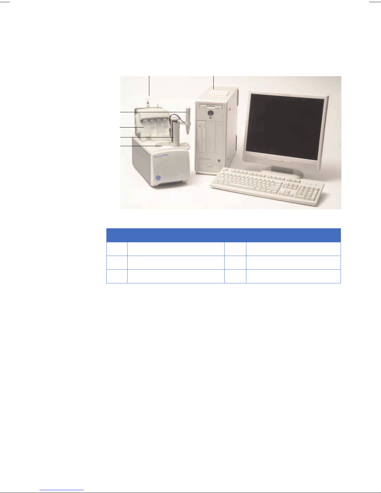
Figure 1-2. MicroCal iTC
complete system.
200
1
Part Description Part Description
1 Controller 4 Washing module
2 MicroCal iTC
200
5Tower
3 Pipette 6 Cell Unit
Temperature differences between the reference cell and the sample cell are measured,
calibrated to power units and displayed to the user as well as saved to disk. The data
channel is referred to as the DP signal, or the differential power between the reference
cell and the sample cell. This signal is sometimes thought of as the "feedback" power
used to maintain temperature equilibrium. Calibration of this signal is obtained
electrically by administering a known quantity of power through a resistive heater
element located on the cell.
In a typical experiment, the syringe containing a ligand is titrated (injected) into the cell
containing a solution of macromolecule. An injection which results in the evolution of
heat (exothermic) within the sample cell causes a negative change in the DP power,
since the heat evolved chemically provides heat that the DP feedback is no longer
required to provide.
The opposite is true for endothermic reactions. Since the DP has units of power, the time
integral of the peak yields a measurement of thermal energy, dH. This heat is released
or absorbed in direct proportion to the amount of binding that occurs. When the
macromolecule in the cell becomes saturated with added ligand, the heat signal
diminishes until only the background heat of dilution is observed.
MicroCal iTC
Operating Instructions 28-9639-77 AA 11
200
Page 12

1 Introduction
1.3 Instrument
With the MicroCal iTC
system the entire experiment takes place under computer
200
control. The user inputs the experimental parameters (temperature, number of
injections, injection volumes) and the computer carries out the experiment.
<DoNotTranslate_GE_Color>Origin™ software is then used to analyze the ITC data
using fitting models to calculate reaction stoichiometry (n), binding constant (K
),
A
enthalpy (ΔH) and entropy (ΔS).
12 MicroCal iTC
Operating Instructions 28-9639-77 AA
200
Page 13
1.4 Control software
In order for the system to initialize properly, all components must be powered up in the
correct order. First, boot up the computer and log in to Windows. Once Windows has
started, power the MicroCal iTC
several seconds, open the MicroCal iTC
copy of <DoNotTranslate_GE_Color>Origin will open automatically, as well as the
MicroCal iTC
control software.
200
Introduction 1
Control software 1.4
by operating the switch at the rear of the unit. After
200
software. If the option is selected, a real-time
200
MicroCal iTC
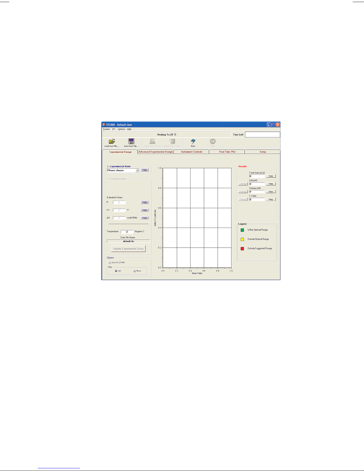
Figure 1-3. Instrument control software.
When the instrument first boots up, the line just below the menus reads "System
Initialization - Please Wait", which is the current status of the instrument. After a few
seconds, the system will begin heating or cooling to the preset temperature. If the
instrument is not attached or not turned on, the program will open into Demo Mode, in
which the user can see and manipulate the program, but it will not attempt to control
the MicroCal iTC
. To the right of the status bar, the Time Left box, during a run, will
200
show the time left until the end of the run.
When the software is first started, the Experimental Design tab is selected; this
contains the simple run controls. Experimental Mode can be Highest Quality, Minimum
Protein, or High Speed. The expected n, K
, and ΔH and the desired run temperature will
D
allow the software to calculate the recommended concentrations for the cell and
syringe, and set the run parameters. The Advanced Experimental Design tab contains
more direct controls for the more advanced user. This tab should be very familiar to
users of the VP line of instruments. The Instrument Controls tab allows the user to
name the output files, choose post-run analysis options, and start and stop the run. The
Real Time Plot tab shows the data currently being generated. The Setup tab contains
various options and preferences.
Operating Instructions 28-9639-77 AA 13
200
Page 14
1 Introduction
1.4 Control software
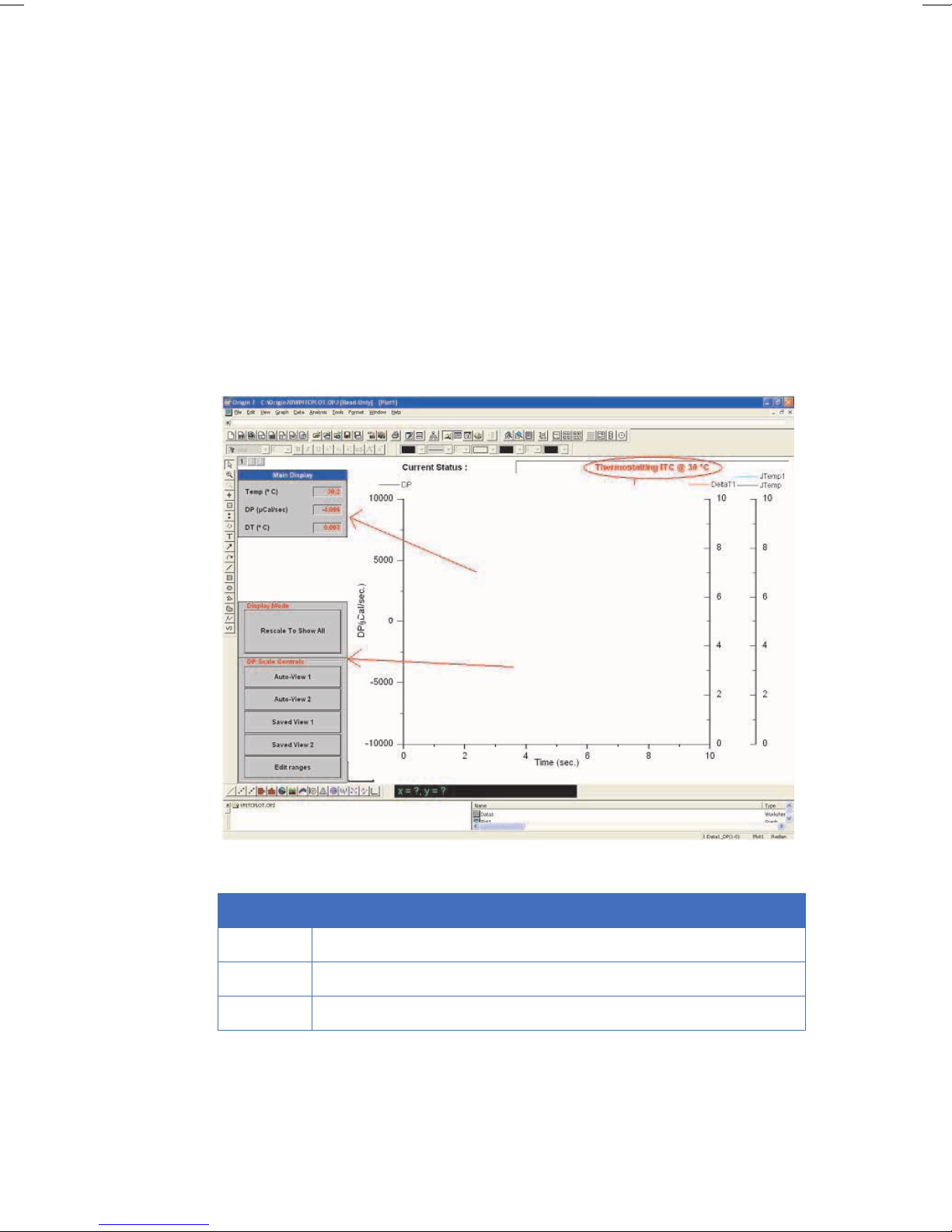
Origin software
Origin Real-Time Display
This section describes the functionality of the optional copy of
<DoNotTranslate_GE_Color>Origin for real-time display. When the software is opened,
it will open the <DoNotTranslate_GE_Color>Origin™ project window VPITCPLOT.OPJ for
real time data display. This project of <DoNotTranslate_GE_Color>Origin is dedicated to
data display only, and should not be used for data analysis. Users should open a
separate copy of <DoNotTranslate_GE_Color>Origin for MicroCal iTC
analysis. Pictured below is the main <DoNotTranslate_GE_Color>Origin window for
MicroCal iTC
data display.
200
to perform data
200
1
2
3
Figure 1-4. <DoNotTranslate_GE_Color>Origin Real-Time display.
No. Description
1iTC cell status
2iTC numeric display
3 Buttons for iTC data display
The ITC cell status, the MicroCal iTC
data tools (as indicated above) have been added for user convenience in viewing
iTC
200
data generated by the MicroCal iTC
14 MicroCal iTC
numeric display and the buttons for MicroCal
200
. For a more thorough description of these real-
200
Operating Instructions 28-9639-77 AA
200
Page 15

Introduction 1
Control software 1.4
time tools in <DoNotTranslate_GE_Color>Origin, refer to the MicroCal iTC
Experimental and Data Analysis Tutorial Guide.
200
MicroCal iTC
Operating Instructions 28-9639-77 AA 15
200
Page 16

1 Introduction
1.4 Control software
16 MicroCal iTC
Operating Instructions 28-9639-77 AA
200
Page 17

2 Safety instructions
The points below are intended to enhance your safety awareness and to draw your
attention to risks which only you, the operator, can prevent . While GE Healthcare works
to ensure that the instrument is designed and tested to be as safe as possible, proper
handling is also critical. The operators should be responsible people trained in basic
laboratory protocol, and they should be familiar with the possible hazards before
operating this instrument. All instrument modifications should be performed only by
personnel trained by GE Healthcare. Equipment damage, personal injury or even death
may result if this equipment is operated, altered or maintained by untrained personnel
or in an irresponsible or improper manner.
2.1 Safety precautions
Safety instructions 2
Safety precautions 2.1
Introduction
Before installing, operating of maintaining the system, you must be aware of the
hazards described in the user documentation. Follow the instructions provided to avoid
personal injury or damage to the equipment.
The safety precautions in this section are grouped into the following categories:
• General precautions
• Flammable liquids
• Personal protection
• Installing and moving the instrument
•System operation
•Maintenance
MicroCal iTC
Operating Instructions 28-9639-77 AA 15
200
Page 18
2 Safety instructions
2.1 Safety precautions
General precautions
WARNING!
Provide proper electrical power to the instrument. This should be 100 –
240 Volt, 50/60 Hertz alternating current, with a Ground Fault Circuit
Interrupter (GFCI). Some power strips, such as the one provided by GE
Healthcare with your instrument, contain a GFCI. All power plugs and
cords should be 3-prong, grounded cables or outlets.
WARNING!
In case of fire, unplug instrument.
WARNING!
Do not operate the MicroCal iTC
the MicroCal iTC
and/or Auto-MicroCal iTC
200
in any other way than described in
200
manuals.
200
WARNING!
Make sure the rear power connector is always accessible.
WARNING!
Use caution when using solutions near the instrument. If any liquid is
spilled on or around the instrument, unplug the instrument immediately
and wipe it up. If there is any possibility that liquid may have leaked into
the instrument case, contact GE Healthcare immediately. Do not plug
the instrument into any electrical outlet until the problem is resolved.
WARNING!
This instrument is not designed to the Medical Devices Directive 93/42/
EEC and should not be used for medical purposes and/or in the
diagnosis of patients.
NOTICE
The MicroCal iTC
cells are constructed out of Hastelloy. Strong acids
200
should be avoided.
16 MicroCal iTC
Operating Instructions 28-9639-77 AA
200
Page 19
Using flammable liquids
WARNING!
A fume hood or similar ventilation system shall be installed when
flammable or noxious substances are used.
WARNING!
Fire Hazard. Before starting the system make sure that there is no
leakage.
Personal protection
WARNING!
Always use protective glasses and other personal protective equipment
appropriate with the current application, to ensure personal safety
during operation.
Safety instructions 2
Safety precautions 2.1
WARNING!
The operator should always follow proper laboratory procedures in
handling and disposing of volatile or hazardous solutions.
WARNING!
This instrument is used for a wide variety of experiments that can utilize
potentially hazardous materials. Use of these could cause exposure to
biological, chemical and radiation hazards depending on the user’s
experiments. Users should educate themselves about the samples they
are using to avoid these hazards.
MicroCal iTC
Operating Instructions 28-9639-77 AA 17
200
Page 20

2 Safety instructions
2.1 Safety precautions
Installing and moving the
instrument
WARNING!
Power cord. Only use power cords delivered or approved by GE
Healthcare.
WARNING!
Do not block the ventilation inlets or outlets on the system.
WARNING!
The Washing Module may only be powered by the power supply
provided with the Unit.
WARNING!
Installing the controller. The controller should be installed and used
according to the instructions provided by the documentation included
in the shipment.
WARNING!
Replace fuses ONLY with 4.00 Amp 250 Volt Time Delay Fuses. Several
spare fuses are provided with the original shipment.
WARNING!
Access to power switch and power cord. Do not block the rear and side
panel of the instrument. The Power switch must always be easy to
access. The power cord must always be easy to disconnect.
NOTICE
Disconnect power. To prevent equipment damage, always disconnect
power from the MicroCal iTC
and washing module system before an
200
instrument module is removed or installed or a cable is connected or
disconnected.
System operation
WARNING!
All solutions in the cells must be cooled down below 40ºC before
removal. Any higher temperature may cause the syringe to break, and
will increase the dangers of most hazardous solutions.
18 MicroCal iTC
Operating Instructions 28-9639-77 AA
200
Page 21

Safety instructions 2
Safety precautions 2.1
WARNING!
Do not place containers of liquid on top of the instrument, except those
designed for the washing module. Spilled liquid is a fire and electrical
hazard.
CAUTION
Waste tubes and containers shall be secured and sealed to prevent
accidental spillage.
NOTICE
Never allow liquid in the cells to freeze. The expansion of the liquid can
distort the cells and rupture the most critical sensor, causing irreparable
damage.
NOTICE
Intermittent operation of the Washing Module is required so that the
Washing Module valves are on for a maximum of 20 minutes, then off for
30 minutes. Software limits the valve on period to 10 minutes before an
experiment, so this does not affect normal operation of the instrument.
Maintenance
NOTICE
The MicroCal iTC
instrument should always be moved in its normal
200
operating orientation. Other orientations will subject delicate sensors
inside the instrument to stress.
WARNING!
Replace fuses ONLY with same type fuses. Several spare fuses are
provided with the original shipment and the power receptacle is labeled
with the correct type.
WARNING!
Repairs, alterations or modifications must only be carried out by a GE
Healthcare specialist , or with explicit directions from a GE Healthcare
technician. Removal or modification of any cover or component could
result in an unsafe or easily damaged instrument. The GE Healthcare
service department will be happy to answer any questions and provide
parts and service when necessary.
WARNING!
Only spare parts that are approved or supplied by GE Healthcare may
be used for maintaining or servicing the system.
MicroCal iTC
Operating Instructions 28-9639-77 AA 19
200
Page 22

2 Safety instructions
2.1 Safety precautions
WARNING!
Disconnect power. Always disconnect power from the instrument before
replacing any component on the instrument, unless stated otherwise in
the user documentation.
WARNING!
Hazardous chemicals during run. When using hazardous chemicals,
flush the entire system tubing with distilled water, before service and
maintenance.
WARNING!
Hazardous chemicals during maintenance. When using hazardous
chemicals for cleaning, wash the system with a neutral solution in the
last phase or step.
WARNING!
Decontaminate the equipment before decommissioning to ensure the
removal of all hazardous residues.
equipment.
WARNING!
CONTRAD® 70 (Decon 90) is corrosive and therefore dangerous to
health. When using hazardous chemicals, avoid spillage and wear
protective glasses, gloves, and other suitable personal protective
20 MicroCal iTC
Operating Instructions 28-9639-77 AA
200
Page 23

2.2 Labels
Labels on the instrument
The illustration below shows an example of the identification labels attached to the rear
of the MicroCal iTC
instrument.
200
Safety instructions 2
Labels 2.2
Figure 2-1. Back panel of instrument.
Labels on the USB hub
The illustration below shows an example of the label on the back of the USB hub.
Figure 2-2. USB hub label.
MicroCal iTC
Operating Instructions 28-9639-77 AA 21
200
Page 24

2 Safety instructions
2.2 Labels
Labels on the Washing Module
The illustration below shows an example of the identification labels attached to the rear
of the Washing Module.
Figure 2-3. Labels on Washing Module.
22 MicroCal iTC
Operating Instructions 28-9639-77 AA
200
Page 25

Symbols used in safety labels
Labels concerning hazardous
substances
Safety instructions 2
Labels 2.2
The system complies with the requirements for
electromagnetic compliance (EMC) in Australia and New
Zeeland.
Warning! Read the user manual before using the system. Do
not open any covers or replace parts unless specifically
stated in the user manual.
The system complies with applicable European directives.
Emergency procedures
In an emergency situation, do as follows to stop the run:
Step Action
1 Disconnect the equipment from the power outlet .
Power failure
MicroCal iTC
• The run is interrupted immediately, in an undefined state.
This symbol indicates that the waste of electrical and
electronic equipment must not be disposed as unsorted
municipal waste and must be collected separately. Please
contact and authorized of the manufacturer for information
concerning the decommissioning of equipment.
This symbol indicates that the product contains hazardous
materials in excess of the limits established by the Chinese
standard SJ/T11363-2006. Requirements for Concentration
Limits for certain Hazardous Substances in Electronics.
200
• The data collected up to the time of the power failure is saved.
MicroCal iTC
Operating Instructions 28-9639-77 AA 23
200
Page 26

2 Safety instructions
2.2 Labels
Controller
• The controller shuts down, in an undefined state.
•The MicroCal iTC
run is interrupted immediately, in an undefined state.
200
Washing module
• The washing module shuts down immediately, in an undefined state.
24 MicroCal iTC
Operating Instructions 28-9639-77 AA
200
Page 27

2.3 Recycling procedures
The equipment shall be decontaminated before decommissioning and all local
regulations shall be followed with regard to scrapping of the equipment.
Disposal, general instructions
When taking the MicroCal iTC
separated and recycled according to national and local environmental regulations.
Recycling of hazardous
substances
The MicroCal iTC
available from your GE Healthcare representative.
Disposal of electrical
components
Waste of electrical and electronic equipment must not be disposed as unsorted
municipal waste and must be collected separately. Please contact an authorized
representative of GE Healthcare for information concerning the decommissioning of
equipment.
instrument contains hazardous substances. Detailed information is
200
Safety instructions 2
Recycling procedures 2.3
system out of service, the different materials must be
200
MicroCal iTC
Operating Instructions 28-9639-77 AA 25
200
Page 28

2 Safety instructions
2.3 Recycling procedures
26 MicroCal iTC
Operating Instructions 28-9639-77 AA
200
Page 29

3 Installation
NOTICE
It is recommended that the installation of the MicroCal iTC
be performed by GE Healthcare personnel.
Installation 3
Site requirements 3.1
instrument
200
This section provides information about the installation of MicroCal iTC
Figure 3-1. MicroCal iTC
Any equipment connected to the MicroCal iTC
with washing module and control computer..
200
must fulfill applicable standards and
200
local regulations.
200
.
3.1 Site requirements
The MicroCal iTC
70 cm wide). This location should be away from strong drafts, room temperature
fluctuations, intense sunlight, vibrations and strong electrical or magnetic fields (as
may be produced by an NMR, microwave oven, large motors or refrigeration units). In
addition the mains power source (100 to 240 VAC) should be properly grounded and free
from voltage fluctuations, harmonic distortions, power dips and spikes. The AC power
line should be dedicated to the MicroCal iTC
with additional equipment.
MicroCal iTC
Operating Instructions 28-9639-77 AA 27
200
with Controller requires about 1 meter of normal bench space (ca.
200
system and should not share that power
200
Page 30

3 Installation
3.1 Site requirements
Although, the power filtering in the MicroCal iTC
instrument is adequate for most
200
laboratory environments, some disturbances may affect the performance of the
instrument and it may be necessary to have the AC Mains power source evaluated (see
table below) or install a power conditioner. Since power source problems can be
manifested in many different ways, it is not possible to recommend a power conditioner
for all situations. It is recommended that you test a power conditioner, at your location,
before you purchase it. If you believe you are experiencing power source related
problems, please contact a GE Healthcare field engineer.
Table 3-1. Power supply requirements.
AC Mains Requirements
Specification Requirement
Voltage Regulation 100 to 240 VAC, stable to ± 3%
Frequency Stability 0.5% Maximum Deviation
Power Line Noise < 3% Common Mode or Differential Mode at any
Frequency
Harmonic Content < 5% Total Harmonic Distortion to 1500 Hz, < 3% For
any Single Frequency
Ground Noise < 1 VAC Peak-To-Peak, < 2 VAC Ground to Neutral
Peak-To-Peak at any Frequency
Ground Quality < 25 Ohm
It is emphasized that room temperature fluctuations (i.e. maximum 2.5 ºC) due to the
cycling on/off of heating and cooling systems, strong air currents, sunlight directly on
the instrument and through space electromagnetic waves may cause subtle
performance problems.
Table 3-2. Environmental operating requirements.
Environmental (Operating) requirements
Temperature 10 to 28ºC, constant to 2.5ºC
Humidity 0 to 70% Relative Humidity, non-condensing
Atmospheric Pressure 700 hPa to 1060 hPa
28 MicroCal iTC
Operating Instructions 28-9639-77 AA
200
Page 31

3.2 Transport
Before moving the system:
• Disconnect all cables and tubing connected to peripheral components and liquid
containers.
• Remove all items from the top of the system.
• Grasp the system under the two sides.
3.3 Unpacking
The MicroCal iTC
with great care.
Installation 3
NOTICE
Lift the MicroCal iTC
front panel cover as a lifting handle.
is delivered in protective packing material and shall be unpacked
200
instrument in the upright position. Do not use the
200
Transport 3.2
3.4 Set up
Check the equipment for damage before starting assembly and installation.
Document any damage and contact your local GE Healthcare representative.
Arrange the components on the desktop similar to the picture of the system (see Figure
3-1). The computer may be on either side depending on convenience. Do not place the
wash station into position yet. Follow the instructions below for assembly.
NOTICE
Before connecting the hardware, make sure the controller PC is off.
MicroCal iTC
Operating Instructions 28-9639-77 AA 29
200
Page 32

3 Installation
3.4 Set up
1 Remove the top and front panel.
2 Remove the three screws and washers on the top of the instrument used to mount
the injection tower.
1
5
2
6
7
3
8
9
4
Figure 3-2. MicroCal iTC
with washing module.
200
Part Description
1 Cell cleaning adaptor
2 Washing module
3 Solution tubes (Waste, Water, Methanol, Buffer)
4Cell port
5 Fill port adaptor
6Pipette
7Pipette tower
8 Syringe washing and drying station
9 Tube holder
30 MicroCal iTC
Operating Instructions 28-9639-77 AA
200
Page 33

Installation 3
Set up 3.4
3 Attach the tower with the washers and screws. Do not seat the screws but leave
them just slightly loose enough to slide the injector around for alignment in step 5.
4 Carefully insert the pipette into the lock ring. Ensure that the pipette is fully seated
and the black cable is parallel with the arm before tightening the screw (below).
5 Very carefully insert the pipette into the cell. You may need to move the injector a
small amount to achieve this, and avoid bending the syringe.
6 Align the pipette in the center of the port such that the pipette slides in/out of the
cell easily and the spaces on both sides of the pipette are even. This alignment is
critical to achieve acceptable noise levels. Hold the injection tower down firmly
with one hand while tightening the screws with the other.
7 Plug the pipette connector to the back of the injector tower riser and tighten the
lock screws with a 0.05 inch hex driver (1.3mm).
8 Lift the black locking clip on the front of the instrument on the interconnection
board behind the faceplate. Insert the ribbon cable from the injection mechanism
until it seats.
9 Alternately push the locking clip down to hold the cable in place.
10 Snap the two cover plates back into place.
Washing module installation
USB connector types
The MicroCal iTC
with different connector types. You have been supplied with two cables that have Type
A and Type B connector ends.
An additional cable has been supplied that has Type A and Type B (mini) connector ends.
Table 3-3. Cable connectors.
Connector Description
cell and Washing Module connect to the host PC through USB ports
200
Type A
Type B (mini)
MicroCal iTC
Operating Instructions 28-9639-77 AA 31
200
Type B
Page 34

3 Installation
3.4 Set up
1 Identify the only cable with the USB type B (mini) cable end. Connect the type B
(mini) cable end to the USB hub (see Fig 3-4). Connect the USB type A end of that
cable to the labeled Controller PC USB port.
A
Figure 3-3. Controller connector to PC (A).
2 Connect the USB type A ends of two USB cables to the hub as shown in Figure 3-5.
Figure 3-4. USB connectors.
3 Connect the USB type B ends to the USB 1 and USB 2 connectors on the rear of the
MicroCal iTC
4 Place the Washing Module on top of the MicroCal iTC
instrument (Fig 3-6).
200
200
cell.
5 Connect the USB type A end from the Washing Module to the hub (Fig 3-6).
32 MicroCal iTC
Operating Instructions 28-9639-77 AA
200
Page 35

Installation 3
Set up 3.4
6 Connect the green grounding strap wire between the Washing Module and the
MicroCal iTC
1
200
cell.
Figure 3-5. Washing Module and MicroCal iTC
Note: 1 in Figure 3-5 is the power cord grommet.
MicroCal iTC
Operating Instructions 28-9639-77 AA 33
200
200
cell.
Page 36

3 Installation
3.4 Set up
Electrical connections
MicroCal iTC
200
cell
Connect the power cord to the IEC 320 inlet power receptacle (see Figure 3-6 below) on
the back of the cell. Connect the power plug only to a main power supply receptacle
with a 3-wire protective Earth ground and a Ground Fault Circuit Interrupter (GFCI).
WARNING
To enhance safety always plug the instrument into a Ground Fault
Circuit Interrupter (GFCI) device.
1
2
3
4
Figure 3-6. MicroCal iTC
Part Description Part Description
1Fan 4Power fuses
2 & 6 USB connectors 5 IEC 320 inlet power receptacle
3 Mains power switch 7 µP activity indicator
Washing module
Connect the power cord from the power supply to the power receptacle (see Figure 3-7)
on the rear of the Washing module (see Figure 3-6, Power). Connect the power supply
view of back plate.
200
5
6
7
34 MicroCal iTC
Operating Instructions 28-9639-77 AA
200
Page 37

Installation 3
Set up 3.4
only to a main power supply receptacle with a 3-wire protective Earth ground and a
Ground Fault Circuit Interrupter (GFCI).
WARNING
To enhance safety always plug the instrument into a Ground Fault
Circuit Interrupter (GFCI) device.
Figure 3-7. Washing module power supply unit
MicroCal iTC
Operating Instructions 28-9639-77 AA 35
200
Page 38

3 Installation
3.4 Set up
Fluid connections
Figure 3-8. Washing Module pipette wash station connections.
Attach Washing Module Tubing
• C1 to syringe fill port (Figure 3-8),
• C2 to needle wash port (Figure 3-8),
• C3 to top of cleaning device (Figure 3-9),
• C4 to side of cleaning device (Figure 3-9),
•C5 to waste (Figure 3-9).
Figure 3-9. Cell tool connections.
36 MicroCal iTC
Operating Instructions 28-9639-77 AA
200
Page 39

Installation 3
Validation 3.5
Insert the vacuum vial and three solvent vials
1 To install the vacuum vial (1 in Figure 3-10) slide the vial up and back, and screw it
into its socket.
2 To install a vial, insert the fill tubing and filter, if applicable, into the vial and slide it
up and back into its slot.
1
2
3
4
Figure 3-10. Solution vials.
Table 3-4. Solution vials
.
Part Description Part Description
1 Vacuum vial (opaque
3 Methanol vial
color)
2 Distilled water vial 4 Buffer vial
Note: If buffer is not desired for some reason, this vial may also be filled with water.
CAUTION
The methanol should be removed and capped when the instrument is
not in use, as methanol is very volatile.
3.5 Validation
After installation it is recommended that a titration of a known system be performed to
test that the instrument has been installed correctly.
MicroCal iTC
Operating Instructions 28-9639-77 AA 37
200
Page 40

3 Installation
3.6 Configuring a MicroCal iTC
controller for networking
200
3.6 Configuring a MicroCal iTC
On a MicroCal iTC
networking and MicroCal iTC
watchdog program must be removed, and once the computer has been configured for
the local domain, two folders must be given special permissions.
Uninstallation:
1Click on the START button on the lower left side of the screen, and then on Control
Panel.
2In the Control Panel window, click on Add or Remove Programs.
3Find InitDTSetup in the program list. Click the Remove button by it. In the next
window, click Yes to confirm the removal.
Special Permissions:
The MicroCal iTC
folders. In order to allow a non-administrator to use this software, read/write privileges
must be set for all users for the MicroCal iTC
folders. The folder properties must allow Read & Execute, List Folder Contents, Read,
and Write, as shown below.
controller, there are several actions that must be performed for the
200
200
so ftwar e and Origi n both need t o be abl e to wri te data into th eir ow n
200
controller for networking
200
control software to work properly. First , the InitDT
and Origin 70 folders, including all sub-
200
Figure 3-11. Configuration dialogs.
38 MicroCal iTC
Operating Instructions 28-9639-77 AA
200
Page 41

4Operation
4.1 Procedure before a run
Note: See Section 1.4 for control software information.
On / Off Instructions
Operation 4
Procedure before a run 4.1
Turning the MicroCal iTC
Once the MicroCal iTC
the cell unit is a power on/off switch, which functions as the master power switch and
must be in the “on” position. It can be turned to “off” when the MicroCal iTC
not be used for long periods of time i.e., weekends, holidays, etc.
NOTICE
The user interface program, iTC200, has to be running for the cell to
function properly even though the power switch is in the “on” position.
Leaving the power on
During frequent “on” periods, the master power may be left as long as the user interface
program, MicroCal iTC
system is does not incur any damage and keeps the MicroCal iTC
Periods of inactivity
GE Healthcare recommends that the MicroCal iTC
master power be turned off, when the system will not be used for extended periods of
time.
cell on
200
cell has been cabled to the PC, it is ready to use. At the rear of
200
cell will
200
, is running. The software automatically ensures that the
200
cell ready.
200
application be closed and the
200
4.2 Basics of performing a run
In order to perform a basic ITC titration experiment, the user must load the sample cell
and the syringe, enter the desired parameters into the control software, and click Start.
The reference cell should be filled with water or buffer, and may be left for several days.
4.3 Loading the syringe
To load the titration syringe, place a micro centrifuge tube containing ~100µL of your
sample in the tube holder. Be sure to push the tube to the bottom of the holder with the
MicroCal iTC
Operating Instructions 28-9639-77 AA 39
200
Page 42

4 Operation
4.4 Loading the cell
lid fitting into the slot provided (see image below). Be careful not to leave any part of the
tube in the path of the syringe needle to prevent damage.
Figure 4-1. Micro centrifuge tube in the tube holder.
Figure 4-2. Fill port adapter threaded into fill port.
Connect the threaded end of the tubing from the Washing Module to the pipette fill port
if necessary (it should still be in place after cleaning and drying of the syringe).
NOTICE
Avoid overtightening the tubing in the pipette fill port. Excessive force will
crack the syringe.
In the Instrument Controls tab, click Syringe Fill. The software will prompt the user to
move the pipette as necessary, and the Washing Module will fill the syringe. See
sections 4.4 to 4.7 for more information.
4.4 Loading the cell
To load the cell do the following:
1 To load the sample cell, gently insert the glass Hamilton syringe into the (left)
sample cell until it touches the bottom.
2 Pull up on the plunger until bubbles are being pulled from the cell, and there is no
more liquid.
3 Remove and empty the syringe. Clean the syringe if necessary.
40 MicroCal iTC
Operating Instructions 28-9639-77 AA
200
Page 43

Operation 4
Loading the cell 4.4
4 Pull approximately 300 µl of sample into the syringe, and tap the syringe glass so
that all air is at the top volume of the syringe. Do not allow air to be put into the
cells.
5 After removing the bubbles, insert the syringe into the cell and gently touch the
bottom of the cell with the tip of the syringe needle.
6 Raise the needle tip about 1 mm off the bottom of the cell, and hold it there until
finished filling. Do not raise the syringe during the filling process.
7 Slowly inject solution into the cell until it spills out the top of the cell stem. Finish the
filling with several small abrupt spurts of solution to dislodge any bubbles in the
cells.
8 Finally, lift the tip of the syringe to the cell port (just below the visible portion of the
cell port) and find the ledge (See Figure 4-3) that is formed where the cell stem
meets the cell port. Place the syringe on the ledge at the top of the metal cell stem
and remove the excess solution. If the reference cell needs ref illing, follow the same
procedure as for the sample cell.
1
Figure 4-3. Schematic representation of the cell (left) and the top of the cell stem (right) where air
bubbles can form if not loaded properly.
2
Part Description
1 Place where bubbles are trapped.
2 Ledge formed where cell stem meets plastic overflow reservoir.
Load the run parameters by clicking the Load Run File button at the top left of the
Advanced Experimental Design tab in the MicroCal iTC
software and select the
200
WATER. inj file. This will populate all the required fields for performing a run. Then click
the Start button on the bar of buttons across the top of the control software.
MicroCal iTC
Operating Instructions 28-9639-77 AA 41
200
Page 44

4 Operation
4.5 Experimental design
Be sure to insert the syringe in to the sample cell before starting the experiment. The
instrument will seek experimental temperature, equilibrate to that temperature, start
the titration syringe stirring, wait until the DP signal is steady, and then start performing
injections. The raw data will appear in the Real Time Plot tab.
Once a run has finished, the syringe and sample cell should be cleaned as soon as
possible.
Procedures after a run
The MicroCal iTC
will keep the system electronics at the normal operating temperature. It is
recommended that the power of the MicroCal iTC
periods of down time, such as holidays and vacations.
After use, clean the sample cell following procedure in Section 4.7 and fill the sample cell
with distilled water. Wash and dry the syringe using procedure in section Section 4.7.
was designed to have its power on for extended periods of time. This
200
cell be turned off during extended
200
4.5 Experimental design
Figure 4-4. Experimental design dialogue box.
42 MicroCal iTC
Operating Instructions 28-9639-77 AA
200
Page 45

Operation 4
Advanced experimental design 4.6
When the software is first started, by default, the Experimental Design tab is selected;
this contains the simple run controls. Experimental Mode can be Highest Quality,
Minimum Protein, or High Speed. Highest Quality uses 20 injections.
These parameters should produce data that is clear and easier to fit. Minimum Protein
uses fewer injections, only 10. The result of these parameters will be the use of the least
amount of sample necessary for a successful titration.
The High Speed mode will do one single longer injection (Single Injection Mode, SIM).
The expected n, Kd, and H and the desired run temperature will allow the software to
calculate the recommended concentrations for the cell and syringe, and set the run
parameters based on mode chosen.
If the user is unsure of the Kd for their system, clicking the Help button causes the
software to prompt for the type of compound in cell and syringe. It will then make a
guess as to the Kd. The user will still be required to choose values for H and n.
Click the Update Experimental Curve button to calculate the results. The simulation
window will update with a rough graph, and the Results column at the right of the
screen will have values for the cell and syringe concentrations. The calculated C value
is listed below; its background is color-coded.
The C-value predicts the shape or sigmoidicity of the curve. Optimal values for C are
between 5 and 500 (green); values between 1 and 5, and 500 and 1000 should work but
may not give the best result (yellow). C values less than 1 or greater than 1000 will
probably not yield usable data (red).
The user may adjust the two experimental concentrations by using the change buttons
beside each concentration box.
Any warnings, such as heats too high for the instrument to measure, will appear in the
status bar near the top of the screen. It is highly recommended that the users look
carefully at the projected curve and make sure that the shape and rough values are
reasonable before proceeding.
A pair of options at the bottom of this tab allows users to work in K
whether to view the simulation plot using raw heat per injection (ΔH) or the heat
normalized to the molar ratio (NΔH).
4.6 Advanced experimental design
This may be used in addition to the Experimental Design tab to modify the suggested
run parameters. It can also be used to save or upload run (*.in) files.
See MicroCal iTC
Experimental and Data Analysis tutorial Guide.
200
or KA, and to choose
D
MicroCal iTC
Operating Instructions 28-9639-77 AA 43
200
Page 46

4 Operation
4.7 Instrument controls
4.7 Instrument controls
Figure 4-5. Instrument control screenshow.
The Instrument Controls tab contains the controls for direct operation of the
instrument. At the top of the window, the user can Start the run, using whatever
parameters are currently present in the Experimental Design or Advanced
Experimental Design tabs.
Before clicking this button, it is wise to check that all parameters are correct and that a
valid, unique data file name has been entered. The software will double-check with the
user before allowing any files to be overwritten. The Stop button, which is available only
during a run, will abort the run immediately.
The Thermostat Control section allows for setting of the thermostat temperature,
which will be maintained during the MicroCal iTC
thermostatting the MicroCal iTC
and samples at the run temperature will result in
200
thermostatic (idle) state. Pre-
200
shorter equilibration times. Also, high temperature thermostatting during cell cleaning
can improve the effects of the cleaning. Use the arrow buttons to raise or lower the
temperature or click in the text box and type in a new number. Click Set Jacket Temp to
set the temperature.
44 MicroCal iTC
Operating Instructions 28-9639-77 AA
200
Page 47

Operation 4
Instrument controls 4.7
The Pulse Control section allows for manually administering a DP calibration pulse.
While this is not the most thorough method of checking the y-axis calibration, it is the
quickest method. Pulses may be applied any time the DP signal is equilibrated and the
resulting deflection used as a crude calibration assessment. If Origin for real-time
plotting is enabled, Origin will calculate the error. If this is greater than 1%, please see
Section 5.8 for a more thorough check of the DP calibration.
The Pipette Control panel at the center of this tab provides the controls for loading and
cleaning the syringe. The Open Port button moves the plunger tip to above the fill port
in the side of the syringe. Close Port moves the plunger tip down so that it blocks the fill
port. Purge/Refill pushes the pipette tip all the way down and back up again, dislodging
bubbles on the sides of the syringe. The Pipette Maintenance section provides the
software controls used for changing the pipette tip. Please see Section 5.5 for details on
performing this maintenance.
Insert the cell cleaning apparatus into the sample cell (see pictures below). Be sure to
push down until the device is firmly seated. Attach the syringe connector to the syringe.
Click the Cell and Syringe Wash button in the Instrument Controls tab of the iTC200
software. The software will prompt the user to be sure the cleaning tubing is inserted.
The program will first execute the Cell Buffer Rinse (Short) procedure.
A prompt will appear after the cell wash portion of the sequence is complete. The user
may then load the cell. Click OK to continue and clean the syringe. The program then
executes the Syringe Wash (Short) procedure. The syringe cleaning takes about nine
minutes. Once that has completed, the syringe may be loaded with sample.
Leave the tubing connected to the syringe. Leave the syringe in the wash position or the
rest position. Click Syringe Load.
The plunger will move to the bottom of the syringe to prepare for loading. This must be
performed with the syringe NOT in the titrant to prevent turbulence and gassing of the
sample. The software will prompt the user to move the pipette to the titrant .
Click OK to continue. The pipette tip will move, filling the syringe. After the tip reaches
the open port position, the pump will remove the air bubble, reducing titrant usage. The
port will move to the close position and the vacuum will remove any excess titrant . Once
this has completed, the software will prompt the user to disconnect the syringe tubing,
make sure the cells are filled, and move the pipette into the sample cell.
The cell cleaning device must be inserted into the sample cell until it seats firmly.
Connect the syringe tubing to the vacuum block port at the rear of the Washing Module
to prevent leakage. Click Cell Buffer Rinse (Short). The Washing Module will perform a
short cleaning routine, rinsing the cell with buffer.
The program will rinse the cells with buffer and then with water. It will then empty the
cell, although not all the liquid will be removed. The entire sequence takes a little over a
minute. The user may then remove the excess water and load the cell with sample,
using the Hamilton loading syringe.
The cell cleaning apparatus must be inserted into the sample cell until it seats firmly.
Connect the syringe tubing to the vacuum block port to prevent leakage. Click Cell
Water Rinse (Long). The Washing Module will perform a more thorough cleaning
routine, which takes about 80 seconds. Like the Cell Buffer Rinse (Short), the program
MicroCal iTC
Operating Instructions 28-9639-77 AA 45
200
Page 48

4 Operation
4.8 Real time plot
will rinse the cell, this time with water, using greater quantities. This is especially useful
after a detergent soak, to be sure of removing all of the detergent.
Click the Detergent Soak and Rinse (Long) button and follow the prompts to load ~5%
Contrad70.
The cells will heat to 50°C for half an hour to soak. Once they have cooled, the software
will prompt the user to remove the Contrad70 and insert the cleaning device for rinsing,
and then to connect the pipette connector to its holder. Be sure that the cells have
cooled before removing the Contrad70, as hot liquid may shatter the loading syringe.
This method is used when more vigorous cleaning is required, after a precipitating
sample or if trouble is suspected. It is also a good idea to do this every few weeks, or
every few days for an instrument under heavy use, to prevent problems.
Connect the syringe tubing to the syringe fill port. Click Syringe Wash (Short). The
software will prompt the user to make sure that the tubing is connected.
Click OK. The Washing Module will perform a short washing routine (approximately 8
minutes). It will rinse the syringe first with water and then with methanol. It will then pull
vacuum through the syringe for several minutes to dry it.
Connect the syringe tubing to the syringe fill port. Click Syringe Wash (Long). The
software will prompt the user to make sure that the tubing is connected.
Click OK. The Washing Module will perform a more thorough washing routine
(approximately 8½ minutes). It will rinse the syringe first with water and then with
methanol. It will then pull vacuum through the syringe for several minutes to dry it.
The Dry Syringe function is used when the syringe has been cleaned manually and left
with methanol in it. Attach the syringe connector to the syringe and place the pipette in
the wash position. Click the Dry Syringe button.
The washing module will pull vacuum through the syringe for several minutes to dry it.
4.8 Real time plot
This tab displays the current DP data.
See MicroCal iTC
4.9 Set up
This tab allows for the customizing of data file paths for data storage and setup files. It
is also where the Extended Data Mode button can be found. It is useful to have this box
checked when running test experiments. The additional data it provides will be helpful
for troubleshooting. See MicroCal iTC
Experimental and Data Analysis tutorial Guide.
200
Experimental and Data Analysis tutorial Guide.
200
46 MicroCal iTC
Operating Instructions 28-9639-77 AA
200
Page 49

4.10 Procedures after a run
The MicroCal iTC
will keep the system electronics at the normal operating temperature.
It is recommended that the power of the MicroCal iTC
extended periods of down time, such as holidays and vacations.
After use, clean the sample cell following procedure in Section 4.7 and fill the sample cell
with distilled water. Wash and dry the syringe using procedure in section Section 4.7.
was designed to have its power on for extended periods of time. This
200
NOTICE
For quick start up leave instrument on.
Operation 4
Procedures after a run 4.10
cell be turned off during
200
MicroCal iTC
Operating Instructions 28-9639-77 AA 47
200
Page 50

4 Operation
4.10 Procedures after a run
48 MicroCal iTC
Operating Instructions 28-9639-77 AA
200
Page 51

5 Maintenance
This section provides the user with information on the proper maintenance of the
instrument to ensure proper function.
5.1 Cell cleaning
The MicroCal iTC
stability. These cells must be cleaned routinely to maintain the high performance of the
instrument. Dirty cells will contribute greatly to cell filling problems, accuracy and
repeatability problems and possibly misinterpretation of data. Inadequate cleaning is
the cause of many problems experienced with the MicroCal iTC
The reference cell generally requires no special cleaning; rinsing and refilling every
week or so is suff ic ient . The mildest meth od of cleaning the sample c ell is s imp ly t o rinse
the cell with buffer several times before loading the sample. This should be done
whenever the necessary buffer is available.
uses fixed in place cells in order to provide maximum sensitivity and
200
Maintenance 5
Cell cleaning 5.1
.
200
After every few runs, or after any sample that precipitates, the sample cell should be
cleaned using the Washing Module. Run the appropriate Washing Module sequence
and follow the onscreen prompts as noted below.
1 Cell Buffer Rinse with Syringe
• Similar well behaved samples
2 More Extensive Rinsing with Washing Module
• Dissimilar well behaved samples
3 Aggressive Cleaning
• High temperature soak with cleaning agent (general recommendation of 20%
Contrad70) followed by a thorough rinsing
See Section 4.6 for more detailed information.
5.2 Removing injection syringe
Follow steps below:
1 Clean and dry the syringe before removal.
2 Remove sample tube from loading hole and disconnect the cleaning apparatus.
MicroCal iTC
Operating Instructions 28-9639-77 AA 49
200
Page 52

5 Maintenance
5.3 Inserting a new syringe
3 Insert the syringe storage case into the loading hole.
Figure 5-1. Syringe removal.
4 Slide the pipette to the cleaning position and insert it firmly into the hole.
5 Turn the inner metal syringe holder to the right several full rotations. This will
unscrew the metal nut that holds the syringe in the pipette.
6 Once the nut is loose, move the pipette to the loading hole.
7 Use the manual pipette controls to lower the pipette tip about 0.3 inches. Without
the bottom nut, the syringe will move down with the pipette tip.
8 Pull down on the syringe, gently, until it slides down into the storage case. The soft
grip tweezers may help with this.
9 Move the pipette out of the way, and screw the cap onto the storage case.
10 Remove it from the loading hole.
5.3 Inserting a new syringe
1 Insert the storage case into the loading hole and unscrew the top.
2 Position the pipette over it.
50 MicroCal iTC
Operating Instructions 28-9639-77 AA
200
Page 53

Maintenance 5
Syringe cleaning 5.4
3 Slide the case up until the syringe glass enters the bottom of the pipette.
Figure 5-2. Syringe insertion.
4 Let the case drop and gently push the syringe up through the filling hole and into
the pipette. It will come to a stop with about 4 mm of syringe glass exposed below
the metal.
5 Carefully push up on the glass while spinning the metal syringe holder slowly. Once
the notch in the syringe aligns with the notch in the holder, the syringe will slide up
approximately another 2 mm. Be very careful, as if the syringe is not all the way up,
the needle will catch on the edge of the storage case, likely bending the needle and
making it unusable.
6 Move the pipette to the cleaning hole and turn the inner metal syringe holder to the
left several turns, so that the bottom nut is engaged but not fully tightened.
7 Move the pipette to the loading hole, and insert the fill port adapter. Make sure that
it screws in easily; if it does not, loosen the bottom nut until it does.
8 With the adapter in place, tighten the nut. This ensures that the syringe is lined up
properly within the pipette.
9 Disconnect the adapter.
5.4 Syringe cleaning
If clogging of the syringe is suspected, first refer to the on screen software section for
syringe cleaning to visually see the process.
MicroCal iTC
Operating Instructions 28-9639-77 AA 51
200
Page 54

5 Maintenance
5.5 Removing pipette
If this does not solve the issue, then as a backup method you can use the wire method
explained here. Note this is not the preferred method and it is rare you will need to use
this method.
This must be done very carefully. First, remove the syringe from the pipette.
As always when handling the syringe, be careful not to bend the needle. The wire should
always be inserted through the glass first, both to ensure that the clog is fully removed
from the syringe and to decrease the likelihood of bending the syringe. It may be
difficult to insert the end of the wire from the glass bore into the metal needle; good light
and a magnifying glass will help.
Continue to insert the wire until it emerges from the tip of the needle. Carefully pull the
wire back through the needle and glass bore.
Figure 5-3. Wire in needle.
5.5 Removing pipette
The pipette is held by the arm and connected to the tower by a black cable. First
disconnect the black plastic connector, by removing two screws (see below) and pulling
the connector loose. This requires a 0.050" hex driver. Loosen the screw on the side of
the arm to remove the pipette.
Figure 5-4. Connector cable and the screws that secure it encircled in yellow in picture to the right.
52 MicroCal iTC
Operating Instructions 28-9639-77 AA
200
Page 55

To reinsert the pipette, place the pipette in the socket on the arm and tighten the screw.
Insert the cable into its slot, and tighten the two screws. It is a good idea to re-calibrate
the open fill port position once the pipette has been replaced; see Section 5.7.
5.6 Changing pipette tips
See the instructions above to remove the syringe from the pipette. The pipette should
remain connected to the tower.
1 In the Instrument Controls tab, click the Remove Old Tip button to position the tip.
2 Use the blade of the X-acto knife provided with the instrument to make a diagonal
cut on the side of the white Teflon tip (See Figure 5-5), and use the small-tipped
tweezers to pull the tip off (See Figure 5-5).
3Click the Install New Tip button to position the tip.
4 Use the tip pusher tool, with the new tip in the slot hole-side up, and firmly press
the new tip into place (See Figure 5-6). Rotate the tool to ensure that the tip is f irmly
seated.
Maintenance 5
Changing pipette tips 5.6
5 Remove the tip pusher tool and inspect the tip to be sure it is seated properly.
6 Reinstall the syringe as described above to finish.
12
Figure 5-5. Cutting and removing tip (1,2).
4
3
45
Figure 5-6. Using pusher tool to pipette tip.
MicroCal iTC
Operating Instructions 28-9639-77 AA 53
200
Page 56

5 Maintenance
5.7 Pipette calibration
5.7 Pipette calibration
The pipette may need to be re-calibrated, especially after a new pipette is installed. The
“ITC => Pipette Tools” menu option will open the following popup.
Figure 5-7. Pipette menu.
The Initialize Pipette section will make the software run a routine that checks the
sensors on the pipette and makes sure that the software knows certain constants of the
pipette. The checkbox at the bottom of the section will cause the software to run this
check every time it starts.
The Open Port Calibration section contains the controls for adjusting the position of the
plunger when the fill port is open. Use the distance slider bar and the up and down
buttons to move the plunger tip to just above the fill port in the upper side of the glass
syringe bore. Once the position is correct, click the Calibrate Open Fill Port button to
have the software set the current location as the open fill port location. Click the Open
and Close buttons in the bottom section to check the calibration.
5.8 Y-axis calibration check
It is recommended that the y-axis calibration be checked every few months to ensure
accurate data acquisition. The automatic calibration check routine will send a series of
pulses to the cell heaters, dissipating a known power. The offset in the DP as a result of
this power is analyzed in comparison to the correct DP offset.
Make sure the cells are clean, and fill both cells with degassed, distilled water. Load the
titration syringe with water and insert it into the sample cell. It is recommended that
Origin for real-time data be enabled.
To begin the y-axis calibration check procedure:
54 MicroCal iTC
Operating Instructions 28-9639-77 AA
200
Page 57

Maintenance 5
Y-axis calibration check 5.8
1Select MicroCal iTC
software menu ITC => Start ITC Calibration Run => Y Axis
200
Check. Once the menu has been selected, the Calibration Pulse Setup window will
appear. This window allows the calibration pulses to be modified.
2 Enter individual pulse parameters by first selecting a pulse or multiple pulses, then
enter the desired parameter value into the pulse parameter boxes (Calibration
Power, Pulse Duration and Pulse spacing). Users are encouraged to simply use the
default y-axis calibration parameters.
3 After the run and pulse parameters are entered, click on the Start Run button to
start the run. The ITC will equilibrate in the same manner as it would during a
titration experiment .
If creating customized calibration parameters, users must be aware of the DP range
limits when setting reference power and pulse sizes. The reference power must be high
enough to allow all pulses without hitting saturation, and if a pulse size is too small, it
can show abnormally high error.
After the final equilibration phase has completed, the initial delay will begin and the
pulses will be applied as entered. As each pulse completes, Origin will analyze the pulse
region and determine the deflection of the baseline as well as the energy (area) of the
pulse. The requested power and energy will also be displayed as will a percent error for
both power and energy. The reported error in deflection or energy should be less than
1%. If the error is reported as higher than 1%, please contact GE Healthcare.
For a more rigorous analysis, once the calibration is done and the system is
thermostatting again, open the ITC Calibrations proje ct . Cl ick on t he Y-Axis Calibration
(DP, uCal/sec) button. Origin will ask for the DP check f ile. Select the data file just created
and click Open. The computer will think for a few moments. If any of the pulses are out
of specifications, a pop-up will inform you. It will ask you to save.
Origin will show four graphs. The upper left graph holds the raw data. The lower two
graphs show the energy and power of each pulse. The upper right graph displays the
percent error for the energy and power of each pulse. Right-click at the upper right
portion of the graph and select Go To Window from the menu. Check the sizes of the
errors. If any of the errors is greater than 1%, please contact GE Healthcare.
MicroCal iTC
Operating Instructions 28-9639-77 AA 55
200
Page 58

5 Maintenance
5.9 Replacement of fuses
5.9 Replacement of fuses
WARNING
Always disconnect power supply from the instrument before replacing
fuses.
WARNING
Replace fuses ONLY with same type and of fuse and rating. Several spare
fuses are supplied with the original shipment and the power receptacle
is labeled with the correct type.
The MicroCal iTC
has two fuses, found in the power receptacle at the rear of the
200
instrument, below the power switch and above the plug. If the fuses repeatedly blow,
unplug the instrument and contact your local GE Healthcare representative.
56 MicroCal iTC
Operating Instructions 28-9639-77 AA
200
Page 59

6 Troubleshooting
6.1 How to get help
Please contact us for any instrument or data analysis questions or issues you may have.
For contact/ordering/service inquiries, visit: www.gelifesciences.com/contact, or for
MicroCal-specific information, visit: www.gelifesciences.com/microcal
When e-mailing for technical assistance, if possible, please attach a recent data file(s)
(*.itc, raw ITC data file) that demonstrates the problem. Also, please include all details
that may be relevant to the problem. For instance, where the problem or question
relates to post run data analysis, it is best to attach both the raw data file (*.itc) and the
Origin project file (*.opj) and/or Excel (*.xls) spreadsheet generated during data analysis.
Troubleshooting 6
How to get help 6.1
There are two general categories of troubleshooting for the MicroCal iTC
and its
200
operation. The most extreme category is when a system is not working at all. Problems
that prevent users from operating the instrument require immediate consultation with
a GE Healthcare technician. Customers should not attempt to repair the hardware or
software unless instructed to do so by a MicroCal service representative.
The second, and less extreme general category of a problem is when an MicroCal iTC
200
instrument is functioning, but is not operating within its normal performance
specifications. Large baseline drifting, non-repeatable control peaks (water/water) and/
or an increase in short term noise level are examples of performance problems.
These problems may be corrected by the operator in most cases. For these types of
performance issues it is recommended that customers carry out the following
minimum diagnostic steps prior to requesting service:
Diagnostic steps:
1 Thoroughly clean the cells. Do not assume they are clean; build-up or unexpected
sample residue will cause problems. As a minimum, use the Washing Module to
perform a Cell Water Rinse (Long). Discretion may call for a more rigorous cleaning
procedure.
2 Using a clean Hamilton syringe, refill both the reference and sample cells with
filtered degassed water.
3 Thoroughly clean the titration syringe or use a different syringe.
4 Load the syringe with water.
5 Within the MicroCal iTC
the Extended Data Mode box in the Real Time Plot tab. While the software is in the
extended data mode, the ITC data files will contain all available information
produced by MicroCal iTC
MicroCal technician diagnose problems.
MicroCal iTC
Operating Instructions 28-9639-77 AA 57
200
software, activate the extended data mode by clicking
200
. This additional information will often help the
200
Page 60

6 Troubleshooting
6.1 How to get help
6 Carry out a minimum of 15, 2 µL injections of water into water.
If, after completion of the steps listed above, the MicroCal iTC
performance is not
200
corrected, please contact the service department for help. The water runs should be
provided to the MicroCal service technician for evaluation. Following the evaluation, a
representative from the service department will contact you with comments and
recommendations.
58 MicroCal iTC
Operating Instructions 28-9639-77 AA
200
Page 61

7 Reference information
7.1 Instrument specifications
Performance specifications
Characteristic Data
Operating Temperature Range 2°C to 80°C
Response Time 10 seconds
Cell Design: 200 µL, coin-shaped
Titration Syringe: 40 µL
Reference information 7
Instrument specifications 7.1
Maximum Usable Volume: 35 µL
Smallest Injection Size: 0.1 µL
Stirring Rate 500 to 1500 r.p.m.
Physical specifications
Description Data
Cell Material Hastelloy® Alloy C-276
Dimensions Calorimeter: 16.5 × 33 × 26.7 cm, (6½ × 13 × 10½")
Calorimeter weight 16 lbs/7.3 kg
Controller 20 lbs/9.1 kg
Monitor 9.5 lbs/4.3 kg
Washing Module 6 lbs/2.7 kg
Controller: 39.4 × 41.9 × 19.1 cm, (15½ × 16½ ×7½")
Monitor: 44.5 × 40.6 × 14 cm, (17½ × 16 × 5½"
Washing Module: 18.4 × 16.5 × 13.3 cm, (7¼ × 6½ × 5¼")
For operation, the MicroCal iTC
normal bench space (ca. 70 cm wide). The ThermoVac degassing station will require
another 25 cm of bench space.
MicroCal iTC
Operating Instructions 28-9639-77 AA 59
200
with a computer controller requires about 1 meter of
200
Page 62

7 Reference information
7.2 Ordering information
Electrical specifications for calorimeter
Characteristic Data
Voltage 100 to 240 Volts AC
Frequency 50 / 60 Hz
Power 70 Watts
Fuses (2) 4.00 A, 250 V, Time Delay
Output Secondary/Data connection only
Protective Earth Terminals Internal/external marking
Mode of Operation Continuous
Classification Class I
Environmental conditions
Condition Characteristic Limits
Operation Temperature 10°C to 28°C
Storage
(no liquid in cells)
7.2 Ordering information
For ordering information, visit: www.gelifesciences.com/microcal
Humidity 0 to 70% RH non-
condensing
Atmospheric Pressure 700 to 1060 hPa
Temperature -40°C to 70°C
Humidity 10% to 90%
Atmospheric Pressure 500 to 1060 hPa
60 MicroCal iTC
Operating Instructions 28-9639-77 AA
200
Page 63

Page 64

For local office contact information, visit
www.gelifesciences.com/contact
GE Healthcare Bio-Sciences AB
Björkgatan 30
751 84 Uppsala
Sweden
www.gelifesciences.com/microcal
GE, imagination at work and GE monogram are trademarks of General
Electric Company.
MicroCal is a trademark of GE Healthcare companies.
Any use of this software is subject to GE Healthcare Standard Software EndUser License Agreement for Life Sciences Software Products.
All third party trademarks are the property of their respective owners.
© 2010 General Electric Company—All rights reserved.
First published Jan. 2010.
All goods and services are sold subject to the terms and conditions of sale
of the company within GE Healthcare which supplies them. A copy of these
terms and conditions is available on request. Contact your local GE
Healthcare representative for the most current information.
GE Healthcare UK Ltd
Amersham Place, Little Chalfont, Buckinghamshire, HP7 9NA, UK
GE Healthcare Bio-Sciences Corp
800 Centennial Avenue, P.O. Box 1327, Piscataway, NJ 08855-1327, USA
GE Healthcare Europe GmbH
Munzinger Strasse 5, D-79111 Freiburg, Germany
GE Healthcare Japan Corporation
Sanken Bldg. 3-25-1, Hyakunincho, Shinjuku-ku, Tokyo 169-0073, Japan
imagination at work
28-9639-77 AA 01/2010
 Loading...