

Page 1
Installatio
30" Electric
Instructio s
J In Canada, call 1.800.561.3344 or visit www.GEAppliances.ca.
BEFORE YOU BEGIN
Read these instructions carefully and completely.
. IMPORTANT- Savetheseinstructionsfor
localinspector'suse
.IMPORTANT - Observeallgoverning
codes and ordinances
, Note to Installer - Be sure to leave these
instructions with the consumer.
. ATTENTION INSTALLER: Allelectricdrop-inranges must be hard wired (directwired)intoan
approved junctionbox A plugand receptacleisNOT permittedon these products
Drop-ln Ranges
, Note to Consumer - Keep these instructions for
future reference.
, Skill level - Installation of this appliance requires a
qualified installer or electrician.
, Proper installation is the responsibility of the installer.
, Product failure due to improper installation is NOT
covered under the warranty.
FOR YOUR SAFETY
A WARNING Before beginning the installation, switch power off at the service panel and lock the
service disconnecting means to prevent power from being switched on accidentally. When the service
disconnecting means cannot be locked, securely fasten a prominent warninc device, such as a tag, to the service
panel.
A WARNING The information in this manual must be followed to minimize the risk of fire, electric shock
or to prevent property damage, personal injury or loss of life.
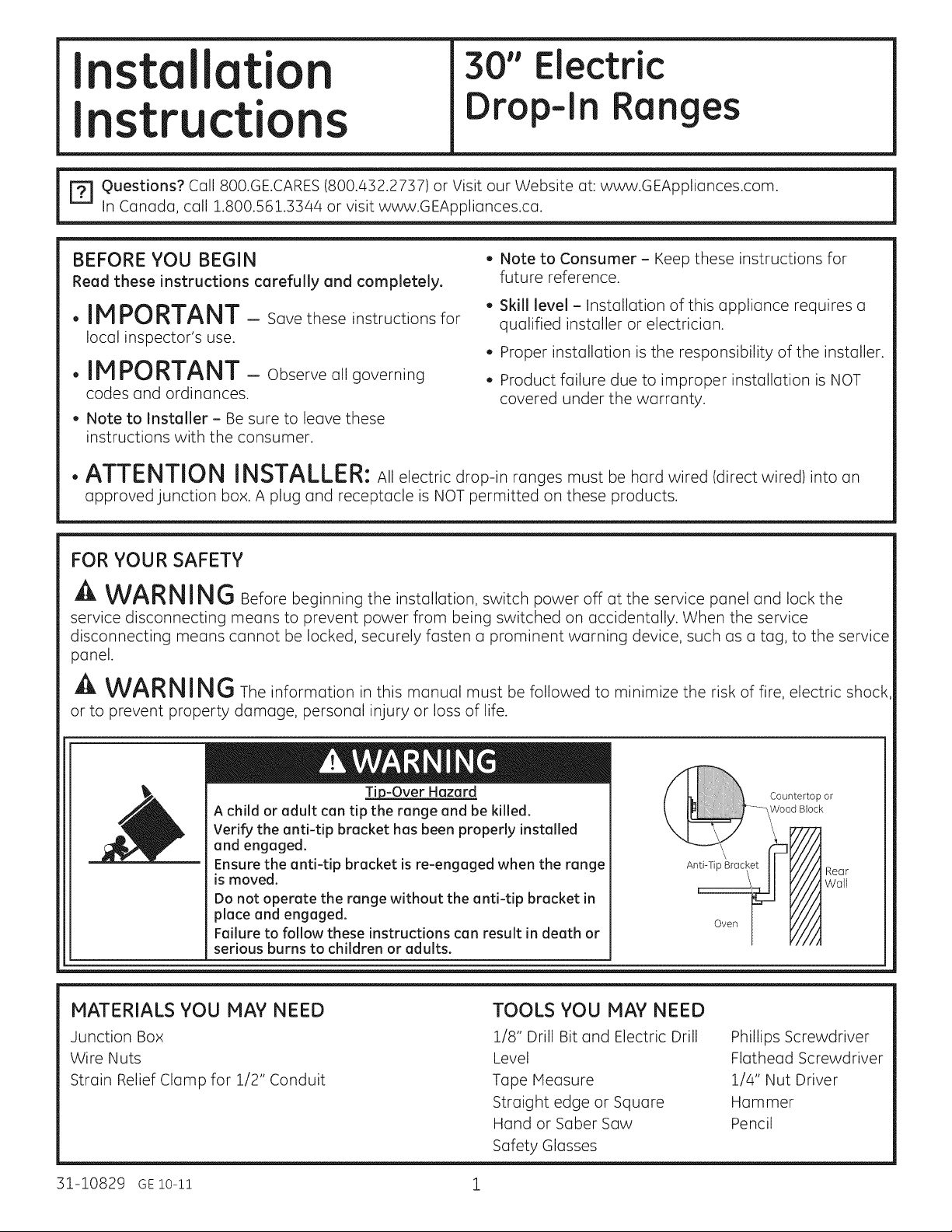
A child or adult can tip the range and be killed.
Verify the anti-tip bracket has been properly installed
and engaged.
Ensure the anti-tip bracket is re-engaged when the range
is moved.
Do not operate the range without the anti-tip bracket in
place and engaged.
Failure to follow these instructions can result in death or
serious burns to children or adults.
MATERIALS YOU MAY NEED
Junction Box
Wi re Nuts
Strain Relief Clamp for 1/2" Conduit
p-Over Hazard
Anti-T
Oven
TOOLS YOU MAY NEED
1/8" Drill Bit and Electric Drill
Level
Tape Measure
Straight edge or Square
Hand or Saber Saw
Safety Glasses
Countertop or
Wood Block
IIII Rear
///I
////Wall
Y/#
Phillips Screwdriver
Flathead Screwdriver
1/4" Nut Driver
Hammer
Pencil
31-10829 GElO-ll 1
Page 2
Installation Instructions
| REMOVE PACKAGING MATERIALS
Failure to remove packaging materials could result in damage to the appliance. Remove all packing parts from
oven, racks, and heating elements. Remove protective film and labels on the outer door and control panel.
Also remove plastic on trims and panel and all tape around the oven. Open oven door and remove literature
pack and oven racks. Remove the bottom trim from the side of the oven. It will be installed at the end of the
installation process. The trim is wrapped separately in a plastic bag which will also contain the 4 screws to
secure the bottom trim and the 2 shoulder screws used to secure the product to the cabinet.
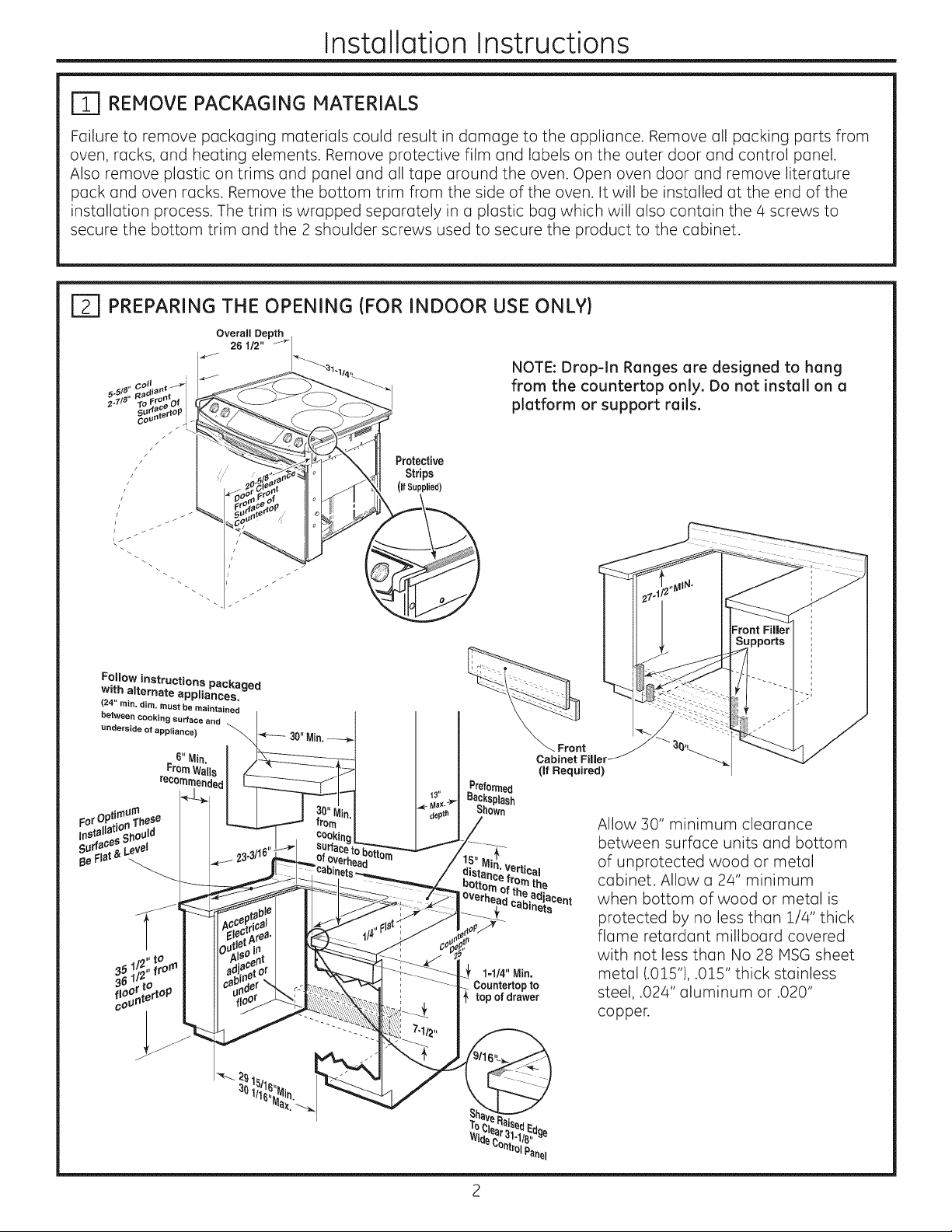
IT] PREPARING THE OPENING (FOR INDOOR USE ONLY)
Overall Depth
26 1/2"
NOTE: Drop-In Ranges are designed to hang
from the countertop only. Do not install on a
platform or support rails.
Protective
Strips
(If Supplied)
Fellow instructions packaged
with alternate appliances.
(24" rain, dim, must be maintained
between COoking surface and
underside of appliance)
6"
recom
ertical
Front
(If Required)
the
Allow 30" minimum clearance
between surface units and bottom
of unprotected wood or metal
cabinet. Allow a 24" minimum
when bottom of wood or metal is
protected by no less than 1/4" thick
flame retardant millboard covered
with not less than No 28 P1SGsheet
metal (.015"), .015" thick stainless
steel, .024" aluminum or .020"
copper.
2
Page 3
Installation Instructions
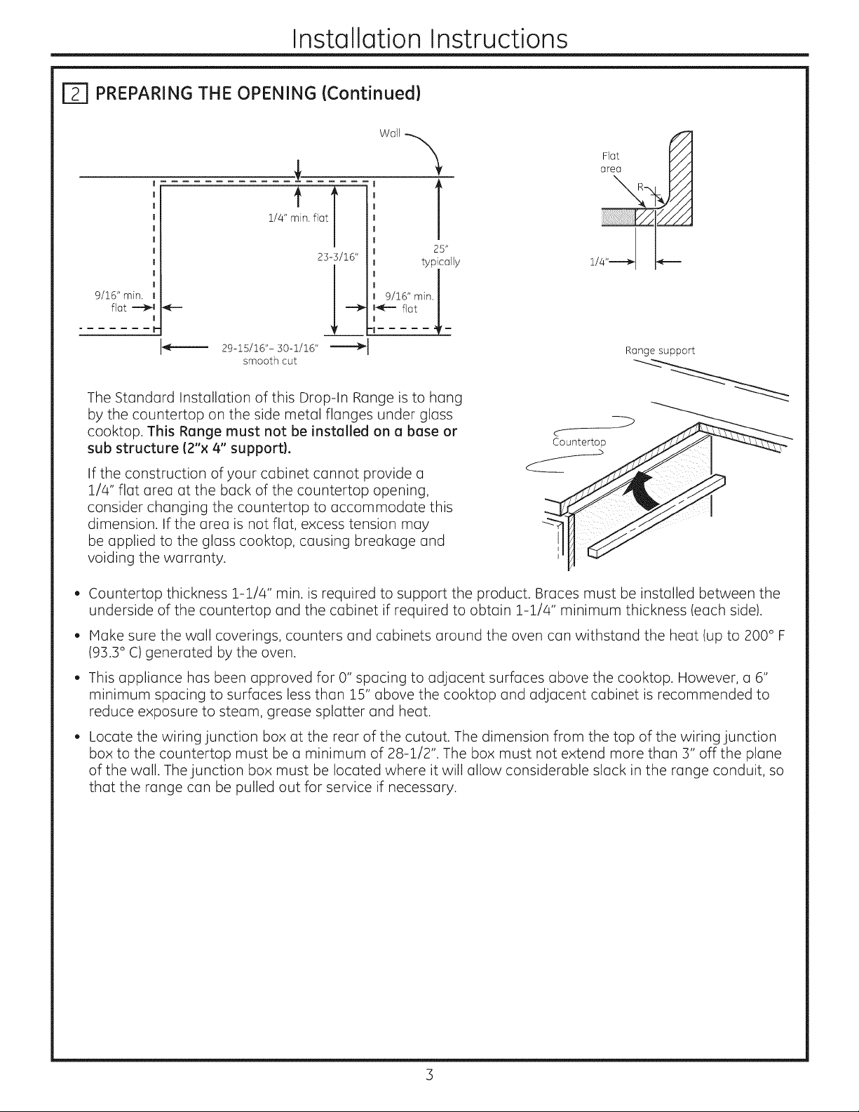
E] PREPARING THE OPENING (Continuedl
FJot
area R _-'/A
1/4" m_in. fiat T
23-3/16"
9/16" min.
fiat _
I
P
29-15/16"- 30-1/16"
smooth cut
The Standard Installation of this Drop-In Range is to hang
by the countertop on the side metal flanges under glass
cooktop. This Range must not be installed on a base or
sub structure (2"× 4" support).
If the construction of your cabinet cannot provide a
1/4" flat area at the back of the countertop opening,
consider changing the countertop to accommodate this
dimension. If the area is not flat, excess tension may
be applied to the glass cooktop, causing breakage and
voiding the warranty.
Countertop thickness 1-1/4" min. is required to support the product. Braces must be installed between the
underside of the countertop and the cabinet if required to obtain 1-1/4" minimum thickness (each side).
1-
9/16" min. I
1
25"
typically
1/4"-......._ p-.--
Range support
C
Countertop
Make sure the wall coverings, counters and cabinets around the oven can withstand the heat (up to 200 ° F
(93.3° C)generated by the oven.
Thisappliance has been approved for 0" spacing to adjacent surfaces above the cooktop. However, a 6"
minimum spacing to surfaces less than 15" above the cooktop and adjacent cabinet is recommended to
reduce exposure to steam, grease splatter and heat.
Locate the wiring junction box at the rear of the cutout. The dimension from the top of the wiring junction
box to the countertop must be a minimum of 28-1/2". The box must not extend more than 3" off the plane
of the wall. The junction box must be located where it will allow considerable slack in the range conduit, so
that the range can be pulled out for service if necessary.
3
Page 4
Installation Instructions
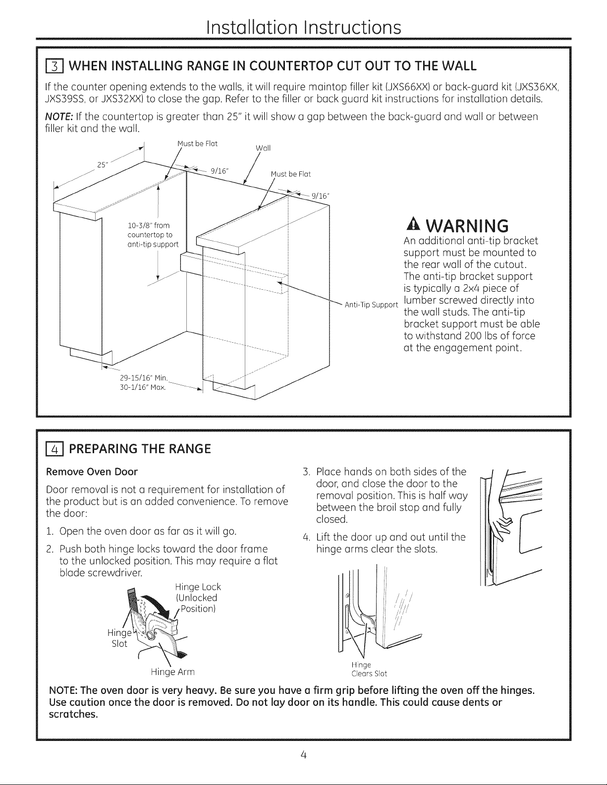
r_ WHEN INSTALLING RANGE IN COUNTERTOP CUT OUT TO THE WALL
If the counter opening extends to the walls, it will require maintop filler kit (JXS66XX) or back-guard kit (JXS36XX,
JXS39SS, or JXS32XX) to close the gap. Refer to the filler or back guard kit instructions for installation details.
NOTE: If the countertop is greater than 25" it will show a gap between the back-guard and wall or between
filler kit and the wall.
Hust be Flat
Wall
10-3/8" from
countertop to
anti-tip support
b
r_ PREPARING THE RANGE
9/16"
Hust be Flat
"_ Anti-Tip Support
WARNING
An additional anti-tip bracket
support must be mounted to
the rear wall of the cutout.
The anti-tip bracket support
is typically a 2x4 piece of
lumber screwed directly into
the wall studs. The anti-tip
bracket support must be able
to withstand 200 Ibs of force
at the engagement point.
Remove Oven Door
Door removal is not a requirement for installation of
the product but is an added convenience. To remove
the door:
.
Open the oven door as far as it will go.
2.
Push both hinge locks toward the door frame
.
Place hands on both sides of the
door, and close the door to the
removal position. This is half way
between the broil stop and fully
closed.
.
Lift the door up and out until the
hinge arms clear the slots.
to the unlocked position. This may require a flat
blade screwdriver.
Hin(
Slot
Hinge Lock
(Unlocked
/Position)
Hinge Arm Clears Slot
Hinge
/ ,
/
//'/
NOTE: The oven door is very heavy. Be sure you have a firm grip before lifting the oven offthe hinges.
Use caution once the door is removed. Do not lay door on its handle. This could cause dents or
scratches.
Page 5
Installation Instructions
| ELECTRICAL REQUIREMENTS
A WARNING Electric Shock Hazard
. This appliance must be properly grounded.
. Do not use an extension cord.
Before installing range, switch power off at the service panel and lock the service disconnecting means
to prevent power from being switched on accidentally. When the disconnection means cannot be locked,
securely fasten a prominent warning device, such as a tag, to the service panel.
Failure to follow these instructions may result in serious injury or death.
A WARNING Fire Hazard
Improper connection of aluminum house wiring to copper leads can result in an electrical or fire hazard. If
residence leads are aluminum, use only connectors designed for joining copper to aluminum and follow the
manufacturer's recommended procedure closely. Failure to do so may result in serious injury or death.
We recommend you have the electrical wiring and hookup of the appliance connected by a qualified
electrician. After installation, have the electrician show you how to disconnect power from the appliance.
You must use a single-phase, 120/208 VAC or 120/240 VAC, 60 Hertz electrical system.
Effective January 1, 1996, the National Electrical Code requires that new construction (not existing) utilize a
four-conductor connection to an electric oven. When installing an electric oven in new construction, a mobile
home, recreational vehicle or area where local codes prohibit grounding through the neutral conductor, refer
to the section on four-conductor branch circuit connections.
Check with your local utilities for electrical codes which apply in your area. Failure to wire your oven according
to governing code could result in a hazardous condition. If there are no local codes, your oven must be wired
and fused to meet the National Electrical Code, NFPA No. 70-latest edition, available from the National Fire
Protection Association.
Rating plate is located on oven front frame and is visible when oven door is open.
This appliance must supplied be with the proper voltage and frequency, and connected to an individual,
properly grounded, 40 amp (minimum) branch circuit protected by a circuit breaker or time-delay fuse.
DO NOT shorten the flexible conduit. The conduit strain relief clamp must be securely attached to the junction
box and the flexible conduit must securely attached to the clamp. If the flexible conduit will not fit within the
clamp, do not install the oven until a clamp of the proper size is obtained.
The 3 power leads supplied with this appliance are suitable for connection to heavier gauge household
wiring. The insulation of these 3 leads is rated for temperatures much higher than the temperature rating of
the household wiring. The current-carrying capacity of the conductor is governed by the wire gauge and the
temperature rating of the insulation around the wire.
5
Page 6
Installation Instructions
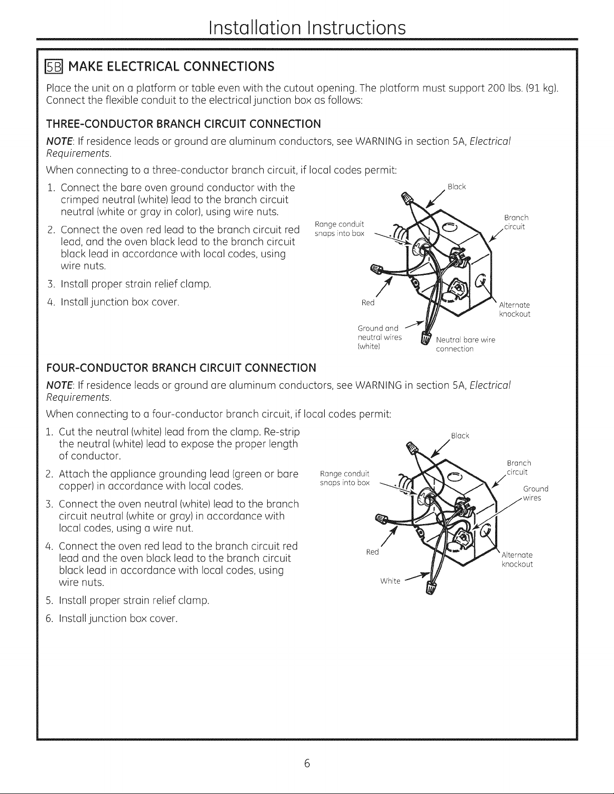
MAKE ELECTRICAL CONNECTIONS
Place the unit on a platform or table even with the cutout opening. The platform must support 200 Ibs. (91 kg).
Connect the flexible conduit to the electrical junction box as follows:
THREE-CONDUCTOR BRANCH CIRCUIT CONNECTION
NOTE: If residence leads or ground are aluminum conductors, see WARNING in section 5A, Electrical
Requirements.
When connecting to a three-conductor branch circuit, if local codes permit:
1. Connect the bare oven ground conductor with the
crimped neutral (white)lead to the branch circuit
neutral (white or gray in color), using wire nuts.
2. Connect the oven red lead to the branch circuit red
lead, and the oven black lead to the branch circuit
black lead in accordance with local codes, using
wire nuts.
Range conduit
snaps into box
Black
Branch
/circuit
3. Install proper strain relief clamp. /
/
4. Install junction box cover. Red
Ground and
neutral wires Neutral bare wire
(white) connection
FOUR-CONDUCTOR BRANCH CIRCUIT CONNECTION
NOTE: If residence leads or ground are aluminum conductors, see WARNING in section 5A, Electrical
Requirements.
When connecting to a four-conductor branch circuit, if local codes permit:
1. Cut the neutral (white) lead from the clamp. Re-strip Black
the neutral (white)lead to expose the proper length
of conductor.
2. Attach the appliance grounding lead (green or bare
copper) in accordance with local codes.
3. Connect the oven neutral (white) lead to the branch
_"<__L _ rV X_ Grouna
1
circuit neutral (white or gray)in accordance with
local codes, using a wire nut.
4. Connect the oven red lead to the branch circuit red
lead and the oven black lead to the branch circuit
_ knockout
black lead in accordance with local codes, using
wire nuts.
White
Alternate
knockout
5. Install proper strain relief clamp.
6. Install junction box cover.
Page 7
Installation Instructions
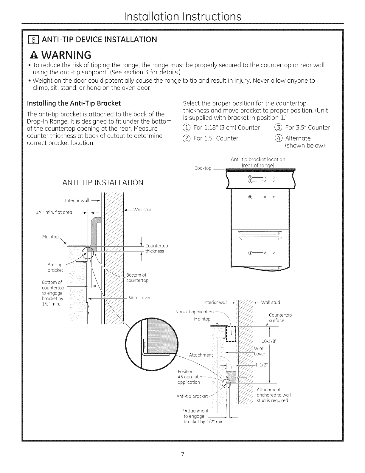
F_ ANTI-TIP DEVICE INSTALLATION
WARNING
. To reduce the risk of tipping the range, the range must be properly secured to the countertop or rear wall
using the anti-tip suppport. (See section 3 for details.)
. Weight on the door could potentially cause the range to tip and result in injury. Never allow anyone to
climb, sit, stand, or hang on the oven door.
Installing the Anti-Tip Bracket
The anti-tip bracket is attached to the back of the
Drop-In Range. It is designed to fit under the bottom
of the countertop opening at the rear. Measure
counter thickness at back of cutout to determine
correct bracket location.
ANTI-TIP INSTALLATION
Interiorwall -_
1/4" min.flat area
_-- Wall stud
Countertop
thickness
t
Anti-ti
bracket
Bottom of
countertop --
to engage
bracket by
1/2" min.
__ Wire cover
Bottom of
countertop
Select the proper position for the countertop
thickness and move bracket to proper position. (Unit
is supplied with bracket in position 1.)
(_ For 1.18" (3 cm) Counter (_ For 3.5" Counter
(_ For 1.5" Counter (_ Alternate
(shown below)
Anti-tip bracket location
Cooktop
(rear of range)
I
Interior wall
Non-kit application
Maintop \ _,
............Wallstud
Countertop
surface
Attachment
Position
#5
application
Anti-tip
*Attachment
to engage
bracket by 1/2" min.
10-5/8"
Wire
Attachment
anchored to wall
stud is required
Page 8
Installation Instructions
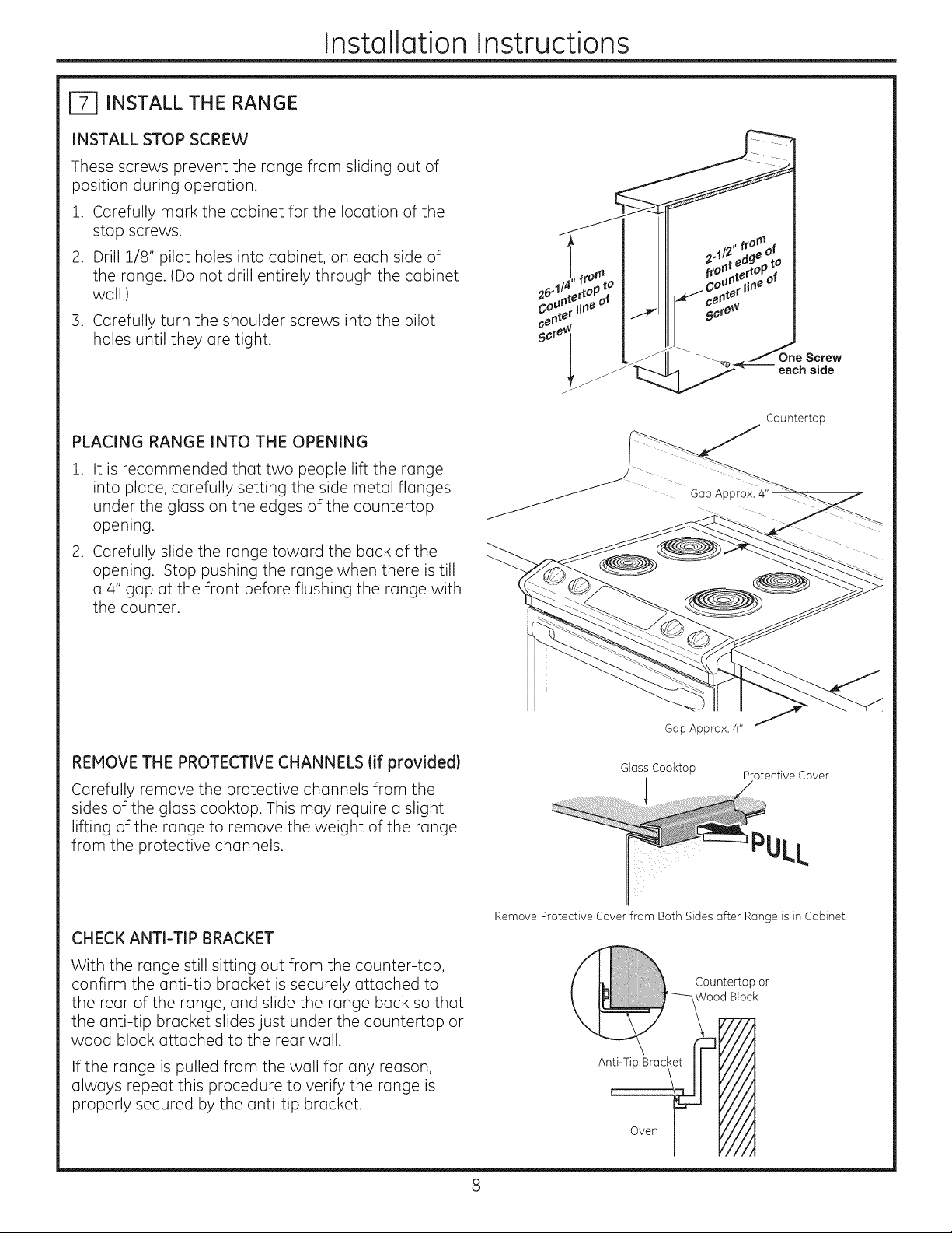
El INSTALL THE RANGE
INSTALL STOP SCREW
These screws prevent the range from sliding out of
position during operation.
.
Carefully mark the cabinet for the location of the
stop screws.
.
Drill 1/8" pilot holes into cabinet, on each side of
the range. (Do not drill entirely through the cabinet
wall.)
3. Carefully turn the shoulder screws into the pilot
holes until they are tight.
PLACING RANGE INTO THE OPENING
.
It is recommended that two people lift the range
into place, carefully setting the side metal flanges
under the glass on the edges of the countertop
opening.
.
Carefully slide the range toward the back of the
opening. Stop pushing the range when there is till
a 4" gap at the front before flushing the range with
the counter.
Countertop
REMOVETHE PROTECTIVECHANNELS (if provided}
Carefully remove the protective channels from the
sides of the glass cooktop. This may require a slight
lifting of the range to remove the weight of the range
from the protective channels.
CHECK ANTI=TIP BRACKET
With the range still sitting out from the counter-top,
confirm the anti-tip bracket is securely attached to
the rear of the range, and slide the range back so that
the anti-tip bracket slides just under the countertop or
wood block attached to the rear wall.
If the range is pulled from the wall for any reason,
always repeat this procedure to verify the range is
properly secured by the anti-tip bracket.
Gap Approx. 4"
Glass Cooktop Protective Cover
PULL
Remove Protective Cover from Both Sides after Range is in Cabinet
Page 9

Installation Instructions
E_ INSTALL THE RANGE (Continued)
ATTACH THE LOWER TRIM
Attach the lower trim (supplied separately with the
range) to the bottom of the vertical side trim with the
4 screws supplied.
LOCATING THE STOP SCREW
Carefully slide the range towards the back of the
opening. When the range is approximately 1" from
the back of the opening, lift the front of the range
approximately 1W'to clear the stop screw located
in the sides of the cabinet. Slide the range until it is
seated into the opening.
Lower the front of the range onto the counter-top.
CHECK FOR PROPER INSTALLATION OF THE STOP SCREW
Look at both sides of the range under the door. The
stop screws must be located in the notch on the
sides of the range, and not touch the top of the notch
when the range is fully seated on the countertop. If
the screws do not meet the requirements, move the
screws to a position that meets these requirements.
(See illustration.)
Lower
Trim
Lower
Attoch 2
screws right
eoch end of
front
frame
C,ear o
REPLACING THE OVEN DOOR
Remove Oven Door
.
Lift the oven door by placing one
hand on each side. the door is
heavy, so you may need help. Do
not lift the door by the handle.
Shoulder
Screw
. With the door at the same
angle as the removal
position (halfway between
the closed and broil stop
position) seat the notch
of the hinge arm into the
bottom edge of the hinge
slot. The notch of the hinge
arm must be fully seated
into the bottom of the seat.
Bottom
Edge of
Slot '
Notch in Bottom
of Side Trim
Hinge Arm
Hinge Notch
Page 10

Installation Instructions
[_ REPLACING THE OVEN DOOR (Continued)
3. Open the door as far as it will open. Push the
hinge lock up against the front frame of the oven
cavity, to the locked position. Close the door.
Notch of Hinge
Securely Fitted
into Bottom of
Hinge Slot
F_ FINAL CHECKLIST
, Check to make sure the circuit breaker is closed (Reset) or the circuit fuses are replaced.
. Be sure power is in service to the building.
. Check to be sure that all packing materials and tape have been removed. Failure to remove these materials
could result in damage to the appliance once the appliance has been turned on and surface elements have
heated
Hinge in Locked
Position
OPERATION CHECKLIST
. Check to make sure the Clock display isenergized. If a series of horizontal red lines appear in the display,
disconnect power immediately. Recheck the range wiring connections. If change is made to connections,
retest again. If no change is required, have building wiring checked for proper connections and voltage. It is
recommended that the clock be changed if the red lines appear.
, Push down and turn any one of the four surface knobs to "HED" setting to observe that the element glows
within 15 seconds. Turn the knob off when glow is detected. If the glow is not detected within the time limit,
recheck the range wiring connections. If change is required, retest again. If no change is required, have
building wiring checked for proper connections and voltage.
10
Page 11

Notes
11
Page 12

12 Printed in the United States
Page 13

Instrucc"
de i stal
Cocinas encastrables
de 30"
ANTES DE COMENZAR
Lea estas instrucciones por completo y con
detenimiento.
oIMPORTANTE - Guardeestas
instrucciones para el uso de inspectores locales.
.IN PORTANTE - Cumplacontodoslos
c6digos y ordenanzas vigentes.
, Nota al instalador -AsegQrese de dejar estas
instrucciones con el consumidor.
. ATENCI6N INSTALADOR: Todas las cocinas encastrables el6ctricas deben contar con
cableado de conexi6n permanente (cableado directo) dentro de una caja de conexiones aprobada. En estos
productos NO se permite la conexi6n del tipo "enchufe y recept6culo".
PARA SU SEGURIDAD
Nota al consumidor - estas instrucciones para
referencia futura.
Nivel de destreza - La instalaci6n de este aparato
requiere el trabajo de un instalador o electricista
calificados.
o
Elinstalador tiene la responsabilidad de efectuar
una instalaci6n adecuada.
La garant[a no cubre las fallas del producto
provocadas por una instalaci6n incorrecta.
A ADVERTENCIA Antes de comenzar la instalaci6n, desconecte la energia del panel de servicio y
bloquee los medios de desconexi6n para evitar el accionamiento de laenergia de manera accidental. Cuando los
medios de desconexi6n de servicio no pueden bloquearse, coloque sobre el panel de servicio un dispositivo de
advertencia bien visible, como una etiqueta.
A ADVERTENCIA La informaci6n de este manual debe seguirse al pie de la letra a fin de minimizar e
riesgo de incendios, descargas el6ctricas, o para prevenir da_os a la propiedad, lesiones personales o la muerte.
de Volcaduras
Un niSo o adulto pueden volcar la cocina y morir.
Instale el dispositivo anti-volcaduras (tornillos o soporte)
de acuerdo con las siguientes instrucciones.
Vuelva a colocar el soporte anti-volcaduras si la estufa
se mueve de lugar.
Siestas instrucciones no se siguen, como resultado se podr6
producir la muerte o quemaduras graves de niffos y adultos.
MATERIALES QUE PUEDE NECESITAR
Caja de conexiones
Tapones de alambre
Abrazadera de alivio de tensi6n para conducto de 1/2"
31-i0829 GEi0-ii 1
Base o Bbque
---_e Nadera
oote
HERRAMIENTAS NECESARIAS
Broca de perforadora de 1/8"y perforadora el6ctrical
Destornillador de estrella
Destornillador con punta plana
Llave de tuercas de 1/4"
Punta derecha o cuadrada
Sierra de mano o sierra sable
Nivel
Cinta m6trica
Martillo
L6piz
Gafas de Seguridad
Page 14

Instrucciones de instalaci6n
rT] QUITE LOS MATERIALES DE EMPAQUE
empaque del homo, bandejas y elementos de calentamiento. Quite la pelicula protectora y los etiquetas de la
puerto exterior y panel de control. Adem6s, quite el pldstico de los rebordes y panel y toda la cinta colocada
alrededor del horno. Abra la puerto del homo y quite el material informativo y los bandejas del horno. Quite
el reborde inferior de la porte lateral del horno. Se colocar6 al final del proceso de instalaci6n. El borde est6
envuelto de forma aparte en una balsa plastica que tambi6n contendr6 4 tornillos para asegurar el borde
inferior y los tornillos de tope usados para asegurar el producto al gabinete.
[_ PREPARE LA ABERTURA (S6LOPARA USO EN EL INTERIOR)
Profundidad total
de 26-I/2"
5-5/8" Bobina
hasta la superficie
frontal de la base
Siga los instrucciones embaladas
con los electrodom_sticos alternativos.
(Sedeber6 mantener unadim. rain.
de 2z¢"entre la superficie de la cocina
y el lado inferior del electrodom_stico
Se recomienda un rain.
De 6" desde los paredes
Para una instalaci6n 6prima,
estas superficies deber6
ser pianos y estar a nivel
35 _/2"a
56 _/2"desde Mfn.de i-i/4"
la puerto desde la base
hasta a la porte superior
la base delcaj6n
Min. de 30" _
Franjas
de protecci6n
(si se surninistran)
Profundidad
NOTA: Las cocinas empotrables son diseSadas
para colgar de la base 6nicamente. No instale
sobre una plataforma de rieles con soportes.
Huestro
delTaMero
Posterior
Preformado
Distancia vertical mfn. 15"
desde la porte inferior
de los gabinetes adyacentes
dad
deIo base
Afeitor borde levantodo
para eliminar 31-1/8"
de ancho del panel
Relleno
delgaNnete
frontal
(si se requiere)
Deje un espacio minima de 30"
entre los unidades de la superficie
y la porte inferior del gabinete de
madera o metal sin protecci6n. Deje
un espacio minima de 24" cuando
la porte inferior de la madera o
metal est6n protegidas par cart6n
de retardo de incendios de 1/4" de
grosor, cubierto con no menos que
una hoja de acero inoxidable N° 28
MGS de 0.15", de aluminio de 0.24" o
de cobre de .020" de grosor.
2
Page 15

Instrucciones de instalaci6n
E] PREPARE LA ABERTURA (Continuaci6n)
Pared %
Mh, d! ¼" l
l
piano /
23-3/16"
H[n. de 9/16"
piano
La Instalaci6n Est6ndar de esta Estufa Empotrable es colgando
de la base sabre la pestafla met61ica lateral debajo de la
cocina de vidrio. Esta Estufa no deber_ ser instalada sabre
una base o subestructura (soporte de 2" x 4"1.
Sila construcci6n de su gabinete no puede brindar un 6rea
plana de 1A"en la parte trasera de la abertura de la base,
considere la posibilidad de cambiar la base para que se
acomode a esta dimensi6n. Si el 6tea no es plana, se podr6
aplicar tensi6n excesiva a la cocina de vidrio, ocasionando
roturas y anulando la garantia.
|
Corte parejo de
29-15/16"-30-1/16"
l Min. de 9/16 I
-'_r'a:o_l
Tfpicamente
de 25"
Area
piano R
Soporte de la estufa
Base
Se requiere un grosor de la base min. de 1-1/4" para el soporte del producto. Se deber6n instalar
abrazaderas entre el lado inferior de la base y el gabinete, si se requiere obtener un grosor min. de 1-1/4"
(en cada lado).
AsegOrese de que los cobertores de pared, bases y gabinetes alrededor del horno puedan resistir el calor
(hasta 200 ° F/93.3 ° C)generado por el horno.
Esteaparato ha sido aprobado para un espacio de 0" respecto de superficies adyacentes sabre la estufa.
Sin embargo, se recomienda un espacio minima de 6" respecto de superficies menores a 15" sabre la
estufa y gabinete adyacente para reducir la exposici6n al vapor, salpicaduras de grasa y color.
Ubique una caja de conexiones de cableado en la parte trasera del recorte. La dimensi6n desde la porte
superior de la caja de conexiones hasta el mostrador debe set de un minima de 28-1/2". La caja no debe
extenderse me%de 3" del piano de la pared. La caja de conexiones debe ubicarse en un lugar en donde
permita una holgura considerable en el conducto de la cocina, para que 6sta pueda moverse a fin de
efectuar reparaciones si fuera necesario.
3
Page 16

Instrucciones de instalaci6n
[_ CUANDO INSTALE LA COCINA EN UN MOSTRADOR QUE TIENE UN
RECORTE EN LA PARED
Sila abertura de la base se extiende hasta las paredes, requerir6 un kit de relleno de la base de la parte
superior (JXS66XX)o un kit de protecci6n trasera (JXS36XX,JXS39SSo JXS32XX)para cerrar la brecha. Para
acceder a detalles de la instalaci6n, consulte el kit de relleno o de protecci6n trasera.
NOTA: Si la base es superior a 25", mostrar6 una brecha entre la protecci6n trasera y la pared o entre el kit de
relleno y la pared.
Deber6 ser plana Pared
10-5/8"
la mesada hasta
el soporte
anti-votcaduras
N6× de 30 -1/16_-_
9/16"
Deber6 ser plana
PREPARE LA COCINA
Quite ia puerta dei homo
No es un requisito que se retire la puerta para la
instalaci6n del producto, pero es conveniente. Para
retirar la puerta:
1. Abra la puerta del homo tanto como sea posible.
.
Empuje ambas trabas de las bisagras hacia el
marco de la puerta hasta la posici6n destrabada.
Esto podr6 requerir el uso de un destornillador de
punta plana.
116"
A ADVERTENCIA
Se deber6 montar un soporte
anti-volcaduras adicional sobre
la pared trasera de la abertura.
El soporte anti-volcaduras
es tipicamente una pieza de
---'- Soporte
anti-votcaduras
.
Coloquelas manos sobre ambos
ladosde la puerta, y cierre la misma
en la posici6n para su retiro. Esto
seencuentra entre la posici6n de
detenimiento de la funci6n de asar a
la parrilla y totalmente cerrado.
4.
Levante la puerta hacia arriba y
afuera, hasta que los brazos de las
bisagras despejen las ranuras.
madera de 2 x 4 que se atornilla
directamente en montajes
de pared. El soporte anti-
volcaduras deber6 poder resistir
200 libras de fuerza en el punto
de adhesi6n.
_ Hinge Lock
(Unlocked
_!_ _. /Position
Hin_:,_ ,_/_.I
Hinge Arm
Bisagra despe]e
de ]a ranura
//
NOTA: La puerta del horno es muy pesada. AsegOrese de tomar la misma de manera firme, quitando
la mJsma de las bJsagras. Tenga cuidado una vez que la puerta haya sJdo retJrada. No apoye la puerta
sobre su manJja. Esto podria ocasJonar abolladuras o rayaduras.
Page 17

Instrucciones de instalaci6n
REQUISITOS ELI_CTRICOS
A ADVERTENCIA Riesgode descerga el_ctrica
, Este aparato debe contar con una adecuada conexi6n a tierra.
. No utilice un cable de extensi6n.
. Antes de comenzar la instalaci6n, desconecte la energia del panel de servicio y bloquee los medios de
desconexi6n para evitar el accionamiento de la energia de manera accidental. Cuando los medios de
desconexi6n de servicio no pueden bloquearse, coloque sobre el panel de servicio un dispositivo de
advertencia bien visible, como una etiqueta.
No seguir estas instrucciones puede provocar una lesi6n grave o la muerte.
A ADVERTENCIA Riesgo de incendio
Una conexi6n inadecuada de cableado dom6stico de aluminio con cables de cobre puede generar un peligro
el6ctrico o un incendio. Si los cables dom6sticos son de aluminio, s61o use conectores dise_ados para unir
cobre con aluminio y siga al pie de la letra el procedimiento recomendado del fabricante. No hacerlo puede
provocar una lesi6n grave o la muerte.
Recomendamos que un electricista calificado conecte el cableado el6ctrico de su aparato. Despu6s de la
instalaci6n, solicite al electricista que le indique c6mo desconectar la energia del aparato.
Usted debe usar un sistema el6ctrico de fase Onica de 120/208 VAC o 120/240 VAC de 60 hercios.
Vigente desde el 1 de enero de 1996, el C6digo EI6ctrico Nacional requiere que las nuevas construcciones
(no existentes) utilicen una conexi6n de cuatro conductores a un homo el6ctrico. Cuando instale un homo
el6ctrico en una construcci6n nueva, una casa rodante, un vehiculo recreativo o un 6rea donde los c6digos
locales prohiben la conexi6n a tierra a trav6s de un conductor neutral, consulte la secci6n sobre conexiones
en circuito derivado de cuatro conductores.
Consulte alas empresas de servicio pOblico sobre los c6digos el6ctricos que se aplican en su 6rea. No realizar
el cableado de su homo de acuerdo con los c6digos vigentes puede provocar una situaci6n peligrosa. Si no
existen c6digos locales, el cableado y fusibles de su homo deben cumplir con el C6digo EI6ctrico Nacional,
NFPA N° 70, Oltima edici6n, disponible en National Fire Protection Association (Asociaci6n Nacional de
Protecci6n contra Incendios).
La placa de clasificaci6n se encuentra en el armaz6n frontal del homo yes visible cuando se abre la puerta
del horno.
Este electrodom6stico debe recibir el voltaje y frecuencia adecuados, y debe conectarse a un circuito derivado
individual con adecuada conexi6n a tierra de 40 amperios (minimo) protegido por un interruptor de circuitos o
fusible con retraso.
NO acorte el conducto flexible. La abrazadera del alivio de tensi6n del conducto debe estar bien sujeta a la
caja de conexiones y el conducto flexible debe estar bien sujeto a la abrazadera. Siel conducto flexible no
entra dentro de la abrazadera, no instale el homo hasta obtener una abrazadera del tama_o adecuado.
Los Z cables de energia suministrados con este aparato son adecuados para conexiones con cableados
dom6sticos de calibre mayores. La aislaci6n de estos 3 cables est6 clasificada a temperaturas mucho m6s
elevadas que la clasificaci6n del cableado dom6stico. La capacidad de transmitir corriente del conductor est6
determinada por el calibre del cable y la clasificaci6n de temperatura de la aislaci6n alrededor del cable.
5
Page 18

Instrucciones de instalaci6n
REALICE LAS CONE×IONES ELI_CTRICAS
Coloque el horno sabre una mesa o plataforma en forma nivelada con la abertura. La plataforma debe poder
soportar 200 Ibs. (91 kg). Conecte el conducto flexible a la caja de conexiones el#ctrica coma se indica abajo.
CONEXI6N DE ClRCUITO DERIVADO DE TRES CONDUCTORES
NOTA: Si los cables dom6sticos o de conexi6n a tierra son conductores de aluminio, ver la ADVERTENCIA de la
secci6n 5a, Requisitos eldctricos.
Cuando conecte un circuito derivado de tres conductores, si Io permiten los c6digos locales:
1. Conecte el conductor a tierra del horno con el Negro
cable neutral (blanco) en rizo al neutral del circuito
derivado (blanco o gris) utilizando un tap6n de
alambre, ramificado
2. Conecte el cable rojo del horno al cable rojo del
circuito derivado y el cable negro del horno al
cable negro del circuito derivado de acuerdo con
los c6digos locales, utilizando tapones de alambre.
3. Instale una abrazadera adecuada de alivio de
tensi6n.
4. Instale la tapa de la caja de conexiones. Cables a
Eltubode la estufa
seajusta enla caja
/
Rojo
y neutrales Cable neutral
(blanco) cone×i6n
Circuito
Agujero ciego
alternativo
CONEXI6N DE ClRCUITO DERIVADO DE CUATRO CONDUCTORES
NOT,A: Si los cables dom6sticos o de conexi6n a tierra son conductores de aluminio, ver la ADVERTENCIA de la
secci6n 5a, Requisitos eldctricos.
Cuando conecte un circuito derivado de cuatro conductores, si Io permiten los c6digos locales:
i. Carte el cable neutral (blanco) del conector de
engarce. Pele el cable neutral (blanco) para
exponer la Iongitud correcta del conductor.
2. Conecte el cable a tierra del aparato (verde o
cobre) de acuerdo con los c6digos locales.
3. Conecte el cable neutral (blanco) del horno con
el neutral de circuito derivado (blanco o gris) de
acuerdo con c6digos locales, utilizando un tap6n
de alambre.
4. Conecte el cable rojo del horno al cable rojo del
circuito derivado y el cable negro del homo al
cable negro del circuito derivado de acuerdo con
los c6digos locales, utilizando tapones de alambre.
_'etaUjbu°tdaee'a'CaStcUla"_'_/__ %_ _¢/" Cab,esa
-1 C _ _M_ tierra
Blanc°'_'_//_,ljl
Negro
i
_j _ alternativo
5. Instale una abrazadera adecuada de alivio de
tensi6n.
6. Instale la tapa de la caja de conexiones.
Page 19

Instrucciones de instalaci6n
r_ INSTALACION DEL DISPOSITIVO ANTI-VOLCADURAS
ADVERTENCIA
, A fin de reducir el riesgo de volcaduras de la estufa, la misma deberd estar correctamente asegurada a la
base o la pared trasera usando un soporte anti-volcaduras. (Para mds detalles, consulte la secci6n 3).
, El peso sobre la puerta podria potencialmente hacer que la estufa se vuelque y que esto produzca lesiones.
Nunca permita que nadie se trepe siente, pare ni cuelgue de la puerta del horno.
Instalaci6n de los Soportes Anti-Volcaduras
El soporte anti-volcaduras se encuentra adherido
a la parte trasera de la Cocina Empotmble. Fue
diseflado para su ubicaci6n debajo de la abertura de
la base en la parte tmsera, lvlida el grosor de la base
en la parte tmsera de la abertum para determinar la
ubicaciOn correcta del soporte.
INSTALACI6N DEL DISPOSITIVO
ANTI-VOLCADURAS
Pared interior_
Espacio piano m[n.-----_
de 1/4"
Base en la
parte superior
\
Montaje
de pared
i @rosorde la
base
t
Soporte ant
volcaduras
Parte inferior
Parte
inferior del
soporte anti-
voicaduras
para colocar
el soporte a
un rain. de
1/2"
__ Cubre cables
de la base
Seleccione la posici6n correcta de acuerdo al grosor de
la base y mueva el soporte hasta la posici6n adecuada.
(Launidad se entrega con el soporte en la posici6n 1).
(_ Paraunabasede 1.18"(Bcm.) (_) Para una basede 3.5"
(_) Para una base de 1.5" C)Alternativa (semuestra
a continuaci6n)
Ubicaci6n del soporte anti-volcaduras
Estufa
(partetrasera de la cocina)
I
__ 7
INSTALACI6N ALTERNATIVA DEL
DISPOSITIVO ANTI-VOLCADURAS
Aplicaci6n sin kit
Base en la par_.
superior
Pared interi_
............Montaje de pared
J
Superficie de
la mesada
Adhesi6n
Aplicaci6n
sin kit en
posici6n 5
Soporte
* Adhesi6n para coloca_
el soporte a un m[n. de V2"
10-3/8"
CL,
Serequiere
colocar la
adhesi6n aJ
montaje de
pared
Page 20

Instrucciones de instalaci6n
r_ INSTALALACI6N DE LA COCINA
INSTALACI6N DEL TORNILLO DE DETENCI6N
Estos tornillos evitan que la cocina se mueva de su
posici6n durante el funcionamiento.
1. Con cuidado, marque en el gabinete la ubicaci6n
de los tornillos de detenci6n.
.
Haga agujeros de prueba de 1/8" en el gabinete,
sobre cada lado de la cocina. (No haga el agujero
atravesando la pared del gabinete).
.
Con cuidado, gire los tornillos de tope en los
agujeros de prueba hasta que queden ajustados.
COLOCACI6N DE LA COCINA EN LA ABERTURA
.
Esrecomendable que dos personas levanten la
estufa hasta su ubicaci6n, colocando con cuidado
las pestahas met61icas laterales debajo del vidrio
sobre los extremos de la abertura de la base.
.
Con cuidado, deslice la cocina hacia la parte
trasera de la abertura. Deje de empujar la cocina
cuando aQnhaya un espacio de 4" en el frente,
antes de colocar la cocina al ras de la base.
26 1/4" desde
la base hasta
la linea central
det tornillo
sobre
cadalado
Base
RETIRELOSCANALES PROTECTORES
(si est6n incluidos)
Con cuidado retire los canales protectores a ambos
lados de la estufa de vidrio. Es posible que sea
necesario levantar levemente la cocina, a fin de quitar
el peso de la cocina sobre los canales protectores.
CONTROLE EL SOPORTE ANTI-VOLCADURAS
Con la cocina aQn apoyada en parte afuera de la
punta de la base, confirme que el soporte anti-
volcaduras est6 ajustado de forma segura a la parte
trasera de la cocina, y vuelva a deslizar esta Qltima
de modo que el soporte anti-volcaduras se deslice
debajo de la base o del bloque de madera ajustado a
la pared trasera.
Encaso de que la cocina sea empujada de la pared
por alguna raz6n, siempre repita este procedimiento
para verificar que la cocina est6 correctamente
asegurada por el soporte anti-volcaduras.
Espacio de 4" apro×.
Estufa de vidrio
Retire la tapa protectora a ambos lados una vez
que Jacocina est6 en el gabinete.
Page 21

Instrucciones de instalaci6n
E] INSTALALACI6N DE LA COCINA (Contin6a)
ADHIERA DEL BORDE INFERIOR
Adhiera el borde inferior (suministrado en forma
aparte con la cocina) a la parte inferior del borde del
lado vertical con los 2 tornillos provistos.
UBICACI6N DEL TORNILLO SUPERIOR
Con cuidado, deslice la cocina hacia la parte
trasera de la abertura. Cuando la cocina est6
aproximadamente a 1" de la parte trasera de
la abertura levante la parte frontal de la cocina
aproximadamente 1A"para retirar eltornillo superior
ubicado a ambos lados del gabinete. Deslice la cocina
hasta que se ubique en la abertura.
e
teral
Baje la parte frontal de la cocina sobre la base.
2 tornillos
acada
inferior
derecho
del marco
frontal
CONTROLE QUE LA INSTALACI6N DEL TORNILLO SUPERIOR SEA ADECUADA
Controle ambos lados de la cocina debajo de la
puerta. Los tornillos superiores debercin estar
ubicados en el agujero sabre los costados de la inferior
cocina, y no tocar la parte superior del agujero
cuando la cocina se encuentre totalmente ubicada
sabre la base. Si los tornillos no cumplen con los
requisitos, mueva los mismos a una posici6n de modo
que cumplan con los requisitos. (Vea la ilustraci6n).
Borde
Tornillo de
tope
E] REEMPLAZO DE LA PUERTA DEL HORNO
.
Levante la puerta del horno
colocando una mano a cada lado.
La puerta es pesada, de modo que
es posible que necesite ayuda. No
levante la puerta usando la manija
.
Con la puerta en el mismo
c_ngulo queen la posici6n Extreme
para retirarla (a mitad de dela \1
distancia entre la posici6n ranura
cerrada y de detenci6n para t\!_/
asar), coloque la abertura
del brazo de la bisagra en I1_
el extremo inferior de la
ranura de la bisagra. La
abertura en el brazo de Abertura de la bisagra
la bisagra deberd estar
totalmente apoyada en la parte inferior
de la ranura.
J°1
Agujero en la parte
inferior del horde
lateral
inferior Jill
I\lt
P
spaclo
Brazo de la bisagra
i
Page 22

Instrucciones de instalaci6n
ITI REEMPLAZO DE LA PUERTA DEL HORNO (Contin6a)
Abra la puerta del homo tanto como sea posible.
3- bloqueada
Empuje los bloqueos de bisagra contra la
estructura frontal de la cavidad del homo, hasta
la posici6n de bloqueo. Cierre la puerta.
Abertura de la
bisagra ajustada
en forma sec
en la parte
inferior de la
ranura de la
bisogra
I-_ LISTADO DE CONTROL FINAL
, Verifique que el interruptor de circuitos se encuentre cerrado (RESET)o que los fusibles del circuito se hayan
reemplazado.
, Aseg@ese de que haya suministro el6ctrico en el edificio.
, Aseg0rese que todos los materiales de empaque y cintas se hayan retirado. Siestos materiales no se retiran
se pueden producir como resultado un daBo sobre el electrodom6stico, una vez que el mismo rue encendido
y las superficies se calientan.
Bisagra en la posici6n
| LISTA DE CONTROL DE FUNCIONAMIENTO
. AsegOrese de que la pantalla del Reloj est6 activada. Si en la pantalla aparece una serie de lineas rojas
horizontales, desconecte la energia de inmediato. Vuelva a controlar las conexiones del cableado de la
cocina. Si se efectOa un cambio en las conexiones, vuelva a probar el aparato. Si no se requiere un cambio,
haga controlar el cableado del edificio para verificar las conexiones y voltaje adecuados. Se recomienda
cambiar el reloj si aparecen las lineas rojas.
. Empuje y gire cualquiera de las cuatro perilla de la superficie a la configuraci6n "NED" y observe si el
elemento brilla dentro de los 15 segundos. Apague la perilla cuando se detecte el brillo. Si no se detecta el
brillo dentro del tiempo limite, vuelva a controlar las conexiones de los cables de la cocina. Si se requiere un
cambio, vuelva a hacer la prueba. Si no se requiere un cambio, solicite que se controlen las conexiones y el
voltaje del cableado de la edificaci6n.
10
Page 23

Notas
11
Page 24

12 Impreso en los Estados Unidos
 Loading...