

GE JCSP38DN4BB, JCSP42SN3SS, JCSP46DP2WW, JCSP38BK1BB, PCS905DP2BB Installation Instructions Manual
...Page 1
Installation Instructions
30" Electric Slide-In Ranges
Questions? Call 1.800.561.3344orvisitwww.GEAppliances.ca
BEFORE YOU BEGIN
Read these instructions completely and carefully.
• IMPORTANT--save theseinstructionsfor local inspector'suse.
• IMPORTANT---Observe all governing codes and ordinances.
• Note to Installer - Be sureto leave these instructionswith Consumer,
• Note to Consumer - Keep these instructionsforfuture reference.
° Skill level - Installation of this appliance requires basic mechanical
skills and advanced electrical skills,
• Proper installationisthe responsibilityof the installer.
• Productfailure dueto improperinstallationisnotcoveredunderwarranty.
AWARNING: Thisapp,,ancemustbeproperly
connected by means of the suppliedcord and plug. If yourkitchen does not
have a receptacle, you must have one installed bya licensed electrician.
FOR YOUR SAFETY:
Bracket Kit
• All ranges can tip.
• BURNS or other SERIOUS
INJURIES can result.
• INSTALL and CHECK the
ANTI-TIP bracket following
the instructions supplied
with the bracket.
_ Anti-Tip
Ifyoudid notreceivean anfl-tip
call 1,800.561.3344 to receive
one at no cost.For installation
bracketwithyour purchase,
instructionsofthe bracket,
visitwww.GEAppliances.ce.
Included
AWARNING---Before beginning the installation,switch
poweroff at servicepanel and lockthe service disconnectingmeans to
prevent power from being switchedon accidentally.When the service
disconnectingmeanscannot be locked, securelyfasten a prominent
warning device,such as a tag, tothe servicepanel.
TOOLS YOU WILL NEED
Drillwith 1/8" Bit Level
Safety Glasses Tape Measure
Adjustable Wrench
Pliers
1/4" Nut Driver
w
I" •
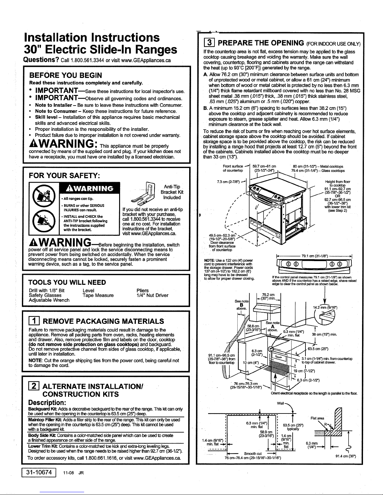
I-_ PREPARE THE OPENING (FOR INDOORUSEONLY)
If the countertoparea isnot flat,excess tension may beapplied to the glass
cooktopcausing breakage and voidingthe warranty.Make surethe wall
covedng,countertop,floodng and cabinetsaroundthe rangecan withstand
the heat (up to 93°C [200°F]) generated bythe range.
A. Allow 76.2 cm (30") minimumclearancebetween surfaceunitsand bottom
of unprotectedwood or metal cabinet, orallow a 61 cm (24") minimum
when bottomofwood or metal cabinet isprotectedby no lessthen 6.3 mm
(1/4")thick flame retardantmillboardcovered withno lessthan No. 28 MSG
sheet metal .38 mm (.015")thick, .38 mm (.015") thick stainlesssteel,
.63mm (.025")aluminum or .5mm (.020")copper.
B. A minimum15.2 cm (6")spacingto surfaceslessthan 38.2 cm (15")
abovethe ccoktop and adjacentcabinetryis recommended to reduce
exposureto steam, grease splatterand heat. Allow 6.3 mm (1/4")
minimumclearanceat the backwall.
To reducethe dskof bums or firewhen reachingover hotsurfaceelements,
cabinet storage spaceabove the cooktopshouldbe avoided. If cabinet
storagespace isto be providedabove the cooktop,the dsk can be reduced
by installinga range hoodthat projectsat least12.7 cm (5")beyond the front
of the cabinets. Cabinets installedabove the cooktop must be no deeper
than33 cm (13").
Front surface -_ 59.7 cm--61 cm 80 cm (31-1/2") - Metal cooktops
ofcountertop , __
7.3 cm (2-7/8") --_
/
I _ _ 1/ tocool(top
' 91.1 cm-92.7 orn
I "]_,e_,.= _'"_ 91.1 cm-92.7 orn
,I_,,L _ _ I j- (35-7/8"-36-1/2")
.. -T-,,_-___.Z,,-_p.j_-__ oR
, I__.,.;"11 _ 27_986o
, I ,"_.__'_._---_1_t _'_ M / (36-1/2"-38")
' I // _.'_"_'l _ / Ihlowertnm
711// " 92.7 cm-96.5Cmwithlower trim kit
79.4 cm (31-1/4") - Glass cooktops
,,' .l ," I. 1 ]IL/ (_step2)
,.. -
49.5 cm-52.3 orn_
49.5,_=-_2.3_.><_I;_">.-_1
Door clearance
fromfront surface
. of countertop
I" 79.1cm(31-1/8") ,1
CON to prevent inten_.mnce _h
the Storage drawer. Powercords
137 cm (4-1/2') to 182.2 orn (6')
longmay have to be dressed
to allow for proper drawer dosing. If the conb'ol panel measures 79.1 cm (31-1/8") as shown
_e°otell-(_°")_°--t *
above AND if the countertop has a raised edge, shave raised
edge to clear the control panel as shown below.
76.2 c[n /
Ill REMOVE PACKAGING MATERIALS
Failure to remove packaging materials couldresultin damage to the
appliance. Remove allpackingpartsfrom oven, racks,heating elements
and drawer. Also, remove protectivefilmand labels on the door, cooktop
(do not remove side protection on glass cooktops) and backguard.
Do not removeprotectivechannelfrom sidesof glasscooktop, ifapplicable,
untillater in installation.
NOTE: Cut the orangeshippingties from the powercord, being careful not
to damage the cord.
ALTERNATE INSTALLATION/
CONSTRUCTION KITS
Description:
Backguard_ Addsa decor-aWebackguardtotherearoftherange.Thiskitcanonly
beusedwhentheopeninginthecountertopis63.5cm (25")deep,
MaintopRllerlot: Addsa fillershiptothe rearofthe range.Thiskitcanonly beused
whenthe openinginthe countertopis63.5cm (25")deep.This kitcannotbe used
witha backguardt_.
BodySide W.,'t:Coffins acolor-matd"_lsidepanelwhichcanbeusedtocreate
: a finishedappearanceoneithersideofthe range.
LowerTrimKit:Containsa coler-m_ toekicka.ndextra-longlevelinglegs.
Designedtobe usedwhen therangeneedstobe raisedhigherthan92.7crn(36-1/2").
To order accessory kits, call 1.800.661.1616, or visit www.GEAppliances.ca.
31-10674
] 11-08 JR
J
• !
1.4_(_16_
(29-15/16"_o-1/1_')'-._1]_
6.3mm(1/4")TI
min. flat / I 63.5 cm (25")
O_ e_ed_cal recoptade so the leng_ is parallel to the flonr,
f
l
(_zg_____ 1.4=1
76 crn-76.4 cm (29-15/16"-30-1/16"
Smooth cut ._
(9/16")I
08. =(2s-)
3.1=
Rat area
6,3 mm
91.4 crn (36")
Page 2

I-_PREPARE THE RANGE
STORAGE DRAWER REMOVAL
A. Pulldrawer out until it stops.
B. Liftfront of drawer untilthe stops clear the guide.
C. Pull forward and remove the drawer.
Rail
Protective channel
DOOR REMOVAL (optional)
Door removal isnot a requirementfor installation
ofthe productbut is anadded convenience.
To remove the door:.
A. Open the oven dooras faras it willgo.
B.Push both hinge locks down towardthe door
frameto the unlockedposition.Thismay require
a fiat-bladesorewdriver.DO NOT UFT THE
DOOR BYTHE HANDLE!
C. Placehandson bothsidesofthe door,and close
theoven doortothe removalposition.(Approximately
2.5cm--5cm [1--2'1from theclosedposition.)
D. Liftdoorup andoutuntilthehingearmsdear theslots.
NOTE: The oven door isvery heavy. Be sure you havea firmgripbefore
liftingthe oven door off the hinges. Use caution oncethe dooris removed.
Do notlaythe dooron itshandle.This couldcausedentsorscratches.
I
Hinge
Hinge clears slot
Hinge
unlocked
- position
_-I ANTI-TIP DEVICE INSTALLATION
range,the rangemustbesecured
(_ To reducetheriskoftippingthe
thatthelevelingleg is engagedin thebracket.On modelswithouta storagedrawer
or kickpanel, carefullytipthe rangeforward.Thebracket shouldstop therangewithin
10cm (4"). Ifitdoes not,the bracket mustbe reinstalled.Ifthe rangeis pulledfrom
thewallfor any reason,alwaysrepeatthis procedureto vedfytherange is properly
securedbythe anti-tipbrackeLNevercompletelyremovethelevelinglagsor the
rangewill not besecured to the anti-tipdeviceproperly.
• All renges con tip.
• BURNS or other SERIOUS
INJURIEScon result,
• INSTALLond CHECKthe
ANTI-TIP bracket following
the instructions supplied
with the bracket.
by a properlyinstalledanti-_pbracket.
See installationinstruclionsshipped
withthebracketforcompletedetails
To checkifthebracketisinstalled
beforeattemptingtoinstall.
andengagedproperly,remove
thestoragedrawerorkickpanel
andlook underneaththe rangeto see
I-_ SLIDE RANGE INTO OPENING
A. Positionthe range in frontof the cabinet opening. Make
surethatthe glass thatoverhangs the countertopdears _,___--._
the countertop. Ifnecessary, raisethe unit by lowering
the leveling legs.
B,
Push while lifting the range into the opening, untilthe range is within
5 cm (2") of engaging the anti-tip bracket. Remove the protective trim
from the side of glass (If provided). - _ Countertop
C.
Usingthe adjustable pliers or wrench, carefully /__
screw in the beck levelingleg untilthe glass
overhang comes to reston the countertop.
Then carefully screw in the fronttwo leveling
legs untilthe glass overhangtouches
the countertop.
D.
Carefullypushthe rangeintothe opening
untilthe countertop fully engagesthe
contToIpanel.The beck glassoverhang
shouldcoverthe cutoutopening.Plug
the rangecord intothe receptade. Locate
the cordin the back of the rangein a
manner that it will not touch or be moved
by the drawer.
Make sureedge of countertop fitsflush
againstthe end of FrontControlPanel
Posi_onrange/3orclsothat'd-_reisno
interferencewiththestoragedrawer
%
-_.,:
REPLACING THE OVEN DOOR
NOTE:The oven doorisheavy. You may need help lifting
the door highenoughto slide it intothe hingeslots. Do not
liftthedoor by the handle.
A. Liftthe oven door by plating one hand on each side.
The door is heavy,so you may need help. Do notlift
thedoor by the handle.
B.With the door at the same angle as the removal position
(approximately 2.5cm-5 crn [1"-2"] from the closed position), seat
the notch of the hinge arm into the bottom edge of the hinge slot.
The notch of the hinge arm must be f_lly seated into the bottom of the slot.
C• Fully open the door. If the door will not fully open, the indentation
isnot seated correctly inthe bottomedge of the slot.
D. Push the hinge
locksup against Hingeinlocked
the frontframe
of the oven cavity, Notchof hinge
to the locked securelyfitted
position, of hingeslot
E. Closethe oven door.
intobottom
Bottomedgeof slot
REPLACE THE STORAGE DRAWER
A• Place the drawer rail on the guides. Push
the drawer in until it stops.
B, Liftfront of the drawer and push in until
the stops clear the guides.
C. Lower the front of the drawer and push
in until it closes.
FINAL INSTALLATION CHECKLIST
• Checkto makesure the circuitbreakerisclosed(RESET)or the circuitfuses
are replaced.
• Be surepower isinserviceto the building.
• Checkthatall packingmaterialsand taps have beenremoved.Thiswill include
tape onmetalpanelundercontrol knobs(Ifapplicable),adhesivetape, wire ties,
cardboard andprotectiveplastic.Failureto removethese materialscouldresult
indamageto theapplianceoncethe appliancehasbeentumedon and surfaces
haveheated.
• Checkthat thedoorand drawerare paralleltoeachotherand that bothoperate
smoothly.Ifthey do not,see the Owner'sManualfor properreplacement.
• Checkto make surethat the rear levelinglegis fully insertedintothe anti-tip
bracketandthat the bracketissecurelyinstalled.
OPERATION CHECKLIST
• Turn onone ofthe surfaceunitstoobservethatthe elementglowswithin
60 seconds.Turnthe unitoffwhen glowisdetected.Iftheglow isnotdetected
withinthetime limit,rechecktherange wiringconnections. Ifchangeisrequired;
retestagain.If nochangeis required,have buildingwiring checkedforproper
connectionsandvoltage.
• Checkthat the ovenconb'oloperatesproperly.If the ovencontrol doesnot
operateproperly,recheckthewiring connections.
• Be sureall rangecontrolsare inthe OFF positionbeforeleaving the range.
I-_ MODEL AND SERIAL NUMBER LOCATIONS
The ratingplate is locatedon the oven frame or on the side ofthe drawer framei
Ratingplate Ratingplate
Page 3

Directives d'installationdes cuisini res
dlectriques encastr es de 30 po
Desquestions?Appelez au 1.800.561.3344 ou visitez www.electromenagersGE.ca
AVANT DE COMMENCER
Veuillez lire attentivement toutes les directives qui suivent.
• IMPORTANT---Conserv=_sp_entesdirectivespearrinspecteurlocal.
• IMPORTANT---_bse_,ez tous,escodesetordennancesan vigueur.
• Note b I'installateur - Veuillezlaisserles_ntes direc_es au consommateur.
• Note au consornmateur - Veuillez conserver les pr_sentes directivespour
consultation ult_rieure.
• Comp_tences requises - L_nstallatJondecet appareil exige des comp_tencas
de base en _nique et des competences avanc_s en electzicit_.
• L'installateur est respensable de la qualit_de I'installaUon.
• Toute d_faillancedu produitatt_ibuable& une installationinad_=quaten'est pas
couverte par la garentie.
AVE RTISS E MENT : Ce,appare,de. e
correctement brancheau moyen du cordon d'alimentationfoumi, muni d'une fiche.
Si votre cuisine ne dispose pas d'une prise de courant appmpri_e, vous devez,en faire
installer une par un electdcien agree.
POUR VOTRE SI=CURIT¢: "
_'!_'_,\vl=1-'i iI[.."$-'t=1=vJI=1_,i /
• Tousles modulespeuvent basculer.
• Cela pourrait causer de GRAVES
BLESSURESou BRULURES.
• INSTALLEZet VERIFIEZledispositif
ANTIBASCULEMENTen suivant les
directivesfourniesovec ]e dispositif.
directivesd'installationdudispositif, visitez notresite web www.electromenagersGE.ca
A AVE RTISS E M E NT-Avan,decommencer
rinstallation,coupez I'alimentationdlectrique au panneau de distdbuUonet bloquez
le disjoncteurafin d'_viter que le courent ne soit accidentellementretabli. Lorsqu'iln'est
pas possiblede bloquerle disjoncteur,apposez un dispositifd'averfissementbien
visible,comme une etiquette, sur le panneau de distributiondlectrique.
OUTILS NC:CESSAIRES
Perceuse avec foret de 1/8 po Niveau Pince
Lunettes de sdcurit_ Ruban a mesurer Toume-ecrou de 1/4 po
I
CI6 a molette
ENI_EVEMENT DU MA'rERIEL D'EMBALLAGE
Lefairde ne pas enleverle materield'emhallage peurrait causerdes dommagesa rappareit.
Enleveztout le materield'emballage du four, des grilles,des elements chauffantset du tJroir
de rangemant. RetJrezegalement la pelliculeprotectfice et lesetiquettes surla porte,la
surfacede cuisson (n'enlevez pas les gamitures de protection latdralesde la surface
de cuisson en verre) et le dosseret.N'enlevez pes le profiledeprotection,s'ily a lieu,sur
les oStdsde lasurfacede cuissonen verre.I1sereenleve plus tard au coursde rinstallalion.
REMARQUE : Coupez les attaches d'expL,ditionorange du cordon d'alimentation,
en prenant soin de ne pes endommager le cordon.
AUTRES OPTIONS D'INSTALLATION/
ENSEMBLES
Description:
Ensemblede deeseret: Ajoutdundosseretd_:_alff a ran¢3=mde la cuisir_re. Cet ensemble
ne S'L_iSeqse Iomquerouverturedens le comptoir pr_senteune profondeurde 63,5 cm (25 pe).
Ensemble d'_se : Ajout dune entretoise_ ra_ de la cuisiniere. Cet ensemble ne
s'ulJliseque lorsque rouverturedens lecornptoirprdsenteuneprofondeurde 63,5 cm (25 pe).
Cet ensemblene doitpase_e utiliseavec rensemblede desseret.
Ensemble de panneau latdral :Comprend un panneau_ decouleurassortJequis'utilise
pour c_er uneapparence flnie d'un cSt_ ou de rautmde la cuisini_re.
Ensemble de panneau i_ur: Comprend un panneau inf_=rieurde couleur aesortieet des
pieds de nivetlement_ longs. Cet ensemble s'utJliselomque la cuisinibre dolt _ soulev_e
une hauteursupe_ure _ 92,7 cm (36 1/2pe).
Pour commanderces ensembles,appelez au1.800.661.1616,ou visitezwww._E.ca
Disposi_f
antibasculementfoumi
Si vous n'avezpas
regu un dispesitifantib-
asculement avec vob'e
appareil, appelez au
1.800.561.3344 pour
en obtenir un sans frais.
Pour obtenirles
[_] PRI_PARATION DE L'OUVERTURE
(POUR UTILISATION A UINT_RIEUR SEULEMENT)
Si les surfaces du comptoirne sont pas planes, cela peurrait exercer une tension
excessive surla surfacede cuisson en verre, prevoquantun briset annulant la garentie.
Assurez-vousque le rev_tement mural,le comptoir, le plancheret lesarmoires autour
de la cuisini_resont en mesure de resisterb la chaleur (jusqu'&93 °C [200 °F]) produite
par la cuisinibre.
A. Prevoyez un ddgagement minimum de 76,2 cm (30 pe) entre les dlements de surface
et le dessous non protege des armoires en mdtal ouen bois,ou prevoyez un
d_jagement minimumde 61 cm (24 pe) Ioreque ledessous des armoiresen bois
ou en mdtal est proteg_ par unmorceau de cartondur ignifuge d'au moins6,3 mm
(1/4 po) d'epaisseur, recouvertd'une fauiUeen metal n° 28 MSG d'aumoins 0,38 mm
(0,015 po)d'dpaisseur, une pieced'acier inoxydablede 0,38 mm (0,015 po)
d'dpaisseur,d'aluminiumde 0,63 mm (0,025 pe) d'dpaisseur,ou de cuivre de 0,5 mm
(0,020 po)d'dpaisseur.
B. Nousrecommandons de pr_voirun espace d'aumoins 15,2 cm (6 po) par rapport
aux surfaces quise trouvent b moins de 38,2 cm (15 pe) au-dessus de lasurface
de cuissonet aux armoiresadjacentes afin de reduirerexposition a la vapeur, aux
_claboussures de graisseet &la chaleur. Pr_voyez unjeu d'au moins 6,3 mm
(1/4 po) par rapportau mur attire.
II faut dviter d'installerdes armoires de rangement au-dessus de la surfacede cuisson
afin de rdduire les risquesde br01uresou d'incendieIorsqu'oneesaie d'atteindreces
armoiresquand les eldments sent br01ants.On peut attenuer ces risquesen installant
une hottede cuisine quid_passe d'au moins 12,7 cm (5 pe) le devant des armoires.
La profondeur des armoiresinstall_esau-dessus de la surface de cuisson ne doit pes
_b'e superieure& 33 cm (13 pe).
Face event du
plan de travail
87,3 cm (2 7/ po)
/
I /
/
! s_ _
49.5cm-52.3cm /
(19 1/2 po-20 5/8po)
D_gagernentde la porte
_:)arrapport_ravantde "
la surfacedecuisson
REMARQUE : Utilisez un cordon d'elimentat_on
de 122 cm (4 pi)afin d'_viter toute interf_rence
avec le tJroirde rangemenL II peut _tre ndcessaire
de faire faire une boucle au cordond'elimentation
mesurant en_e 137 cm (4 1/2 pi) et 182,2 cm (6 pi)
pourermet'_e la fermeture du tJroirde rangemenL
59,7 cm-61 cm 80 crn (31 1/2 po) - Table de cuisson mdtellique
23 1/2po-24po).
..,,..., '_| 91,1cm-92,7 crn
#
I 76,2cm I I
au-de_sus. _ _ I I 14,2n_rn(9/16po)
1[_l(23_15po),-la_assus surfaceplane T
79,4 c_n(31 1/4 po) - Table de oJisson en verre
/ (357/8Ioo-361/2po)
| enfmele plancheret la
b'°gT"on
/ 92,7 cm-96,5 cm
/ (361/2 !oo-38po)
/ avec l'ensemble
J,;Li" (voirrdtape2)
79,1cm(311/8po)
Si lepanneaude commandemesure79,1
(311/8po)telqu'illustr_au-dessusEl
sileplandetravaila uneborduresur_levde,
resetcettebordurepourddga_erle
panneaude commandetelquillustrd
au-dessous.
,. ±
. ( a6'g)mn - om(15po) ,n.
91,1cm-96,5cm i i._",__"'- i'll _l
en p _ :,f-, - ..
etle dessusdu , 10 crn(4OO)_l I1_ l decuissonet ledessusdutJroir
po>i I po,-.t!L_ :-_._: •b'ele lancher ! _ . 31 cm(1 1/4po)r_n enb'elasurface
i _ i 19cm(7 1/2po)
76_,,-76,_ _ID,-.. /
(2915/16 po-301116po) ""_'l 1"< 3/
Ofienterla prisedtec_cepourquela Iongueursoitpanicleauptancher.
Mur
..................i t
i Min.6.3mm i Habitueliement
Min. _l _' ] Zoneplane
i (1/4po)plat '_63,5crn(25po)
1,4cm ' h 1,4cm/
(9/16 po) ',/
plat '-'li'll.._'- -i"_T_plat _1" ' ..,
_ Coupeuniede
76 cm-76,4 cm(29-15/15po-30-1/16po) 91,4cm(36 po)
58,9cm i= Min. I
(23-3/16ix))
I, (9/16PO)I 63rn _
31-10674 I 1_-o8JR
Page 4

i-_ PRI:!:PARATION DE LA CUISINIERE
ENLEVEMENT DU TIROIR DE RANGEMENT
A. Tirez sur =etiroir jusqu'b ce qu'il bloque.
B. Sou=evezI'avant du tiroirpour degager =esbutees du guide.
C. Tirez vers vous et enlevez le tiroir.
ENLC:VEMENT DE LA PORTE (facultatif)
II n'est pas ndcessaire d'eniever la porte pour installer IJ Chami_re
la cuisinibre, mais il pout _tre pratique de =efaire. Brasde position
Pour enlever laporte : chami_re" - d_verrouillde
A. Ouvrez cornplL,=ementlaporte du four. II
S. Abaisse.zles deux venOus de chami_re vera le
cadre de la porte en position d_verrouillde. Vous Brasde
aurez peut-_tre besoind'un toumevis& lame plate.
NE SOULEVEZ PAS LA PORTE PAR SA POIGNI_EI
C. Placaz vos mains de chaque c6t_ de la porte et refermez- ..IH
lajusqu'& la positiond'enlevement (entre 2,5 cm et 5,0 cm IlU,',-_ii//
[1 poet 2 po] environ par rapport a la positionfermde).
D. Soulevez la porte en latirant vers vousjusqu'b ce que les
bras de chamiere sortent des fentes. Chamibresortiede la fente
REMARQUE : La portedu four est tres Iourde.Asaurez-vousde bien la tenir avant
de la sou=everpourla degager des charaibres. Faites attention apr_s avoir en=ev6
la porte. Ne la couchez pas sursa poignde. Vous pourriez rdgratigner ou la bosseler.
Rail
Profil_de protection
chami6re
REMISE EN PLACE DE LA PORTE
DU FOUR
REMARQUE : La porte du four est Iourde. I1est possibleque vous ayez
besoind'aide pourla sou=eversuffisammentpour la faire glisser dans les
fentes dechain=era.
A. Soulevez la porte dufour en la saisissantdechaque c6t6. La porte
est Iourde et vous aurez peut-_tre besoin d'aide. Ne sou=evez jamais
la porte parsa poignde.
B. En maintenant la porte & la positiond'enlevement (entre 2,5 cm et 5 cm [1 poet 2 po]
par rapporta la positionfermee), placaz rencoche du bras de chami_re dans le bord
inf_deurde lafente de chamiere. Le bordinferieurde la fente de chamiere dolt_tre
bieninsdr_ dens rencoche du bras de chami_re.
C. Ouvrez compl_tement la porte. Si la porte ne s'ouvrepas completement,c'est que
rencoche du bras de chami_re n'estpas correctement placde sur le bordinf_rieur
de lafente.
D. Re=evezlesverrous
de chamiere jusqu'a ce
qu'ilss'appuient contre chami_'ecorrectement
lecadre de la cavit_ placdesurlebord
du four, en position in_deurde lafente
verrouillde, dechami_re
E. Refermez laporte dufour.
REMISE EN PLACE DU TIROIR DE RANGEMENT
A. P!acez les railsdu tiroirsur les guides.Pousaez
sur le tiroirjusqu'a ce qu'il s'arr_te.
B. Sou=evezravant dutireir et poussez-le jusqu'b
ce que =esbuttes soient degag_es des guides.
C. Abaissez ravant du tireiret poussez-le pour
lefermer.
Bord infddeur de la fente
de chamibre
Bras de
mibre
de chamibre
bras
ITI INSTALLATION DU DISPOSITIF
ANTIBASCULEMENT
_'!V;\vl =1:i II [,:'_:'] =1_v_I =1 _ I=II accidentelde la cuisini_'e,
• Tousles modulespeuvent besculer, fa_ appmprk_e=edispositJf
• Cela pourrait causer deGRAVES de rinstal=er,consultezlos
BLESSURESou BRULURES. direc0vesd'installatJon
I_ I Pour_er =ebascu=ement
=epanneau i_ur et regardezsous la cuisine=repourvoir si =epiedde nivellernent estbien
engage dens lafente du dispelS. Sur les modules sans tiroir de rangement ou panneau
infCodeur,penchez doucernent la cuisinibre vers ravant.Ledisposiff devrait bloquer la cuisiniere
=ersquevous I'inclinezvers ravantdernoins de 10 cm (4 IX)).Si os n'est pas =ecas, reinstallez
=edisposiff antibesoJlement. Si vous devez dtoignerlacuisini_re du mur, effectuez toujours
catte procedure pour verifier si la cuisini_re estbien engagde dens le disposiff antJbasculement.
IIne fautjarnais comp=etementenlever les piedsde nivellementsinon, =ecuisinibre ne sera pas
correctement protdg_e parle dispositffa_bascu=ement.
• INSTALLEZet VERIFIEZle dispositif foum=esavec =edispositJf.
ANTIBASCULEHENTensuivant les Pourvedfiersice dispositff
directivesfournies avec le dispositif, est biennstalle,enlevez
_ez-la en instal]antde la
antibascu=eme_Avant
lelJreirde rangement ou
I-_ INSTALLATION DE LA CUISINIC:RE DANS
A. Placez la cuisini_revis-a-vis de rouverturedans le comptoir.
Assurez-vous que la surface de verren'entre pas en contactavec
L'OUVERTURE _._
le dessus du comptoir.Au besoin, relevez rappareU en ajustant
les p=edsde nivellement.
B. Poussez la cuisinieredans rouverturetouten la sou=evantjusqu'b
ce qu'el=esoit&moins de 5 crn (2 po) du dispositifantibasculement.
S'il y a une gamitura de protectionsurle c6te - --_ Dessus
de lasurface de verre, enlevez-la, ducomptoir
C. A raide d'une cle b mo=etteou d'une pince, ajustez (_J/_ ,,_'__ "_-
le pied de nivellement arri_rejusqu'a ce que le rebord
de lasurface en verre repose sur =edessus du
oomptoir. Ensuite, ajustez delicatement les deux pieds
de nivel=ementavantjusqu'a ce que =erebord Assurez-vousque lebord ducornptoir
de la surface en verre entre en contact avec
=e dessus du comptoir.
D,
Poussez delicatement la cuisin=ere dans
I'ouverture jusqu'a ce que =e tableau de
commande soit bien engage darls le desaus
du comptoir. Le repord arrk_re de la surface
en verre devrati recouvrir I'ouverture dans le
comptoir. Branchez le cordon d'alimentation
dans la prise de courant. Placez le cordon
I'arriere de la cuisin_re de maniere ace qu'il
n'en_e pas en contact avec le tireir ou qu'il
ne soit pas d_place par ce dem=er.
s'adapteparfaitement& I'e_itd du
tableaude commandeb l'avant
Placeziecordonde la cuisinibrede fad.on
b cequ'ilne nuisepasb t'ouvertureet _la
fermeturedu tJroirde rangement
!-_ VITRIFICATION FINALE
DE L'INSTALLATION
• Assurez-vousde rdenc=encher=edisjoncteurou de remettre en place lesfusibles.
• Assurez-vousque ralimentatJon_lectriquede rimmeubleou duIogementnest pas
interrompue.
• Assurez-vousque toutle mat_del d'emballage et le rubangomm6 ont ete enlev6s.
Cela comprendle ruban gommdsur=epanneauen metal sousles boutonsdecommande
(s'ily a lieu), lenJbanadh_sif,les attaches-ills,les morceauxde cartonet les pi_cesde
protectionen plastique.Si vousn'enlevezpas ce materiel,ilpourraitcauser des dommages
I'appareil Iorsquecelui-cisara missoustensionetque los surfaceschaufferont.
• V6rifiezsi laporte et letimirsontparall_lesI'unpar rapport&I'autreet que lesdeux
s'ouvrentet se ferment cormctemenLSinon,consultezle guided'utilisationpoureffec_tuer
=esajustemen=enL,cessaires.
• Assurez-vousque le piedde nivel=ementarri6reestb=enins6r_dans le dispositif
antibasculementetque le dispositifa 6t_ correctementinstallS.
VITRIFICATION DU FONCTIONNEMENT
• Allumezun dl_ment de surfaceet v_ritiezsi une lueurestvisibledens un d_laide
60 secondes. €:teignezI'dl_mentd_sque vousapercevez une lueur.Si vousne voyez
aucunelueurapr_s ce ddlai,v_rifiezlesraccordementsdes ills de la cuisini_ra.Apr_s avoir
effectu_les raccordementsr_cessaires, v_rifiez& nouveau =efon_onnement deI'_l_menL
Si aucunraccordementn'etaitn_._cessaira,faites verifiersi la tensionet les raccordements
dlecttiques de rimmeuble oudu Iogementsontappropri_s.
• V6rifiezsi lacommandedu four fonctionneoorrectement. Si non,v_rifiezb nouveau=es
mccordements_lectriques.
• Assurez-vousque toutesles commandesderappareil sont b OFF (Arr_t)avant de quitter
lapi_e.
EMPLACEMENT DES NUMI_ROS
DE MOD#LE ET DE SI=RIE
La plaque signal_tique se trouve sur =ecadre du four ou sur lec6td du tiroir
de rangement.
Plaquesignaldtique Plaquesignaldtique
 Loading...