

GE JCSP38DN4BB, JCSP42SN3SS, JCSP46DP2WW, JCSP38BK1BB, PCS905DP2BB Installation Instructions Manual
...
Installation Instructions
30" Electric Slide-In Ranges
Questions? Call 1.800.561.3344orvisitwww.GEAppliances.ca
BEFORE YOU BEGIN
Read these instructions completely and carefully.
• IMPORTANT--save theseinstructionsfor local inspector'suse.
• IMPORTANT---Observe all governing codes and ordinances.
• Note to Installer - Be sureto leave these instructionswith Consumer,
• Note to Consumer - Keep these instructionsforfuture reference.
° Skill level - Installation of this appliance requires basic mechanical
skills and advanced electrical skills,
• Proper installationisthe responsibilityof the installer.
• Productfailure dueto improperinstallationisnotcoveredunderwarranty.
AWARNING: Thisapp,,ancemustbeproperly
connected by means of the suppliedcord and plug. If yourkitchen does not
have a receptacle, you must have one installed bya licensed electrician.
FOR YOUR SAFETY:
Bracket Kit
• All ranges can tip.
• BURNS or other SERIOUS
INJURIES can result.
• INSTALL and CHECK the
ANTI-TIP bracket following
the instructions supplied
with the bracket.
_ Anti-Tip
Ifyoudid notreceivean anfl-tip
call 1,800.561.3344 to receive
one at no cost.For installation
bracketwithyour purchase,
instructionsofthe bracket,
visitwww.GEAppliances.ce.
Included
AWARNING---Before beginning the installation,switch
poweroff at servicepanel and lockthe service disconnectingmeans to
prevent power from being switchedon accidentally.When the service
disconnectingmeanscannot be locked, securelyfasten a prominent
warning device,such as a tag, tothe servicepanel.
TOOLS YOU WILL NEED
Drillwith 1/8" Bit Level
Safety Glasses Tape Measure
Adjustable Wrench
Pliers
1/4" Nut Driver
w
I" •
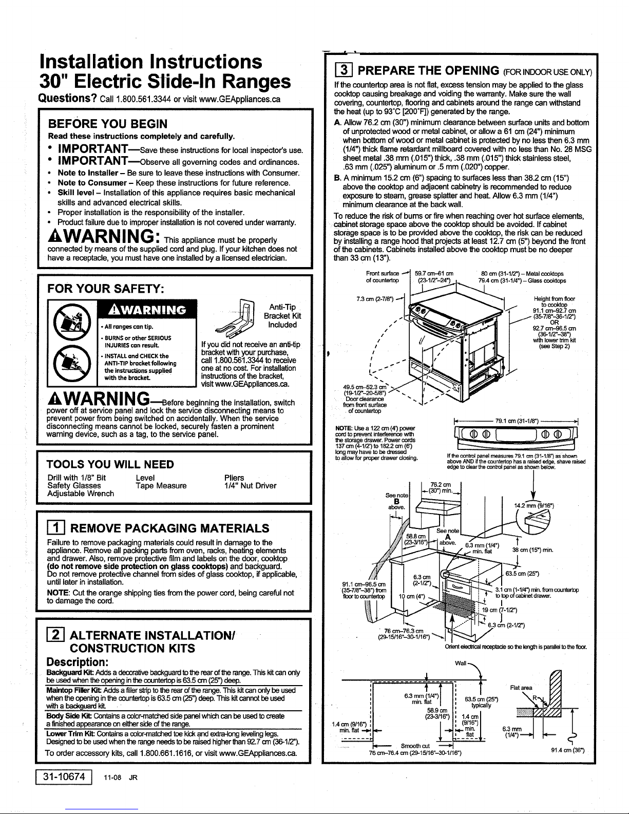
I-_ PREPARE THE OPENING (FOR INDOORUSEONLY)
If the countertoparea isnot flat,excess tension may beapplied to the glass
cooktopcausing breakage and voidingthe warranty.Make surethe wall
covedng,countertop,floodng and cabinetsaroundthe rangecan withstand
the heat (up to 93°C [200°F]) generated bythe range.
A. Allow 76.2 cm (30") minimumclearancebetween surfaceunitsand bottom
of unprotectedwood or metal cabinet, orallow a 61 cm (24") minimum
when bottomofwood or metal cabinet isprotectedby no lessthen 6.3 mm
(1/4")thick flame retardantmillboardcovered withno lessthan No. 28 MSG
sheet metal .38 mm (.015")thick, .38 mm (.015") thick stainlesssteel,
.63mm (.025")aluminum or .5mm (.020")copper.
B. A minimum15.2 cm (6")spacingto surfaceslessthan 38.2 cm (15")
abovethe ccoktop and adjacentcabinetryis recommended to reduce
exposureto steam, grease splatterand heat. Allow 6.3 mm (1/4")
minimumclearanceat the backwall.
To reducethe dskof bums or firewhen reachingover hotsurfaceelements,
cabinet storage spaceabove the cooktopshouldbe avoided. If cabinet
storagespace isto be providedabove the cooktop,the dsk can be reduced
by installinga range hoodthat projectsat least12.7 cm (5")beyond the front
of the cabinets. Cabinets installedabove the cooktop must be no deeper
than33 cm (13").
Front surface -_ 59.7 cm--61 cm 80 cm (31-1/2") - Metal cooktops
ofcountertop , __
7.3 cm (2-7/8") --_
/
I _ _ 1/ tocool(top
' 91.1 cm-92.7 orn
I "]_,e_,.= _'"_ 91.1 cm-92.7 orn
,I_,,L _ _ I j- (35-7/8"-36-1/2")
.. -T-,,_-___.Z,,-_p.j_-__ oR
, I__.,.;"11 _ 27_986o
, I ,"_.__'_._---_1_t _'_ M / (36-1/2"-38")
' I // _.'_"_'l _ / Ihlowertnm
711// " 92.7 cm-96.5Cmwithlower trim kit
79.4 cm (31-1/4") - Glass cooktops
,,' .l ," I. 1 ]IL/ (_step2)
,.. -
49.5 cm-52.3 orn_
49.5,_=-_2.3_.><_I;_">.-_1
Door clearance
fromfront surface
. of countertop
I" 79.1cm(31-1/8") ,1
CON to prevent inten_.mnce _h
the Storage drawer. Powercords
137 cm (4-1/2') to 182.2 orn (6')
longmay have to be dressed
to allow for proper drawer dosing. If the conb'ol panel measures 79.1 cm (31-1/8") as shown
_e°otell-(_°")_°--t *
above AND if the countertop has a raised edge, shave raised
edge to clear the control panel as shown below.
76.2 c[n /
Ill REMOVE PACKAGING MATERIALS
Failure to remove packaging materials couldresultin damage to the
appliance. Remove allpackingpartsfrom oven, racks,heating elements
and drawer. Also, remove protectivefilmand labels on the door, cooktop
(do not remove side protection on glass cooktops) and backguard.
Do not removeprotectivechannelfrom sidesof glasscooktop, ifapplicable,
untillater in installation.
NOTE: Cut the orangeshippingties from the powercord, being careful not
to damage the cord.
ALTERNATE INSTALLATION/
CONSTRUCTION KITS
Description:
Backguard_ Addsa decor-aWebackguardtotherearoftherange.Thiskitcanonly
beusedwhentheopeninginthecountertopis63.5cm (25")deep,
MaintopRllerlot: Addsa fillershiptothe rearofthe range.Thiskitcanonly beused
whenthe openinginthe countertopis63.5cm (25")deep.This kitcannotbe used
witha backguardt_.
BodySide W.,'t:Coffins acolor-matd"_lsidepanelwhichcanbeusedtocreate
: a finishedappearanceoneithersideofthe range.
LowerTrimKit:Containsa coler-m_ toekicka.ndextra-longlevelinglegs.
Designedtobe usedwhen therangeneedstobe raisedhigherthan92.7crn(36-1/2").
To order accessory kits, call 1.800.661.1616, or visit www.GEAppliances.ca.
31-10674
] 11-08 JR
J
• !
1.4_(_16_
(29-15/16"_o-1/1_')'-._1]_
6.3mm(1/4")TI
min. flat / I 63.5 cm (25")
O_ e_ed_cal recoptade so the leng_ is parallel to the flonr,
f
l
(_zg_____ 1.4=1
76 crn-76.4 cm (29-15/16"-30-1/16"
Smooth cut ._
(9/16")I
08. =(2s-)
3.1=
Rat area
6,3 mm
91.4 crn (36")

I-_PREPARE THE RANGE
STORAGE DRAWER REMOVAL
A. Pulldrawer out until it stops.
B. Liftfront of drawer untilthe stops clear the guide.
C. Pull forward and remove the drawer.
Rail
Protective channel
DOOR REMOVAL (optional)
Door removal isnot a requirementfor installation
ofthe productbut is anadded convenience.
To remove the door:.
A. Open the oven dooras faras it willgo.
B.Push both hinge locks down towardthe door
frameto the unlockedposition.Thismay require
a fiat-bladesorewdriver.DO NOT UFT THE
DOOR BYTHE HANDLE!
C. Placehandson bothsidesofthe door,and close
theoven doortothe removalposition.(Approximately
2.5cm--5cm [1--2'1from theclosedposition.)
D. Liftdoorup andoutuntilthehingearmsdear theslots.
NOTE: The oven door isvery heavy. Be sure you havea firmgripbefore
liftingthe oven door off the hinges. Use caution oncethe dooris removed.
Do notlaythe dooron itshandle.This couldcausedentsorscratches.
I
Hinge
Hinge clears slot
Hinge
unlocked
- position
_-I ANTI-TIP DEVICE INSTALLATION
range,the rangemustbesecured
(_ To reducetheriskoftippingthe
thatthelevelingleg is engagedin thebracket.On modelswithouta storagedrawer
or kickpanel, carefullytipthe rangeforward.Thebracket shouldstop therangewithin
10cm (4"). Ifitdoes not,the bracket mustbe reinstalled.Ifthe rangeis pulledfrom
thewallfor any reason,alwaysrepeatthis procedureto vedfytherange is properly
securedbythe anti-tipbrackeLNevercompletelyremovethelevelinglagsor the
rangewill not besecured to the anti-tipdeviceproperly.
• All renges con tip.
• BURNS or other SERIOUS
INJURIEScon result,
• INSTALLond CHECKthe
ANTI-TIP bracket following
the instructions supplied
with the bracket.
by a properlyinstalledanti-_pbracket.
See installationinstruclionsshipped
withthebracketforcompletedetails
To checkifthebracketisinstalled
beforeattemptingtoinstall.
andengagedproperly,remove
thestoragedrawerorkickpanel
andlook underneaththe rangeto see
I-_ SLIDE RANGE INTO OPENING
A. Positionthe range in frontof the cabinet opening. Make
surethatthe glass thatoverhangs the countertopdears _,___--._
the countertop. Ifnecessary, raisethe unit by lowering
the leveling legs.
B,
Push while lifting the range into the opening, untilthe range is within
5 cm (2") of engaging the anti-tip bracket. Remove the protective trim
from the side of glass (If provided). - _ Countertop
C.
Usingthe adjustable pliers or wrench, carefully /__
screw in the beck levelingleg untilthe glass
overhang comes to reston the countertop.
Then carefully screw in the fronttwo leveling
legs untilthe glass overhangtouches
the countertop.
D.
Carefullypushthe rangeintothe opening
untilthe countertop fully engagesthe
contToIpanel.The beck glassoverhang
shouldcoverthe cutoutopening.Plug
the rangecord intothe receptade. Locate
the cordin the back of the rangein a
manner that it will not touch or be moved
by the drawer.
Make sureedge of countertop fitsflush
againstthe end of FrontControlPanel
Posi_onrange/3orclsothat'd-_reisno
interferencewiththestoragedrawer
%
-_.,:
REPLACING THE OVEN DOOR
NOTE:The oven doorisheavy. You may need help lifting
the door highenoughto slide it intothe hingeslots. Do not
liftthedoor by the handle.
A. Liftthe oven door by plating one hand on each side.
The door is heavy,so you may need help. Do notlift
thedoor by the handle.
B.With the door at the same angle as the removal position
(approximately 2.5cm-5 crn [1"-2"] from the closed position), seat
the notch of the hinge arm into the bottom edge of the hinge slot.
The notch of the hinge arm must be f_lly seated into the bottom of the slot.
C• Fully open the door. If the door will not fully open, the indentation
isnot seated correctly inthe bottomedge of the slot.
D. Push the hinge
locksup against Hingeinlocked
the frontframe
of the oven cavity, Notchof hinge
to the locked securelyfitted
position, of hingeslot
E. Closethe oven door.
intobottom
Bottomedgeof slot
REPLACE THE STORAGE DRAWER
A• Place the drawer rail on the guides. Push
the drawer in until it stops.
B, Liftfront of the drawer and push in until
the stops clear the guides.
C. Lower the front of the drawer and push
in until it closes.
FINAL INSTALLATION CHECKLIST
• Checkto makesure the circuitbreakerisclosed(RESET)or the circuitfuses
are replaced.
• Be surepower isinserviceto the building.
• Checkthatall packingmaterialsand taps have beenremoved.Thiswill include
tape onmetalpanelundercontrol knobs(Ifapplicable),adhesivetape, wire ties,
cardboard andprotectiveplastic.Failureto removethese materialscouldresult
indamageto theapplianceoncethe appliancehasbeentumedon and surfaces
haveheated.
• Checkthat thedoorand drawerare paralleltoeachotherand that bothoperate
smoothly.Ifthey do not,see the Owner'sManualfor properreplacement.
• Checkto make surethat the rear levelinglegis fully insertedintothe anti-tip
bracketandthat the bracketissecurelyinstalled.
OPERATION CHECKLIST
• Turn onone ofthe surfaceunitstoobservethatthe elementglowswithin
60 seconds.Turnthe unitoffwhen glowisdetected.Iftheglow isnotdetected
withinthetime limit,rechecktherange wiringconnections. Ifchangeisrequired;
retestagain.If nochangeis required,have buildingwiring checkedforproper
connectionsandvoltage.
• Checkthat the ovenconb'oloperatesproperly.If the ovencontrol doesnot
operateproperly,recheckthewiring connections.
• Be sureall rangecontrolsare inthe OFF positionbeforeleaving the range.
I-_ MODEL AND SERIAL NUMBER LOCATIONS
The ratingplate is locatedon the oven frame or on the side ofthe drawer framei
Ratingplate Ratingplate
 Loading...