

Page 1

GE Fanuc Automation
CIMPLICITY® Display Station
Touch Display:
IC752CTD400/450
Programmable Control Products
GFK-1425B March 1998
Page 2

Warnings, Cautions, and Notes
as Used in this Publication
Warning notices are used in this publication to emphasize that hazardous voltages,
currents, temperatures, or other conditions that could cause personal injury exist in this
equipment or may be associated with its use.
In situations where inattention could cause either personal injury or damage to equipment,
a Warning notice is used.
Caution notices are used where equipment might be damaged if care is not taken.
Notes merely call attention to information that is especially significant to understanding and
operating the equipment.
GFL-002
Warning
Caution
Note
This document is based on information available at the time of its publication. While efforts
have been made to be accurate, the information contained herein does not purport to cover all
details or variations in hardware or software, nor to provide for every possible contingency in
connection with installation, operation, or maintenance. Features may be described herein which
are not present in all hardware and software systems. GE Fanuc Automation assumes no
obligation of notice to holders of this document with respect to changes subsequently made.
GE Fanuc Automation makes no representation or warranty, expressed, implied, or statutory
with respect to, and assumes no responsibility for the accuracy, completeness, sufficiency, or
usefulness of the information contained herein. No warranties of merchantability or fitness for
purpose shall apply.
The following are trademarks of GE Fanuc Automation North America, Inc.
Alarm Master GEnet PowerMotion Series One
CIMPLICITY Genius ProLoop Series Six
CIMPLICITY PowerTRAC Genius PowerTRAC PROMACRO Series Three
CIMPLICITY 90–ADS Helpmate Series Five VuMaster
CIMSTAR Logicmaster Series 90 Workmaster
Field Control Modelmaster
©Copyright 1997—1998 GE Fanuc Automation North America, Inc.
All Rights Reserved.
Page 3

Content of This Manual
This manual describes the features and operation of the following CIMPLICITY Display Station
Touch Display products:
Related Publications
Preface
Catalog Number
IC752CTD400
IC752CTD450
GFK-1189
GFK-1180
GFK-1181
GFK-1396
GFK-1491
At GE Fanuc Automation, we strive to produce quality technical documentation. After you have
used this manual, please take a few moments to complete and return the Reader's Comment Card
located on the next page.
CIMPLICITY
Product Information
CIMPLICITY
Windows
Manual
CIMPLICITY
Windows
Communications Manual
CIMPLICITY
Operation Manual
Important Product Information
®
HMI for Windows NT™ and Windows® 95 Important
®
HMI for Windows NT™/CIMPLICITY HMI for
®
95/CIMPLICITY Server for Windows NT™ Base System User
®
HMI for Windows NT™/CIMPLICITY HMI for
®
95/CIMPLICITY Server for Windows NT™ Device
®
HMI for Windows NT and Windows 95 CimEdit
GFK-1425B iii
Page 4

Contents
Product Features.....................................................................................................2
Display and Touch Screen...................................................................................................3
Floppy Disk Drive Unit ....................................................................................................... 3
Hardware Installation............................................................................................4
Mounting Guidelines ........................................................................................................... 4
Mounting Procedure ............................................................................................................ 6
Installing ISA-Compatible Cards.........................................................................................7
I/O Address and IRQ Allocation................................................................................... 8
Reserved I/O Address....................................................................................................8
Touch Screen Port Address...........................................................................................8
Installing the Floppy Disk Drive........................................................................................ 10
Changing the Air Filter...................................................................................................... 11
To change the air filter element: ................................................................................. 11
Connection ............................................................................................................12
AC Power Input ................................................................................................................. 13
Keyboard............................................................................................................................ 13
Serial C o mmunic a ti o n C a b l es.............................................................................................14
Printer Port LPT1 (Parallel Po r t)........................................................................................ 15
Floppy Disk Drive I nterface................................................................................................15
Initial Startup .......................................................................................................16
Powering Up the Touch Display Unit................................................................................ 16
Setting Up Windows 95 Systems (IC752CTD400)........................................................... 16
Installing Network Driver on Microsoft Windows 95 Systems (IC752CTD400)............. 17
Configuring the Touch Display to Run on a Microsoft Network...................................... 18
Setting up Windows NT Systems (IC752CTD450)........................................................... 19
Installing Network Driver on Microsoft Windows NT Systems (IC752CTD450)............ 20
Login Recommendation..................................................................................................... 21
Registering Your CIMPLICITY Software......................................................................... 21
Installing Application Software......................................................................................... 22
External CD-ROM Drive ............................................................................................ 22
Touch Screen Driver for Windows ............................................................................. 22
Shutting Down the Computer .............................................................................23
System Operation ................................................................................................. 23
External Mouse..................................................................................................................23
CIMPLICITY Software ..................................................................................................... 23
Communications................................................................................................................ 23
BIOS Settings........................................................................................................24
Interrupt Requests and I/O Assignments........................................................... 25
Diagnostics and Troubleshooting........................................................................ 26
Self-Test Diagnostics......................................................................................................... 26
System Test and Initialization..................................................................................... 26
GFK-1425B v
Page 5

Contents
System Configuration Verification ............................................................................. 26
Troubleshooting.................................................................................................................27
Powerup....................................................................................................................... 27
Display.........................................................................................................................28
Memory....................................................................................................................... 28
Touch Screen...............................................................................................................29
External PS/2 Mouse................................................................................................... 29
Keyboard..................................................................................................................... 29
Communications.......................................................................................................... 30
PLC/CPU Connection .................................................................................................30
MODBUS RTU Communications...............................................................................31
Network Communications...........................................................................................31
Printing........................................................................................................................32
Corrective Actions............................................................................................................. 33
Auto Logon Error Message......................................................................................... 33
Calibrating the Touch Screen...................................................................................... 33
CMOS Checksum Error .............................................................................................. 34
Frequently Asked Questions.............................................................................................. 35
Hardware FAQs........................................................................................................... 35
Software FAQs............................................................................................................ 36
Specifications ........................................................................................................37
vi CIMPLICITY® Display Station Touch Display: IC752CTD400/450–March 1998 GFK-1425B
Page 6

Contents
Figure 1. Touch Display Unit Dimensions...................................................................................................... 5
Figure 2. Panel Cutout Dimensions................................................................................................................. 6
Figure 3. Mounting the Touch Display Unit................................................................................................... 6
Figure 4. Card Clamp ...................................................................................................................................... 7
Figure 5. Jumper Locations.............................................................................................................................9
Figure 6. Floppy Disk Drive Mounting......................................................................................................... 10
Figure 7. Filter Element Location ................................................................................................................. 11
Figure 8. Touch Display Connectors............................................................................................................. 12
GFK-1425B Contents vii
Page 7

Contents
Table 1. Touch Display Features..................................................................................................................... 2
Table 2. Touch Screen (Custom COM) I/O address ....................................................................................... 9
Table 3. Touch Screen (Custom COM) IRQ................................................................................................... 9
Table 4. Connector Listing............................................................................................................................ 12
Table 5. IRQ Table......................................................................................................................................... 25
Table 6. I/O Port Range Table....................................................................................................................... 25
viii CIMPLICITY® Display Station Touch Display: IC752CTD400/450–March 1998 GFK-1425B
Page 8
CIMPLICITY® D
ISPLAY STATION
GFK-1425B Touch Display Products
March 1998
IC752CTD400, IC752CTD450
Welcome to GE Fanuc’s CIMPLICITY Display Station products. These products provide an
integrated hardware and software platform for running CIMPLICITY HMI applications. The Touch
Display incorporates CIMPLICITY HMI software for Windows and either Microsoft Windows®
95 or Microsoft Windows NT® software (depending on model). The 10.4” active matrix, thin film
transistor (TFT) color displays provide a large viewing area with crisp color and contrast.
The Touch Display incorporates CIMPLICITY HMI software for Windows, and either Microsoft
Windows® 95 or Microsoft Windows NT® software (depending on model). All Display Stations
come preloaded with the full point count version of CIMPLICITY HMI software.
The Touch Display members of the Display Station family feature a fully self contained Pentium
computer with a built-in 640 x 480 pixel flat screen display and touch-screen surround, housed in an
industrial enclosure, and weighing less than 11kg (25 lbs). The 3.5 inch disk drive adds 1kg (2.2lbs)
to the weight.
The complete unit is housed within a compact, rugged metal enclosure. The unit is supplied
completely assembled and requires only mounting and connecting. Only one panel cut-out is
required to mount the unit. The use of special clips that secure the unit to the panel eliminates the
need for mounting holes.
GFK-1425B 1
Page 9

Product Features
When you purchase a CIMPLICITY Touch Display system, you receive:
•
CIMPLICITY Display Station industrial computer with CIMPLICITY HMI and operating
system software installed.
•
Power cord
•
Floppy disk drive (3.5-inch)
•
Installation hardware
•
CIMPLICITY Display Station Data Sheet which describes specifics of the hardware and
software for your particular system
•
CIMPLICITY Display Station system documentation
•
CIMPLICITY software licenses and license agreements
•
Ethernet driver floppy disk and manual
•
Touch screen driver floppy disk and manual
•
Microsoft Windows documentation, software distribution, Certificate of Authenticity and
license agreement
•
CIMPLICITY software
•
Ethernet driver floppy disk and manual
•
Touch screen driver floppy disk
Touch Display features are summarized in Table 1.
Table 1. Touch Display Features
Operating system
IC752CTD400
IC752CTD450
CIMPLICITY HMI
software
CPU
Hard disk
Floppy disk drive
RAM
Display
Parallel ports
Serial ports
Windows 95
Windows NT
Development and Runtime software
Pentium, 133 MHz
1.2 GB
3.5 inch, 1.44 Mbyte
32 MB
Color TFT (thin film transistor) active
matrix LCD with touch screen surround
one
Two RS-232
2 CIMPLICITY® Display Station Touch Display: IC752CTD400/450 – March 1998 GFK-1425B
Page 10

Display and Touch Screen
The Touch Display features a color liquid crystal display (LCD) with a touch screen surround. The
touch-screen surround, which is an integral part of the front panel on all Touch Display Flat Screen
models, makes operation of a configured system more intuitive by allowing the operator to interface
with the system by simply touching the screen.
The performance of the Touch Display unit is not affected by bright sunlight. The system can also
differentiate between a true touch operation and a beam failure, allowing the system to continue
operation under adverse conditions.
Floppy Disk Drive Unit
A floppy disk drive (IC752FPY000), interface cable and connector are included with the Touch
Display unit. The disk drive unit is housed in a metal case that can be attached to the rear panel of
the Touch Display enclosure.
Using the disk drive that is provided with the Touch Display unit will ensure
compatibility. The use of other types of drives and controllers, which may not be
compatible with the Touch Display, is not recommended.
Note
GFK-1425B Touch Display Products: IC752CTD400/450 3
Page 11

Hardware Installation
This section describes procedures for mounting the Touch Display unit, and installing ISAcompatible cards and the floppy disk drive unit.
A single cut-out is required in the mounting panel. No extra holes are required. Instead, ten springloaded retaining clips are supplied to secure the unit from behind the panel.
The Touch Display unit with processor card weighs 11kg (25lbs) approx. The
3.5-inch disk drive adds 1kg (2.2lbs) to the weight when installed.
Mounting Guidelines
When selecting a location for the Touch Display unit, make sure that there will be enough space for
access to the connectors, located on the right side of the unit. For unit dimensions, refer to Figure 1.
The mounting location for the Touch Display unit should meet the following requirements:
•
The panel into which the unit is mounted should provide protection from dust, dirt and water in
an industrial environment.
•
The panel should be capable of supporting the weight of the Touch Display unit without
distortion.
Note
•
Maximum panel thickness is 10mm (0.39 inch).
•
Allowance should be made for air flow. A fan draws in air through a filter mounted on the side
of the unit. Warm air is expelled through slots in the opposite side panel (refer to Figure 1).
Note
All ten mounting clips must be installed to achieve a good seal between the
Touch Display unit and the mounting panel.
4 CIMPLICITY® Display Station Touch Display: IC752CTD400/450 – March 1998 GFK-1425B
Page 12
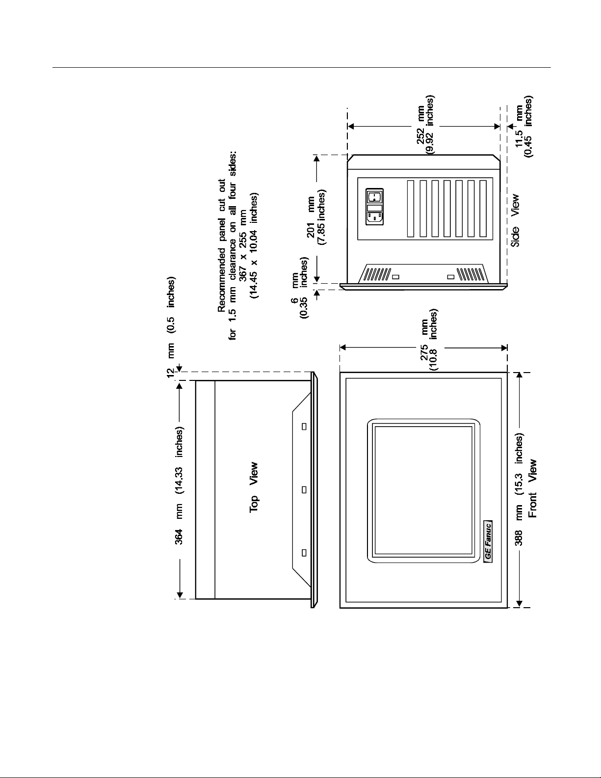
Figure 1. Touch Display Unit Dimensions
GFK-1425B Touch Display Products: IC752CTD400/450 5
Page 13
Mounting Procedure
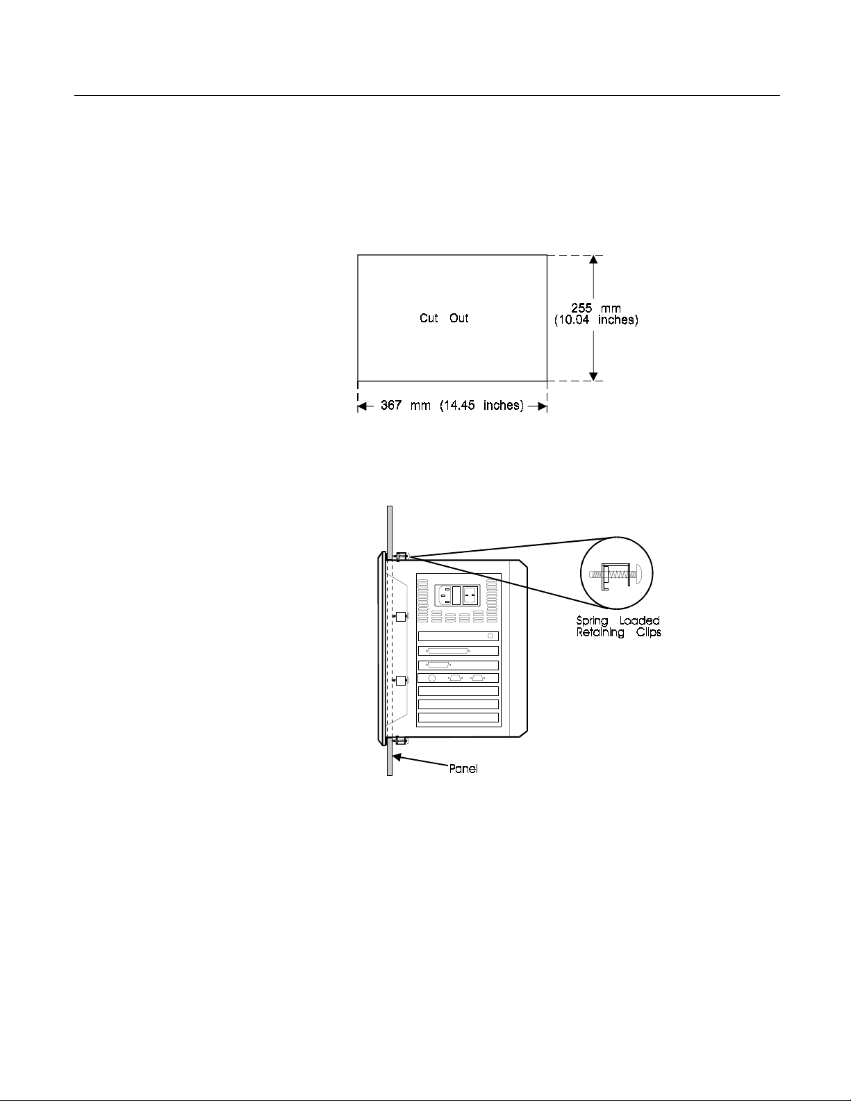
1.Cut out the panel to the dimensions shown. The cut-out dimensions of 367 x 255mm
(14.45 x 10.04 inches) allow a 1.5mm (0.06 inch) clearance on each edge of the Touch Display
unit.
Figure 2. Panel Cutout Dimensions
2
Position the Touch Display unit in the cut-out and fit the ten spring-loaded retaining clips into
.
the slots.
All ten clips must be installed to achieve a good seal
.
Figure 3. Mounting the Touch Display Unit
3
Screw in the tightening screw on each clip so that the nut compresses the spring. To ensure a
.
good seal between the Touch Display unit and the panel, tighten the clips evenly (tighten each
of the ten clips in turn, a little at a time).
Stop tightening the clips when the springs are fully compressed — at this point the Touch
4
.
Display unit is locked in place.
6 CIMPLICITY® Display Station Touch Display: IC752CTD400/450 – March 1998 GFK-1425B
Page 14
Installing ISA-Compatible Cards
The Touch Display rear panel must be removed in order to gain access to the ISA bus cards. There
are six screws securing the rear panel. When these are removed, the rear panel can be lifted away
from the main unit.
Switch off the unit and disconnect the main power input before removing the
rear panel.
Blanking Plates
Blanking plates are installed on each unused card position. Remove blanking plates as necessary to
install new cards. Empty slots must always have a blanking plate installed, otherwise the air flow
through the unit will be affected.
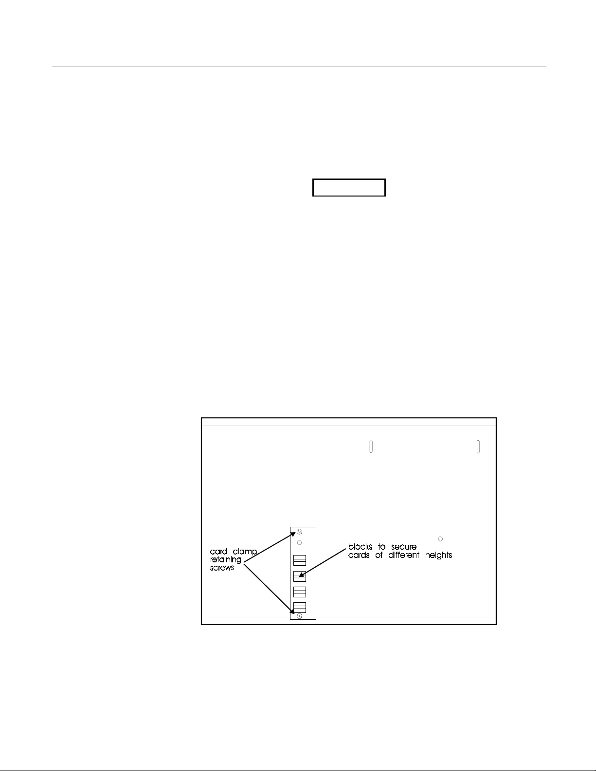
Card Clamp
A card clamp bracket, which can accommodate the two standard heights of ISA bus cards, is fixed
inside the rear panel. The card clamp bracket has nylon card-securing blocks fitted above each
vacant card position. When installing a full height card in one of these positions, remove the long
block from the appropriate position on the bracket and replace with a short block.
Full height cards — 114mm (4.5 inches) approx. — are secured by short nylon blocks
Low height cards — 100mm (3.9 inches) approx. — are secured by long nylon blocks
Warning
Figure 4. Card Clamp
GFK-1425B Touch Display Products: IC752CTD400/450 7
Page 15

I/O Address and IRQ Allocation
For most applications an IRQ cannot be shared by more than one resource.
If more than one resource is set to the same interrupt, the application may
not respond properly and could cause your machine to lock up.
The I/O address and IRQ number of cards being installed must not conflict with those of cards
already installed. Refer to "Interrupt and I/O Assignments" on page 25 for a list of factory-set IRQs.
We strongly recommend that you use only the interrupts that are marked available and use them as
suggested.
Reserved I/O Address
The Touch Display backplane has an 8-bit I/O mapped register intended for future use. This register
is at either 300 hexadecimal or 360 hexadecimal, and is configured by a jumper (link) which is
labeled LK12 or LK15. Its position is the same in either case, and is shown in Figure 5.
LK12 (LK15) IN 300 hexadecimal (factory default)
LK12 (LK15) OUT 360 hexadecimal
Caution
Any hardware adapters installed should not conflict with the above configured address.
Touch Screen Port Address
The Touch Display touch-screen is internally connected as a custom COM port. The I/O addressing
and IRQ setting for the port are configured by jumpers and are factory set to I/O address 310
hexadecimal, IRQ5. Changes should not be made to this port unless a hardware adapter that
interferes with the factory-set addressing for COM4 is being installed. (Refer to Tables 6 and 7 on
page 25.)
Note
Windows based software has been installed to work with the touch-screen via the
touch screen driver s of tware (T5driver for Windows 95, TNdriver for
Windows NT). Check that the COM port parameters given to the driver match the
hardware link sett ings fo r the CUSTOM COM port.
The locations of the jumpers L K2 to LK14 (LK15) are shown in Fig u re 5.
8 CIMPLICITY® Display Station Touch Display: IC752CTD400/450 – March 1998 GFK-1425B
Page 16

Figure 5. Jumper Locations
Table 2. Touch Screen (Custom COM) I/O address
LK2 LK3 Address
OUT OUT Disabled
IN OUT 2E8 hexadecimal
OUT IN 310 hexadecimal (factory default)
IN IN 3E8
Table 3. Touch Screen (Custom COM) IRQ
One jumper determines the IRQ number, depending on its position:
LK6 IRQ3
LK7 IRQ4
LK8 IRQ5 (factory default)
LK9 IRQ6
LK10 IRQ7
LK11 IRQ9
GFK-1425B Touch Display Products: IC752CTD400/450 9
Page 17

Installing the Floppy Disk Drive
The floppy disk drive is designed for mounting on the rear panel of the Touch Display unit. Two
locating slots in the rear panel accept the two metal brackets on the disk drive housing. A
thumbscrew fastens the drive assembly to the rear panel. A ribbon cable, terminated with a D-type
connector, extends from the disk drive to the floppy disk connector at the side of the unit.
Figure 6. Floppy Disk Drive Mounting
Caution
The Touch Display unit must be powered off before the disk drive connector
is connected or disconnected. Failure to observe this precaution will result in
damage to the equipment.
Install the 3.5 inch disk drive as follows:
Power down the Touch Display unit.
.
1
2
Fit the disk drive brackets into the two locating slots on the Touch Display rear panel (refer to
.
Figure 6).
3
For temporary attachment, tighten the fastening screw finger tight. For permanent attachment,
.
use a screwdriver to tighten the screw.
4
Connect the 37-pin D-type connector to the FLOPPY DISK connector and tighten the two
.
securing screws.
5
Power up the Touch Display unit and check that there are no boot up error messages relating to
.
the floppy disk drive.
6
test the drive, insert a formatted disk and select 3 ½ Floppy (A): in Windows Explorer or
. To
File Manager.
10 CIMPLICITY® Display Station Touch Display: IC752CTD400/450 – March 1998 GFK-1425B
Page 18

Changing the Air Filter
The filter element should be changed every three months, or sooner in dusty environments. If the air
filter is not changed at suitable intervals, or a non-approved filter element is installed, the unit may
overheat.
Filter Type: 6.35mm (0.25 inch) thick polyester/polyurethane open cell foam (45 ppi)
To change the air filter element:
The filter element is held directly behind the filter plate in the side of the Touch Display unit.
Figure 7. Filter Element Location
Caution
Power down the Touch Display unit before removing the air filter plate.
Unscrew the screw in the center of the filter plate sufficiently to allow the plate to be removed.
1
.
The screw is captive in the plate.
When the filter plate has been removed, the filter element can be changed. Replace the filter
2
.
plate after changing the filter element.
GFK-1425B Touch Display Products: IC752CTD400/450 11
Page 19

Connection
All connections are made on the side panel of the Touch Display unit. The connector layout is
shown in Figure 8.
Figure 8. Touch Display Connectors
Table 4. Connector Listing
Card Slot
(from top) Type Function
none 3-prong AC power receptacle Power input
1 25-pin, female, D-type Parallel communications
2 37-pin, female, D-type Floppy disk drive connection
3 15-pin, female high density D-type VGA CRT output
4A 6-pin, mini DIN Keyboard connection
4B 9-pin, male, D-type Serial communications
4C 6-pin mini DIN Mouse connection
4D 9-pin, male, D-type Serial communications
5 Coaxial Ethernet communications
5 RJ45 (10BaseT) Ethernet communications
12 CIMPLICITY® Display Station Touch Display: IC752CTD400/450 – March 1998 GFK-1425B
Page 20

AC Power Input
The power input connector is a standard CEE22 type. A power cable is supplied with the Touch
Display unit.
The power supply is auto-ranging, therefore no configuration is needed to change the unit between
110 volt AC and 240 volt AC operation. Check that the fuse is of the correct rating for the supply
voltage.
The panel mounted power input connector houses a 5 x 20mm fuse in a compartment adjacent to
the input socket. The fuse-holder can be accessed only when the power lead is withdrawn.
Fuse value
Keyboard
No keyboard is supplied with the Touch Display product. A PC AT keyboard is required to
configure the application software. After configuration, the Touch Display can be operated without
a keyboard by using the built-in touch screen.
The keyboard connector is a standard 6-pin DIN type, female connector.
2 amps for 240 volt working
4 amps for 110 volt working.
6
5
4
3
12
GFK-1425B Touch Display Products: IC752CTD400/450 13
Page 21

Serial Communication Cables
COM1 and COM2 Pin Assignments
1 DCD
2Rx
3Tx
4 DTR
5 Gnd
6 DSR
7 RTS
8 CTS
9RI
Serial communication cables for COM1 and COM2 should be correctly terminated.
•
Typically COM1 is used for communications to the PLC and COM2 is used for Host
Communications to another device or for a serial mouse.
•
To ensure that the installation meets the EMC radiation specification, the serial cables must
comply with the following requirements:
The cables must be of the shielded type.
The D-type connector covers must provide EMC shielding (e.g. metallized plastic or
die cast metal covers).
a45558
5
1
9
6
The cables must be terminated with 360 degree termination of the shield, as illustrated
below.
14 CIMPLICITY® Display Station Touch Display: IC752CTD400/450 – March 1998 GFK-1425B
Page 22

Printer Port LPT1 (Parallel Port)
LPT1 Pin Assignments
1 Strobe 10 Acknowledge
2 Data Bit 0 11 Busy
3 Data Bit 1 12 Paper End
4 Data Bit 2 13 Select Out
5 Data Bit 3 14 Auto Feed XT
6 Data Bit 4 15 Error
7 Data Bit 5 16 Initialize Printer
8 Data Bit 6 17 Select In (From Printer)
9 Data Bit 7 18 to 25 Ground
Floppy Disk Drive Interface
The 3.5 inch floppy disk drive interface is factory set to Drive A. Connection is via a 37-pin female
D-type connector mounted on the side of the Touch Display unit.
Disk Drive Interface Pin Assignments
1 to 18 Ground 28 DIR Direction
19 +5 VDC. 29 STEP Step Pulse
20 RWC/RPM RPM Low 30 WD Write Data (to
floppy)
21 No connection 31 WE Write Enable
22 No connection 32 TR0 Track 0
23 IDX Index 33 WRPRT Write Protected
24 MO1 Motor Enable 1 34 RDD Read Data (from
floppy disk)
25 DS0 Drive Select 0 35 HS Head Select
26 DS1 Drive Select 1 36 DCHNG Disk Change
27 MO0 Motor Enable 0 37 Vcc +5 V
GFK-1425B Touch Display Products: IC752CTD400/450 15
Page 23

Initial Startup
When you first power up your system, you will need to attach a standard PS/2-type keyboard to the
external keyboard port on the Display Station. When the system starts up, you will be required to
enter the Product ID from the Windows 95 Certificate of Authenticity and other data to set up your
system.
Also, most configuration activities that you perform on a Touch Display system can be more easily
completed using a keyboard or may require a keyboard.
Powering Up the Touch Display Unit
Do not connect or disconnect external devices, such as a printer or an
external floppy drive, while the unit is powered. Failure to observe this
precaution could result in damage to the equipment.
The power switch is located on the side of the Touch Display unit next to the input power
connector. To power up to unit, set the rocker switch to the | position.
During power up, the processor will run its normal diagnostic checks and indicate the presence of
any errors either with a screen prompt or with warning beeps.
Caution
Setting Up Windows 95 Systems (IC752CTD400)
Before you get started you need a PS/2 Keyboard.
Plug in the floppy disk assembly, keyboard, and power cord.
1
.
Power on the unit. The Windows 95 Setup screen will appear.
2
.
Select your Regional Settings. Touch the Next button.
3
.
Select your Keyboard Layout. Touch the Next button.
4
.
Type your name.
5
.
Press the TAB key and type your company name
6
.
NTER
Press E
7
.
Read the license agreement
8
.
Touch your choice.
9
.
Touch Next.
10
.
Enter the Windows 95 Certificate of Authenticity number found on the front of your Windows
11
.
95 manual. Press E
.
NTER
.
16 CIMPLICITY® Display Station Touch Display: IC752CTD400/450 – March 1998 GFK-1425B
Page 24

12.Touch the Finish button. (Although the network card supports Plug & Play mode, this feature
has been disabled due to hardware conflict of non-Plug & Play devices. Please refer to
“Installing Network Driver on Microsoft Windows 95 Systems”.)
Windows 95 will go through setup.
13
.
When prompted for Date/Time Properties, use your left and right arrow key to switch the time
14
.
zone to your time zone. Press E
If you have a printer connected, click Next and select your printer model type. If not, touch the
15
.
Cancel button. The Welcome to Windows 95 window will appear.
Click Close for the Welcome to Windows 95 window.
16
.
NTER
.
Installing Network Driver on Microsoft Windows 95 Systems (IC752CTD400)
Although the network card supports Plug & Play mode, this feature has been disabled due to
hardware conflict of non-Plug & Play devices. It is recommended that the network card use the
NE2000 compatible driver instead of the Plug & Play driver provided on the Ethernet Card
diskette. To set up your network please follow the steps below.
Click the Start icon, click Settings, and Control Panel.
1
.
In the Control Panel window, double click the Network icon. The Network dialog box will
2
.
appear.
In the Network dialog box, click the Add button. The Select Network Component Type dialog
3
.
box will appear.
Click the Adapter icon. The Select Network Adapters dialog box will appear.
4
.
In the list of Manufacturers, select Novell/Anthem. Press the T
5
.
Adapters list. Choose NE2000 Compatible. Click the OK button or press E
In the Network Configuration dialog box, select the NE2000 Compatible line and then click the
6
.
Properties button.
Click the Resources tab. Change the IRQ to 9. Change the I/O address range to 340 — 35F.
7
.
Click the OK button. (The IRQ setting may change to 9/2.)
Click the OK button in the Network dialog box. The system will copy the necessary files and
8
.
prompt you to restart your computer. To acquire network service, restart the computer by
clicking OK or pressing E
NTER
.
AB
key to go to the Network
NTER
.
GFK-1425B Touch Display Products: IC752CTD400/450 17
Page 25

Configuring the Touch Display to Run on a Microsoft Network
Before setting up your new CIMPLICITY Display Station up for the network, you should consult
with your network administrator. Duplicate TCP/IP addresses and duplicate computer names on the
same network cause network problems. Each computer on a network must have a unique name and
TCP/IP address.
Click the Start icon, then click Settings and Control Panel.
1
.
In the Control Panel window, double click the Network icon. The Network dialog box will
2
.
appear.
In the Network dialog box, click the Add button.
3
.
In the Select Network Component Type dialog box, select the Client option. Click Add.
4
.
Select Microsoft as the manufacturer and Client for Microsoft Networks. Click the OK button.
5
.
After your system has restarted, go into the Control Panel and double click on the Network
6
.
icon.
In the Network dialog box, you will see two tabs in addition to Configuration. Click the
7
.
Identification tab. You will need to type in your Computer name, Workgroup name, and
Computer Description.
Note
Computer names must be less than or equal to ten characters to run CIMPLICITY
software. Each computer on a network must have a unique name.
In Windows 95 systems, for Viewers and HMIs to be able to browse remote
nodes, the local computer name must be entered into the
/WINDOWS.000/HOSTS
To allow sharing,
.
8
Go to the Configuration tab and click the File and Print Sharing button. The File and Print
A
.
Sharing dialog box will appear.
Check the File and Print Sharing options that you want and click OK.
B
.
To add the TCP/IP protocol,
9
.
go to the Configuration tab and click the Add button. The Select Network Component
A
.
dialog box will appear.
Click the Protocol icon and click the Add button. The Select Network Protocol dialog box
B
.
will appear.
In the Manufacturer list, select Microsoft. In the Protocol list, select TCP/IP. Click OK.
C
.
When you have finished setting up the Network, click OK in the Network dialog box. Click
10
.
Yes to reboot your system now.
file.
18 CIMPLICITY® Display Station Touch Display: IC752CTD400/450 – March 1998 GFK-1425B
Page 26

Setting up Windows NT Systems (IC752CTD450)
Before you get started you will need to connect a PS/2 keyboard to the Display Station.
Plug in the floppy, keyboard, and power cord.
1
.
Power on the unit.
2
.
Read license agreement
3
.
TAB to your choice and press E
4
.
Press Enter to start the Windows NT Setup.
5
.
Type your name
6
.
Press the TAB key and type your company name.
7
.
Press Enter
8
.
Enter your Windows NT Authentication number found on your Windows NT manual. You
9
.
will need to use the T
Enter a Computer name. This name should be unique to other computers on the same network.
10
.
NTER
Press E
.
AB
NTER
.
key to get to each number field. If correct, press E
NTER
.
Note
Your system has been set up to enable autologon. Autologon allows the system to
boot into Windows NT without your having to use a keyboard to press C
DEL
.
11
You will be prompted for a password.
.
TL-ALT
Note
The password is case sensitive. You must use lowercase ge for the password.
-
•
To use the autologon feature, type ge for the password. Press the T
NTER
NTER
NTER
.
.
AB
key, and type the password in the
NTER
.
the Confirm Password box. Press E
•
To skip the password, press E
•
To assign a password, type in a password, press the T
Confirm Password box. Press E
NTER
Press E
12
.
Refer to the network setting for your product part number to set up the network.
13
.
After completing the network setup the system will copy files over and finalize its setup.
14
.
At the end you will be ask to reboot the system. Press E
15
.
GFK-1425B Touch Display Products: IC752CTD400/450 19
to continue with Windows NT Setup.
AB
key and type ge in
Page 27

Installing Network Driver on Microsoft Windows NT Systems (IC752CTD450)
1.During the initial setup of Windows NT, the system will display a screen with the following
options already selected:.
“This computer will participate on a network.”
“Wired to a network:”.
NTER
Press E
to accept the default
.
NTER
NTER
NTER
.
.
.
2
Press the TAB key three times to select “Select from list…” option. Press E
.
3
Page down (approximately 29 times) to select “Novell NE2000 Compatible Adapter.” Press
.
NTER
.
E
You should see your selection on the next screen. If okay, press E
4
.
If necessary, consult your network engineer to select the Network protocols and TCP/IP
5
.
address selection. In most cases, you will only need, the TCP/IP protocol, but it does not hurt
to enable all the protocols.
The Novell NE2000 Compatible Network Card Setup dialog box will pop up. Use the TAB key
6
.
and up and down arrow keys to select IRQ2 and I/O Address 340. Press E
The Novell NE2000 Adapter Bus Location dialog box will appear. Press E
7
.
In most cases, you will enter a specific unique IP address and not enable the DHCP option.
8
.
Follow the menus as displayed for finalizing your network setup.
9
.
NTER
20 CIMPLICITY® Display Station Touch Display: IC752CTD400/450 – March 1998 GFK-1425B
Page 28

Login Recommendation
If you enter ge as your Administrator password, your CIMPLICITY Display Station will
automatically log on as Administrator.
Log onto the system as Administrator when you power up the system. Doing so eliminates the
requirement to log on to CIMPLICITY when you run the CIMPLICITY Demo or any other
CIMPLICITY project that includes a user named Administrator. All CIMPLICITY projects are
configured with an Administrator user by default.
Registering Your CIMPLICITY Software
All Display Stations are licensed to run CIMPLICITY software. You will need to register your
CIMPLICITY software by following the steps below. Licenses have been loaded for CIMPLICITY
HMI Base, Trending, TCP/IP Communications, and Series 90 SNP Communications numbers can
be found in the license packs provided. If you purchase additional product options to run on the
Display Station, you will need to contact GE Fanuc to update the system licensing.
Click Start, Programs, CIMPLICITY, HMI, Registration.
1
.
Click Next for new User.
2
.
Read the License Agreement and select Yes if you agree.
3
.
Fill in the User Information.
4
.
Click Next
5
.
Open your CIMPLICITY software box and find your license packs. Open each license pack
6
.
and type the serial numbers in the fields provided.
Call the CIMPLICITY phone number that appears on the screen.
7
.
Faxes and phone calls will be processed between 8 AM and 5 PM Eastern time, Monday through
Friday, except for regularly scheduled holidays. Faxes and calls received after hours, on weekends,
or holidays will be processed as soon as possible on the following business day.
When you phone, please be prepared to provide GE Fanuc with the following information:
•
Your User information
•
CIMPLICITY serial numbers
•
The System Key Code generated during the registration procedure
Note
When it is installed without the authorization code, you can run the software as a
fully functional system in two-hour increments.
GFK-1425B Touch Display Products: IC752CTD400/450 21
Page 29

Installing Application Software
The Windows operating system and CIMPLICITY HMI software is loaded onto the Touch Display
unit at manufacture. If it is necessary to reload software, follow the instructions in the
documentation supplied with the software. The following sections give tips for customizing the
software for the Touch Display platform.
External CD-ROM Drive
A driver, BP32DRV, is factory-installed to allow the Micro Solutions Backpack ™ External CDROM Drive to be used for loading software. To enable this driver on units with Windows NT,
select Devices under Control Panel, select BP32DRV, and change Startup setting to System. Close
the Control Panel, shut down, and connect the drive to the parallel port. Restart the system and open
Windows NT Explorer. The CD-ROM should appear as D:. When finished, the driver can be set to
Disabled again. For units using Windows 95, simply shut down, connect the drive, and restart.
Touch Screen Driver for Windows
Operation of the touch screen surround requires the software driver T5driver for Windows 95 .or
TNdriver for Windows NT.
The integral touch-surround of the Touch Display unit is internally connected to the serial port on
the backplane. Parameters must be given to the software driver to match the hardware settings (refer
to Touch-screen Port Address, page 8). The factory default settings are:
COM Port = CUSTOM
Address = 310 hexadecimal
Interrupt = 5
These parameters are written into the Windows SYSTEM.INI file by the touch screen software
driver setup utility. T5driver or TNdriver will be installed, configured and calibrated at
manufacture.
Note
When the above parameters are entered u sin g TNSetup, a message is given that a
line should be added to AUTOEXEC.BAT, such as :
C:\WINDOWS\TBBIOS 3 310
This message can be ignored.
22 CIMPLICITY® Display Station Touch Display: IC752CTD400/450 – March 1998 GFK-1425B
Page 30

Shutting Down the Computer
To avoid damaging files, always shut down Windows software before
removing power from your Display Station product.
To shut down Windows 95 or Windows NT software, select Shut Down from the Start menu.
System Operation
External Mouse
The touch screen and PS/2 mouse will work simultaneously if the mouse is 100% Microsoft or IBM
PS/2 compatible. Because Windows can load only one mouse driver at a time, it is not possible to
provide simultaneous support for a mouse that requires its own specific Windows driver.
CIMPLICITY Software
For detailed software operating instructions, refer to the following documentation.
GFK-1189
GFK-1180
GFK-1181
GFK-1396
CIMPLICITY
Product Information
CIMPLICITY
Windows
Manual
CIMPLICITY
Windows
Communications Manual
CIMPLICITY
Operation Manual
Caution
®
HMI for Windows NT™ and Windows® 95 Important
®
HMI for Windows NT™/CIMPLICITY HMI for
®
95/CIMPLICITY Server for Windows NT™ Base System User
®
HMI for Windows NT™/CIMPLICITY HMI for
®
95/CIMPLICITY Server for Windows NT™ Device
®
HMI for Windows NT and Windows 95 CimEdit
Communications
®
For information on the hardware setup for device communications, refer to
Windows NT™/CIMPLICITY HMI for Windows
Device Communications Manual
Your CIMPLICITY Touch Display has been configured with networking components that enable
you to establish new networks or connect to existing networks easily. If you intend to use Microsoft
NetBEUI, TCP/IP, or Direct Cable Connection, some minimal setup changes are required before
you can use the system for network applications. In both Windows 95 and Windows NT systems,
these settings are changed using the Network application in the Control Panel program group.
GFK-1425B Touch Display Products: IC752CTD400/450 23
, GFK-1181.
®
95/CIMPLICITY Server for Windows NT™
CIMPLICITY
HMI for
Page 31

BIOS Settings
It is normally not necessary to change the hardware configuration settings in the CMOS memory. If
settings become corrupted, follow the procedures here to reload the factory configuration.
Enter the CMOS Setup mode by pressing the D
up sequence. A screen will appear offering several options for changing settings, restoring default
settings, and other functions. Follow these instructions to restore the factory configuration.
1
.
2
.
3
.
EL
key when prompted during the computer power-
Select the Load BIOS Defaults option. Then, select the Save CMOS settings option. You will
be prompted to exit.
Go into Standard CMOS Setup and make the following selections:
Primary HDD master AUTO, LBA mode
Secondary HDD master
and slave
Primary HDD slave NONE
Drive A 1.44 MB 3.5” drive
Drive B NONE
Halt on Errors All, but keyboard
Exit Standard CMOS Setup.
Go into BIOS Features Setup and make the following selections:
Bootup Floppy Seek No
Boot Search Order A,C
Do not
exit at this time.
NONE
Exit BIOS Features Setup.
Go into Chipset Features Setup. Set parallel port to ECP+EPP. Exit Chipset Features Setup.
4
.
Select Save and Exit Setup. The startup sequence should begin now.
5
.
The system is now configured with factory CMOS settings.
24 CIMPLICITY® Display Station Touch Display: IC752CTD400/450 – March 1998 GFK-1425B
Page 32

Interrupt Requests and I/O Assignments
Caution
Each hardware resource in the system must be assigned a unique interrupt
request (IRQ) number and an I/O address range. If these settings overlap,
the system will not function properly.
Below is a list of the factory-set IRQs and addresses used in the system, and whether they are
available for add-in cards. Problems can be avoided if add-on devices use the IRQs and address
ranges labeled "Available". If necessary, the touch screen and network card settings can be changed
to accommodate new hardware that will only work at the settings used by these devices. The
directions for changing the touch screen settings are provided in this document. Utilities for
changing network card settings are in the C:NWCARD directory.
Table 5. IRQ Table
IRQ2/9 Network Adapter
IRQ3 COM 2
IRQ4 COM 1
IRQ5 Touch Screen Controller
IRQ6 Reserved
IRQ7 Reserved
IRQ8 Reserved
IRQ10 Available
IRQ11 Available
IRQ12 Reserved
IRQ13 Reserved
IRQ14 Reserved
IRQ15 Available
Table 6. I/O Port Range Table
000-1FF Reserved
200-27F Available
280-2FF Reserved
300-31F Touch Screen Controller
320-33F Available
340-377 Network Adapter
378-3DF Reserved
3E0-3EF Available
3F0-3FF Reserved
GFK-1425B Touch Display Products: IC752CTD400/450 25
Page 33

Diagnostics and Troubleshooting
This section consists of “Self-Test Diagnostics,” “Troubleshooting,” and “Corrective Actions.”
“Self-Test Diagnostics,” describes how to respond to errors that could be detected by the automatic
self test that is performed each time the Display Station powers up. “Troubleshooting” contains
tables of symptoms, their possible causes, and recommended corrective actions. “Corrective
Actions” contains detailed procedures that are too lengthy to include in the Troubleshooting tables.
Self-Test Diagnostics
The computer automatically performs self-test diagnostics each time it is powered up. The self-test
consists of a series of checks that verify correct performance of the computer hardware. When the
self-test is being performed, you will see the message XXXX KB OK displayed on the screen,
where XXXX is a number that increases until it matches the amount of usable memory.
System Test and Initialization
These routines test and initialize board hardware. If the routines encounter an error during the tests,
you will see an error message on the screen. There are two kinds of errors: fatal and non-fatal. If a
non-fatal error occurs, the system can usually continue the boot up sequence. Non-fatal error
messages usually appear on the screen with the following instruction:
Write down the message and press the F1 key to continue the bootup sequence.
System Configuration Verification
These routines check the current system configuration against the values stored in the CMOS
memory. If they don’t match, the program will generate an error message. To correct this condition,
you will need to run the BIOS setup program and correct the configuration information in memory.
(Refer to page 24.)
There are three situations in which you might need to change the CMOS settings:
.
You are starting your system for the first time.
1
You have changed the hardware attached to your system.
2
.
The CMOS memory had lost power and the configuration information has been erased. If this
3
.
has happened, call GE Fanuc’s CIMPLICITY hotline.
press <F1> to RESUME
26 CIMPLICITY® Display Station Touch Display: IC752CTD400/450 – March 1998 GFK-1425B
Page 34

Troubleshooting
Powerup
For Windows NT systems only:
The following error message
appears:
The system could not
log you on. Make sure
your User name and
Domain are correct ...
Display Station does not power
up.
Display is blank (PWR indicator is
lighted).
Non-System disk or disk
error
Safe Recovery Error
message displayed.
Memory count during powerup
self-test is incorrect.
CMOS checksum error —
Defaults loaded
CMOS battery failed
message displayed.
A screen appears just after
powerup, or just after reset, which
has the title “CMOS Setup
Utility.”
The Display Station reset even
though the power was not
interrupted.
A:> appears instead of software. A system floppy disk is inserted. Remove disk and cycle power.
Symptom Possible Causes Solution
message displayed.
You did not type ge for the
password during initial setup.
Power not on (PWR indicator not
lighted or display completely
dark).
See “Display” on page 28. See “Display” on page 28.
Disk in floppy disk drive. Remove floppy disk and then
Occurs on initial power up if the
unit is accidentally turned off
without first shutting down the
Windows 95 software.
Optional SIMM is installed
incorrectly or is incompatible with
the Display Station CPU.
CMOS battery failure.
DEL
The
accidentally pressed.
The
pressed twice at the same time.
key has been
TRL-ALT-DEL
C
keys were
Set the logon password to ge. For
instructions, see “Auto Logon
Error Message” on page 33.
Make sure that Display Station is
plugged in. Make sure that power
source is functioning properly.
reboot or power cycle.
The Display Station will power up
normally.
Make sure that the appropriate
memory is installed correctly.
Note:
This battery has a lifetime
of up to 10 years under normal
operating conditions. The battery
is not field replaceable. For more
information, see “CMOS
Checksum Error” on page 33.
Cycle power again. The Display
Station will power up normally.
This should never be done, unless
you are attempting to reset the
Display Station.
GFK-1425B Touch Display Products: IC752CTD400/450 27
Page 35
Display
Memory
Symptom Possible Causes Solution
Characters are dim. Computer screen is in direct light. Change lighting or adjust contrast.
Display is blank (PWR indicator is
lighted).
Screen has overheated. If Display Station is in direct
sunlight, move it and allow it to
cool.
Display Station is set up for
invalid video mode.
Screen saver is active. Touch the touch screen, or a key
Reboot.
Windows NT models: select VGA
Mode
Windows 95 models: press
when “Starting Windows 95”
appears, then select Safe Mode.
If Windows is now displayed, go
into Control Panel, Display
Settings, and change settings to
the correct video driver and mode.
Contact GE Fanuc’s
CIMPLICITY hotline for more
information.
on the keypad.
F8
Symptom Possible Causes Solution
Memory count during powerup
self-test is incorrect.
Out of Memory
displayed or insufficient memory
error occurs during operation.
message is
Optional SIMM is installed
incorrectly or is incompatible with
the Display Station CPU.
System ran out of memory for the
application.
Too many terminate and stay
resident (TSR) programs running.
Make sure that the appropriate
memory is installed correctly.
Check the memory requirements
for the application. (Refer to the
application documentation.)
Install additional memory.
Modify the startup folder to use
only those TSR applications that
are really needed.
28 CIMPLICITY® Display Station Touch Display: IC752CTD400/450 – March 1998 GFK-1425B
Page 36

Touch Screen
Cursor does not respond at all to
touch.
Cursor moves but does not follow
your touch accurately.
Touch screen responds erratically
to touch; cursor might not be
visible.
External PS/2 Mouse
Note
Operating temperature can affect touch screen calibration. If touch screen
operation is slightly off, recalibrate it by running calibration from the Touch
Screen icon in Control Panel.
Symptom Possible Causes Solution
Touch screen disabled. Make sure documented default
touch screen settings are selected.
Touch screen driver accidentally
deleted.
System is busy. Press C
Touch screen not calibrated
properly.
Display Station is connected to a
serial mouse.
Touch screen settings are
incorrect.
Reinstall touch screen driver
TRL-ALT-DELETE
view task list.
Run calibration from ELO Touch
Screen in Control Panel (see page
33).
Disconnect serial mouse, connect
a PS/2 mouse, and reboot.
Refer to page 22 for settings.
once to
Keyboard
Symptom Possible Causes Solution
Cursor does not respond to mouse
movement
Mouse not plugged in. Plug mouse into mouse port on
The type of mouse is not
supported.
System is busy. Press C
Mouse not detected. Restart Display Station product
Symptom Possible Causes Solution
External keyboard locks up The type of keyboard is not
supported.
Keyboard not plugged into
keyboard port on Display Station.
System is busy. Press C
Display Station and reboot.
Use a PS/2 mouse.
TRL-ALT-DELETE
task list.
with external mouse connected.
Use a Key Tronic keyboard. (Most
keyboards will work. However, we
recommend a keyboard
manufactured by Key Tronic.)
Plug keyboard in.
TRL-ALT-DELETE
task list.
to view
to view
GFK-1425B Touch Display Products: IC752CTD400/450 29
Page 37

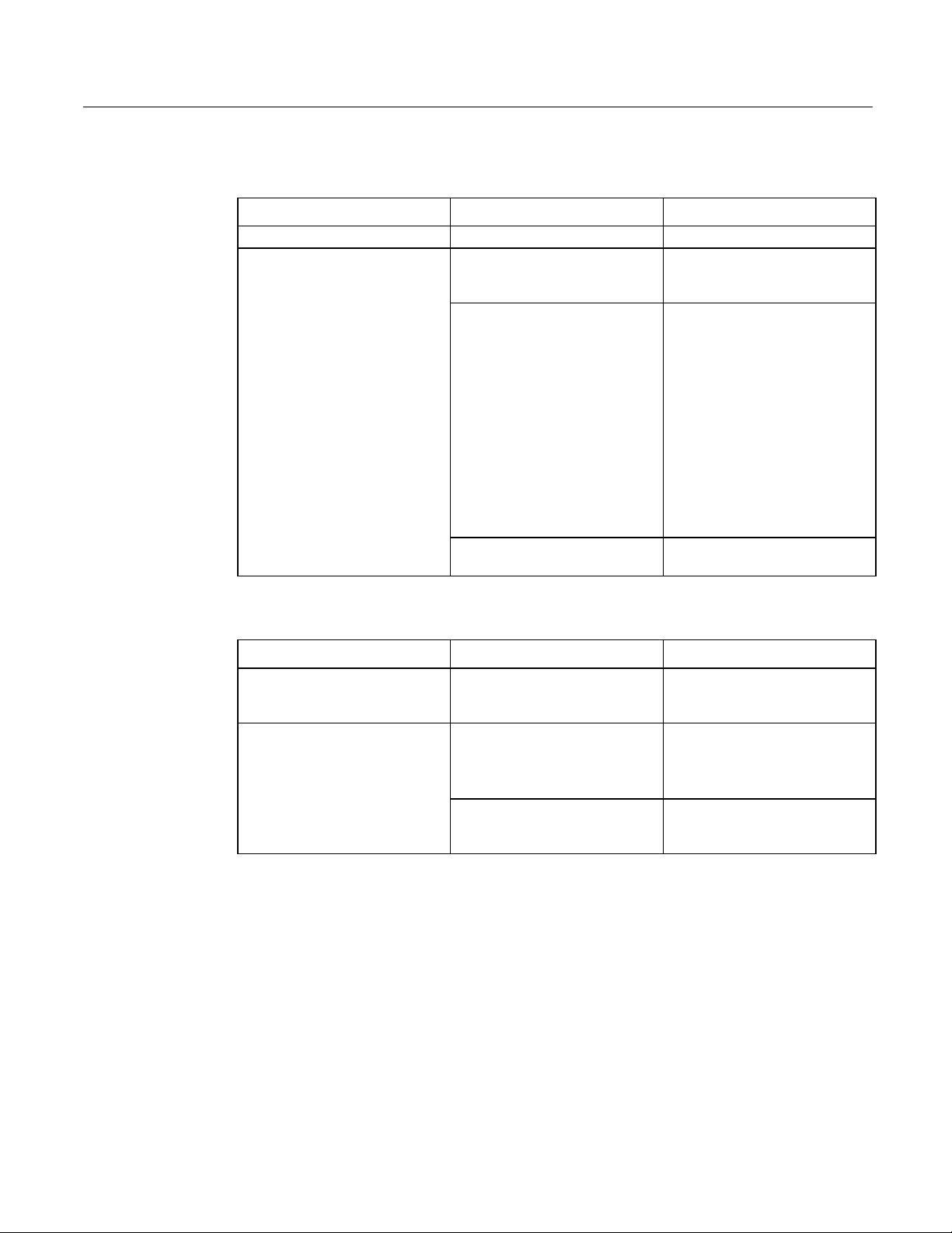
Communications
PLC/CPU Connection
Symptom Possible Causes Solution
CIMPLICITY does not
communicate with a PLC that has
been autoconfigured
(AUTOCONFIG/DEFAULT/I/O
error).
Communications between the host
computer and the controller are
unsuccessful.
The system is attempting to
communicate with a 90-30 PLC
using the SNP driver and a
CIMPLICITY project.
COM port not configured in
system.
Cabling between computer and
controller.
Baud rate and parity configured
incorrectly.
Wrong address. Verify that the slave address is
1. With the PLC powered up and
connected to the Display Station,
establish communication between
the Display Station and PLC via
the 90-30 SNP driver.
2. Using a Hand-Held
Programmer, toggle the Default
I/O (Enable or Disable)
configuration parameter for the
CPU. Communications between
the Display Station and the PLC
will be stopped. (Communications
are stopped when you toggle from
Enable to Disable, or vice versa.)
3. Power cycle the PLC.
Verify that the COM port is
configured in the system.
Verify that the cable between the
computer and the controller is
correctly wired.
Verify that the baud rate and
parity on the computer are
consistent with those on the
controller.
correct.
30 CIMPLICITY® Display Station Touch Display: IC752CTD400/450 – March 1998 GFK-1425B
Page 38

MODBUS RTU Communications
Symptom Possible Causes Solution
Communications between the host
computer and the controller are
unsuccessful.
COM port not configured in
system.
Cabling between computer and
controller.
Baud rate and parity configured
incorrectly.
MODBUS port not configured for
RTU communications.
Wrong address. Verify that the slave address is
Verify that the COM port is
configured in the system.
Verify that the cable between the
computer and the controller is
correctly wired.
Verify that the baud rate and
parity on the computer are
consistent with those on the
controller.
Verify that the controller's
MODBUS port is configured for
RTU communications.
correct.
Network Communications
Symptom Possible Causes Solution
Conflicts on network. IP Address not unique. Change the IP address to a unique
address. (Contact your system
administrator if this or other
settings need to be changed.)
GFK-1425B Touch Display Products: IC752CTD400/450 31
Page 39

Printing
Symptom Possible Causes Solution
Printer will not turn on. Cables not connected properly.
Printer power cord not plugged in.
Printer will not print. Printer is not turned on. Turn on the printer
Printer is not online. Set the printer to online.
The device drivers for your
application are not installed.
Printer that is set up for a network
is not connected to the network.
Printer cable is too long,
unshielded, or defective.
Printer is offline. Paper tray is empty. Fill the paper tray with paper. Set
Printer prints garbled information. Correct printer drivers not
installed.
Cable is not connected properly. Ensure that the printer cable is
Problem specific to printer. Run a printer self-test. Refer to the
Ensure that the cables are properly
connected and that the power cord
is connected to the electrical
outlet.
Install the correct printer drivers
for your application in Windows.
Connect the printer to the
network.
Replace the cable.
printer to online.
Install the correct printer driver.
connected properly to the
computer.
documentation provided with your
printer for instructions. If the selftest fails, the problem is printerspecific. The printing section of
the software documentation and in
Windows online Help may also be
helpful.
32 CIMPLICITY® Display Station Touch Display: IC752CTD400/450 – March 1998 GFK-1425B
Page 40

Corrective Actions
Auto Logon Error Message
All Windows NT CIMPLICITY Display Station products have the auto logon feature enabled with
as the password. This feature eliminates the need for a keyboard to type C
ge
enter a password. If, during initial setup, you do not type ge as your password, you will receive the
following error message each time the system is booted.
Logon Message
The system could not log you on. Make sure your User name and
Domain are correct, then type your password again. Letters in
the password must be typed using the correct case. Make sure
that Caps Lock is not accidentally on.
This message means that auto logon could not occur because the password is something other than
. If you want to enable auto logon and avoid the error message, complete the following
ge
instructions:
Click Start, Programs, Administrative Tools, and User Manager.
1
.
If Administrator is highlighted, click User in the top task bar and select Properties.
2
.
In the Password and Confirm Password fields, type ge. Click OK.
3
.
TRL-ALT-DEL
and
Press ALT-F4 to close the User Window.
4
.
If you wish to log on manually, click OK to the error message and log on normally. To eliminate the
error message for future manual logons, you will need to edit the registry on your Display Station
product. For details on editing the registry, you will need to call the CIMPLICITY hotline.
Calibrating the Touch Screen
During the first time powerup of the Display Station, you might need to calibrate the touch screen.
To do this, connect an external PS/2 mouse or a PC AT keyboard and complete the following steps:
Click the Start button. (If you are using a keyboard, press C
1
.
menu.)
Go to Settings and select Control Panel.
2
.
Select the ELO Touchscreen icon.
3
.
Press Enter to run the calibration. Follow the instructions presented by the calibration program.
4
.
TRL-ESC
to bring up the Start
GFK-1425B Touch Display Products: IC752CTD400/450 33
Page 41

CMOS Checksum Error
If the CMOS battery has failed, the following error messages will be displayed on the screen:
CMOS checksum error - Defaults loaded
CMOS battery failed
If you see the above message, you can still operate the Display Station by pressing the D
and manually setting up the system. (You will need to set up the computer each time the system is
powered up.) For setup parameters, refer to “BIOS Settings.”
ELETE
key
This battery has a lifetime of up to 10 years under normal operating conditions.
field replaceable. The Display Station unit must be returned to GE Fanuc to correct the problem.
The battery is not
34 CIMPLICITY® Display Station Touch Display: IC752CTD400/450 – March 1998 GFK-1425B
Page 42

Frequently Asked Questions
Hardware FAQs
My touch screen isn’t working. What should I do?
Ensure that the Touch Screen settings (in the Control Panel, double click the Touch Screen icon)
are set as described in “Touch Screen Driver for Windows” on page 22.
Where is the right mouse button when using the touch screen?
This feature is not supported on the touch screen.
Can I use an external mouse and the touch screen at the same time?
Yes. A external PS/2 mouse can be used with the touch screen if the system is rebooted after it is
connected. True for these models?
How do I clean the touch screen?
Touch screens can be wiped down with a clean cloth or paper towel dampened with water or glass
cleaner.
How do I upgrade the Touch Display RAM?
All Touch Display products have at least 32MB of RAM installed in the factory. You can order
additional RAM with your initial order or upgrade at a later time. Currently, you can upgrade to
64MB (IC752RAM032) or 128MB (IC752RAM128) of RAM.
My Touch Display unit has a 1.2GB hard drive. How can I get a larger drive?
Hard drives must be installed in the factory to retain the Touch Display warranty. An upgrade to a
2GB drive is available. To upgrade your drive, send the Touch Display product to the factory and
order the upgrade part number (IC752HDD200). Touch Display products can be ordered initially to
include this upgrade.
Can I upgrade the CPU in my Touch Display?
All Touch Display products contain at least Pentium 133 CPUs. Upgrades to Pentium 200 are
available. All CPU upgrades must be done in the factory to retain the warranty.
GFK-1425B Touch Display Products: IC752CTD400/450 35
Page 43

Software FAQs
What HMI software comes preloaded on the Touch Display product?
Beginning in mid-February 1997, all units come preloaded with the full point count version of HMI
software. You can get either Windows ’95 or Windows NT operating system with the
development/runtime packages. All Touch Display products come with server packages but can be
operated as viewers.
Will Display Station products with limited point counts be offered?
There are no plans for this at this time.
I am using the touch screen and would like to know if I can log on to an NT System without a
keyboard. Can I do this?
All systems have autologon enable for Administrator with ge as the password. For details, see page
21.
To disable the screen logon message, refer to the CIMPLICITY Web page at
http://www.cimplicityhmi.com/appnote/logon.htm. The application note provided at this Web site
describes how to create a default logon for the operating system that also acts as a logon for
CIMPLICITY so that you only need to turn on the machine to have CIMPLICITY come up and be
ready for use.
I heard that there is now a longer period that the software will run without authorization. What are
the details?
You should go ahead and register your CIMPLICITY software. The period of four days starts when
CIMPLICITY is first loaded. Your system will default to the two-hour limit because the four days
will have expired.
36 CIMPLICITY® Display Station Touch Display: IC752CTD400/450 – March 1998 GFK-1425B
Page 44

Specifications
Features
Microprocessor Pentium 133 MHz
Math Coprocessor built in
User memory 32 Mbyte
Operating System Microsoft Windows 95 or Microsoft Windows NT
Hard Disk 1.2 Gbyte
ISA bus card slots Six total. Two full length slots available for additional cards.
Total current available for sharing by up to two user cards +5 VDC, 1.2 A approx.
+12 VDC, 0.1 A approx.
-12 VDC, 0.1 A approx.
Display
Type 640 x 480 pixel
Color TFT (thin film transistor) active matrix LCD
Area 211 x 159mm (8.31 x 6.26 inches)
Power Requirements
AC Input 85 to 250 VAC, 110 W, Auto-ranging, 47 to 63 Hz
Fuse Rating 4 A (90 to 132 VAC) 2 A (180 to 250 VAC.)
Inrush Rating 17 A at 110 VAC, 34 A at 220 VAC
Ports
Parallel Ports One LPT1
Serial Ports Two external RS232 ports: COM1 and COM2
Also CUSTOM COM (wired internally to touch-screen)
Keyboard Port PS/2
Floppy Disk Interface 3.5 inch, 1.44 Mbyte via 37-pin D-type connector
Configured as drive A:
Environmental
Operating Temperature Ambient working temperature range 0 to 40 oC
Relative Humidity 5 to 85% non-condensing
Drop Test 1 meter drop onto any face within packaging
GFK-1425B Touch Display Products: IC752CTD400/450 37
Page 45

Index
A
AC Input, 13
Air filter, 11
Audible warning, 16
Auto Logon error message, 33
Autologon, 19
B
Backplane
reserved I/O address, 8
BIOS settings, 24
C
Calibrating the touch screen, 33
Card Clamp, 7
Catalog numbers
floppy disk drive
IC752FPY000, 3
Touch Display
IC752CTD400, 2
IC752CTD450, 2
Catalog numbers, upgrades
IC752HDD200, 35
IC752RAM032, 35
IC752RAM128, 35
CIMPLICITY software
operation, 23
CMOS battery, 27, 34
CMOS checksum error, 34
CMOS settings, 26
COM Ports connector, 14
Communications, 23
troubleshooting, 30
Configuring the network, 18
Connection, 12
Custom COM port addressing, 8
E
Environmental Specification, 37
Error messages
AUTOCONFIG/DEFAULT I/O, 30, 31
CMOS checksum error, 27, 34
CMOS Setup Utility, 27
Disk Error, 27
Insufficient memory, 28
Logon, 27
non-fatal, 26
Non-system disk, 27
Out of Memory, 28
Safe Recovery, 27
External mouse, 23
F
Floppy disk drive
installing, 10
Fuse rating, 37
H
Hardware installation, 4
I
Initial startup, 16
Installing application software, 22
Installing ISA-compatible cards, 7
Installing Network Driver
Windows 95, 17
Windows NT, 20
Interrupt requests and I/O assignments, 25
K
Keyboard, 13
troubleshooting, 29
D
Diagnostics
bootup sequence, 26
Self-test, 26
system configuration verification, 26
system test and initialization, 26
Diagnostics and troubleshooting, 26
Display
troubleshooting, 28
Display Area, 37
GFK-1425B Index-1
Login recommendation, 21
Memory
MODBUS RTU communications
Mounting Guidelines, 4
L
M
troubleshooting, 28
troubleshooting, 31
Page 46

Index
N
Network communications
troubleshooting, 31
P
PLC/CPU connection
troubleshooting, 30
Power Input, 13
Powering up, 16
Powerup
troubleshooting, 27
Printing
troubleshooting, 32
Product features, 2
R
Registering your CIMPLICITY software, 21
Reset
accidental, 27
S
MODBUS RTU communications, 31
network communications, 31
PLC/CPU connection, 30
powerup, 27
printing, 32
serial mouse, 29
touch screen, 29
TSRs, 28
W
Warning, audible, 16
Self-Test Diagnostics, 26
Serial Communication Cables, 14
Serial Mouse
troubleshooting, 29
Serial Port connector, 14
Setting Up Windows 95 systems, 16
Setting up Windows NT systems, 19
Shutting down the computer, 23
Specifications, 37
System Configuration Verification, 26
System operation, 23
System Test and Initialization, 26
T
Temperature, 37
effect on contrast setting, 28
effect on touch screen calibration, 29
Touch screen
calibrating, 33
I/O addressing, 8
IRQ assignments, 8
troubleshooting, 29
Troubleshooting
communications, 30
display, 28
keyboard, 29
memory, 28
Index-2 CIMPLICITY® Display Station Touch Display: IC752CTD400/450–March 1998 GFK-1425B
 Loading...