

Page 1

Hardware Manual for the
HE500TIU050
HE500TIU100
IC300TIU101
HE500TIU102
HE500TIU103
HE500TIU110
IC300TIU111
HE500TIU112
HE500TIU113
HE500TIU200
IC300TIU201
HE500TIU202
HE500TIU203
And SmartStack Modules
Operator Station
Hardware Manual
06 April 2000 GFK-1819
Page 2

PREFACE 06 Apr 2000 PAGE 3
GFK-1819
Warnings, Cautions, and Notes
as Used in this Publication
Warning
Warning noti ces are used in this publi cat ion to emphasize that
hazardous volt ages, currents, temperatures o r other con ditions that
could cause personal injury exist in this equipment or may be
associated with its use.
In situations wh ere in at t entio n could cause either personal injury
or damage to equipment, a Warning notice is used.
Caution
Caution notices are used where equipment might be damaged if care i s
not taken.
Note
Notes merely call attention to information that is especially signifi c ant to
understanding and operating the equipment.
This document is based on inf ormation available at the time of its publication. Whil e
efforts hav e been made t o be accurate, the information c ontained herein does not
purport to cov er all details or variations in hardware or sof tware, nor to provide f or
every possible cont ingency in connection with installation, oper ation, or maintenance.
Features may be descri bed her ein which are not present in all har dware and sof tware
systems. GE Fanuc Automation assumes no obligation of not ic e to holders of this document wit h
respect to changes subsequently made.
GE Fanuc Automation makes no representations or warranty, expressed, impli ed, or
statutory wit h r espect to, and assumes no responsibilit y for the accuracy, completeness,
sufficiency , or usefulness of the inform ation contained herein. No warranti es of
merchantability or fitness for purpose shall apply.
The following are trademarks of GE Fanuc Automation North America, Inc.
Alarm Ma ster CIMSTAR Helpma te PRO M ACRO Series S ix
CIMPLICITY GEnet Logicmaster Series One Series 90
CIMPLICITY 90 – ADS Genius ModelMaster Series Three VuMaster
CIMPLICITY Power TRAC Genius PowerTRAC ProLoop Series Five Workmaster
The following are trademarks of Horner Elect ric, APG, LLC.
Cscape SmartStack CsCAN
Copyright 2000 GE Fanuc Automation North America, Inc.
All Rights Reserved
Page 3

PAGE 4 06 Apr 2000 PREFACE
GFK-1819
ABOUT PROGRAMMING EXAMPLES
Any example programs and program segments in this manual or provided on accompanying di sket tes are
included sol ely for illustrative purposes. Due to the many variables and requir em ents associated with any
particular installation, GE Fanuc cannot assume r esponsibility or li ability for actual use based on the
examples and diagram s. It is the sol e r esponsibility of the system designer utilising the Operat or Station
to appropriately design the end system, to appropriately integrate the Operator Station and to make
safety provisions for the end equipment as is usual and c ustom ar y in industr ial applicati ons as def ined in
any codes or standards which apply.
NOTE: The programming examples shown in this manual are illustrative
only. Proper machine operation is the sole responsibility of the system
integrator.
DECLARATION OF EMC CONFORMITY
Manufacturer' s Name: Horner Irel and Ltd.
Manufacturer' s Addr es s: Unit 1, Centr epoint, Centre Park Road, Cork, I r eland
Declares that t he products Models: HE500TI U 050, HE500TIU100, IC300TIU101, HE500TIU102,
HE500TIU110, I C300TIU111, HE500TIU200, I C300TI U201 and
HE500TIU202.
Conforms to the followi ng E M C standar ds:
EMC: EN 55 022, Radiated and Conducted Emissions
EN 50 082-1, RF, EFT/EFB, ES D Imm unity
Supplementary Information:
The above conformi ty only relates to the product s in a stand-alone capacity. The product s are used as
part of a system and are theref or e cl assif ied as a component. As a component, the pr oduc ts are
prohibit ed by EC regul ations to carry a CE Mark for EMC conformity. Stati c discharge tests only apply to
normal operati on of the keyboards via the front panel . We would stress that the use of our products
within your system, while helping to ensure compliance of your system to the same dir ectives, do not
necessarily guar antee that compliance will be ac hiev ed. We would also like to point out that the
interpret ation of the law concerning CE marking and it s appl ic ation to sub-assembli es and components is
open to interpretation.
Date: 31 Mar 1999
Page 4

PREFACE 06 Apr 2000 PAGE 5
GFK-1819
TABLE OF CONTENTS
ABOUT PROGRAMMING EXAMPLES....................................................................................................4
DECLARATION OF EMC CONFORMITY.................................................................................................4
CHAPTER 1: INTRODUCTION................................................................................................................ 7
1.1 Scope....................................................................................................................................... 7
1.2 E quipment Needed ................................................................................................................... 9
1.3 Technical Specifications...........................................................................................................11
1.4 Upgr ade Revision Soft ware & Firmware...................................................................................12
1.4.1 Scope...............................................................................................................................12
1.4.2 Software Upgrade.............................................................................................................12
1.4.3 Firmware Upgrade ............................................................................................................12
CHAPTER 2: TIU050.............................................................................................................................15
2.1 Scope......................................................................................................................................15
2.2 TIU050 Button Selection Actions..............................................................................................15
2.3 TIU050 Contrast Adjustment ....................................................................................................15
2.4 TIU050 Ports............................................................................................................................16
2.4.1 TIU050 Configuration of the RS-485 Por t ..........................................................................16
2.5 TIU050 Dimensions..................................................................................................................17
CHAPTER 3: TIU100/101/ 102/103.........................................................................................................19
3.1 Scope......................................................................................................................................19
3.2 TIU10X Button Selection Actions..............................................................................................19
3.3 TIU10X Contrast Adjustment....................................................................................................19
3.4 TIUX Rear View.......................................................................................................................20
3.5 TIU100 Ports............................................................................................................................20
3.5.1 TIU10X Configuration of the RS-485 P ort..........................................................................21
3.6 TIU10X Dimensions.................................................................................................................22
CHAPTER 4: TIU110/111/ 112/113.........................................................................................................23
4.1 Scope......................................................................................................................................23
4.2 TIU11X Button Selection Actions .............................................................................................23
4.3 TIU11X Contrast Adjustment....................................................................................................23
4.4 TIU11X Rear View...................................................................................................................24
4.5 TIU110 Ports............................................................................................................................24
4.5.1 TIU11X Configuration of the RS-485 P ort..........................................................................26
4.6 TIU11X Dimensions.................................................................................................................26
CHAPTER 5: TIU200/201/ 202/203.........................................................................................................27
5.1 Scope......................................................................................................................................27
5.2 TIU20X Button Selection Actions..............................................................................................27
5.3 TIU20X Contrast Adjustment....................................................................................................28
5.4 TIU20X Rear View...................................................................................................................28
5.5 TIU20X Ports...........................................................................................................................28
5.5.1 TIU20X Configuration of the RS-485 P ort..........................................................................30
5.6 TIU20X Dimensions.................................................................................................................30
CHAPTER 6: COMMUNICATIONS........................................................................................................31
6.1 PC to Operator Station Communications..................................................................................31
6.2 A utomation Equipm ent ( A E) Comm unic ations Connections......................................................31
6.2.1 Recommended Automation Equipm ent Comm unic ation Cables .........................................31
6.3 RS - 232 Connec tion..................................................................................................................31
6.4 RS - 422/485 Four-Wire.............................................................................................................32
6.5 RS - 485 Two-Wire ....................................................................................................................33
6.6 Cur r ent Loop............................................................................................................................34
CHAPTER 7 : GETTING STA RTED........................................................................................................35
7.1 Self-Test..................................................................................................................................35
7.1.1 Contrast Band...................................................................................................................35
Page 5

PAGE 6 06 Apr 2000 PREFACE
GFK-1819
7.1.2 Display Test......................................................................................................................35
7.1.3 Keyboard T est...................................................................................................................35
7.1.4 RAM Test..........................................................................................................................35
7.1.5 Seri al Loop- bac k Tests......................................................................................................35
7.2 Updating the Protocol...............................................................................................................36
7.3 Updating the Operati ng S y stem................................................................................................36
CHAPTER 8 : NETWORKS....................................................................................................................37
8.1 Scope......................................................................................................................................37
8.2 Controller Area Network (CAN) Overview.................................................................................37
8.2.1 CAN Features...................................................................................................................37
8.3 CsCAN Network Overview.......................................................................................................37
8.3.1 CsCAN Network Features.................................................................................................37
8.3.2 CsCAN Network Operation................................................................................................37
8.4 DeviceNe t O verview.................................................................................................................38
8.4.1 D eviceNet Fe a tu re s...........................................................................................................38
8.4.2 DeviceNet Protocol...........................................................................................................39
8.4.3 D eviceNet Op e ra tion.........................................................................................................39
8.5 CAN Wiring Rule s....................................................................................................................40
8.6 Profibus...................................................................................................................................41
8.6.1 Pr ofibus Wir in g..................................................................................................................41
CHAPTER 9: SMARTSTACK .............................................................................................................43
9.1 Scope......................................................................................................................................43
9.2 Installing and Remov i ng a SmartStack Module.........................................................................43
9.2.1 Installing SmartStack Modules...........................................................................................43
9.2.2 Removing SmartStack Modules.........................................................................................43
Page 6

CH.1: INTRODUCTION 06 Apr 2000 PAGE 7
GFK-1819
CHAPTER 1: INTRODUCTION
1.1 Scope
The Operator St ation (TIU050/10X/11X/20X) is an Operator Station (OS) t hat prov ides extensive
monitoring and c ontrol in an extremely small pac k age. The Oper ator Station “OS” product line offers four
distinct categories of products as described i n Table 1.1.
Table 1.1 – Operator St ation (OS ) Prod uct Line
Note: Only IC300 TIU101 / IC300 TIU111 IC300 TIU201 models are available through GE
Fanuc Channels.
Model Description
TIU050: Text Only
HE500TIU050-001
HE500TIU050-002
TIU10x: Text / Semi-Graphics
HE500TIU100-01
HE500TIU100-02
HE500TIU100-03
HE500TIU100-04
HE500TIU100-05
HE500TIU100-06
HE500TIU100-07
HE500TIU100-09
IC300TIU101-01
IC300TIU101-02
HE500TIU102-01
HE500TIU102-02
HE500TIU103-01
HE500TIU103-02
TIU11X: Text / Semi Graphics with Numeric Keypad
HE500TIU110-01
HE500TIU110-02
HE500TIU110-03
HE500TIU110-04
HE500TIU110-05
HE500TIU110-06
HE500TIU110-07
HE500TIU110-09
IC300TIU111-01
IC300TIU111-02
HE500TIU112-01
HE500TIU112-02
2 lines x 20 characters.
2 lines x 20 characters with Real Time Clock.
8 Lines x 20 Characters plus 128 x 64 pixels.
8 Lines x 20 Characters plus 128 x 64 pixels with Real Time Clock.
8 Lines x 20 Characters plus 128 x 64 pixels with Current Loop.
8 Lines x 20 Characters plus 128 x 64 pixels with Current Loop and Real
Time Clock.
8 Lines x 20 Characters plus 128 x 64 pixels with Stud Type Metalwork
8 Lines x 20 Characters plus 128 x 64 pixels with wide temperature
display.
8 Lines x 20 Characters plus 128 x 64 pixels with Bezel
8 Lines x 20 Characters plus 128 x 64 pixels with no metal and dill
connectors
8 Lines x 20 Characters plus 128 x 64 pixels with
8 Lines x 20 Characters plus 128 x 64 pixels with
Real Time Clock.
8 Lines x 20 Characters plus 128 x 64 pixels with a
8 Lines x 20 Characters plus 128 x 64 pixels with
and Real Time Clock.
8 Lines x 20 Characters plus 128 x 64 pixels with
Networks
8 Lines x 20 Characters plus 128 x 64 pixels with
Networks
8 Lines x 20 Characters plus 128 x 64 pixels plus a Numeric keypad.
8 Lines x 20 Characters plus 128 x 64 pixels plus a Numeric keypad with
Real Time Clock.
8 Lines x 20 Characters plus 128 x 64 pixels plus a Numeric keypad with
Current Loop.
8 Lines x 20 Characters plus 128 x 64 pixels plus a Numeric keypad with
Current Loop and Real Time Clock.
8 Lines x 20 Characters plus 128 x 64 pixels with Stud Type Metalwork.
8 Lines x 20 Characters plus 128 x 64 pixels with wide temperature
display.
8 Lines x 20 Characters plus 128 x 64 pixels with Bezel
8 Lines x 20 Characters plus 128 x 64 pixels with no metal and dill
connectors
8 Lines x 20 Characters plus 128 x 64 pixels plus a Numeric keypad with
CsCAN Network
8 Lines x 20 Characters plus 128 x 64 pixels plus a Numeric keypad with
CsCAN Network
8 Lines x 20 Characters plus 128 x 64 pixels plus a Numeric keypad with
Profibus Network
8 Lines x 20 Characters plus 128 x 64 pixels plus a Numeric keypad with
Profibus Network
.
and Real Time Clock.
.
and Real Time Clock.
.
and Real Time Clock.
CsCAN Network
CsCAN Network
Profibus Network
Profibus Network
DeviceNet
DeviceNet
.
and
.
Page 7
PAGE 8 06 Apr 2000 CH. 1: INTRODUCTION
GFK-1819
HE500TIU113-01
HE500TIU113-02
TIU20X: Text / Full Graphics with Numeric / Function Keypad
HE500TIU200 16 Lines x 40 Characters plus 240 x 128 pixels plus a Numeric keypad /
IC300TIU201 16 Lines x 40 Characters plus 240 x 128 pixels plus a Numeric keypad /
HE500TIU202 16 Lines x 40 Characters plus 240 x 128 pixels plus a Numeric keypad /
HE500TIU203 16 Lines x 40 Characters plus 240 x 128 pixels plus a Numeric keypad /
8 Lines x 20 Characters plus 128 x 64 pixels with
8 Lines x 20 Characters plus 128 x 64 pixels with
and Real Time Clock.
Function keypad. Optional SmartStack I/O.
Function keypad. Optional SmartStack I/O. Can be used with
Network.
Function keypad. Optional SmartStack I/O. Can be used in a
Network
Function keypad. Optional SmartStack I/O. Can be used with
DeviceNet Network.
.
DeviceNet Network
DeviceNet Network
CsCAN
Profibus
.
The front panel of the OS has a bright and clear display (LCD with adjustable back lit) and easy-to-use
push buttons. On the back panel ar e c ommunication ports for connection to automation equipm ent
(programm able logic controller, drive, weighing equipment or ot her equipment) and a PC (IBM or
compatible c om puter). Also located on the back panel or end of the bac k panel depending on the model,
the OS has clearly display ed features such as power input, PC and P LC port , Tx and Rx LEDs. Also,
depending on the model , a network port is provided for connec tion to whichever OS network you have
chosen.
The OS supports a variet y of protocols. Various protocols can be downloaded through the PC port and
stored in the unit’s flash memory. The operating system can al so be downloaded thr ough the PC port.
The OS range supports 3 network opt ions. CsCAN (TIUXX1) and Device (TIUXX3) and Profibus with the
TIUXX2 range.
HE500TIU050 HE500TIU10X HE500TIU11X HE500TIU20X
Software Cbreeze Included Included Included Included
Programming Port
Standard Standard Standard Standard
RS232
Communication Port
1111
232/485
Flash Ram 64 K Words 256 K Words 256 K Words 512 K Words
Memory UpgradeNoNoNo1 Meg
Words SRam 32 K Bytes 128 K Bytes 128 K Bytes 128 K Bytes
Memory Upgrade No No No 512 K Bytes
Total Pages 300 300 300 300
Characters per Page 2x20 8x20 8x20 16x40
Graphics pixels Text Only 128 x 64 128 x 64 240 x 128
Data fields/page88824
No. of Text tables 249 249 249 249
Text table size Rows
No No No 256
& Columns
Recipe Memory 0 64K 64K 64K
Recipes No Standard Standard Standard
Editable Fonts No Standard Standard Standard
Scaling Range
Standard Standard Standard Standard
checking
Tending No Standard Standard Standard
Graphing No Standard Standard Standard
Editable Graphi cs No No No Standard
Page 8

CH.1: INTRODUCTION 06 Apr 2000 PAGE 9
GFK-1819
Animated BitmapsNoNoNoStandard
Alarm s and Statu s
pages
Numeric keys Stan dard N o Standard S tandard
System keys4444
Function keys *10No1218
LED'sNoNoNo10
SmartStack option No No No Standard
Battery Back Ram +
Real Time Clock
Comprehensive
Math's Facilities
Day & Time
Scheduling,
Background Task
Internal Registers No 1024 %R 1024 %R 1024 %R
Operating
Temper ature C°
Storage TemperatureC°-10 to 70 -10 to 70 -10 to 70 -10 to 70
Standard Standard Standard Standard
Optional Optional Optional Standard
No 1024 lines 1024 lines 1024 li nes
No Standard Standard Standard
0 to 50 0 to 50 0 to 50 0 to 50
Humidity Non
Condensing Storage
Environmental
NEMA4 / IP65
Y2K Certified CE
Approved
Size -Width ,Height
,Depth mm
Cut-out -- Width ,
Height mm
Screen dimensions
mm
Input Voltage Range 9-35 Vdc 9-35 Vdc 9-35 Vdc 9-35 Vdc
Weight (grams) 325 370 450 1855
NetworkDeviceNet, CsCAN
Data xfer from
Automated device
via network Profibus
* System keys can be programmed to be function keys at specific times in the project. See Function keys in
CBREEZE Software Manual MAN0023
** The TIU100/110 is available with two non-standard features: 20mA current loop c ommunication and a
real-tim e cl oc k (RT C). Both can be ordered at the time of purchase. The current l oop c an be re-f it by the
user later. The RTC requires factor re-fit. The TIU050 is only av ailable with the real-time cl oc k opti on.
10-90% 10-90% 10-90% 10-90%
Yes Yes Ye s Yes
Yes Yes Yes Yes
180 X 120 X 60 121 X 105 X 38 172 X 105 X 38 281 X 192 X 58
151 X 89 100 X 85 153 X 85 242 X 158
80 X 17 70 X 38 70 X 38 130 X 75
No Optional Optional Optional
No Optional Optional Optional
*** The TIU20X provides for the display of both text and full gr aphics and has a Numeric/Function
Keypad. It also allows the use of a wide range of SmartStack I/O options.
1.2 Equipment Needed
1. The current v ersion of CBREEZE software install on a PC runni ng Windows 95, Windows 98 or
Windows NT.
2. TIU050/10X/11X/20 X Interface Unit.
Page 9

PAGE 10 06 Apr 2000 CH. 1: INTRODUCTION
GFK-1819
3. PC to TIU Programming Cable HE693CBL232 or equivalent See Chapter on Communications
Page 10

CH.1: INTRODUCTION 06 Apr 2000 PAGE 11
GFK-1819
1.3 Technical Specifications
Table 1.2 – Technical Specifications
Parameter Conditions Min. Typical Max. Units
Input voltage (VI)102432VDC
Typical power consumption
= 24VDC
TIU050
TIU10X
TIU11X
TIU20X
V
I
= 24VDC
V
I
= 24VDC
V
I
= 24VDC
V
I
Inrush inp ut cu rrent VI = 24VDC for 4ms 260 mA
Operating temperature
TIU050
TIU10X
TIU10X-6
TIU11X
TIU11X-6
TIU20XA
TIU20XB or higher
0
0
-10
0
-10
0
0
Storag e tempera ture -20 70 °C
Relative Humidity (non-condensing) 10 90 %
Weight
TIU050
TIU10X
TIU11X
TIU20X
130
130
130
350
320
370
470
1870
50
50
60
50
60
45
50
350
400
500
1900
mA
°C
g
Dimensions
TIU050
TIU10X
TIU11X
TIU20X
Cable Lengths
†
RS-232
RS-485 1
179 x 111 x 60
121 x 105 x 38
172 x 105 x 38
282 x 194 x 62
15
1500
IP rating NEMA 4-12/IP65
EN 55 022, Radiated and Conducted Emissions
EMC Conformance
†
Cables beyond the maximum recommended length may create communication problems. Both ends of
EN 61000-4-3, Radiated and Conducted RF Immunity
ENV 50144
an RS-485 network must be properly terminated at 120Ω and grounded.
mm
m
Page 11

PAGE 12 06 Apr 2000 CH. 1: INTRODUCTION
GFK-1819
1.4 Upgrade Revision Software & Firmware
1.4.1 Scope
To avail of any new featur es that are included in this new release on units that were purchased previous
to this release, bot h software and firmware requi r e updating by the user. Any new unit will be set-up for
the latest version released.
1.4.2 Software Upgrade
To update the software requires that the user install the new version of software from the installation CD.
You may install t he new software over any previous version inst alled. See section 1.4 Software
Installation Instructions.
To update existi ng pr ojec ts simple open the project from the newly installed versi on of the software. Once
the project is saved to disk the update is complete. For bac k up r easons we recommend that you save the
new version of your pr ojec t in a different locati on or under a different file name.
1.4.3 Firmware Upgrade
The following steps assum e that a project or confi gur ation is loaded to the Operator Stati on and that the
user is running the latest version of software.
a) Upload the project/configur ation from the unit.
b) If a customised character set is loaded to the unit then upload the character set also.
c) Choose Automation Device from main menu Configure/ Communication Settings.
d) From File menu choose Update TIU Operating System. (See Updating Operating System for more
details).
e) From File menu choose Update TIU Protocol. If you are updat ing from firmware version 2.00 or later
then you just have to update to the latest protocol fil e. However if you are updating from firm ware
version 1.24 or earlier you most update to a Upgrade.1xx pr otocol file first, then update to the latest
firmware revision. See Note. (See updating protocol for further inf ormation).
f) Choose Download Character Sets to TIU from File menu.
g) Choose Download Project to TIU from File menu.
When updating the protocol file t he screen m ay go bl ank after the protocol file is complete.
Note:
Continue with t he procedur e as descri bed and the display will recover.
Page 12

CH.1: INTRODUCTION 06 Apr 2000 PAGE 13
GFK-1819
Page 13

PAGE 14 06 Apr 2000 CH. 1: INTRODUCTION
GFK-1819
NOTES
Page 14

CH.2: TIU050 06 Apr 2000 PAGE 15
P
U
D
E
GFK-1819
CHAPTER 2: TIU050
2.1 Scope
The TIU050 is a 2 line text only displ ay terminal. The hardware descript ion is detailed in this chapter.
Alphanumeric
Keypad
Programmable
+(7,8
AUSE Key
P Key
Function Keys
OWN Key
-
1Q Z_F12 ABC 3 DEF 4 GHI 5 JKL
F2 F3 F4 F5
6 MN O 7 PR SF78 TU V
F6
F8
9 WX Y 0
F9
F10
+
NTER Key
Figure 2.1 – Front View of TIU050
2.2 TIU050 Button Selection Action s
a)
PAUSE
b)
PAUSE & DOWN
c)
PAUSE & UP
d)
UP
e)
DOWN
f)
ENTER
g)
ALPHANUMERIC KEYPAD
key selects data f or editing OR exits from data editing.
keys pressed together, enters sub menu pages.
keys pressed together, ex its sub menus to the parent menu pages.
key selects the prev ious menu page, sub menu page, alarms, and increm ents data
key selects the next menu page, sub menu page, alarms and also decrement s data.
key sends data to the automation equipment, accepts alarms, and displays accepted alarms.
and
FUNCTION KEYS
can be used to enter data or can be used to
preform some pr e- pr ogr ammed action.
2.3 TIU050 Contrast Adjustment
On menu page 1 (after the start - up screen) , hold the
ENTER
key and press the UP or
adjust the contrast. The contrast setting is stored and not lost after removi ng power.
DOWN
key to
CONTRAST BAND - allows the user to set the l ower and upper limits of contrast. Adjust the lower limit
using the UP or DOWN key and press Enter when done. Do the same for the upper limit.
WARNING: - Changes to the lower or upper limits may allow the user to set the contrast to a setting
where the display may appear blank. It is recommended that t he factory setting are used (Min 8A, Max
FE).
Page 15
PAGE 16 06 Apr 2000 CH. 2: TIU050
F
P
GFK-1819
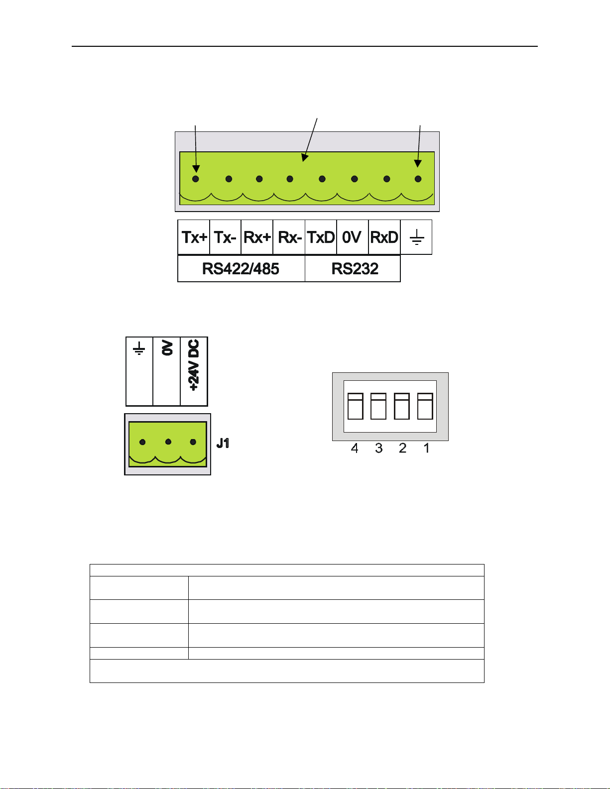
2.4 TIU050 Ports
Pin 1
igure 2.2 – Automation Equipment Serial Port
2.4.1 TIU050 Configuration of the RS-485 Port
in 8TIU050 8-pin Terminal Block
OFF
ON
SW1
Figure 2.3 – Power Connector
Powered by +24VDC and Ground.
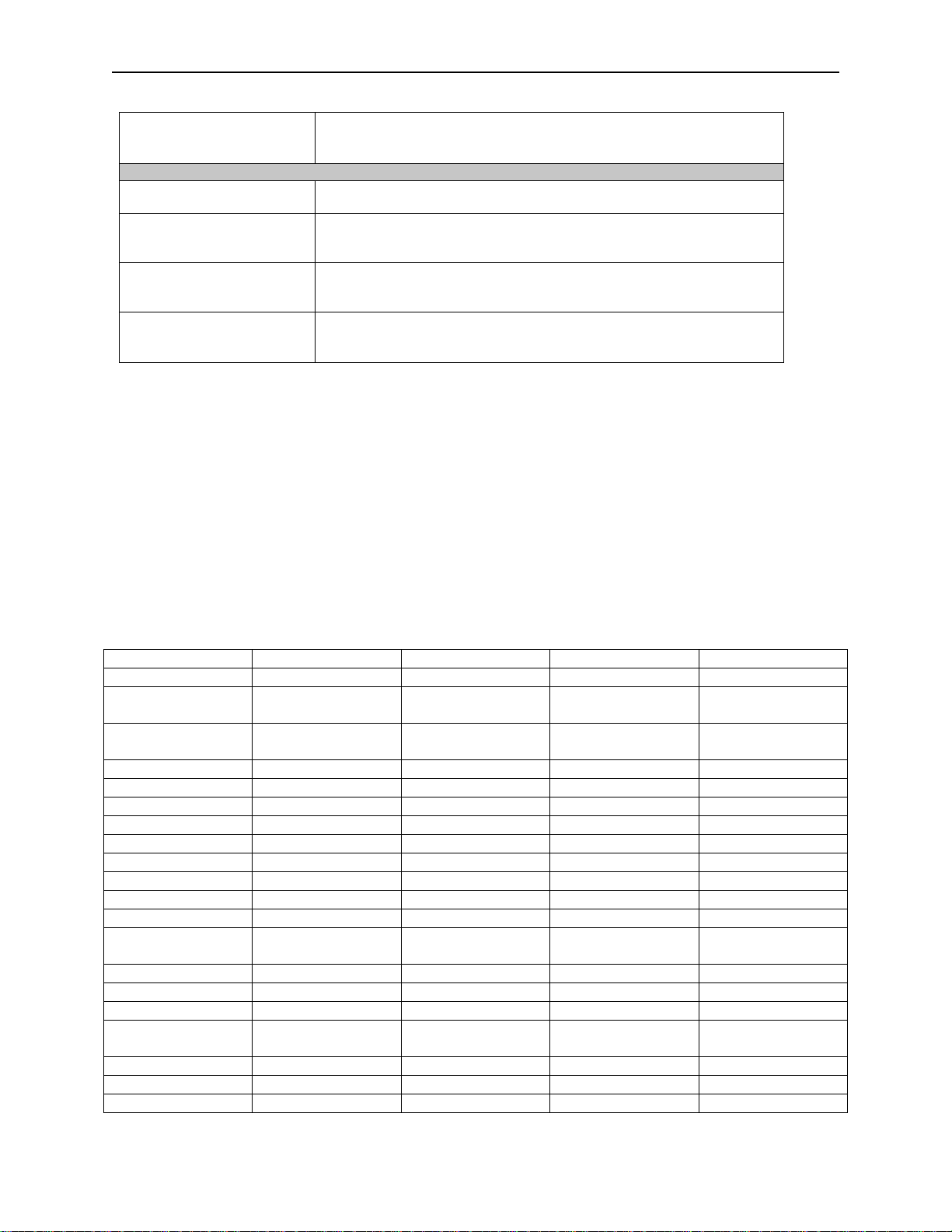
The configurat ion bank (shown in Figure 2.5) sets the parameters of the RS-485 port as described in
Table 2.1.
Table 2.1 – Configuration Bank
Switch 1 ON: Pull-up (must be used together with switch 3)
OFF: no Pull-up
Switch 2
Switch 3 ON: Pull-down (must be used together with switc h 1)
Switch 4 Reserved for future use
NOTE:
used or neither i s used.
Switch 1 and 3 must be used together. Either both pull-up and pull-down are
ON: 120Ω termination
OFF: no terminati on
OFF: no Pull-down
Figure 2.4 – Configuration Bank
Page 16

CH.2: TIU050 06 Apr 2000 PAGE 17
GFK-1819
Pull-up
and
Pull-down
switches are used to incr ease the si gnal level on the RS-485 bus. This is usef ul if
there is a long bus and a signifi c ant amount of attenuation i s anti ci pated.
Termination
resistance of 120Ω must be placed across each end of the RS-485 bus. Wit h swit c h 2 ON,
a 120Ω resistance is placed across the bus. This is only used if the TIU050/100/110 is the last device at
either end of the bus.
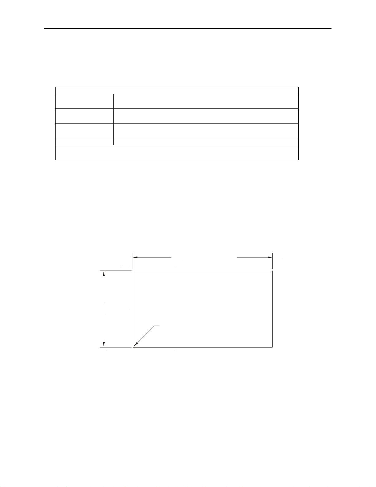
2.5 TIU050 Dimensions
5.95” [151mm]
+0.02
3.27 ” [83 mm]
-0. 0 0
+0.5
-0. 0
UP TO 0.04”[1mm] CORNER
RADIUS IS ACCEPTABLE
TIU050 CUTO UT D ETAILS
TOLERANCES ARE +/- 0.01” [0.3mm] UNLESS STATED OTHERWISE
Figure 2.5 – TIU050 Cutout
Page 17

PAGE 18 06 Apr 2000 CH. 2: TIU050
GFK-1819
NOTES
Page 18

CH. 3: TIU100/101/102/103 06 Apr 2000 PAGE 19
E
D
GFK-1819
CHAPTER 3: TIU100/101/102/103
3.1 Scope
The TIU10X 128 x 64 pixel display , which allows for some graphics and various fonts to be displayed. .
The hardware description is detailed in thi s chapter.
PAUSE Key
UP Key
Figure 3.1 - Front View of TIU100
3.2 TIU10X Button Selection Actio ns
a)
PAUSE
b)
PAUSE & DOWN
c)
PAUSE & UP
d)
UP
e)
DOWN
f)
ENTER
3.3 TIU10X Contrast Adjustment
On menu page 1 (after the start - up screen) , hold the
adjust the contrast. The contrast setting is stored and not lost after removi ng power.
key selects data f or editing OR exits from data editing.
keys pressed together, enters sub menu pages.
keys pressed together, ex its sub menus to the parent menu pages.
key selects the prev ious menu page, sub menu page, alarms, and increm ents data
key selects the next menu page, sub menu page, alarms and also decrement s data.
key sends data to the automation equipment, accepts alarms, and displays accepted alarms.
OWN Key
ENTER
key and press the UP or
NTER Key
DOWN
key to
CONTRAST BAND - allows the user to set the l ower and upper limits of contrast. Adjust the lower limit
using the UP or DOWN key and press Enter when done. Do the same for the upper limit.
WARNING: - Changes to the lower or upper limits may allow the user to set the contrast to a setting
where the display may appear blank. It is recommended that t he factory setting are used (Min 8A, Max
FE).
Page 19

PAGE 20 06 Apr 2000 CH.3: TIU100/101/102/103
T
GFK-1819
3.4 TIUX Rear View
3.5 TIU100 Ports
Pin 1
Pin 1
Figure 3.2 – Rear View of TIU100/101/102
To P C
Rx Pin 2
Tx Pin 3
0V Pin 5
Pin 1
IU100 13-pin Terminal Bl oc k
Pin 13
Page 20

CH. 3: TIU100/101/102/103 06 Apr 2000 PAGE 21
GFK-1819
Rx
Tx
Serial Port
Figure 3.4 – Automation
Equipment Port Receive &
Transm it L EDs
The LED’s flash when the TIU10X
is communicating with the AE.
Figure 3.3 – Automation Equipment Serial Port
3.5.1 TIU10X Configuration of the RS-485 Port
The configurat ion bank (shown in Figure 3.8) sets the parameters of the RS-485 port as described in
Table 3.1.
Table 3.1 – Configuration Bank
Switch 1 ON: Pull-up (m ust be used together with switch 3)
OFF: no Pull-up
Switch 2
Switch 3 ON: Pull-down (m ust be used together with switch 1)
Switch 4 Reserved for future use
NOTE:
used or neither i s used.
Switch 1 and 3 must be used together. Either both pull-up and pull-down are
ON: 120Ω termination
OFF: no terminati on
OFF: no Pull-down
Figure 3.5 – PC Port Receive &
PC Port
Transm it L EDs
The LED’s flash when the PC is
communicating with the TIU10X
Rx
Tx
Pull-up
there is a long bus and a signifi c ant amount of attenuation i s anti ci pated.
and
Pull-down
switches are used to incr ease the si gnal level on the RS-485 bus. This is usef ul if
Page 21

PAGE 22 06 Apr 2000 CH.3: TIU100/101/102/103
GFK-1819
OFF
ON
SW1
Figure 3.6 – Power Connector
Figure 3.7 – Configuration Bank
Powered by +24VDC and Ground.
Termination
resistance of 120Ω must be placed across each end of the RS-485 bus. Wit h swit c h 2 ON,
a 120Ω resistance is placed across the bus. This should only be used if the TI U050/100/110 is the last
device at either end of the bus.
3.6 TIU10X Dimensions
+0.02
3.94” [100 mm ]
-0.0 0
+0.5
-0.0
+0.02
-0.0 0
+0.5
-0.0
3.27” [83 mm]
UP TO 0.04”[1mm] CORNER
RADIUS IS ACCEPTABLE
TIU10X CUTOUT DETAILS
TOLERANC ES ARE +/- 0 .01” [0.3mm] UNLESS STATED OTHERWISE
Figure 3.8 – TIU10X Cutout
Page 22

CH. 4: TIU110/111/112/113 06 Apr 2000 PAGE 23
N
P
F
GFK-1819
CHAPTER 4: TIU110/111/112/113
4.1 Scope
The TIU11X 128 x 64 pixel display , which allows for some graphics and various fonts to be displayed.
The hardware description is detailed in thi s chapter.
QZ_
GHI
PRS7TUV8WXY
Del
ABC
1
JKL
4
.
DEF
2
5
3
MNO
6
9
+/-
umeric Keypad
rogrammable
unction Keys
Figure 4.1 – Front View of TIU110
4.2 TIU11X Button Selection Actio ns
a)
PAUSE
b)
PAUSE & DOWN
c)
PAUSE & UP
d)
UP
e)
DOWN
f)
ENTER
g)
ALPHANUMERIC KEYPAD
key selects data f or editing OR exits from data editing.
keys pressed together, enters sub menu pages.
keys pressed together, ex its sub menus to the parent menu pages.
key selects the prev ious menu page, sub menu page, alarms, and increm ents data
key selects the next menu page, sub menu page, alarms and also decrement s data.
key sends data to the automation equipment, accepts alarms, and displays accepted alarms.
and
PROGRAMMABLE KEYS
can be used to enter data or can be
used to preform some pr e- pr ogr ammed action.
4.3 TIU11X Contrast Adjustment
On menu page 1 (after the start - up screen) , hold the
ENTER
key and press the UP or
adjust the contrast. The contrast setting is stored and not lost after removi ng power.
DOWN
key to
CONTRAST BAND - allows the user to set the l ower and upper limits of contrast. Adjust the lower limit
using the UP or DOWN key and press Enter when done. Do the same for the upper limit.
WARNING: - Changes to the lower or upper limits may allow the user to set the contrast to a setting
where the display may appear blank. It is recommended that t he factory setting are used (Min 8A, Max
FE).
Page 23

PAGE 24 06 Apr 2000 CH. 4: TIU110/111/112/113
T
GFK-1819
4.4 TIU11X Rear View
4.5
TIU110 Ports
Pin 1
Pin 1
Figure 4.2 – Rear View of TIU11X
To P C
Rx Pin 2
Tx Pin 3
0V Pin 5
Pin 1
IU110 13-pin Terminal Bl oc k
Pin 13
Figure 4.3 – Automation Equipment Serial Port
Page 24

CH. 4: TIU110/111/112/113 06 Apr 2000 PAGE 25
GFK-1819
Rx
Tx
Serial Port
Figure 4.4 – Automation
Equipment Port Receive &
Transm i t LEDs
The LED’s flash when the TIU110
is communicating with the AE.
Rx
Tx
PC Port
Figure 4.5 – PC Port Receive &
Transm i t LEDs
The LED’s flash when the PC is
communicating with the TIU110
OFF
ON
Figure 4.6 – Power Connector
Powered by +24VDC and Ground.
SW1
Figure 4.7 – Configuration Bank
Page 25
PAGE 26 06 Apr 2000 CH. 4: TIU110/111/112/113
GFK-1819
4.5.1 TIU11X Configuration of the RS-485 Port
The configurat ion bank (shown in Figure 4.8) sets the parameters of the RS-485 port as described in
Table 4.1.
Table 4.1 – Configuration Bank
Switch 1 ON: Pull - up (must be used together with switch 3)
OFF: no Pull-up
Switch 2
ON: 120Ω termination
OFF: no terminati on
Switch 3 ON: Pull - down (must be used together with switch 1)
OFF: no Pull-down
Switch 4 Reserved for future use
NOTE:
Switch 1 and 3 must be used together. Either both pull-up and pull-down are
used or neither i s used.
Pull-up
and
Pull-down
switches are used to incr ease the si gnal level on the RS-485 bus. This is usef ul if
there is a long bus and a signifi c ant amount of attenuation i s anti ci pated.
Termination
resistance of 120Ω must be placed across each end of the RS-485 bus. Wit h swit c h 2 ON,
a 120Ω resistance is placed across the bus. This should only be used if the TI U050/100/110 is the last
device at either end of the bus.
4.6 TIU11X Dimensions
5.95” [151mm]
+0.02
3.27” [83 mm]
-0. 0 0
+0.5
-0. 0
UP TO 0.04”[1mm] CORNER
RADIUS IS ACCEPTABLE
TIU11X C UTO UT DE TAILS
TOLERANCES A RE + /- 0.01” [0.3mm] UNLESS STATED OT H ERW ISE
Figure 4.8 – TIU11X Cutout
Page 26

CH. 5: TIU200/201/202/203 06 Apr 2000 PAGE 27
GFK-1819
CHAPTER 5: TIU200/201/202/203
5.1 Scope
The TIU20X is 240 x 128 pixel displ ay whic h allows for full graphic screen. The hardware description is
cover under the followi ng c hapter
F9 F10 F11 F13F12
F14 F15 F16 F17 F18
Figure 5.1 – Front View of TIU20X
5.2 TIU20X Button Selection Actio ns
a)
PAUSE
b)
PAUSE & DOWN
c)
PAUSE & UP
d)
UP
e)
DOWN
f)
ENTER
g)
ALPHANUMERIC KEYPAD
h)
PROGRAMMABLE KEYS
key selects data f or editing OR exits from data editing.
keys pressed together, enters sub menu pages.
keys pressed together, ex its sub menus to the parent menu pages.
key selects the prev ious menu page, sub menu page, alarms, and increm ents data
key selects the next menu page, sub menu page, alarms and also decrement s data.
key sends data to the automation equipment, accepts alarms, and displays accepted alarms.
can be used to enter data
can be used to preform some pre-pr ogr ammed action.
QZ
1
GHI4JKL5MNO
ABC
2
DEF
3
6
PRS7TUV8WXY
9
.
Del
SPACE
0
0
+/-
NEXT
Page 27
PAGE 28 06 Apr 2000 CH. 5: TIU200/201/202/203
P
GFK-1819
5.3 TIU20X Contrast Adjustment
On menu page 1 (after the start - up screen) , hold the
adjust the contrast. The contrast setting is stored and not lost after removi ng power.
CONTRAST BAND - allows the user to set the l ower and upper limits of contrast. Adjust the lower limit
using the UP or DOWN key and press Enter when done. Do the same for the upper limit.
WARNING: - Changes to the lower or upper limits may allow the user to set the contrast to a setting
where the display may appear blank. It is recommended that t he factory setting are used (Min 8A, Max
FE).
5.4 TIU20X Rear View
ENTER
key and press the UP or
DOWN
key to
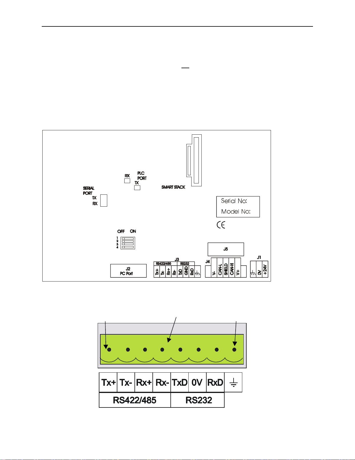
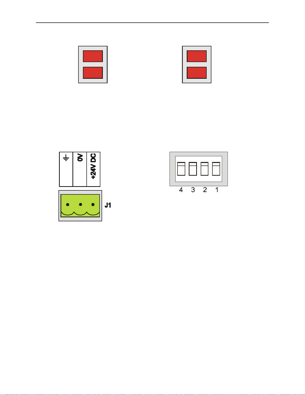
5.5 TIU20X Ports
Pin 1
6HULDO 1R
0RGHO 1R
Figure 5.2 – Rear View of TIU20X
in 8TIU20X 8-pin Terminal Block
Figure 5.3 Automated Equipment Serial Port
Page 28
CH. 5: TIU200/201/202/203 06 Apr 2000 PAGE 29
GFK-1819
Rx
Tx
Serial Port
Figure 5.4 – Automation
Equipment Port Receive &
Transm i t LEDs
The LED’s flash when the TIU20X
is communicating with the AE.
Rx
Tx
PC Port
Figure 5.5 – PC Port Receive &
Transm i t LEDs
The LED’s flash when the PC is
communicating with the TIU20X
OFF
ON
SW1
Figure 5.6 – Power Connector
Powered by +24VDC and Ground.
Figure 5.7 – Configuration Bank
Page 29

PAGE 30 06 Apr 2000 CH. 5: TIU200/201/202/203
+
-
GFK-1819
5.5.1 TIU20X Configuration of the RS-485 Port
The configurat ion bank (shown in Figure 2.23) sets the parameters of the RS-485 port as described in
Table 5.1.
Table 5.1 – Configuration Bank
Switch 1 O N: Pull-up (must be used together with switch 3)
OFF: no Pull-up
Switch 2
ON: 120Ω termination
OFF: no terminati on
Switch 3 O N: Pull-down (must be used together with switch 1)
OFF: no Pull-down
Switch 4 Reserved for future use
NOTE:
Switch 1 and 3 must be used together. Either both pull-up and pull-down are
used or neither i s used.
Pull-up
and
Pull-down
switches are used to incr ease the si gnal level on the RS-485 bus. This is usef ul if
there is a long bus and a signifi c ant amount of attenuation i s anti ci pated.
Termination
resistance of 120Ω must be placed across each end of the RS-485 bus. Wit h swit c h 2 ON,
a 120Ω resistance is placed across the bus. This should only be used if the TI U050/10X/11X/20X is the
last devic e at eit her end of the bus.
5.6 TIU20X Dimensions
0.02
µ > PP@
0.00
+0.02
µ >
-0.00
+0.5
-0.0
83 72 µ &RUQHU >5$',86 ,6 $&&(37$%/(PP@
7,8; &87287 '(7$,/6
72/(5$1&(6 $5( µ >PP@ 81/(66 67$7(' 27+(5:,6(
Figure 5.8 – TIU20X Cutout
Page 30

CH. 6: COMMUNICATIONS 06 Apr 2000 PAGE 31
GFK-1819
CHAPTER 6: COMMUNICATIONS
6.1 PC to Operator Station Communi cation s
The serial pin connect ions for transmit (Tx ), r ec eiv e (Rx) and ground are displayed below.
1
TIU1X X PC
2 T x 2 Rx
3 R x 3 Tx
5
Figure 6.1 – PC Programming Serial Port & Connect io n Detail
6.2 Automation Equipment (AE) Communications Connections
6.2.1 Recommended Automat i on E quipm ent Communication Cables
Horner Electric r ec ommends the following cables for automation equipment communication:
Belden No. 8105, 9807 or 9832 – Gener al P ur pose
Belden No. 8165 – Heavy Noise Environment
6.3 RS-232 Connection
5 0V 5 0V
TIU 110/100
RS232
(Section of 13-pin
Term inal Block)
RS232
TxD
RxD
0V
6
7
8
AE
Rx
0V
Tx
TIU050/101/102/103/111/112/113/20X
RS232
(Section of 8-pin
Term inal Block)
RS232
TxD
RxD
5
0V
6
7
Figure 6.2 – RS-232 Connection
AE
Tx
Rx
0V
Page 31

PAGE 32 06 Apr 2000 CH. 6: COMMUNICATIONS
GFK-1819
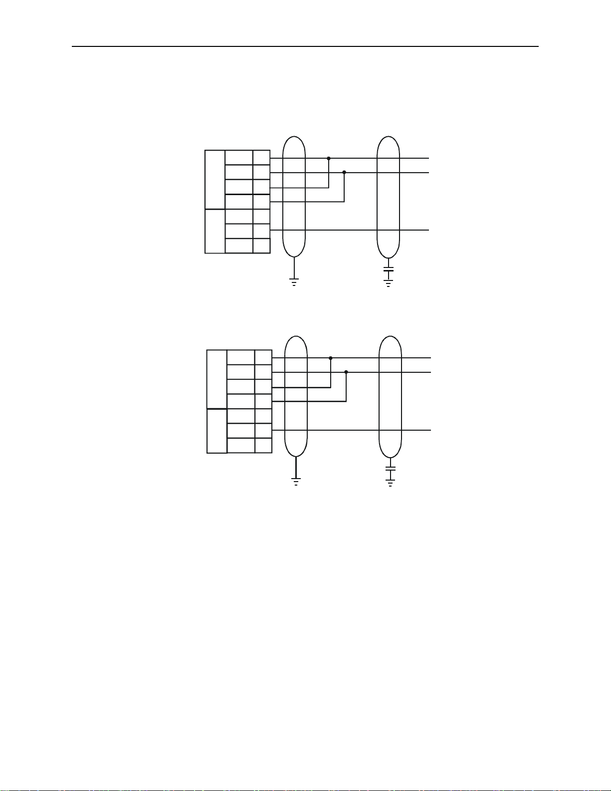
6.4 RS-422/485 Four-Wire
TIU110/100
(Section o f 13 -pin
Term inal Block)
RS422/485
(4 -wire )
TIU050/101/102/103/111/112/113/20X
RS 422 /485
RS232
Tx+
Tx-
Rx+
RxTxD
0V 7
RxD
2
3
4
5
6
8
0.1uF Ce ram ic
Automated E q uipm en t
RS 42 2/48 5 Conn ections
See Note Below
(Section o f 8-pin
Term inal Block)
RS 422 /485
RS422/485
(4 -wire )
The descriptions used by different manuf actur er s f or RS - 422/485 connections vary. Please refer to
Note:
the automation equipment manufactur er s own manuals for connection detail s.
Horner produces appli c ation notes explaining the connection to each of the differ ent aut om ated
Note:
equipment manufactures. These applic ation notes are ongoing, see your installation CD for any released
documentation.
RS232
Figure 6.2 – RS-422/485 Four-Wir e
Tx+
Tx-
Rx+
RxTxD
0V 6
RxD
1
2
3
4
5
7
0.1uF Ce ram ic
Automated E q uipm en t
RS 42 2/48 5 Conn ections
See Note Below
Page 32
CH. 6: COMMUNICATIONS 06 Apr 2000 PAGE 33
GFK-1819
6.5 RS-485 Two-Wire
TIU110/100
RS422/485
(2 -w ire )
TIU050/101/102/103/111/112/113/20X
RS422/485
(2 -w ire )
RS4 22/485
RS232
RS422 /485
RS232
Tx+
TxRx+
RxTxD
0V
RxD 8
Tx+
TxRx+
RxTxD
0V
RxD 7
AE
2
3
4
5
6
7
0.1uF Ceramic
1
2
3
4
5
6
Tx/Rx+
Tx/Rx-
COM
AE
Tx/Rx+
Tx/Rx-
COM
Figure 6.3 – RS-485 Two-Wire
0.1uF Ceramic
Page 33

PAGE 34 06 Apr 2000 CH. 6: COMMUNICATIONS
GFK-1819
6.6 Current Loop
The following diagr am shows the connection to a devic e with an active 20mA current loop. The current
loop on the TIU100/110 is passive. Either the PLC must provide t he 20m A source or an ex ternal current
source must be suppli ed.
20mA Loo p
T+
9
T-
20m A Loop
Note: Current Loop is not a standard option on the T IU100/ 110
specifical ly or can be re-fit into a standard unit. Contact a Horner El ec tric dealer for more information.
Note: Current Loop is not an option with the TIU050/ 101/102/103/111/112/ 113/20X.
10
R+
11
R-
12
Figure 6.4 – Current Loop
. Current loop must be ordered
+
ST
SR
-
Page 34

CH. 7: GETTING STARTED 06 Apr 2000 PAGE 35
GFK-1819
CHAPTER 7: GETTING STARTED
7.1 Self-Test
Power up the unit wit h the UP and
ENTER
mode. The self-test c onsi sts of the following four check s:
7.1.1 Contrast Band
This test allows t he user to set the lower and upper limits of contrast. Adjust the lower limit using the
key and press
Enter
when done. Do the sam e for the upper limit.
WARNING: - Changes to the lower or upp er li mits may allow the user to set the contrast to a
setting where the displ ay may app ear bl ank. It is recommended that the factory setting are used
(Min 8A, Max FE).
7.1.2 Display Test
The display test continuously blinks all pix els on (black) to off. Look for any pixels stuck on or off. Exit
this test by pressing and holding any key for approximately two seconds.
7.1.3 Keyboard Test
As each key is pressed, an indi c ation
keypad, press the key and a message appears indicating the key press. Check for keys indicati ng
multiple presses or not r epor ting presses. Exit this test by pr essing and holding any key for
approximately two seconds.
keys pressed at the same time. The unit ent er s a self - test
UP
appears above that key. In the case of units with a numeric
***
or
DOWN
7.1.4 RAM Test
Test either segment 0000 or segment 1000 (on the TIU100/ 110) of t he RAM. The segment 1000 t est
performs a base 3 repeating test. This test detects shorted addres s l ines and damaged memory bits.
The segment 0000 test performs a Read-Modify-Write test on each byte of RAM, detecting dam aged
memory bits. Exit this test by selecting DONE.
7.1.5 Serial Loop-back Test s
Tests the PC port and the Serial P or t in each of it’s three modes for serial loop-back. Pre-made plugs are
required to link the pins of a particular port. This takes the following form:
Table 7.1 Loop-back Test Plugs
Port Tested Produc t Type of Connector Pins to Short
PC (J2) TIU100/110 Pin male D link connector pin 2 to pin 3
RS-232 (J3) TI U100/110 13-pin phoenix connecti on pin 6 to pin 8
RS-422/485 (J3) TIU100/110 13-pin phoenix connec tion pin 2 to pin 4 and pin 3
to pin 5.
Current Loop TIU100/110 13-pin phoenix connecti on pin 1 to 9, pin 10 to 11
and pin 12 to 7
PC TIU050/101/102/1
Pin male D link connector pin 2 to pin 3
03/112/113/20X
RS-232 TIU050/101/102/1
8-pin phoenix c onnection Pin 5 to pin 7
03/112/113/20X
RS-422/485 TIU050/101/102/1
03/112/113/20X
NOTE:
current loop in not installed on standard models, as such a standard model will fail the
8-pin phoenix c onnection Pin 1 to pin 3, Pin 2 to
pin 4
current loop-back test. Current Loop is not an opti on on the TI U050/20X.
After starting the test, the OK counter begins to count up. Exit this test by selecting
DONE
.
Page 35

PAGE 36 06 Apr 2000 CH. 7: GETTI NG STARTED
_
.
T
GFK-1819
7.2 Updating the Protocol
When the software is i nstalled the user decides where the m ain CB REEZE folder resides. During
install ation the following folder s are cr eated: -
In the protocol directory 3 folders are creat ed, TIU0xx, TIU1xx and TIU2xx. The protoc ol files for the
different t erminal is loaded into these folders. The protocol files for the TIU050 are loaded into Tiu0xx, the
protocol files for the TIU10X are loaded into Tiu10x and the protocol files for t he TIU20X are loaded into
Tiu20x.
The name of the protoc ol file is broken up into three section, the protocol, the main software revsion and
the terminal type that protocol file is for.
Protocol Name
Example
snp_R4.1xx
This is the protocol file for release 4 software for the GE FANUC P LC, for the TIU10X
df1_R4.2xx
This is the protocol file for release 4 software for Allen Brabley PLC, for the TIU20X
To Update Protoc ol File
1. Set Terminal Type
2. Set the required Automation Equipment in Communic ations Settings
3. Select
4. Select the folder of the terminal you have connected to t he PC. The cor r ect file will appear for the
terminal type sel ec ted and the Automation Equipment sel ec ted. Select that file and cli c k OK.
5. A status bar appears indic ating download progress.
6. After the transfer, the TIU050/10X/11X/20X resets itself. The correct P LC type i s di spl ay ed on the
TIU050/10X/11X/20X.
7. Next, the project loaded runs.
7.3 Updating the Operating System
1. Select
2. Choose the updated file with the “BIN” extension. Click OK.
3. A status bar appears indic ating download progress.
4. During the download proc es s, TIU050/10X/11X/20X displays the message “
Update TIU Protocol
Update Operating System
Software Revision
menu.
from the
ile
F
from the
ile
F
erm ina l Ty pe
menu.
SYSTEM SHUTDOWN
”.
Page 36

CH. 8: NETWORKS 06 Apr 2000 PAGE 37
GFK-1819
CHAPTER 8 : NETWORKS
8.1 Scope
This chapter giv es a brief introduction int o the net working hardware available on the Operator Station
range. The part numbers of the various options are av ailable in the Introduction Chapt er of t his manual.
For information on programming the various network options see GFK-1818, User Manual for the
CBREEZE Software.
8.2 Controller Area Netwo rk ( CAN) Overview
The controller area network (or CAN bus) is a serial communications bus that was originall y developed in
the late 1980’s by a German com pany (Robert B osch) for use in the automotive industry. CAN is an ISO
(International Standards Organisation) - defined serial communications bus for real-time appli c ations.
Established i n 1947, the International Standards Or ganisation (I SO) i s a multi national body dedicat ed to
worldwide agreement on international standar ds. S pec ifically, CAN is document ed in ISO 11898 (for
high-speed appli c ations) and ISO 11519 (for lower-speed applications).
8.2.1 CAN Features
CAN-based open autom ation technology successfully competes on the market of distr ibuted automation
systems because of the speci al features of the CAN protocol. T he special features are CAN’s producerconsumer-oriented (or peer-to-peer) principle of data transmi ssion and its multi-master c apability. The
general design of CAN originally specifi ed a high bit rate, high immunity to electri c al interference and an
ability to detect any er r or s produced. CAN networks have the foll owi ng gener al attributes:
•
Automatic er r or detec tion
•
Easily configurable
•
Cost-effective to design and implement
•
Capable of operating in harsh environments
8.3 CsCAN Network Overview
The CsCAN Network was fi r st dev eloped in 1993 by Horner Electric. It was developed for use in a project
that Horner Electr ic completed for the United States Post Office. Horner Electric dev eloped its own
network, because i t needed a network that had a specific set of powerful peer-to-peer and host- to-node
capabiliti es. The CsCAN Net work has a “pass-through” feature whereby PC- base d pr ogr ams access
other nodes connected to a network by passing the programming command through the serial por t to the
network port. (For a more detailed description, see below.) Horner Electric found that by developing its
own network, it sati sfied several important needs. Hor ner Electric continues CsCAN Net work
development t o sati sfy the requirements of today and the requirements of the future.
8.3.1 CsCAN Network Features
The CsCAN Network is based on CAN, which has many desi r able features such as ruggedness, ease of
configuration, etc. With Horner Electric Controllers, data is passed at 125Kbp s using a dif ferential pair of
wires plus a ground. It is important to note that the data rate is not limit ed to 125Kbps. The maximum
data rate is 1Mbps (limited by the speed of light). The CAN implementation in the CsCAN controller
allows up to 64 controllers to be networked with no additi onal hardware and up to 253 controllers with
three CAN repeaters.
For the programmer, little knowledge of networking procedures is needed. Howev er for troubleshooting
and optimizing, the following inform ation is helpful. Instead of usi ng m aster /slave or token passing, the
hardware self-arbitrates based on the Network ID.
given a higher prio rity than controllers with higher Netwo rk ID numbers.
Controllers with lower Network ID numbers are
8.3.2 CsCAN Network Operation
When a controller needs to send data over the network, it fir st waits for the network to be idle (curr ently a
maximum of 900uS). If two controllers start broadcasting information on t he network at the same time, the
Page 37

PAGE 38 06 Apr 2000 CH. 8: NETWORKS
GFK-1819
"self-arbitration" causes the controller with the greater Network ID number to cease broadcasting without
affecting t he message-in-progress of the ot her controller.
In applications wit h a large number of networked cont r ollers, better result s may be achieved by assigning
lower Network IDs to contr ollers that have more critical network data than other controllers. By assigning
higher Network IDs to c ontrollers that provide num er ous network updat es, the control lers are prevented
from monopolising the bus time.
Each controll er is capable of broadcasting Gl obal Digital Output bits (%QG) and Global Analog Output
bits (%AQG), which ar e peri odically broadcasted to the other controllers on the net work. The coil
representations %QG and %AQG may be used in CBREEZE like any other coil or i nternal register
reference.
All digital global outputs are broadcast to the net work eac h time one of them has a state change. In
addition, if a cont roller has not transmitted its global data for specifi c tim e peri od, the controller's
programmable network timer may expire, whic h in turn r esul ts in a global data broadcast. Finally, as part
of its power-up initialisation sequence, another controll er can ex plicitly request a controller to broadcast
its global dat a.
8.4 DeviceNet Overview
DeviceNet is an open network. The specification and the protocol are open. Vendors are not required to
purchase hardware, software or licensing rights to connect devic es to a system.
8.4.1 DeviceNet Features
DeviceNet is a low-cost communications li nk to connect i ndustr ial devices. It allows the interchangeabilit y
of simple devi c es whil e making interconnectiv i ty of mor e complex devices possible. Devic eNet is based
on CAN. It is an applicati on lay er pr otocol (ISO layer 7) and is defined i n term s of an abstract object
model, which r epr esents the available communication services and the exter nal v isible behaviour of a
DeviceNet node.
The DeviceNet Model is appl ication independent. Dev ic eNet provides the communication services
needed by various types of applications. Many of today ' s l ower level industrial cont r ol dev ic es must retain
their low cost/low resource characteristics even when directly c onnec ted to a network. DeviceNet takes
this into consider ation by defining a specific instanc e of the DeviceNet Model for comm unic ations typically
seen in a Master/Slave application. Thi s is refer r ed to as the Predefined Master/Slave Connection Set.
Some of the features and functionality of the Devic eNet network are described Tabl e 8.1.
Table 8.1 - DeviceNet F eatures and Functionality
Network Size Up to 64 Nodes
Network Length Selec table end-to end network distanc e v aries with speed
Baud Rate Distance
125 Kbps 500m (1,640 feet)
250 Kbps 250m (820 feet)
500 Kbps 100m (328 feet)
Data Packets 0-8 bytes
Bus Topology Linear (tr unkli ne/dropline); power and signal on the same network cable
Bus Addressing Peer-t o- P eer with Multi-Cast (one-to-many); Multi-Master and Master /Slave
special case; polled or change-of-stat e ( ex ception-based)
System
Features
Removal and replacement of devices from the network under power
Page 38

CH. 8: NETWORKS 06 Apr 2000 PAGE 39
GFK-1819
8.4.2 DeviceNet Protocol
Some of the communication protocol features of Devic eNet consist of the following:
1. A DeviceNet product can behave as a Client, a Server or both.
2. Master/Slave operation.
3. Capable of Peer-to-Peer exchange capability exists in which any Devic eNet product can produce and
consume messages.
4. Capable of supporting 64 node addresses
5. Each node can support an unlim ited number of I/O.
8.4.3 DeviceNet Operat ion
The following r estr ic tions are placed on operations when using an O S that is configured as a
DeviceNet slav e.
1. Currently, c ommunication between the PC and the contr oller is only possible to the device physically
connected to the PCs’ serial por t. Project downloads, upl oads, monitoring, and configuration
currently take place
2. The HE200CGM40x gat eway car d c an not cur r ently be used with DeviceNet communications.
Horner Electric is providing a special Gateway device that is based on the OCS hardware. The
Gateway device m ak es it possible to connect the PC serial port wit h the DeviceNet network.
3. DeviceNet net work nodes are in a range from 0 to 63. The controller is able to observe network
responses (poll ed c onnec tions) from any slave to the Devi ceNet Master. The first 16-words of these
observed responses are made available for mappi ng on the
These correspond to t he av ailable nodes 0 to 63 and registers AQG1 to AQG16. Node 64 is used for
a special case. W hen data is sent to a controller from a DeviceNet Master (via the polled connection)
this data is mapped to node 64. Relative addressing is limited to -64 to +64.
over a DeviceNet network.
Network Input Assignments
cannot
page.
Page 39

PAGE 40 06 Apr 2000 CH. 8: NETWORKS
GFK-1819
8.5 CAN Wiring Rules
V-
CN_L
SHIELD
CN_H
V+
V-
CN_L
SHIELD
CN_H
V+
V-
CN_L
SHIELD
CN_H
V+
V-
CN_L
SHIELD
CN_H
V+
121
Ω
121
Ω
+
12-25VDC
-
V+
CN_H
CN_LV-SHIELD
BLK
Ω
BLU
BLK
121
RED
RED
WHT
SH IE LD
BLK
BLU
BLU
WHT
WHT
RED
RED
CN_LV-SHIELD
V+
CN_H
SHIE LD
BLK
BLK
BLU
BLU
WHT
WHT
RED
RED
CN_LV-SHIELD
V+
CN_H
SHIE LD
CN_LV-SHIELD
Ω
121
BLU
BLK
-
+
12-25VDC
1. Wire the CAN network in a daisy-c hained fashion such that there ar e ex actly two physical end-points
on the network.
2. The two nodes at the physical end-points need to have 121 ohm 1% terminating resistors connected
across the CN_L and CN_H terminals.
3. Use data conductors (CN_L and CN_H) that are 24 AWG shielded twisted pair for “thin cable” and 22
AWG shielded twisted pai r for “thick cable”. They must also have 120-ohm c har acteristic impedance.
In typical industrial environments, use a Belden wire #3084A (“thin”). Use #3082A (“thick”) fo r
environment s where noise is a concer n.
4. Use power conductors (V- and V+ ) that are 18 AWG twisted-pair for “thin cable” and 15 AWG twisted-
pair for “thick cable”.
5. Connect the V- power conductor to a good earth ground
physical endpoints.
6. For a section of c able between two nodes, the cable shield is connected to the cable shield input at
one end of the cable only.
7. A CAN network (without r epeaters) is limited to 64 nodes (with 63 cable segments) with a maximum
cable length of 1500 ft.
8. Up to four CAN network segment s, whic h adher e to the above rules, may be connect ed together
using three CAN repeaters. In this manner, a CAN network may be extended to 253 nodes with a
total cable distanc e of 6000 ft.
Figure 8.3 – CAN Network Cabling
at one place only
on the network, preferably
V+
CN_H
RED
WHT
Page 40

CH. 8: NETWORKS 06 Apr 2000 PAGE 41
GFK-1819
8.6 Profibus
Profibus utilises a Master-Slave type of c ommunication with the TIUXX2 functioning as a slave device.
Decentralised Peripherals (Sl av e) Baud r ates of up to 12 MBd can be obtained through Profibus.
Up to 32 devices 9master or sl av es) can be c onnected in one segment without usi ng r epeaters, or up to
64 devices can be connect ed usi ng r epeaters.
Master devices are used to det ermine the data communi c ation on the bus. One master can service
several slav es. S ev er al M aster s can par ticipate on the bus simultaneously, but only one Master can write
outputs to a slave.
The slave devices are peripheral devices. Sl av es do not hav e bus access rights and can only
acknowledge received messages or send messages to the master when requested to do so. Any master
can read data from the sl av e dev ic es. All connected Slaves have the same priority.
For further information on the Profibus Network, visit their website at www.profibus.com
8.6.1 Profibus Wir ing
The TIUXX2 uses a 9 pin D-sub plug connec tor for its Profibus port. T he pin assignment of the plug
connector and the wir ing are show below.
Station 1 Sta tion 2
Rxd/TxD -P 3
V+ 6
D Gnd 5
RxD/TxD -N 8
3
6
5
8
Protective G round
Figure 8.4 Profibus Port Pinout
Page 41

PAGE 42 06 Apr 2000 CH. 8: NETWORKS
GFK-1819
RxD/TxD-N 8
Its is necessary to term inate both ends of the network. B oth terminations must have power to them to
insure proper operation of the network. The following diagram illustrates the correct connection for the
terminati on resistors.
RxD/TxD-P 3
DGND 5
V+ 6
Figure 8.5 – Profibus Network Cabling
RxD/TxD-N 8
DGND 5
V+ 6
RxD/TxD-P 3
RxD/TxD-N 8
RxD/TxD-P 3
DGND 5
V+ 6
VP (6)
Lin e termin ation
390 Oh m
A-Line (3)
220 Oh m
B-Line (8)
390 Oh m
GND (5)
Figure 8.6 – Profibus termination resistors
Page 42

CH. 9: SMARTSTACK 06 Apr 2000 PAGE 43
GFK-1819
CHAPTER 9: SMARTST ACK
9.1 Scope
Horner has now added the Smar tStack modules from the OCS Range to the TIU20X range. The
SmartStack system is a method of allowing I/O expansion on an HM I. A wide range of m odul es i s
available including Digital and Anal ogue.
9.2 Installing and Removing a S mart S t ack Module
The following sect ion describes how to install and r em ove a SmartStack Module.
Caution: To function properly and avoid possible damage, do not install more than four
Smart Stack Modules per TIU20X.
9.2.1 Installing SmartStack Modules
1. Hook the tabs. Each SmartStack Module has two tabs that fit int o sl ots loc ated on the TIU20X. (The
slots on the TIU20X are located on the back cover.)
2. Press the SmartSt ac k Module into the “locked” position, making sure to align the SmartS tack Module
fasteners with t he SmartStack receptacles on t he TI U20X.
9.2.2 Removing SmartS tack Modules
1. Using a Flathead screwdriver, pry up the end of the SmartStack Module (opposite of tabs) and swing
the module out.
2. Lift out the tabs of the module.
Figure 9.1 – Installing a SmartS t ack Module in an OCS.
Page 43

PAGE 44 06 Apr 2000 CH. 9: SMARTSTACK
GFK-1819
NOTES
 Loading...