

Page 1

GE
Automation & Controls
For Public Disclosure
Programmable Control Products
PACSystems* Ethernet Switch GLM Series User Manual GFK-3030
PACSystems* PROFINET
Managed Industrial
Ethernet Switches
User Manual
GFK-3030
December 2017
Page 2
Legal Information
Warnings, Cautions, and Notes as Used in this Publication GFL-002
Warning
Warning notices are used in this publication to emphasize that hazardous voltages,
currents, temperatures, or other conditions that could cause personal injury exist in
this equipment or may be associated with its use.
In situations where inattention could cause either personal injury or damage to
equipment, a Warning notice is used.
Caution
Caution notices are used where equipment might be damaged if care is not taken.
Note: Notes merely call attention to information that is especially significant to understanding
and operating the equipment.
These instructions do not purport to cover all details or variations in equipment, nor to provide for every
possible contingency to be met during installation, operation, and maintenance. The information is supplied
for informational purposes only, and GE makes no warranty as to the accuracy of the information included
herein. Changes, modifications, and/or improvements to equipment and specifications are made periodically
and these changes may or may not be reflected herein. It is understood that GE may make changes,
modifications, or improvements to the equipment referenced herein or to the document itself at any time. This
document is intended for trained personnel familiar with the GE products referenced herein.
GE may have patents or pending patent applications covering subject matter in this document. The furnishing
of this document does not provide any license whatsoever to any of these patents.
GE PROVIDES THE FOLLOWING DOCUMENT AND THE INFORMATION INCLUDED THEREIN AS-IS AND WITHOUT
WARRANTY OF ANY KIND, EXPRESSED OR IMPLIED, INCLUDING BUT NOT LIMITED TO ANY IMPLIED STATUTORY
WARRANTY OF MERCHANTABILITY OR FITNESS FOR PARTICULAR PURPOSE.
* indicates a trademark of General Electric Company and/or its subsidiaries.
All other trademarks are the property of their respective owners.
©Copyright 2017 General Electric Company.
All Rights Reserved
Page 3

Contact Information
If you purchased this product through an Authorized Channel Partner, please contact the seller directly.
General Contact Information
Online technical support and GlobalCare
www.geautomation.com/support
Additional information
www.geautomation.com
Solution Provider
solutionprovider.ip@ge.com
Technical Support
If you have technical problems that cannot be resolved with the information in this manual, please contact us
by telephone or email, or on the web at www.geautomation.com/support
Americas
Phone
1-800-433-2682
International Americas Direct Dial
1-780-420-2010 (if toll free 800 option is unavailable)
Customer Care Email
digitalsupport@ge.com
Primary language of support
English
Europe, the Middle East, and Africa
Phone
+800-1-433-2682
EMEA Direct Dial
+ 420-296-183-331 (if toll free 800 option is unavailable or if
dialing from a mobile telephone)
Customer Care Email
digitalsupport.emea@ge.com
Primary languages of support
English, French, German, Italian, Czech, Spanish
Asia Pacific
Phone
+86-400-820-8208
+86-21-3877-7006 (India, Indonesia, and Pakistan)
Customer Care Email
digitalsupport.apac@ge.com
Primary languages of support
Chinese, Japanese, English
Page 4

GFK-3030 December 2017 i
Table of Contents
PACSystems* Ethernet Switch GLM Series User Manual GFK-3030
Table of Contents ............................................................................................................................................................... i
Table of Figures ................................................................................................................................................................ iv
Chapter 1 Introduction ................................................................................................................................................ 1
1.1 Revisions in this Manual ........................................................................................................................... 2
1.2 PACSystems Documentation ................................................................................................................... 2
Chapter 2 Overview ...................................................................................................................................................... 3
2.1 System Overview ........................................................................................................................................ 3
IO-Devices on a PROFINET Network .................................................................................................................. 3
Ethernet Devices on an Ethernet Network ..................................................................................................... 4
GLM System Capabilities ......................................................................................................................................... 4
2.2 GLM Product Differentiation .................................................................................................................... 5
2.3 GLM Features .............................................................................................................................................. 5
2.4 GLM LEDS ..................................................................................................................................................... 6
Chapter 3 Installation .................................................................................................................................................. 7
3.1 Mounting ...................................................................................................................................................... 7
DIN-Rail Mounting ....................................................................................................................................................... 7
Panel Mounting ............................................................................................................................................................. 8
3.2 Power Connection ...................................................................................................................................... 9
GLM Switch Current Draw ....................................................................................................................................... 9
3.3 Grounding .................................................................................................................................................. 10
3.4 Alarm Relay Output ................................................................................................................................. 11
3.5 Ethernet Connections .............................................................................................................................. 12
RJ45 Connections ..................................................................................................................................................... 12
SFP Connections ....................................................................................................................................................... 13
3.6 LED Operation ........................................................................................................................................... 14
3.7 System Reset ............................................................................................................................................. 15
3.8 Console Connection ................................................................................................................................. 16
Page 5

Contents
ii PACSystems PROFINET Managed Industrial Ethernet Switches User Manual GFK-3030
Chapter 4 Configuration ............................................................................................................................................ 17
4.1 Import the GSDML file ............................................................................................................................. 18
4.2 Associating the IO-Device with its Controller .................................................................................... 21
4.3 PROFINET Cyclic I/O Data ....................................................................................................................... 23
Slot 1: Device Status ................................................................................................................................................ 24
Slot 2: Port Status ...................................................................................................................................................... 24
Slot 3: Port Alarm & Port Settings & Status ................................................................................................. 25
Slot 4: MRP Group 1 Status .................................................................................................................................. 27
Slot 5: MRP Group 2 Status .................................................................................................................................. 28
Slot 6: Ring Group 1 Status .................................................................................................................................. 29
Slot 7: MRE Group 1 Status .................................................................................................................................. 29
Slot 8: MRE Group 2 Status .................................................................................................................................. 29
4.4 PROFINET Acyclic I/O Data ..................................................................................................................... 30
Acyclic Device Data –Subslot 0 ......................................................................................................................... 30
Acyclic Port Data – Subslot 1 .............................................................................................................................. 32
Acyclic MRP Group 1 Data – Subslot 2 .......................................................................................................... 33
Acyclic MRP Group 2 Data – Subslot 3 .......................................................................................................... 33
Acyclic Ring Group 1 Data – Subslot 4 .......................................................................................................... 34
Acyclic MRPe Group 1 Data – Subslot 5 ........................................................................................................ 35
Acyclic MRPe Group 2 Data – Subslot 6 ........................................................................................................ 35
4.5 Assigning Device Name and IP Address .............................................................................................. 36
4.6 MRP Settings for IO-Devices .................................................................................................................. 37
4.7 Download from PME to CPU ................................................................................................................... 38
4.8 Hot Standby CPU Redundancy Considerations .................................................................................. 38
4.9 Discovery Tool .......................................................................................................................................... 39
Chapter 5 Diagnostics................................................................................................................................................ 41
Setting up and Sensing Alarms ......................................................................................................................... 42
Power Alarm ................................................................................................................................................................ 43
5.2 External Alarm Circuit ............................................................................................................................. 44
Appendix A Command Language Interface (CLI) ........................................................................................................ 45
A-1 Operator Interface ................................................................................................................................... 45
Login ................................................................................................................................................................................ 45
Connection Interface .............................................................................................................................................. 45
Login Screen Description ...................................................................................................................................... 45
Execution Modes ....................................................................................................................................................... 46
Getting help ................................................................................................................................................................. 46
Terminal Key Function ........................................................................................................................................... 47
Notation Conventions ............................................................................................................................................. 47
Page 6

Contents
GFK-3030 December 2017 iii
A-2 Summary of Commands Descriptions.................................................................................................. 48
A-3 Command Descriptions .......................................................................................................................... 49
Initialize Mode Commands .................................................................................................................................. 49
Enable Mode Commands ..................................................................................................................................... 50
Configure Mode Commands............................................................................................................................... 71
VLAN Mode Commands ........................................................................................................................................ 91
Interface VLAN Mode Commands ................................................................................................................... 94
RingV2 Group Mode Commands ...................................................................................................................... 97
Spanning Tree Commands .................................................................................................................................. 99
sFlow Configure Commands ............................................................................................................................103
SNMP Configure Commands ............................................................................................................................105
Qos Function Commands...................................................................................................................................109
IGMP Functional Commands ............................................................................................................................113
MVR Functional Commands .............................................................................................................................115
MLD Functional Commands .............................................................................................................................119
Loop-Protection Configure Commands......................................................................................................122
LLDP Configure Commands ..............................................................................................................................123
RFC2544 Testing Configure Commands ....................................................................................................125
GVRP Configure Commands .............................................................................................................................127
Voice VLAN Configure Commands ................................................................................................................128
Profile Alarm Commands ...................................................................................................................................129
Appendix B Supported Ethernet Commands ............................................................................................................. 131
Page 7

Contents
iv PACSystems PROFINET Managed Industrial Ethernet Switches User Manual GFK-3030
Table of Figures
Figure 1: GLM064 ........................................................................................................................................................................................................1
Figure 2: GLM082 ........................................................................................................................................................................................................1
Figure 3: GLM104 ........................................................................................................................................................................................................1
Figure 4: Typical PROFINET System with GLM Switches ..........................................................................................................................3
Figure 5: GLM Switch Bottom Panel...................................................................................................................................................................5
Figure 6: Front-Panel LEDs .....................................................................................................................................................................................6
Figure 7: DIN-Rail Mounting ...................................................................................................................................................................................7
Figure 8: Panel-Mounting ........................................................................................................................................................................................8
Figure 9: Dual DC Power Input Connections..................................................................................................................................................9
Figure 10: Ground Connection ........................................................................................................................................................................... 10
Figure 11: Alarm Relay Output .......................................................................................................................................................................... 11
Figure 12: RJ45 Pinout ........................................................................................................................................................................................... 12
Figure 13: Ports 1 & 2 Copper Connections ................................................................................................................................................ 12
Figure 14: Fiber-Optic Cable with LC Duplex Connectors .................................................................................................................... 13
Figure 15: Attach Fiber-Optic Cables to Installed SFP Socket ............................................................................................................ 13
Figure 16: Console Port ......................................................................................................................................................................................... 16
Figure 17: Console Cable Wiring ....................................................................................................................................................................... 16
Figure 18: PME Toolchest Feature .................................................................................................................................................................... 18
Figure 19: Toolchest Data Types ....................................................................................................................................................................... 18
Figure 20: Select PROFINET Device .................................................................................................................................................................. 19
Figure 21: Import GSDML Command ............................................................................................................................................................. 19
Figure 22: Browse to Folder and Select GSDML file for Import ......................................................................................................... 20
Figure 23: Toolchest Displays Newly-Added Device ............................................................................................................................... 20
Figure 24: Add IO-Device to PROFINET Controller .................................................................................................................................... 21
Figure 25: Select IO-Device from PROFINET Device Catalog .............................................................................................................. 21
Figure 26: IO-Device Installed Under PNC001 ........................................................................................................................................... 22
Figure 27: Assign Starting %I & %Q References for Cyclic I/O Data ............................................................................................... 23
Figure 28: Properties of IO-Device ................................................................................................................................................................... 36
Figure 29: Inspector Form for IO-Device ....................................................................................................................................................... 36
Figure 30: Accessing the MRP Parameters of an IO-Device ................................................................................................................ 37
Figure 31: Set up MRP Ring Ports ..................................................................................................................................................................... 37
Figure 32: MRP Group2 Data Tab..................................................................................................................................................................... 37
Figure 33: Launch Discovery Tool .................................................................................................................................................................... 39
Figure 34: Discovery Tool in Progress ............................................................................................................................................................ 39
Figure 35: Listing of all Detected Devices ..................................................................................................................................................... 40
Figure 36: GLM Switch Parameters Set in PME ......................................................................................................................................... 42
Figure 37: Set Port Alarm Active or Inactive Using PME ....................................................................................................................... 42
Figure 38: External Alarm Circuit ...................................................................................................................................................................... 44
Figure 39: Login Constraints ............................................................................................................................................................................... 45
Figure 40: Telnet Login Screen ........................................................................................................................................................................... 46
Page 8
GFK-3030 December 2017 1
Chapter 1 Introduction
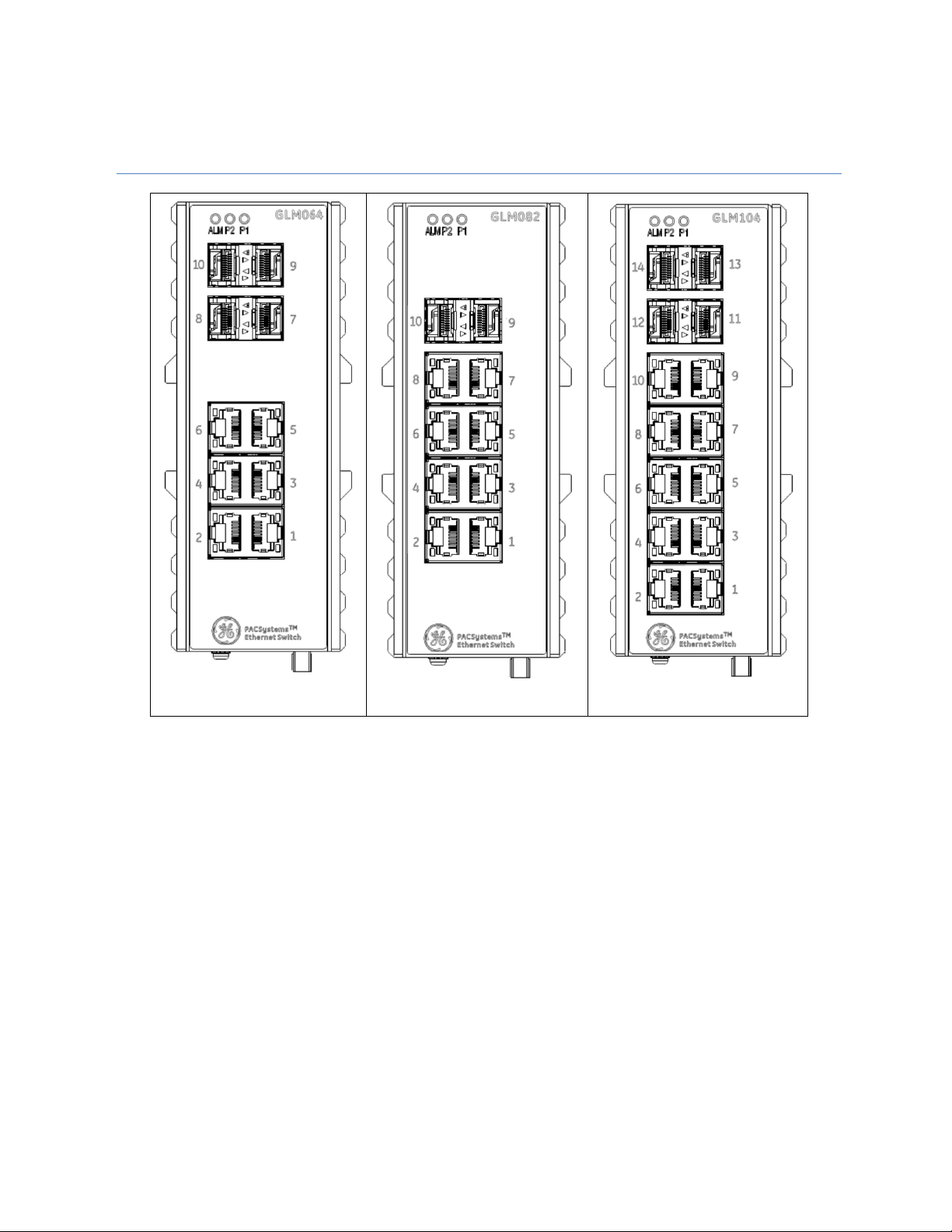
Figure 1: GLM064
Figure 2: GLM082
Figure 3: GLM104
The PACSystems GLM series Industrial Ethernet Switches deliver high quality Ethernet operation over a wide
temperature range and can tolerate an extended power input range. These switches are ideal for harsh
environments and mission critical applications. They may be DIN-rail mounted or panel-mounted.
This document includes a product overview and covers installation, configuration, operation and diagnostics.
Page 9

Chapter 1. Introduction
2 PACSystems PROFINET Managed Industrial Ethernet Switches User Manual GFK-3030
1.1 Revisions in this Manual
Rev
Date
Description
Dec2017
• Initial release.
1.2 PACSystems Documentation
PACSystems Manuals
PACSystems RX7i, RX3i and RSTi-EP CPU Reference Manual
GFK-2222
PACSystems RX7i, RX3i and RSTi-EP CPU Programmer’s Reference Manual
GFK-2950
PACSystems RX7i, RX3i and RSTi-EP TCP/IP Ethernet Communications User Manual
GFK-2224
PACSystems TCP/IP Ethernet Communications Station Manager User Manual
GFK-2225
PACSystems Memory Xchange Modules User’s Manual
GFK-2300
PACSystems Hot Standby CPU Redundancy User Manual
GFK-2308
Proficy Machine Edition Logic Developer Getting Started
GFK-1918
Proficy Process Systems Getting Started Guide
GFK-2487
PACSystems RXi, RX3i, RX7i and RSTi-EP Controller Secure Deployment Guide
GFK-2830
PACSystems RX3i & RSTi-EP PROFINET I/O Controller Manual
GFK-2571
RX3i Manuals
PACSystems RX3i System Manual
GFK-2314
PACSystems RX3i Ethernet Network Interface Unit User’s Manual
GFK-2439
PACSystems RX3i PROFINET Scanner Manual
GFK-2737
In addition to these manuals, datasheets and product update documents describe individual modules and
product revisions. The most recent PACSystems documentation is available on the GE Intelligent Platforms
support website http://geautomation.com/support.
Page 10
GFK-3030 December 2017 3
Chapter 2 Overview
2.1 System Overview
IO-Devices on a PROFINET Network
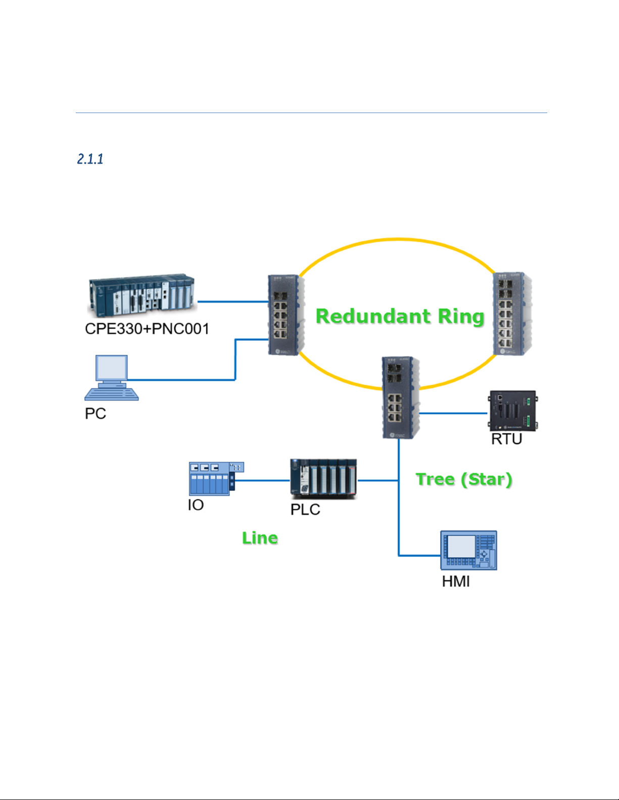
GLM Switches are treated as PROFINET-IO devices. The host PLC will therefore use an embedded PROFINET
port or a PNC001 PROFINET IO-Controller Module. All physical connections use standard Ethernet connectors
(RJ45 or SFP).
Figure 4: Typical PROFINET System with GLM Switches
Page 11

Chapter 2. Overview
4 PACSystems PROFINET Managed Industrial Ethernet Switches User Manual GFK-3030
Ethernet Devices on an Ethernet Network
The GLM switches contain a number of features which cannot be accessed over PROFINET, but are available
over Ethernet. The user may choose to install a separate Ethernet network for this purpose, or run both
PROFINET and Ethernet on the same physical network. Refer to Appendix B, Supported Ethernet Commands.
Caution
Care needs to be taken that connection to an Ethernet networks does not expose
the application to outside interference or monitoring, and does not impose heavy
traffic on the PROFINET network, which is intended to service IO-Devices in a timely
manner. Refer to the PACSystems RXi, RX3i, RX7i and RSTi-EP Controller Secure
Deployment Guide, GFK-2830.
Within the RX3i, the user may install an ETM001 module in a rack controlled by the host PLC CPU, or may use
an embedded Ethernet port within the CPU itself to provide the Ethernet features. .If none of the Ethernet-only
features will be used, no dedicated Ethernet function is required.
The following features, which are outside the scope of this manual, may be accessed over Ethernet, but may
not be accessed over PROFINET:
• Virtual LANs (VLANs)
• Access Control List Security (ACL)
• Quality of Service (QoS) features
• Internet Group Management Protocol (IGMP)
GLM System Capabilities
Function Name
System Max Value
VLAN ID
4096
VLAN Limitation
1024
Privilege Level of User
15
RMON Statistic Entry
65535
RMON Alarm Entry
65
RMON Event Entry
65535
IPMC Profile
64
IPMC Rule / Address Entry
128
ACE
256
ICMP Type / Code
255
MAC-based VLAN Entry
256
IP subnet-based VLAN Entry
128
Protocol-based VLAN Group
125
Voice VLAN OUI
16
QCE
256
IP Interface (for management)
8
IP Route (for management)
32
Security Access Management
16
MVR VLAN
4
MAC Learning table address
8k
IGMP Group
256
Page 12
Chapter 2. Overview
GFK-3030 December 2017 5
2.2 GLM Product Differentiation
Product differentiation within the GLM Series of products lies in the number of standard RJ45 Ethernet
connections and Small Form-Factor Pluggable (SFP) ports offered, as follows:
Product
Number of RJ45 Ports
Number of SFP Ports
Appearance
IC086GLM064 6 4
Figure 1
IC086GLM082 8 2
Figure 2
IC086GLM104
10
4
Figure 3
Note that the final three digits of the GLM part numbers convey the information about the intrinsic port
configuration.
2.3 GLM Features
Each is a stand-alone Ethernet switch that may be mounted on a DIN-rail, or panel-mounted. Refer to Section
3.1.
Operating Temperature Range: -40°C to +75°C (-40°F to +167°F).
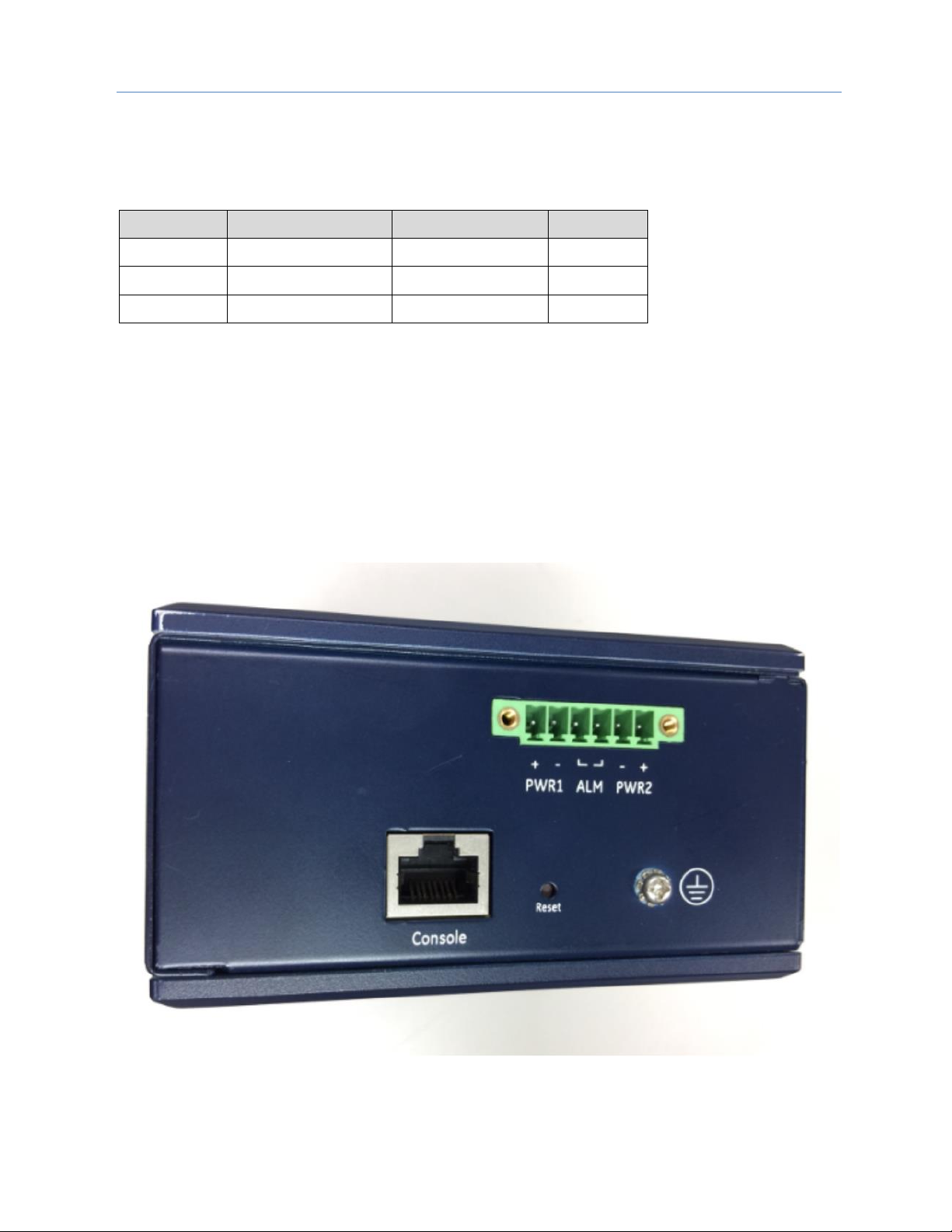
Each is equipped with the same bottom-panel (Figure 5), which includes a dual 12Vdc-58Vdc power input, a
ground stud, an alarm contact, a reset pushbutton and an RJ45 port suitable for attaching a console. Each of
these features is discussed in Chapter 3.
Figure 5: GLM Switch Bottom Panel
Page 13
Chapter 2. Overview
6 PACSystems PROFINET Managed Industrial Ethernet Switches User Manual GFK-3030
2.4 GLM LEDS
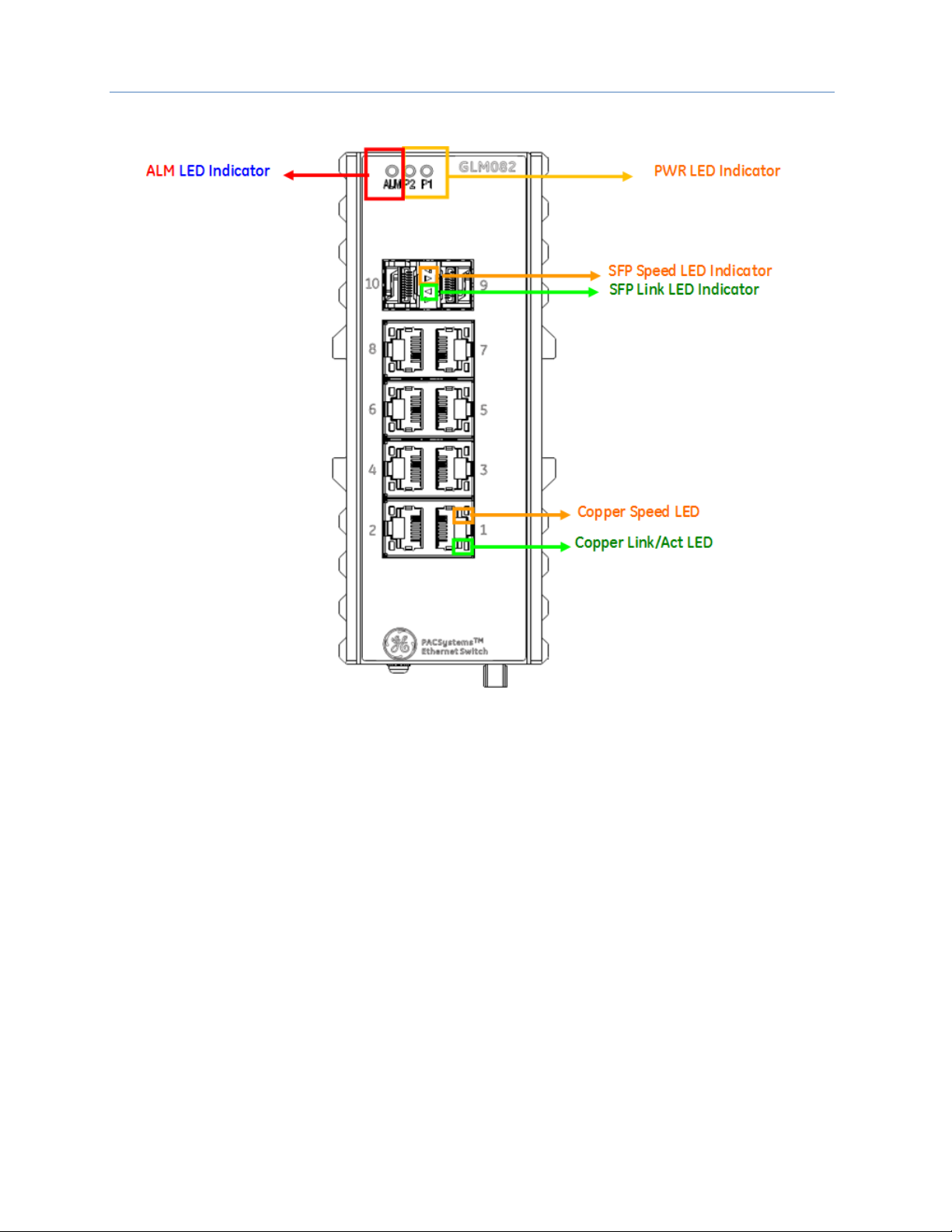
Figure 6: Front-Panel LEDs
Each GLM Switch product is equipped with a common set of LEDs, as shown in Figure 6:
• One LED for each of the two permitted power supply inputs (P1 and P2)
• One LED for the Alarm Contact (ALM)
For each Ethernet port, there is an amber speed LED and a green Link Activity LED. The appearance is different
for the RJ45 ports (suitable for copper cables) versus the SFP connectors, as indicated in Figure 6.
LED Operation is detailed in Section 3.6.
Page 14
GFK-3030 December 2017 7
Chapter 3 Installation
3.1 Mounting
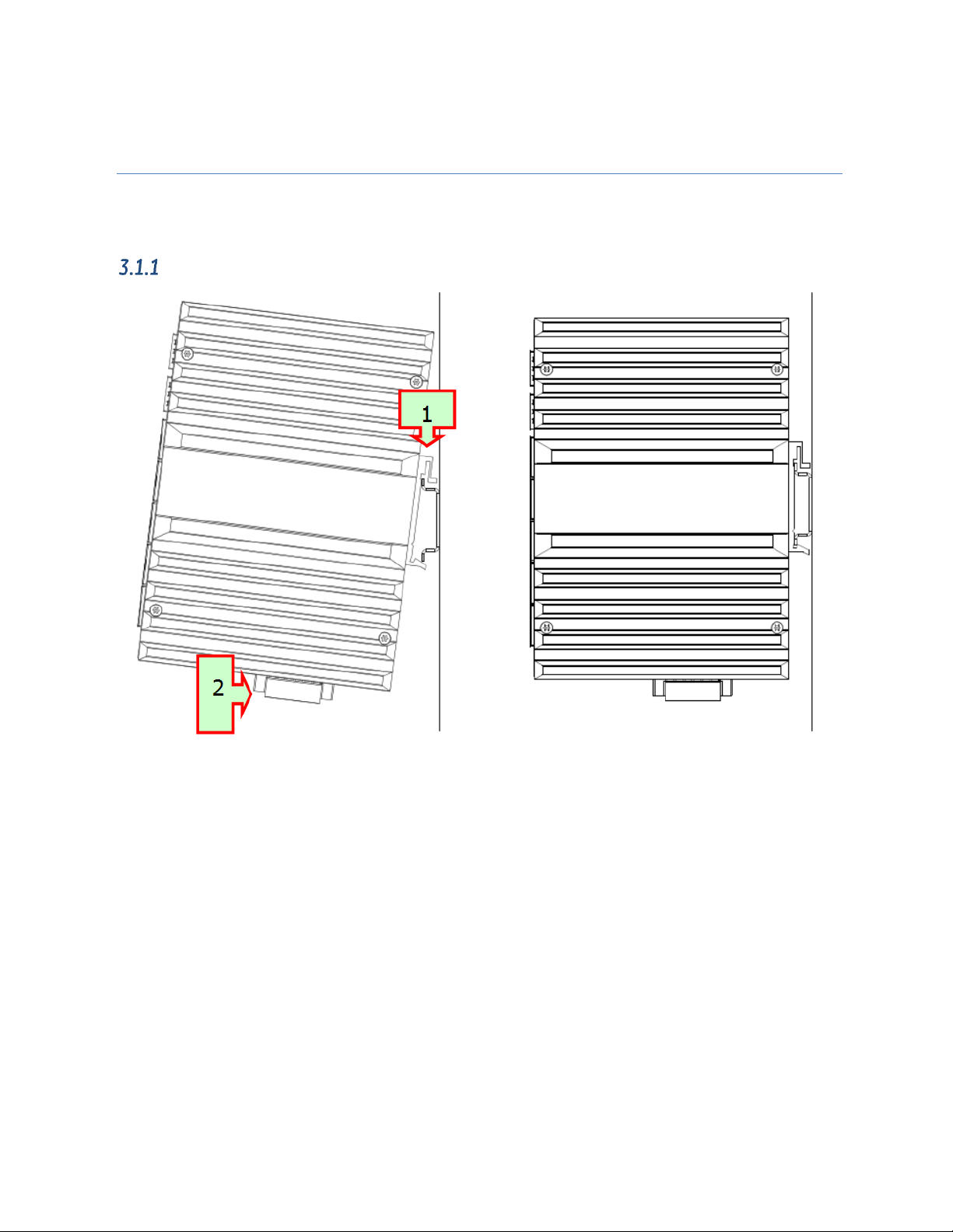
The GLM switches may be DIN-rail mounted or panel-mounted.
DIN-Rail Mounting
Figure 7: DIN-Rail Mounting
1) Attach the DIN-Rail bracket to the mounting surface with the bracket and screws in the included
accessory kit.
2) Hook the top edge of the DIN-Rail latch attached to the GLM switch over the top edge of the DIN rail.
3) Push the bottom of the GLM unit towards the DIN Rail until the bottom latch snaps into place.
Page 15
Chapter 3. Installation
8 PACSystems PROFINET Managed Industrial Ethernet Switches User Manual GFK-3030
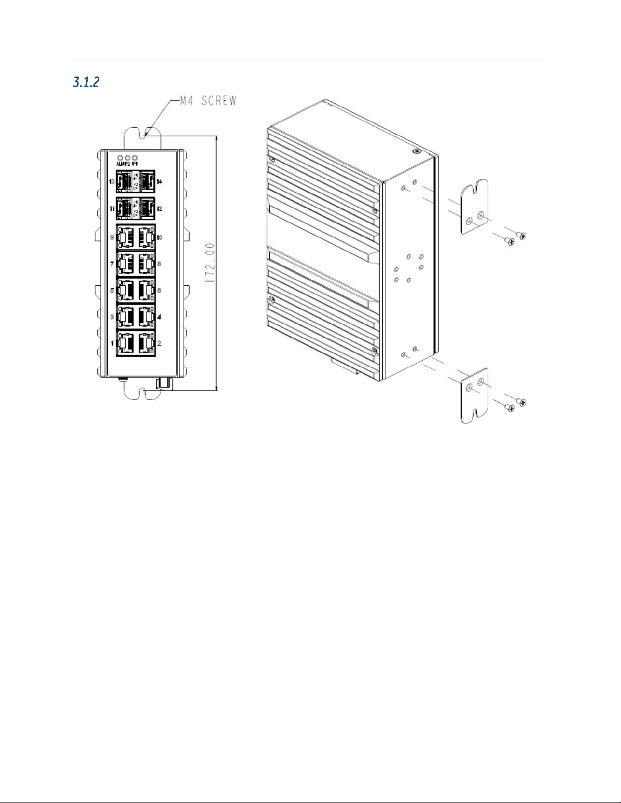
Panel Mounting
Figure 8: Panel-Mounting
1) Prepare two pilot holes in the mounting surface 172mm apart, per Figure 8.
2) Attach the top and bottom panel-mounting plates to the rear of the GLM switch chassis using the
screws provided in the accessory kit.
3) Secure the GLM switch to the mounting surface with a pair of M4 machine screws.
Page 16
Chapter 3. Installation
GFK-3030 December 2017 9
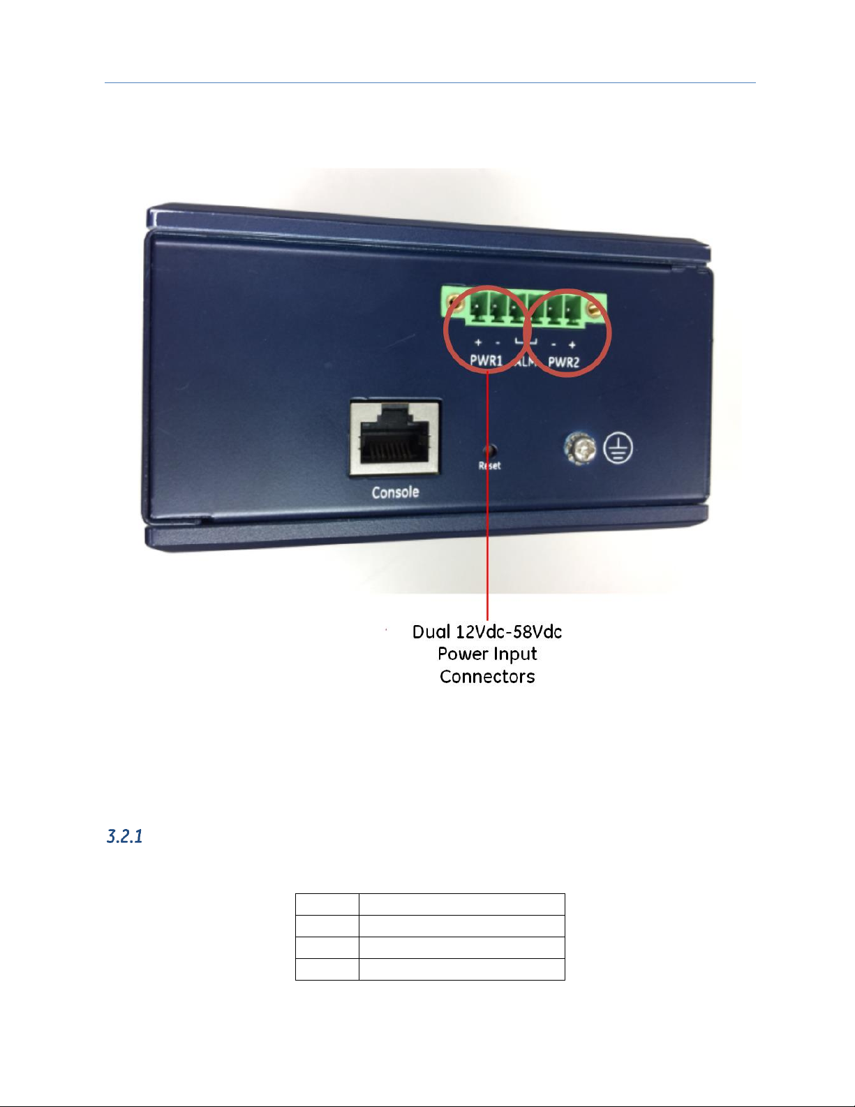
3.2 Power Connection
The 6-pin terminal block on the bottom panel contains connectors for two DC power inputs. Each is indicated
with polarity signs, as shown.
Figure 9: Dual DC Power Input Connections
The GLM Switch may be powered from one or both power inputs. The specified voltage range is 12Vdc–58Vdc.
The 6-pin terminal strip will accept AWG 28~14. The wire should be stripped back 6~7mm. The screw torque
limit is 2Nm.
The P1 and P2 LEDs on the front panel indicate the status of these two power supply inputs, as shown in
Section 3.6, LED Operation.
GLM Switch Current Draw
The maximum current draw at 24Vdc (nominal) for each of the devices is shown below:
Device
Max Current @ 24Vdc (nominal)
GLM064
580mA
GLM082
521mA
GLM104
709mA
Note: Each DC power input should be connected to a suitably-fused power supply.
Page 17
Chapter 3. Installation
10 PACSystems PROFINET Managed Industrial Ethernet Switches User Manual GFK-3030
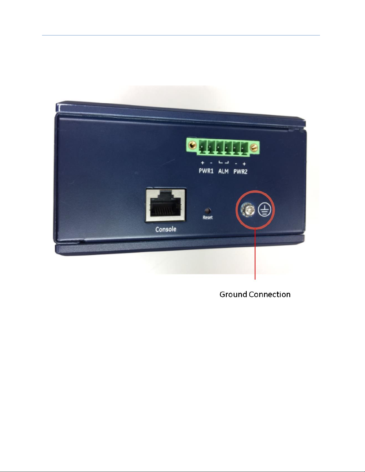
3.3 Grounding
Each GLM switch must be properly grounded for optimal performance. A ground screw (chassis ground) is
provided as part of the bottom panel, as shown below. Loosen the ground screw, insert the stripped end of the
ground strap, then tighten the ground screw to secure the ground strap in place. The other end of the ground
strap (which should be as short as possible) should be securely connected to earth ground.
Figure 10: Ground Connection
Page 18
Chapter 3. Installation
GFK-3030 December 2017 11
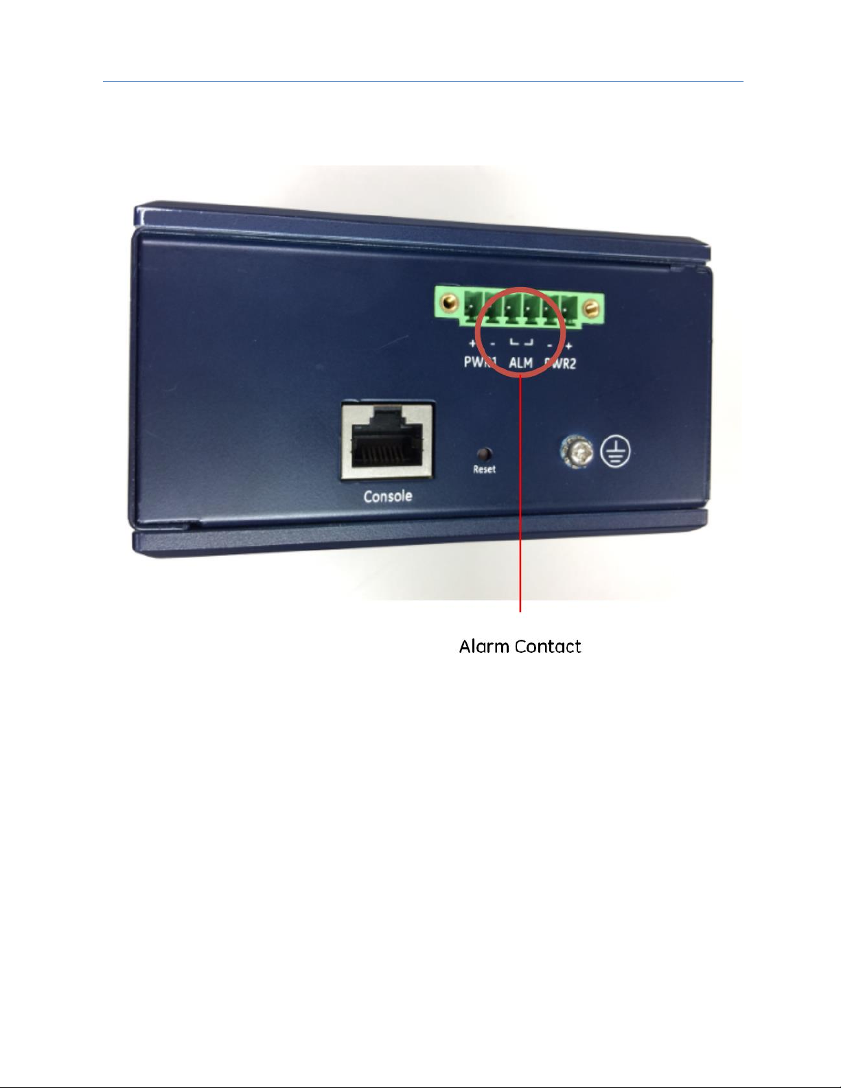
3.4 Alarm Relay Output
The Alarm Relay Output is located on the two terminals in the center of the 6-pin terminal strip on the bottom
panel.
Figure 11: Alarm Relay Output
The Alarm Relay Output may be connected to an external device. It is a Normally Open Relay. The state of the
Alarm Relay is indicated on the ALM LED, as documented in Section 3.6, LED Operation.
Refer to Section 3.2 for wire size and stripping information.
Figure 38 diagrams a typical external alarm circuit.
Page 19
Chapter 3. Installation
12 PACSystems PROFINET Managed Industrial Ethernet Switches User Manual GFK-3030
3.5 Ethernet Connections
Ethernet connections use either RJ45 (electrical) or mini-GBIC (optical) interfaces. All Ethernet connections are
located on the faceplate. Refer to Figure 1 through Figure 3.The number and type available for each product in
the GLM series is discussed in Section 2.1.3, GLM System Capabilities.
The activity and speed of each port is indicated separately, as documented in Section 3.6, LED Operation.
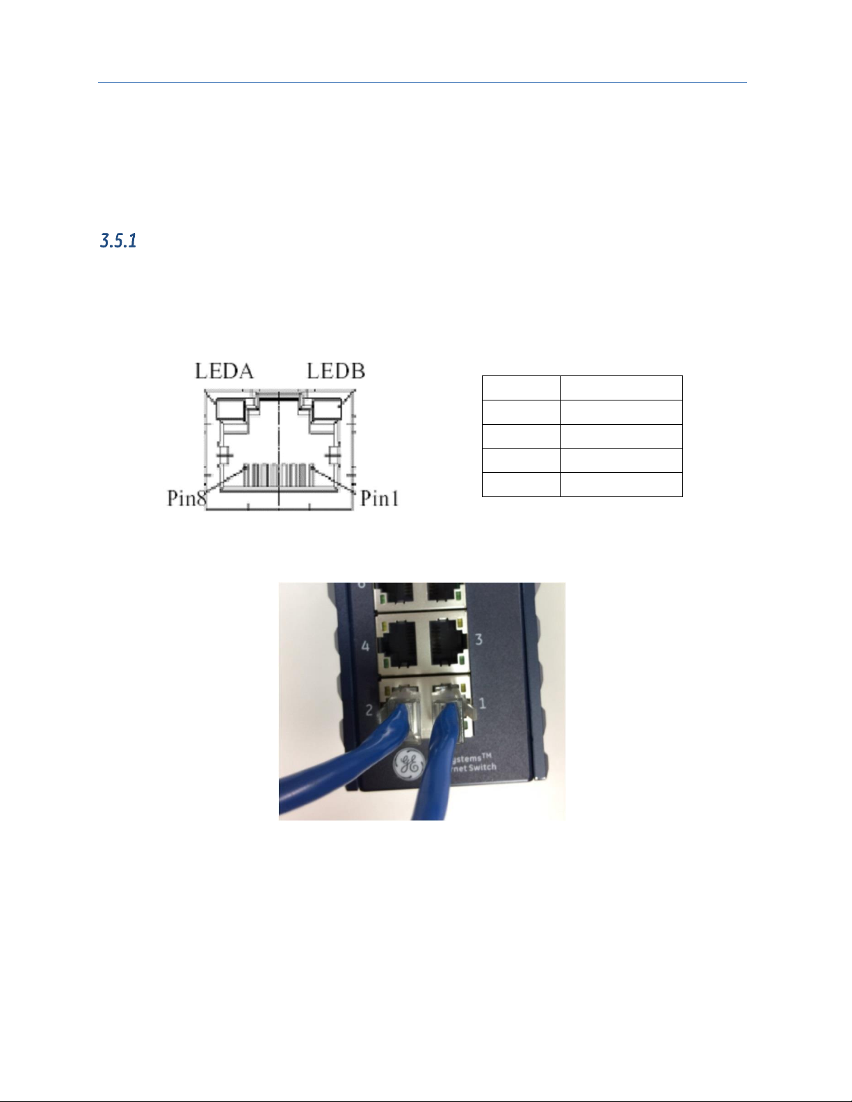
RJ45 Connections
GLM Switches use standard RJ45 connectors for their electrical interfaces. For example, on GLM082, Ports 1-8
are electrical only.
• To connect to a PC, use a straight-through or a cross-over Ethernet cable
• To connect the GLM Switch copper port to an Ethernet device, use UTP (Unshielded Twisted Pair) or
STP (Shielded Twisted Pair) Ethernet cables.
Figure 12: RJ45 Pinout
Pin
Assignment
1,2
T/Rx+, T/Rx-
3,6
T/Rx+, T/Rx-
4,5
T/Rx+, T/Rx-
7,8
T/Rx+, T/Rx-
Figure 13: Ports 1 & 2 Copper Connections
Page 20

Chapter 3. Installation
GFK-3030 December 2017 13
SFP Connections
GLM Switches provide SFP connections using an optical (mini-GBIC) interface. For example, on GLM082, Ports
9 and 10 are SFP ports.
Figure 14: Fiber-Optic Cable with LC Duplex Connectors
Figure 15: Attach Fiber-Optic Cables to Installed SFP
Socket
Prepare a suitable SFP module and install it into the GLM optical port. Then connect the fiber optic cabling that
uses LC connectors (or SC connectors with the use of an optional SC-to-LC adapter) to the fiber optic socket.
Warning
Never attempt to view optical connectors that might be emitting laser energy.
Do not power up the laser product without first connecting the laser to the optical
fiber and properly installing the protective cover.
Laser light, which may cause damage to the eye, will be produced as soon as
power is applied to the laser source.
Warning
When a fiber optic connector is removed during installation, testing, or servicing, or
when an energized fiber is broken, there is a risk of injury to the eye. Exposure to
optical energy may be hazardous to the eye, depending on the laser output power.
The primary hazards of exposure to laser radiation from an optical-fiber
communication system are:
Damage to the eye by accidental exposure to a beam emitted by a laser
source.
Damage to the eye from viewing a connector attached to a broken fiber or an
energized fiber.
Page 21

Chapter 3. Installation
14 PACSystems PROFINET Managed Industrial Ethernet Switches User Manual GFK-3030
3.6 LED Operation
LED
STATE
Description
P1
On Green
P1 input power is within specification
Off
P1 power line is disconnected or
supply power is not within specifications
P2
On Green
P2 input power is within specification
Off
P2 power line is disconnected or
supply power is not within specifications
Alarm
On Red
Alarm contact energized
Off
Alarm contact not energized
Copper ports Link/Act
On Green
Ethernet link up but no traffic is detected
Flashing Green
Ethernet link up and there is traffic detected
Off
Ethernet link down
Copper ports Speed
On Yellow
A 100 Mbps or a 1000Mbps connection is detected
Off
No link or a 10 Mbps connection is detected
SFP port Link/Act
On Green
Ethernet link up
Off
Ethernet link down
SFP port Speed
On Yellow
SFP port speed 1000Mbps connection is detected.
Off
No link or a SFP port speed 100Mbps connection is detected
Page 22
Chapter 3. Installation
GFK-3030 December 2017 15
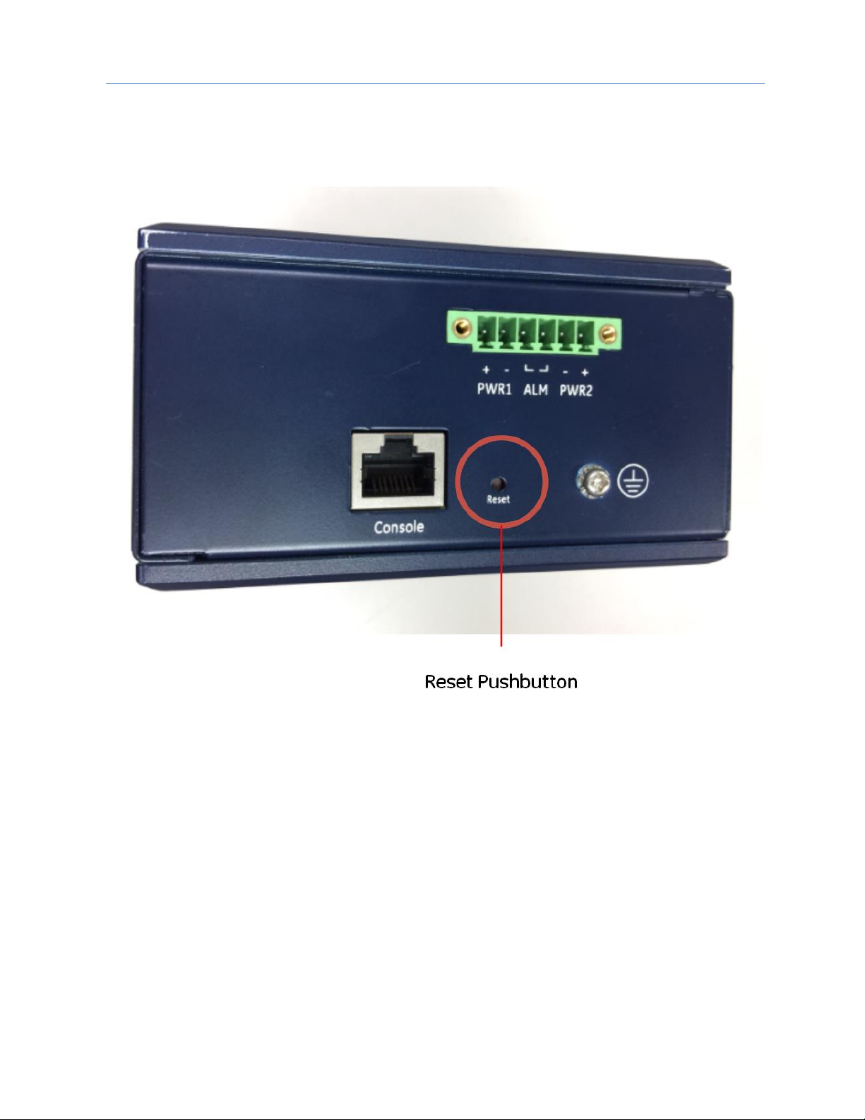
3.7 System Reset
In the event a GLM switch becomes unresponsive, press the recessed Reset button located on the bottom
panel. The reset pushbutton reboots the GLM switch without the need to remove power from that switch.
Resetting a switch is normally not required. The Reset button is recessed in order to avoid accidental use.
Page 23
Chapter 3. Installation
16 PACSystems PROFINET Managed Industrial Ethernet Switches User Manual GFK-3030
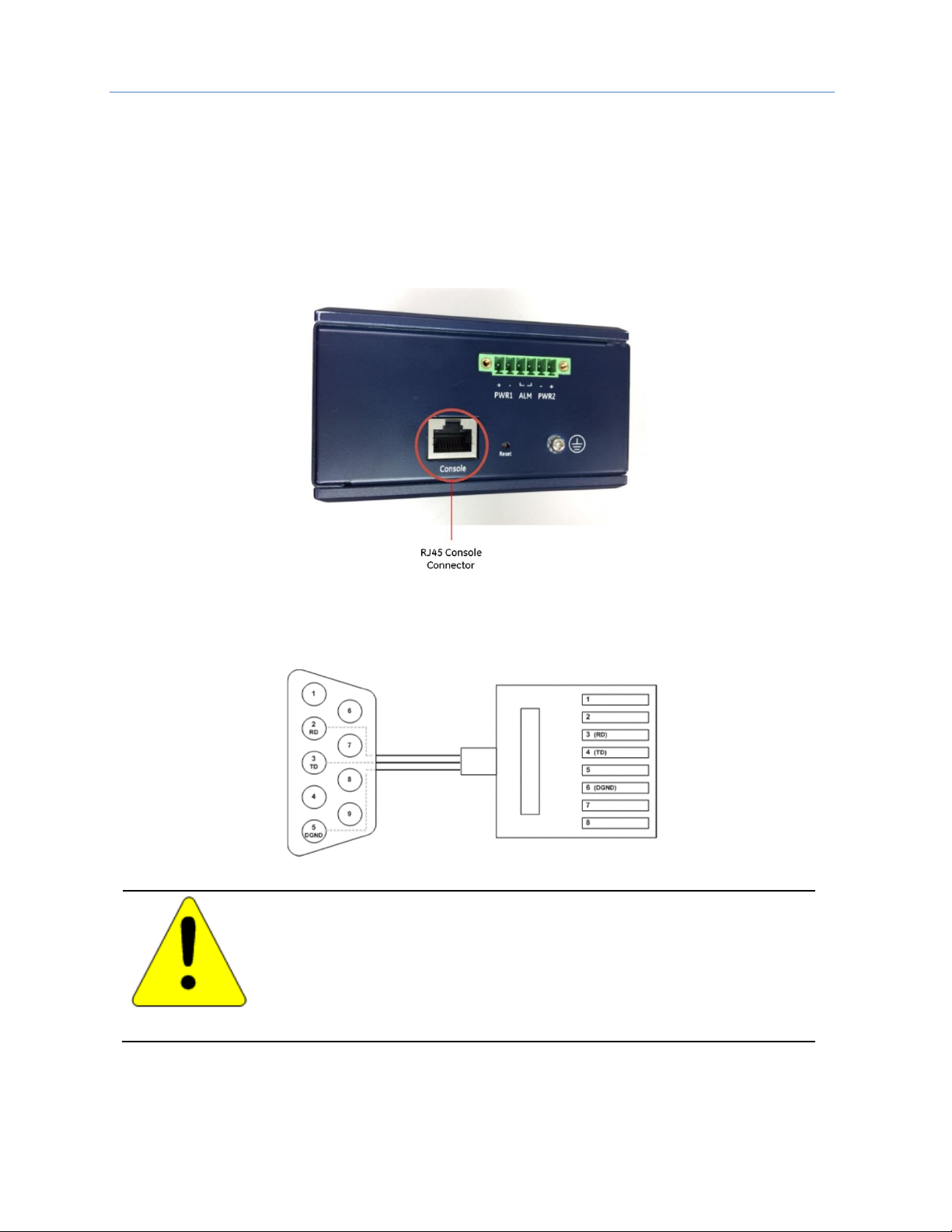
3.8 Console Connection
The Console port, located on the bottom panel (Figure 16), is intended for administrative functions, and its use
is optional. It uses a terminal emulator or a computer with terminal emulation software, connected as follows:
• DB9 connector connected to computer COM port
• Baud rate: 115,200bps
• 8 data bits, 1 stop bit
• No parity
• No flow control
Figure 16: Console Port
To connect the host PC to the Console port, an RJ45 (male) connector-to-RS232 DB9 (female) connector cable
is required. The RJ45 connector of the cable is connected to the Console port of GLM Series; the DB9
connector of the cable is connected to the PC COM port. The wiring for this cable is shown in Figure 17.
Figure 17: Console Cable Wiring
Caution
Console connections should not be permanent. Once any administrative functions
have been performed, disconnect the PC used for that purpose. Leaving a
computer connected would expose the application to security risks. Refer to the
PACSystems RXi, RX3i, RX7i and RSTi-EP Controller Secure Deployment Guide,
GFK-2830.
Refer to Appendix A, Command Language Interface (CLI), for related commands and syntax.
Page 24

GFK-3030 December 2017 17
Chapter 4 Configuration
Configuration is accomplished using Proficy Machine Edition (PME). Each GLM device has a corresponding
GSDML file, which must also be imported.
The GLM Switch Device is always used as a PROFINET IO-Device. Select a suitable PROFINET Controller within
the CPU and “add” a new IO- Device to the corresponding PROFINET Network. The PROFINET Controller may be
an embedded PROFINET Controller Port in the CPU, or a PROFINET Controller module located in a rack
controlled by a CPU. Refer to the corresponding CPU manual for instructions on how to set up an embedded
PROFINET Controller LAN. Refer also to the PACSystems RX3i & RSTi-EP PROFINET I/O Controller Manual,
GFK-2571, which covers further details on embedded PROFINET Controllers and on setting up a PNC001
PROFINET Controller module.
If the GLM Switch Device is to be used as an Ethernet Device, select a suitable Ethernet Controller within the
CPU and “add” a new IO- Device to the corresponding Ethernet Network. The controlling Ethernet Device may
be an embedded Ethernet Port in the CPU, or an Ethernet module located in a rack controlled by a CPU. Refer
to the corresponding CPU manual for instructions on how to set up an embedded Ethernet LAN. Refer to the
PACSystems RX3i Ethernet Network Interface Unit User’s Manual, GFK-2349, for instructions on locating an
ETM001 in a suitable rack/slot location, then setting up its Ethernet LANs and adding devices to those LANs.
Page 25
Chapter 4. Configuration
18 PACSystems PROFINET Managed Industrial Ethernet Switches User Manual GFK-3030
4.1 Import the GSDML file
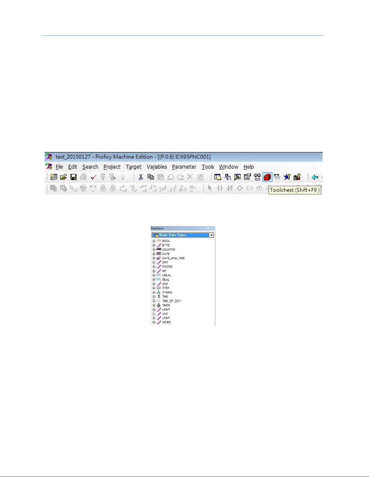
Browse to the folder containing the GSDML file, then import it using the Toolchest feature of PME, as shown
below. Alternately, use the Have GSDML button shown in Figure 25, and perform the import as configuration
progresses.
Each GLM Switch Catalog Number has a unique GSDML file associated with it.
Note that you will only need to import any given GSDML file once. The file can then be used to define the
parameters associated with each GLM switch of the corresponding type added to the network.
If a newer version of a GSDML file becomes available, it will reside in the Toolchest alongside older versions.
The user has the option to change the version of the GSDML file associated with each installed GLM Switch
device.
If all GLM switches have been associated with a newer version of the GSDLM file, and the older version of the
GSDML file is no longer required, it can be deleted from the Toolchest.
Figure 18: PME Toolchest Feature
The Toolchest offers a drop-down list of various data types:
Figure 19: Toolchest Data Types
Page 26

Chapter 4. Configuration
GFK-3030 December 2017 19
Since the GLM Switch is to be used as a PROFINET Device, select PROFINET Devices from the drop-down list
(Figure 20).
Figure 20: Select PROFINET Device
Right click on the PROFINET Devices line item. At the bottom of the resulting drop-down menu, under
Assistants, select the Import GSDML command.
Figure 21: Import GSDML Command
Page 27
Chapter 4. Configuration
20 PACSystems PROFINET Managed Industrial Ethernet Switches User Manual GFK-3030
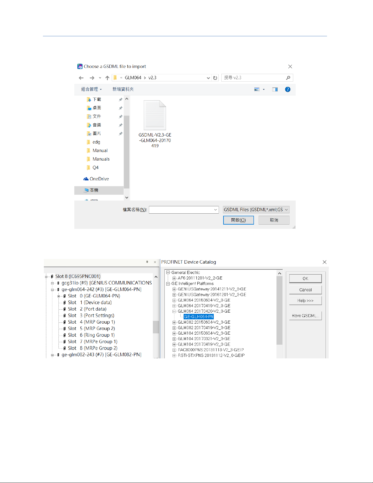
The resulting dialog box allows you to browse to the desired folder and select the GSDML file.
Figure 22: Browse to Folder and Select GSDML file for Import
The Toolchest now displays the newly-added device:
Figure 23: Toolchest Displays Newly-Added Device
Page 28

Chapter 4. Configuration
GFK-3030 December 2017 21
4.2 Associating the IO-Device with its Controller
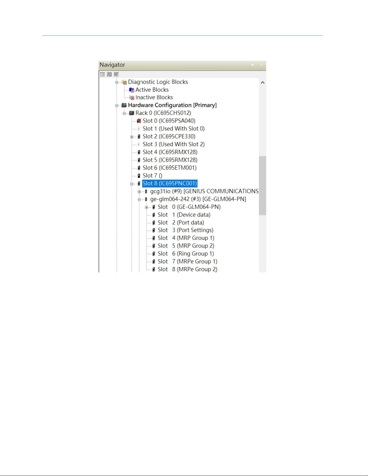
Each GLM Switch device has to be associated with the PROFINET Controller which will be controlling and
monitoring it. Figure 24 shows that the PNC001 module located in Slot 6 of Rack 0 (the Main CPU Rack) has
been selected. Then with right-click, the menu item Add IO-Device has been selected.
Figure 24: Add IO-Device to PROFINET Controller
Since the device being added is associated with a PROFINET-IO Controller, it will be selected from the catalog
of available PROFINET Devices (upper left portion of Figure 25):
Figure 25: Select IO-Device from PROFINET Device Catalog
Use the Have GSDML button in Figure 25 to select the GSDML file associated with the previously selected GLM
catalog number. This interface allows you to browse to the folder in which the GSDML file is located, and select
the appropriate file. In Figure 25, expand the tree using the “+” icons and select the IO-Device from the catalog
list.
Page 29
Chapter 4. Configuration
22 PACSystems PROFINET Managed Industrial Ethernet Switches User Manual GFK-3030
Once selected, the IO-Device will display as having been installed under the previously selected PNC001.
Figure 26: IO-Device Installed Under PNC001
Also note that the constituent ports of the new IO-Device are also displayed in Figure 26.
The data from the associated slots (shown in Figure 26) is treated as Cyclic I/O Data (RTC) by the PROFINET
Controller.
Page 30

Chapter 4. Configuration
GFK-3030 December 2017 23
4.3 PROFINET Cyclic I/O Data
Cyclic I/O Data is that data obtained by the PROFINET Controller from each PROFINET IO-Device in a cyclic
manner. The default transfer frequency of PROFINET cyclic data is 128ms. The GSDML file supports three
possible values: 128ms, 256ms and 512ms.
PME is used to assign base references to the Cyclic I/O Data of each GLM IO-Device. Each slot of the GLM
IO-Device has a Settings form, such as that shown in Figure 27. Double-click on the slot to bring up the
corresponding form.
• If the Slot has Output values (as defined by the Direction column in the following tables), it will require
a base reference in %Q. The lowest order bit in the Output table will correspond to the selected %Q
reference value, which must be a multiple of 8, plus 1.
• If the Slot has Input values (as defined by the Direction column in the following tables), it will require a
base reference in %I. The lowest order bit in the Input table will correspond to the selected %I
reference value, which must be a multiple of 8, plus 1.
In the case of slot 3, where there are matching input and output settings, GE recommends selecting the same
%I and %Q references, as this will avoid confusion when debugging and in project documentation. For
instance, if %I00129 is used for the Port Alarm Inputs, then use %Q00129 for the Port Alarm Outputs. Also note
that 16 contiguous %I and %Q references are required to accommodate all the Port Alarm flags (in both %I
and in %Q). Finally, do not allow any other devices or device slots to overlap the selected %I and %Q settings.
If PME is allowed to automatically assign the next available %I and %Q references, there will likely be no
alignment between the %I and %Q bits assigned to any given GLM IO-Device. This will work fine, but may
cause confusion when debugging.
Figure 27: Assign Starting %I & %Q References for Cyclic I/O Data
The constituent data content is documented in the following sections:
• Slot 1 (of the GLM Switch Device) contains Device Status.
• Slot 2 contains Port Status.
• Slot 3 contains Port Alarm Settings & Status.
• Slot 4 contains MRP Group 1 Status.
• Slot 5 contains MRP Group 2 Status.
• Slot 6 contains Ring Group 1 Status
• Slot 7 contains MRE Group 1 Status
• Slot 8 contains MRE Group 2 Status
The Status Flags are discussed in Chapter 5, Diagnostics.
Page 31

Chapter 4. Configuration
24 PACSystems PROFINET Managed Industrial Ethernet Switches User Manual GFK-3030
Slot 1: Device Status
Category
Direction
Byte#
Bit#
Name
Description
Device Data
(Slot 1)
Input
0
0
Alarm Status
0=No Alarm (ALM Relay Open),
1=Alarm Detected (ALM Relay Closed)
1
Power 1 Status
0=PWR1 not OK, 1=PWR1 OK
2
Power 2 Status
0=PWR2 not OK, 1=PWR2 OK
3
Ring Enabled/Disabled
0=Disabled, 1=Enabled
4
Ring Status
0=Failure, 1=Normal Condition
Slot 2: Port Status
Category
Direction
Byte#
Bit#
Name
Description
Port Status
(Slot 2)
Input
0
0
Port 1 Connection
0=Not Connected, 1=Connected
1
Port 2 Connection
0=Not Connected, 1=Connected
2
Port 3 Connection
0=Not Connected, 1=Connected
3
Port 4 Connection
0=Not Connected, 1=Connected
4
Port 5 Connection
0=Not Connected, 1=Connected
5
Port 6 Connection
0=Not Connected, 1=Connected
6
Port 7 Connection
0=Not Connected, 1=Connected
7
Port 8 Connection
0=Not Connected, 1=Connected
Input
1
0
Port 9 Connection
0=Not Connected, 1=Connected
1
Port 10 Connection
0=Not Connected, 1=Connected
2
Port 11 Connection1
0=Not Connected, 1=Connected
3
Port 12 Connection1
0=Not Connected, 1=Connected
4
Port 13 Connection1
0=Not Connected, 1=Connected
5
Port 14 Connection1
0=Not Connected, 1=Connected
6
Reserved
7
Reserved
1
GLM104 only
Page 32

Chapter 4. Configuration
GFK-3030 December 2017 25
Slot 3: Port Alarm & Port Settings & Status
Category
Direction
Byte#
Bit#
Name
Output
Description
Input Description
Port Settings
(Slot 3)
Input &
Output
0
0
Port 1 Alarm
0=Alarm Disabled,
1=Alarm Enabled
0=No Alarm
1=Alarm Condition Detected
1
Port 2 Alarm
0=Alarm Disabled,
1=Alarm Enabled
0=No Alarm
1=Alarm Condition Detected
2
Port 3 Alarm
0=Alarm Disabled,
1=Alarm Enabled
0=No Alarm
1=Alarm Condition Detected
3
Port 4 Alarm
0=Alarm Disabled,
1=Alarm Enabled
0=No Alarm
1=Alarm Condition Detected
4
Port 5 Alarm
0=Alarm Disabled,
1=Alarm Enabled
0=No Alarm
1=Alarm Condition Detected
5
Port 6 Alarm
0=Alarm Disabled,
1=Alarm Enabled
0=No Alarm
1=Alarm Condition Detected
6
Port 7 Alarm
0=Alarm Disabled,
1=Alarm Enabled
0=No Alarm
1=Alarm Condition Detected
7
Port 8 Alarm
0=Alarm Disabled,
1=Alarm Enabled
0=No Alarm
1=Alarm Condition Detected
2
0
Port 9 Alarm
0=Alarm Disabled,
1=Alarm Enabled
0=No Alarm
1=Alarm Condition Detected
1
Port 10 Alarm
0=Alarm Disabled,
1=Alarm Enabled
0=No Alarm
1=Alarm Condition Detected
2
Port 11 Alarm1
0=Alarm Disabled,
1=Alarm Enabled
0=No Alarm
1=Alarm Condition Detected
3
Port 12 Alarm1
0=Alarm Disabled,
1=Alarm Enabled
0=No Alarm
1=Alarm Condition Detected
4
Port 13 Alarm1
0=Alarm Disabled,
1=Alarm Enabled
0=No Alarm
1=Alarm Condition Detected
5
Port 14 Alarm1
0=Alarm Disabled,
1=Alarm Enabled
0=No Alarm
1=Alarm Condition Detected
6
Reserved
7
Reserved
Note: Bytes 0 and 2 are not contiguous (see next page).
Page 33

Chapter 4. Configuration
26 PACSystems PROFINET Managed Industrial Ethernet Switches User Manual GFK-3030
Category
Direction
Byte#
Bit#
Name
Output Description
Input Description
Port Settings
(Slot 3)
(continued)
Input &
Output
1
0
Port 1 Admin
0=Enable Port,
1=Disable Port
0=Port Enabled
1=Port Disabled
1
Port 2 Admin
0=Enable Port,
1=Disable Port
0=Port Enabled
1=Port Disabled
2
Port 3 Admin
0=Enable Port,
1=Disable Port
0=Port Enabled
1=Port Disabled
3
Port 4 Admin
0=Enable Port,
1=Disable Port
0=Port Enabled
1=Port Disabled
4
Port 5 Admin
0=Enable Port,
1=Disable Port
0=Port Enabled
1=Port Disabled
5
Port 6 Admin
0=Enable Port,
1=Disable Port
0=Port Enabled
1=Port Disabled
6
Port 7 Admin
0=Enable Port,
1=Disable Port
0=Port Enabled
1=Port Disabled
7
Port 8 Admin
0=Enable Port,
1=Disable Port
0=Port Enabled
1=Port Disabled
3
0
Port 9 Admin
0=Enable Port,
1=Disable Port
0=Port Enabled
1=Port Disabled
1
Port 10 Admin
0=Enable Port,
1=Disable Port
0=Port Enabled
1=Port Disabled
2
Port 11 Admin1
0=Enable Port,
1=Disable Port
0=Port Enabled
1=Port Disabled
3
Port 12 Admin1
0=Enable Port,
1=Disable Port
0=Port Enabled
1=Port Disabled
4
Port 13 Admin1
0=Enable Port,
1=Disable Port
0=Port Enabled
1=Port Disabled
5
Port 14 Admin1
0=Enable Port,
1=Disable Port
0=Port Enabled
1=Port Disabled
6
Reserved
7
Reserved
Note: Bytes 1 and 3 are not contiguous (see previous page).
Page 34

Chapter 4. Configuration
GFK-3030 December 2017 27
Slot 4: MRP Group 1 Status
Category
Direction
Byte#
Bit#
Name
Description
MRP Group 1
(Slot 4)
Input
0
0
MRP Group 1 Mode
0=MRP Disabled, 1=MRP Enabled
1
MRP Group 1 Role
0=MRP Client, 1=MRP Master
MRP Group 1
Ports
(Slot 4)
Input
1
0
Port 1 MRP-G1 Status
0=Not MRP-G1 Ring Port
1=MRP-G1 Ring Port
1
Port 2 MRP-G1 Status
0=Not MRP-G1 Ring Port
1=MRP-G1 Ring Port
2
Port 3 MRP-G1 Status
0=Not MRP-G1 Ring Port
1=MRP-G1 Ring Port
3
Port 4 MRP-G1 Status
0=Not MRP-G1 Ring Port
1=MRP-G1 Ring Port
4
Port 5 MRP-G1 Status
0=Not MRP-G1 Ring Port
1=MRP-G1 Ring Port
5
Port 6 MRP-G1 Status
0=Not MRP-G1 Ring Port
1=MRP-G1 Ring Port
6
Port 7 MRP-G1 Status
0=Not MRP-G1 Ring Port
1=MRP-G1 Ring Port
7
Port 8 MRP-G1 Status
0=Not MRP-G1 Ring Port
1=MRP-G1 Ring Port
2
0
Port 9 MRP-G1 Status
0=Not MRP-G1 Ring Port
1=MRP-G1 Ring Port
1
Port 10 MRP-G1 Status
0=Not MRP-G1 Ring Port
1=MRP-G1 Ring Port
2
Port 11 MRP-G1 Status1
0=Not MRP-G1 Ring Port
1=MRP-G1 Ring Port
3
Port 12 MRP-G1 Status1
0=Not MRP-G1 Ring Port
1=MRP-G1 Ring Port
4
Port 13 MRP-G1 Status1
0=Not MRP-G1 Ring Port
1=MRP-G1 Ring Port
5
Port 14 MRP-G1 Status1
0=Not MRP-G1 Ring Port
1=MRP-G1 Ring Port
6
Reserved
7
Reserved
Page 35

Chapter 4. Configuration
28 PACSystems PROFINET Managed Industrial Ethernet Switches User Manual GFK-3030
Slot 5: MRP Group 2 Status
Category
Direction
Byte#
Bit#
Name
Description
MRP Group 2
(Slot 5)
Input
0
0
MRP Group 2 Mode
0=MRP Disabled, 1=MRP Enabled
1
MRP Group 2 Role
0=MRP Client, 1=MRP Master
MRP Group 2
Ports
(Slot 5)
Input
1
0
Port 1 MRP-G2 Status
0=Not MRP-G2 Ring Port
1=MRP-G2 Ring Port
1
Port 2 MRP-G2 Status
0=Not MRP-G2 Ring Port
1=MRP-G2 Ring Port
2
Port 3 MRP-G2 Status
0=Not MRP-G2 Ring Port
1=MRP-G2 Ring Port
3
Port 4 MRP-G2 Status
0=Not MRP-G2 Ring Port
1=MRP-G2 Ring Port
4
Port 5 MRP-G2 Status
0=Not MRP-G2 Ring Port
1=MRP-G2 Ring Port
5
Port 6 MRP-G2 Status
0=Not MRP-G2 Ring Port
1=MRP-G2 Ring Port
6
Port 7 MRP-G2 Status
0=Not MRP-G2 Ring Port
1=MRP-G2 Ring Port
7
Port 8 MRP-G2 Status
0=Not MRP-G2 Ring Port
1=MRP-G2 Ring Port
2
0
Port 9 MRP-G2 Status
0=Not MRP-G2 Ring Port
1=MRP-G2 Ring Port
1
Port 10 MRP-G2 Status
0=Not MRP-G2 Ring Port
1=MRP-G2 Ring Port
2
Port 11 MRP-G2 Status1
0=Not MRP-G2 Ring Port
1=MRP-G2 Ring Port
3
Port 12 MRP-G2 Status1
0=Not MRP-G2 Ring Port
1=MRP-G2 Ring Port
4
Port 13 MRP-G2 Status1
0=Not MRP-G2 Ring Port
1=MRP-G2 Ring Port
5
Port 14 MRP-G2 Status1
0=Not MRP-G2 Ring Port
1=MRP-G2 Ring Port
6
Reserved
7
Reserved
Page 36

Chapter 4. Configuration
GFK-3030 December 2017 29
Slot 6: Ring Group 1 Status
Category
Direction
Byte#
Bit#
Name
Description
Ring Group 1
(Slot 6)
Input
0
0
Ring Group 1 Mode
0=Ring Disabled, 1=Ring Enabled
1
Ring Group 1 Role
0=Ring Slave, 1=Ring Master
2
Ring Status
0=Failure, 1=Normal Condition
Ring Group 1
Ports
(Slot 6)
Input
1
0…3
Ring Port 1 Number
Port ID number (1 thru 14)
4…6
Reserved
7 Port 1 Status
0=Forwarded, 1=Blocked
2
0…3
Ring Port 2 Number
Port ID number (1 thru 14)
4…6
Reserved
7
Port 2 Status
0=Forwarded, 1=Blocked
Slot 7: MRE Group 1 Status
Category
Direction
Byte#
Bit#
Name
Description
MRE Group 1
(Slot 7)
Input
0
0
MRE Group 1 Mode
0=Ring Disabled, 1=Ring Enabled
1
MRE Group 1 Role
0=Ring Slave, 1=Ring Master
2
Ring Status
0=Failure, 1=Normal Condition
1
0…3
Ring Port Number
Port ID number (1 thru 14)
4…6
Reserved
7
Port Status
0=Forwarded, 1=Blocked
Slot 8: MRE Group 2 Status
Category
Direction
Byte#
Bit#
Name
Description
MRE Group 2
(Slot 8)
Input
0
0
MRE Group 2 Mode
0=Ring Disabled, 1=Ring Enabled
1
MRE Group 2 Role
0=Ring Slave, 1=Ring Master
2
Ring Status
0=Failure, 1=Normal Condition
1
0…3
Ring Port Number
Port ID number (1 thru 14)
4…6
Reserved
7
Port Status
0=Forwarded, 1=Blocked
Page 37

Chapter 4. Configuration
30 PACSystems PROFINET Managed Industrial Ethernet Switches User Manual GFK-3030
4.4 PROFINET Acyclic I/O Data
The GLM Switches also support PROFINET Acyclic I/O Data (RTA). Data of this type has been mapped to the
sub-slots as indicated in this section, and may be retrieved via the assigned %I references.
Acyclic Device Data –Subslot 0
Byte
Name
Access
Value
Description
0
Device Status
read-only
0
Not supported
1
Device OK
2
Device bootup failed
1
Alarm Status
read-only
0
Not supported
1
No Alarm
2
Alarm condition detected
2
Power 1 Status
read-only
0
Not supported
1
PWR1 Input OK
2
PWR1 Input not OK
3
Power 2 Status
read-only
0
Not supported
1
PWR2 Input OK
2
PWR2 Input not OK
4
Redundant Mode
read-only
0
MRP
1
RSTP/MSTP2
2
Ring/Coupling/Dual Homing/Chain/Balancing Chain2
3
Non-Redundant
5
Ring-1 Mode
(config value)
read-only
0
Not supported
1
Enabled
2
Disabled
6
Ring-1 Role
read-only
0
Not supported
1
Ring Master
2
Ring Slave
7
Ring-1 State
read-only
0
Not supported
1
Disabled
2
Normal
3
Failed
2
This feature is not supported by RX3i CPUs.
Page 38

Chapter 4. Configuration
GFK-3030 December 2017 31
Byte
Name
Access
Value
Description
8
Ring-2 Mode
(config value)
read-only
0
Not supported
1
Enabled
2
Disabled
9
Ring-2 Role
read-only
0
Not supported
1
Ring Master2
2
Ring Slave2
3
Coupling Primary2
4
Coupling Backup2
5
Dual Homing2
10
Ring-2 State
read-only
0
Not supported
1
Disabled
2
Normal
3
Failed
11
Ring-3 Mode
(config value)
read-only
0
Not supported
1
Enabled
2
Disabled
12
Ring-3 Role
read-only
0
Not supported
1
Chain Head 2
2
Chain Tail 2
3
Chain Member 2
4
Balancing Chain Terminal 12
5
Balancing Chain Terminal 22
6
Balancing Chain Central Block 2
7
Balancing Chain Member 2
13
Ring-3 State
read-only
0
Not supported
1
Disabled 2
2
Normal 2
3
Failed 2
Page 39

Chapter 4. Configuration
32 PACSystems PROFINET Managed Industrial Ethernet Switches User Manual GFK-3030
Acyclic Port Data – Subslot 1
Byte
Name
Access
Value
Output Description
Input Description
0
Port Alarm
read-write
0
Do not send alarm
No Port Alarm
1
Send alarm when port link down
Port Alarm Detected
1
Port Setting
State
read-write
0
Not supported
Not supported
1
Off
Off
2
On
On
2
Port Link State
read-only
0 Not supported
1 Link is up
2 Link is down
3
Port Speed
read-only
0 Unavailable (link down)
1 10 Mbps
2 100 Mbps
3 1 Gbps
4
Port Duplex
read-only
0 Unavailable (link down)
1 Half 2
Full
5
Port Autonegotiation
read-only
0 Unavailable (link down)
1 Off
2 On
Page 40

Chapter 4. Configuration
GFK-3030 December 2017 33
Acyclic MRP Group 1 Data – Subslot 2
Byte
Name
Access
Value
Output Description
Input Description
0
MRP Mode
read-write
0
Disable MRP
MRP Disabled
1
Enable MRP (Default)
MRP Enabled
1
MRP Role
read-write
0
MRC (Default)
MRC
1
MRM
MRM
2
Ring Port1 of MRP
read-write
0~7
Assigned Port ID of Ring Port1
(0 corresponds to Port 1,
7 corresponds to Port 8)
0 is default value.
Port ID
3
Ring Port2 of MRP
read-write
0~7
Assigned Port ID of Ring Port 2
(0 corresponds to Port 1,
7 corresponds to Port 8)
1 is default value.
Port ID
Acyclic MRP Group 2 Data – Subslot 3
Byte
Name
Access
Value
Output Description
Input Description
0
MRP Mode
read-write
0
Disable MRP (Default)
MRP Disabled
1
Enable MRP
MRP Enabled
1
MRP Role
read-write
0
MRC (Default)
MRC
1
MRM
MRM
2
Ring Port1 of MRP
read-write
0~7
Assigned Port ID of Ring Port1
(0 corresponds to Port 1,
7 corresponds to Port 8)
2 is default value.
Port ID
3
Ring Port2 of MRP
read-write
0~7
Assigned Port ID of Ring Port 2
(0 corresponds to Port 1,
7 corresponds to Port 8)
3 is default value.
Port ID
Page 41

Chapter 4. Configuration
34 PACSystems PROFINET Managed Industrial Ethernet Switches User Manual GFK-3030
Acyclic Ring Group 1 Data – Subslot 4
Byte
Name
Access
Value
Output Description
Input Description
0
Ring Mode
read-write
0
Disable Ring (Default)
Ring Disabled
1
Enable Ring
Ring Enabled
1
Ring Role
read-write
0
Slave (Default)
Slave
1
Master
Master
2
Ring Port1
read-write
1~8
Assigned Port ID of Ring Port1
(1 corresponds to Port 1,
8 corresponds to Port 8)
1 is default value.
Port ID
3
Ring Port2
read-write
1~8
Assigned Port ID of Ring Port2
(1 corresponds to Port 1,
8 corresponds to Port 8)
2 is default value.
Port ID
Page 42

Chapter 4. Configuration
GFK-3030 December 2017 35
Acyclic MRPe Group 1 Data – Subslot 5
Byte
Name
Access
Value
Output Description
Input Description
0
MRPe Mode
read-write
0
Disable MRPe (Default)
MRPe Disabled
1
Enable MRPe
MRPe Enabled
1
MRPe Role
read-write
0
Slave (Default)
Slave
1
Master
Master
2
MRPe Port
read-write
1~8
Port ID of MRPe port
(1 corresponds to Port 1,
8 corresponds to Port 8)
5 is default value.
Port ID
Acyclic MRPe Group 2 Data – Subslot 6
Byte
Name
Access
Value
Output Description
Input Description
0
MRPe Mode
read-write
0
Disable MRPe (Default)
MRPe Disabled
1
Enable MRPe
MRPe Enabled
1
MRPe Role
read-write
0
Slave (Default)
Slave
1
Master
Master
2
MRPe Port
read-write
1~8
Port ID of MRPe port
(1 corresponds to Port 1,
8 corresponds to Port 8)
6 is default value.
Port ID
Page 43

Chapter 4. Configuration
36 PACSystems PROFINET Managed Industrial Ethernet Switches User Manual GFK-3030
4.5 Assigning Device Name and IP Address
In order to communicate with the newly-added IO-Device, it is necessary to provide it with a unique Device
Name and a unique IP Address. This is performed using the Discovery and Configuration Protocol Tool (DCP).
Figure 28: Properties of IO-Device
As shown in Figure 28, you will need to drill down to the Properties of the highlighted IO-Device. This is done by
double-clicking in the IO-Device of interest. Doing so produces the Inspector form, shown in Figure 29.
Figure 29: Inspector Form for IO-Device
Within the Inspector Form:
• use the Device Number field to provide a unique Device Number for this IO-Device,
• use the Device Name field to provide a unique Device Name for this IO-Device, and
• use the IP Address field to provide a unique IP Address.
Place the cursor in the corresponding data entry box and key in the desired values.
Save the PME project when done.
Page 44

Chapter 4. Configuration
GFK-3030 December 2017 37
4.6 MRP Settings for IO-Devices
Media Redundancy Protocol (MRP) is supported by PACSystems PROFINET Controllers. Refer to the PACSystems
RX3i & RSTi-EP PROFINET I/O Controller Manual, GFK-2571,
To access the MRP parameters associated with a target IO-Device, display the hardware configuration in PME,
then double-click on the IO-Device of interest (Figure 30).
Figure 30: Accessing the MRP Parameters of an IO-Device
The parameters are displayed in the form at right (Figure 30).
In the Media Redundancy tab (Figure 31), change the Media Redundancy field to meet your requirements. The
options are “None”, “Client” and “Manager”.
If “Client” or “Manager” is selected, set up or modify the ring ports in the Media Redundancy tab (Figure 31).
Figure 31: Set up MRP Ring Ports
PME also permits the user to set up dual MRP in a single IO-Device. The two MRP implementations are
independent and use different ports. To modify the parameters of the second group, select the MRP Group2
Data tab (Figure 32).
Figure 32: MRP Group2 Data Tab
Page 45

Chapter 4. Configuration
38 PACSystems PROFINET Managed Industrial Ethernet Switches User Manual GFK-3030
4.7 Download from PME to CPU
Once all the devices have been configured, download the resulting configuration from PME to the host CPU.
The CPU will then distribute the configuration elements to its connected devices.
4.8 Hot Standby CPU Redundancy Considerations
The Properties of IO-Devices need to be synchronized between the Primary and Secondary CPUs in a Hot
Standby CPU Redundancy System. To accomplish this, use the Mirror to Secondary Hardware feature. Refer to
the PACSystems Hot Standby CPU Redundancy User Manual, GFK-2308.
Page 46

Chapter 4. Configuration
GFK-3030 December 2017 39
4.9 Discovery Tool
If desired, the operator may use the Launch Discovery Tool of PME to automatically detect all connected
network devices. This operation may only be performed once all network devices have been interconnected
and powered up.
Figure 33: Launch Discovery Tool
As shown in Figure 33, select the network controlling device (here the PNC001 in Slot 6 is highlighted). Then
right-click and select Launch Discovery Tool on the resulting drop-down menu. This initiates a real-time
exploration of the connected network (Figure 34).
Figure 34: Discovery Tool in Progress
When the Discovery Tool scan completes, a listing of all connected devices is produced, along with status
indications.
Page 47

Chapter 4. Configuration
40 PACSystems PROFINET Managed Industrial Ethernet Switches User Manual GFK-3030
Figure 35: Listing of all Detected Devices
If devices are missing due to incorrect cabling or not having been powered up, correct those situations, then
click on the Refresh Device List button.
Page 48

GFK-3030 December 2017 41
Chapter 5 Diagnostics
The GLM Switches support one alarm per port, plus an independent alarm for each power input circuit (PWR1
and PWR2), and an Alarm Status bit that tracks the state of the ALM relay. There are also status bits relating to
MRP set-up.
Each of the port alarms (i.e. Slot 3 Settings) may be enabled and disabled, as listed in Section 4.3.3. These
alarms may be enabled/disabled by PME setup. The PLC logic may also dynamically enable and disable these
alarms by manipulating the corresponding %Q reference bit.
For details on bit locations and senses, refer to:
• Section 4.3.1 for Slot 1: Device Status
• Section 4.3.2 for Slot 2: Port Status
• Section 4.3.3 for Slot 3: Port Alarm & Port Settings & Status
• Section 4.3.4 for Slot 4: MRP Group 1 Status
• Section 4.3.5 for Slot 5: MRP Group 2 Status
• Section 4.3.6 for Slot 6: Ring Group 1 Status
• Section 4.3.7 for Slot 7: MRE Group 1 Status
• Section 4.3.8 for Slot 8: MRE Group 2 Status
All input status bits listed in the above sections may be tested by logic in the PLC CPU.
In addition, there is an Alarm Contact (Normally Open) (Figure 11) which may be wired to an external device.
The alarm contacts (marked ALM) are located in the middle of the 6-pin terminal strip on the bottom panel.
The Alarm relay closes whenever any of the enabled alarms becomes active. Refer also to Section 4.3.1 Slot 1:
Device Status for the corresponding Alarm Status bit.
The state of the Alarm Relay is indicated on the ALM LED, as documented in Section 3.6, LED Operation.
Page 49

Chapter 5. Diagnostics
42 PACSystems PROFINET Managed Industrial Ethernet Switches User Manual GFK-3030
Setting up and Sensing Alarms
Use PME to assign bits in the %Q output table to control whether GLM alarms for a target device will be
enabled or disabled. These are shown as the Port Alarm Outputs in Figure 36.
The Alarm Enabled bits are contiguous and must be assigned a starting location in %Q on a byte boundary.
Figure 36 uses %Q00001 for simplicity, but this starting location can be any multiple of 8, plus 1. For instance,
%Q00401 would be another suitable starting location.
To enable or disable an alarm, refer to Section 4.3.3 for Slot 3: Port Alarm & Port Settings & Status.
Figure 36: GLM Switch Parameters Set in PME
Use PME to assign bits in the %I input table to determine where the PLC may sense the corresponding alarm
conditions associated with the target device. These are shown as the Port Alarm Inputs in Figure 36.
The Port Alarm Input bits are contiguous and must be assigned a starting location in %I on a byte boundary.
The table above uses %I00129 for simplicity, but this starting location can be any multiple of 8, plus 1. For
instance, %I00401 would be another suitable starting location.
When an alarm is present, the corresponding Port Alarm Input bit will register as “1’; when no alarm is present,
it will register as “0”. Refer to Section 4.3.3, Slot 3: Port Alarm & Port Settings & Status for details.
The Port Admin Input and Port Admin Output are used by the console function to read the Alarm Input senses
and enable/disable the alarms as shown in Figure 37. The starting addresses may be assigned to any
available non-conflicting %I and %Q starting references. The corresponding starting location can be any
multiple of 8, plus 1.
Figure 37: Set Port Alarm Active or Inactive Using PME
Page 50

Chapter 5. Diagnostics
GFK-3030 December 2017 43
Power Alarm
As documented in Section 3.2, Power Connection, there are two independent power connections, PWR1 and
PWR2. In the event one of these is powered up and is capable of energizing the target GLM switch device, it is
then possible for that GLM Switch device to sense that the alternate Power Supply Input is within specification,
or otherwise. If not, then the corresponding Power Alarm Input is activated.
The P1 and P2 LEDs on the front panel indicate the status of the two power supply inputs, PWR1 and PWR2, as
shown in Section 3.6, LED Operation. The Power Alarms are always enabled.
The Power Alarm Input bits are located as documented in Section 4.3.1, Slot 1: Device Status.
Page 51

Chapter 5. Diagnostics
44 PACSystems PROFINET Managed Industrial Ethernet Switches User Manual GFK-3030
5.2 External Alarm Circuit
The two ALM contacts in the 6-pin terminal strip located in the bottom panel may be used to drive an external
alarm circuit, as diagrammed in Figure 38. The Alarm Relay is Normally Open, and closes in the event of an
alarm condition. Within the GLM switch, all alarm conditions that have been enabled are OR’d together. Once
any of them becomes active, the Alarm Relay closes.
Figure 38: External Alarm Circuit
Page 52

GFK-3030 December 2017 45
Appendix A Command Language Interface (CLI)
Command Language Interface (CLI) is the protocol used by the Console. For security reasons, use of the
Console is discouraged. Information is supplied in this appendix in case the user chooses to use this interface.
A-1 Operator Interface
Login
Access to the Switch is protected by a logon security system. You can log on to the switch with the user name
and password. After three failed logon attempts, the system refuses further attempts.
After you log on, the system monitors the interface for periods of inactivity. If the interface is inactive for too
long, you are automatically logged off.
The CLI initial user name is (admin) and none password (). You should change the password as soon as
possible, because the initial password is known to anyone who reads this manual. You can also change the
user name or add additional user names. Use the “account add” command to enter a new user identification,
password and authorization level.
Connection Interface
Interface
Parameter
Console
Baud rate: 115200bps,
Data bit: 8,
Parity: None,
Stop bit: 1
Telnet
Port 23
SSH
Port 22 (In Windows, you can run terminal emulator such as PuTTY)
Login Screen Description
1) Connecting to GLM Switch Ethernet port (RJ45 Ethernet port)
2) Key-in the command under Telnet: telnet 192.0.2.1
Login with default account and password.
Username: admin
Password: @admin01
3) Set up a unique Username and Password, per the following constarints:
Figure 39: Login Constraints
Page 53

Appendix A. Command Language Interface (CLI)
46 PACSystems PROFINET Managed Industrial Ethernet Switches User Manual GFK-3030
Figure 40: Telnet Login Screen
Execution Modes
The CLI contains several execution modes. Users will see different set of commands under different execution
modes. The following table lists all the execution modes and their purposes. When users enter a certain
execution mode, the corresponding mode prompt will be displayed automatically on the screen. The mode
prompts of all the execution modes are also listed below.
Mode
Access Level
Prompt
Init Mode
Guest
>
Enable Mode
Guest
#
Config Mode
Guest
(conf)#
Alarm Profile Config Mode
Engineer
(alarm-profile-conf)#
Gigabit Interface Config Mode
Engineer
(gigabit-intf-conf)#
ACL Profile Config Mode
Engineer
(acl-profile-conf)#
scheduler Profile Config Mode
Engineer
(sch-profile-conf)#
Vlan Interface Config Mode
Engineer
(vlan-intf-conf)#
IGMP MVR Profile Config Mode
Engineer
(igmp-mvr-profile-conf)#
IGMP ACL Profile Config Mode
Engineer
(igmp-acl-profile-conf)#
RingV2 Group Config Mode
Engineer
(ring)#
Trunk Group Config Mode
Engineer
(trunk-group-conf)#
Getting help
The user can get help by entering a question mark ‘?’ at each position in the command. The displayed result
depends on the execution mode and previous input.
Page 54

Appendix A. Command Language Interface (CLI)
GFK-3030 December 2017 47
Terminal Key Function
Following is the list of all the terminal keys and their functions.
ENTER
CTRL-M
Run a CLI config script
TAB
CTRL-I
Tab completion.
If tab is pressed after a non-whitespace character, complete the word before the Tab.
If tab is pressed after a whitespace character, complete the next word.
?
Display available commands
If ? is pressed after a non-whitespace character, show possible choices for this word.
If ? is pressed after a whitespace character, show possible choices for the next word.
<Up Arrow>
CTRL-P
Up history
<Down Arrow>
CTRL-N
Down history
Home
CTRL-A
Move the cursor to the beginning of the input line
End
CTRL-E
Move the cursor to the end of the input line
<Left Arrow>
CTRL-B
Move the cursor backward
<Right Arrow>
CTRL-F
Move the cursor forward
BACKSPACE
CTRL-H
Erase the character before the cursor
Notation Conventions
The notation conventions for the parameter syntax of each CLI command are as follows:
Parameters enclosed in [ ] are optional.
Parameter values are separated by a vertical bar “|” only when one of the specified values can be
used.
Parameter values are enclosed in { } when you must use one of the values specified.
Page 55

Appendix A. Command Language Interface (CLI)
48 PACSystems PROFINET Managed Industrial Ethernet Switches User Manual GFK-3030
A-2 Summary of Commands Descriptions
A-3.1 Initialize Mode Commands
A-3.2 Enable Mode Commands
A-3.3 Configure Mode Commands
A-3.4 VLAN Mode Commands
A-3.5 Interface VLAN Mode Commands
A-3.6 Ring Group Mode Commands
A-3.7 Spanning Tree Configure Commands
A-3.8 sFlow Configure Command
A-3.9 SNMP Configure Command
A-3.10 Qos Function Command
A-3.11 IGMP Functional Commands
A-3.12 MVR Functional Commands
A-3.13 MLD Functional Commands
A-3.14 Loop-Protection Configure commands
A-3.15 LLDP Configure commands
A-3.16 RFC2544 Testing Configure Commands
A-3.17 GVRP Configure Commands
A-3.18 Voice VLAN Configure Commands
Page 56

Appendix A. Command Language Interface (CLI)
GFK-3030 December 2017 49
A-3 Command Descriptions
Initialize Mode Commands
The commands in this section (except ‘enable’ command) can be executed under all command modes. These
commands are global commands.
A.3.1.1 exit
Description
Exit current mode and quit CLI.
Syntax
exit
Parameter
None
A.3.1.2 configure terminal
Description
Enter configuration mode.
Syntax
configure terminal
Parameter
None
A.3.1.3 enable
Description
Enter enable mode.
Syntax
enable
Parameter
None
A.3.1.4 Show terminal
Description
Show CLI environment variables
Syntax
show terminal
Parameter
None
A.3.1.5 Show history
Description
Show command history (Note: commands issued in one execution mode only appear
in history of that execution mode)
Syntax
show history
Parameter
None
A.3.1.6 Show clock
Description
Show current time
Syntax
show clock [detail]
Parameter
None
A.3.1.7 Show clock detail
Description
Show detailed information
Syntax
show clock detail
Parameter
None
Page 57

Appendix A. Command Language Interface (CLI)
50 PACSystems PROFINET Managed Industrial Ethernet Switches User Manual GFK-3030
Enable Mode Commands
All the “show - -” commands in this section can also be executed under any other command mode except
Initialize Mode.
A.3.2.1 configure terminal
Description
Enter configuration mode.
Syntax
configure
Parameter
None
A.3.2.2 disable
Description
Enter init mode.
Syntax
disable
Parameter
None
A.3.2.3 show access management
Description
Access management configuration
Syntax
show access management [ statistics | <access_id_list> ]
Parameter
Name
Description
statistics
Statistics data
access_id_list
ID of access management entry
Page 58

Appendix A. Command Language Interface (CLI)
GFK-3030 December 2017 51
A.3.2.4 show access-list
Description
Access list
Syntax
show access-list [ interface [ ( <port_type> [ <v_port_type_list> ] ) ] ] [ rate-limiter [
<rate_limiter_list> ] ] [ ace statistics [ <ace_list> ] ]
show access-list ace-status [ static ] [ link-oam ] [ loop-protect ] [ dhcp ] [ ptp ] [ upnp ] [ arpinspection ] [ mep ] [ ipmc ] [ ip-source-guard ] [ ip-mgmt ] [ conflicts ] [ switch <switch_list> ]
Parameter
Name
Description
interface
Select an interface to configure
ace-status
The local ACEs status
port_type
GigabitEthernet,1 Gigabit Ethernet Port
v_port_type_list
PORT_LIST, Port list in 1/1-8
rate-limiter
Rate limiter
rate_limiter_list
<RateLimiterList : 1~16> Rate limiter ID
ace
Access list entry
statistics
Traffic statistics
ace_list
<AceId : 1~256> ACE ID
static
The ACEs that are configured by users manually
loop-protect
The ACEs that are configured by Loop Protect module
ipmc
The ACEs that are configured by IPMC module
ip-source-guard
The ACEs that are configured by IP Source Guard module
dhcp
The ACEs that are configured by DHCP module
conflicts
The ACEs that did not get applied to the hardware due to hardware
limitations
arp-inspection
The ACEs that are configured by ARP Inspection module
A.3.2.5 show aggregation
Description
Aggregation
Syntax
show aggregation [ mode ]
Parameter
Name
Description
mode
Traffic distribution mode
A.3.2.6 show alarm
Description
Alarm information
Syntax
show alarm { history | current }
Parameter
Name
Description
current
Show alarm current infomation
history
Show alarm history infomation
Page 59

Appendix A. Command Language Interface (CLI)
52 PACSystems PROFINET Managed Industrial Ethernet Switches User Manual GFK-3030
A.3.2.7 show cpu-load
Description
CPU LOAD
Syntax
show cpu-load
Parameter
A.3.2.8 show green-ethernet
Description
Green Ethernet
Syntax
show green-ethernet [ interface ( <port_type> [ <port_list> ] ) ]
show green-ethernet eee [ interface ( <port_type> [ <port_list> ] ) ]
show green-ethernet energy-detect [ interface ( <port_type> [ <port_list> ] ) ]
show green-ethernet short-reach [ interface ( <port_type> [ <port_list> ] ) ]
Parameter
Name
Description
eee
Shows green ethernet EEE status for a specific port or ports
energy-detect
Shows green ethernet energy-detect status for a specific port or ports
short-reach
Shows green ethernet short-reach status for a specific port or ports
interface
Shows green ethernet status for a specific port or ports
port_type
GigabitEthernet, 1 Gigabit Ethernet Port
port_list
<port_type_list> Port list in 1/1-8
A.3.2.9 show ip
Description
IP information
Syntax
show ip
Parameter
Name
Description
arp
Address Resolution Protocol
dhcp
Dynamic Host Configuration Protocol
http
Hypertext Transfer Protocol
igmp
Internet Group Management Protocol
interface
IP interface status and configuration
name-server
Domain Name System
route
Display the current ip routing table
source
source command
ssh
Secure Shell
statistics
Traffic statistics
verify
verify command
Page 60

Appendix A. Command Language Interface (CLI)
GFK-3030 December 2017 53
A.3.2.10 show ipmc
Description
IPMC information
Syntax
show ipmc profile [ <profile_name> ] [ detail ]
show ipmc range [ <entry_name> ]
Parameter
Name
Description
profile
IPMC profile configuration
range
A range of IPv4/IPv6 multicast addresses for the profile
profile_name
<ProfileName : word16> Profile name in 16 char's
detail
Detail information of a profile
entry_name
<EntryName : word16> Range entry name in 16 char's
A.3.2.11 show ipv6
Description
IPv6 information
Syntax
show ipv6
Parameter
Name
Description
interface
Select an interface to configure
mld
Multicasat Listener Discovery
neighbor
IPv6 neighbors
route
IPv6 routes
statistics
Traffic statistics
A.3.2.12 show lacp
Description
LACP information
Syntax
show lacp { internal | statistics | system-id | neighbour }
Parameter
Name
Description
internal
Internal LACP configuration
neighbour
Neighbour LACP status
statistics
Internal LACP statistics
system-id
LACP system id
A.3.2.13 show line
Description
Alive line information
Syntax
show line [ alive ]
Parameter
Name
Description
alive
Display information about alive lines
Page 61

Appendix A. Command Language Interface (CLI)
54 PACSystems PROFINET Managed Industrial Ethernet Switches User Manual GFK-3030
A.3.2.14 show logging
Description
Logging information
Syntax
show logging <log_id> [ switch <switch_list> ]
show logging [ info ] [ warning ] [ error ] [ switch <switch_list> ]
Parameter
Name
Description
log_id
<logging_id: 1-4294967295> Logging ID
error
Error
info
Infomation
warning
Warning
A.3.2.15 show loop-protec
Description
Loop protect information
Syntax
show loop-protect [ interface ( <port_type> [ <plist> ] ) ]
Parameter
Name
Description
interface
Interface status and configuration
port_type
GigabitEthernet, 1 Gigabit Ethernet Port
plist
<port_type_list> Port list in 1/1-8
A.3.2.16 show ntp status
Description
Show SNTP information.
Syntax
show sntp
Parameter
None
A.3.2.17 show users
Description
Show account list.
Syntax
show account
Parameter
None
A.3.2.18 show running-cfg
Description
Show running configuration.
Syntax
show running-cfg
Parameter
None
A.3.2.19 show running-config interface Gigabit
Description
Show port config
Syntax
show running-config interface ( <port_type> [ <list> ] ) [ all-defaults ]
Parameter
Name
Description
list
<port_type_list> Port list in 1/1-8
all-defaults
Include most/all default values
Page 62

Appendix A. Command Language Interface (CLI)
GFK-3030 December 2017 55
A.3.2.20 show running-config interface vlan
Description
Show default running configuration.
Syntax
show running-config interface vlan <vlan_list> [ all-defaults]
Parameter
None
A.3.2.21 show running-config all-defautls
Description
Show all default setting
Syntax
show running-config [ all-defaults ]
Parameter
None
A.3.2.22 show running-config feature
Description
Show running config feature
Syntax
show running-config feature <feature_name> [ all-defaults ]
Parameter
Name
Description
feature_name
CWORD
Valid words are 'GVRP' 'access' 'access-list' 'aggregation'
'alm_profile' 'arp-inspection' 'auth' 'clock' 'dhcp' 'dhcp-snooping'
'dhcp_server' 'dns' 'dot1x' 'green-ethernet' 'http' 'icli' 'ip-igmpsnooping' 'ip-igmp-snooping-port' 'ip-igmp-snooping-vlan' 'ipmcprofile' 'ipmc-profile-range' 'ipv4' 'ipv6' 'ipv6-mld-snooping' 'ipv6mld-snooping-port' 'ipv6-mld-snooping-vlan' 'lacp' 'lldp' 'logging'
'loop-protect' 'mac' 'monitor' 'mstp' 'mvr' 'mvr-port' 'ntp' 'phy'
'port' 'port-security' 'pvlan' 'qos' 'rmon' 'snmp' 'source-guard' 'ssh'
'tring_g1' 'tring_g2' 'tring_g3' 'user' 'vlan' 'voice-vlan' 'webprivilege-group-level'
all-defaults
Include most/all default values
A.3.2.23 show running-config line
Description
Line information
Syntax
show running-config line { console | vty } <list> [ all-defaults ]
Parameter
Name
Description
console
Console
vty
VTY list
<range_list> List of console/VTYs
all-defaults
Include most/all default values
Page 63

Appendix A. Command Language Interface (CLI)
56 PACSystems PROFINET Managed Industrial Ethernet Switches User Manual GFK-3030
A.3.2.24 show running-config vlan
Description
VLAN information
Syntax
show running-config vlan <list> [ all-defaults ]
Parameter
Name
Description
list
<vlan_list> List of VLAN numbers
all-defaults
Include most/all default values
A.3.2.25 show version
Description
Show firmware hardware and software status update status.
Syntax
show version
Parameter
None
A.3.2.26 show clock
Description
Show current time.
Syntax
Show clock
Parameter
None
A.3.2.27 show version
Description
Show version information.
Syntax
show version
Parameter
None
A.3.2.28 show system inventory
Description
Show system inventory.
Syntax
show system inventory
Parameter
None
A.3.2.29 show mac address table aging-time
Description
Show aging time for MAC learning table (system-wide).
Syntax
show aging time
Parameter
None
A.3.2.30 show mac address table
Description
Show MAC learning table.
Syntax
show mac address-table [ conf | static | aging-time | { { learning | count } [ interface
<port_type> [ <port_type_list> ] ] } | { address <mac_addr> [ vlan <vlan_id> ] } | vlan
<vlan_id> | interface <port_type> [ <port_type_list> ] ]
Parameter
None
Page 64

Appendix A. Command Language Interface (CLI)
GFK-3030 December 2017 57
A.3.2.31 show mac address table conf
Description
User added static mac addresses
Syntax
show mac address-table [ conf | static | aging-time | { { learning | count } [ interface (
<port_type> [ <v_port_type_list> ] ) ] } | { address <v_mac_addr> [ vlan <v_vlan_id> ] } |
vlan <v_vlan_id_1> | interface ( <port_type> [ <v_port_type_list_1> ] ) ]
Parameter
Name
Description
A.3.2.32 show mac address table count
Description
Total number of mac addresse
Syntax
show mac address-table [ conf | static | aging-time | { { learning | count } [ interface (
<port_type> [ <v_port_type_list> ] ) ] } | { address <v_mac_addr> [ vlan <v_vlan_id> ] } |
vlan <v_vlan_id_1> | interface ( <port_type> [ <v_port_type_list_1> ] ) ]
Parameter
Name
Description
A.3.2.33 show mac address table learning
Description
Learn/disable/secure stat
Syntax
show mac address-table [ conf | static | aging-time | { { learning | count } [ interface (
<port_type> [ <v_port_type_list> ] ) ] } | { address <v_mac_addr> [ vlan <v_vlan_id> ] } |
vlan <v_vlan_id_1> | interface ( <port_type> [ <v_port_type_list_1> ] ) ]
Parameter
Name
Description
A.3.2.34 show mac address table static
Description
All static mac addresses
Syntax
show mac address-table [ conf | static | aging-time | { { learning | count } [ interface (
<port_type> [ <v_port_type_list> ] ) ] } | { address <v_mac_addr> [ vlan <v_vlan_id> ] } |
vlan <v_vlan_id_1> | interface ( <port_type> [ <v_port_type_list_1> ] ) ]
Parameter
Name
Description
A.3.2.35 show mac address table interface
Description
Show MAC learning table per port.
Syntax
show mac address-table [ interface <port_type> [ <port_type_list> ] ]
Parameter
Name
Description
<portNo>
Valid values: 1 ~10(GIE5010) or 1~8(GIE5008)
Type: Mandatory
Page 65

Appendix A. Command Language Interface (CLI)
58 PACSystems PROFINET Managed Industrial Ethernet Switches User Manual GFK-3030
A.3.2.36 show mac address vlan <vlanid>
Description
Show MAC learning table per VLAN index.
Syntax
show mac address-table { learning | count } vlan <vlan_id>
Parameter
Name
Description
<vlanid>
Valid values: 1~4094
Type: Mandatory
A.3.2.37 show mvr
Description
MVR information
Syntax
show mvr [ vlan <v_vlan_list> | name <mvr_name> ] [ group-database [ interface (
<port_type> [ <v_port_type_list> ] ) ] [ sfm-information ] ] [ detail ]
Parameter
Name
Description
vlan
Search by VLAN
v_vlan_list
<vlan_list> MVR multicast VLAN list
name
Search by MVR name
mvr_name
<MvrName : word16> MVR multicast VLAN name
group-database
Multicast group database from MVR
interface
Search by port
port_type
GigabitEthernet, 1 Gigabit Ethernet Port
v_port_type_list
PORT_LIST, Port list in 1/1-8
sfm-information
Including source filter multicast information from MVR
detail
Detail information/statistics of MVR group database
A.3.2.38 show fdb static table
Description
Show static MAC forwarding table.
Syntax
show mac address-table static
Parameter
None
A.3.2.39 show fdbstatic interface gigabit <portNo>
Description
Show static MAC forwarding table per gigabit port.
Syntax
Show mac address-table { learning | count } [ interface <port_type> [ <port_type_list> ] ]
Parameter
Name
Description
<port_type>
Port type in Fast, Giga or Tengiga ethernet
<portNo>
Valid values: 1 ~ 10
Type: Mandatory
Page 66

Appendix A. Command Language Interface (CLI)
GFK-3030 December 2017 59
A.3.2.40 show fdbstatic vlan <vlanid>
Description
Show static MAC forwarding table per VLAN index.
Syntax
show mac address-table { learning | count } vlan <vlanid>
Parameter
Name
Description
<vlanid>
Valid values: 1~4094
Type: Mandatory
A.3.2.41 show interface port < port_type_list >
Description
Show interface information per \port.
Syntax
show interface <port_type> [ <port_type_list> ] status
Parameter
Name
Description
<port_type>
Port type in Fast, Giga or Tengiga ethernet
<portNo>
Valid values: 1 ~ 10
Type: Mandatory
A.3.2.42 show interface port <portNo> statistics
Description
Show Ethernet counter per gigabit port.
Syntax
show interface <port_type> [ <port_type_list> ] statistics
Parameter
Name
Description
<port_type>
Port type in Fast, Giga or Tengiga ethernet
<portNo>
Valid values: 1 ~ 10
Type: Mandatory
counter
Show Gigabit Ethernet counter.
A.3.2.43 show platform phy
Description
PHYs' information
Syntax
show platform phy [ interface ( <port_type> [ <v_port_type_list> ] ) ]
show platform phy id [ interface ( <port_type> [ <v_port_type_list> ] ) ]
show platform phy instance
show platform phy status [ interface ( <port_type> [ <v_port_type_list> ] ) ]
Parameter
Name
Description
id
ID instance
PHY Instance Information
status
Status
interface
Interface
port_type
GigabitEthernet, 1 Gigabit Ethernet Port
v_port_type_list
PORT_LIST, Port list in 1/1-8
Page 67

Appendix A. Command Language Interface (CLI)
60 PACSystems PROFINET Managed Industrial Ethernet Switches User Manual GFK-3030
A.3.2.44 show port-security
Description
Port security
Syntax
show port-security
Parameter
Name
Description
port
Show MAC Addresses learned by Port Security
switch
Show Port Security status
interface
Interface
port_type
GigabitEthernet, 1 Gigabit Ethernet Port
v_port_type_list
PORT_LIST, Port list in 1/1-8
A.3.2.45 show profile alarm
Description
Profile alarm
Syntax
show profile alarm
Parameter
None
A.3.2.46 show sflow
Description
Sflow information
Syntax
show sflow
show sflow statistics { receiver [ <rcvr_idx_list> ] | samplers [ interface [
<samplers_list> ] ( <port_type> [ <v_port_type_list> ] ) ] }
Parameter
Name
Description
receiver
Show statistics for receiver
samplers
Show statistics for samplers
interface
Interface
port_type
GigabitEthernet, 1 Gigabit Ethernet Port
v_port_type_list
<port_type_list> Port list in 1/1-8
Page 68

Appendix A. Command Language Interface (CLI)
GFK-3030 December 2017 61
A.3.2.47 show snmp
Description
SNMP information
Syntax
show snmp
show snmp access [ <group_name> { v1 | v2c | v3 | any } { auth | noauth | priv } ]
show snmp community v3 [ <community> ]
show snmp host [ <conf_name> ] [ system ] [ switch ] [ interface ] [ aaa ]
show snmp mib context
show snmp mib ifmib ifIndex
show snmp security-to-group [ { v1 | v2c | v3 } <security_name> ]
show snmp user [ <username> <engineID> ]
show snmp view [ <view_name> <oid_subtree> ]
Parameter
Name
Description
access
access configuration
group_name
<GroupName : word32> group name
any
any security model
v1
v1 security model
v2c
v2c security model
v3
v3 security model
auth
authNoPriv Security Level
noauth
noAuthNoPriv Security Level
priv
authPriv Security Level
community
Community
community
<Community : word127> Specify community name
host
Set SNMP host's configurations
conf_name
<ConfName : word32> Name of the host configuration
aaa
AAA event group
interface
Interface event group
switch
Switch event group
system
System event group
mib
MIB(Management Information Base)
context
MIB context
ifmib
IF-MIB
ifIndex
The IfIndex that is defined in IF-MIB
security-to-group
security-to-group configuration
security_name
<SecurityName : word32> security group name
user
User
username
<Username : word32> Security user name
engineID
<Engiedid : word10-32> Security Engine ID
view
MIB view configuration
view_name
<ViewName : word32> MIB view name
oid_subtree
<OidSubtree : word255> MIB view OID
Page 69

Appendix A. Command Language Interface (CLI)
62 PACSystems PROFINET Managed Industrial Ethernet Switches User Manual GFK-3030
A.3.2.48 show spanning-tree
Description
System Wide Spanning Tree Setting/Status.
Syntax
show spanning-tree [ summary | active | { interface ( <port_type> [ <v_port_type_list>
] ) } | { detailed [ interface ( <port_type> [ <v_port_type_list_1> ] ) ] } | { mst [
configuration | { <instance> [ interface ( <port_type> [ <v_port_type_list_2> ] ) ] } ] } ]
Parameter
Name
Description
active
STP active interfaces
detailed
STP statistics
interface
Choose port
mst
Configuration
summary
STP summary
A.3.2.49 show switchport forbidden
Description
Lookup VLAN Forbidden port entry
Syntax
show switchport forbidden [ { vlan <vid> } | { name <name> } ]
Parameter
Name
Description
vlan
Show forbidden access for specific VLAN id
vid
VLAN id
name
Show forbidden access for specific VLAN name
name
VLAN name
A.3.2.50 show vlan
Description
Show bridge port memberset/status.
Syntax
show vlan
Parameter
None
A.3.2.51 show vlan ID
Description
Show bridge port member set/status per VLAN index (1~4094).
Syntax
show vlan id <vlanid>
Parameter
Name
Description
<vlanid>
Valid values: 1~4094
Type: Mandatory.
Page 70

Appendix A. Command Language Interface (CLI)
GFK-3030 December 2017 63
A.3.2.52 show vlan name
Description
Show bridge port member set/status per VLAN name ( 32 words ).
Syntax
show vlan name <vword32>
Parameter
Name
Description
< vword32>
Valid values: 32 words
Type: Mandatory.
A.3.2.53 show vlan brief
Description
VLAN summary information
Syntax
show vlan [ id <vlan_list> | name <name> | brief ]
Parameter
Name
Description
id
VLAN status by VLAN id
vlan_list
<vlan_list> VLAN IDs 1-4095
name
VLAN status by VLAN name
name
<vword32> A VLAN name
brief
VLAN summary information
A.3.2.54 show vlan ip-subnet
Description
Show VLAN ip-subnet entries
Syntax
show vlan ip-subnet [ id <subnet_id> ]
Parameter
Name
Description
id
Show a specific ip-subnet entry
subnet_id
<1-128> The specific ip-subnet to show
A.3.2.55 show vlan mac
Description
Show VLAN MAC entries
Syntax
show vlan mac [ address <mac_addr> ]
Parameter
Name
Description
address
Show a specific MAC entry
mac_addr
<mac_ucast> The specific MAC entry to show
Page 71

Appendix A. Command Language Interface (CLI)
64 PACSystems PROFINET Managed Industrial Ethernet Switches User Manual GFK-3030
A.3.2.56 show vlan protocol
Description
Protocol-based VLAN status
Syntax
show vlan protocol [ eth2 { <etype> | arp | ip | ipx | at } ] [ snap { <oui> | rfc-1042 |
snap-8021h } <pid> ] [ llc <dsap> <ssap> ]
Parameter
Name
Description
eth2
Ethernet protocol based VLAN status
etype
0x600-0xffff> Ether Type(Range: 0x600 - 0xFFFF)
arp
Ether Type is ARP
ip
Ether Type is IP
ipx
Ether Type is IPX
at
Ether Type is AppleTalk
llc
LLC-based VLAN status
dsap
<0x0-0xff> DSAP (Range: 0x00 - 0xFF)
ssap
<0x0-0xff> SSAP (Range: 0x00 - 0xFF)
snap
SNAP-based VLAN status
oui
<0x0-0xffffff> SNAP OUI (Range 0x000000 - 0XFFFFFF)
rfc-1042
SNAP OUI is rfc-1042
snap-8021h
SNAP OUI is 8021h
A.3.2.57 show vlan status
Description
Show the VLANs configured for each interface
Syntax
show vlan status [ interface ( <port_type> [ <plist> ] ) ] [ combined | admin | nas | mvr |
voice-vlan | mstp | erps | vcl | evc | gvrp | all | conflicts ]
Parameter
Name
Description
admin
Show the VLANs configured by administrator
all
Show all VLANs configured
combined
Show the VLANs configured by a combination
conflicts
Show VLANs configurations that has conflicts
gvrp
Show the VLANs configured by GVRP
interface
Show the VLANs configured for a specific interface(s)
mstp
Show the VLANs configured by MSTP.
mvr
Show the VLANs configured by MVR
nas
Show the VLANs configured by NAS
vcl
Show the VLANs configured by VCL
voice-vlan
Show the VLANs configured by Voice VLAN
Page 72

Appendix A. Command Language Interface (CLI)
GFK-3030 December 2017 65
A.3.2.58 show qos-queue-mapping
Description
Show CoS queue mapping table.
Syntax
show qos maps
Parameter
None
A.3.2.59 show interface ports <portNo> priority
Description
Show QoS per gigabit port.
Syntax
show interface <port_type> [ <port_type_list> ] statistics { priority [ <0~7> ] }
Parameter
Name
Description
priority [ <0~7>
]
Valid values:0 ~7
Type: Mandatory
<port_type>
Port type in Fast, Giga or Tengiga ethernet
<portNo>
Valid values:0 ~ 10
Type: Mandatory
A.3.2.60 show qos
Description
Show scheduler profile table.
Syntax
show queue-scheduler profile
Parameter
None
A.3.2.61 show queue-shaper
Description
Show queue shaper information.
Syntax
show queue-shaper
Parameter
None
A.3.2.62 show port-shaper
Description
Show port shaper information.
Syntax
show port-shaper
Parameter
None
A.3.2.63 show pvlan [ <pvlan_list> ]
Description
PVLAN ID
Syntax
show pvlan [ <pvlan_list> ]
Parameter
Name
Description
pvlan_list
PVLAN ID to show configuration for
Page 73

Appendix A. Command Language Interface (CLI)
66 PACSystems PROFINET Managed Industrial Ethernet Switches User Manual GFK-3030
A.3.2.64 show pvlan isolation [ interface <port_type> [ <port_type_list>]]
Description
Show all port isolation information.
Syntax
show pvlan isolation [ interface <port_type> [ <port_type_list> ] ]
Parameter
None
Name
Description
<port_type>
Port type in Fast, Giga or Tengiga ethernet
<portNo>
Valid values: 1 ~ 10
Type: Mandatory
A.3.2.65 show interface gigabit <portNo> port-isolation
Description
Show isolation information per gigabit port.
Syntax
show pvlan isolation [ interface <port_type> [ <port_type_list> ] ]
Parameter
Name
Description
<portNo>
Valid values: 1 ~ 10
Type: Mandatory
A.3.2.66 show interface gigabit <portNo> storm-control
Description
Show storm control information per gigabit port.
Syntax
show interface gigabit <portNo> storm-control
Parameter
Name
Description
<port_type>
Port type in Fast, Giga or Tengiga ethernet
<portNo>
Valid values: 1~10
Type: Mandatory
A.3.2.67 show qos interface
Description
QoS interface information
Syntax
show qos [ { interface [ ( <port_type> [ <port> ] ) ] }
Parameter
Name
Description
interface
Interface
port_type
GigabitEthernet, 1 Gigabit Ethernet Port
port
PORT_LIST, Port list in 1/1-8
Page 74

Appendix A. Command Language Interface (CLI)
GFK-3030 December 2017 67
A.3.2.68 show qos maps
Description
MAPS
Syntax
show qos maps { maps [ dscp-cos ] [ dscp-ingress-translation ] [ dscp-classify ] [ cosdscp ] [ dscp-egress-translation ] }
Parameter
Name
Description
cos-dscp
Map for cos to dscp
dscp-classify
Map for dscp classify enable
dscp-cos
Map for dscp to cos
dscp-egress-translation
Map for dscp egress translation
dscp-ingress-translation
Map for dscp ingress translation
A.3.2.69 show qos qce
Description
QCE
Syntax
show qos { qce [ <qce> ] }
Parameter
Name
Description
qce
<Id : 1-256> QCE ID
A.3.2.70 show qos storm {unknown-uc|unknown-mc|broadcast}
Description
Show storm control information by VLAN.
Syntax
show vlan unknown-uc
show vlan unknown-mc
show vlan broadcast
Parameter
Name
Description
unknown-uc
Show unknown unicast storm control information by VLAN.
Type: Mandatory
unknown-mc
Show unknown multicast storm control information by VLAN.
Type: Mandatory
broadcast
Show broadcast storm control information by VLAN.
Type: Mandatory
A.3.2.71 show port-mirror
Description
Show port mirror information.
Syntax
show port-mirror
Parameter
None
Page 75

Appendix A. Command Language Interface (CLI)
68 PACSystems PROFINET Managed Industrial Ethernet Switches User Manual GFK-3030
A.3.2.72 show ringv2
Description
Show ring protect information
Syntax
show ring
Parameter
None
A.3.2.73 show rmon
Description
Syntax
show rmon alarm [ <id_list> ]
show rmon event [ <id_list> ]
show rmon history [ <id_list> ]
show rmon statistics [ <id_list> ]
Parameter
Name
Description
alarm
Display the RMON alarm table
event
Display the RMON event table
history
Display the RMON history table
statistics
Display the RMON statistics table
id_list
<1~65535>, Statistics entry list
A.3.2.74 show interface gigabit <portNo>
Description
Show interface gigaport information
Syntax
show interface gigabit <portNo>
Parameter
Name
Description
<portNo>
Gigabit port.
Valid values: 1 ~ 10
Type: Mandatory
A.3.2.75 show ext-tpid
Description
Show TPID for the VLAN Tag
Syntax
show ext-tpid
Parameter
None
A.3.2.76 show interface vlan
Description
Show VLAN interface information of all VLANs.
Syntax
show interface vlan
Parameter
None
Page 76

Appendix A. Command Language Interface (CLI)
GFK-3030 December 2017 69
A.3.2.77 show interface vlan <vlanid>
Description
Show VLAN interface information of specify VLAN.
Syntax
show interface vlan <vlanid>
Parameter
Name
Description
<vlanid>
VLAN ID.
Valid values: 1 ~ 4094
Type: Mandatory
A.3.2.78 show protocol-vlan
Description
Show protocol based VLAN information for all entries.
Syntax
show protocol-vlan
Parameter
None
A.3.2.79 show interface gigabit <portNo> vlan
Description
Show vlan information per port
Syntax
show interface gigabit <portNo> vlan
Parameter
Name
Description
<portNo>
Gigabit port.
Valid values: 1 ~ 10
Type: Mandatory
A.3.2.80 show vlan-trans
Description
Show VLAN translation table for all
Syntax
show vlan-trans
Parameter
None
A.3.2.81 show multicast-fdb
Description
Show IGMP group membership table
Syntax
show multicast-fdb
Parameter
None
A.3.2.82 show dot1x
Description
Show dot1x information.
Syntax
show dot1x
Parameter
None
A.3.2.83 show dot1x status
Description
Show dot1x stats.
Syntax
show dot1x status [ interface <port_type> [ <port_type_list> ] ] [ brief ]
Parameter
None
Page 77

Appendix A. Command Language Interface (CLI)
70 PACSystems PROFINET Managed Industrial Ethernet Switches User Manual GFK-3030
A.3.2.84 show rfc2544 profile [ <word32> ]
Description
show rfc2544 profile name
Syntax
show rfc2544 profile [ <word32> ]
Parameter
Name
Description
<word32>
rfc2544 profile name
A.3.2.85 show voice
Description
Vlan for voice traffic
Syntax
show voice vlan [ oui <oui> | interface ( <port_type> [ <port_list> ] ) ]
Parameter
Name
Description
vlan
Vlan for voice traffic
oui
OUI configuration
oui
OUI value
interface
Select an interface to configure
port_type
GigabitEthernet, 1 Gigabit Ethernet Port
port_list
<port_type_list> Port list in 1/1-8
A.3.2.86 show web
Description
Web privilege
Syntax
show web privilege group [ <group_name> ] level
Parameter
Name
Description
privilege
Web privilege
group
Web privilege grou
group_name
CWORD
Valid words are 'Aggregation' 'DHCP' 'Debug' 'Dhcp_Client'
'Diagnostics' 'EEE' 'Green_Ethernet' 'IP2' 'IPMC_Snooping'
'LACP' 'LLDP' 'Loop_Protect' 'MAC_Table' 'MVR' 'Maintenance'
'Mirroring' 'NTP' 'Ports' 'Private_VLANs' 'QoS' 'RPC' 'Security'
'Spanning_Tree' 'System' 'Timer' 'VCL' 'VLANs' 'Voice_VLAN'
'XXRP' 'sFlow'
level
Web privilege group level
Page 78

Appendix A. Command Language Interface (CLI)
GFK-3030 December 2017 71
Configure Mode Commands
Commands that can be executed under Configure Mode.
A.3.3.1 interface gigabit <portNo>
Description
Gigabit Ethernet interface. (enter gigabit interface mode)
Syntax
interface gigabit <portNo>
Parameter
Name
Description
<portNo>
Valid values: 1 ~ 10
Type: Mandatory
A.3.3.2 interface vlan <vlanid>
Description
Vlan Ethernet interface (enter mode of interface vlan)
Syntax
interface vlan <vlanid>
Parameter
Name
Description
<vlanid>
Valid values: 1 ~ 4094
Type: Mandatory
A.3.3.3 aaa
Description
Authentication
Syntax
aaa authentication
Parameter
Name
Description
authentication
Authentication
A.3.3.4 access
Description
Management configuration
Syntax
access management
Parameter
Name
Description
management
Access management configuration
A.3.3.5 access-list
Description
Enter Acl Profile Config Mode
Syntax
profile acl
Parameter
Name
Description
<vlanid>
Valid values: 1 ~ 4094
Type: Mandatory
Parameter
None
Page 79

Appendix A. Command Language Interface (CLI)
72 PACSystems PROFINET Managed Industrial Ethernet Switches User Manual GFK-3030
A.3.3.6 aggregation mode
Description
Traffic distribution mode
Syntax
aggregation mode { dmac | ip | port | smac }
Parameter
Name
Description
dmac
Destination MAC affects the distribution
ip
IP address affects the distribution
port
IP port affects the distribution
smac
Source MAC affects the distribution
A.3.3.7 alarm history clear
Description
Clear alarm history
Syntax
alarm history clear
Parameter
Name
Description
A.3.3.8 banner
Description
Banner control
Syntax
banner { LINE | exec | login | motd }
Parameter
Name
Description
LINE
c banner-text c, where 'c' is a delimiting character
exec
Set EXEC process creation banner
login
Set login banner
motd
Set Message of the Day banner
A.3.3.9 default access-list rate-limiter
Description
Rate limiter
Syntax
default access-list rate-limiter [ <rate_limiter_list> ]
Parameter
Name
Description
RateLimiterId :
1-16
Rate limiter ID
A.3.3.10 profile sch
Description
Enter Scheduling Profile Config Mode
Syntax
profile sch
Parameter
None
Page 80

Appendix A. Command Language Interface (CLI)
GFK-3030 December 2017 73
A.3.3.11 ntp server <1-5> ip-address <ip>
Description
Set NTP server address.
Syntax
ntp server <1-5> ip-address { <ipv4_ucast> | <ipv6_ucast> | <hostname> }
Parameter
Name
Description
<1-5>
index number
<ipv4>
<ipv6 >
Type: Mandatory
<hostname>
Server name
A.3.3.12 clock timezone
Description
Set time zone.
Syntax
clock timezone <word16> <-23-23> [ <0-59> ]
Parameter
Name
Description
< word16>
Valid values: please see 'list timezone'
Type: Mandatory
default
Set time zone to default (GMT/UTC).
Type: Mandatory
A.3.3.13 clock summer-time set [start-time] [end-time]
Description
Set date/time.
Syntax
clock summer-time <word16> date [ <1-12> <1-31> <2000-2097> <hhmm> <1-12>
<1-31> <2000-2097> <hhmm> [ <1-1440> ] ]
Parameter
Name
Description
< word16>
Valid values: please see 'list timezone'
Type: Mandatory
<day>
Valid values: 1 ~ 31
Type: Mandatory
<month>
Valid values: 1 ~ 12
Type: Mandatory
<year>
Valid values: 2000-2097
Type: Mandatory
<minute>
Valid values: 0 ~ 59
Type: Mandatory
<second>
Valid values: 0 ~ 59
Type: Optional
Page 81

Appendix A. Command Language Interface (CLI)
74 PACSystems PROFINET Managed Industrial Ethernet Switches User Manual GFK-3030
A.3.3.14 account add <username>
Description
Add an account.
Syntax
username <word31> privilege <0-15> password encrypted <word4-44>
Parameter
Name
Description
< word31>
Valid values: 1 ~ 31 characters
Type: Mandatory
<0-15>
Valid values: 0 ~ 15
Type: Mandatory
< word4-44>
Valid values: 4-44 characters
Type: Mandatory
A.3.3.15 account delete <username>
Description
Delete an account.
Syntax
no username <word31>
Parameter
Name
Description
< word31>
Valid values: 1 ~ 31 characters
Type: Mandatory
A.3.3.16 syslog {enable|disable}
Description
Disable or enable syslog service.
Syntax
logging on
no logging on
Parameter
None
A.3.3.17 Configuration save and replace
Description
Save and install configuration
Syntax
copy { startup-config | running-config | <Filename> } { startup-config | running-config |
< Filename > } [ syntax-check ]
Parameter
Name
Description
running-config
Currently running configuration
startup-config
Startup configuration
syntax-check
Perform syntax check on source configuration
Filename
File in FLASH or on TFTP server
Page 82

Appendix A. Command Language Interface (CLI)
GFK-3030 December 2017 75
A.3.3.18 clearipigmp snoopingstatistics
Description
clear ipigmpsnoopingstatisti
Syntax
clear ipigmp snooping [ vlan<vlan_list> ] statistics
Parameter
Name
Description
vlan_list
VLAN list.
A.3.3.19 clear logging
Description
clear logging
Syntax
clear logging [ info ] [ warning ] [ error ] [ switch <switch_list> ]
Parameter
Name
Description
info
Information
warning
Warning
error
Error
Switch list
List of switch ID, ex, 1,3-5,6
A.3.3.20 clear mac address-table
Description
clear mac address-table
Syntax
clear mac address-table
Parameter
A.3.3.21 debug
Description
Set prompt for testing
Syntax
debug prompt
Parameter
Name
Description
<word>
Word for prompt in 32 char's
A.3.3.22 delete
Description
Delete one file in flash: file system
Syntax
delete <word>
Parameter
Name
Description
<word>
Name of file to delete
A.3.3.23 dir
Description
Directory of all files in flash: file system
Syntax
dir
Parameter
Page 83

Appendix A. Command Language Interface (CLI)
76 PACSystems PROFINET Managed Industrial Ethernet Switches User Manual GFK-3030
A.3.3.24 do
Description
To run exec commands in config mode
Syntax
do <line>
Parameter
Name
Description
<line>
Exec Command
A.3.3.25 duplex
Description
Set duplex mode
Syntax
duplex { half | full | auto [ half | full ] }
Parameter
Name
Description
half
Forced half duplex.
full
Forced full duplex.
auto
Auto negotiation of duplex mode.
[ half | full ]
Advertise half /full duplex.
A.3.3.26 editing
Description
Enable command line editing
Syntax
editing
Parameter
A.3.3.27 firmware
Description
Firmware swap and upgrade
Syntax
firmware { swap | upgrade }
Parameter
Name
Description
swap
Swap between Active and Alternate firmware image
upgrade
Firmware upgrade
A.3.3.28 flowcontrol
Description
Enable/Disable flow control.
Syntax
flowcontrol { on | off }
Parameter
Name
Description
on
Enable flow control.
off
Disable flow control.
Page 84

Appendix A. Command Language Interface (CLI)
GFK-3030 December 2017 77
A.3.3.29 frame-sizes
Description
Select the frame sizes that the enabled tests will loop through
Syntax
frame-sizes { [ 64 ] [ 128 ] [ 256 ] [ 512 ] [ 1024 ] [ 1280 ] [ 1518 ] [ 2000 ] [ 9600 ] }
Parameter
Name
Description
64
Enable testing with 64-byte TST PDUs
128
Enable testing with 128-byte TST PDUs
256
Enable testing with 256-byte TST PDUs
512
Enable testing with 512-byte TST PDUs
1024
Enable testing with 1024-byte TST PDUs
1280
Enable testing with 1280-byte TST PDUs
1518
Enable testing with 1518-byte TST PDUs
2000
Enable testing with 2000-byte TST PDUs
9600
Enable testing with 9600-byte TST PDUs
A.3.3.30 green-etherneteee
Description
Powering down of PHYs when there is no traffic.
Syntax
green-etherneteee
Parameter
A.3.3.31 green-etherneteee optimize-for-power
Description
Set if EEE shall be optimized for least power consumption (else optimized for least
traffic latency).
Syntax
green-etherneteee optimize-for-power
Parameter
A.3.3.32 green-etherneteee urgent-queues
Description
Enables EEE urgent queue. An urgent queue means that latency is kept to a minimum
for traffic goin to that queue. Note: EEE power savings will be reduced.
Syntax
green-etherneteee urgent-queues [ <range_list> ]
Parameter
Name
Description
range_list
EEE Interface.
A.3.3.33 help
Description
Description of the interactive help system
Syntax
help
Parameter
Page 85

Appendix A. Command Language Interface (CLI)
78 PACSystems PROFINET Managed Industrial Ethernet Switches User Manual GFK-3030
A.3.3.34 iparp inspection
Description
iparp inspection
Syntax
iparp inspection
Parameter
A.3.3.35 Ip arp inspection translate
Description
IP ARP inspection entry interface configuration
Syntax
ip arp inspection translate [ interface
<port_type><port_type_id><vlan_id><mac_ucast><ipv4_ucast> ]
Parameter
Name
Description
port_type
Port type in Fast, Giga or Tengigaethernet
port_type_id
Port ID in the format of switch-no/port-no
vlan_id
Select a VLAN id to configure
mac_ucast
Select a MAC address to configure
ipv4_ucast
Select an IP Address to configure
A.3.3.36 Ip arp inspection entry
Description
arp inspection entry interface config
Syntax
ip arp inspection entry interface <port_type> <in_port_type_id> <vlan_var>
<mac_var> <ipv4_var>
Parameter
Name
Description
port_type
Port type in Fast, Giga or Tengigaethernet
in_port_type_id
Port ID in the format of switch-no/port-no
vlan_var
Select a VLAN id to configure
mac_var
Select a MAC address to configure
ipv4_var
Select an IP Address to configure
A.3.3.37 ip arp inspection vlan
Description
IP ARP inspection vlan setting
Syntax
ip arp inspection vlan<vlan_list>
Parameter
Name
Description
vlan_list
arp inspection vlan list
A.3.3.38 ip dns proxy
Description
IP DNS proxy service
Syntax
ipdns proxy
Parameter
Page 86

Appendix A. Command Language Interface (CLI)
GFK-3030 December 2017 79
A.3.3.39 ip http secure-redirect
Description
IP http secure-redirect
Syntax
ip http secure-redirect
Parameter
A.3.3.40 ip http secure-server
Description
IP Secure HTTP web server
Syntax
ip http secure-server
Parameter
A.3.3.41 ip source binding interface
Description
IP source binding entry interface configuration
Syntax
Ip source binding interface <port_type> <port_type_id> <vlan_id> <ipv4_ucast>
<mac_ucast>
Parameter
Name
Description
port_type
Port type in Fast, Giga or Tengigaethernet
port_type_id
Port ID in the format of switch-no/port-no
vlan_id
Select a VLAN id to configure
ipv4_ucast
Select an IP Address to configure
mac_ucast
Select a MAC address to configure
A.3.3.42 ip ssh
Description
IP Secure Shell
Syntax
ipssh
Parameter
A.3.3.43 ip name-server
Description
IP name server
Syntax
ip name-server { <v_ipv4_ucast> | dhcp [ interface vlan <v_vlan_id> ] }
Parameter
Name
Description
v_ipv4_ucast
A valid IPv4 unicast address
dhcp
Dynamic Host Configuration Protocol
v_vlan_id
VLAN identifier(s): VID
Page 87

Appendix A. Command Language Interface (CLI)
80 PACSystems PROFINET Managed Industrial Ethernet Switches User Manual GFK-3030
A.3.3.44 ip route
Description
IP Route
Syntax
ip route <v_ipv4_addr> <v_ipv4_netmask> <v_ipv4_gw>
Parameter
Name
Description
v_ipv4_addr
Network
v_ipv4_netmask
Netmask
v_ipv4_gw
Gateway
A.3.3.45 ip routing
Description
IP routing
Syntax
ip routing
Parameter
A.3.3.46 ip verify
Description
IP verify
Syntax
ip verify [source] [translate]
Parameter
Name
Description
source
verify source
translate
ip verify source translate all entries
A.3.3.47 ipmc profile
Description
IPMC profile configuration
Syntax
ipmc profile
Parameter
A.3.3.48 ipmc range
Description
A range of IPv4/IPv6 multicast addresses for the profile
Syntax
ipmc range <word16> { <ipv4_mcast> [ <ipv4_mcast> ] | <ipv6_mcast> [
<ipv6_mcast> ] }
Parameter
Name
Description
word16
Range entry name in 16 char's
ipv4_mcast
Valid IPv4 multicast address
ipv4_mcast
Valid IPv4 multicast address that is not less than start
address
ipv6_mcast
Valid IPv6 multicast address
ipv6_mcast
Valid IPv6 multicast address that is not less than start
address
Page 88

Appendix A. Command Language Interface (CLI)
GFK-3030 December 2017 81
A.3.3.49 LACP
Description
LACP system priority
Syntax
lacp system-priority <v_1_to_65535>
Parameter
Name
Description
system-priority
System priority
<v_1_to_65535>
Priority value, lower means higher priority
A.3.3.50 line
Description
Console terminal control
Syntax
line { <0~16> | console 0 | vty <0~15> }
Parameter
Name
Description
<0~16>
List of line numbers
console
Console terminal line
vty
Virtual terminal
A.3.3.51 login host
Description
Domain name and IP address
Syntax
logging host { <v_ipv4_ucast> | <v_word45> }
Parameter
Name
Description
hostname
Donain name of the log server
ipv4_ucast
IP address of the log server
A.3.3.52 login level
Description
Log level
Syntax
logging level { info | warning | error }
Parameter
Name
Description
error
Error
info
Information
warning
Warning
A.3.3.53 login on
Description
Log on
Syntax
logging on
Parameter
Page 89

Appendix A. Command Language Interface (CLI)
82 PACSystems PROFINET Managed Industrial Ethernet Switches User Manual GFK-3030
A.3.3.54 logout
Description
System logout
Syntax
logout
Parameter
A.3.3.55 mac address-table aging-time
Description
MAC table entries/configuration
Syntax
mac address-table aging-time <v_0_10_to_1000000>
Parameter
Name
Description
<v_0_10_to_1000000>
Aging time in seconds, 0 disables aging
A.3.3.56 mac address-table static
Description
MAC table entries/configuration
Syntax
mac address-table static <v_mac_addr> vlan <v_vlan_id> interface ( <port_type> [
<v_port_type_list> ] )
Parameter
Name
Description
<v_mac_addr
48 bit MAC address
v_vlan_id
VLAN IDs 1-4095
port_type
Select an interface to configure
v_port_type_list
Port list
A.3.3.57 more
Description
File in FLASH or on TFTP server
Syntax
more <Path>
Parameter
A.3.3.58 no
Description
Function disable
Syntax
no { debug | port-securit | terminal }
Parameter
Name
Description
debug
Debugging functions
port-securit
Port security (psec limit)
terminal
Set terminal line parameters
Page 90

Appendix A. Command Language Interface (CLI)
GFK-3030 December 2017 83
A.3.3.59 ping
Description
The ping function
Syntax
ping { ip | ipv6 }
Parameter
Name
Description
ip
IP (ICMP) echo
ipv6
IPv6 (ICMPv6) echo
A.3.3.60 port-security
Description
Port security
Syntax
port-security [aging] [time <v_10_to_10000000>]
Parameter
Name
Description
aging
Enable/disable port security aging
time
Time in seconds between check for activity on learned
MAC addresses
v_10_to_10000000
<10-10000000> seconds
A.3.3.61 privilege
Description
Syntax
privilege { exec | configure | config-vlan | line | interface | if-vlan | ipmc-profile | snmpshost | stp-aggr | dhcp-pool | rfc2544-profile } level <privilege> <cmd>
Parameter
Name
Description
config-vlan
VLAN Configuration Mode
configure
Global configuration mod
dhcp-pool
DHCP Pool Configuration Mode
exec
Exec mode
if-vlan
VLAN Interface Mode
interface
Port List Interface Mode
ipmc-profile
IPMC Profile Mode
line
Line configuration mode
rfc2544-profile
RFC2544 Profile Mode
snmps-host
SNMP Server Host Mode
stp-aggr
STP Aggregation Mode
A.3.3.62 reload
Description
System or configuration reset
Syntax
reload { cold | default }
Parameter
Name
Description
cold
Reload cold
defaults
Reload defaults without rebooting
Page 91

Appendix A. Command Language Interface (CLI)
84 PACSystems PROFINET Managed Industrial Ethernet Switches User Manual GFK-3030
A.3.3.63 rmon
Description
RMON
Syntax
rmon {alarm | event}
Parameter
Name
Description
alarm
Configure an RMON alarm
event
Configure an RMON event
A.3.3.64 rmon alarm
Description
RMON Alarm
Syntax
rmon alarm <id> <oid_str> <interval> { absolute | delta } rising-threshold <rising_threshold> [
<rising_event_id> ] falling-threshold <falling_threshold> [ <falling_event_id> ] { [ rising |
falling | both ] }
Parameter
Name
Description
id
Alarm entry ID
ifInDiscards
The number of inbound packets that are discarded even the packets
are normal
fInErrors
The number of inbound packets that contained errors preventing them
from being deliverable to a higher-layer protocol
ifInNUcastPkts
The number of broad-cast and multi-cast packets delivered to a
higher-layer protocol
ifInOctets
The total number of octets received on the interface, including framing
characters
ifInUcastPkts
The number of uni-cast packets delivered to a higher-layer protocol
ifInUnknownProtos
The number of the inbound packets that were discarded because of
the unknown or un-support protocol
ifOutDiscards
The number of outbound packets that are discarded event the packets
is normal
ifOutErrors
The number of outbound packets that could not be transmitted
because of errors
ifOutNUcastPkts
The number of broad-cast and multi-cast packets that request to
transmit
ifOutOctets
The number of octets transmitted out of the interface, including
framing characters
ifOutUcastPkts
The number of uni-cast packets that request to transmit
interval
Sample interval
absolute
Test each sample directly
delta
Test delta between samples
rising_threshold
<-2147483648-2147483647> rising threshold value
rising_event_id
<0-65535> Event to fire on rising threshold crossing
falling_threshold
<-2147483648-2147483647> falling threshold value
falling_event_id
<0-65535> Event to fire on falling threshold crossing
both
Trigger alarm when the first value is larger than the rising threshold or
less than the falling threshold (default)
falling
Trigger alarm when the first value is less than the falling threshold
rising
Trigger alarm when the first value is larger than the rising threshold
Page 92

Appendix A. Command Language Interface (CLI)
GFK-3030 December 2017 85
A.3.3.65 rmon alarm
Description
RMON Event
Syntax
rmon event <id> [ log ] [ trap <community> ] { [ description <description> ] }
Parameter
Name
Description
description
Specify a description of the event
log
Generate RMON log when the event fires
trap
Generate SNMP trap when the event fires
A.3.3.66 terminal
Description
Terminal control
Syntax
terminal { editing | exec-timeout | help | history | length | width }
Parameter
Name
Description
editing
Enable command line editing
exec-timeout
Set the EXEC timeout
help
Description of the interactive help system
history
Control the command history function
length
Set number of lines on a screen
width
Set width of the display terminal
A.3.3.67 vlan <vlanid>
Description
Configure VLAN.
Syntax
vlan <vlanid>
Parameter
Name
Description
<vlanid>
Create an empty VLAN index.
Valid values: 1 ~ 4094
Type: Mandatory
A.3.3.68 vlan <vlanid> <name>
Description
Configure VLAN’s name.
Syntax
vlan <vlanid> <name>
Parameter
Name
Description
<vlanid>
Create an empty VLAN index.
Valid values: 1 ~ 4094
Type: Mandatory
<name>
VLAN Name (0~31)
String Size:0~31
Type: Mandatory
Page 93

Appendix A. Command Language Interface (CLI)
86 PACSystems PROFINET Managed Industrial Ethernet Switches User Manual GFK-3030
A.3.3.69 vlan disable <vlanid>
Description
Delete VLAN memberset/setting.
Syntax
vlan disable <vlanid>
Parameter
Name
Description
<vlanid>
Valid values: 1 ~ 4094
Type: Mandatory
A.3.3.70 aging <time>
Description
Configure aging time for a bridge port.
Syntax
aging <time>
Parameter
Name
Description
<time>
Valid values: 10 ~ 1000000 (seconds)
Type: Mandatory
A.3.3.71 jumboframe {enable|disable}
Description
Set jumbo frame settings.
Syntax
jumboframe {enable|disable}
Parameter
Name
Description
enable
Enable jumbo frame.
disable
Disable jumbo frame.
A.3.3.72 jumboframe mtu <value>
Description
MTU size.
Syntax
jumboframe mtu <value>
Parameter
Name
Description
<value>
Range.
Valid values: 1536~9000 (bytes)
Type: Mandatory
A.3.3.73 media-type
Description
Configure media-type
Syntax
media-type { rj45 | sfp | dual }
Parameter
Name
Description
rj45
rj45 interface (copper interface).
sfp
sfp interface (fiber interface).
dual
Dual media interface (cu & fiber interface).
Page 94

Appendix A. Command Language Interface (CLI)
GFK-3030 December 2017 87
A.3.3.74 monitor destination interface
Description
The destination port. That is the port that trafficed should be mirrored to.
Syntax
monitor destination interface <port_type> <port_type_id>
Parameter
Name
Description
<port_type
Port type
<port_type_id>
Port Number
A.3.3.75 monitor source interface
Description
Mirror Interface traffic
Syntax
monitor source { { interface ( <port_type> [ <v_port_type_list> ] ) }
Parameter
Name
Description
port_type
1 Gigabit Ethernet Port
v_port_type_lis
Port list
A.3.3.76 monitor source cpu
Description
Mirror Interface traffic
Syntax
monitor source { cpu [ <cpu_switch_range> ] } } { both | rx | tx }
Parameter
Name
Description
both
Setting source port to both will mirror both ingress and egress traffic
rx
Setting source port to rx will mirror ingress traffic
tx
Setting source port to tx will mirror egress traffic
A.3.3.77 speed
Description
Configures interface speed. If you use 10, 100, or 1000 keywords with the auto
keyword the port will only advertise the specified speeds.
Syntax
speed { 10g | 2500 | 1000 | 100 | 10 | auto { [ 10 ] [ 100 ] [ 1000 ] } }
Parameter
Name
Description
1000
1Gbps
100
100Mbps
10
10Mbps
auto
Auto negotiation
[ 10 ]
10Mbps
[ 10 0]
100Mbps
[ 1000 ]
1Gbps
Page 95

Appendix A. Command Language Interface (CLI)
88 PACSystems PROFINET Managed Industrial Ethernet Switches User Manual GFK-3030
A.3.3.78 traps
Description
trap event configuration
Syntax
traps [ aaa authentication ] [ system [ coldstart ] [ warmstart ] ] [ switch [ stp ] [ rmon ] ]
Parameter
Name
Description
aaa authentication
AAA authentication fail event
coldstart
Cold start event
warmstart
Warm start event
stp
STP event
rmon
RMON event
A.3.3.79 upnp
Description
Set UPnP's configurations
Syntax
upnp
Parameter
A.3.3.80 upnp advertising-duration
Description
Set UPnP's advertising duration
Syntax
upnp advertising-duration <100-86400>
Parameter
Name
Description
100-86400
advertising duration
A.3.3.81 upnp ttl
Description
Set UPnP's TTL value
Syntax
upnp ttl <1-255>
Parameter
Name
Description
1-255
TTL value
Page 96

Appendix A. Command Language Interface (CLI)
GFK-3030 December 2017 89
A.3.3.82 username
Description
User account
Syntax
username <username> privilege <priv> password encrypted <encry_password>
username <username> privilege <priv> password none
username <username> privilege <priv> password unencrypted <password>
Parameter
Name
Description
username
<Username : word31> User name allows letters, numbers and
underscores
privilege
Set user privilege level
priv
User privilege level
password
Specify the password for the user
encrypted
Specifies an ENCRYPTED password will follow
none
NULL password
unencrypted
Specifies an UNENCRYPTED password will follow
A.3.3.83 web
Description
Syntax
web privilege group <group_name> level { [ cro <cro> ] [ crw <crw> ] [ sro <sro> ] [ srw
<srw> ] }*1
Parameter
Name
Description
privilege
Web privilege
group
Web privilege group
group_name
Valid words are 'Aggregation' 'DHCP' 'Debug' 'Dhcp_Client'
'Diagnostics' 'EEE' 'Green_Ethernet' 'IP2' 'IPMC_Snooping' 'LACP'
'LLDP' 'Loop_Protect' 'MAC_Table' 'MVR' 'Maintenance' 'Mirroring'
'NTP' 'Ports' 'Private_VLANs' 'QoS' 'RPC' 'Security' 'Spanning_Tree'
'System' 'Timer' 'VCL' 'VLANs' 'Voice_VLAN' 'XXRP' 'sFlow'
level
Web privilege group level
cro
Configuration Read-only level
crw
Configuration Read-write level
sro
Status/Statistics Read-only level
srw
Status/Statistics Read-write level
cro
<Cro : 0-15>
crw
<Crw : 0-15>
sro
<Sro : 0-15>
srw
<Srw : 0-15>
Page 97

Appendix A. Command Language Interface (CLI)
90 PACSystems PROFINET Managed Industrial Ethernet Switches User Manual GFK-3030
A.3.3.84 flow-control {enable|disble}
Description
Enable/Disable flow-control.
Syntax
flow-control {enable|disble}
Parameter
Name
Description
enable
Enable flow-control.
disable
Disable flow-control.
A.3.3.85 speed
Description
Configure gigabit Ethernet speed and Copper/SFP for gigabit port 7~8.
(port1~6 Only support copper, no SFP)
(port 9, 10 only support auto)
Syntax
speed {auto|full-l000mbps|full-100mbps|full-10mbps|half-100mbps|half-10mbps}
Parameter
Name
Description
auto
Auto negotiation.
full-l000mbps
Set 1000Mbps full duplexing.
full-100mbps
Set 100Mbps full duplexing.
full-10mbps
Set 10Mbps full duplexing.
half-100mbps
Set 100Mbps half duplexing.
half-10mbps
Set 10Mbps half duplexing.
A.3.3.86 port {enable/disable}
Description
Set interface gigabit port enable or disable.
Syntax
port {enable/disable}
Parameter
Name
Description
disable
Turn off gigabit port.
enable
Turn off gigabit port.
A.3.3.87 Date/Time
Description
Set device date and time
Syntax
clock datetime <2000-2037> <1-12> <1-31> <0-23> <0-59> <0-59>
Parameter
Name
Description
<2000-2037>
year
<1-12>
month
<1-31>
Date
<0-23>
Hour
<0-59>
minute
<0-59>
Second
Page 98

Appendix A. Command Language Interface (CLI)
GFK-3030 December 2017 91
VLAN Mode Commands
A.3.4.1 vlan
Description
VLAN commands
Syntax
vlan <vlan_list>
Parameter
Name
Description
vlan_lis
ISL VLAN IDs 1~4095
A.3.4.2 vlan ethertype s-custom-port
Description
Vlan Ether type for custom S-ports configuration
Syntax
vlan ethertype s-custom-port <0x0600-0xffff>
Parameter
Name
Description
0x0600-0xffff
Ethertype (Range: 0x0600-0xffff)
A.3.4.3 vlan protocol
Description
Syntax
vlan protocol { { eth2 { <0x600-0xffff> | arp | ip | ipx | at } } | { snap { <0x0-0xffffff> |
rfc_1042 | snap_8021h } <0x0-0xffff> } | { llc <0x0-0xff> <0x0-0xff> } } group <word16>
Parameter
Name
Description
0x600-0xffff
Ether Type(Range: 0x600 - 0xFFFF)
arp
Ether Type is ARP
ip
Ether Type is IP
ipx
Ether Type is IPX
at
Ether Type is AppleTalk
0x0-0xffffff
SNAP OUI (Range 0x000000 - 0XFFFFFF)
rfc_1042
SNAP OUI is rfc_1042
snap_8021h
SNAP OUI is 8021h
0x0-0xffff
PID (Range: 0x0 - 0xFFFF)
0x0-0xff
DSAP (Range: 0x00 - 0xFF)
0x0-0xff
SSAP (Range: 0x00 - 0xFF)
word16
Group Name (Range: 1 - 16 characters)
A.3.4.4 vlan-trunking
Description
Change whether trunking of unknown VLANs is enabled
Syntax
vlan-trunking
Parameter
Page 99

Appendix A. Command Language Interface (CLI)
92 PACSystems PROFINET Managed Industrial Ethernet Switches User Manual GFK-3030
A.3.4.5 switchport access vlan
Description
Set switch access mode of the interface
Syntax
switchport access vlan <vlan_id>
Parameter
Name
Description
vlan_id
VLAN ID of the VLAN when this port is in access mode
A.3.4.6 switchport forbidden vlan
Description
Adds or removes forbidden VLANs from the current list of forbidden VLANs
Syntax
switchport forbidden vlan { add | remove } <vlan_list>
Parameter
Name
Description
add
Add to existing list.
remove
Remove from existing list.
vlan_list
VLAN IDs
A.3.4.7 switchport hybrid acceptable-frame-type
Description
Set acceptable frame type on a port
Syntax
switchport hybrid acceptable-frame-type { all | tagged | untagged }
Parameter
Name
Description
all
Allow all frames
tagged
Allow only tagged frames
untagged
Allow only untagged frames
A.3.4.8 switchport hybrid allowed vlan
Description
Set allowed VLAN characteristics when interface is in hybrid mode
Syntax
switchport hybrid allowed vlan { all | none | [ add | remove | except ] <vlan_list> }
Parameter
Name
Description
all
All VLANs
none
No VLANs
add
Add VLANs to the current list
remove
Remove VLANs from the current list
except
All VLANs except the following
vlan_list
VLAN IDs of the allowed VLANs when this port is in hybrid
mode
Page 100

Appendix A. Command Language Interface (CLI)
GFK-3030 December 2017 93
A.3.4.9 switchport hybrid egress-tag
Description
Egress VLAN tagging configuration
Syntax
switchport hybrid egress-tag { none | all [ except-native ] }
Parameter
Name
Description
none
No egress tagging
all
Tag all frames
except-native
Tag all frames except frames classified to native VLAN of the hybrid port
A.3.4.10 switchport hybrid ingress-filtering
Description
VLAN Ingress filter configuration
Syntax
switchport hybrid ingress-filtering
Parameter
A.3.4.11 switchport mode
Description
Set switching mode
Syntax
switchport mode { access | trunk | hybrid }
Parameter
Name
Description
access
Set mode to ACCESS unconditionally
trunk
Set mode to TRUNK unconditionally
hybrid
Set mode to HYBRID unconditionall
A.3.4.12 switchport trunk allowed vlan
Description
Set allowed VLAN characteristics when interface is in trunk mode
Syntax
switchport trunk allowed vlan { all | none | [ add | remove | except ] <vlan_list> }
Parameter
Name
Description
all
All VLANs
none
No VLANs
add
Add VLANs to the current list
remove
Remove VLANs from the current list
except
All VLANs except the following
vlan_list
VLAN IDs of the allowed VLANs when this port is in trunk mode
A.3.4.13 switchport vlan protocol group
Description
Protocol-based VLAN group commands
Syntax
switchport vlan protocol group <word16> vlan <vlan_id>
Parameter
Name
Description
word16
Group Name (Range: 1 - 16 characters)
vlan_id
VLAN ID required for the group to VLAN mapping (Range: 1-4095)
 Loading...