

Page 1

GE
Installation and Maintenance Guide
994-0047
Version 5.10 Revision 4
GE Information
Grid Solutions
iBox/iBox Kit
Page 2

iBox/iBox Kit
Installation and Maintenance Guide
GE Grid Solutions
2
are trademarks and service marks of
COPYRIGHT NOTICE
© 2002-2017, General Electric Company. All rights reserved.
The Software Product described in this documentation may only be used in accordance with the applicable License Agreement. The
Software Product and Associated Material are deemed to be “commercial computer software” and “commercial computer software
documentation,” respectively, pursuant to DFAR Section 227.7202 and FAR Section 12.212, as applicable, and are delivered with
Restricted Rights. Such restricted rights are those identified in the License Agreement, and as set forth in the “Restricted Rights
Notice” contained in paragraph (g) (3) (Alternate III) of FAR 52.227-14, Rights in Data-General, including Alternate III (June 1987).
If applicable, any use, modification, reproduction release, performance, display or disclosure of the Software Product and Associated
Material by the U.S. Government shall be governed solely by the terms of the License Agreement and shall be prohibited except to
the extent expressly permitted by the terms of the License Agreement. Any attached hardware schematics and technical descriptions
are for information purposes only.
The information contained in this online publication is the exclusive property of General Electric Company, except as otherwise
indicated. You may view, copy and print documents and graphics incorporated in this online publication (the “Documents”) subject
to the following: (1) the Documents may be used solely for personal, informational, non-commercial purposes; (2) the Documents
may not be modified or altered in any way; and (3) General Electric Company withholds permission for making the Documents or
any portion thereof accessible via the internet. Except as expressly provided herein, you may not use, copy, print, display,
reproduce, publish, license, post, transmit or distribute the Documents in whole or in part without the prior written permission of
General Electric Company. If applicable, any use, modification, reproduction, release, performance, display, or disclosure of the
Software Product and Associated Material by the U.S. Government shall be governed solely by the terms of the License Agreement
and shall be prohibited except to the extent expressly permitted by the terms of the License Agreement.
The information contained in this online publication is subject to change without notice. The software described in this online
publication is supplied under license and may be used or copied only in accordance with the terms of such license.
TRADEMARK NOTICES
GE and
* Trademarks of General Electric Company.
Windows is a registered trademark of Microsoft Corporation; HyperTerminal is a registered trademark of Hilgreave Inc.; Pentium is a
registered trademark of Intel Corporation; Panduit is a registered trademark of Panduit Corporation; IEC is a registered trademark of
Commission Electrotechnique Internationale; IEEE is a registered trademark of The Institute of Electrical and Electronics Engineers
Inc; Modbus is a registered trademark of RT Schneider Automation Inc.; ADAM is a registered trademark of Advantech Corporation.
Digi One is a registered trademark of Digi International Inc.; and Glyptal is a registered trademark of RT Glyptal Inc.
Other company or product names mentioned in this document may be trademarks or registered trademarks of their respective
companies.
General Electric Company.
994-0047-5.10-4 GE Information
Page 3

GE Grid Solutions
iBox/iBox Kit
Installation and Maintenance Guide
3
Contents
About This Document 5
Product Support 7
Safety Precautions 8
Section 1: Getting Started ..................................................................................................................................... 13
1.1. What is an iBox? ....................................................................................................................... 14
1.2. Unpacking and Inspection ......................................................................................................... 20
1.3. Storage ...................................................................................................................................... 22
1.4. Installation Tools ...................................................................................................................... 23
Section 2: iBox Installation and Maintenance ..................................................................................................... 24
2.1. Familiarization .......................................................................................................................... 25
2.2. Installing the iBox ..................................................................................................................... 27
2.3. Configuring your iBox .............................................................................................................. 36
2.4. Testing your iBox ..................................................................................................................... 45
2.5. Connecting and Testing Field Wiring ....................................................................................... 51
2.6. Servicing your iBox .................................................................................................................. 58
2.7. Maintaining your iBox Software ............................................................................................... 61
2.8. Troubleshooting your iBox ....................................................................................................... 69
2.9. Replacing your iBox ................................................................................................................. 75
Section 3: iBox Kit Installation and Maintenance .............................................................................................. 77
3.1. Familiarization .......................................................................................................................... 77
3.2. Installing the iBox Kit ............................................................................................................... 82
3.3. Configuring the iBox Kit Components ..................................................................................... 87
3.4. Connecting Field Wiring ......................................................................................................... 132
3.5. Servicing your iBox Kit .......................................................................................................... 134
3.6. Maintaining your iBox Kit Software ...................................................................................... 135
3.7. Troubleshooting your iBox Kit ............................................................................................... 138
3.8. Replacing your iBox Kit ......................................................................................................... 139
Section 4: Removing Configuration Data and Sensitive Information ............................................................. 140
4.1. From the iBox Device ............................................................................................................. 140
4.2. From the PC Running Configuration Software ....................................................................... 141
Appendix A: Technical Specifications ................................................................................................. 143
Appendix B: iBox Kit Default Configurations ................................................................................... 149
Appendix C: Resetting the Digi One Configuration .......................................................................... 153
Appendix D: Setting your PC IP Address ........................................................................................... 155
Appendix E: DPA Default Point Mapping ......................................................................................... 157
Appendix F: Installing and Connecting DNP3 I/O Modules ................................................................................ 163
GE Information
994-0047-5.10-4
Page 4

iBox/iBox Kit
Installation and Maintenance Guide
GE Grid Solutions
4
Appendix G: Error Messages ............................................................................................................... 169
994-0047-5.10-4 GE Information
Page 5

GE Grid Solutions
iBox/iBox Kit
Installation and Maintenance Guide
5
About This Document
Purpose
What this
document
provides
SGConfig
Online Help
Training Tool
Operating
System
The iBox/iBox Kit Installation and Maintenance Guide contains information about
two products, the iBox and the iBox Kit.
The document is split into three sections. Section 1: Getting Started provides an
overview of the iBox. Section 2: iBox Installation and Maintenance provides
instructions for installing, configuring, using, maintaining and troubleshooting the
iBox. Section 3: iBox Kit Installation and Maintenance provides similar information
for the iBox Kit.
Some iBox configuration procedures provide details on the SGConfig tool. For the
equivalent information when using SGConfig to configure the iBox, refer to the
SGConfig online help.
For topics related to the use of GE Digital Energy's SGConfig* configuration utility,
or details of any software application used in a specific iBox, refer to the SGConfig
online help.
In addition to the primary purpose of this Installation and Maintenance Guide, its
secondary purpose is that of a Training Manual for customer training sessions
provided by GE Digital Energy, or its agents.
The procedures in this guide are based on Windows 2000. Some steps and dialog
boxes may vary slightly if you are using Windows XP or Windows 2003.
Intended Audience
Job Titles
Experience &
Abilities
GE Information
This guide is intended for use by the SCADA system installers and field engineers
who are responsible for the installation, hardware configuration and maintenance of
SCADA systems containing iBox units and iBox Kits.
This guide assumes that anyone working with an iBox or iBox Kit has some prior
knowledge of:
• Electrical utility industry
• Personal computer terminology and interconnection skills
• GE Digital Energy products
• Other industry products such as protective relays, meters, and voltage regulators.
994-0047-5.10-4
Page 6

iBox/iBox Kit
Installation and Maintenance Guide
6
Additional Documentation
GE Grid Solutions
For further information about the iBox and its components, refer to the following
documents:
From GE Digital Energy:
• iBox Product Overview (PRPI-043)
• D20, D25, iBox Automation Applications (PRPI-048)
• SGConfig online help
• WESMAINTII+ User’s Guide (B014-1UG)
• 68K Monitor User’s Guide (SWM0023)
• Application software configuration guides
From other manufacturers
• Digi One User’s Guide (Digi International)
• ADAM 4000 Data Acquisition Modules User’s Manual (Advantech)
• DMMS300+, DMMS350, DMMS425 3-Phase Multifunction Power Monitors
with Advanced Capabilities Installation, Operation and Programming Manual
(Electro Industries/GaugeTech)
994-0047-5.10-4 GE Information
Page 7

GE Grid Solutions
iBox/iBox Kit
Installation and Maintenance Guide
7
The GE Grid Solutions Web site provides fast access to technical information, such
!
Product Support
Getting Help
Search GE
Grid Solutions
Web Site
Search GE
Grid Solutions
Technical
Support
Contact
Technical
Support
Product
Returns
If you need help with any aspect of your GE Grid Solutions product, you have a few
options.
as manuals, release notes and knowledge base topics.
Visit us on the Web at: http://www.gegridsolutions.com
This site serves as a document repository for post-sales requests. To get access to
the Technical Support Web site, go to:
http://sc.ge.com/*SASTechSupport
GE Grid Solutions Technical Support is open 24 hours a day, seven days a week for
you to talk directly to a GE representative.
In the U.S. and Canada, call toll-free: 1 800 547 8629
International customers, please call: +1 905 927 7070
Or e-mail to multilin.tech@ge.com
Before you return a product, please contact GE Grid Solutions Technical Support to
obtain a Return Merchandise Authorization number and complete instructions for
return shipments.
A Return Merchandise Authorization (RMA) number must accompany all equipment
being returned for repair, servicing, or for any other reason.
Note: Product returns will not be accepted without a Return Merchandise
Authorization number.
If you attempt to resolve problems with your GE product using methods not
recommended by GE Digital Energy, this might result in damage or injury to persons
and property.
GE Information
994-0047-5.10-4
Page 8

iBox/iBox Kit
Installation and Maintenance Guide
8
!
Safety Precautions
Important!
Follow all safety precautions and instructions in this manual:
• Only qualified personnel should work on the iBox/iBox Kit. Maintenance
personnel should be familiar with the hazards associated with electrical
equipment.
• NEVER work alone.
• Before performing visual inspections, tests, or maintenance on this equipment,
isolate or disconnect all hazardous live circuits and
Assume that all circuits are live until they have been completely de-energized,
tested, and tagged. Pay particular attention to the design of the power system.
Consider all sources of power, including the possibility of back feed.
• Turn off all power supplying the equipment in which the iBox/iBox Kit is to be
installed before installing and wiring the iBox/iBox Kit.
• Beware of potential hazards, wear personal protective equipment and carefully
inspect the work area for tools and objects that may have been left inside the
equipment.
• The successful operation of this equipment depends upon proper handling,
installation, and operation. Neglecting fundamental installation requirements
may lead to personal injury as well as damage to electrical equipment or other
property.
• Many of the components within the iBox/iBox Kits are susceptible to damage
from electrostatic discharge. Observe standard ESD (Electrostatic Discharge)
precautions for handling electronic components at all times.
• Read and thoroughly understand this guide before using the iBox/iBox Kit. Save
these instructions for later use and reference.
GE Grid Solutions
sources of electric power.
Hazardous
Voltages
Failure to observe these instructions may result in death or serious injury.
Hazardous voltages can cause shock, burns or death.
• Disconnect and lock out all power sources before servicing and removing
components.
• Short all current transformer primaries before servicing.
• Do not remove the safety shields that have been installed to prevent accidental
contact with hazardous voltages.
• Avoid touching iBox/iBox Kit power supplies, since these supplies contain
hazardous voltages.
994-0047-5.10-4 GE Information
Page 9
GE Grid Solutions
iBox/iBox Kit
Installation and Maintenance Guide
9
!
Safety Precautions, continued
Product
Warning
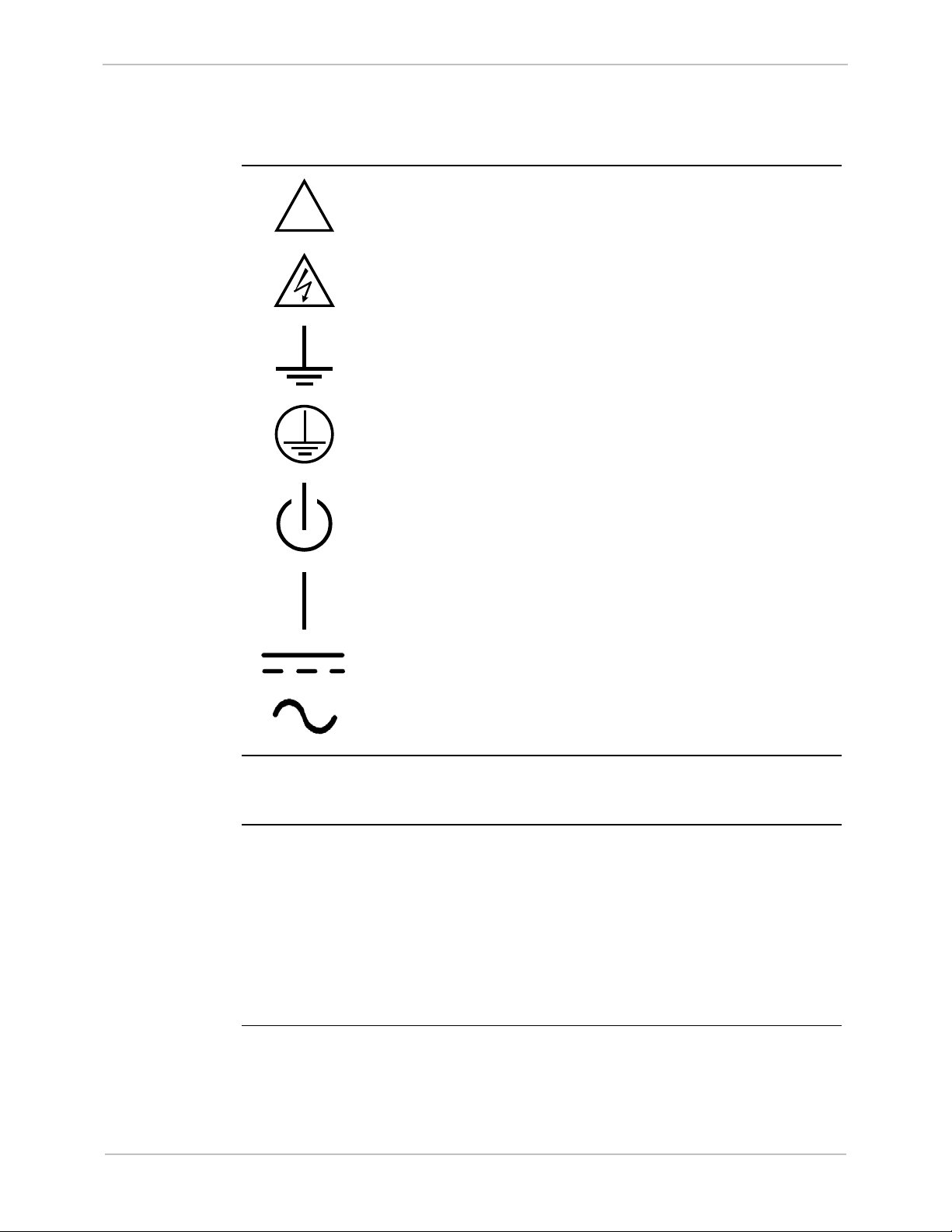
Symbols
Caution (refer to accompanying documentation)
Caution (risk of electric shock)
Earth/Ground Terminal
Protective Earth Terminal
Power Supply Off (Stand-by Mode)
Power Supply On
Direct Current
Alternating Current
Damaged
Equipment
Operating
Environment
GE Information
Do not operate an iBox or iBox Kit if it has been dropped or damaged. Return it to
GE Digital Energy for inspection and repair.
iBox/iBox Kits are intended for indoor use. Do not place these products in
environments where unusual environmental conditions exist (such as dirt, liquids, or
windblown dust) without a secondary protective enclosure.
For proper fire protection, iBox/iBox Kits must be installed in an enclosure equipped
with a metal floor with no openings.
An IEC
®
60947 compliant main disconnect switch (or other equivalent device
complying with IEC 60947-1 / 60947-3) must be as electrically close as practicable
to the iBox power supply.
994-0047-5.10-4
Page 10

iBox/iBox Kit
Installation and Maintenance Guide
10
!
!
Protection
during
Maintenance
RF
Interference
Rack Spacing
GE Grid Solutions
Ensure iBox/iBox Kits are protected from falling debris during maintenance. Small
metallic particles (such as wire clippings) could fall onto circuit boards and damage
or interfere with the safe and reliable operation of the iBox/iBox Kit.
The iBox/iBox Kit generates radio frequency (RF) energy that can radiate if it is not
installed and used in accordance with the instructions provided in this guide. This RF
energy may cause harmful interference to radio communications or sensitive circuits.
Operating an inadequately shielded iBox or iBox Kit in a residential area may cause
harmful interference, if this happens, you may be liable to correct the interference.
When mounting multiple iBox/iBox Kits in a rack (or when mounting an iBox/iBox
Kit in a rack with other equipment), verify that there is at least one rack unit (RU) of
space above and below the iBox/iBox Kit, to allow for cooling airflow, and for
routing cables between field equipment and the iBox/iBox Kit (1 RU = 1.75 inches).
Power and
Fusing
Grounding
Communication Cables
• For proper operation, input voltages must be within specified limits. Do not
apply voltages outside this range, since this may lead to premature product
failure.
• Always fuse-protect field sources.
• Always replace fuses with fuses of the same type and rating. Fuse types and
ratings are stated in the product specifications.
To ensure voltage transients are properly shunted to ground, you must connect the
iBox’s protective earth terminal to a low-impedance ground point using a braided
cable or heavy solid copper conductor.
When making ground connections, ensure all grounding surfaces are free of dirt,
residue and corrosion. You can use a coating such as Glyptal
®
to protect connections
from oxidation and dirt deposits.
Cable shields should be grounded to either the iBox/iBox Kit ground terminal or to
field equipment, but not to both. Do not ground cable shields at more than one point,
since potential differences between the ground points will result in ground loops and
undesirable noise sources.
• Use shielded cables to prevent electromagnetic interference.
• Route all communication cables away from power-carrying cables, and make
these cables as short as possible.
• Prior to start-up, verify the integrity of all communication cables and
connections.
994-0047-5.10-4 GE Information
Page 11

GE Grid Solutions
iBox/iBox Kit
Installation and Maintenance Guide
11
!
Safety Precautions, continued
Surge
Protectors
iBox Cover
iBox Jumpers
When connecting the iBox/iBox Kit to communications equipment (for example,
modems or radios), use appropriate surge arrestors to protect the iBox’s
communications ports.
Never operate an iBox without having its protective cover installed, since product
performance may be compromised, and equipment may be damaged if foreign
objects fall into the unit.
Configure the jumpers in your iBox before you connect field inputs and outputs.
Use of the equipment in a manner not recommended or specified by GE Digital
Energy, may impair the protection provided by the equipment.
GE Information
994-0047-5.10-4
Page 12
iBox/iBox Kit
Installation and Maintenance Guide
12
Connection
Ferrite Clamp
Cable/Wiring
CISPR 11-CE Mark Compliance
GE Grid Solutions
Important
Ferrite Clamp
cabling/wiring
Part Numbers
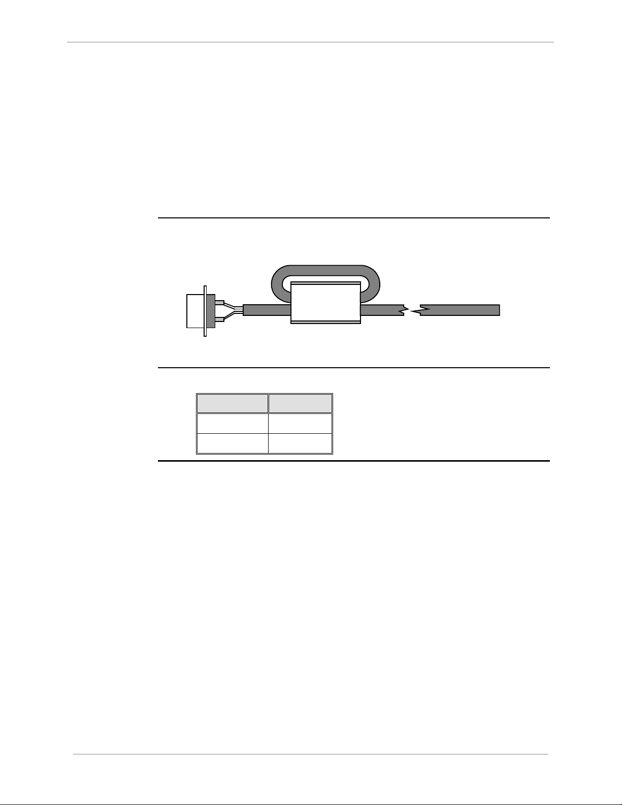
For CISPR 11, Class A-CE Mark compliance on an iBox installed outside of a
protective enclosure, you must use ferrite clamps on the following:
• Serial communication cables attached to J2, J3, and J4
• Wiring connected to TB2-TB15 for digital inputs and control outputs
Note: Although the standalone iBox is CE Marked, GE does not guarantee the CE
Mark of third-party components of the iBox Kits (such as the 10/100BaseT Ethernet
Module or the AC and DC Analog Input Modules).
The following diagram illustrates the cabling/wiring loop through an installed ferrite
clamp.
Order the following part number for each of the external ferrite clamps you require.
Part Number Color
460-0031 White body
460-0049 Black body
994-0047-5.10-4 GE Information
Page 13

GE Grid Solutions
iBox/iBox Kit
Installation and Maintenance Guide
13
Section 1: Getting Started
Overview
Introduction
Before you begin installing the iBox, review the information in this section,
including the following topics:
• Description of the iBox
• Unpacking and inspection
• Storage
• Installation Tools
GE Information
994-0047-5.10-4
Page 14

iBox/iBox Kit
Installation and Maintenance Guide
14
1.1. What is an iBox?
Product Overview
GE Grid Solutions
Introduction
Integrated
Functions
Scalable
Architecture
Features
The iBox is GE Digital Energy small point count Substation Controller. It combines
advanced functionality, multiple communication ports and local I/O in a compact
package.
The iBox processes both digital inputs and digital outputs. It also provides serial
digital data communication ports to facilitate communications with both a masterstation and local communications. The iBox is specifically designed for SCADA
applications.
The iBox Kit is a rack-mounted, pre-wired, pre-configured RTU based on the iBox,
but with additional (optional) power supply, Ethernet and I/O support.
The iBox can function as a:
• Programmable logic controller (PLC)
• IED gateway
• Data concentrator
• Standalone remote terminal unit (RTU).
The iBox’s flexibility makes it an excellent option for:
• Advanced substation monitoring
• Control
• Automation applications.
The iBox has three software-configurable RS-232/485 serial communication ports.
All three RS-232/485 serial ports interface to legacy IEDs or Master stations.
Patent
Protection
An extensive library of application software is available from GE Digital Energy to
enable the iBox to interface with a wide range of IEDs.
A UTC port is available for global satellite time synchronization (however, there
are three serial ports, so if you use one as a UTC port, two serial ports remain for
connecting to IEDs).
Maintenance port support provides access to SGConfig, LogicLinx*, and
WESMAINT* utilities.
Meets the robust requirements of the IEEE
®
, IEC® and CE Mark.
The iBox contains a patent protection label as a formal declaration of the US patents
that protect both the product and the technology developed by GE Digital Energy.
MAY BE PROTECTED BY ONE OR
MORE OF THE FOLLOWING US
PATENTS:
5237511, 5303112, 5513061, 5701226.
994-0047-5.10-4 GE Information
Page 15

GE Grid Solutions
iBox/iBox Kit
Installation and Maintenance Guide
15
System Software
Overview
Base System
Software
iBox
BootROM
Base
Applications
WIN
The iBox system software consists of two components:
• Base System
• Applications.
The Base System software provides a stable operating environment for applications,
which provide specific functionality for the iBox. The Base System is made up of:
• Boot software, resident in the BootROM, and
• Base applications, required for operating the hardware.
BootROM software is stored in EPROM. The BootROM contains:
• Operating system software
• Device drivers to interface the operating system with the system hardware and
software
• Diagnostic software, to verify the integrity of the iBox
• Monitor interface, for examining the system in a non-operational mode
• Startup code, to verify and initialize the application software
• Low-level maintenance and troubleshooting software
Standard iBox Base Applications, present in every iBox, are:
• WIN, the system database manager
• WESMAINT, which allows the operator to locally examine and control data
• 68K Monitor, which provides low-level system maintenance and diagnostic tools
WIN (for WESDAC Interface Node) is the database manager for the iBox System
Point Database. The System Point Database is the heart of the iBox software system.
All data flowing through the iBox is stored in the System Point Database before it is
passed on to its destination.
GE Information
994-0047-5.10-4
Continued on next page
Page 16

iBox/iBox Kit
Installation and Maintenance Guide
16
System Software, continued
GE Grid Solutions
WESMAINT
Database
Display
Other
WESMAINT
Functions
WESMAINT is the iBox’s primary maintenance and diagnostic tool. You can access
WESMAINT in three ways:
• Through the iBox WESMAINT port
• Through a modem or other serial connection to a programmed COM port
• Over a LAN or serial PPP connection, as a telnet session from a remote network
station
WESMAINT is accessed using a VT100 terminal, or a PC running terminal
emulation software.
Through WESMAINT, you can access the following:
• Digital inputs and outputs
• Counters (or accumulators)
• Device status
• Sequence-of-events (SOE) and change-of-state (COS) data
• System status information
• Error log information
• User login buffer
• Other application-specific information
In addition to displaying information, a WESMAINT user can also:
• Set or clear accumulator counts
• Operate digital outputs
• Clear logged information
• Access the iBox 68K Monitor.
994-0047-5.10-4 GE Information
Page 17

GE Grid Solutions
iBox/iBox Kit
Installation and Maintenance Guide
17
Note
System Software, continued
68K Monitor
The iBox 68K Monitor, available through WESMAINT, is a diagnostic tool used to
access system-level functions.
The iBox 68K Monitor is resident in both BootROM and flash memory.
When the Monitor is operated from BootROM, the following prompt appears:
D25S>. This mode is accessed only while the iBox is in a maintenance state, since
forcing an iBox into this mode terminates all running applications.
When the Monitor is operated from flash, the following prompt appears: D25A>.
This is the normal mode of operation, and it can be accessed via WESMAINT at any
time without disrupting unit operation.
Using the 68K Monitor requires detailed knowledge of the iBox architecture and
functionality. Refer to the 68K Monitor User’s Guide (SWM0023) for complete
instructions about command usage and availability.
GE Information
994-0047-5.10-4
Page 18

iBox/iBox Kit
Installation and Maintenance Guide
18
Application Software
GE Grid Solutions
Background
Data
Collection
Applications
Data
Processing
Applications
Data
Translation
Applications
Firmware
A wide range of applications can be added to the iBox to enhance its functionality.
Software applications fall into three categories:
• Data Collection Applications (DCA)
• Data Processing Applications (DPA)
• Data Translation Applications (DTA)
Data Collection Applications are used to import (collect) data from external sources,
and to pass this data to WIN (the system point database manager) for storage in the
system database. DCAs also forward output requests from the system database to
external sources.
Data Processing Applications are configured to select and format data from the
system database, and forward this data to a SCADA host or master station
A combination of a DPA and a DCA, Data Translation Applications use data from
the system database to perform logical operations, the results of which create new
data. This new data is then placed back in the system database, where it can be used
as input/output data by another application.
The set of applications installed on an iBox is referred to as its “firmware”.
Firmware is installed in the iBox flash memory prior to shipment. The iBox
operational characteristics can, however, be upgraded at a later date.
Contact your GE Digital Energy representative for more information on firmware
upgrades.
994-0047-5.10-4 GE Information
Page 19

GE Grid Solutions
iBox/iBox Kit
Installation and Maintenance Guide
19
Plant I/O Subsystem
Plant I/O
Subsystem:
Overview
Plant I/O
Subsystem:
Functions
Fixed Number
of Points
The iBox Plant I/O Subsystem collects, processes, and stores data related to physical
inputs and outputs. Once it is stored in the system database, I/O point data can be
accessed by other applications.
The Plant I/O Subsystem is responsible for scanning of iBox physical I/O points. For
input type points (digital and accumulator), the data of each scan is compared to
previous known data. Changes are recorded in the system database, then reported to
other applications, as needed.
The Plant I/O Subsystem:
• Scans and processes up to 8 digital inputs
• Controls up to two digital outputs and two master trip/close relays.
Requests for digital outputs are accepted and processed as soon as they arrive.
The Plant I/O DCA maintains a fixed number of points in the System Point
Database. The actual number of points is determined by the version of the P097 Plant
I/O Subsystem that has been installed on your iBox.
The hardware options available in the iBox (and the user’s software configuration)
determine if specific system features and data points are available or disabled.
GE Information
994-0047-5.10-4
Page 20
iBox/iBox Kit
Installation and Maintenance Guide
20
Part Number Label
1.2. Unpacking and Inspection
Shipping
Inspection
Unpacking
Inspect the shipping package before opening it to see if it has sustained any damage
from impact or water. If it has, report it immediately to the carrier without opening
it. Carriers may not assume responsibility for damage after the customer accepts
delivery.
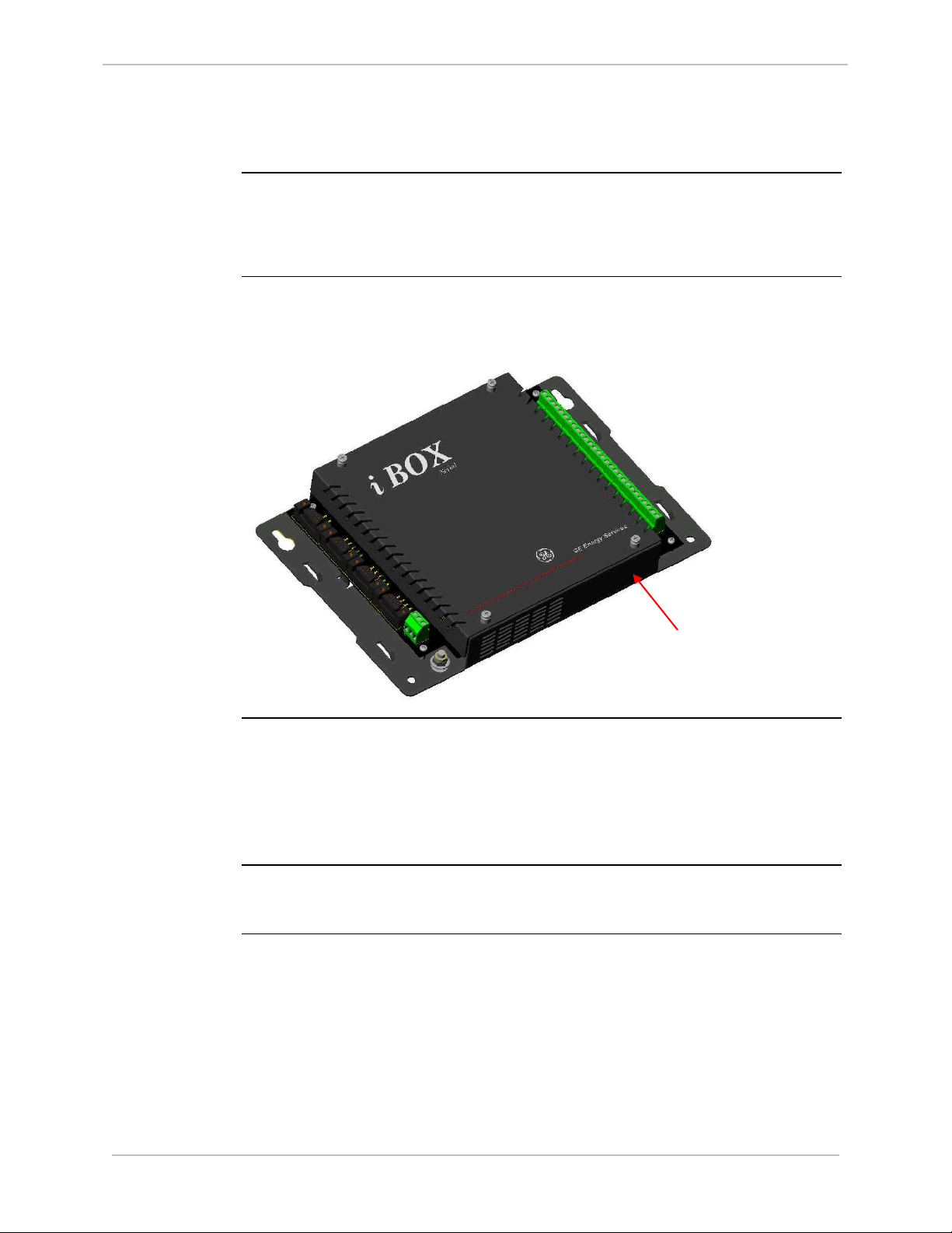
Carefully remove the iBox from its shipping package. Visually inspect the unit to
ensure it has not sustained any visible damage during transit.
The figure below shows an iBox removed from the shipping package.
GE Grid Solutions
Package
Contents
Product
Identification
Location
The following items are provided as part of your iBox shipment:
• iBox or iBox Kit unit
• WESMAINT serial cable
• IBOX/iBox Kit Installation and Maintenance Guide (994-0047)
• CD including the software and copy of user documentation
Before installing the unit, check that the unit part number is the same as the part
number on the shipping and ordering documents.
994-0047-5.10-4 GE Information
Page 21

GE Grid Solutions
iBox/iBox Kit
Installation and Maintenance Guide
21
Unpacking and Inspection, Continued
Part Numbers
This table contains part numbers and descriptions for each iBox variant:
Part Number iBox Description
505-0100 24 V Digital Input and 4 Trip/Close Control Outputs
505-0101 48 V Digital Input and 4 Trip/Close Control Outputs
505-0102 110/125 V Digital Input and 4 Trip/Close Control Outputs
505-0103 24 V Digital Input and 2 Trip/Close and 2 Form A Control Outputs
505-0104 48 V Digital Input and 2 Trip/Close and 2 Form A Control Outputs
505-0105 110/125 V Digital Input and 2 Trip/Close and 2 Form A Control
Outputs
Note: Part Numbers are subject to change without notice.
GE Information
994-0047-5.10-4
Page 22

iBox/iBox Kit
Installation and Maintenance Guide
22
1.3. Storage
GE Grid Solutions
Environment
Battery Life
Recycling of
Batteries
Specifications for storage are:
• Temperature: -40° to +90°C
• Relative humidity: 0 to 95%, non-condensing
As a general rule, always store your iBox in an environment compatible with
operating conditions. Refer to Appendix A: Technical Specifications for more
detailed environmental specifications
Exposure to excessive temperature or other extreme environmental conditions might
cause damage and/or unreliable operation.
The iBox battery maintains the unit’s NVRAM contents for over five years, with
system power applied.
If you are storing your iBox for extended periods, you should disconnect the battery
by removing the iBox’s top cover and pulling the battery out of the chassis.
If you are storing a new iBox which has the battery “PULL” tab in place, you do not
need to remove the battery for storage; the “PULL” tab disconnects (insulates) the
battery function.
The iBox Lithium battery is recyclable and does not contain mercury, cadmium, or
lead in levels above those regulated by the European Union. Recycle the battery
according to local waste management regulations.
In accordance with European Directive 2006/66/EC, batteries are marked with the
crossed out wheeled bin, which indicates that they cannot be disposed of as unsorted
municipal waste in the European Union. Users of batteries must use the collection
points available to customers for the return, recycling, and treatment of batteries.
Customer participation is important to minimize the negative effects of batteries to
the environment and sustain available natural resources. For more information see
www.weeerohsinfo.com.
994-0047-5.10-4 GE Information
Page 23

GE Grid Solutions
iBox/iBox Kit
Installation and Maintenance Guide
23
1.4. Installation Tools
Tools for the
Job
ESD
Protective
Gear
Before beginning the installation procedure, ensure you have the following tools and
equipment:
• A Windows PC with HyperTerminal (or any Windows based terminal
emulation software) loaded
• Ethernet Cable[s]
• A flat screwdriver with 0.6 x 3.5 mm blade (for terminal block wiring)
• A #2 Phillip-Server Screwdriver (for rack mounting the unit)
• A #1 Phillip-Server Screwdriver (for removing and installing the communication
boards)
• Needle Nose Pliers
• Wire Cutters
• Wire Strippers
• Wire Crimping Tool (Panduit
• 6 fork connectors
• Fork type Panduit part number PV14-6F for 14-16 AWG wire or PV18-6F for
18-22 AWG wire (or equivalent)
It is recommended that the following ESD gear be used during installation:
• Wrist Straps
• Foot Straps
®
CT-1525 or equivalent).
GE Information
994-0047-5.10-4
Page 24

iBox/iBox Kit
Installation and Maintenance Guide
GE Grid Solutions
24
Section 2: iBox Installation and Maintenance
Overview
Introduction
This section covers the following topics:
• Familiarization of the iBox
• Installing the iBox
• Configuring the iBox
• Testing the iBox
• Connecting and testing field wiring
• Servicing the iBox
• Maintaining the iBox software
• Troubleshooting the iBox
• Replacing the iBox
994-0047-5.10-4 GE Information
Page 25
GE Grid Solutions
iBox/iBox Kit
Installation and Maintenance Guide
25
2.1. Familiarization
Front Panel
As you look at the iBox, the:
• Left side has four DB9 connectors (serial ports), a three-position separable
terminal block (power connection), and a protective earth terminal.
• Right side has a 28-position terminal block for field I/O, separable in pairs.
Operation and
Maintenance
Inputs/
Outputs
Digital Inputs
You can operate and maintain the iBox configuration through the WESMAINT port.
The iBox provides the following:
• Eight digital inputs
• Four control outputs
The iBox provides the following digital inputs:
• Eight optically isolated status inputs, 25
VDC or 125 VDC, with 20% overload
• Wetting options
• LED indications
• 4-5 mA typical current burden per input (up to 48
VDC)
• Maximum 0.5 W heat dissipation per input from current burden of inputs at
125
VDC
GE Information
994-0047-5.10-4
Page 26

iBox/iBox Kit
Installation and Maintenance Guide
26
Familiarization, continued
GE Grid Solutions
Continued on next page
Control
Outputs
The iBox provides the following control outputs:
• Four Trip/Close pairs, or two Trip/Close pairs and two Form A contacts.
• Separate Master Trip and Master Close relays
• Security features:
− Protection against erroneous operation due to single point of failure
− Select-before-operate (SBO) functionality
• 35
W breaking @ 125 VDC, 180 W breaking @ 30 VDC
• 6
A current handling capability
994-0047-5.10-4 GE Information
Page 27

GE Grid Solutions
iBox/iBox Kit
Installation and Maintenance Guide
27
2.2. Installing the iBox
Overview
Safety
Precautions
Installation
Steps
Before beginning to install the iBox, thoroughly review the “Safety Precautions” for
guidelines and warnings regarding the safe handling and installation of the product.
Installing the iBox involves the following main steps:
Step Action
1
2
3
4
5
6
Physically install the iBox.
Connect power source and serial interfaces.
Power up the iBox and check for normal operation.
Configure the iBox using SGConfig.
Test the iBox.
Connect and test field wiring.
GE Information
994-0047-5.10-4
Page 28

iBox/iBox Kit
Installation and Maintenance Guide
28
Installation Guidelines
GE Grid Solutions
Installation
Environment
Power Supply
Source
The iBox must be installed in an environment that provides protection against shock
and fire hazard.
The iBox enclosure is intended for indoor use, primarily to provide protection
against accidental contact with the enclosed modules and voltages. Do not place the
product in environments where unusual conditions exist (windblown dust and dirt,
for example) unless you install it in a secondary protective enclosure.
Never operate an iBox in the field with the top cover removed. Operation with the
top cover removed may alter product performance specifications, and result in
component damage from foreign matter entry.
Do not install and/or operate the iBox upside down.
Ensure all nuts and screws are tightened securely.
Ensure that iBox is protected from falling debris during installation.
An IEC
®
60947 compliant main disconnect switch (or other equivalent device
complying with IEC 60947-1 / 60947-3) must be as electrically close as practicable
to the iBox power supply.
For correct iBox power supply operation, the input voltage must be within specified
limits.
The iBox DC power supply draws an inrush current (less than 0.5 A) upon start-up.
Ensure the field source can supply this start-up current without overloading.
Continued on next page
994-0047-5.10-4 GE Information
Page 29

GE Grid Solutions
iBox/iBox Kit
Installation and Maintenance Guide
29
Installation Guidelines, continued
Power Fusing
Grounding
and Shielding
Communications Ports
and
Connections
Always replace fuses with the same type and rating used by GE Digital Energy. The
fuse types and ratings are stated in “Fuse Replacement” on page 59.
Always fuse-protect field power sources.
To ensure safe operations, you must connect the iBox Protective Earth Terminal to a
low impedance ground using braided cable or heavy solid copper conductor. When
making ground connections, ensure all grounding surfaces are free of dirt, residue
and corrosion.
Ensure cable shields are grounded at either the iBox functional ground terminal or at
the field equipment. Do not ground the shields at more than one point because a
potential difference may exist between grounds, resulting in ground loops and
undesirable noise sources.
To prevent electromagnetic interference from upsetting iBox operation, use cables
with an over-all cable shield. Route all communication cables away from powercarrying cables.
Verify the integrity of all communication cable connections prior to start-up to avoid
damaging the iBox.
Serial ports are protected with surge and noise suppression components.
Always shield communication cables and make them as short as possible.
GE Information
994-0047-5.10-4
Page 30

iBox/iBox Kit
Installation and Maintenance Guide
30
Physical Mounting
GE Grid Solutions
Procedure:
Mounting the
iBox
Mounting and
Clearance
Step Action
1
2
Align the iBox in its proper position on a flat mounting surface.
Install and tighten the four screws, holding the iBox firmly in place on
the mounting surface.
3
Loosen the iBox top cover and remove the battery “PULL” tab. The
iBox is delivered with this tab in place to insulate the battery during
shipment.
Leave at least one rack unit (RU) of space above and below the equipment to allow
for cooling air flow and cable routing (1 RU = 1.75 inches or 44.5
mm).
994-0047-5.10-4 GE Information
Page 31

GE Grid Solutions
iBox/iBox Kit
Installation and Maintenance Guide
31
!
!
+ – Chassis
TB1
Terminal Connections
Power Supply
Functional
Ground/
Chassis
Internal
Overcurrent
Protection
The iBox’s power supply connection is a three-position terminal block located on the
bottom left side of the iBox. This removable terminal block must be disconnected to
turn off the power supply input. The iBox does not have an ON/OFF switch.
Connect the ground screw terminal to the facility’s ground system before operating
the iBox. Before making this connection, ensure all grounding surfaces are free of
dirt, residue and corrosion. The maximum wire gauge for terminal blocks is 12
AWG.
An internal MDL 0.5 A (slow blow) fuse protects the iBox power supply.
Power
Connection
Procedure
To connect the power source:
Step Action
1
Connect ground wire to the ground terminal. A 12 AWG green and
yellow wire is recommended.
2
Connect the DC power supply, observing the correct polarity, to the
positive and negative connection points on TB1
The chassis ground terminal at the power supply terminal block must not be used as
a protective earth connection.
Make sure the iBox is properly grounded to the protective earth terminal located at
the bottom-left corner of the board. Connection must be provided with a separate
green/yellow wire connected between the iBox and the facility’s ground system.
GE Information
994-0047-5.10-4
Page 32

iBox/iBox Kit
Installation and Maintenance Guide
32
System Diagnostics
GE Grid Solutions
System
Diagnostics
LEDs
Diagnostics
Completed
Once power is applied, the iBox automatically boots and conducts a series of selfdiagnostic tests. If the iBox fails to boot up properly (which indicates that a selfdiagnostic failure has occurred), it might have sustained internal damage during
shipping. Contact GE Digital Energy for assistance.
The POWER and RUN LEDs will both light during the self-diagnostic sequence.
Self-diagnostics have completed successfully when the POWER and RUN LEDs are
on solid.
994-0047-5.10-4 GE Information
Page 33

GE Grid Solutions
iBox/iBox Kit
Installation and Maintenance Guide
33
Terminal - DB-9 Female
WESMAINT - DB-9 Male
COM
N/C
TXD
RXD
N/C
N/C
N/C
N/C
N/C
N/C
RXD
TXD
N/C
COM
N/C
N/C
N/C
GND
1
2
3
4
5
6
7
8
9
1
2
3
4
5
6
7
8
9
Connecting Serial Interfaces
WESMAINT
Port
WESMAINT
Cable
The iBox is equipped with a WESMAINT port. By attaching a WESMAINT cable
between the WESMAINT port and your PC, the iBox can:
• Provide local maintenance and diagnostic functionality
• Download configuration data from the optional SGConfig software
With the cable connected, you can also upload diagnostic and operational
information to the PC.
The WESMAINT interface supports RS-232 signaling and normally operates at a
fixed rate of 9600 bps.
To connect to a PC, use a WESMAINT cable (GE part number 977-0048/96), or
equivalent.
The schematic for this cable is shown below:
Standard
Serial
Interfaces
GE Information
The iBox has three serial communications ports: COM1, COM2, and COM3
All COM ports have the following standard characteristics:
• Female DB-9-F style connectors
• RS-232 and RS-485 are supported on the same physical connector.
994-0047-5.10-4
Continued on next page
Page 34

iBox/iBox Kit
Installation and Maintenance Guide
34
Connecting Serial Interfaces, continued
GE Grid Solutions
COM1
Options
COM2
Options
IRIG-B Output
Options
COM Ports
COM Port
Options
In addition to the standard characteristics, COM1 has the following optional
characteristics:
• Jumper-selectable (JP3) radio key, open-collector output
• Communication parameters, determined by the protocol application.
COM2 can optionally be used to connect to a satellite time-code receiver, as follows:
Time code J3 Pin Interface Signal
IRIG-B 8 RS-232 CTS2
Rugby Clock 2 RS-232 RX2
5 RS-232 COM
IRIG-B receivers are available with modulated and/or unmodulated output options. If
the unmodulated output of the receiver is a coaxial connection, a converter will be
required to interface to the iBox.
COM ports provide the following:
• Variable communication parameters
• Optional software flow control
• Optional hardware flow control
• Out-of-sequence transmission of one byte of data
• Support for several I/O timers
• Transmission of break characters
The COM1, COM2 and COM3 serial ports are programmed using SGConfig for:
• RS-232 or RS-485
• RS-485 2-wire or 4-wire (2W/4W)
Note: The 2W/4W selection in SGConfig only affects the interface’s internal
software control (handshaking). It does not change the physical
characteristics of the communication ports.
994-0047-5.10-4 GE Information
Page 35

GE Grid Solutions
iBox/iBox Kit
Installation and Maintenance Guide
35
Description PIN #
1
2
3
4
5
6
7
8
9
N/C
Data Data -
N/C
Common Ground
N/C
Data +
Data +
Earth Ground
- TX / RX
+ TX / RX
iBox Connectors J2, J3 or J4
Connecting Serial Interfaces, continued
Serial Port
Pinouts
2-Wire RS-485
Cable
The COM port pin-outs, for both RS-232 and RS-485 configurations, are as follows:
DB-9 Pin RS-232 RS-485
1 CD N/C
2 RX RX-
3 TX TX-
4 N/C N/C
5 Com GND Com GND
6 N/C* N/C
7 RTS TX+
8 CTS RX+
9 EARTH GND EARTH GND
* Radio Key Open Collector Output for COM Port 1 only (jumper selected with JP3
installed).
The following schematic shows the cable wiring necessary for 2-wire RS-485
operation.
GE Information
994-0047-5.10-4
Page 36

iBox/iBox Kit
Installation and Maintenance Guide
36
2.3. Configuring your iBox
Overview
GE Grid Solutions
Introduction
Configuration
Template
Configuration
Steps
You can create a project for configuring your iBox device using SGConfig.
A sample configuration is included on the CD with the iBox. You can create the
iBox device configuration starting from the sample configuration or create a new
configuration from scratch.
After you successfully create a device configuration, you can use it as a template for
all subsequent iBox configurations. To do so, copy the original configuration file,
and edit the copied file as necessary.
After creating the device, the remaining procedures are the same, whether you are
working with a copy of an existing configuration or creating a new device
configuration.
The iBox is configured using the SGConfig configuration system.
Configuring the iBox involves the following main steps:
• Create or restore a SGConfig project.
• Create and configure the iBox device in the project.
• Configure the application firmware.
• Configure the Plant I/O.
• Download the configuration to the iBox.
Before you
Start
For the detailed procedures, refer to the SGConfig online help.
To configure the iBox, you will need the following items:
• Factory configuration for your iBox. You can find this on the configuration CD
that shipped with your iBox.
• SGConfig installed on your PC.
• Serial number of your iBox, from the iBox circuit board
994-0047-5.10-4 GE Information
Page 37

GE Grid Solutions
iBox/iBox Kit
Installation and Maintenance Guide
37
Restoring your SGConfig Project
Introduction
Procedure:
Restoring
your
SGConfig
Project
This procedure describes how to restore the SGConfig project that includes the
sample configuration provided with the iBox.
Step Action
1 In your Windows desktop, click Start, and then click Programs.
2 Click SGConfig, > SGConfig.
Result: SGConfig opens.
Importing the Factory Configuration
3 Click GE > Archive > Project > Restore.
4 Click Restore.
Result: The Restore Project Details window appears:
5 Insert your configuration CD in the drive.
6 Navigate to the configuration file in the Archive File Name field.
7 Click OK.
Result: The configuration file uploads to your PC, and your project
appears in an SGConfig project tab.
GE Information
994-0047-5.10-4
Page 38

iBox/iBox Kit
Installation and Maintenance Guide
38
Creating a New iBox Device
GE Grid Solutions
Introduction
iBox Device
Icon
Procedure:
Creating a
New iBox
Device
Creating an iBox device in SGConfig has two main steps:
• Create the new device
• Specify the device properties
This procedure assumes that you are using the default firmware already loaded in the
iBox or have created a firmware set.
When you create a new iBox device, select the iBox device template to see the
appropriate configuration screens.
To create a new iBox device:
Step Action
1 Open the project in which you want to create the iBox device.
2 Drag and drop an iBOX device template from Local Repository >
Device Templates into the project tab area.
3 Click Edit group > Properties command.
Result: The iBOX Device Wizard appears.
4 In the Name box, type a unique name for the device.
5 Continue to “Procedure: Setting iBox Device Properties”.
Continued on next page
994-0047-5.10-4 GE Information
Page 39

GE Grid Solutions
iBox/iBox Kit
Installation and Maintenance Guide
39
Procedure: Creating a New iBox Device, continued
firmware definitions.
esenting your new device, appears in the main proje
iBox Device
Properties
Procedure:
Setting iBox
Device
Properties
Once you have created the iBox device, follow the procedures below for setting the
iBox device properties.
To set the iBox device properties:
Step Action
Hardware Tab
1 In the iBox Device Wizard window, click the Hardware tab.
2 Click the Memory Model tab. You should not need to change the Base
System and Global Variable Area settings. If necessary, change the
NVRAM Area value to suit your specific system.
3 On the Serial I/O tab, configure each com port for RS-232 or RS-485
communications.
Note: The 2W/4W selection in SGConfig only affects the interface’s
internal software control (handshaking). It does not change the
physical characteristics of the communication ports.
New Device
Icon
Processor Tab
4 Click the Processor tab.
5 On the Firmware tab, click the Select button to display the available
6 In the Use Firmware Type field, select the firmware definition that
matches your iBox’s applications.
Result: The Name field shows the name of your firmware selection.
7 From the Memory Model tab, check that Derive From iBox
Hardware Setting is selected.
8 Click Close to complete the creation of the new iBox device.
The wizard closes.
After you complete these steps, an iBox icon, repr
window. The new iBox device is now ready to be configured.
GE Information
994-0047-5.10-4
Page 40

iBox/iBox Kit
Installation and Maintenance Guide
40
Configuring Application Firmware
Overview
Procedure:
Digital Input
Configuration
The iBox uses the D25 Plant I/O Subsystem (P097) Data Collection Application to
configure the digital inputs. Configure the iBox Plant I/O before you configure the
points in the System Point Database application.
To configure the DC digital inputs:
Step Action
1 Configuring the iBox PPP Driver and Internet Data
2 Double-click the D25 Plant I/O Subsystem icon.
Result: The D25 Plant I/O for iBox dialog box appears.
3
Double-click the DC Configuration icon.
Result: The D25 DC Configuration for iBox dialog box appears.
4 On the General tab, select the type of digital input board from the First
Digital Input board list. Select one of:
• C: iBox 8 channels, 24 V wetting
• D: iBox 8 channels, 48 V wetting
• E: iBox 8 channels, 125 V wetting
The other board settings are preset.
GE Grid Solutions
Other
Application
Configuration
Result: The letter in the Device Code changes to match your selection.
Note: Refer to the on-line help in SGConfig for details on configuring
the I/O Configuration and Advanced tabs.
Configure your other applications before continuing to install the iBox. Each
application has its own configuration process. Refer to the documentation for your
specific applications for configuration information.
994-0047-5.10-4 GE Information
Page 41

GE Grid Solutions
iBox/iBox Kit
Installation and Maintenance Guide
41
Downloading your iBox Configuration
Procedure:
Downloading
your iBox
Configuration
Step Action
1 If you have not already done so, connect your PC to the iBox
WESMAINT port and open SGConfig.
2 In the SGConfig Project window, click the iBox device icon.
3 Click Communications group > Connect > TeraTerm command.
Result: The TeraTerm window appears within an SGConfig tab.
4 Press ENTER.
Result: SGConfig prompts you to enter a user name.
5 Type westronic and press ENTER.
Result: SGConfig prompts you to enter a password.
6 Type your password (the default is rd) and press ENTER.
Result: The following screen appears:
7 Enter “2”.
Result: The following screen appears:
8 Enter “3”.
Result: The 68K Monitor command prompt appears.
9 In the command line, type el /r then press ENTER.
Result: The iBox clears its error log.
Tip: To speed up the configuration download, temporarily change the
baud rate of the WESMAINT serial port from the default 9600 baud to
38400 baud in WESMAINT and SGConfig.
To change the baud rate:
• In WESMAINT, enter baud 38400 at the 68K command line.
• In the SGConfig Terminal Emulator window, on the
Communications menu, click Options. On the Port Settings tab, set
the Baud Rate to 38400 and click OK.
Continued on next page
GE Information
994-0047-5.10-4
Page 42

iBox/iBox Kit
Installation and Maintenance Guide
42
complete.
Downloading your iBox Configuration, continued
GE Grid Solutions
Procedure:
Downloading
your iBox
Configuration
(continued)
Step Action
10 On the SGConfig click Terminal Emulator Connectivity group, click
Connect.
Result: SGConfig connects to the iBox and the 68K Monitor command
line appears.
11 On the SGConfig click Terminal Emulator Actions menu, click Sync To
Device.
Result: The configuration download starts.
A confirmation window appears when the download is
12 Click Reboot.
Result: The iBox reboots.
Note: If you changed the baud rate to 38400, the WESMAINT
communications rate automatically restores to 9600 baud after the
iBox reboots. You need to manually restore the SGConfig
terminal emulator communications rate to 9600.
13 From SGConfig, click the Connectivity group > Disconnect command.
Note: If you changed the baud rate to 38400, the WESMAINT
communications rate automatically restores to 9600 baud after the
iBox reboots. You need to manually restore the SGConfig
terminal emulator communications rate to 9600.
14 On the File menu, click Exit.
15 Physically disconnect your PC from the iBox.
994-0047-5.10-4 GE Information
Page 43

GE Grid Solutions
iBox/iBox Kit
Installation and Maintenance Guide
43
Configuring the iBox to work with a DNP3 I/O Module
Introduction
Your iBox RTU Master communicates with your DNP3 I/O modules through
the DNP3 Data Collection Application (DCA B023). The DNP DCA collects
data from, and sends control requests to, the DNP3 I/O modules.
Refer to Appendix F: Installing and Connecting DNP3 I/O Modules for
installation and connection instructions.
Use SGConfig to configure the DNP3 DCA in the iBox so that it
communicates with your DNP3 I/O module. There are three tables to
configure:
• Remote Device Table: This table contains one record for each DNP
I/O module in the system. The Remote Device Table specifies the
remote devices with which the DCA communicates, the polling
parameters for each remote device, and the points configured on each
remote device. Each record in the Remote Device Table references the
appropriate Remote Device Point Mapping Table(s) and Remote
Device Polling Table(s).
• Remote Device Point Mapping Table: Specifies the number and type
of data points associated with each DNP I/O module.
• Remote Device Polling Table: Specifies the polling type and frequency
for each DNP I/O module.
Instructions and guidelines for configuring your DNP3 DCA can be found in
the following documentation:
• DNP V3.00 DCA - Configuration Guide (B023-0CG)
• SGConfig online help.
Note: When configuring the Time Sync option:
• Disable Time Sync for the D20A and D20K modules
• If Time Sync is enabled on a D20S module, the polling rate may be a
minimum of 2 seconds (it takes about 850ms to do a Time Sync for each
device).
GE Information
994-0047-5.10-4
Page 44

iBox/iBox Kit
Installation and Maintenance Guide
GE Grid Solutions
44
For example, when configuring your iBox RTU Master to work with a DNP
Configuring the iBox to work with a DNP3 I/O Module, continued
Example
Configuration
Digital Input Module, assume that you have a DNP Digital Input Module:
• That is factory-configured with 64 digital inputs
• That has DNP address 0032
• Which is to be polled every 500 ms.
• With every poll, we want a full status update.
To meet these requirements, you would configure the DNP DCA as shown in
the below table:
Table Parameter Value
Remote Device Table Application Address 0032
Remote Device Point
Mapping Table
Remote Device Polling Table Poll Data Type Integrity
DCA Object Type Binary Input
Number of Device Points 64
Poll Interval 500 ms
994-0047-5.10-4 GE Information
Page 45

GE Grid Solutions
iBox/iBox Kit
Installation and Maintenance Guide
45
2.4. Testing your iBox
Overview
Introduction
Valid
Configuration
File Required
This section describes a number of system checks that you can perform to verify
your iBox software is functioning properly.
Before performing any of the tests in this section, you must have a valid
configuration file loaded into the iBox’s NVRAM. The iBox is typically shipped
with a valid configuration file loaded during manufacturing, and this file should be
still loaded when the unit is delivered to your site.
In the event that you do not have a valid configuration file loaded into your iBox’s
NVRAM, or the file becomes corrupted before the unit is installed, you must reload
the file before performing these verification tests.
For help restoring your configuration file, refer to the online help in SGConfig.
GE Information
994-0047-5.10-4
Page 46

iBox/iBox Kit
Installation and Maintenance Guide
46
LED Descriptions
GE Grid Solutions
Overview
Description
You can verify the iBox is operating properly by inspecting the LEDs on the iBox
chassis.
The iBox has the following LED indicators, all of which are GREEN.
LED Location Description
PWR Top left The POWER LED remains lit when the iBox is receiving
power.
RUN Top left The RUN LED flashes to indicate CPU bus activity. Brightness
indicates more CPU bus activity.
TX1 – TX3 Left side The TRANSMIT LED flashes when the iBox is transmitting to
an outside device. There are three transmit LEDs, one for
each communication port.
RX1 – RX3 Left side The RECEIVE LED flashes when the iBox is receiving a signal
from an outside device. There are three receive LEDs, one
for each communication port.
RS1 – RS3 Left side The Request to Send (RTS) LED only works on systems
configured for RS-232 communications. There are three RTS
LEDs, one for each communication port.
CS1 – CS3 Left side The Clear to Send (CTS) LED only works on systems
configured for RS-232 communications. There are three CTS
LEDs, one for each communication port.
CD1 – CD3 Left side The Data Carrier Detect (DCD) LED only works on systems
configured for RS-232 communications. There are three
DCD LEDs, one for each communication port.
I/P1 – I/P8 Right side Each of the iBox’s eight Digital Inputs (DI) has a LED that
remains lit when the DI is receiving a wetting voltage.
994-0047-5.10-4 GE Information
Page 47

GE Grid Solutions
iBox/iBox Kit
Installation and Maintenance Guide
47
Diagnostic Tools
General
WESMAINT
68K Monitor
To operate the iBox, you require the following system components:
• WESMAINT facility
• iBox monitor facility
• SGConfig configuration system.
Each iBox has a WESMAINT facility that allows users to examine the iBox
database, applications and communications, and to manipulate the data.
You can, for example, use WESMAINT to examine the state of digital input data, or
to force a digital output ON or OFF.
WESMAINT uses a series of menus and screens that display on a VT100 terminal,
or similar terminal emulator, to create a simple interface to the iBox.
With a VT100-compatible terminal emulation program or SGConfig, you can access
the WESMAINT facility directly.
Note: For further information about using WESMAINT software, refer to the
WESMAINTII+ User’s Guide (Document Number B014-1UG).
The iBox’s 68K Monitor is a debugging and diagnostics tool that is accessible in two
ways:
• As a menu selection available through WESMAINT
SGConfig
• Upon start-up of an iBox that has not been previously configured.
Note: For further information about using the iBox Monitor, refer to the 68K
Monitor User’s Guide (Document Number SWM0023).
Use SGConfig to define the iBox’s operating parameters. You can also use
SGConfig to download configuration files to the iBox through a serial connection.
Note: For further information about SGConfig, refer to the SGConfig online help.
GE Information
994-0047-5.10-4
Page 48

iBox/iBox Kit
Installation and Maintenance Guide
48
Boot Test Verification
GE Grid Solutions
System
Diagnostics
(POST)
Terminal
Emulation
Software
WESMAINT
Terminal for
Set-up
The iBox software includes a Power On Self-Test (POST) process, which runs when
the unit is powered ON and determines whether or not the iBox circuitry is working
properly.
Terminal emulation software is not part of the iBox system, but you can use terminal
emulation software such as HyperTerminal
®
or SGConfig terminal utility for these
tests.
Use the following procedure to set up a PC as a WESMAINT terminal:
Step Action
1
Open HyperTerminal (provided with Windows
®
operating system), or
other VT100-compatible terminal emulation software.
2
Verify (or set) the terminal communications settings as follows:
Data Rate
Data Bits
Stop Bits
Parity
Flow Control
9600 bps
8
1
None
XON/XOFF
Connector Settings
COM1, COM2, as required
for your computer
Continued on next page
994-0047-5.10-4 GE Information
Page 49

GE Grid Solutions
iBox/iBox Kit
Installation and Maintenance Guide
49
Boot Test Verification, continued
Connect to
the
WESMAINT
port
iBox Boot Up
Step Action
1
Connect a WESMAINT cable to the female DB-9 WESMAINT port on
the top left side of your iBox.
2
Attach the other end of the WESMAINT cable to the PC’s selected
communications port.
3
Verify the power cable is properly connected to iBox, and power is
available.
4
The POWER and RUN indicators on the front upper left-hand corner
illuminate when power to the iBox is turned ON.
5
Monitor the VT100 terminal’s display
Result: A series of text scripts displays as the POST routines are
performed. If you do not see the text scripts, check all
connections and repeat the procedure.
The iBox automatically boots as soon as the power is turned on.
If the iBox fails to boot up, it may have sustained damage during shipping. Contact
GE Digital Energy for assistance.
GE Information
994-0047-5.10-4
Page 50

iBox/iBox Kit
Installation and Maintenance Guide
50
Log in to WESMAINT
GE Grid Solutions
General
Procedure:
Logging into
Wesmaint
User Name
and Password
When the POST is complete, you can log in to WESMAINT to continue further
testing.
To log into WESMAINT from a PC:
Step Action
Press
1
ENTER
Result: The Welcome screen appears, as does a login prompt.
Note: If the Welcome banner does not appear, and only a <iBoxS
prompt displays, a valid code or configuration file is not loaded
into the iBox’s memory. Stop this procedure and refer to
“Downloading Code Files” on page 65 for procedures for
restoring files
2
3
Type the User Name: westronic and press
Type the Password: rd and press
ENTER.
ENTER.
Result: The WESMAINT Main Menu appears
4
If a time-out occurs, press
ENTER again, to return to the login prompt
The user name and password shown above are factory defaults. If you cannot log in,
contact your system administrator to obtain the correct user name and password.
Navigating in
WESMAINT
Further
WESMAINT
Information
Use the UP and DOWN arrow keys, or type in the menu number, to select an option
from the Main Menu. Press
CTRL+L at any time to log out of WESMAINT
For further information about using WESMAINT, refer to WESMAINTII+ User’s
Guide (Document Number B014-1UG).
994-0047-5.10-4 GE Information
Page 51

GE Grid Solutions
iBox/iBox Kit
Installation and Maintenance Guide
51
2.5. Connecting and Testing Field Wiring
Overview
Introduction
This section describes the process for making and testing field connections to the
iBox.
GE Information
994-0047-5.10-4
Page 52

iBox/iBox Kit
Installation and Maintenance Guide
52
Digital Inputs
GE Grid Solutions
Digital Inputs
Wetting Types
Digital Input
Thresholds
The iBox has eight digital inputs (DIs).
All DIs require an input voltage signal large enough to turn on an optical switch. If
the DI is receiving a sufficient wetting voltage, the green LED associated with the DI
will light.
The following table shows the iBox’s ON and OFF state thresholds. Verify that
inputs do not exceed the maximum overload voltage; otherwise, the iBox may be
damaged.
Digital Input
Options
24 VDC >14 VDC <5 VDC 24 VDC + 20%
48 VDC >28 VDC <10 VDC 48 VDC + 20%
110/125 VDC >80 VDC <20 VDC 125 VDC + 20%
On Threshold Off Threshold Max Overload Voltage
Low Voltage Digital Input
High Voltage Digital Input
994-0047-5.10-4 GE Information
Page 53

GE Grid Solutions
iBox/iBox Kit
Installation and Maintenance Guide
53
!
2
1 1 22 1
Input #1
Input #8
External Wetting
Power Supply
TB2 TB9 TB10
+/- V
Digital Input Configuration
Digital Input
Field
Connections
Digital Input
Wetting
Selection
Wiring
Diagram:
Dry Contact
Operation
Field wiring for all digital input variants are made through the iBox’s terminal
blocks, separable in pairs.
The digital input is wetted (or turned ON) by closing a contact across the two input
termination points. The voltage that is switched at the input terminals is supplied by
an external source. The external power source is connected to terminal block TB-10,
positions 1 and 2, as shown below.
All eight digital inputs are bipolar. Use care when connecting multiple external
power sources, since the digital inputs have common returns.
This diagram illustrates the DC input connections, from Input #1 (TB2) through
Input #8 (TB9). TB10 accepts DC voltages of either polarity. The input voltage level
to TB10 is determined by the purchased option.
GE Information
994-0047-5.10-4
Page 54

iBox/iBox Kit
Installation and Maintenance Guide
54
TB15
TB14
TB13
TB12
TB11
Trip 4
Close 4
Trip 3
Close 3
Trip 2
Close 2
Trip 1
Close 1
1 2 1 2 1 2 1 2 1 2 Master T/C
(+/- V)
GND
TB15
TB14
TB13
TB12
TB11
Trip 2
Close 2
Trip 1
Close 1
1 2 1 2 1 2 1 2 1 2 Master T/C
(+/- V)
GND
Digital Out 2
(Form A)
Digital Out 1
(Form A)
Digital Outputs
GE Grid Solutions
Operating
Modes
Wiring Four
Trip/Close
Outputs
(Part No.
505-0100,
505-0101,
505-0102)
Wiring Two
Trip/Close
and Two
Digital
Outputs
iBox control outputs have two modes of operation:
• Trip/Close (T/C) pairs
• Digital Output (DO) isolation Form A contacts.
Note: Using SGConfig, you must configure the digital outputs for four Trip/Close
outputs or two Trip/Close and two digital outputs, depending on the part number.
You can wire four trip/close outputs, as follows:
You can wire two trip/close and two digital outputs, as follows:
(Part No.
505-0103,
505-0104,
505-0105)
Important
Remote/Local
Operation
iBox digital outputs are not internally fuse-protected.
If: Then operation is:
JP2 is installed Remote (controls are enabled)
JP2 is removed Local (controls are disabled)
994-0047-5.10-4 GE Information
Page 55

GE Grid Solutions
iBox/iBox Kit
Installation and Maintenance Guide
55
The following procedure, accessible through the WESMAINT Main Menu, assumes
• Press N to move to the Next page
Digital Input Verification Test
Testing
Digital Inputs
Note
Procedure:
Testing
Digital Inputs
To view digital input changes through WESMAINT, log in to WESMAINT as
outlined in “Boot Test Verification” on page 48.
The quantity and relative position of data points in the iBox’s System Point Database
is determined by the version of the iBox Plant I/O software application present in
your iBox’s firmware.
You can determine the actual point number that you want to test by viewing the point
descriptions in WESMAINT, or through the SGConfig configuration tables for your
iBox.
The point descriptions viewed in WESMAINT will be modified by changes you
have made to the point descriptions in the iBox configuration file
digital inputs for the iBox are wired and wetted.
Step Action
1
Select 1 — Digital Input Display.
Result: The point numbers and (optionally) point descriptions appear
on the WESMAINT display
2
Use arrow keys to move up or down to highlight the desired point
number (or press
CTRL+G if you already know the point number)
3
Short out the desired input point, and verify, through WESMAINT, that
the point status has changed to ON.
4
Return to Step 2 to test other digital input points
Navigating
through
WESMAINT
• Press P to move to the Previous page
• Press
ESC to move back to the previous menu level.
GE Information
994-0047-5.10-4
Page 56

iBox/iBox Kit
Installation and Maintenance Guide
56
Note
!
Digital Output Verification Test
GE Grid Solutions
Testing
Digital
Outputs
Procedure:
Testing
Digital
Outputs
To force digital outputs through WESMAINT, first log in to WESMAINT as
described in “Boot Test Verification” on page 48.
The quantity and relative position of data points in the iBox’s System Point Database
is determined by the version of the iBox Plant I/O software application present in the
iBox’s firmware.
You can determine the actual point number that you want to test by viewing the point
descriptions in WESMAINT or in the SGConfig configuration tables for your iBox.
The actual point descriptions in WESMAINT will be modified by any changes you
have made to the point descriptions in the configuration file.
Use caution when testing digital output points that are connected to external
equipment. This test may activate or damage external devices, such as relays or
reclosers, and could injure personnel.
From the WESMAINT Main Menu:
Step Action
1
Select 1 — System Data Display
2
3
4
5
6
Select Digital Output Display
Result: The point numbers and (optionally) point descriptions appear
on the WESMAINT display.
Use arrow keys to highlight the desired point number (or press
CTRL+G
if you already know the point number).
Result: The cursor flashes on the specified point number
Press
CTRL+F when you are ready to force-change the state of the digital
output point.
Extra Security
At the Password prompt, type control and press
ENTER
Result: The Digital Output Force Display appears.
Press
CTRL+U to change (update) the relay state.
Continued on next page
994-0047-5.10-4 GE Information
Page 57

GE Grid Solutions
iBox/iBox Kit
Installation and Maintenance Guide
57
Procedure: Testing Digital Outputs, continued
Digital Output Verification Test, continued
Step Action
Notes
Test Failure
Repeat Test
Test Next
Point
7
8
9
10
Press the
In the Off time field, type 500 and press
In the On time field, type 500 and press
In the Repeat Command field, type 10 and press
SPACE BAR to select Pulse, and press ENTER.
ENTER.
ENTER.
ENTER twice.
Result: Listen carefully for an audible click of the point relay. A test is
considered successful if the relays click when forced.
11
12
13
14
15
For testing Trip/Close type operation, repeat steps 1- 6.
Press the
In the Off time field, type 300 and press
In the On time field, type 300 and press
SPACE BAR to select Trip/Close, and press ENTER.
ENTER.
ENTER.
In the Repeat Command field, type the value 0 and press
ENTER twice.
Result: Listen carefully for an audible click of the point relay. A test is
considered successful if the relays click when forced.
Note: For Trip/Close operation in Repeat Command field, if field
input value is other than zero it results in a WIN write request
failed error message with status 0x0011 (operation not supported
for this point).Refer to Appendix G: Error Messages.
Note: The password shown above is factory default. If you cannot log in, contact
your system administrator to obtain the new password.
Note: The number of times that a control will operate is actually N+1, where N is
the number of repeats entered in the Repeat command field. For a single
operation, with no repeats, type 0. For two operations, type 1.
If relays do not operate:
1. Ensure that the CONTROLS enable jumper is in the REMOTE position. No
error message appears in WESMAINT if the test fails
2. Reboot the iBox, and repeat the procedure
3. Call GE Digital Energy for assistance
To repeat the test sequence, press
CTRL+U, and then press ENTER.
Values entered for the previous test are retained until you exit the menu.
To test another point, use the
CTRL+U to repeat the test.
UP or DOWN arrows to cycle through points, then press
GE Information
994-0047-5.10-4
Page 58

iBox/iBox Kit
Installation and Maintenance Guide
58
2.6. Servicing your iBox
GE Grid Solutions
Introduction
This section provides information and procedures for maintaining the iBox.
The iBox does not require any scheduled maintenance, other than periodic inspection
to ensure that the:
• Unit has sustained no accidental physical damage,
• Airflow is not obstructed, and
• Connectors and cables are intact and firmly attached.
994-0047-5.10-4 GE Information
Page 59

GE Grid Solutions
iBox/iBox Kit
Installation and Maintenance Guide
59
Fuse Replacement
Fuse Location
Fuse Location
Procedure
Under normal operation, the iBox should not require disassembly. The only time you
should have to open the iBox is to replace the fuse.
The fuse is located in position F1 on the main board. To find the fuse, remove the
iBox top cover, and look to the bottom left corner of the main board, close to the
protective earth terminal.
To replace the fuse:
Step Action
1 Remove power to the iBox.
2 Remove the top cover.
3 Remove the fuse.
4 Replace the fuse with a GE fuse, part number 940-0215. The fuse type is
MDL 0.5 A 250 V.
5 Replace the cover.
6 Reconnect the power.
GE Information
994-0047-5.10-4
Page 60

iBox/iBox Kit
Installation and Maintenance Guide
60
Battery Replacement
GE Grid Solutions
Battery
Location
Battery Type
Procedure
The battery is located in position BT1 on the main board. To find the battery, remove
the iBox top cover, and look to the bottom center-right of the main board, close to
the column of relays.
The iBox uses a 3 V, BR2/3A, lithium battery, GE part number 980-0026.
To replace the battery:
Step Action
1 Remove power to the iBox.
2 Remove the top cover.
3 Remove the battery by removing the holder clip.
4 Replace the battery with a GE battery, part number 980-0026. Check that
battery has been inserted correctly by verifying the polarity markings.
5 Snap the battery holder clip back into place.
6 Replace the cover.
7 Reconnect the power.
994-0047-5.10-4 GE Information
Page 61

GE Grid Solutions
iBox/iBox Kit
Installation and Maintenance Guide
61
2.7. Maintaining your iBox Software
Overview
Introduction
The iBox is factory pre-configured and tested. It contains all required operating
software, and is able to upload and download configuration files.
GE Information
994-0047-5.10-4
Page 62

iBox/iBox Kit
Installation and Maintenance Guide
62
About Code and Configuration Files
GE Grid Solutions
Background
Important
Configuration
and Code File
Mismatch
iBox operation requires two different files:
• Code File: This file defines the applications that can be supported by the iBox.
• Configuration File: This file, which is generated using SGConfig, is used to
enable and configure the applications’ operating characteristics.
The Code File and the Configuration File must be consistent.
Specifically, the configuration file created using SGConfig must be based on the
same applications (and versions of these applications) from which the code file was
created.
Any differences between the applications in the code and the configuration files may
result in:
• Erratic or unpredictable behavior of the iBox
• Failure of the iBox software
Code and configuration file mismatch can occur for one of the following reasons.
• The wrong configuration file is downloaded to the unit. This can happen through
a local SGConfig download; for example, the downloaded file could have been
based on an iBox with a different code file.
• The code file that is downloaded does not match the configuration file that is
resident in the iBox memory.
Preventing
File Mismatch
• The code file or the configuration file has become corrupted, either before or
during download.
Configuration and code file mismatch can be prevented and corrected, as follows.
• Since mismatch is usually a result of operator error, you can prevent it by
exercising care.
• Erasing a configuration file that is resident in NVRAM before downloading a
new code file can prevent mismatch.
• Mismatch may require the regeneration and re-downloading of one or both files.
Continued on next page
994-0047-5.10-4 GE Information
Page 63

GE Grid Solutions
iBox/iBox Kit
Installation and Maintenance Guide
63
About Code and Configuration Files, continued
System
Response to
File Mismatch
The iBox base system performs the following procedure after each reboot:
1. Every time the iBox reboots, a counter increments
2. If the iBox runs for two minutes without a reboot, the counter clears.
3. If the counter reaches 20, the base system invalidates the configuration and
forces a system reset.
4. When the iBox comes back up, the base system will sense the now-invalid
configuration and will either create a default configuration or load a backed-up
configuration, if one is available.
This process protects the system from file problems that might cause the system to
reset before the user can access WESMAINT to rectify the problem.
While a user can always directly default the configuration by pressing <ESC> during
the start-up sequence, this only works if the customer is physically present and
connected to the WESMAINT port.
GE Information
994-0047-5.10-4
Page 64

iBox/iBox Kit
Installation and Maintenance Guide
64
default configuration [y\n]?
Deleting Configuration Files
GE Grid Solutions
Erasing a
Configuration
Restoring the
Default
Configuration
Erasing the
Configuration
File
Erase a configuration file from the iBox’s NVRAM before downloading a new code
file into FLASH memory, unless the code file is exactly the same as the one that was
in use before the download.
There are two ways to erase a configuration file from the iBox memory:
Step Action
1 Reboot the iBox. While it is starting, press the ESCAPE key.
Result: The following message appears:
Are you sure you wish to generate a
2 Type Y and press ENTER
Result: The configuration restores to default.
Step Action
1 With a terminal connected to the iBox 68K Monitor, type DHW (Display
HardWare) or SI (System Information) on older units.
Result: A listing of information, including the start address and size of
the NVRAM used for the configuration file, displays. The
NVRAM end address can be calculated by adding the NVRAM
size to the NVRAM start address.
2 Type F 00 <NVRAM Start Address> <NVRAM End Address> and press
ENTER.
Result: The specified range of NVRAM fills with 0s, erasing any
configuration files.
994-0047-5.10-4 GE Information
Page 65

GE Grid Solutions
iBox/iBox Kit
Installation and Maintenance Guide
65
Configuration Header / NVRAM to <address>, or set data size
Downloading Code Files
When to
Download
Programming
Flash Memory
Before
Downloading
There are two reasons for downloading code files:
• If the iBox has performed self-diagnostics and determined that the flash memory
is either erased or corrupt, it will display the D25S> prompt on the system
monitor when it requires code files to be downloaded
• If the iBox software program features need to be changed or upgraded, the
existing flash memory can be erased, and new code downloaded.
There are three ways to program iBox flash memory (the one you use will depend on
your system options and network type):
• Connect a PC, running terminal emulation software, to the WESMAINT port.
This procedure is described below.
• Use SGConfig to access the iBox through the WESMAINT port.
• Using a parallel port adapter and software utility, connect directly to the iBox
BDM (Background Debug Mode) port. This procedure, which facilitates very
fast downloads, is used during the manufacture of the iBox.
When a new code image is downloaded into the iBox flash memory, the amount of
memory reserved for the configuration’s data region, also referred to as the “Base”
region, may not be large enough.
If this occurs, the following message (or a similar message) displays:
Note
The configuration’s data region overlaps the current
Configuration Header (NVHEADER). Relocate the
to <size> and re-download. Application will NOT be
started.
If this message appears, refer to the SGConfig online help on how to set the iBox
Device Properties to increase the Base System area.
Using the Windows HyperTerminal for a code download procedure can take up to
two hours to complete.
Continued on next page
GE Information
994-0047-5.10-4
Page 66

iBox/iBox Kit
Installation and Maintenance Guide
66
Downloading Code Files, continued
GE Grid Solutions
Serial Code
Download:
Requirements
Before
Starting the
Download
Procedure:
Serial Code
Download
You will need the following before you can download a code file into the iBox flash
memory:
• Windows PC with HyperTerminal (or equivalent) communication software.
• Code file, in Motorola S-record format, on the PC’s hard drive. If the file is
located on a network or floppy drive, the download will be significantly slower.
This file will typically be named either
down.shx, or salxxxx.shx.
• WESMAINT cable, for connecting the PC to the iBox WESMAINT port.
The serial code download procedure will suspend all iBox operations. Following the
download, the unit will likely require a configuration download before it becomes
operational. Consult your system administrator for access and authorization to
perform system download procedures
In the Application Monitor (the D25A> prompt displays), configuration files can be
downloaded but code files cannot. To download code, the System Monitor (the
D25S> prompt displays) must be running.
Use the following procedure to download a code file to the iBox flash memory:
Step Action
Access Application Monitor
1
Connect WESMAINT serial cable from PC to the iBox’s WESMAINT
port
2
Start your terminal emulation software, and configure it as follows:
Data Rate
Data Bits
Stop Bits
Parity
Flow Control
Connector Settings
9600 bps
8
1
None
XON/XOFF
COM1, COM2, as required
for your computer
Continued on next page
994-0047-5.10-4 GE Information
Page 67

GE Grid Solutions
iBox/iBox Kit
Installation and Maintenance Guide
67
!
Downloading Code Files, continued
Download Procedure, continued
Note
If the iBox does not have a code file loaded, or if it has detected a corrupt flash file,
you will have to go directly to Step 8 and log directly into the monitor.
Step Action
Launch System Monitor
3
4
5
Log into WESMAINT.
Select option 2, System Functions.
Select option 3, 68K Monitor.
Result: The D25A> prompt appears, indicating that the Application
Monitor is running.
6
7
At the D25A> prompt type rtb
For other available commands type help
At the Return to the BootROM Operating System? (yes/no) prompt,
type yes and press
ENTER
ENTER.
ENTER.
Note: The monitor is not case-sensitive, but Y is not acceptable
Result: The system restarts.
While the iBox is rebooting, the system is disabled.
Log in to the System Monitor
8
After the restart is complete, press
ENTER.
Result: The Login: prompt appears.
9
Type the login name westronic
ENTER and password rd ENTER.
Result: The system performs self-diagnostics to ascertain whether any
Flash EPROM memory is in use. The D25S> prompt appears,
indicating the System Monitor is running.
Clear Flash EPROM
10
Type erase
and press ENTER (not case-sensitive).
Result: The recommended procedure is to clear flash EPROM
memory, no matter what the system check reveals.
Continued on next page
GE Information
994-0047-5.10-4
Page 68

iBox/iBox Kit
Installation and Maintenance Guide
68
Download Procedure, continued
Downloading Code Files, continued
Step Action
GE Grid Solutions
11
Type Y
ENTER at the Do you wish to proceed? prompt (not case-
sensitive).
Result: The system automatically verifies that Flash EPROM memory
has been cleared. The D25S> prompt appears. You can start
the download.
Optional steps to speed up the download time:
12
Type Baud 38400
ENTER (speeds up to 38.4 kbps, may be chosen based
on ambient EMI, cable length, PC and software limits etc.).
Result: The monitor now communicates at 38.4 kbps.
13
Configure HyperTerminal to communicate at the same speed, and
reconnect to the 68K monitor.
Optional step to provide feedback during the download:
14
If the communication software you are using does not have any
“progress indicator’, such as HyperTerminal, you can enable echo to
visually display the code file on your monitor as it is transferred.
This option can usually be found in the communication settings or
properties of the communication program.
Note: Enabling echo can slow transfer slightly
Download Fails
Download is
Successful
Start Download
15
16
Type dl and press
Select Send Text File (or comparable command) from program menus.
ENTER.
Note: You can only download Motorola S-Records.
17
18
Locate and select a file to download.
Press
ENTER to invoke the download procedure.
Note: Download can take from 20 to more than 45 minutes, depending
on file size and speed of transfer.
Result: The download completes, and the D25S> prompt appears.
If the transfer does not complete or it stalls, halt and restart the transfer.
Reboot the iBox, watching the display on the PC monitor. Note that the iBox
monitor speed returns to 9600 bps, if it was changed during the procedure.
If any error codes display, you may have to repeat the procedure.
994-0047-5.10-4 GE Information
Page 69

GE Grid Solutions
iBox/iBox Kit
Installation and Maintenance Guide
69
2.8. Troubleshooting your iBox
Overview
Introduction
This section provides instructions on what to do if the system malfunctions, or when
error messages appear in WESMAINT.
GE Information
994-0047-5.10-4
Page 70

iBox/iBox Kit
Installation and Maintenance Guide
70
Runtime and Startup Errors
GE Grid Solutions
Overview
If WESMAINT
Will Not Run
This section provides instructions on what to do if the system malfunctions, or when
error messages appear in WESMAINT.
Note: Plant I/O errors are reported as changes in the state of specific digital input
points. These events are logged to the WESMAINT SOE Buffer Display.
In severe cases, the WESMAINT application may not run at all. If this happens:
Step Action
1 Access the System Monitor.
2 Type EL /P.
3 Type EL/R.
4 Reboot the iBox.
5 Press ENTER
Result: A low-level error log displays.
If these tables fail to help remedy the situation, or if you need help
interpreting error messages, contact GE Digital Energy for assistance.
Continued on next page
994-0047-5.10-4 GE Information
Page 71

GE Grid Solutions
iBox/iBox Kit
Installation and Maintenance Guide
71
Runtime and Startup Errors, continued
iBox Troubleshooting Tips
Symptom Possible Causes Suggestions
Active Operations
Aborted
Controls Jumper is in the Local
position (JP2 is removed).
Move the Controls Jumper
to the Remote position
(Install JP2).
Active Requests
Aborted
The iBox Plant I/O Subsystem
monitoring detects a conflict
Verify coil status.
between desired and actual
coil status (a coil is not
energized when it should be).
Digital Output
Requests Rejected
Controls Jumper is in the Local
position (JP2 is removed).
The iBox Plant I/O Subsystem
monitoring detects a conflict
Move the Controls Jumper
to the Remote position
(Install JP2).
Verify coil status.
between desired and actual
coil status (a coil is not
energized when it should be).
Queued Requests
Cleared
Controls Jumper is in the Local
position.
The iBox Plant I/O Subsystem
Move the Controls Jumper
to the Remote position
Verify coil status
monitoring detects a conflict
between desired and actual
coil status (a coil is not
energized when it should be).
System Hangs Watchdog failure.
Attempt Reboot, clear CCU
error logs
Plant I/O Watchdog
Failure
Digital output Points
are Disabled
Communication
Watch Dog Failure
Coil Status Check
Plant I/O Subsystem integrity is
faulty.
The Local/Remote Jumper is in
the Local position (JP2 is
removed).
Internal system monitors
detect serious errors.
The iBox Plant I/O Subsystem
Remove and restore power
to the iBox
Move the Local/Remote
Jumper to the Remote
position (Install JP2).
Attempt Reboot, clear CCU
error logs.
Verify coil status.
monitoring detects a conflict
between desired and actual
coil status.
Digital output coils are
not in the state
requested by the
Hardware Watchdog.
Check Control Voltage
source fuses. Check voltage.
Force from WESMAINT
software
Plant I/O Sub failure
Digital Output Failure
Control Voltage Not Available,
Coil Status Check, or Hardware
Watchdog error condition.
Check Control Voltage
source fuses. Check voltage.
Force from WESMAINT.
Continued on next page
GE Information
994-0047-5.10-4
Page 72

iBox/iBox Kit
Installation and Maintenance Guide
72
Runtime and Startup Errors, Continued
Symptom Possible Causes Suggestions
GE Grid Solutions
NVRAM Check Failure System start-up fails
Application Checksum
System start-up fails
Failure
BootROM Checksum
System start-up fails
Failure
Start-Up Failure
RAM check, NVRAM check,
Application checksum, or
BootROM checksum failed
during system start-up.
System Shut Down
RAM, NVRAM, FLASH, or
BootROM internal system
diagnostics failed.
Only the System
Monitor is Running
Code Download
Failure
No valid application code
is detected.
Download interrupted or
data error encountered in
downloaded file.
Cannot Download
Code
Logged into the
Application Monitor.
Use WESMAINT to view the error
message, and refer to related
configuration guide for
suggestions.
Use WESMAINT to view the error
message, and refer to related
configuration guide for
suggestions.
Use WESMAINT to view the error
message, and refer to related
configuration guide for
suggestions.
Use WESMAINT to view the error
message, and refer to related
configuration guide for
suggestions.
Use WESMAINT to view the error
message, and refer to related
configuration guide for
suggestions
Load application code
Clear Flash EPROM memory.
Restart download procedure.
Exit Application Monitor, and
launch System Monitor.
994-0047-5.10-4 GE Information
Page 73

GE Grid Solutions
iBox/iBox Kit
Installation and Maintenance Guide
73
Initialization Errors
Overview
Several error situations, related to initialization, can occur with file transfers. The
most common case will be that the configuration and code in the Boot File are those
in the memory of the client causing the client to initialize immediately. Other
possibilities exist.
Symptom Possible Causes Suggestions
BootROM Error Press escape to reset
TFTP Error
Applications Not
Enabled
System Restarts Data download failure
Only diagnostic input
can be entered
System error
Configuration was not completed
or data corruption has occurred at
the server
Configuration was not completed
or data corruption has occurred at
the server
No configuration is detected in
either NVRAM or in EPROM on
start-up
No configuration is detected in
either NVRAM or in EPROM on
start-up
Use WESMAINT to view
the error message
Use WESMAINT to view
the error message
Use WESMAINT to view
the error message
Download a
configuration remotely
via the system monitor,
and reboot
Download a
configuration remotely
via the system monitor,
and reboot
GE Information
994-0047-5.10-4
Page 74

iBox/iBox Kit
Installation and Maintenance Guide
74
Errors Indicated by LEDs
GE Grid Solutions
Overview
The following errors are indicated by the LEDs:
Symptom Possible Causes Suggestions
PWR LED does not
Unit is not receiving power
light
RUN LED does not light
Unit is not receiving power
No BootROM
TX LED does not light Unit is not transmitting any data
RTS, CRS, DCD settings are
incorrect
RX LED does not light Not receiving any data Same as above
RS LED does not light RTS line disabled Enable RTS
CS LED does not light Modem not working correctly Check modem cabling
CD LED does not light Not receiving data Check modem cabling
I/Px (DI LEDs) do not
light
The input device is not operating
properly
Confirm that power
source is working
Confirm that power
source is working
Confirm BootROM
installed at U4XU4
Check cabling to
modems.
If connected to a modem
or converter, ensure RTS,
CTS, DCD are enabled
If using a Direct Serial
Connection, try disabling
RTS, CTS, DCD
Ensure modem is
receiving data
Confirm that the input
source is working
properly
994-0047-5.10-4 GE Information
Page 75

GE Grid Solutions
iBox/iBox Kit
Installation and Maintenance Guide
75
• Standard electrician’s tools (screwdrivers and flashlight)
!
2.9. Replacing your iBox
Introduction
Equipment
Needed
Before
Installing
This section outlines procedures for replacing an iBox.
• Replacement iBox.
Verify that the replacement iBox unit is fitted with the same options and connectors
as the original unit, before proceeding.
Refer to “Product Identification” on page 20 for detailed information.
Since hazardous voltages can cause shock, burns or death:
• Disconnect and lockout all power sources before servicing and removing
components
• Short all current transformer primaries before servicing.
GE Information
994-0047-5.10-4
Page 76

iBox/iBox Kit
Installation and Maintenance Guide
76
Replacing your iBox, continued
GE Grid Solutions
Procedure:
Replacing an
iBox
Use the following procedure to replace an iBox:
Step Action
Removing the Existing iBox
1
2
3
Power down the iBox by unplugging power from TB1.
Disconnect ground from the iBox.
Ensure no voltage or current is applied to any of the terminals on the
iBox. Use a meter if necessary.
4
Remove field wiring connections
Important: When the new unit is installed it is important that these
wires are reconnected to the same points from which they
were removed. Record the position of each wire as it is
removed.
5
Remove communications cables from the iBox
Important: Note the location and orientation of each cable as it is
removed
6
Remove the disconnected iBox from its mounting position
Installing the Replacement iBox
7
8
Mount the new iBox.
Reconnect the field wiring to the same points as they were on the
original unit.
9
Reconnect any communications cables that were removed to the same
points as they were on the original unit.
10
Restore ground and power to the iBox.
994-0047-5.10-4 GE Information
Page 77

GE Grid Solutions
iBox/iBox Kit
Installation and Maintenance Guide
77
Power Supply
19” Mounting
COM Ports
iBox
Digital Inputs
Ethernet
AC Analog
COM Ports
Digital Inputs
iBox
DC Analog
Protective
AC Input
Power Supply
Protective Earth
Section 3: iBox Kit Installation and Maintenance
3.1. Familiarization
Overview
DC Kit
Earth Terminal
Plate
Input Module
In addition to the iBox features, the 19” rack-mountable iBox Kit can be optioned to
provide DC analog inputs AC analog inputs, an Ethernet connection, and support for
a wide range of power supply input voltages. Examples of DC and AC iBox Kits are
shown below.
and Outputs
AC Kit
Input Module
Terminations
GE Information
Module
994-0047-5.10-4
and Outputs
Terminal
Page 78

iBox/iBox Kit
Installation and Maintenance Guide
78
Power
Supply
AC Analog Input
Module
iBOX
Ethernet Module
RS-485/PPP
10/100BaseT Ethernet
20 - 60 VDC
88 - 264 VAC
88 - 300 VDC
24 VDC Output
RS-485/Modbus
RS-232/485
Serial Port
RS-232
Maintenance Port
4 Digital Outputs
8 Digital Inputs
3 CT Inputs
3 PT Inputs
Power
Supply
DC Analog Input
Module
iBOX
Ethernet Module
RS-485/PPP
10/100BaseT Ethernet
20 - 60 VDC
88 - 264 VAC
88 - 300 VDC
24 VDC Output
RS-485/Modbus
RS-232/485
Serial Port
RS-232
Maintenance Port
4 Digital Outputs
8 Digital Inputs
8 DC Analog Inputs
What is an iBox Kit?, continued
GE Grid Solutions
Components
AC Kit
The iBox Kit consists of the following components:
• iBox. See “What is an iBox?” on page 14 for more information.
• 24 VDC Power Supply (20 - 60 VDC or 88 - 300 VDC/88 - 264 VAC input)
• 10/100BaseT Ethernet Module (optional)
• DC Analog Input Module (optional, eight DC analog inputs)
• AC Analog Input Module (optional, 3 CT and 3 PT inputs)
An example configuration of the iBox AC Kit is illustrated below (other options of
the iBox Kit are equipped differently):
DC Kit
An example configuration of the iBox DC Kit is illustrated below (other options of
the iBox Kit are equipped differently):
994-0047-5.10-4 GE Information
Page 79

GE Grid Solutions
iBox/iBox Kit
Installation and Maintenance Guide
79
What is an iBox Kit?, continued
Operation and
Maintenance
Inputs/
Outputs
Digital Inputs
Control
Outputs
DC Analog
Inputs
(option)
The iBox Kit can be configured to operate over a LAN or through a serial
connection.
If you configure the iBox Kit to operate over a LAN, you can maintain the iBox
configuration over the LAN or directly through the WESMAINT port. If you operate
the iBox Kit through a serial connection, you can only maintain the iBox
configuration through the WESMAINT port.
The iBox Kit provides the following:
• Eight digital inputs
• Four control outputs
• Eight DC analog inputs (optional)
• Three PT (120/208 V) and three CT (5 A) AC analog inputs (optional)
The iBox Kit provides the following digital inputs, directly from the iBox:
• Eight optically isolated status inputs, 25
VDC or 125 VDC, with 10% overload
• Wetting options
• LED indications
• 4-5 mA typical current burden per input (up to 48
VDC)
• Maximum 0.5 W heat dissipation per input from current burden of inputs at
125
VDC
The iBox Kit provides the following control outputs, directly from the iBox:
• Four Trip/Close pairs, or two Trip/Close pairs and two Form A contacts.
• Separate Master Trip and Master Close relays
• Security features:
− Protection against erroneous operation due to single point of failure
− Select-before-operate (SBO) functionality
• 35
W breaking @ 125 VDC, 180 W breaking @ 30 VDC
• 6
A current handling capability
The iBox Kit provides the following DC Analog Inputs through a DC Analog Input
Module:
• Eight DC analog inputs
• DC voltage options: +1 VDC, +5 VDC, +10 VDC
• DC current options: +20 mA, 4–20 mA
• 14-bit resolution plus sign
GE Information
994-0047-5.10-4
Continued on next page
Page 80

iBox/iBox Kit
Installation and Maintenance Guide
GE Grid Solutions
80
AC Analog
Inputs
(option)
The iBox Kit provides the following AC Analog Inputs through an AC Analog Input
Module:
• Single circuit monitoring (wye connected)
• V
RMS
, I
, Phase Angle, Frequency, Power Factor
RMS
• Real Power (W), Reactive Power (VAR), Apparent Power (VA)
• Watt-Hour
• Nominal PT input range: 0 to 150 VLN or 250 VLL
• Nominal CT input: 5 A
• Frequency: 50/60 Hz
• Measurement range: 0 to 125% of nominal
• Accuracy: 0.3%
• Continuous overload withstand: 200% of nominal
• Short duration overload withstand: 100 A for 3 s
• Surge withstand as per IEEE C37.90.1, ANSI C62.41
• True RMS sampling at 64 samples per cycle
• Isolation: 2500 VAC/60 Hz
Power Supply
Remote
Maintenance
• Burden:
− Voltage & Current: 0.1 VA max
− Power Supply: 6 VA max
The power supply provides 24 VDC power to all iBox Kit components. It can also
deliver limited 24 VDC power to customer-provided equipment. The power supply
comes in two input voltage-range options:
• 20 - 60 VDC (7 A max)
• 88 - 300 VDC (1.4 A max) / 88 - 264 VAC (2.1 A max)
Maximum output is 24 VDC / 4 A or 24 VDC @ Vin min. For further clarification
regarding the power supply, consult the manufacturer’s power supply guide as listed
in the Additional Documentation section.
If your iBox Kit is equipped with an Ethernet interface, you can access and configure
the iBox from a remote PC running SGConfig.
994-0047-5.10-4 GE Information
Page 81

GE Grid Solutions
iBox/iBox Kit
Installation and Maintenance Guide
81
iBOX Kit
Ethernet
Module
LAN
iBOX
IP
#1
IP
#2
IP
#3
PPP
What is an iBox Kit?, continued
PPP (Point-toPoint
Protocol)
IP Addressing
Configuration
The iBox uses PPP to communicate through the iBox Kit Ethernet Module to a LAN,
or externally to communications equipment such as a radio.
When it is equipped with an Ethernet Module, the iBox Kit requires three IP
addresses, two external and one internal, as shown below:
IP #1 and IP #3 are both accessible from the LAN. IP #2 is internal to the iBox Kit
and is not accessible from the LAN. You set IP #2 and IP #3 when you configure the
Ethernet Module. The Ethernet Module calculates IP #1 (equal to IP #2 + 1), and
assigns this address to the iBox through PPP.
The iBox Kit ships pre-configured, based on your order; however, you need to
configure the PPP Driver, Ethernet Module IP addresses, and SCADA protocol (e.g.,
DNP or IEC) addresses. You configure the iBox Kit components as follows:
Default
Configuration
Options
Component Configuration Method
iBox Locally through the iBox maintenance (WESMAINT) port, from a PC
running SGConfig. If it is equipped with an Ethernet Module, the iBox
can also be configured through the LAN, from a remote PC running
SGConfig. Refer to “Configuring the iBox Kit Components” on page
87.
Ethernet
Module
Locally through the module’s Ethernet port/Web server, from a
computer running a Web browser. Refer to “Configuring the
Ethernet Module” on page 109.
DC Analog
Input Module
Locally through the device’s RS-485 port, from a computer running
the vendor’s configuration utility. Refer to “Configuring the DC
Analog Module” on page 123.
AC Analog Input
No configuration typically required.
Module
When shipped as part of an iBox Kit, the iBox comes preconfigured for that
particular option, as shown in Appendix B: iBox Kit Default Configurations.
GE Information
994-0047-5.10-4
Page 82

iBox/iBox Kit
Installation and Maintenance Guide
82
3.2. Installing the iBox Kit
Overview
Safety
Precautions
Installation
Steps
Before beginning to install the iBox Kit, thoroughly review the “Safety Precautions”
for guidelines and warnings regarding the safe handling and installation of the
product.
Installing the iBox Kit involves the following main steps:
Step Action
GE Grid Solutions
1
2
3
4
5
6
Physically install the iBox Kit.
Connect power source, ground and serial interfaces.
Power up the iBox Kit and check for normal operation.
Configure the iBox Kit components.
Test the iBox Kit.
Connect and test field wiring.
994-0047-5.10-4 GE Information
Page 83

GE Grid Solutions
iBox/iBox Kit
Installation and Maintenance Guide
83
Physical Mounting
Rack Spacing
Required
Clearances
Procedure –
Mounting the
iBox Kit
When mounting the iBox Kit in a rack with other equipment, leave at least one rack
unit (RU) of space above and below the equipment to allow for cooling air flow and
cable routing (1 RU = 1.75 inches or 44.5
mm).
The exterior dimensions of the iBox Kit are:
• 8.75” high x 19" wide x 2" deep (22.2 cm high x 48.3 cm wide x 5.1 cm deep)
To mount the iBox Kit on a rack:
Step Action
1 Determine the location of the iBox Kit in the 19-inch mounting rack.
2 Insert, but don’t tighten the top two mounting screws.
3 Slide the iBox Kit over the top mounting screws and drop down into position.
4 Insert the bottom mounting screws.
5 Tighten all four mounting screws.
Note: iBox Kits should be installed with the equipment modules and LEDs visible
from the front of the rack.
Note: Equipment cabling will typically route along the rack channel, come through
a space above or below the iBox Kit then connect to the mounting panel,
iBox, power supply, Ethernet Module and I/O module.
Note: An IEC
®
60947 compliant main disconnect switch (or other equivalent
device complying with IEC 60947-1 / 60947-3) must be as electrically close
as practicable to the iBox Kit power supply.
You are now ready to connect ground, power, and communications cabling to the
iBox Kit.
GE Information
994-0047-5.10-4
Page 84

iBox/iBox Kit
Installation and Maintenance Guide
84
iBox Kit (DC)
DC Output
Ground
Input
iBox Kit (AC)
Not Connected
Connections
GE Grid Solutions
Ground
Connection
Connect site ground to the iBox Kit protective earth terminal. We recommend 12
AWG wire, a ring connector and a toothlock washer.
Protective Earth
Terminal
Protective Earth
Terminal
Power
Connection
Connect power to the iBox Kit power supply. External fuse installation is required.
Consult the power supply rating section for power ratings.
994-0047-5.10-4 GE Information
Page 85

GE Grid Solutions
iBox/iBox Kit
Installation and Maintenance Guide
85
Ethernet
Communications Cabling
Communications
Cabling Ethernet
If your iBox is equipped with an Ethernet module, connect the LAN to the iBox by
plugging a CAT5 cable equipped with an RJ45 connector into the Ethernet module:
Port
GE Information
994-0047-5.10-4
Page 86

iBox/iBox Kit
Installation and Maintenance Guide
86
WESMAINT
COM 1
COM 2
COM 3
Communications Cabling, continued
GE Grid Solutions
Communications
Cabling Serial
As necessary, connect the appropriate iBox COM port to your equipment using serial
cables with male DB-9 connectors:
Note: COM port assignments for different iBox Kit options are summarized in
Appendix B: iBox Kit Default Configurations.
Note: The Ethernet module is connected to the COM3 port by a special GE-
supplied cable (GE part number 977-0526.)
994-0047-5.10-4 GE Information
Page 87

GE Grid Solutions
iBox/iBox Kit
Installation and Maintenance Guide
87
3.3. Configuring the iBox Kit Components
Introduction
Your iBox Kit modules have been pre-configured based on your order. However,
you need to configure, or confirm the configuration of, the following items:
iBox Kit Module Configurable Settings
iBox
Ethernet Module
(if equipped)
DC Analog Input
Module (if equipped)
• Project properties
• Device properties
• Communications properties
• SCADA protocol addresses
• PPP Driver (if applicable)
• User ID and password
• IP addresses
• Admin password
• Pass-through switch
• Configuration ports setting
In most cases, you will not have to reconfigure the DC
Analog Input Module. You may, however, want to
change the following:
• Input type (voltage or current)
• Input range
• Point descriptors
AC Analog Input
Module (if equipped)
In most cases, you will not have to reconfigure the AC
Analog Input Module. You may, however, want to
change the following:
• Point descriptors
Note: Configuration procedures vary for the iBox operating over a serial
connection versus a LAN connection. Be sure to follow the appropriate set
of procedures for your type of connection.
Continued on Next Page
GE Information
994-0047-5.10-4
Page 88

iBox/iBox Kit
Installation and Maintenance Guide
GE Grid Solutions
88
Restore Config Pro
Project
Configure AC or DC
Analog Input Module
(if equipped)
Download iBOX
configuration through
WESMAINT port
Configure iBOX
Device Properties for
serial connection
Configure Project
Properties for serial
connection
Configure iBOX
Communication
Options for serial
connection
Configure Application
Firmware
Test iBOX Kit
Configuring and Testing your iBox Kit Components, continued
Before you
Start
Configuration
Sequence –
Serial
Connection
To configure an iBox Kit with a serial connection, you will need:
• Factory configuration for your iBox. You can find this on the configuration CD
that shipped with your iBox Kit.
• SGConfig installed on your PC.
• Serial number of your iBox, from the iBox circuit board
To configure an iBox Kit with a LAN connection, you will need, in addition to the
above:
• IP address/subnet mask of the LAN, iBox and Ethernet Module
• Gateway address, if your iBox is connected to the LAN through a router.
• Factory configuration for your Ethernet Module. You can find this on the
configuration CD.
If you are operating the iBox Kit through a serial port, the process for configuring
and testing the iBox Kit components is as follows:
Continued on Next Page
994-0047-5.10-4 GE Information
Page 89

GE Grid Solutions
iBox/iBox Kit
Installation and Maintenance Guide
89
Configuring and Testing your iBox Kit Components, continued
Configuration
Procedures –
Serial
Connection
The procedures for configuring an iBox Kit with a serial connection are as follows:
• Restoring your SGConfig Project on page 91
• Configuring Project Properties - Serial on page 92
• Configuring iBox Device Properties - Serial on page 94
• Configuring iBox Communications Options - Serial on page 95
• Configuring the Application Firmware on page 96
• Downloading your iBox Configuration - Serial on page 97
• Configuring the DC Analog Module on page 123 (if equipped)
• Configuring the AC Analog Module on page 130 (if equipped)
• Testing the iBox Kit on page 131
GE Information
994-0047-5.10-4
Page 90

iBox/iBox Kit
Installation and Maintenance Guide
GE Grid Solutions
90
Restore Config Pro
Project
Configure Ethernet
Module
Configure AC or DC
Analog Input Module
(if equipped)
Download iBOX
configuration through
WESMAINT port
Configure iBOX PPP
Driver
Configure iBOX
Device Properties for
LAN Connection
Configure Project
Properties for LAN
Connection
Configure Application
Firmware
Configure iBOX
Communication
Options for LAN
Connection
Test iBOX Kit
Configuring and Testing your iBox Kit Components, continued
Configuration
Sequence –
LAN
connection
If you are operating the iBox Kit through a LAN, the process for configuring and
testing the iBox Kit components is as follows:
Configuration
Procedures –
LAN
connection
Note: The first time you configure the iBox in an iBox Kit, you will do it through
the WESMAINT serial port. Once you have configured the iBox, you will be
able to download subsequent configurations over the LAN.
The procedures for configuring an iBox Kit with a LAN connection are as follows:
• Restoring your SGConfig Project on page 91
• Configuring the Application Firmware on page 96
• Configuring Project Properties on page 98
• Configuring iBox Device Properties - LAN on page 101
• Configuring the iBox PPP Driver on page 103
• Configuring iBox Communications Options - LAN on page 105
• Downloading your iBox Configuration - LAN on page 108
• Configuring the Ethernet Module on page 109
• Configuring the DC Analog Module on page 123 (if equipped)
• Configuring the AC Analog Module on page 130 (if equipped)
• Testing the iBox Kit on page 131
994-0047-5.10-4 GE Information
Page 91

GE Grid Solutions
iBox/iBox Kit
Installation and Maintenance Guide
91
2
Click SGConfig, > SGConfig.
Importing the Factory Configuration
Archive > Project > Restore.
6
Navigate to the configuration file in the Archive File Name field.
Restoring your SGConfig Project
Introduction
Procedure:
Restoring
your
SGConfig
Project
This procedure describes how to restore the SGConfig project that includes the
sample configuration provided with the iBox.
Step Action
1 In your Windows desktop, click Start, and then click Programs.
Result: SGConfig opens.
3 Click GE >
4 Click Restore.
Result: The Restore Project Details window appears:
5 Insert your configuration CD in the drive.
7 Click OK.
Result: The configuration file uploads to your PC, and your project
appears in an SGConfig project tab.
Next Step
If you are operating the iBox Kit through a serial connection, the next step is:
• Configuring Project Properties - Serial on page 92
If you are operating the iBox Kit through a LAN connection, the next step is:
• Configuring Project Properties on page 98
GE Information
994-0047-5.10-4
Continued on next page
Page 92

iBox/iBox Kit
Installation and Maintenance Guide
92
Introduction
Use the following procedure to configure Project Properties if you are operating the
iBox Kit through a serial connection.
Step
Action
Configuring Project Properties - Serial
Procedure:
Configuring
Project
Properties Serial
1
In SGConfig, click GE > Project > Properties.
Result: The Select Project window appears:
GE Grid Solutions
2
Select your project under SGConfig Projects and click OK.
Result: The Project Properties window appears:
Continued on next page
994-0047-5.10-4 GE Information
Page 93

GE Grid Solutions
iBox/iBox Kit
Installation and Maintenance Guide
93
Configuring Project Properties - Serial, continued
Procedure:
Configuring
Project
Properties Serial
[continued]
Step Action
3 Select the D2x tab > General tab. Verify that LAN Based Project is not
checked and click OK.
4 Click GE > Copy Project.
Result: The Copy Project window appears:
Next Step
5 Type in a New Project Name for your project.
6 Click OK to save.
The next step is:
• Configuring iBox Device Properties - Serial on page 94
GE Information
994-0047-5.10-4
Page 94

iBox/iBox Kit
Installation and Maintenance Guide
94
Configuring iBox Device Properties - Serial
GE Grid Solutions
Procedure:
Configuring
iBox Device
Properties Serial
Next Step
Refer to “iBox Device Properties” on page 36 for instructions on configuring iBox
Device Properties, when you are connecting to the iBox Kit through a serial port.
The next step is:
• Configuring iBox Communications Options - Serial on page 95
994-0047-5.10-4 GE Information
Page 95

GE Grid Solutions
iBox/iBox Kit
Installation and Maintenance Guide
95
Configuring iBox Communications Options - Serial
Introduction
Procedure:
Configuring
Communications
Options Serial
Use the following procedure to configure iBox Communications Options if you are
operating the iBox Kit through a serial connection.
Step Action
1 In the Project tab area, right-click the iBox device icon.
2 Click Communications group > Options command.
3 On the Interface tab, select Direct Serial under Connection Type and
COM1 from the Comm Port list.
4 Click OK to save.
Next Step
The next step is:
• Configuring the Application Firmware on page 96
GE Information
994-0047-5.10-4
Page 96

iBox/iBox Kit
Installation and Maintenance Guide
96
Configuring the Application Firmware
GE Grid Solutions
Procedure:
Configuring
Application
Firmware
Next Step
Refer to “Configuring Application Firmware” on page 40 for directions on how to
configure iBox application firmware.
If you are operating the iBox Kit through a serial connection, the next step is:
• Downloading your iBox Configuration - Serial on page 97
If you are operating the iBox Kit through a LAN connection, the next step is:
• Downloading your iBox Configuration - LAN on page 108
994-0047-5.10-4 GE Information
Page 97

GE Grid Solutions
iBox/iBox Kit
Installation and Maintenance Guide
97
Downloading your iBox Configuration - Serial
Overview
Procedure:
Downloading
your iBox
configuration
through the
WESMAINT
port
Next Step
To download your iBox configuration file, connect your PC to the iBox
WESMAINT port.
Refer to “Downloading your iBox Configuration” on page 41 for instructions on how
to download a configuration file to the iBox through the WESMAINT port.
If your iBox Kit is equipped with a DC Analog Input Module, the next step is:
• Configuring the DC Analog Module on page 123
If your iBox Kit is equipped with an AC Analog Input Module, the next step is:
• Configuring the AC Analog Module on page 130
If your iBox Kit is not equipped with a DC or AC Analog Input Module, the next
step is:
• Testing the iBox Kit on page 131
GE Information
994-0047-5.10-4
Page 98

iBox/iBox Kit
Installation and Maintenance Guide
98
Configuring Project Properties - LAN
GE Grid Solutions
Introduction
Use the following procedure to configure Project Properties if you are operating the
iBox Kit through a LAN connection.
994-0047-5.10-4 GE Information
Page 99

GE Grid Solutions
iBox/iBox Kit
Installation and Maintenance Guide
99
GE > Project
Properties
SGConfig Projects
Procedure:
Configuring
Project
Properties LAN
Step Action
In SGConfig, click
1
>
Result: The Select Project window appears:
Select your project under
2
Result: The Project Properties window appears:
.
and click OK.
GE Information
994-0047-5.10-4
Continued on next page
Page 100

iBox/iBox Kit
Installation and Maintenance Guide
100
Configuring Project Properties - LAN, continued
GE Grid Solutions
Procedure:
Configuring
Project
Properties LAN
[continued]
Next Step
Step Action
3 Click the D2x > General tab.
4 On the General tab, select LAN Based Project.
5 Click the Segments tab.
On the LAN A tab, select LAN A Enabled, and enter the IP Address and
Subnet Mask.
Note: Even if your LAN has a default gateway, you do not need to enter
it here.
6 Click OK to save.
The next step is:
• Configuring iBox Device Properties - LAN on page 101
994-0047-5.10-4 GE Information
 Loading...