

GE IBCG51M*Y1A Series, IBCG53M*Y1A Series, IBCG78M, IBCG52M, IBCG54M Instruction Manual
...Page 1

INSTRUCTIONS
GEK-49822E
GROUND
DIRECTIONAL
TYPES
IBCG51M
IBCG51M(.-)Y1A
I
BCG52M
IBCG53M
IBCG53M(—)Y1A
IBCG54M
IBCG77M
I
BCG78M
OVERCURRENT
RELAYS
GE
Protection
Great
205
Malvern,
and
Valley
PA
19355-1337
Control
Parkway
Page 2

GEK-4
9822
CONTENTS
DESCRIPTION
APPLICATION
RATINGS
OVERCURRENT
TIME
DIRECTIONAL
UNIT
INSTANTANEOUS
TARGET
AND
SEAL-IN
CONTACTS
CHARACTERISTICS
PICKUP
RESET
OPERATING
(TIME
OVERCURRENT
TIME
BURDENS
CONSTRUCTION
DIRECTIONAL
UNIT
CONTACTS
TIME
OVERCURRENT
TARGET
SEAL-IN
INSTANTANEOUS
RECEIVING,
HANDLING
STORAGE
ACCEPTANCE
VISUAL
MECHANICAL
TOP
BOTTOM
TARGET
TESTS
INSPECTION
INSPECTION
UNIT
(TOC)
UNIT
AND
SEAL-IN
INSTANTANEOUS
DRAWOUT
POWER
TARGET
PICKUP
TIME
CURRENT
TIME
PICKUP
TIME
RELAYS,
REQUIREMENTS,
AND
SEAL-IN
AND
DROPOUT
OVERCURRENT
SETTING
SETTING
TEST
TEST
UNIT
UNIT
UNIT
UNIT
UNIT
UNIT
AND
(DIR)
UNIT
GENERAL
UNIT
UNIT
UNIT)...
UNIT!
GENERAL
TEST
PAGE
3
4
5
6
7
7
8
8
8
8
9
9
9
11
11
11
11
12
12
12
13
13
13
13
13
13
14
14
14
14
15
15
16
16
16
DIRECTIONAL
CURRENT
POTENTIAL
INSTANTANEOUS
INSTALLATION
LOCATION
MOUNTING
CONNECTIONS
INSPECTION
CAUTION
OPERATION
TARGET
TIME
AND
OVERCURRENT
DIRECTIONAL
CURRENT
POTENTIAL
INSTANTANEOUS
PERIODIC
CHECKS
MAINTENANCE
TARGET
TIME
AND
OVERCURRENT
DIRECTIONAL
INSTANTANEOUS
SERVICING
TARGET
TIME
AND
OVERCURRENT
DISK
AND
CONTACT
CHARACTERISTICS
AND
ADJUSTMENTS
DIRECTIONAL
BEARINGS
CUP
AND
CONTACT
BIAS
TORQUE
CLUTCH
ADJUSTMENT
INSTANTANEOUS
CONTACT
RENEWAL
PARTS
UNIT
POLARIZATION
POLARIZATION
UNIT
SEAL-IN
UNIT
UNIT
UNIT
POLARIZATION
POLARIZATION
UNIT
AND
ROUTINE
SEAL-IN
UNIT
UNIT
UNIT
UNIT
SEAL-IN
UNIT
UNIT
BEARINGS
ADJUSTMENT
CHECK
UNIT
STATOR
ADJUSTMENTS
ADJUSTMENT
UNIT
CLEANING
PAGE
17
17
17
17
17
17
18
18
18
18
18
18
18
19
19
19
ig
19
19
19
19
20
20
20
20
20
20
20
21
21
21
21
22
22
23
23
23
2
Page 3

GEK—49822
The
Type
the
protection
inverse,
All
the
an
instantaneous
can
be
controls
A
target
this
that
the
seal-in
unit
unit
it
to
IBCG
very
IBCG
potential
the
seal-in
is
will
unit
provide
IBCG51M
IBC
G
IBCG52M
relays
of
inverse
relays
directional
operation
unit
connected
pick
are
protection
GROUND
Fl
5
1
(
-
are
feeders
or
contain
polarized,
of
is
in
up
whenever
connected
DIRECTIONAL
Y
1
A
)
ground
and
extremely
a
unit
or
the
time
provided
series
for
them
I
BC
DESCRIPTION
directional
transmission
inverse
time
overcurrent
of
the
current
overcurrent
in
with
time
the
in
parallel
and
OVERCURRENT
TYPES
IBCG53M
3M
G
5
(
-)
IBCG54M
overcurrent
lines.
time
induction
polarized,
each
the
of
contacts
overcurrent
with
their
associated
YIA
They
characteristics.
unit
of
cup
or
unit.
the
relays.
of
unit
the
contacts
RELAYS
relays
the
type.
both,
the
operates.
control
are
induction
The
time
of
IBCG77M
678
IBC
used
available
The
directional
and
it
operating
overcurrent
The
the
time
springs.
M
primarily
with
disk
directionally
contacts
overcurrent
type
coil
unit
for
either
and
unit
for
so
of
Those
relays
Hi—Seismic
The
IBCG52M,
IBCG51M,
All
the
panel
for
are
Table
drilling
the
shown
I
instantaneous
53M
and
IBCG
relays
by
Figures
lists
These
every
possible
further
the
purchaser’s
To
but
no
such
having
54M
the
relays
dimensions
are
the
various
instructions
conttngency
infornation
the
extent
assurance
and
are
given
purposes,
the
77M
10,
be
required
the
desired
is
designation
overcurrent
78M
relay
mounted
for
in
Figure
11
and
models
do
purport
not
eet
to
be
or
the
matter
products
the
with
given
relay
models
in
which
12.
and
to
In
should
should
respect
Y1A
unit
models
respectively.
standard
are
5,
ranges
cover
connection
particular
referred
be
described
local
to
following
of
given
6,
7,
details
all
with
problem
herein
3
that
codes
the
are
Ml
in
8
and
or
installation,
arise
the
to
meet
and
hinged
the
size
Figure
are
variations
General
applicable
ordinances
the
model
armature
two-contact
drawout
9.
Typical
available.
operation
which
are
£I.ctrC
in
ANSI,
because
26.
.quipaient
or
covered
not
Conça,29.
IEZ’E
number
construction.
cases,
Internal
external
nor
,aint.nanc..
sufficxantly
and
vary
they
versions
the
to
provide
RXNA
greatly.
also
outline
connections
5hould
standards,
contain
of
connections
for
for
a
the
and
Page 4

GEK—49822
I
The
ground
•
Relay
Model
IBCG51M(-)A
IBCG52M(-)A
II3CG51M(-)Y1A
IBCG53M(-)A
IBCG54M(-)A
IBCG53M(—)Y1A
IBCG77M(-)A
IBCG78M(—)A
Type
fault
IBCG
relays
detectors
EXTENDED
Time
Characteristic
Inverse
Inverse
Inverse
Inverse
Very
Inverse
Very
Inverse
Very
Extremely
Extremely
ground
are
a
transmission
in
Inverse
Inverse
APPLICATION
directional
TABLE
RANGE
Inst
Unit
No
No
Yes
No
No
Yes
No
No
line
I
RELAYS
IBCG
Inst.
-
-
6-150
-
-
6-150
-
—
overcurrent
protective
Pickup
0.5-4,
0.5—4,
0.5—4,
0.5-4,
0.5-4,
0.5-4,
0.5-4,
0.5—4,
Range
Time
relays
relaying
2-16
2-16
2-16
1.5-12
1.5-12
1.5-12
1.5-12
1.5—12
that
scheme.
may
mt
Conn.
Fig.
Fig.
Fig.
Fig.
Fig.
Fig.
Fig.
Fig.
be
5
7
6
5
7
6
8
9
used
as
relays
The
instantaneous
a
unit.
source
from
the
conditions
voltage
of
current
The
shown
current
polarization
using
alone.
differences
in
flowing
capacity
the
upon
to
value,
should
be
is
relays
upon
all
set
this
there
circuit-current
may
inverse
The
tap
exceedingly
be
time
operating
setting
proportional
contain
It
may
dual
Table
the
at
location
the
selective
the
wide
a
relays.
is
to
directional
of
potential,
is
advantageous
cause
polarization
between
I.
through
time
used
be
of
system
operating
range
with
long
time
of
determined
the
time
a
current
might
the
Inverse
given
a
the
of
in
cases
the
fault
generating
with
maximum
in
fault
with very
such
For
the
current
overcurrent
overcurrent
current,
or
polarization
favored
be
compared
as
various
time
relay
fault.
where
in
setup.
time
generating
position,
cases,
time
overcurrent
by
the
magnitude
to
use
relays
is
Very
the
relation
fault
becomes
the
inverse
the
time-dial
unit.
or
dual
others.
at
to
models
should
influenced
fault
to
The
current
greater
capacity,
operating
time
inverse
as
illustrated
unit
that
The
sources
both
polarization
be
to
polarization
covered
be
inverse
current
the
relay,
reason
flowing.
as
together
relays
time
unit
for
setting.
is
directional
may
favored
Figure
from
by
used
largely
time
magnitude
this
for
the
time
and
relay
any
The
by
torque
controlled
unit
used
be
because
some
at
illustrates
13
source
a
this instruction
systems
on
by
the
and
extremely
is
only
and
For
current
with
with
even
is
given
slightly
is
that
fault
variation
minimum
longer
more
value
is
operating
the
time
curves
be
may
dual
to
changing
times
of
where
system
inverse
dependent
relays
currents
decreased.
fault
with
applicable.
current
of
time
is
by
polarized
polarize
system
whereas
effect
the
voltage
book
the
fault
generating
mainly
not
or
must
below
short-
in
current
extremely
inversely
in
Figures
an
or
are
time
at
be
If
and
4
Page 5

15,
of
same
in
16
the
both
for
and
tap
cases
80
17.
setting.
amperes
the
Note
current
on
that
That
the
the
8
is
current
is,
ampere
10
for
times
G[K-49822
values
a
given
tap
as
setting.
on
time-dial
for
50
these
amperes
curves
setting,
on
are
the
the
given
5
time
ampere
as
will
multiples
be
tap,
the
since
If
selective
possible
relay
the
opening
The
be
set
In
determining
directly
that
several
ViA
high
short-circuit
each
relays
behind
non-directional.
maximum
in
The
external
Figure
IBCG
models.
the
800
series
(see
circuits
since
coil
entire
Table
of
all
ratings
operating
action
differs
circuit
breaker
to
19,
should
relays
The
TOC
I),
the
operating
of
contain
trip
the
the
The
fault
described
(time
IAC
have
TOC,
all
circuit.
of
two
current
sufficiently
breakers.
after
Hi-Seismic
a
directly
setting
relay
unit
current.
be
also
overcurrent)
relays.
extended
JOC
and
current
units
the
for
as
should
taken
in
the
circuits
should
or
more
of
to
Allowance
relay
for
faults
this
well
be
The
into
this
IOC
The
(25—to-i)
directional
relays
line
the
insure
contacts
instantaneous
unit,
at
as
set
effects
account
RATINGS
instruction
units
(instantaneous
are
considered
be
is
required,
and
then
choose
the
must
proper
be
sequence
made
close.
overcurrent
some
with
the
it
have
distance
will
remote
a
of
in
be
terminal,
suitable
transient
determining
are
available
extended
necessary
overcurrent)
range.
units
Ratings
are
shown
normally connected
in
determining
for
down
amount
overreach,
(8-to—i)
of
determine
time
a
in
the
unit.
the
transmission
to
because
of
setting.
the
in
operating
the
individually.
series,
in
the
value
the
time
consider
margin
as
50
range
units,
the
operation
involved
This
the
illustrated
and
similar
the
rating
maximum
for
unit
line.
faults
unit
above
hertz
60
when
current
However,
operating
of
each
of
in
may
is
the
to
used
the
Relay
Model
IBCG51M
IBCG51M(—
IBCG52M
IBCG53M
IBCG53M(IBCG54M
IBCG77M
IBCG78M
)V1A
)Y1A
ONE
SECOND
Range
(Amps)
0.5-4.0
2.0-16
0.5—4.0
1.5-12
0.5-4.0
1.5-12
5
TABLE
RATING
H
OF
TOC
UNITS
One
Rating
Second
(Amps)
70
260
140
260
125
260
Page 6
TIME
OVERCURRENT
GEK—49822
UNIT
1
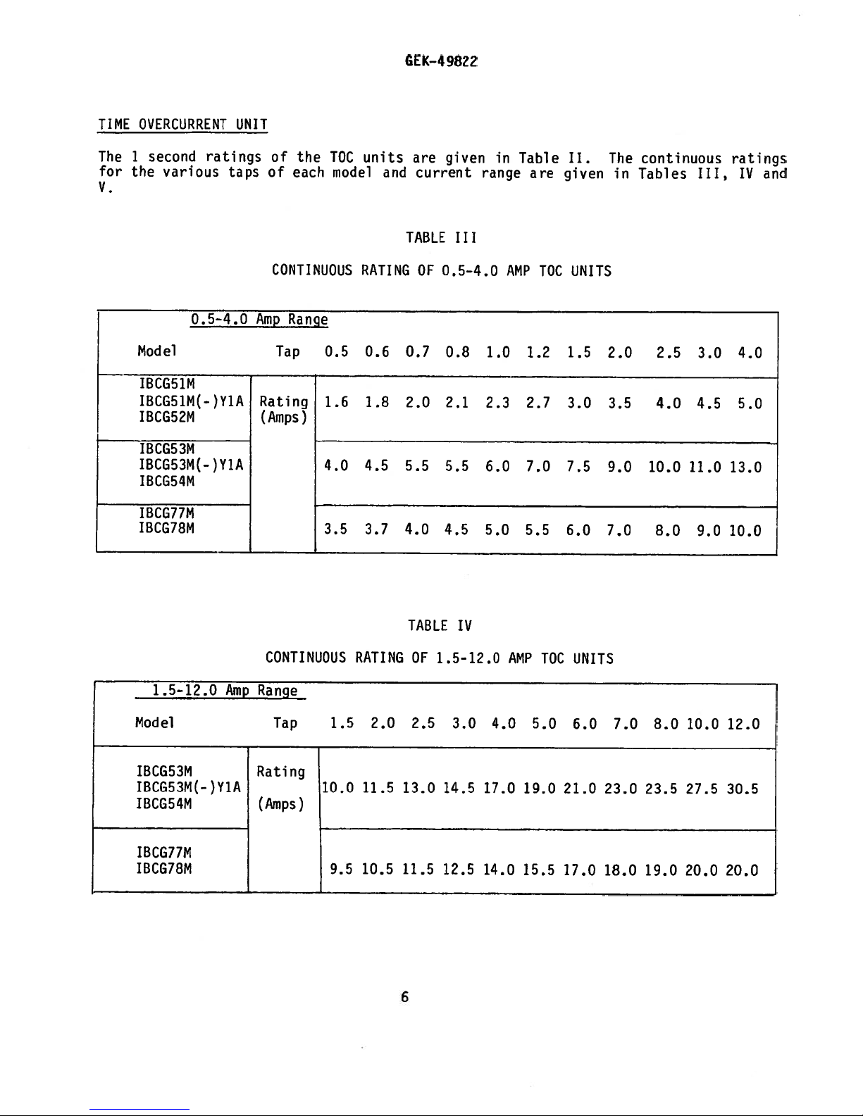
The
for
V.
second
the
Model
IBCG51M
IBCG51M(-)Y1A
IBCG5?M
IBCG53M
IBCG53M(—)Y1A
IBCG54M
IBCG77M
IBCG78M
various
0.5-4.0
ratings
taps
of
the
of
each
CONTINUOUS
Range
Amp
Tap
Rating
(Amps)
TOC
model
0.5
1.6
4.0
3.5
units
and
RATING
0.6
1.8
4.5
3.7
4.0
are
current
TABLE
OF
0.7
2.0
5.5
given
III
0.5-4.0
0.8
2.1
5.5
4.5
in
range
1.0
2.3
6.0
5.0
Table
AMP
2.7
7.0
5.5
are
1.2
TOC
II.
given
UNITS
1.5
3.0
7.5
6.0
The
in
2.0
3.5
9.0
7.0
continuous
Tables
2.5
4.0
10.0
8.0
III,
3.0
4.5
11.0
9.0
ratings
IV
4.0
5.0
13.0
10.0
and
1.5-12.0
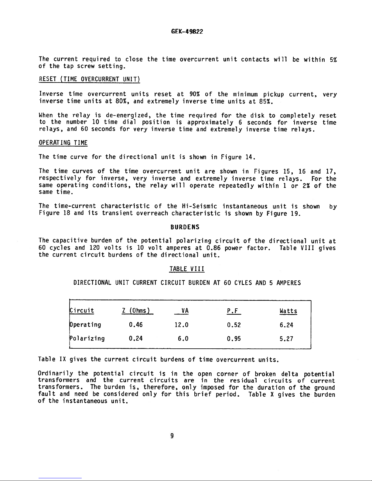
Model
IBCG53M
IBCG53M(-)Y1A
IBCG54M
IBCG77M
IBCG78M
Amp
CONTINUOUS
Range
Tap
Rating
(Amps)
1.5
10.0
r
9.5
RATING
2.0
11.5
10.5
TABLE
OF
2.5
13.0
11.5
6
IV
1.5-12.0
3.0
14.5
12.5
4.0
17.0
14.0
AMP
19.0
15.5
5.0
TOC
UNITS
6.0
21.0
17.0
7.0
23.0
18.0
8.0
23.5
19.0
10.0
27.5
20.0
12.0
30.5
20.0
Page 7

GEK-49822
2-16.0
Amp
Model
IBCG51M
IBCG51M(-)Y1A
IBCG52M
DIRECTIONAL
directional
The
of
5
amperes
The
potential
for
60
UNIT
seconds.
INSTANTANEOUS
Range
unit
anda1
polarizing
UNIT
CONTINUOUS
Tap
2.0
Rating
8.0
(Amps)
9.5
current
second
rating
coils
RATING
2.5
9.0
10.5
polarizing
of
will
TABLE
OF
3.0
10.0
11.5
150
withstand
V
2-16.0
4.0
12.0
12.5
and
amperes.
AMP
5.0
14.0
14.0
operating
120
TOC
6.0
15.0
15.5
volts
UNITS
7.0
16.0
17.0
coils
continuously
8.0
17.5
18.0
have
10.0 12.0
20.0
20.0
19.0 20.0
continuous
a
and
360
16.0
20.0
20.0
rating
volts
instantaneous
The
operation
is
accomplished
the
applicable
range,
mounted
on
either
connect
on
terminal
Instantaneous
Unit
6-150
**
The
28-150.
the
be
sure
rat
i
unit
one
by
the
internal
lead
T
6.
CONTINUOUS
(Amps)
range
There
maximum
to
n
g.
coil
of
positioning
connections
terminal
to
For
approximate,
is
will
setting
L
select
is
two
range
the
the
of
ranges
6
L,
AND
Range
always
and
higher
hinged
(H
of
leads
diagrams
and
reverse
TABLE
SECOND
ONE
L
H
which
be
the
or
L).
T
lead
VI
Range
(Amps)
-
6
-
30
means
least
at
minimum
range,
armature
Selection
and
E
referred
the
to
E
leads
RATINGS
30
150
that
1
H
since
construction
at
terminal
to
auxiliary
and
T
OF
Continuous
Rating
(Amps)
6-30,
ampere
setting.
it
has
in
E.
lOG
10.2
19.6
of
the
Table
UNIT
30-150
overlap
Whenever
the
and
high
See
6.
I.
terminal
One
Second
Rating
(Amps)
may
between
higher
is
or
Table
For
that
260
be
possible,
continuous
tapped
low
the
6—29,
range
VI
H
is
for
and
7
Page 8

GEK-49822
TARGET
The
in
Table
coil.
The
0.2
0.2
up
trip
of
7
tripped.
AND
rating
VII.
DC
RESISTANCE
MIN
OPERATING
CARRY
CARRY
CARRY
60
Hz
ampere
to
coils
ohms
will
SEAL-IN
and
UNIT
impedance
The
+10%
(AMPERES)
CONT.
30
10
(AMPERES)
AMPS
AMPS
FOR
FOR
IMPEDANCE
tap
2.0
is
amperes,
requiring
reduce
tap
(OHMS)
(SEC.)
(sEC.)
(OHMS)
for
at
more
the
of
setting
use
the
than
current
the
seal-in
used
SEAL-IN
+0-25%
with
minimum
2
amperes,
trip
to
unit
will
TABLE
UNIT
coils
control
there
so
low
for
depend
VII
RATINGS
which
voltage.
is
a
value
the
on
0.2
8.3
0.2
0.37
0.05
0.45
50.0
operate
a
possibility
0.2
the
that
and
current
on
If
the
2
ampere
TAP
—
currents
this
that
breaker
drawn
tap
the
taps
by
2.0
0.24
2.0
2.3
2.2
20
0.65
ranging
is
used
resistance
will
are
the
not
given
trip
from
with
be
The
2.0
minimum
maximum
tions
ary
it
relay
should
relay,
may
coil
CONTACTS
The
current-closing
exceeding
the
seal—in
PICKUP
When
the
it
potential
maximum
will
connected
potential
ampere
control
control
be
which
be
necessary
to
250
unit.
torque
pick
up
in
series.
polarization
tap
voltage,
voltage.
arranged
in
allow
volts.
polarized,
angle
at
should
be
provided
If
so
that
turn
energizes
to
connect
enough
rating
Their
current
of
current-carrying
the
of
60°
approximately
The
performance
is
typified
used
with
the
the
tripping
the
induction
the
a
loading
to
operate
the
induction
CHARACTERISTI
directional
lag
(current
0.5
ampere
in
Figure
8
current
trip
of
trip
unit
the
coils
current
unit
coil
resistor
the
unit
rating
Cs
will
lags
with
unit
13.
that
does
exceeds
contacts
or
coils.
in
target
is
is
pick
voltage).
the
with
take
not
exceed
parallel
seal-in
30
amperes
limited
up
operating
simultaneous
30
will
On
by
at
When
and
2
amperes
30
amperes,
operate
such
with
unit.
for
the
3.6
volts-amperes
current
polarizing
amperes
the
an
application,
the
voltages
tap
polarized,
current
or
more
connec
an
auxili
auxiliary
rating
at
coils
at
the
not
of
at
and
Page 9
The
of
current
the
tap
required
screw
setting.
to
close
the
GEK—49822
overcurrent
time
unit
contacts
will
be
within
5%
RESET
(TIME
Inverse
inverse
When
to
relays,
the
time
the
number
and
OPERATING
The
time
The
time
respectively
operating
same
same
time.
The
time-current
Figure
The
60
the
18
capacitive
cycles
current
OVERCURRENT
time
overcurrent
units
relay
is
10
60
seconds
TIME
curve
curves
for
of
for
conditions,
and
its
burden
and
120
circuit
UNIT)
at
80%,
de-energized,
time
dial
for
the
directional
time
the
inverse,
characteristic
transient
of
the
volts
is
burdens
units
and
position
very
overcurrent
very
the
overreach
potential
10
of
reset
extremely
the
inverse
unit
inverse
relay
of
volt
the
amperes
directional
at
90%
inverse
time
required
is
approximately
time
is
shown
unit
and
will operate
the
Hi-Seismic
characteristic
BURDENS
polarizing
of
time
and
extremely
in
are
extremely
at
0.86
unit.
the
minimum
units
for
the
Figure
shown
inverse
repeatedly
instantaneous
is
shown
circuit
power
6
in
of
at
disk
seconds
inverse
14.
Figures
within
by
the
factor.
pickup
85%.
to
time
Figure
directional
completely
for
time
15,
relays.
1
unit
Table
current,
inverse
relays.
16
or
2%
is
shown
19.
VIII
and
For
of
unit
very
reset
time
17,
the
the
by
at
gives
Table
IX
Ordinarily
transformers
transformers.
fault
of
and
the
instantaneous
DIRECTIONAL
Circuit
perating
Polarizing
gives
the
the
potential
and
the
The
need
be
considered
UNIT
current
burden
unit.
(Ohms)
Z
0.46
0.24
circuit
circuit
current
is,
CURRENT
circuits
therefore,
only
TABLE
CIRCUIT
12.0
burdens
is
in
for
this
9
VIII
BURDENAT60
VA
6.0
of
time
the
open
are
in
only
imposed
brief
CYLES
P.F
0.52
0.95
overcurrent
corner
the
residual
for
period.
of
the
AND
broken
duration
Table
units.
circuits
AMPERES
5
Watts
6.24
5.27
delta potential
of
X
gives
of
the
the
current
ground
burden
Page 10

GEK-49822
Time
Characteristic
Inverse
Inverse
Very
Inverse
Inverse
Very
Extr.
Extr.
Inverse
Inverse
**The
The
inversely
for
tap
approximately
+
Some
operate
can
a
CT
purpose.
Calculated
4
impedance
impedance
the
Type
is
22
companies
at
be
made.
secondary
CURRENT
CIRCUIT
Tap
Range
Eff.Res.
(Amps) (Ohms)
0.5/4
2/16
0.5/4
1.5/12
0.5/4
1.5/12
5.60
0.37
1.40
0.23 0.53 0.58
0.80
0.005
values
for
other
approximately
IBCG51M
ohms.
relay,
The
(0.5/1)2
list
minimum
It
pickup.
should
circuit,
from
burden
BURDENS
Burdens
given
taps,
as
impedance
x
22
=
relay
not
since
minimum
at
React.
(Ohms)
21.0
1.44
3.90
1.38
0.147
are
the
0.5/4
5.5
burdens
This
be
TABLE
at
those
at
square
amperes,
ohms.
column
used
the
IX
60
AT
Minimum
**Imped
(Ohms)
22.0
1.49
4.15
1.60
0.17
for
pickup
of
of
the
only
is
in
calculating
burden
pickup.
CYCLESOFTHE
Pickup
+Volt
5.5
5.8
1.0
1.3
0.4
0.4
minimum
P.F.
0.25 10.80
0.25
0.33
0.40
0.50
0.50
Amps
the
current
the
current
the
impedance
ampere
1
as
included
tap,
the
so
volt—ampere
5
amperes
at
UNIT
TOC
Impedance
Ohms
Times
3
Mm
P.U.
0.65
4.20 2.90
0.58 0.36
1.60 1.60
0.17 0.17
tap
of
(tap
rating),
rating.
of
the
at
volt-ampere
direct
a
is
10
Mm
5.00
0.32
each
0.5
ampere,
1
comparison
burdens
used
at
Times
P.U.
relay.
varies
Example:
ampere
input
for
*VA
At
Amperes
555.0
36.3
104.0
14.5
40.0
4.25
is
to
in
this
Fivc
Inst.
Unit
Amps
6-150
Hz
Range
60
Range
Amps
L
H
6-30
30-150
BURDENOFTHE
Mm.
Pickup
Amps
6
30
10
TABLE
X
INSTANTANEOUS
Burden
Pickup
R
0.110
0.022
0.078
0.005
UNIT
Mm
at
(Ohms)
Z
0.135
0.023
3
0.095
0.022
Burden
Times
Pickup
10
0.081
0.022 0.222
Ohms
20
0.079
(Z)
Page 11

GEK-49822
IBCG
type,
of
relays
The
and
directional
its
The
disk
type.
means
overcurrent
The
IBCG
relays
by
Table
The
IBCG
I,
relays
DIRECTIONAL
directional
The
stator
stationary
the
having
central
annular
current-operating,
The
principle
relay
like
higher
resulting
with
a
split-phase
torque
in
CONTACTS
an
closing
unit.
have
UNIT
eight
air
by
wattmetric
a
faster
a
consist
of
instantaneous
unit
contacts,
have
a
target
hinged-armature
a
mounted
are
unit
is
poles
core.
gap
between
current—polarizing
which
torque
element,
induction
and
lower
and
two
is
in
of
projecting
The
rotor
more
CONSTRU
units,
a
power
either
potential
directionally
seal—in
type
the
single-ended
the
induction—cylinder
cuplike
the
poles
and
is
developed
although,
motor.
inertia
sensitive
CTI
ON
overcurrent
time
directional
or
controls
and
unit
models
instantaneous
Mi
inward
aluminum
and
and
induction
the
potential—polarizing
is
the
in
arrangement
The
induction-cylinder
than
unit.
unit
current
drawout
arranged
core.
same
the
unit
(bottom)
polarized
the
with
the
overcurrent
case.
construction
rotor
The
as
that
of
induction-disk
(top)
of
of
the
or
operation
suffix,
ViA
unit.
with
symmetrically
is
free
poles
are
coils.
of
an
parts,
the
construction
the
induction
induction
both
of
the
as
laminated
a
around
to
operate
fitted
induction
unit
provides
construction,
and,
is
cup
by
time
shown
a
in
with
disk
more
The
directional
Figure
effects
low
another,
The
conical
brush
contact
20.
of
gradient
hence,
contact
contact
(E)
brush
Similarly,
the
stationary
contact
contact
dial,
brush
contact.
together
TIME
The
by
OVERCURRENT
inverse
current-operating
coil
coils
flow
coils
operating
is
which
is
act
connected
in
to
disk.
They
vibration.
material
dial
which
on
bears
the
end
functions
retainer
The
stationary
means
time
are
such
produce
unit
of
are
they
resist
(A)
supports
tip
is
against
of
contact
of
a
UNIT
and
coil
to
connected
a
direction
contacts
the
Both
which,
(C).
mounted
the
brush
to
after
mounting
very
wound
taps
a
split-phase
that
low
the
contact
the
The
the
stationary
retainer
stop
the
the
contact
screw
inverse
on
on
the
in
series
as
control
gradient
stationary
when
separation.
stationary
moving
button
a
inner
motion
moving
support
U-magnet
a
tap
to
close
subjected
contact
face
contact
(H).
CL)
time
block.
with
field
the
type,
and
contact
contact
of
of
and
(K)
and
two
overcurrent
iron
a
directional
the
which,
time
specially
moving
to
arm
tip
the
moving
brush
The
the
contact
stationary
and
locknuts
structure.
The
directional
in
overcurrent
constructed
contact
vibration,
brush
supports
(D)
(F).
contact
bears
stop
the
screw
contact
units consist
U-magnet
turn,
(B)
against
arm
contact
(M).
unit
unit
develops
brushes
tend
on
The
(J),
striking
by
dial
The
contains
contact.
contacts,
unit
to
which
the
end
brush
the
mounted
members
tapped
are
minimize
are
to
follow
is
moving
of
the
retainer
inner
are
of
wound
When
the
torque
shown
made
mounted
contact
moving
face
on
the
moving
have
assembled
tapped
a
operating
shading
power
shading
on
in
the
of
one
a
(G).
of
the
made
the
11
Page 12
The
extremely
that
used
structure
One
of
other
is
contacts,
magnetic
unit
contact,
The
disk
touches
spring
to
permanent
variable
compensated
driving
force
in
has
these
a
a
circuit.
shaft
the
give
magnet
retarding
inverse
watthour
two
is
floating
resistor,
the
carries
stationary
the
by
the
as
the
concentric
a
tapped
winding
When
unit
proper
acting
force
spiral
spring
time
overcurrent
meters
current
which
a
capacitor
power
develops
the
moving
contact
contact-closing
on
the
resulting
shape
winds
except
windings
winding
is
flow
is
torque
contact
or
contacts.
disk
of
the
up.
GEK-49822
unit
as
on
connected
and
in
such
on
the
to
produce
from
induction
follows:
the
connected
the
operating
which
current,
the
is
of
middle
in
two
a
direction
completes
The
the
gradient
disk,
the
the
to
series
coils
shaft
and
desired
wattmetric
upper
leg
taps
with
on
as
disk.
is
its
of
which
of
on
the
to
the
restrained
motion
time
the
results
type
portion
the
magnetic
the
the
directional
lower
close
trip
circuit
is
characteristic.
spiral
in
of
tap
legs
a
directional
by
retarded
an
similar
the
circuit.
block;
of
when
a
spiral
spring
increased
iron
unit
by
to
the
the
it
a
The
is
TARGET
A
seal-in
has
its
overcurrent
seal-in
operates,
manually
cover.
INSTANTANEOUS
The
IOC
the
right
obtained
range;
a
predetermined
circuit
until
releases
These
designed
it
handling
promptly
for
relays,
to
any
is
notify
Reasonable
parts
are
SEAL-IN
coil
unit
released
unit
side
by
this
and
it
is
the
protect
damage
evident,
care
injured
UNIT
unit
is
in
unit,
picks
it
raises
UNIT
is
a
of
using
combination
raising
released.
target
when
not
them
sustained
the
nearest
should
or
mounted
series
arranged
up
by
small
the
a
value,
its
of
included
file
be
the
on
the
and
its
in
and
seals—in
a
target
into
pressing
hinged-armature-type
TOC
unit.
tapped
coil
provides
the
instantaneous
target
The
the
into
same
instantaneous
RECEIVING.
as
against
a
in
damage
damage.
transit.
General
exercised
adjustments
left
contacts
such
around
view
the
button
The
which
the
view.
button
part
claim
Electric
in
disturbed.
side
in
a
manner
the
which
located
bC
element
provides
25-to-i
The
that
unit.
HANDLING
of
a
control
Inmiediately
If
at
once
Sales
unpacking
of
the
time
parallel
that
when
main
contacts.
latches
at
instantaneous
operates
a
5-to-i
total
range.
element
target
releases
AND
panel,
upon
injury
or
with
Office.
the
relay
overcurrent
with
the
up
and
the
over
low
operates,
latches
the
STORAGE
will
receipt
damage
the
transportation
in
the
main
When
remains
lower
element
a
range
When
in
target
be
resulting
order
main
contacts
left
and
25-to-i
and
the
closing
the
seal—in
shipped
of
a
that
unit.
contacts
the
seal—in
exposed
corner
is
a
current
its
exposed
relay,
company
none
This
close,
mounted
total
5-to-i
position
unit
in
cartons
examine
from
unit
of
unit
until
of
range
high
reaches
contact
also
rough
and
of
the
the
the
the
on
If
the
original
Foreign
cover
matter
is
cartons
removed,
relays
are
not
in
collected
and
a
cause
to
place
on
be
the
trouble
installed
that
outside
in
immediately,
is
free
the
from
of
the
operation
case
they
moisture,
may
of
the
find
relay.
should
dust
its
be
and
way
stored
metallic
inside
in
chips.
when
their
the
12
Page 13

GEK-49822
Immediately
made
to
ensure
calibrations
readjustment
Since
tests,
these
operating
the
relays.
acceptance
VISUAL
Check
agree
Remove
parts
the
tions
formed
INSPECTION
the
with
the
or
other
shorting
diagrams,
to
nameplate
contact
MECHANICAL
Top
Unit
(TOC)
upon
receipt
that
not
have
is
necessary,
conipanies
following
These
tests,
the
relay
at
requisition.
from
signs
bars
are
Figures
the
INSPECTION
no
damage
been
section
tests
the
discretion
stamping
its
of
physical
in
the
5
shorting
of
the
disturbed.
refer
use
includes
to
case
proper
to
ACCEPTANCE
relay
been
has
to
the
different
be
may
of
ensure
and
check
damage
location(s)
inclusive,
9,
bar.
an
INSPECTION
sustained
the
If
section
procedures
all
applicable
performed
the
user.
that
that
and
TESTS
in
examination
on SERVICING.
for
as
the
model
there
that
all
shown
as
that
and
AND
tests
part
number
are
screws
ACCEPTANCE
shipment
the
or
acceptance
that
the
of
and
broken
no
are
the
main
internal
by
the
and
test
may
rating
or
tight.
brush
TEST
that
indicates
and
installation
performed
be
installation
of
cracked
connec
is
should
the
the
Check
properly
be
relay
that
on
or
relay
molded
that
1.
2.
3.
4.
5.
Bottom
1.
2.
Target
1.
2.
3.
4.
disk
The
disk
The
magnet.
Both
The
position.
The
moving
is
at
Unit
rotating
The
The
contact
and
The
armature
Both
The
target
when
The
contacts
shaft
air
gaps
disk
the
(DIR)
Seal-in
contacts
the
target
end
should
be
should
should
contact
time
0
dial
shaft
should
gap
Unit/Instantaneous
and
contacts
should
should
release
should
play
centered
be
rotate
should
end
make
latch
have
should
free
freely
just
position.
should
play
be
0.015—0.025
should
at
into
button
approximately
be
0.005—0.015
the
foreign
air
in
of
and
touch
be
Unit
move
approximately
view
is
just
operated.
inch.
gaps
of
matter.
should
the
stationary
0.015—0.020
inch
on
the
freely
when
the
as
the
0.030
inch
both
return
inch.
low
operated
same
contacts
wipe.
the
contact
gradient
time.
electromagnet
itself
by
by
make
when
contact.
hand.
and
to
the
should
the
time
and
unlatch
drag
reset
dial
13
Page 14

GEK-49822
DRAWOUT
Since
they
magnetic
relay
plug.
shorting
test
the
external
POWER
All
sinusoidal
the
will
Therefore,
use
freedom
relay;
RELAYS,
all
drawout
tested
be
effects
may
be
tested
This
plug
exercise
bars
allows
plug
in
of
circuitry.
REQUIREMENTS,
alternating—current-operated
waveforms
fundamental
be
affected
in
order
sine
from
wave
harmonics)
a
however,
electromagnets
waveforms.
GENERAL
relays
in
their
of
the
without
makes
the
case.
greater
greater
GENERAL
can
frequency,
by
the
to
of
current
any
relay
(such
as
in
service
cases
or
enclosure will
removing
connections
The
12XLA12A
testing
care,
applied
test
analyzed
be
it
alternating
since
follows
waveform.
and/or
cannot
using
time
be
tuned
overcurrent
operate
an
it
only
flexibility,
connections
devices
as
that
voltage.
expressed
in
equivalent
be
accurately
from
with
plug
test
affected
are
fundamental
a
alternating-current
current
The
as
circuits,
relays)
their
the
the
it
are
relays
purity
a
steel
may
requires
finite
R-L
cases,
duplicated
panel
relay
made
or
is
case.
by
and
also
be
CT
to
by
frequency.
frequency
properly,
of
the
number
RC
networks,
affected
it
using
does
both
(AC)
is
In
during
used.
shorting
the
plus
it
sine
for
by
recommended
this
way,
testing.
12XLA13A
a
not
disturb
Although
jumpers
relay
Since
harmonics
devices
is
wave
any
or
(relays)
essential
(i.e.,
particular
saturating
non—sinusoidal
and
that
any
A
test
any
this
and
the
non—
of
to
its
TARGET
target
The
When
the
0.2
used
minimum
ampere
minimum
The
seal-in
seal-in
take
a
There
will
(undesired)
necessary
adjustment.
time.
Pickup
1.
Connect
ammeter
to
2.
Close
3.
Increase
4.
Open
the
5.
Decrease
AND
control
unit.
screw
and
2.0
picked
SEAL-IN
and
with
control
tap.
tap
from
now
tap
to
Tap
Dropout
relay
and
amperes.
or
jumper
the
the
parallel
the
seal-in
trip
When
voltage,
screw
To
the
be
and
prevent
screws
load
current
up
current
UNIT
unit
coils
voltage,
is
change
left-hand
screws
place
Test
studs
box
the
contact
position.
has
operating
the
trip
the
tap
the
the
in
it
the
should
1
and
so
contact(s)
slowly
slowly
operating
an
the
target
coil
screw
screw
tap
holding
setting,
stationary
both
back
right—hand
never
2
(see
the
that
that
until
circuit
until
on
taps.
in
be
current
the
the
14
currents
and
current
should
the
stationary
allowed
internal
parallel
seal-in
of
seal—in
coil
seal-in
be
the
first
contact
Next,
left—hand
can
step
tapped
ranging
tap
ranges
placed
right-hand
remove
and
remove
contact
remain
to
connections
be
controlled
the
seal-in
unit
2;
the
unit
at
from
screw
from
in
the
place
contact.
picks
seal-in
drops
and
0.2
0.2
2
to
the
2.0
stationary
connecting
it
the
screw
from
in
both
diagram)
unit
up.
unit
out.
to
should
30
ampere
in
This
over
contact.
See
2.0
amperes
the
from
getting
taps
to
should
See
amperes.
2.0
be
tap.
contact
plug.
desired
procedure
at
a
range
a
Table
Table
amperes
in
set
at
of
the
out
the
source,
DC
of
XI.
remain
XI.
at
the
the
the
Then
tap.
other
is
of
same
0.1
in
Page 15

GEK-49822
TIME
Rotate
close
Where
brush
in
its
With
sufficient
ensure
Current
OVERCURRENT
the
time
at
the
0
time—dial
the
contacts
in
or
out
by
support.
the
contacts
gap
between
approximately
Setting
UNIT
dial
means
TARGET
TAP
0.2
2.0
slowly
just
just
the
1/32
setting.
close
of
its
closing
stationary
inch
AND
and
wipe.
SEAL-IN
PICKUP
CURRENT
0.115
1.15
check
can
be
adjusting
at
TABLE
UNIT
-
0.195
-
1.95
by
adjusted
screw.
No.
contact
XI
OPERATING
means
of
by
This
0
time—dial
brush
CURRENTS
DROPOUT
CURRENT
0.05
0.55
a
running
screw
and
OR
OR
lamp
its
MORE
MORE
that
the
should
setting,
metal
the
contacts
stationary
be
held
there
backing
contact
securely
should
strip
just
be
to
The
minimum
determined
block
When
the
procedure
relay
screw
the
connecting
The
minimum
should
time
dial
means
driver
current
This
adjustment
between
Pickup
IBCG53/54
IBCG77/78
means
of
permits
obtained.
closed.
is
marked
tap
must
and
shorts
and
place
be
within
position.
of
the
blade
of
the
adjustment
relays.
relays,
the
any
The
Further
current
by
the
setting
be
plug.
current
spring
in
the
unit
available
variable
desired
control
at
position
in
amperes,
is
followed:
the
it
in
required
5%
of
If
adjusting
the
notches
can
also
tap
by
means
A
different
the
pickup
resistor
setting
spring
adjustment
which
changed
current
the
the
this
be
permits
settings.
the
of
the
as
shown
with
(1)
transformer
tap
marked
to
value
adjustment
ring.
around
brought
any
of
the
procedure
of
the
in
intermediate
is
prewound
of
this
time
plug
in
the
Remove
rotate
marked
the
into
desired
control
unit
the
phase-shifting
setting
15
overcurrent
in
Tables
relay
the
secondary
for
the
the
on
has
The
ring
edge.
agreement
applies
for
between
approximately
the
tap
III,
energized
connecting
desired
disk
the
been
can
By
setting
spring
to
any
current
is
seldom
unit
block.
IV
slowly
tap
disturbed,
be
turning
with
to
applies
the
circuit.
the
will
and
in
plug;
winding.
pickup
and
plate
turned
the
be
IBCG77/78
tap
various
6600
required;
V.
its
for
the
obtained
setting
with
close
The
case,
this
(2)
current.
to
any
it
by
ring,
tap
to
This
tap
if
its
tap
de-energizes
Remove
close
tap
can
be
inserting
setting
intermediately
the
relays.
is
adjustment
settings
the
contacts
it
contacts
plate
the
following
the
(3)
the
contacts
setting
restored
a
the
operating
employed.
IBCG51/52
For
adjusted
is
required,
on
this
the
tap
Replace
and
screw
and
the
also
to
be
just
is
by
by
Page 16

9822
GEK—4
because
necessary
more
it
Test
Connections
shown
and
form
employed
form.
connection
time
the
Setting
Time
setting
The
close
just
closed
travel
maximum
primary
The
time
dial.
along
time,
beyond
of
than
in
The
its
the
time
its
while
the
the
wind
to
900
Figures
constant
testing
in
contact
diagram,
test.
of
contacts
when
maximum
setting.
adjustment
However,
supporting
moving
cutout
insufficient
up
the
notches)
(3
for
making
and
22
frequency.
induction
in
must
time
the
when
dial
the
amount
further
shelf;
it
away
the
in
the
for
control
pickup
23.
the
blocked
be
dial
current
is
to
the
increases
disk.
range
spring
the
from
Use
Stepdown
relays
wound
determines
set
close
time
adjustment
moving
of
and
a
closed
reaches
on
the
of
the
adjuster
factory
time
source
transformers
since
shading
0.
contacts
operation
is
magnet
the
time.
the
variable
setting.
checks
of
their
coil
jumpered
or
the
predetermined
a
When
obtained
more
120
length
the
and
of
toward
Be
resistor,
the
on
volts
or
use
circuit
of
dial
therefore
the
by
sure
than
time
or
phantom
may
for
time
is
unit
moving
the
the
300
over-current
greater
cause
marked
both
the
value.
set
this
is
disk
magnet
it
(1
loads
the
on
made
the
shaft
should
notch)
with
should
distorted
a
see
D,
pickup
unit
The
the
10,
setting
by
permanent
decreases
never
never
or
unit
good
internal
test
requires
contacts
disk
gives
means
extends
unwind
are
wave
not
wave
and
are
must
the
the
of
magnet
the
out
be
be
to
Pickup
rated
Use
contact
the
Set
connection
value
tap
Test
Time
the
Set
connection
relay
should
Test
must
frequency
relay
in
current
relay
in
for
the
to
0.5
22,
be
Figure
closed
at
(1.96—2.04
No.
at
Figure
operate
Relay
IBCG51-IBCG52
23,
within
Type
IBCG53-IBCGS4
both
perform
time-dial
the
time—dial
5
apply
amps).
the
TOC
the
main
limits
UNIT
pickup
the
unit
setting
times
5
OPERATING
Mm.
1.72
1.27
pickup
position
should
tap
given
TABLE
Time
and
and
and
current
in
XII
in
time
time
and
close
the
Table
TIME
Seconds
Midpoint
1.78
1.31
tests.
tests.
ampere
2.0
its
2.0
(10.0
XII.
LIMITS
contacts
amp
amp)
The
tap.
tap.
directional
within
the
to
Max
1.83
1.35
Using
Using
+
relay.
the
2.0%
the
unit
test
of
test
The
18CG77-IBCG78
0.89
16
0.92
0.95
Page 17

GEK-49822
DIRECTIONAL
Current
a.
b.
Polarization
Connect
The
unit
slip
I
This
level
for
too
Potential
a.
Connect
b.
With
between
INSTANTANEOUS
Make
operate.
Whenever
continuous
The
set
core.
counterclockwise
picks
value
sure
instantaneous
the
up.
is
Polarization
V
that
See
possible,
rating.
instantaneous
Turning
obtained.
UNIT
per
between
long
per
set
0.75-1.75
UNIT
the
It
may
Figure
should
8-18
of
a
Figure
for
the
internal
unit
the
increases
be
Once
24
test
close
amperes.
current
period
5
instantaneous
use
unit
necessary
25
volts
amps.
the
has
core
the
of
test
connections
an
to
the
desired
connections.
its
contacts
can
overheat
time.
connections.
at
terminals
higher
adjustable
a
desired
clockwise
pickup.
to
unit
repeat
pickup
within
CAUTION
the
9
is
diagram
range
core
pickup,
decreases
Bring
this
value
to
in
since
5%
coil
10.
the
and
located
loosen
up
the
operation,
is
of
if
the
correct
Table
the
the
current
reached,
0.5
applied
unit
VI.
higher
at
the
pickup;
ampere.
should
range
the
locknut
slowly
until
tighten
too
range
top
The
frequently
close
in
which
of
and
turning
until
the
desired
the
clutch
has
the
locknut.
its
a
unit.
adjust
the
the
or
contacts
it
is
higher
pickup
should
to
To
the
core
unit
F
Refer
instantaneous
the
The
range
position
the
full-clockwise
LOCATION
The
location
well
lighted
to
Table
instantaneous
of
the
of
1/8
of
should
to
facilitate
VI
(p.7)
unit.
unit.
instantaneous
a
turn
position.
be
clean
inspection
Do
of
not
and
for
the
exceed
unit
“full
(see
clockwise”,
INSTALLATION
dry,
and
17
CAUTION
continuous
these
Table
free
from
testing.
and
ratings
VI)
and
dust
must
20
1
second
when
be
turns
and
ratings
applying
obtained
counterclockwise
excessive
of
current
between
vibration
the
to
a
core
from
and
Page 18

MOUNTING
The
relay
diagram
is
should
shown
CONNECTIONS
The
internal
Typical
external
be
mounted
in
connection
wiring
Figure
on
26.
diagrams
diagrams
a
vertical
are
for
GEK-49822
surface.
the
various
shown
by
relays
Figures
The
outline
10,
are
11
and
shown
and
12.
panel
in
drilling
Figures
to
5
9.
Unless
mounted
recomended
conductor
INSPECTION
At
the
time
loose
screws,
corrected
Every
especially
bars
plug
secondary
Before
factory
the
the
adjustments
relay
necessary
contacts.
not
in
circuit
that
or
relay
leaves
to
The
on
that
less
of
or
the
important
the
test
circuits
change
following
a
steel
the
case
than
installation,
other
manner
in
auxiliary
plug
is
put
have
the
factory.
this
panel
be
B&S
1/12
the
imperfections.
described
the
drawout
on
current
brush
before
from
being
into
service,
not
been
setting
tests
are
which
grounded
gage
copper
relay
in
the
be
the
main
opened.
OPERATION
disturbed.
If
the
in
suggested:
adequately
through
should
If
section
CAUTION
case
circuits
bent
high
brushes
it
should
setting
order
wire
has
Refer
a
or
be
any
on
an
and
enough
to Figure
be
The
has
to
grounds
mounting
its
equivalent.
inspected
trouble
SERVICING.
auxiliary
other
do.
time
open
to
given
not
circuits
engage
This
a
dial
been
the
the
for
is
21.
check
will
time
stud
tarnished
found,
brush.
the
will
changed,
relay
or
screw
it
with
be
shorting
connecting
prevent
determine
to
set
overcurrent
case,
It
at
it
it
with
contacts,
should
is
CT
before
0
will
is
a
be
that
be
unit
TARGET
1.
2.
TIME
1.
2.
AND
SEAL-IN
Make
sure
that
Perform
OVERCURRENT
Set
tap
pickup
UNIT
screw
approximately
the
current
This
Check
value
relay
Use
value
the
the
may
must
test
of
operating
be
coordinate.
UNIT
the
and
on
twice
until
current
5
circuit
tap
dropout
desired
tap
the
times
screw
light
should
time
tap
shown
tests
value
at
The
in
is
tap.
be
some
rating
value
Figure
in
as
current
in
within
18
the
outlined
Using
series
multiple
or
the
used
23.
desired
the
until
with
5%
of
maximum
is
of
left
in
test
tap
the
tap.
the
ACCEPTANCE
circuit
contacts
the
contacts
value.
tap
value.
fault
to
the
in
just
begins
This
current
discretion
TEST
Figure
close.
multiple
for
section.
22,
to
which
of
the
apply
Reduce
flicker.
of
user.
tap
the
Page 19

GEK—49822
DIRECTIONAL
Current
a.
Connect
b.
Adjust
UNIT
Polarization
per
the
polarized.
Potential
c.
d.
If
potential
Adjust
from
values
Polarization
the
the
for
INSTANTANEOUS
1.
Select
relay
the
2.
Set
the
(see
higher
the
ACCEPTANCE
Figure
control
polarized,
control
angle
this
of
test.
UNIT
desired
internal
range
since
instantaneous
TEST
section.
24
test
spring
connect
spring
maximum
range
connections
it
unit
PERIODIC
connections.
for
0.5
per
or
7.2
torque.
by
making
diagram).
has
a
higher
to
pick
CHECKS
ampere
Figure
volt
volts
10
the proper
continuous
at
up
ROUTINE
AND
pickup
25
amperes
Whenever
the
if
current
connections.
test
and
(±10%)
0.72
since
amperes
connections
possible,
rating.
desired
current
MAINTENANCE
polarized
the
are
at
the
be
level.
relay
recommended
rear
sure
to
or
is
of
See
dual
6O
the
select
the
In
view
of
is
it
interval
and
enough
important
the
experience
between
users
requirements,
of
from
one
These
original
serviced
TARGET
1.
2.
TIME
1.
tests
settings.
as
AND
Check
Check
OVERCURRENT
Perform
section.
2.
Perform
DIRECTIONAL
Repeat
relay
the
is
connected
the
vital
that
periodic
experience
it
is
two
to
are intended
described
SEAL-IN
the
that
the
that
UNIT
pickup
the
time
UNIT
portion
role
a
periodic
to
select
suggested
years.
If
in
UNIT
unit
unit
test
tests
of
the
in
service.
of
protective
checks
with
the
that
ensure
to
deviations
this
manual.
picks
drops
for
as
up
out
the
described
ACCEPTANCE
test
will
periodic
the
are
at
at
tap
program
vary
test
points
that
encountered,
the
values
25%
in
TEST
relays
be
depending
testing.
interval
the
or
more
service,
the
in
for
in
the
followed.
upon
Until
best
listed
below
relays
the
shown
of
tap
as
OPERATION
the
polarity
operation
environment,
suited
have
relay
in
Table
value.
described
section.
It
is
the
be
checked
not
X.
condition
of
recognized
user
to
deviated
must
in
a
has
his
be
power
type
at
the
for
system,
that
of
accumulated
individual
an
interval
from
retested
OPERATION
which
the
relay
their
and
the
19
Page 20

GEK-49822
INSTANTANEOUS
Check
in
These
that
the
ACCEPTANCE
relays
the
adjustments.
installation
adjustments
suggested
TARGET
AND
Repeat
checks
TIME
Disk
The
which
as
OVERCURRENT
and
jewel
it
purpose.
about
1/64
the
or
outlined
that
SEAL-IN
visual
outlined
Bearings
should
should
The
inch
UNIT
instantaneous
TESTS
adjusted
are
If,
for
periodic
this
work
UNIT
and
in
UNIT
be
be
upper
end
play.
and
any
testing
in
be
mechanical
the
ACCEPTANCE
turned
locked
bearing
unit
the
at
reason,
the
done
up
in
pin
picks
OPERATION
SERVICING
the
factory
they
that
following
in
the
inspections
TESTS
until
this
the
position
should
at
up
sections.
and
have
the
relay
paragraphs
laboratory.
section.
disk
next
be
the
it
been
and
is
by
adjusted
desired
is
disturbed
is
out
the
centered
the
current
advisable
of
should
pickup
set
so
or
limits,
be
in
screw
that
level,
not
it
observed.
and
the
provided
the
to
found
is
the
dropout
air
disk
as
outlined
disturb
checks
gaps,
for
shaft
during
It
current
after
this
the
and
is
has
Contact
The
should
adjusted
adjusting
When
it
correctly
the
and
dial
contacts
the
should
shaft
turn
setting.
Adjustment
should
be
deflected
turning
by
the
time
indicate
adjusted,
just
the
arm
position
dial
Characteristics
Repeat
overcurrent
the
portions
unit.
CHARACTERISTICS
excessive
friction
below
relative
Check
section;
have
about
the
is
on
0
shift
the
and
Also,
caused
about
wipe
the
of
moved
the
time
to
Adjustments
of
check
by
1/32
1/32
inch
adjustment
brush
to
the
time-dial
dial
the
dial.
the
the
ACCEPTANCE
reset
low
reset
worn
a
shaft
inch
when
relative
position
scale.
by
changing
Loosen
until
voltage
voltages
bearing
wipe.
the
screw
to
where
the
TESTS
and
or
disk
the
If
the
screw
the
or
by
That
is,
completes
on
the
brush
it
holds
it
does
position
clamping
contacts
section
time
as
long
mechanical
the
stationary
stationary
stop.
the
not
of
just
that
outlined
reset
interference.
its
contacts
and
the
the
make
apply
under
times
travel.
contact,
the
arm
arm
for
contact
just
brushes
attached
to
zero
0
to
RESET
may
Wipe
thereby
closed,
the
the
in
indicate
tip
is
are
to
shaft
time-
time
the
20
Page 21

On
IBCG77/78
the
as
close
and
current
lower
of
the
1.88
spring
adjusting
by
contacts
check
should
limit,
disk.
to
until
relays,
are
possible
as
the
check
2.1?
compensation
the
current
be
This
amp
resistor.
just
within
that
is
limits,
set
open.
to
required
called
the
relay
Adjust
2.0
amps.
the
limits
movement
a
the
at
No.
Recheck
GEK-49822
the
on
pickup
Then
to
just
1.88
is
not
compensation
following
time
10
compensation
move
move
over
steps
dial
2
within
to
check.
amp
the
the
2.12
1/2
is
tap
the
time
disk
amps.
inch,
should
within
after
with
If
the
limits
dial
away
measured
the
be
taken:
limits.
the
resistor
1.96
to
from
If
the
current
time
the
the
dial
to
No.
stop
disk
along
falls
reset
Then
adjustment.
set
2.04
10
moves
the
outside
the
restore
so
amps,
position
arm.
at
periphery
control
pickup
that
but
This
the
the
DIRECTIONAL
L3eari
nqs
The
lower
end
about
To
down
until
Cup
Should
of
check
on
the
and
the
1/64
the
the
Stator
it
following
All
leads
reconnecting.
still
The
attached.
upper
removed.
expose
removed,
assembly
dust
and
this
and
and
metallic
UNIT
jewel
threaded
inch
clearance
contact
strikes
cup
necessary
be
procedure
the
to
The
the
of
On
some
screw.
the
exposes
bearing
end
unit
unit
three
models,
entire
particles
core
play
arm
the
should
should
The
the
should
support.
in
the
between
near
iron.
remove
to
be
followed:
first
can
then
flat—head
it
may
four
corner
top
structure
stator
until
be
screwed
shaft.
the
the
shaft,
The
the
be
screws
be
assembly,
the
The
iron
core
shaft
cup—type
be
disconnected
removed
holding
necessary
screws
lifted
unit
all
upper
thus
should
from
clamping
which
is
reassembled.
the
bearing
and
the
depressing
move
rotor
the
the
to
off.
should
way
inside
from
and
cradle
unit
remove
the
This
in
should
about
tagged
a
unit
be
until
of
the
1/16
the
with
the
to
resistor
together
gives
protected
its
head
be
adjusted
the
rotor
spring-mounted
inch.
directional
for
identification
its
mounting
plate
or
should
capacitor
should
access
keep
to
engages
to
cup,
unit,
next
to
the
it
allow
press
jewel
plate
now
the
the
in
be
to
be
cup
from
To
remove
of
top
side
molding.
Contact
To
make
contact
the
the
of
the
The
Adjustments
contact
parts
shaft
molded
shaft
must
rotor
adjustments,
and
proceed
and
be
contact
must
rotor
pulled
be
as
from
arm.
handled
refer
follows:
out
the
and
The
very
to
21
contact
the
shaft
carefully
Figure
head
clutch
and
20
assembly,
adjusting
cup
while
for
screw
can
now
it
is
out
identification
the
be
spring
taken
pulled
of
the
of
clip
unit.
low
out
out
at
of
of
gradient
the
the
the
Page 22

GEK-49822
Loosen
at
the
backstop
the
tension
required
the
inner
windup
the
arm
contact
inward
the
mounting
contact
stationary
stationary
moving
contact
the
locknut
tension
fully
Bias
Connect
jumper
directional
terminals
wiped
Torque
the
front
screw
at
face
sprocket
pointing
mounting
until
brush
contact
contact
wipe.
on
the
across
9
locknut
right
so
that
of
each
the
contact
of
until
directly
screw
the
stationary
screw
retainer.
contact
brush
Tighten
which
the
stationary
in,
there
Adjustment
current
terminals
unit
and
10
which
hand
the
low
its
respective
the
to
until
members
stop
retainer.
the
secures
is
operating
5
spiral
jumpered.
secures
corner
gradient
tip
forward.
the
screw,
the
approximately
and
spring
moving
in
moving
stationary
and
the
Wind
again
locknut.
contact
and
8.
of
order
moving
stationary
and
backstop
the
the
contact
contact
to
brush
contact
Loosen
the
just
advance
Unwind
brush
current
Apply
so
that
moving
directional
arm
brush
cause
retainer.
arm
contact
contact
backstop
begin
the
Unwind
screw
such
an
equal
polarizing
current
contact
is
the
is
the
contact
to
this
screw
the
that,
the
unit)
permitted
that
so
end
Adjust
in
locknut
support.
members
stop
screw
touch.
screw
1
backstop
its
to
deflection
terminals
to
unit
stop
of
neutral
a
inward
arid
support.
when
coils
picks
(backstop)
to
1-to-?
the
the
which
just
lines
Loosen
until
screw
the
on
in
its
to
Wind
a
up
support.
swing
grams
brush
spiral
position,
secures
begin
up
until
it
half
2/3
contacts
each
series
and
4
at
to
the
to
with
the
the
just
turns
turn
Finally,
brush.
7
0.5
screw
freely.
of
pressure
separate
spring
the
mounting
touch.
the
moving
locknut
touches
to
and
adjust
are
connecting
by
and
adjust
ampere
(located
Unwind
Adjust
with
i.e.,
stationary
screw
Unwind
moving
of
provide
tighten
made
the
are
from
the
with
and
the
the
the
and
a
the
with
The
core
to
minimize
produced
other
but
may
Short
polarizing
operating
If
the
which
nut
on
bearing
reti
ghtened.
Keep
in
long.
sufficient
Clutch
The
connections
the
clutch
current
of
by
any
two
circuits
be
checked
out
the
coil
coil
unit
causes
the
underside
screw.
mind
Therefore,
time
Adjustment
adjustment.
in
the
the
the
potential
(terminals
does
it
that
between
shown
range
directional
effect
one
of
de-energized.
by
observing
(terminals
not
to
do
This
amperes
30
leave
in
of
of
the
polarizing
4
satisfy
so.
of
the
screw
the
tests
Figure
The
5
unit
bias
operating
7
and
the
The
relay
should
will
test
for
fixed
to
25
has
torques
The
that
and
and
5)
core
cause
current
the
for
24
amperes.
a
or
adjustment
the
coil
8)
check
above
can
and
be
coils
the
resistor
small
produced
polarizing
responds
unit
(terminals
unshorted.
that
conditions,
be
turned
turning
held
the
securely
current
on
to
polarity
should
A
screw
flat
only
cool.
on
of
the
the
portion,
the
rotor.
quantities
the
core
as
and
9
Supply
unit
rotate
loosening
by
core
in
coils
for
short
check
be
capable
projecting
the
is
outlined
10),
30
does
the
by
position
to
overheat
can
purpose
Such
acting
made
leaving
amperes
not
core
the
means
intervals
also
of
from
torques
alone
at
below:
operate.
to
large
of
when
if
be
used
controlling
the
of
the
the
through
a
hexagonal
the
the
left
and
in
side
which
can
with
factory,
current
position
slotted
nut
on
allow
making
of
is
be
the
the
is
too
the
the
22
Page 23

GEK-49822
moving
phase
less
setting,
intended
contact
with
of
the
suddenly
10—15
assure
to
INSTANTANEOUS
1.
Both
contacts
2.
The
backing
the
molded
3.
WIth
should
the
half
contacts
Contact
For
consists
in
effect
are
flexibility
Fine
cloth.
of
the
abrasive
the
contacts.
of
Cleaning
cleaning
left,
silver
Knives
contacts.
material
be
of
a
yet
armature
in
the
should
fine
a
superfine
of
contacts
arm
voltage.
amperes,
UNIT
should
strip
strip
a
Check
shaded
silver
flexible
corroded
the
or
files
Abrasive
in
controls
applied
is
that
the
close
should
under
against
horizontal
this
pole
close
with
strip
file.
tool
ensures
should
may
the
contacts,
the
Adjust
current,
tighter
acceptance
at
be
the
armature.
plane
by
and
the
contacts,
of
The
material
not
leave
paper
clutch
the
the
so
the
inserting
the
feeler
metal
polishing
the
be
or
pressure.
clutch
but
than
test
same
formed
pole
and
armature
a
flexible
with
will
cleaning
cleaned
scratches
cloth
thus
preventing
will
the
time.
that
piece,
there
a
gage
be
may
so
that
slip
8—18
limits
the
should
0.010
with
in
burnishing
an
action
removed
of
with
which
leave
Use
ampere
will
the
inch
place.
etched
the
knives,
increase
contact
rated
it
will
at
forked
cross
be
the
roughened
is
so
rapidly
actual
minute
frequency
not
or
above
acceptance
be
met
end
member
at
least
feeler
armature
tool
delicate
points
files
arcing
particles
closing.
slip
in
(front)
gage
should
and
or
and
at
15
amperes.
test
any
future
of
the
1/64
between
held
be
surface,
that
thoroughly.
contact.
of
abrasive
and
deterioration
of
current
10
amperes
limit
bears
‘T”
inch
the
closed.
used.
resembling
scratches
no
Insulating
and
tests.
against
spring
wipe
paper
in
or
This
is
on
front
The
This
The
or
The
burnishing
It
Is
enable
When
ordering
Electric
nameplate
on
which
Since
the
recorTlended
the
prompt
Company,
data.
the
relay
last
edition,
tool
that
replacement
renewal
specify
If
was
described
sufficient
parts,
possible,
furnished.
Figure
above
of
quantity
give
26
can
quantities
any
address
required,
the
Refer
has
obtained
be
RENEWAL
that
are
the
General
to
renewal
been
changed.
PARTS
of
renewal
worn,
nearest
name
Electric
from
broken
of
parts
parts
Sales
part
the
factory.
be
or
damaged.
Office
wanted,
Company
publication
carried
of
and
give
requisition
GEF-4083.
in
the
stock
General
complete
number
to
23
Page 24

GEK—49322
ovacunhNl
Figure
1
(8043458)
Type
IBCG51M(-)y1A
in
its
Case
24
(Front
or
View)
the
IBCGS3M(-)ylA
Relay
Page 25

GEK-49822
TOG
STATIONARY
CONTACT
TARGET/SEAL-IN
ADJUSTING
LOCKING
SCREW
PICKUP
RING
RING
ADJUSTING
TOC
TAP
SCREW
1.
TOC
TAP
BLOCK
/
TOC
MOVING
I_TOG
—INSTANTANEOUS
_TOC
‘—DIRECTIONAL
PICKUP
RING
DISK
UPPER
LOCKING
PIVOT
SCREW
CONTACT
ADJUSTING
UNIT
UNIT:
AND
GRADIENT
LO
CONTACT
DIRECTIONAL
CUP
UNIT
Figure
2
(8043459)
Type
Removed
IBCGS1M(-)Y1A
Case
from
(Front
25
or
i—CLUTCH
SCREW
‘.._CONTACT
IBCG53M(-)Y1A
the
View)
MOVING
ADJUSTING
STOP
CONTACT
SCREW
Relay
Page 26

THYRFrE
DISK
GEK-49822
Figure
3
(8043450)
Type
Removed
IBCG51M(-)yJA
from
Case
(Rear
26
or
the
IBCG53M(-)yJA
View)
____c
2
Relay
Page 27

C4_________
TOC
RESISTOR
THYRITE
DISK_—
GEK-49822
rd
Figure
4
(8043461)
from
Type
IBCG77M
Case
(Rear
27
IBCG78M
or
View)
Relay
Removed
C
2
Page 28

WOUND
0
L_______
[
<L
SHADING
TCC
COILS
TOC
GEK—49822
I
I
C2
0
POT.
POL.
51=
TOC
D
SEAL-tN
=
TIME
=
DIRECTIONAL
OVERCURRENT
Figure
*
‘1
UNIT
UNIT
5
(0269A3061-O)
UNIT
113CG53M
T
internal
Relays
28
Connections
(Front
*SHORT
View)
for
FINGER
IBCG5IM
I
and
Page 29

GE
K-
49822
11
TOC
vouNn
HADINt,
CCIL
TOC
CIJ
OP
L
CI
PI
P3
‘C2
D
P
OT
POL.
IN5TANTANEOUS
I=
=SEAL-IN
SI
=
TOC
TINE
=
DIRECTIONAL
0
Figure
6
UNIT
OVERCUIRENT
(0269A3062-O)
2
UNIT
UNIT
UNIT
Internal
IBCG53M(—)Y1A
4
Connections
Relays
29
6
(Front
=
IBCG51M(-)Y1A
for
View)
8
5HGRT
FINGER
and
Page 30

GEK-49822
r
L
ICC
-]
WOUND
IN
J
Al
D
<i
I
(Ol[
Hi
L
D
1
t)
U
foc
p3
p4
D
p
o.
>
10L.
I
NIT
SI
—SEAL
TOC
—TIME
[)—PIRFTIONL
IN
OVEkCI.
Figure
kENT
JNJT
(0273A9194-0)
7
IBCG52M(—)A
I
NIT
and
4
SHORT
Diagram
(Front
Internal
the
IBCG54M(-)A
*
Connections
Relays
30
I
FINGER
for
View)
the
Page 31

dia’
11
TOC
WOUND
S
H
U
COIL’
GEK—49822
IN
Ts1
TOC
D
CURR. POL.
TH
YRIT
P3
p4
D
POT.
P
CL.
C
SI
=SEAL-IN
TO
Figure
TIME
C
DIRECTIONAL
0
8
(0269A3063-O)
UNIT
OvERcuFRENT
UNIT
Internal
UNIT
Connections
31
q
G
FINGER
(Front
View)
for
*
IBCG77M
SHORT
Relay
Page 32

GEK-49822
Cl
P2
D
P1
C2
D
FOL.
Sl=SEAL-IN
TOC=TIME
UNIT
OVERCURF?ENT
D=DIR[CTIONAL
9
Figure
(0127A9424-O)
UNIT
UNFT
IBCG78M(—)A
Internal
Relay
Connections
(Front
32
View)
=SHORT
Diagram
FINGLR
for
the
Page 33

GE
K—49822
1
2
PHASE
SBUECE
1—2—3
OR
3—2-1
3
z
0
fr
LLu
Lu
U)
6V5
D
USED
A
D
IS
IF
POTENTIAL
IS
USED,
&
B
TO
I
21
3
POLARIZATION
I
CONNECT
IF
NOT
TO
C.
C
CURRE2T
USED,
STUD
POLARIZATION
CONNECT
IF
TO
POLARIZATION
DO
7
&
A
POTENTIAL
IS
NOT
1).
NOT
CONNECT
.
TO
B
c
67N-IBcG51M
TOC—TIME
D—DIRECTIONAL
T&S1..TARGET
Figure
LEflE2D
53M
OVCURRE21T
AND
UNIT
AND
SE&L—IN-tJNfl’
10
(0273A9051—0)
for
77M
UNIT
Relay
Typical
Types
External
IBCG51M
2
33
53M
a
52
r
Connections
or
77M
2Ii
ST
52
Diagram
Page 34

GEK—49822
—b
Q
L
clL.
—ft
NOTES
IF
POTENTIAL
I.
CONNECT
POLARIZATION
PHASE
PHASE
RELAYS
I
1A
POLARIZATION
ATOD
AND
IS
NOT
SEQUENCE
TOC
D
IS
IF
BTOC.
POTENTIAL
USED CONNECT
I—2-30R
USED
Dt
CTOD
3-2-I
67N
SEE
S
7
NOTE
67N
D
2
3
>4:
-J
w
cr
4:
B
0
C
I
SEE
NOTE
2
IF
2.
CURRENT
DO
NOT
CONNECT
67N-IBCG5IMC-)Y
BC
C,
I
)3
D—DIRECTIONAL
INSTANTANEOUS
I-
TOC-TIME
POLARIZATION
TO
STUDS
IA
hi
C-)
Y
IA
OVERCURRNT
Figure
11
(0273A9052-O)
for
UNIT
UNIT
Relay
IS
NOT
7ANO8
UNIT
Type
USED
2
TRIP
Typical
IBCG5IM(-)Y1A
External
34
7N
TSI
£7N
TOC
or
j7N
SI
21
Connection
53M(—)Y1A
G7N
T’
3j
Diagram
Page 35

GEK-
49822
3—2—1
1
2
PHASE
SEQUENCE
1—2—3
OR
—
3
z
C)
I-I
C-)
1
•1
321
1VJ
PCTU.TIA1,
IF’
O)ARIAT3O?
CCNTLTCDJTCC.
POTENTIAL
IF
?OT
IS
t’SFJ)
IS
POT
C(1iCT
USED,
ITICJ
D
67
91
C
TO
D
8
CURRENT
IF
NCTI
IS
CONNECT
POLARIZATION
USED,
TO
DO
STUDS
OT
7
7&8
UuL
67N
TO
TRANSFORM
NEUTRAL
C’)
r;1
POWER
ER
LJEND
67N__1EcG52M
1
53(,
IOC.-ThSTANTANEOUS
TOC-TII1E
D-DIRECTIONAL
T&STTARGET
Figure
OVERCURRENT
UNIT
&
SEAL
(275A4559—O)
12
78M
OVCURR2’lT
UNIT
114
UNIT
External
and
the
urr
78M
35
Diagram
Relays
1
J67N
La
3
j52
for
I
the
T&SI
TOC
a
TC
IBCG52M,
J--Li
21
L
3T
STOC
SI
54M
Page 36

GEK-49822
4
1.
o
L3
F
W
a-
—1
.8
“
r
c
x
-j
0
.6
,
o
F
c_,
a,
.4
0
.2
0
0
0
0
m
,--
o
Figure
0
0
0
j—
O
SEC.
—
of
Type
0
OHMS
of
Local
IBCG
Current,
0
jr
IMPEDENCE
Comparison
Effect
Unit
of
Typical
A
C1
SOURCE
Showing
—
(300
0
0
0
13
(0362A0684—1)
or
Dual
Impedance
O’o
0-.
0
LOCAL
Polarization
Directional
on
GROUND
t’I
Ground
Relay
C,
tO
0
C
t
Potential
‘0
36
Page 37

GEK—4
9822
85
80
75
70
—-----
60
55
50
=
-*-[-
45
;
40
35
EEEE±E+S
‘-
30
25
20
15
5
0
-\
I I
I
IF
POTENTIAL
MULTIPLES
IF
CURRENT
MULTIPLES
IF
DUAL
POLARIZED
MULTIPLES
9
ANGLEBYWHICH
=
ANGLEBYWHICH
Ep:
POLARIZING
I
POLARIZING
:zIr:::tn::z:*
r-
0
cO
c
.o
cn
,—I
MULTIPLES
crc
0
—
C-.
OF
POLARIZED
OF
PRODUCT
POLARIZED
OF
PRODUCT
OF
PRODUCT
VOLTAGE
CURRENT
0
cO
PRODUCT
I
0
s
PICKUP
I
I
P1CX-UP
PICK—UP
PICK
LAGS
0
LAGS
I
CURRENT
0 0
0
-crc
-o
LIL
—
:
UP
‘p
000
c—
cO
EI0c0s
i0ICos
E
0.25
I—60)
3.6
——
--
Ca
I
19—60)
3.6
0
0
(fl
0
(N
.1
-
I
ICOS$
0
0.2
0
0
0
rc
0
0 0
00
0
)
Cl
i-
Cc
C)
0
0
c
Z
0
00
.—
t
Figure
14
(0376A0934—O)
Directional
Time
Unit
Characteristic
of
Type
37
IBCG
of
Relay
Dual
Polarized
Page 38

86
g0e0
III
I
I
I
I
I
I
I
Dill
00
00
00
00
•’
DI
0
:141100
11111
11411
11—0
11:41
I
40
-
7
31
OR-Cl
0’
0000
]1A
ot-or-o;o
rS.0.OOi..I
0
Iii
I
).$-j
Jill
NIl
IO111
000
I
I
.
IV
i011’1IOhOC
707011
0110
00
10O0LO9O
01
ViI0flIy
111l1
ill)
0bOE,
01
01
Ill
‘il0flHI1HO
01
J10111i:JrOv
Mi
I.’
:[E=
(5
0
in
z
In
-I
\
I
EE
EEE
1::z
0I
6
8L
C
V
1±
H,
lb
C’,
0
EEE
:
::
-
EEEE
:
I-
-tIL±tltt::
.
z
I{]iFEE
0
z
m
-i
‘I
II
3
-4
ID
I.
.4
‘a
liii
C
n6ij
0
0
II
IL
DC
Or
S31dl11fll4
JO
00
0.
(E-69o888o)
WLj
AV93
BE
-
toI0I
—
d1I
9NLLI3S
UeJaflD-aLuhj
UJJflD.aAO
4Ufl
SiJa.DPJ.I43
D
JO
SAUI
Page 39

GEK-4982
2
[X1FCF[
L
.
20
2.,3.0.
0.2.5.
3.0.
2.
F(1
tIU
TIE
S.0.0.Ci.
4.0.
.0.0.0.C.0.7.D.8.C
FPIF)
(f?CC
TIS
T
7.0.
IC.
12
.0,
10.0,12,16
.DJLS
CONTI
WIN
NL0LiSY
-
I
Figure
16
(088880270—3)
MULTIPLES
Inverse
OF
RELAY
Time-current
Time
Overcurrent
39
TAP
SETTING
Characterisitc
Unit
of
Very
Page 40

GEK-49822
1811111
4
1
INS
.INI
5
2
11IIII
F
I
IT.
I”
0.
5-4.
2-Il
10-00
70-110
\‘
\\
IFITI
UNIT
0
11111
11111
be
III
4-
w
7-
IC.
I.
7•
a
L.j
z
bJ
601
I
161
‘-“.0
0.
1.5-12.0
2
C.
‘I
C.
U
C.
21
II
(EUC
2.5,
PPN(F
TAPO
0816
11441
5.0,6.0,7.0,8.0,
4.0,
3.0
FXT[)EFL
Q.A,O.6,D.7,0.BI.0I.2,I.2.0.2.S,3.l2,4.0
,
2.0,
I.
7.0.2.5,3.0.1.0.5.06.0,7.0.8.0,
FFIE)
0.0,12.
2OIlII
I
M
f
I
AIIJUSfl4[NTS
INST
0611
SLY
TI
111100
CON
ABLE
2
IC,
S
I
ADJUST
Nil
7-
1C.
.4
P1
z
P1
:
::
.3--
.1”
Ii
.07
9•
::
C1
82
.11
.8
:
=:::
::
=
El::
—
of
—-
—
—
—
--
--
—
—
—
--
-
.-
—
---
—
—
-
-
—
Extreme’y
--
—
---
—
--
-
11
F
—
C.
C.
i7
—
II
I.
-
C.
Ci
-
ui.
I
-.
=
——-ttN-tl14\-
=
:
:t
HNUN
:11flE
s
{11
.
-
5
2
H*ffii1’
‘3
-
-
—
-
—
Figure
3I
1
4
17
-
-
-
—
—
—
III
ii
MULTIPLES
(088880274—5)
Inverse
(I
18I4)3II.
88
OF
RELAY
Time-current
Time
———-
In
—
0’
——---
C
——---
—
Dl
-—-—---
U,
—
0
——---
0
—
Dl
E
—
I
TAP
Overcurrent
—
—
—
—
—
—
-
—
—
—
-.
—
SETTING
Characteristic
-
—
—
-
—
—
-
-
-
-
-
-
-
-
-
Unit
——
—
——
--
—--
—
——
—
——
—
40
Page 41

GEK-
49822
0
U
0
cf
Ui
-J
0
‘1
Figure
18
(0208A8695’)
Hi_Seismic
TimeCUrrent
InstantaneoUs
41
CharaCter1st1
Unit
of
L)
the
Page 42

I—
U)
LU
fuJ
cj
LU
—
—
LU
U)
GEK-49822
(!1
-J
U)
LU
LU
U-i
LU
-J
(3
19
Figure
(0208A8694-2)
of
1N33èi3d
the
NI
Transient
Hi—Seismic
I-OYd]AO
Instantaneous
42
Overreach
Characteristics
Unit
Page 43

GEK—49822
L
-
Contact
A
-
Stationary
B
C-Contact
H—Stationary
Dial
Tip
K
Contact
Contact
Brush
Brush
—
Retainer
J-Stop
Screw
K-Stationary
L—Mounting
M—Locknuts
Contact
Screw
Support
-
Moving
D
E-Moving
Figure
Contact
Contact
20
Arm
Brush
(8027688
Assembly
and
for
F
G
8023399)
Directional
the
43
Button
-
Moving
(
Low
I’-,
L
Contact
Contact
Gradient
Unit
Tip
Brush
F
E
Retainer
Contact
Page 44

BLOCK
CONNECTING
BRUSH
MAIN
PLUG
BAR
BL
CONNECTING
TERMINAL
SHORTING
BRUSH
I
AUXILIARY
BRUSH
ON
BRUSH
MAIN
THE
ENGAGING
BEFORE
PLUG
BLOCK
ENGAGING
AUXILIARY
INCH
1/4
TERMINAL
CONNECTING
NQTE:AFTER
-n
cQ
co
CD
ci,
C)
o
o-.
-f,
0
-+
—
>c
‘0
-
0
‘-S
D
THE
TRAVELS
(1
:,-
0
Page 45

ADJ.
GEK--49822
RES.
ThN.
-.
—..
*
1
3
5
7
9
•
2
4
6
TYPE
XLA13
TEST
PLUG
Figure
22
(0195A9179-O)
Test
Connections
45
for
Checking
Pickup
of
TOC
Unit
Page 46

TOT1)4ER
“STOP”
GEK—49822
oNi—
I
ADJ.
R.
--
RATED
1
—-‘i,
2
TYPE
1LA13
3
TEST
PLUG
5
6
7
S
TO
Tll4
“START”
9
10,
Figure
23
(0195A9180-O)
Operating
Test
Time
46
Connections
of
TOC
Unit
for
Checking
Page 47

ADJ
•
GEK—49822
RES.
I
(5-k_EQ
120
V
RATED
-
TYPE
XLA13
1
2
TEST
PLUG
4
6
8
10
Figure
24
(0195A9181-1)
Directional
Test
Unit
Connections
using
Current
47
for
Checking
Polarization
Pickup
of
Page 48

GEK—4
9822
TYPE
XLA13
TEST
PLUG
I
120V
RATED
(0195A9182-O)
Figure
25
Directional
Unit
Test
using
Connections
Potential
48
Checking
for
Polarization
Pickup
of
Page 49

GEK—49822
______
____
15.
125
384MM
1/4
6
HOLES
6MM
5.
132MM
375
1
0.
264MM
.218
5MM
FOR
TYPICAL
INCHES
MM
6
-.—
.
168MM
GLASS
[
DRILL
H-
187
1I
PANEL
SEMI-FLUSH
DRILLING
FRONT
DIM.
625
1
125
29MM
CU
TtI
.
687
5
144MM
MOUNTING
VIEW
—
UI
12843
7MM
•J
PANEL
VIEW
FOR
SEMI
-
7,406
186MM
L
1
CASL
SHOWING
SURFACE
PAN[L
-FLUSH
6)
MTG.
157MM
14,812
376MM
5MM
LOCATION
10—32
SCREWS
5/8
DRILL
4
HOLES
16MM44MM
8.312
6,l906
J
175MM
18MM
76MM
ASSEMBLY
MTG.
ON
SURFACE
X
3/8
211MM
10
0
OF
STEEL
(4)
FOR
1
0—32
STUDS
3.0
76MM
3
M
HHLoI
5.25
1
33MM
DRILL
HOLES
19MM
5/16-18
HARDWARE
PANELS
5/16—18
SURFACE
1
4
365MM
CUTOUT
500
I
PANEL
FOR
STUD
375
00000
10
BACK
DRILLED
/
4.156
1
sir-I
DRILLING
SURFACE
FRONT
STUDS
MTG.
STUD
NUMBERING
97531
00000
8
6
4
VIEW
NAY
REPLACE
HOLES
06MM
7
185MM
468
500
12MM
I
(TYPICAL)
MOUNTING
VIEW
2
281
Figure
26
(K-6209273
[51)
Outline
Type
and
IBCG
49
Panel
Relays
Drilling
Dimensions
for
Page 50

0
GE
Power
215
Anderson
Markham,
Canada
Tel:
(905)
Fax:
(905)
www.ge.comlindsyslpm
Management
Avenue
Ontario
L6E
1B3
294-6222
201-2098
 Loading...