

Page 1
INSERT
GE
BOOKLET
I-28824B
GEH-1814
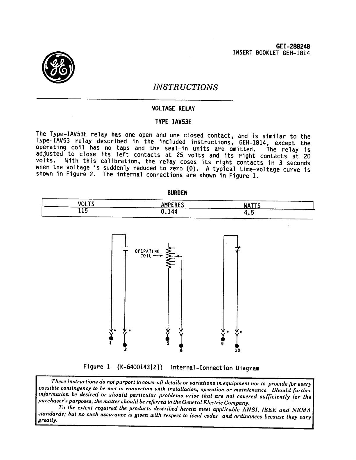
The
Type-IAV53E
Type-1AV53
operating
adjusted
volts.
when
the
shown
in
relay
coil
to
With
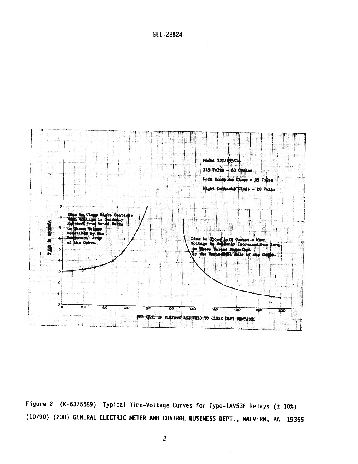
voltage
Figure
relay
has
close
this
2.
VOLTS
115
described
no
its
caHbration,
is
suddenly
The
has
taps
left
internal
one
in
and
contacts
reduced
•
OPERATING
JNSTR
VOLTAGE
TYPE
open
the
the
the
connections
COIL
IAV53E
and
one
included
seal-in
at
relay
to
zero
BURDEN
AMPERES
0.144
UCTJONS
RELAY
closed
instructions,
units
25
volts
coses
(0).
are
its
shown
contact,
are
and
right
A
typical
its
in
-J
and
GEH-1814,
omitted.
right
contacts
time—voltage
Figure
WATTS
4.5
-
is
1.
similar
except
The
contacts
in
relay
3
curve
to
the
the
at
seconds
is
20
is
These
possihie
information
purchaser’s
To
standards:
greatly
Figure
instructions
contingency
desired
he
purposes,
the
extent
no
hut
tobemet
the
required
such
#..
1
do
not
or
should
matter
assurance
(K-6400143[21)
purport
in
should
the
cover
to
connection
particular
he
products
is
given
referred
all
with
problems
described
with
respect
1
Internal-Connection
details
or
installation,
arise
to
the
General
herein
to
variations
operation
that
Electric
meet
local
codes
ø.O.
in
equipment
or
are
not
Company.
applicable
and
Diagram
nor
maintenance.
covered
ANSI,
ordinances
to
provide
Should
sufficiently
IEEE
and
because
for
further
for
NEMA
they
every
the
vary
Page 2
GEI-28824
—
l
I.—
1
L
I’
-i:
‘..T;it.:
—
—
———i——
.1
4
1O
I
—
&O
——
-_
Wfl
—————
—
it&
QO$TACZ2
Figure
(10/90)
2
(K—6315689)
(200)
GENERAL
Typical
ELECTRIC
Time-Voltage
METER
AND
Curves
CONTROL
2
for
Type-IAV53L
BUSINESS
DEPT..,
Relays
MALVERN,
(±
PA
10%)
19355
Page 3
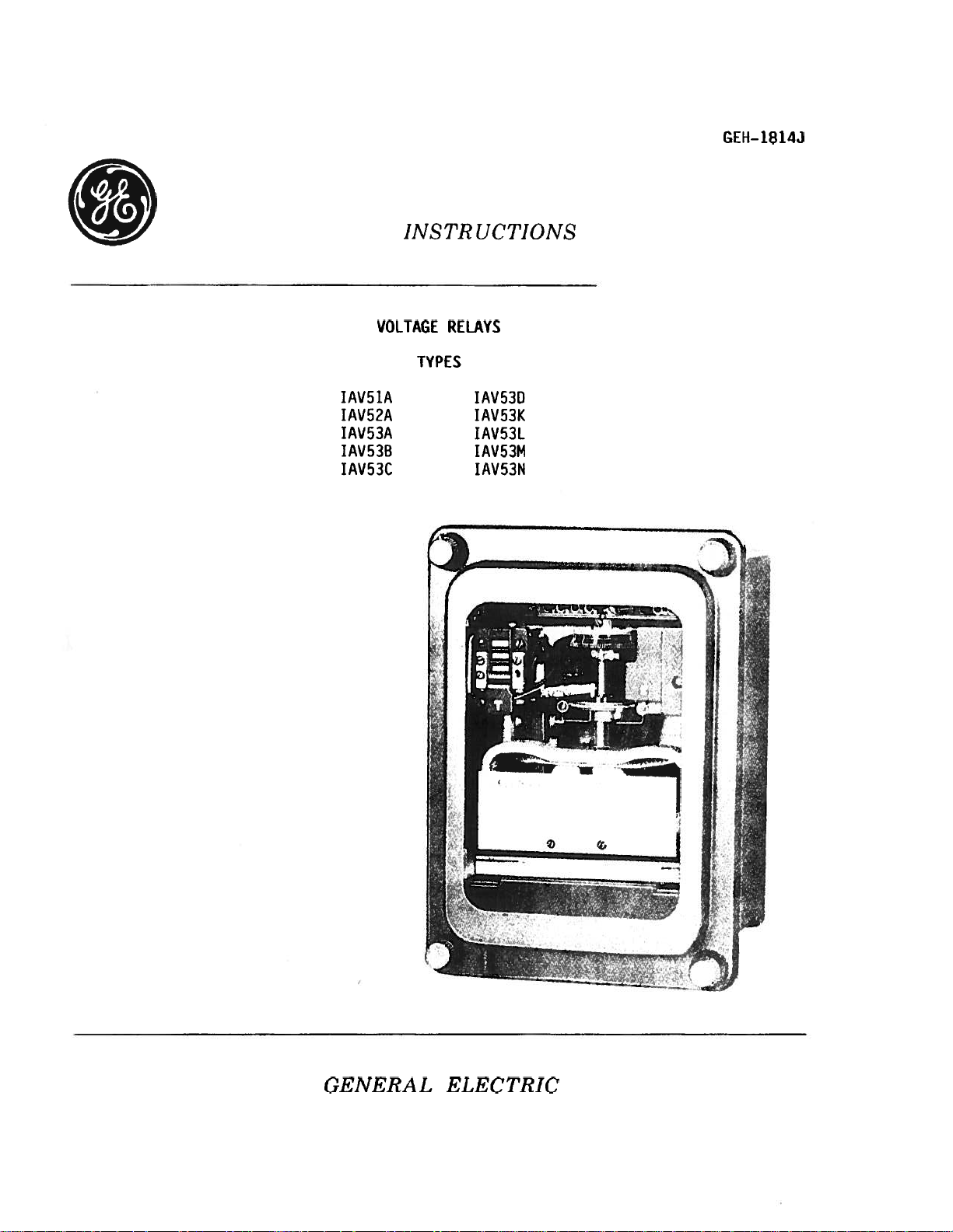
GEH-
1814J
VOLTAGE
IAV51A
IAV52A
IAV53A
I
AV53B
IAV53C
JNSTR
RELAYS
TYPES
(ICTIONS
1AV530
IAV53K
IAV53L
IAV53M
IAV53N
GENERAL
ELECTRIC
Page 4
GEH-1814
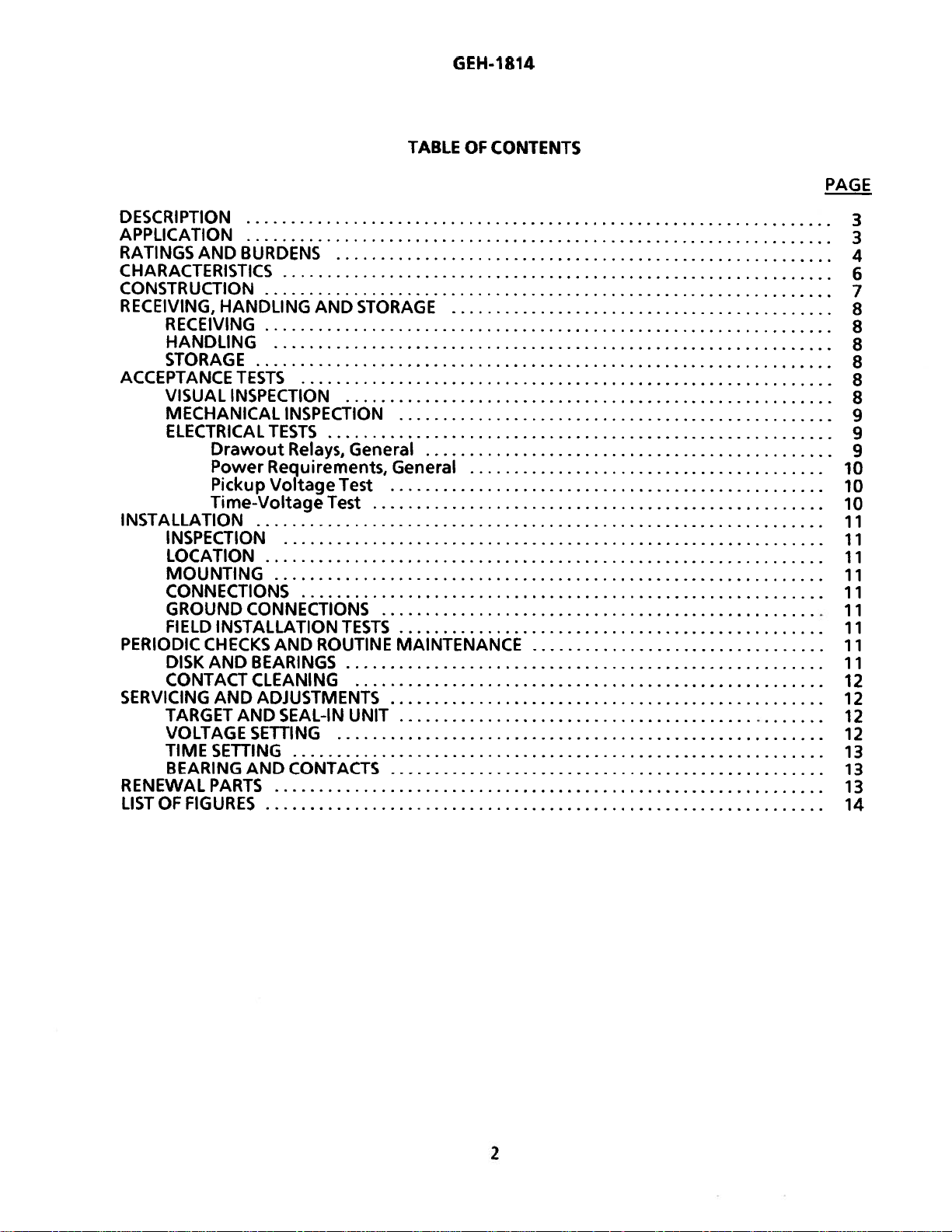
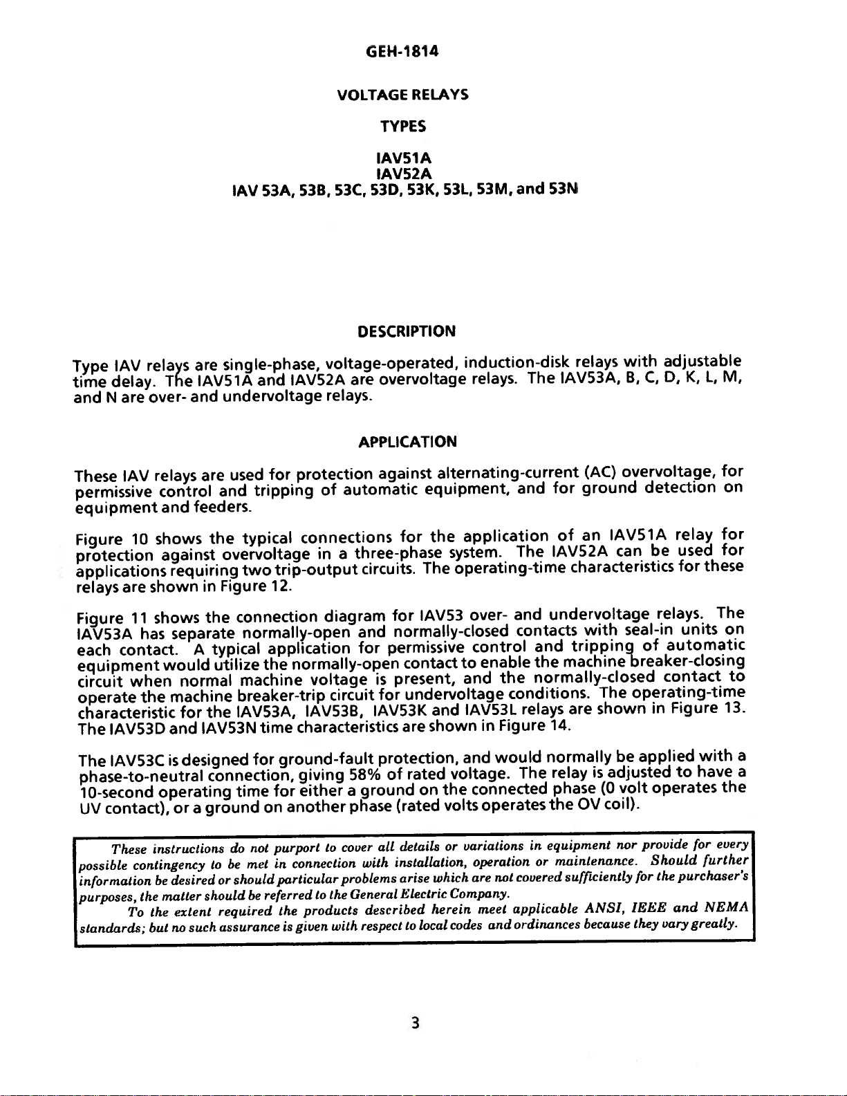
DESCRIPTION
APPLICATION
RATINGSANDBURDENS
CHARACTERISTICS
CONSTRUCTION
RECEIVING,
RECEIVING
HANDLING
STORAGE
ACCEPTANCE
VISUAL
MECHANICAL
ELECTRICAL
INSTALLATION
INSPECTION
LOCATION
MOUNTING
CONNECTIONS
GROUND
FIELD
PERIODIC
DISKANDBEARINGS
CONTACTCLEANING
SERVICINGANDADJUSTMENTS
TARGETANDSEAL-lN
VOLTAGE
TIME
BEARINGANDCONTACTS
RENEWAL
LISTOFFIGURES
HANDLING
TESTS
INSPECTION
Drawout
PowerRequirements,General
Pickup
Time-Voltage
CONNECTIONS
INSTALLATION
CHECKS
SETTING
SETTING
PARTS
AND
INSPECTION
TESTS
Relays,
VoltageTest
Test
AND
ROUTINE
General
TESTS
UNIT
TABLE
STORAGE
MAINTENANCE
OF
CONTENTS
PAGE
3
3
4
6
7
8
8
8
8
8
8
9
9
9
10
10
10
11
11
11
11
11
11
11
11
11
12
12
12
12
13
13
13
14
2
Page 5
GEH-t
814
and
These
IAV
delay.
are
N
IAV
Type
time
permissive
equipment
relays
The
over-
relays
control
and
single-phase,
are
IAVS1A
undervoltage
and
are
and
feeders.
IAV
used
53A,
IAV52A
and
for
tripping
VOLTAGE
53B,
53C,
DESCRIPTION
voltage-operated,
are
relays.
APPLICATION
protection
of
automatic
RELAYS
TYPES
IAV51A
IAV52A
53K,
53D,
overvoltage
against
equipment,
and
53M,
531,
induction-disk
relays.
The
alternating-current
and
53N
relays
IAV53A,
(AC)
for
ground
with
adjustable
D,K,L,
C,
B,
overvoltage,
detection
M,
for
on
shows
Figure
protection
10
against
applications
shown
relays
Figure
IAV53A
each
equipment
circuit
operate
are
1
shows
1
has
contact.
when
the
would
characteristic
The
IAV53D
The
IAV53C
phase-to-neutral
10-second
contact),
UV
These
possible
information
purposes,
standards;
operating
instructions
contingency
be
matter
the
the
To
but
the
requiring
in
the
separate
typical
A
utilize
normal
machine
the
for
and
IAV53N
is
designed
connection,
or
ground
a
to
desired
should
extent
such
no
typical
overvoltage
trip-output
two
Figure
12.
connection
normally-open
application
the
machine
breaker-trip
IAV53A,
time
for
for
time
on
purport
not
do
met
referred
be
in
particular
be
or
should
required
assurance
connections
a
in
diagram
normally-open
voltage
circuit
IAV53B,
characteristics
ground-fault
giving
either
another
cover
to
connection
problems
the
to
products
the
with
given
is
for
three-phase
circuits.
for
normally-closed
and
permissive
for
present,
is
for
IAVS3K
are
protection,
of
58%
ground
a
phase
General
(rated
alt
installation,
with
described
respect
details
arise
Electric
application
the
system.
operating-time
The
1AV53
over-
control
contact
to
and
undervoltage
IAVS3L
and
shown
and
on
voltage.
connected
the
rated
volts
variations
or
operation
are
which
Company.
herein
codes
local
to
and
enable
the
conditions.
Figure
in
would
operates
not
applicable
meet
ordinances
and
an
of
The
IAV52A
characteristics
undervoltage
contacts
and
the
with
tripping
machine
normally-closed
relays
are
14.
normally
relay
The
phase
OV
the
equipment
in
maintenance.
or
covered
sufficiently
ANSI,
because
IAVS1A
can
seal-in
of
breaker-closing
operating-time
The
shown
applied
be
adjusted
is
volt
(0
coil).
provide
nor
for
IEEE
they
relay
used
be
for
relays.
units
automatic
contact
Figure
in
to
operates
for
Should
purchaser’s
the
and
vary
greatly.
these
The
with
have
every
further
NEMA
for
for
on
to
13.
a
a
the
3
Page 6
GE
H-I
814
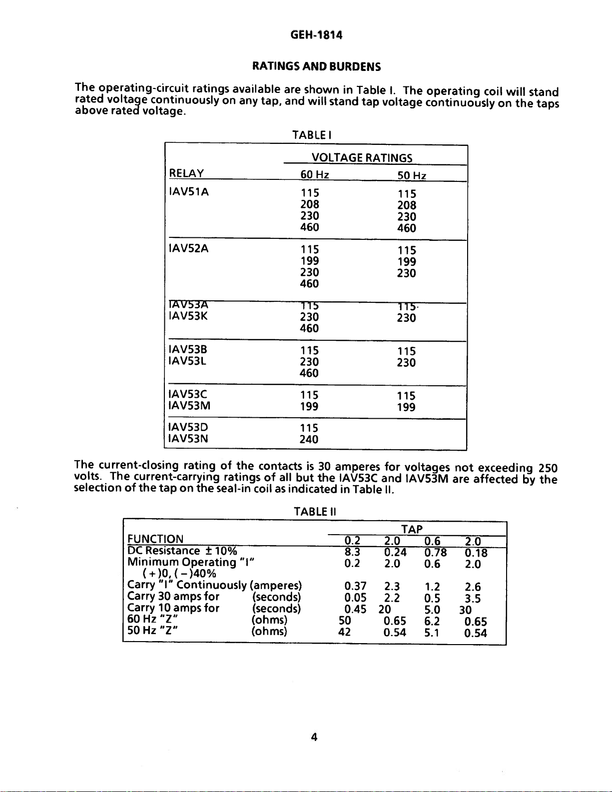
The
operating-circuit
rated
above
voltage
rated
continuously
voltage.
RELAY
IAV51A
IAV52A
IAV5A
IAV53K
IAV53B
IAV53L
ratings
avaIabIe
on
any
RATINGS
are
tap,
and
TABLE
AND
BURDENS
shown
will
stand
I
VOLTAGE
60Hz
115
208
230
460
115
199
230
460
115
230
460
115
230
460
in
Table
tap
I.
The
voltage
RATINGS
50Hz
115
208
230
460
115
199
230
115
230
115
230
operating
continuously
coil
on
will
the
stand
taps
The
current-closing
volts.
The
selection
IAVS3C
IAVS3M
IAV53D
IAV53N
rating
current-carrying
of
the
tap
on
FUNCTION
DC
Resistance
Minimum
Carry
Operating
“I”
Continuously
Carry3oampsfor
Carry
60
50
lOampsfor
Hz
‘1”
Hz
‘7”
the
±
10%
of
the
ratings
seal-in
contacts
of
coil
“I”
(amperes)
(seconds)
(seconds)
(ohms)
(ohms)
all
as
indicated
TABLE
115
199
115
240
but
is
30
the
amperes
IAV53C
in
Table
II
02
8.3
0.2
0.37
0.05
0.45
50
42
for
and
II.
2.0
0.24
2.0
2.3
2.2
20
0.65
0.54
115
199
voltages
IAV53M
TAP
0.6
0.78
0.6
1.2
0.5
5.0
6.2
5.1
not
are
0.18
2.0
2.6
3.5
30
0.65
0.54
exceeding
affected
2.0
by
250
the
4
Page 7
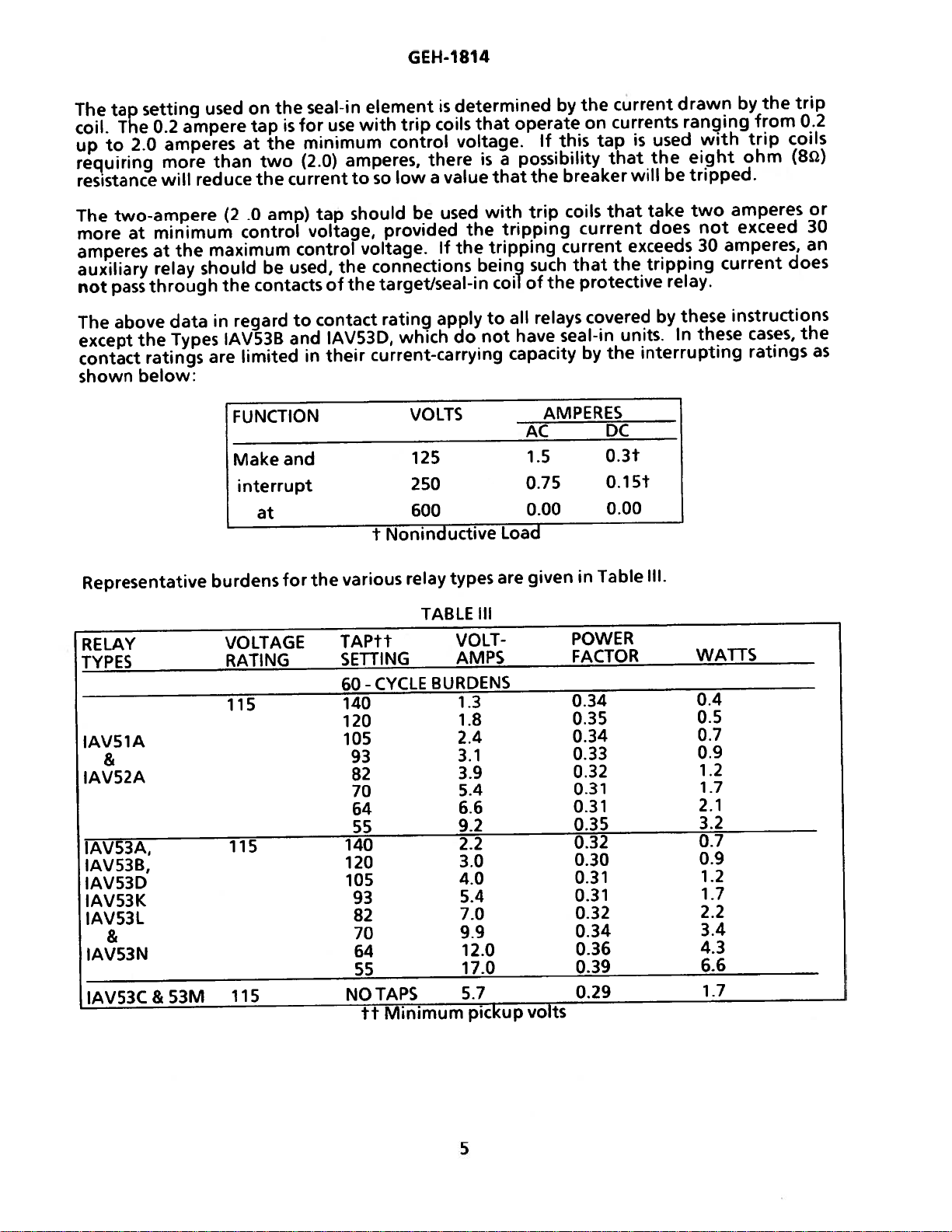
The
tap
The
coil.
to
up
requiring
resistance
setting
0.2
2.0
ampere
amperes
more
reduce
will
used
than
at
on
tap
the
the
two
the
is
for
minimum
(2.0)
current
seal-in
use
element
with
control
amperes,
low
so
to
GEH-1814
determined
is
coils
trip
voltage.
there
value
a
by
operate
that
If
this
isapossibility
the
that
breaker
the
on
current
currents
tap
that
is
will
used
the
be
drawn
ranging
with
eight
tripped.
by
trip
ohm
the
from
trip
0.2
coils
(8Q)
two-ampere
The
minimum
more
amperes
auxiliary
not
The
except
contact
shown
at
pass
above
at
relay
through
the
ratings
below:
Representative
RELAY
TYPES
IAV51A
&
IAV52A
IAV53A,
IAV53B,
IAV53D
IAV53K
IAV53L
&
IAV53N
IAV53C
&
the
data
Types
53M
.0
(2
control
maximum
should
the
in
regard
IAV53B
are
limited
FUNCTION
Makeand
interrupt
burdens
VOLTAGE
RATING
115
115
115
amp)
control
used,
be
contacts
to
and
at
for
tap
voltage,
the
of
contact
IAV53D,
their
in
various
the
TAPtf
SETTING
60
140
120
105
140
120
105
NO
should
be
provided
voltage.
connections
target/seal-in
the
rating
which
current-carrying
VOLTS
125
250
600
f
Noninductive
relay
TABLE
CYCLE
-
93
82
70
64
55
93
82
70
64
55
TAPS
Minimum
tt
with
used
tripping
the
the
tripping
If
being
coil
do
to
not
apply
Load
types
are
III
VOLTAMPS
BURDENS
1.3
1.8
2.4
3.1
3.9
5.4
6.6
9.2
2.2
3.0
4.0
5.4
7.0
9.9
12.0
17.0
5.7
pickup
trip
such
of
the
all
relays
have
capacity
AMPERES
AC
1.5
0.75
0.00
given
volts
coils
current
current
that
protective
covered
seal-in
by
DC
0.3t
0.1Sf
0.00
in
Table
POWER
FACTOR
0.34
0.35
0.34
0.33
0.32
0.31
0.31
0.35
0.32
0.30
0.31
0.31
0.32
0.34
0.36
0.39
0.29
that
exceeds
the
units.
interrupting
the
take
does
tripping
relay.
these
by
In
Ill.
amperes
two
not
30
amperes,
current
instructions
these
WATTS
0.4
0.5
0.7
0.9
1.2
1.7
2.1
3.2
0.7
0.9
1.2
1.7
2.2
3.4
4.3
6.6
1.7
exceed
cases,
ratings
or
30
an
does
the
as
5
Page 8
GEH-1
814
RELAY
TYPES
IAV51A
&
IAVS2A
IAV53A,
1AV538,
)AV53D
IAVS3K
IAVS3L
&
IAVS3N
IAV53C&53M
VOLTAGE
RATING
115
115
115
TABLE
TAPtt
SETTING
50-
CYCLE
140
120
105
93
82
70
64
55
140
120
105
93
82
70
64
55
NOTAPS
ft
Minimum
III
(continued)
VOLTAMPS
BURDENS
2.1
2.8
16
5.1
6.2
8.2
2.5
3.4
4.6
6.0
8.4
12.9
13.2
4.8
pickup
12
1.6
1.9
volts
POWER
FACTOR
0.34
0.34
0.34
0.38
0.36
0.34
0.34
0.34
0.32
0.30
0.29
0.31
0.32
0.35
0.29
0.35
0.32
WATTS
0.4
0.5
0.7
1.9
1.3
1.7
2.1
2.9
0.6
0.8
1.0
1.4
1.9
2.9
3.7
4.6
1.6
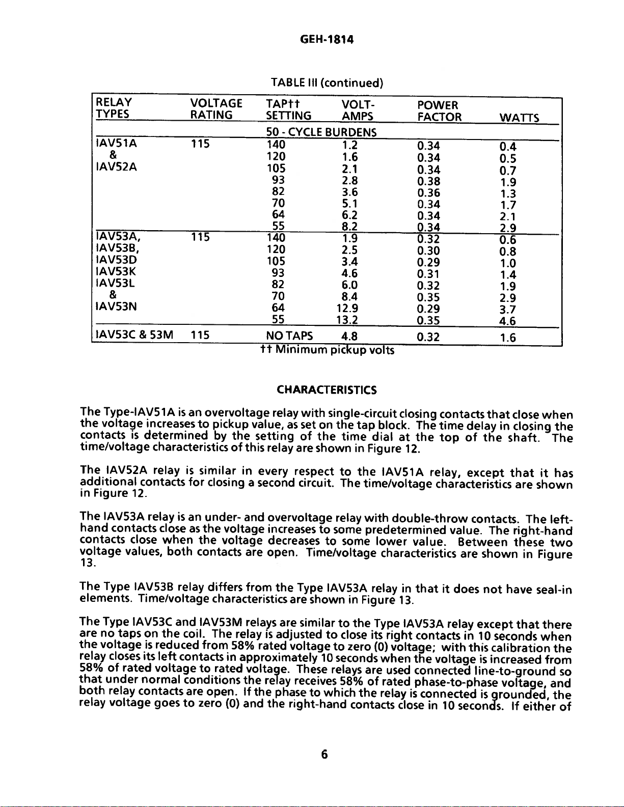
The
Type-IAV51A
the
voltage
contacts
time/voltage
The
IAV52A
additional
Figure
in
The
IAV53A
hand
contacts
contacts
voltage
values,
13.
The
Type
elements.
The
Type
are
no
taps
the
voltage
relay
closes
58%
of
rated
that
under
both
relay
relay
voltage
increases
determined
is
characteristics
relay
contacts
12.
relay
close
close
when
both
IAV53B
Time/voltage
IAV53C
on
is
its
and
the
reduced
left
voltage
normal
contacts
goes
is
an
overvoltage
pickup
to
by
similar
is
for
closing
isanunder-
as
the
voltage
the
voltage
contacts
relay
differs
characteristics
IAV53M
coil.
The
from
contacts
to
in
rated
conditions
are
open.
to
zero
(0)
CHARACTERISTICS
relay
value,
the
setting
of
this
relay
in
every
second
a
and
overvoltage
increases
decreases
are
open.
from
the
relays
relay
58%
is
rated
are
adjusted
approximately
voltage.
the
relay
If
the
phase
and
the
with
as
set
on
of
the
are
shown
respect
circuit.
to
to
Time/voltage
Type
are
shown
similar
voltage
10
These
receives
which
to
right-hand
single-circuit
the
time
to
The
relay
some
some
IAV53A
to
to
close
to
zero
block.
tap
dial
in
Figure
the
time/voltage
with
predetermined
lower
relay
in
Figure
the
Type
its
(0)
seconds
relays
58%
are
of
the
contacts
closing
The
at
the
12.
IAV51A
relay,
characteristics
double-throw
value.
characteristics
in
that
13
IAV53A
right
contacts
voltage;
when
relay
used
rated
the
voltage
connected
phase-to-phase
is
connected
close
in
contacts
time
delay
top
of
except
value.
Between
are
it
does
relay
in
with
this
10
seconds.
that
close
in
closing
the
shaft.
that
are
contacts.
The
The
right-hand
these
shown
not
except
10
in
have
that
seconds
calibration
is
increased
line-to-ground
voltage,
grounded,
is
If
either
when
the
The
it
has
shown
left-
two
Figure
seal-in
there
when
the
from
so
and
the
of
6
Page 9

other
the
left-hand
The
contacts
IAV53D
Time/voltage
phases
two
is
relay
characteristics
close
similar
are
grounded,
in
approximately
to
are
the
Type
shown
GEH-1814
relay
the
10
1AV538
Figure
in
voltage
seconds.
relay
14.
increases
except
that
the
shorter
a
voltage
rated
to
has
it
time
and
curve.
Type
The
IAV53N
While
to
the
double-end
operating
breaker
the
relay
causes
in
the
completed.
11
and
10
These
relays
operating
completes
shaft
disk
motion
There
isaseal-in
models,
main
the
in.
seals
remains
cover.
IAV53K
IAV53D.
IAV53A,B,C,
case,
connected
coils
the
if
reset
the
to
relay
internal
See
external
for
are
on
coil
trip
the
restrained
is
retarded
is
shown
as
contacts,
When
the
exposed
is
similar
&
with
connecting
position,
pick
connections.
the
of
laminated
a
alarm
or
by
permanent
by
mounted
unit
Figure
in
such
seal-in
released
until
Type
the
to
are
D
contacts
to
single-end
in
connected
both
plugs
circuit-opening
i.e.,
both
up;
connections
induction-disk
U-magnet.
circuit
spiral
a
spring
magnets
to
This
15.
when
that
picks
unit
by
IAVS3A,
cases,
between
purpose
removed
are
must
Figures
The
be
-
1
blocks.
plugs
CONSTRUCTION
construction.
disk
The
touches
to
it
give
when
acting
the
of
left
the
its
contacts
raises
button
a
coil
has
unit
main
the
up,
pressing
it
IAV53L
the
and
contacts
place
in
for
8
shaft
the
proper
the
the
on
shaft
in
target
a
to
IAVS3B,
IAV53K,
upper
the
this
of
subsequently
closed.
before
coil
and
disk
The
carries
stationary
contact-closing
disk
to
all
of
close,
and
the
series
into
beneath
IAV53M
M,
L,
and
is
to
Insertion
the
contact
is
actuated
the
contact
give
the
but
contacts
its
seal-in
view,
lower-left
the
N
and
lower
avoid
reinserted
contact
circuits,
moving
correct
the
IAV53B,
which
to
relays
false
of
by
contact,
or
voltage,
in
unit
latches
IAVS3C
are
blocks
tripping
with
either
circuits
and
potential
a
contacts.
time
L
D,
parallel
picks
corner
and
the
in
and
of
the
plug
are
Figures
which
The
and
delay.
and
with
and
up
and
up
the
of
its
M
case
The
hardware
reset
sealing
The
only
mechanism
wire.
case
(IAV51
connections
contact
removable
a
fingers
completes
external
relay
The
with
unit,
latch
by
a
cradles
are
connecting
of
by
To
cradle
the
thumbscrews,
draw
connecting
is
suitable
provided
is
when
studs
has
52A,
and
between
mounted
connecting
circuits.
the
connections,
mechanism
leads
all
top
the
at
constructed
so
and
besides
case,
plug,
holds
cradle
the
out
can
plug
for
screw
or
being
and
either
for
either
one
IAV53A,
and
relay
the
in
plug
The
the
and
mounted
is
terminated
bottom
making
also
the
from
drawn
be
surface
mounting.
required.
is
connections
units
stationary
(two
outer
inner
in
and
the
that
the
the
locks
connecting
a
single-ended
out.
or
8,
C,
and
molded
plugs
blocks,
blocks
steel
a
at
by
relay
electrical
latch
In
semi-flush
The
Two
both
at
D)
and
the
for
attached
have
framework
inner
the
guide
a
cannot
in
place.
in
plug
case,
so
doing,
7
panel
cover
the
of
(IAVS3K,
ends
for
the
studs
case
and
inner
IAV53K,
the
terminals
the
block.
pin
at
inserted
be
connections
The
place.
cover
the
the
mounting
attaches
cover
external
are
outer
the
to
called
This
the
cover,
trip
to
screws
L.
connections.
made
blocks,
L,
case,
for
the
cradle
back
the
in
between
which
must
circuit
the
M,
M,
the
cradle
of
first
is
and
case,
have
N)
or
through
between
and
have
internal
held
is
case.
the
case
the
fastened
is
removed.
be
first
an
assortment
and
provision
or
at
The
spring-backed
N
models)
studs
the
connections.
is
and
firmly
The
upside
respective
opened,
carries
bottom
the
electrical
which
complete
a
in
the
cases
down.
the
to
Then
then
for
nests
for
blocks
of
the
a
that
the
case
and
The
case
the
the
Page 10
GEH-1
814
voltage
can
should
The
be
released
be
cradle
circuits
connecting
RECEIVING
These
relays,
designed
examination
handling
company,
HANDLING
Reasonable
are
damaged
STORAGE
are
followed.
can
be
plugs
when
to
protect
should
is
evident,
and
the
care
nor
opened.
and
drawn
must
not
be
nearest
should
the
After
the
cradle
out
from
be
drawn
RECEIVING,
shipped
them
a
against
made
damage
for
General
be
exercised
adjustments
the
easily
a
double-ended
out
first.
as
a
damage.
any
damage
claim
Electric
in
disturbed.
connecting
drawn
out.
HANDLING
part
of
a
Immediately
sustained
should
Sales
be
Office
unpacking
plug
To
case
AND
control
filed
the
has
been
replace
in
the
STORAGE
panel,
upon
during
at
once
should
relay
be
in
removed,
the
cradle,
same
will
receipt
shipment.
with
notified
order
way,
be
that
the
the
except
shipped
of
the
If
injury
the
transportation
promptly.
none
lower
reverse
that
in
relay,
or
of
the
latch
order
two
cartons
an
rough
parts
If
the
relays
cartons
in
Immediately
made
to
calibrations
If
no
pickup
blocks,
plug
one
used
of
the
is
set
the
if
the
required
VISUAL
Check
relay
INSPECTION
the
agree
Every
current
bent
high
brushes
are
a
place
upon
make
have
value
relay
in
the
taps,
value
pickup.
nameplate
with
circuit
circuits,
enough
do.
not
that
receipt
sure
that
not
for
is
shipped
tap
corresponding
the
tap
is
half
the
requisition.
in
the
and
This
will
to
be
is
free
of
no
been
disturbed.
the
left
with
plug
way
stamping
drawout
other
to
engage
prevent
installed
from
the
damage
contact
the
is
put
between
the
case
circuits
ct
immediately,
moisture,
dust,
ACCEPTANCE
relay
tap
to
in
make
an
INSPECTION
has
been
is
specified
plug
this
value.
the
tap
two
taps)
sure
in
CAUTION
has
an
auxiliary
with
shorting
the
connecting
secondary
circuits
they
and
TESTS
sustained
on
the
If
a
nearest
and
that
plug
should
metallic
and
the
requisition
fifth
tap.
specified
the
the
the
model
brush.
bars,
or
from
be
stored
chips.
ACCEPTANCE
in
shipment
for
If
pickup
value
required
spring
does
value
is
adjusted
number
It
is
especially
that
the
auxiliary
test
plug
being
open.
and
the
is
specified,
not
and
important
before
in
TEST
that
relays
coincide
(the
to
their
should
lower
obtain
rating
brush
the
original
the
with
the
tap
of
on
be
main
be
relay
tap
tap
with
is
the
the
8
Page 11
GEH-1814
Remove
or
other
bars
the
signs
areinthe
relay
MECHANICAL
1.
On
relays
factory.
the
all
2.
On
tight.
relays
These
subjected
The
3.
moving
stationary
stationary
the
The
the
Any
and
stop-arm
molded
foreign
either
4.
5.
position of
End
so
top
great
and
playofthe
6
from
its
of
physical
proper
location(s)
INSPECTION
that
have
Itisnecessary
with
locked
locking
high
to
operating
contact
contact
about
contact.
leaf spring
block
byatleast
material
the
drag
disk.
the
disk
allow
as
to
bottom
pivot
case
and
damage,
dials,
time
screws
should
should
must
magnet
should
the
disk
and
check
and
and
change
to
time
are
torque.
be
in
the
.020
be
be
to
bearing
that
that
that
dials
the
dials,
to
fastened
middle,
deflect
inch.
cleared
or
U-magnet
from
strike
screws
there
all
they are
will
this
setting
make
prevent
securely
or
about
out
0.005
the
are
are
no
screws
are
properly
be
setatzero
order
in
sure
the
two
the
dial
in
its
least
1/64
air
1/16
inch
gaps.
of
at
all
should
inchto0.010
U-magnet
or
tight.
broken
tight.
formed
to
time-dial
from
support
inch
and
be
at
inch.
the
cracked
or
Check
(see
before
(0)
open
moving
and
inside,
the
stop
Clearance
least
End
drag
that
Figure
the
the
relay
locking
when
should
the
arm
between
0.010
play
magnet.
molded parts
shorting
the
9).
relay
leaves
contacts.
screws
the
relay
engage
periphery
should
inch
should
Check
the
for
clear
disk
any
not
that
are
is
the
of
be
There
7.
8.
9.
Rotate
contacts
contact.
clamping
the
For
means
in
On
insulating
should
the
time
just
If
the
screws
disk.
This
fine
adjustment
of
its
its
support.
double-throw
plate
ELECTRICAL TESTS
A.
Drawout
Since
be
tested
the
without
Relays,
all
drawout
in
enclosure
removingitfrom
connections
course,
greater
greater
the
testing
care,
no
be
close.
noticeable
dial
There
contact
on
to
the
the
does
stop
providesacoarse
contact
of
adjusting
screw,
relays,
least
by
at
General
relays
their
cases
will
with
only
12XLA12A
or
accurately
be
the
test
in
flexibility,
since
connections
frictioninthe
zero
should
not
arm
adjustment.
closing,
after
support
the
1/64
inch.
service
an
equivalent
the
panel
relay,
plug
also
it
are
rotating
position
be
close,
and
(0).
Check
approximately
adjust
the
rotating
Retighten
run
the
this
adjustment,
of
post
operate
in
steel
their
case.Inthis
duplicated during
by
usinga1
and does
may
requires
made
also
to
not
disturb
be
CT
both
by
1/32
disk
the
stop
stationary
check
the
cases,
2XLA1
used.
shorting
the
structure.
means
inch
position
arm
clamping
the
contact
that
it
spring
is
upper
way
testing.
3A
test
any
shorting
Although
jumpers and
relay
and
of
a
neon
wipe
backing off
by
relative
on
lamp
the
to
screws.
brush
the
screwisheld
should clear
recommended
any
magnetic
A
relay
plug.
may
This
barsinthe
this
test
the
the
external
that
stationary
the
the cutout
in
or
out
firmly
that
effects of
be
tested
plug
makes
case. Of
plug
allows
exercise
circuitry.
the
two
in
by
the
they
of
9
Page 12

B.
Power
All
non-sinusoidal
harmonics
(relays)
are
Requirements,
devices
operating
of
will
be
significantly
waveforms
that
fundamental
affected
affected
General
on
alternating
applied
by
by
can
frequency,
the
application
GEH-1814
current
be
analyzed
waveforms.
(AC)
are
as
a
it
follows
AC
relays
of
non-sinusoidal
affected
fundamental
that
alternating-current
(and
waveforms.
by
AC
frequency.
frequency
devices
in
general)
Since
plus
devices
C.
Therefore,
current
from
however,
electromagnets
sinusoidal
Similarly,
full
not
example,
contain
Pickup
The
contacts
drop-out
on
requirements.
ADJUSTMENTS
(closing
D.
Time-Voltage
The
in
waveform
harmonics)
any
wave
relays
wave
rectified
operate
can
more
Voltage
pickup
on
increasing
voltage
decreasing
voltages,
time/voltage
order
relay
(such
forms.
requiring
properly
turn
than
Test
voltage
voltage.
Refer
Test
curves
to
that
cannot
as
power.
off
5%
should
should
See
right
AC
test
using
relays
is
sinusoidal.
be
expressed
tuned
time-overcurrent
DC
control
Unless
due
to
the
during
these
ripple.
be
checked
voltage.
be
The
the
to
relay
left
or
should
The
checked
dropout
VOLTAGE
nameplates
contact).
be
properly
The
circuits,
power
rectified
the
dips
dips.
pickup
on
checked
it
purity
finite
as
a
relays)
should
in
the
As
a
on
one
voltage
or
one
voltage
SETTING
for
values
for
is
essential
of
RL
or
would
be
supply
rectified
general
or
more
is
one
or
the
number
RC
be
tested
is
well
rule,
more
should
taps
a
variable
section
of
pickup
more
to
use
sine
wave
for
networks,
especially
using
filtered,
power.
the
taps
tap
be
relays
on
depending
under
settings.
a
test
(i.e.,
any
particular
affected
DC
many
Zener
DC
source
on
relays
value
that
SERVICING
or
dropout
voltage
its
or
saturating
power
diodes,
should
±
close
upon
and/or
freedom
by
and
relays
that
5%.
contacts
voltages
relay;
non-
not
will
for
not
close
The
user
AND
Recommended
overvoltage
overvoltage
IAV53L,
IAV53M
connections
in
Figure
the
IAV53B
Stud
for
testing
Figure
IAV51A,
18.
numbers
the
5).
See
IAV52A,
IAV53N.
test
relays,
relays,
and
shown
Of
course
and
IAVS3D,
1
and
undervoltage
internal
IAV53A,
connections
such
such
as
as
IAV53N,
Figure
in
seal-in
the
but
2
should
connections,
B,
for
the
the
Types
can
17,
and
all
stud
substituted
be
contacts
C
&
D
the
Types
be
checked
for
unit
numbers
of
Figures
and
above
IAV51A
IAV53A,
closing
shown
Type
the
Figures
10
for
in
are
for
1-5
6-8,
test
are
and
IAV53B,
of
time
right
contacts
the
figure
correct
stud
numbers
IAV53C
for
contact
for
shown
IAV52A.
IAV53C,
closing
is
not
for
these
relay
and
IAV53K,
in
Figure
The
IAV53D,
left
contacts
connections
by
used
relays.
9
and
(See
internal
coil
IAV53L,
17
for
under-
IAV53K,
by
in
the
on
10
Figure
diagram,
connections
IAV53M
the
and
using
shown
case
and
of
18
for
Page 13

INSPECTION
GEl-I-i
INSTALLATION
814
time
the
At
other
screws,
described
LOCATION
The
lighted
MOUNTING
The
dimensions
shows
shows
CONNECTIONS
Internal
GROUND
One
less
FIELD
or
under
location
facilitate
to
relay
than
should
are
outline
outline
the
connections
CONNECTIONS
mounting
the
of
No.
INSTALLATION
installation,
of
imperfections.
MAINTENANCE.
inspection
be
shown
panel
and
B&S
be
mounted
in
panel
are
studs
gage
TESTS
should
and
12
clean
Figure
drilling
shown
or
copper
the
relay
any
If
Check
and
and
on
19
drilling
in
screws
trouble
dry,
testing.
a
for
relay
for
for
Figures
should
wire
should
nameplate
the
free
vertical
relay
Types
relay
ito
its
or
inspected
be
found,
is
from
Types
be
equivalent.
dust
surface.
IAV51A,
IAV53A,
Types
IAVS3K,
for
the
8
permanently
should
it
for
and
The
various
for
be
model
excessive
outline
IAV52A
IAVS3B
IAV53L,
relays.
grounded
tarnished
corrected
number
vibration,
and
and
IAVS3M
contacts,
in
rating.
and
panel-drilling
and
1AV53C
IAVS3D.
and
a
conductor
by
the
and
Figure
Figure
IAVS3N.
loose
manner
well
20
21
not
relay
Before
ACCEPTANCE
adjustments
The
of
cradle
In
important
between
experience
select
points
DISK
The
needle.
disk
provided
the
relay
power,
can
view
the
listed
AND
lower
centered
is
may
by
be
the
of
that
periodic
with
test
BEARINGS
jewel
it
If
for
is
TESTS
have
tested
be
inserting
drawn
vital
a
interval
under
may
necessary
is
in
purpose.
the
service,
in
put
(ELECTRICAL
been
while
a
and
best
disturbed.
mounted
separate
replaced
protective
of
test
vary
will
testing.
suited
not
out
PERIODIC
role
periodic
checks
periodic
INSTALLATION
tested
be
replace
to
air
the
gap,
the
TESTS)
testing
by
CHECKS
program
depending
Until
to
checked
be
cracks
for
the
which
after
pickup
on
another
AND
relays
be
the
his
indwidual
jewel,
voltage
should
panel,
the
plug
ROUTINE
in
followed.
upon
user
every
exploring
by
the
it
should
and
be
either
in
place
has
that
MAINTENANCE
the
operation
environment,
accumulated
has
requirements,
six
jewel
be
time/voltage
made,
from
of
the
been
is
It
months.
surface
its
should
locked
determine
to
own
its
connecting
laboratory
of
a
recognized
type
enough
it
is
with
be
then
in
position
tests
another
or
plug.
tested.
power
that
of
relay
experience
suggested
the
point
turned
the
by
described
that
source
Or,
system
interval
the
and
that
of
until
up
set
the
the
it
user’s
the
fine
a
the
screw
in
is
to
11
Page 14

GEH-1814
CONTACT
cleaning
For
flexible
The
strip
polishing
removed
actual
contact
Fine
Knives
points
because
silver
or
Abrasive
contracts,
The
burnishing
TARGET
For
control
For
control
trip
trip
AND
coils
voltage,
coils
voltage,
CLEANING
fine
silver
of
metal
action
rapidly
of
and
contact;
of
contacts
may
files
paper
and
or
thus
tool
SEAL-IN
operating
set
operating
place
contacts,
with
an
is
so
delicate
thoroughly.
sometimes
obstruction
should
leave
cloth
scratches
may
prevent
described
UNIT
on
the
target
on
target
the
flexible
a
etch-roughened
that
The
from
some
not
be
cleaned
that
leave
minute
closing.
above
can
SERVICING
currents
and
currents
seal-in
and
ranging
ranging
seal-in
burnishing
no
scratches
flexibility
an
ordinary
other
increase
particles
be
AND
tap
tool
surface,
resembling
are
of
the
file
cannot
of
part
with
arcing
obtained
knives,
of
from
the
and
insulating
ADJUSTMENTS
from
0.2
up
plug
in
the
from
tap
plug
2.0
in
up
the
should
left,
yet
tool
ensures
reach
relay.
files
or
deterioration
factory.
2.0
to
0.2-ampere
to
30
2.0-ampere
be
used.
in
effect
corroded
the
the
abrasive
abrasive
amperes
tap.
amperes
tap.
This
consists
superfine
a
material
cleaning
actual
paper
of
the
material
at
the
at
the
of
file.
will
of
the
points
or
cloth.
contacts.
in
the
minimum
minimum
a
be
of
The
To
tap
change
plug
left-hand
the
other,
prevent
to
should
higher
not
tap
VOLTAGE
The
voltage
tap
plug
IAVS3D,
adjustment
ratings,
460
The
ring
edge.
volt
(see
110
ratings.
pickup
By
agreement
disturbed.
relay
voltage
is
adjusted
within
mentioned
overvoltage
the
minimum
is
the
the
tap
stationary
undesired,
the
beinboth
value,
SETTING
at
which
in
the
tap
IAV53K,
is
from
to
280
of
Figure
turning
with
The
adjustment
five
above.
relays.
voltage
screw
setting,
contact
tap,
right-hand
taps
and
AC
the
block
IAV53L,and
55to140
volts
the
relay
1
The
5).
the
the
tap
at
the
percent
The
Operating
at
holding
first
and
stationary
at
pickup
contacts
at
the
on
the
for
ring
ring,
setting
also
factory
(5%)
relays
which
and
place
the
volts
any
may
the
reset
voltage
the
the
remove
place
it
same
will
be
operate
top
of
IAV53N
on
208,
230
voltage
be
turned
operating
employed
permits
operate
to
of
the
at
contacts
right-hand
the
connecting
in
it
the
in
the
left-hand
contact
time,
increased.
may
relays
such
which
115
the
and
240
tap
by
voltage
if,
any
desired
from
tap
setting
90%
for
the
just
stationary
desired
from
as
be
volt
pickup
changed
as
have
ratings,
getting
the
tapped
volt
is
adjusted
inserting
of
for
some
setting
any
for
or
more
overvoltage
make.
contact
plug.
tap.
contact.
for
direct
by
IAV51A,
70
ratings,
by
a
tool
the
reason,
between
time-dial
the
of
the
relays
Then,
Next,
This
out
of
current
changing
IAV52A,
coils.
140
to
and
means
in
the
relay
this
positions
relays
operating
for
the
of
take
a
remove
procedure
adjustment.
the
IAV53A,
The
volts
220
to
of
a
spring-adjusting
notches
may
be
adjustment
the
various
with
the
value
a
given
seal-in
screw
the
(DC)
position
range
on
the
560
volts
brought
at
a
tapped
tap
element.
from
screw
is
necessary
Screws
will
be
of
IAV53B,
of
199
on
around
has
taps.
minimum
on
alt
setting
the
from
the
the
this
volt
the
the
into
been
The
coils,
the
is
12
Page 15

GEH-1814
the
On
IAVS3K,
minimum
close
at
percentage,
loosening
contact
setting
Changing
left-hand
preceding
SETTING
TIME
time
The
the
time
the
contacts,
of
moving
backofthe
the
Figure
with
dial
12
the
to
number
time
the
value
below
under-
IAVS3L,
voltage
certain
a
the
the
provides
between
the
contacts
paragraph)
operation
of
dial,
permanent
the
shows
setting
dial
number
the
lines
required
pickup
and
IAV53M,
at
right-hand
clamping
means
a
50%
position
close,
while
explained
as
relay
the
with
up
to
overvoltage
and
which
percentage
the
screws
of
and
the
of
however.
right
and
the
of
that
for
magnet
decreases
time/voltage
for
obtaining
required
notch
the
the
close
value
the
to
relays,
IAV53N,
left-hand
of
moving
that
adjusting
of
95%
right-hand
contacts
overvoltage
the
under-
under
along
the
(to
in
relay
on
such
operating
the
contacts
operating
contact
holditin
voltage
the
the
voltage
contacts
Hence,
simultaneous
must
relaysisdetermined
and
overvoltage
VOLTAGE
supporting
its
time,
while
characteristics
characteristic.
each
desired
the
give
adjacent
the
contacts
the
when
curve.
the
as
close.
voltage.
be
may
place.
that
needed
also
made
be
SETTING
moving
the
of
characteristic)
frame.
the
IAVS3A,
voltage
The
If
rotated
Changing
closes
to
changes
adjustments
obtain
to
relays
Further
.
shelf;
moving
it
out
Type
make
To
The
voltage
IAVS3B,
a
for
right-hand
desired
is
it
on
the
right-hand
the
close
the
desired
a
primarily
determined
is
adjustment
increases
IAVS1A
time
indicated
time
is
suddenly
given
the
position
the
voltage
for
the
the
settings,
turning
by
IAVS3C,
setting
tap
contacts
change
to
shaft
of
contacts
left-hand
at
closing
characteristic.
the
by
by
obtained
is
magnet
time.
IAV52A
and
by
the
increased
will
after
this
contacts.
which
setting
the
in
set
until
it
IAVS3D,
the
is
then
this
first
(right)
to
the
left
(see
spread
by
toward
relays,
time
the
the
curves
from
a
of
is
a
Figure
relays.
ratio
Figure
curve
13
The
of
14
is
explained
time/voltage
The
settings.
tap
BEARING
PERIODIC
See
recommended
It
is
prompt
the
GEF-3897
damaged
be
When
ordering
Company,
16,
and
General
shows
time
voltage
the
shows
given
under
AND
replacement
gives
due
specify
give
and
Electric
characteristics
the
characteristic
to
time/voItage
the
the
for
section
the
characteristics
CONTACTS
CHECKS
AND
that
of
a
list
possible
to
renewal
quantity
the
complete
Company’s
the
of
right
close
the
characteristics
Type
IAVS3C
heading
are
MAINTENANCE.
sufficient
any
of
those
quantities
that
most
abnormal
parts,
address
and
nameplate
requisition
IAVS3A
the
of
automatically
is
relay
the
of
to
the
contacts
and
IAVS3M:
CHARACTERISTICS.
percent,
plotted
RENEWAL
are
subject
in
worn,
to
PARTS
of
broken
wear
renewal
in
conditions.
nearest
the
the
including
which
of
the
the
name
data,
on
and
voltage
Type
their
thus
parts
or
ordinary
Sales
part
serial
relay
IAVS3K,
determined
to
IAV53D
time/voltage
making
be
damaged.
operation
Office
wanted,
number.
was
furnished.
and
close
and
them
carried
Parts
of
as
IAVS3B
the
by
the
and
setting
left
IAVS3N
characteristics
applicable
in
stock
bulletin
most
and
General
the
shown
If
in
possible
IAV53L
of
contacts.
relays.
for
enable
to
number
likely
Electric
Figures
give
the
No
are
all
to
iS
the
13
Page 16

GEH-1814
LIST
OF
FIGURES
FIGURE
1
2
3
4
5
6
7
8
9
10
11
12
1
3
14
15
16
17
18
19
20
21
Internal
Internal
Internal
Internal
Internal
Internal
Internal-Connection
Internal-Connection
Cross
Connection
Connection
Time-Voltage
Time
Time-Voltage
(±
Front
Back
Test
Test
Outline
Outline
Outline
Connections
Connections
Connections
Connections
Front
used
(±
Voltage
(±
15%
View
Connections
Connections
of
View
Connections
Connection
Section
ViewofType-IAV51A
IAVS3L,
of
Diagram
for
Overvoltage
Diagram
Curves
Tolerance)
15%
Curves
15%
Tolerance)
Curves
Tolerance)
of
Type-IAVS1A
Overand
and
and
and
Panel
Panel
Panel-Drilling
IAVS3M
DESCRIPTION
of
of
of
of
of
Diagram
Diagram
Diagram
Drawout
for
for
for
for
for
for
Overvoltage
for
Undervoltage
Undervoltage
Drilling
Drilling
and
the
Type-IAVS1A
the
Type-IAV52A
the
Type-IAVS3A
the
Type-IAV53B
the
Type-IAVS3C
for
Type-IAV53M
Type-IAVS3K
for
for
Type-IAVS3L
Case
Showing
the
Type-IAVS1A
Protection
the
Type-IAVS3
Type-IAVS1
Type-IA
Type-IAVS3D
for
for
V53A
Relay,
Relay,
Dimensions
IAV53N
Withdrawn
Relays
Relay
Relay
Relay,
Relay,
Relay,
and
Relay,
Position
Relay
A
and
1AV538,
and
Withdrawn
Relays
Contacts
Types
Types
for
Relays
Front
Front
Front
-IAVS3D
Front
Relay
Relay
and
and
IAV52A
-IAV52A
-IAVS3K
-IAV53N
From
From
IAVS1A,
IAVS3A,
Relay
Types
-IAV53N
of
Auxiliary
Relays
Relays
Case
Case
IAV52A,
IAVS3B
View
View
View
Relays,
View
Relays
and
and
IAV53K,
Relays
Brush
-IAVS3L
IAVS3C
IAVS3D
PAGE
15
16
17
18
19
20
20
20
21
22
23
24
Relays
25
26
27
28
29
30
31
32
33
Since
and
the
Figure
last
has
1
edition,
been
the
GEF
retraced.
number
has
been
14
changed
in
the
RENEWAL
PARTS
section
Page 17

GEH-1814
SEAL—IN
OPERATI
NC
COIL
RESISTOR
“WHEN
USED”
1
2
SHORT
6
FINGER
Figure
(K-6209664
1
[71)
Internal
Connections
15
of
the
Type-IAVS1
A
Relay,
Front
View
Page 18

I!’’
GEH-1814
SEAL—I
UN
T
I
TT
1’
*
OPERATING
Co
t
L
6
Figure
2
(K-6209665-3)
Internal
Connections
16
of
the
Type-IAVS2A
Relay,
Front
View
Page 19

GEH-1814
SEANJ
1
1!
1
OPERATING
SEALIN
Figure3(K-6209666-3)
Internal Connections
17
of
the
Type-IAVS3A
Relay,
Front
View
Page 20

I
GEH-1814
OPERATING
COIL
Figure
4
(K-6400143-2)
Internal
Connections
Front
View
18
6
of
the
Type-IAV53B
=
SHORT
and
FINGER
-IAV53D
Relays,
Page 21

GEH-1814
VOLTAGE
SEAt
UN
—I
T
N
*
.
2
Figure
(K-6400385-2)
5
Internal
Connections
19
of
Type-IAV53C
the
Relay,
Front
View
Page 22

GEH-1814
If
Figure
L
i-1S
—
SEAL-IN
ELEMENT
6
(K-6556579)
1
N
lID
‘[‘
Internal
L.
1
Connection
2
1
SHORT
Diagram
FINGER
for
Type-IAV53M
15
=
l
-
ri
:
4
I
N
C
Relay
*
Figure
‘SHDPT
F?NEP
(K-6556475-1)
7
Diagram
for
Type-IAV53K
10
Internal-Connection
Relay
20
Figure
4
8
(K-6556476)
Diagram
-IAV53N
for
Type-IAV53L
Relays
—SHORT
FINGER
Internal-Connection
and
10
Page 23

GE
H-i
814
CONNECTING
NOTE:AFTER
TRAVELS
THE
TERMINAL
PLUG
AUXILIARY
ENGAGING
1/4
INCH
BLOCK
MAIN
BRUSH
BEFORE
BRUSH
AUXILIARY
ENGAGING
CONNECTING
TERMINAL
SHORTING
BLOCK
BAR
BRUSH,CONNECTING
THE
MAIN
BRUSH
BLOCK
PLUG
ON
Figure
9
(8025039)
Cross
Section
Drawout
of
21
Case
Showing
Position
of
Auxiliary
Brush
Page 24

C
A—C
BUS
GEH-1814
TI?
P
1
(+)
I
2
3
52
59
SI
TC
POTENT
TRANSFORMERS
DEVICE
POWER
—
A—C
—
a
AUXILIARY
—
SEAL—IN
—
TRIP
—
AL
I
FUNCTION
CIRCUIT
BREAKER
OVERVOLTAGE
CONTACT
UNIT
WITH
COIL
NUMBERS
RELAY,
CLOSED
TARGET
TYPE
WHEN
C
IAV51A
BREAKER
CLOSES
Figure
10
(K-6375692-1)
Connection
for
used
Diagram
Overvoltage
22
fortheType-IAV51A
Protection
and
IAV52A
Relays
Page 25

A-C
BUS
OR
GEH-1814
LINE
3
POTENTIAL
TRANS.
6
27/50
CLOSES
ON
OVERVOLTAGE
10
CLOSES
ON
UNDERVOLTAGE
20
27/59
—UNDER
TYPE
AND
IAV53K
AUXILIARY
TO
RELAYS
OR
INDICATING
DEVICES
OVERVOLTAGE
RELAY
Figure
11
(0275A4305-1)
Connection
23
Diagram
forthe
Type-1AV53
Relay
Page 26

6’
0
‘
Ui
I-”
0
3W11
N
0
SGNODS
Ui
-
00
m
z
0
-U
m
3
(P
C.’
C.’
0
-1
0
-
(D
C
to
0
U,0,0
0
0
I
0
Page 27

m
-
—
——
PiCKUP)
95%
CCTACT
L[FF
0%
Ci
70%
60%
CCTAC
VOLTAGE
LEOT
HEN
VALUE
CONTACTS
CATED
I(HT
AE0V.
R
Di
OP
THE
CLOSE
10
V0LAGE
TO
ME
PEDUCEP
(T
J
.1JiCUP
I
I
1
I
I
I
I
I
I
III
I
7TTJ
IS
VOLTAGE
THE
TO
‘AHEN
ZERO
FROM
CONTACTS
ULTPLE
LEFT
INCREASED
OCKUP
CLOSE
TO
CATED
SUDDENLY
TIME
—
--
JI41
I
-
I
7
—4—
—
I
F
I
—
—
—
-—
I
FOR
RELAY
CURVES
VOLTAGE
VOLTAGE
TIME
121AV53A
—
\LZ
I
-
I
—
—
—
Z
(Cc
CLCUPF
P’CUP)
t
CUTACI
(C:T4(T
ThT
Ej
P
LE
\\\\
.::::::
I
———
7_
——
j
/
/
V
.4:\
50%
70%
60%
80%(
90%195%)
—
—
—
—
-
290
180
CONTACTI
S
LEFT
—
CLOSED
140 160
CLOSE
TO
CONTACTS
1Q
*LEFT
1UU
REOUIRED
VOLTAGE
OF
60
T
CEN
40
PER
—
I
—
—
Cc1ACT
)
50%
I
MT
-n
-‘
C
‘4.)
‘43
/
—-1
‘.0
0
>3
<It,
— — — —
—‘
•1
—I
r0
U’
—
—
r_IJ_LL
10
—
‘nfl
—C
(7)
—
V.’
in
-
U,
EE:zLJ::
0
U
(1)
—c)
‘p-I,
-•1’
—‘<
Co
0—I
—
———-----
—
6
—————_-
4
w
>
——--————______s____
U,
w
=————--—
U,
‘4.,
0
(
C)
Page 28

LU
r
EEEZEEEEEZ
1d3]
Si
NOd_fl1V!
3Vfl0A
N3HM
SIDVINOD
O1VDICNL3H1
1Hi
3501D
Oi
G3DflcE
01
3YLL
——-—--—----
Od
N3HM1D1NO)Ld313SOiDQ1LL
id
I
OSVDNI
11flr
d-UId
A1NC]GPS
c]jV)1QNI
I
OVf1Of
.iLL
i
—
(ir-ld
1DV1NC
N
\S_
S
——
%0c
—
\
%09
-
-
——-—
\
rI
rb
%09
— —
—..--—.—
—
—s
——-.----
007
—
—
0t
aso1D
091
IDVINOD
SIDVI
OVI
x
ui
.UT
031
S01D
1d31
dO
O°kNI’
dflSO1D
(dfl—>4DId
1DiNOD
IDYINO)
iHOW
I1
1
1
—
—
-
—
—
—
L
—
01
001
——
-
/
—————
adflO]d
09
]V110A
09
—
—
— —
—
dO
IN3D
d3d
—
—
—
V
7/
—
—
—
—
—
=
—
—
—
07
—
0
(J
(I)
a
-
0
a)
0
I
m
>
a)
E
0
I-)
a.’
(0
3I—
‘
Wa)
‘-
I—
OC
a)
Co
O
C
z
m
>
a)
+1
(0
>
Page 29

GE
H-i
814
TAP
BLOCK
TOP
PIVOT
TkGLT
SLAL-IN
STATIONARY
CON
SEAL-IN
5TATI
CO’JTtLt
SEAL-IN
MOVNC
A
UNIT
i1T-LPvT..j
UN
nARY
-
UNIT
CONTACT
EMS
—-—-
--—--.çi
.
TAPPLUG
tii
I
TIME
3IAL
MAIN
STATIONARY
BRUS-i
COP]
T
Qt1
-a
(I
NIR\I
‘LLF(
VOlTAGE
-7r1
in-
RELAY
‘I.,
•.17____________
Wv4p.-
IRI(
-
I
ASSEMBLY
MAIN
CONTACT
CARRIER
-
3PRING
ADJUSTING
RING
DRAG
AND
TACT
MOVING
AND
MAGNET
Figure
15
(8007378)
Front
View
•$ç
of
Type-IAVS1A
27
Relay,
Withdrawn
From
Case
Page 30

GEH-181
4
I
DISK
SHiFT
LOWER
iEWE
SCREw
AND
AND
MA(:NET
-
I
Figure
16
(8007379)
Back
View
of
Type-IAV51A
28
Relay,
Withdrawn
From
Case
Page 31

A—C
GEH-1814
SUPPLY
OF
CORRECT
FREQUENCY
Ut
TXFL
C
TOR.
QN.L”jOt4
-)
59
SI
DEVICE
—
OVERVOLTAGE
—
SEAL—IN
FUNCTION
RELAY
UNIT
WITH
NUMBERS
TYPE
TARGET
IAV
MF—2
TIMER
Figure
17
(K-6154391-3)
Test
Connections
29
for
Overvoltage
Relays
Page 32

GEH-1814
5V6
A—C
SUPPLY
POTENT
S
2
OF
OMETER
I
CORRECT
T
1
FREQUENCY
T
-__
l
I
MF—2
TIMER
58
SI
Figure
DEVICE
—
UNDER
SEAL—IN
18
(K-6375693-1)
FUNCT!O.N
AND
OVERVOLTAGE
UNIT
WITH
Test
Over-
NUMBERS
RELAY,
TARGET.
Connections
and Undervoltage
30
TYPE
for
Undervoltage
Relays
14V53
Contacts
of
Page 33

‘35
000
_0_0___
NL).IBERING
(FRONT
OF
VIEW)
STUC)S
-;€
Q--_Ei
I
I
GEH-1814
—I
OUTLINE
-
--
‘iOR
18
STuDS
FOR
SURFACE
M
T6.
SCREW
STUD)
PAtL
DRLLI’4G
hXJNTEIG
Figure
FOP
(FRONT
19
(K-6209270-2)
SU4I-FLUSH
V(W)
VIEW
HARDWA
Outline
IAV52A,
p
fr_PANEL
U
SH.Y,’14G
ON
STEEL
and
Panel
IAV53C
ASSEM9...Y
FOR
SURFACE
PANELS
Drilling
ST
1.10
OF
MTG.
for
Relay
L
Types
DRILLWG
dOtJmNGFNONT
IAV51A,
FOR
SURF4C
VIEW)
31
Page 34

GEH-1814
9
125
232MM
1/4
DRILL
6,625
168MM
GLASS
PANEL
SEMI—FLUSH
(4)
HTLJ.
LOCATION
10—32
X
SCREWS
5/8
2
1
3/8
DRILL
HOLES
10—32
STUDS
5/16—18
SURFACE
375
8
212MM
CUTOUT
DRILLED
STUDS
MTG.
STUD
NUMBERING
97531
00000
00000
10
8
6
BACK
MAY
REPLACE
HOLES
r
VIE1
2
111MM
1_
FOR
TYPICAL
INCHES
MM
5MM
--;---
CU11IUT
5
1
PANEL
SEMI-FLUSH
DIM.
DRILLING
FRONT
‘IL
1
72MM
.
687
44MM
MOUNTING
VIEW
VIEW
FOR
8.812
223MM
SHOWiNG
SURFACE
-1
ASSEM!L’T’
MTG.
3.906
99MM
yL1
3.0
76M1’i
ON
OF
:1E[L
7GMM’
•3/4
DR.LL
1.0
HOLtS
1,9MM
5/16
HARDWARE
PANFLS
3.
-18
PANEL
FOR
STUD
UFACE
FRONT
1.
156
29MM
.500
12MM
(TYPrCAL)
W?ILLNG
OUN1ING
VIEW
Figure
20
(K-6209271
-8)
Outline
1AV538
and
and
Panel
32
Drilling
IAV53D
for
Relay
Types
IAV53A,
Page 35

GEH-1
814
10
312
261MM
,—-
GLASS
1.125
29MM
PANEL
SEMI-FLUSH
MTG.
LOCATION
19MM
187
7MM
SURFACE
MTG.
10—32
-(2)
,
FOR
5/16—18
SURFACE
19
17
15
STUDS
MTG.
13
11
00000
00000
2018
16
14
STUD
NUMBERING
97531
12
00000
00000
10
9
6
4
2
I
CUTOUTS
BACK
MAY
DRILLED
VIEW
REPLACE
HOLES
.218
5MM
FOR
TYPICAL
INCHES
MM
Figure
-i--
CUTêJUT
I
PANEL
SEMI-FLUSH
DIM.
21
DRILLING
FRONT
(K-6209272
5697
VIEW
MOUNTING
VIEW
FOR
[7])
SHOWING
SURFACE
Outline
IAV53L,
MTG.
and
Panel-Drilling
IAV53M
5/8
DRILL
2
HOLES
3.0
76MM
ASSEMBLY
ON
and
IAV53N
3/4
20
1
5/16-18
OF
HARDWARE
STEEL
Dimensions
Relays
DRILL
HOLES
9MM
PANELS
FOR
STUD
for
PANEL
SURFACE
Relay
DRILLING
FRONT
Types
500
12MM
(TYPICAL)
MOUNTING
VIEW
IAV53K,
33
Page 36

GE
Power
Management
Anderson
215
Markham,
Canada
Tel: (905)
Fax:
www.ge.comlindsyslpm
L6E
(905)
Avenue
Ontario
1B3
294-6222
201-2098
 Loading...