

Page 1

IN
ST
RU
CT
ION
S
GEK-65573
TIME
IAC6OT,
OVERCURRENT
IAC8OT,
RELAYS
IAC9OT
GENERAL
ELECTRIC
Page 2
GEK-65573
DESCRIPTION
APPLICATION
CONSTRUCTION
RATINGS
TIME
OVERCURRENT
INSTANTANEOUS
AUXILIARY
CONTACTS
BURDENS
TIME
OVERCURRENT
INSTANTANEOUS
AUXILIARY
CHARACTERISTICS
TIME
OVERCURRENT
INSTANTANEOUS
RECEIVING,
ACCEPTANCE
VISUAL
HANDLING
TESTS
INSPECTION
MECHANICAL
TIME
INSTANTANEOUS
CAUTION
DRAWOUT
POWER
TIME
REQUIREMENTS
OVERCURRENT
TIME
PICKUP
TIME
INSTANTANEOUS
PICKUP
AUXILIARY
INSTALLATION
INSTALLATION
TIME
INSTANTANEOUS
AUXILIARY
TIME
CHECKS
OVERCURRENT
PERIODIC
INSTANTANEOUS
AUXILIARY
CONTACT
SYSTEM
TEST
SERVICING
MECHANICAL
TIME
INSTANTANEOUS
ELECTRICAL
TIME
INSTANTANEOUS
OF
PARTS
FIGURES
RENEWAL
LIST
OVERCURRENT
UNIT
OVERCURRENT
UNIT
OVERCURRENT
AND
INSPECTION
OVERCURRENT
RELAY
TESTING
SETTING
TEST
TEST
UNiT
AND
RESET
UNIT
TESTS
OVERCURRENT
UNIT
ROUTINE
AND
UNIT
UNIT
CLEANING
ADJUSTMENTS
OVERCURRENT
ADJUSTMENTS
OVERCURRENT
UNIT
UNIT
UNIT
STORAGE
UNIT
OVERCURRENT
GENERAL
UNIT
UNIT
UNIT
MAINTENANCE
UNIT
UNIT
UNIT
UNIT
UNIT
CONTENTS
UNIT
UNIT
UNIT
UNIT
PAGE
3
3
4
5
5
7
8
P
8
8
9
9
10
10
10
10
11
11
11
11
11
11
11
12
12
12
13
13
13
13
13
14
14
14
14
14
15
15
15
15
15
15
16
16
16
16
17
17
17
18
19
2
Page 3

GEK—65573
The
overcurrent
instantaneous
drawout
overcurrent
extremely
this
feature
The
instantaneous
amperes
continuous
The
Fig.
15.
IAC0T,
case.
inverse
time
of
and
outline
units
overcurrent
unit,
is
provided
overcurrent
units
both
short
IAC8OT
with
The
which
in
have
the
and
wound
three
is
the
IAC9OT.
by
time
time
mounting
TIME
IAC6OT,
and
units
models
inverse
the
units
an
adjustment
and
ratings,
OVERCLJRRENT
IAC8OT,
DESCR
IAC9OT
shading
and
one
relays
coils
dc
differ
in
The
relays
associated
are
range
instantaneous
are
provided
dimensions
APPI
IPTION
auxiliary
only
the
IAC6OT,
do
distance
adjustable
units,
of
the
ICAT
ION
RELAYS
IAC9OT
consist
for
in
not
of
25
in
L2
torque
unit,
the
very
include
relays.
over
to
as
the
size
of
two
control,
all
characteristic
inverse
a
tarciet
range
a
1.
The
well
section
drawout
induction
mounted
as
information
on
two
in
in
the
seal-in
of
8
available
RATINGS.
case
disk
plunger-type
the
L2
of
the
IAC8OT
unit
to
1;
ranges
on
are
shown
timer
size
time
and
since
the
in
their
in
The
conjunction
of
the
distance
supply.
coils
the
and
auxiliary
operation
This
arrangement
zone
tripping
At
the
protection
The
covered
mho-type
The
CEY51A
contacts
directional
control
CEY52A
IAC6OT,
with
instantaneous
relay
The
time
contacts
unit,
of
the
same
time
and
elementary
by
this
distance
is
a
of
the
mho
the
time
contacts.
These
cvii-y
pcesibZ
turthe
the
our
chaser’s
T
hat
no
such
I1C80T
two
trip
circuit
overcurrent
of
which
time
provides
and
overcurrent
the
scheme
backup.
diagram
instruction
relays
first-zone
instantaneous
relay
overcurrent
ntructiuns
contingency
information
purposos,
the
xtcnt
rssuranee
and
zones
overcurrent
the
dc
in
overcurrent
the
to
directional
that
operates
not
do
to
b
desi
red
the
required
isg;yen
the
IAC9OT
of
step—distance
to
prevent
units
auxiliary
turn
completes
means
relays
provides
in
Fig.
book
may
provide
units
unit.
purport
met
be
n
or
houid
mat
ter
ullauirt
urnjucts
C;
th
respet
units
are
units
for
or
a
10
be
two—zone
of
the
The
to
cover
cnneetion
partJ
be
descrl,ed
to
relays
are
incorrect
torque
unit.
the
provides
obtaining
fuses
definite
illustrates
used
mho
relay
the
dc
auxiliary
time
details
all
with
cular
problerro
referred
herein
lonol
codes
are
relays.
connected
tripping
controlled
The
second
wound
the
installed
second
in
conjunction
protection
that
IAC
relay.
overcurrent
or
variations
installation,
arise
to
the
General
r,ieet
applicable
and
ordinances
specifically
In
this
to
zone
shading
second
close
coordination
at
zone
how
any
against
trips
The
unit
unit
in
operation
which
arm
Tiectric
aSsr.
because
application
supervise
on
loss
by
distance
coil
zone
tapped
reach
one
of
with
without
CEY52A
in
the
trips
equipment
or
not
covered
Company.
1555
they
designed
of
means
circuit.
time-delay
loads
for
the
the
CEV51A
multi—phase
time
is
JAC
the
nor
,rintenance.
sufficiently
and
NEM4
vary
of
the
three
to
•
greatly.
the
the
relay
provide
for
the
the
ac
wound
relays
between
on
overall
delay
second
breaker
Should
standards;
use
contacts
first
zone
potential
shading
operate
Subsequent
tripping.
second
the
line.
line
IAC
relays
and
CEY52A
faults.
through
zone
to
torque
via
for
for
in
the
3
Page 4
GEK-65573
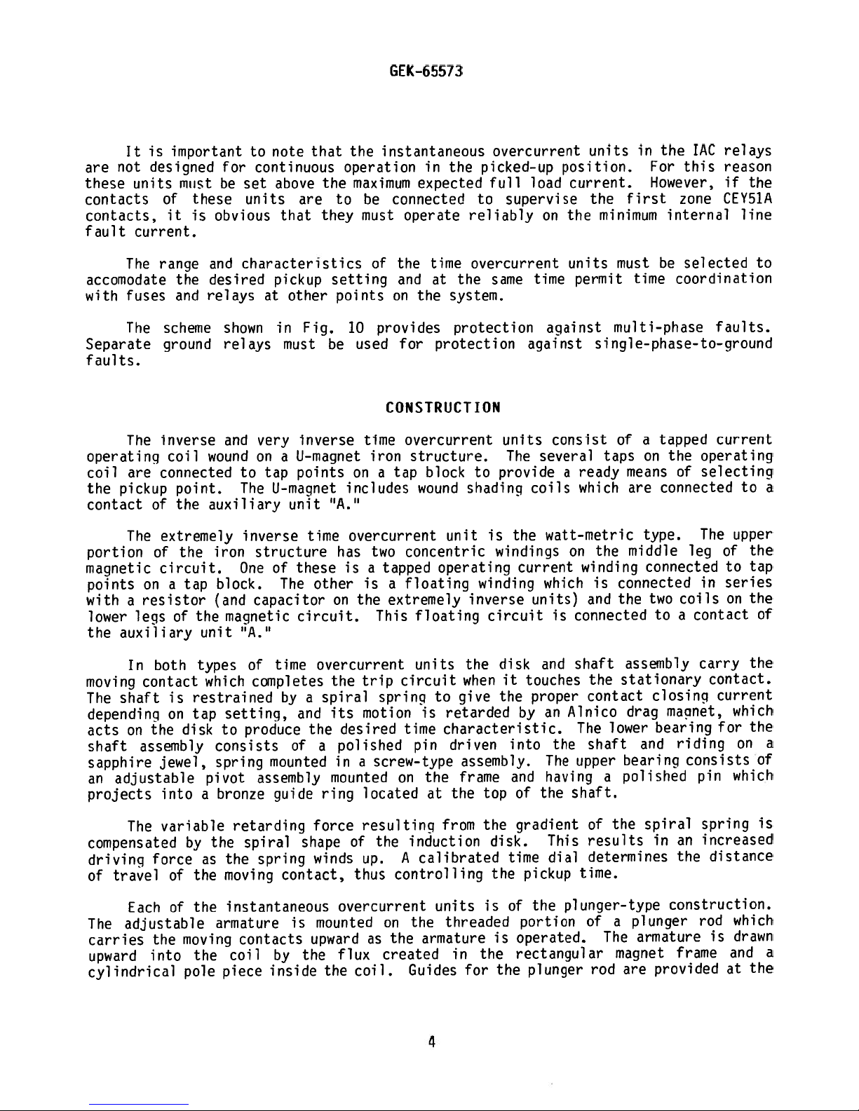
It
not
are
these
units
contacts
contacts,
fault
current.
The
accomodate
fuses
with
The
Separate
faults.
The
operating
are
coil
pickup
the
contact
The
portion
magnetic
points
with
lower
the
resistor
a
legs
auxiliary
is
important
designed
of
it
range
the
and
scheme
ground
inverse
coil
connected
point.
of
the
extremely
of
circuit.
on
a
of
must
these
is
the
tap
the
for
he
obvious
and
desired
relays
shown
relays
and
wound
auxiliary
iron
block.
(and
magnetic
unit
note
to
continuous
set
units
that
above
are
that
characteristics
pickup
at
other
Fig.
in
must
inverse
very
on
a
U—magnet
to
The
points
tap
U-magnet
unit
inverse
time
structure
of
One
these
The
capacitor
circuit.
hA.H
the
they
setting
be
“A.”
other
on
the
operation
maximum
to
he
must
of
points
10
provides
used
time
iron
on
a
includes
overcurrent
two
has
a
is
is
the
This
instantaneous
in
the
picked-up
expected
connected
operate
the
time
at
and
the
on
to
reliably
overcurrent
the
system.
protection
protection
for
CONSTRUCTION
overcurrent
structure.
tap
block
wound
to
shadinci
unit
concentric
tapped
a
extremely
operating
floating
winding
inverse
floating
overcurrent
load
full
supervise
time
same
against
units
The
provide
coils
is
the
windings
current
units)
circuit
units
position.
current.
on
the
units
permit
against
consist
several
a
ready
which
watt-metric
on
winding
which
and
connected
is
For
the
IAC
this
relays
reason
in
However,
first
the
minimum
must
time
multi—phase
zone
internal
he
coordination
CEY51A
selected
faults.
single-phase-to—ground
a
on
means
are
type.
middle
tapped
operating
the
of
selecting
connected
The
leg
current
of
of
taps
the
connected
coils
contact
a
in
is
connected
two
the
to
if
line
to
upper
to
series
on
the
to
a
the
tap
the
of
In
moving
The
contact
shaft
depending
the
on
acts
shaft
assembly
sapphire
an
adjustable
projects
The
compensated
driving
travel
of
Each
adjustable
The
carries
upward
into
cylindrical
both
is
on
jewel,
into
variable
force
of
of
the
types
which
restrained
tap
disk
consists
spring
pivot
bronze
a
the
by
as
the
the
armature
moving
the
pole
time
of
completes
by
setting,
produce
to
mounted
assembly
guide
retarding
spiral
spring
the
moving
contact,
instantaneous
contacts
coil
piece
by
inside
overcurrent
spiral
a
and
the
of
a
ring
force
shape
winds
is
mounted
upward
the
trip
the
motion
its
desired
polished
a
in
mounted
located
resulting
of
up.
thus
overcurrent
as
flux
coil.
the
units
circuit
spring
is
time
pin
screw-type
the
on
induction
the
A
calibrated
controlling
on
the
armature
the
created
Guides
the
when
give
to
retarded
characteristic.
driven
assembly.
frame
the
from
top
the
is
at
units
threaded
in
the
for
4
disk
it
the
by
into
and
of
gradient
disk.
time
the
of
portion
operated.
is
rectangular
the
and
touches
proper
an
the
The
having
the
This
dial
pickup
the
plunger
the
assembly
stationary
shaft
contact
Plnico
The
drag
lower
shaft
upper
bearing
polished
a
shaft.
the
of
results
determines
time.
plunger-type
of
a
The
magnet
rod
are
closing
macnet,
bearing
and
spiral
in
construction.
plunger
armature
provided
carry
riding
consists
pin
an
the
rod
frame
contact.
current
which
for
on
which
spring
increased
distance
which
drawn
is
and
at
the
the
a
of
is
a
the
Page 5

top
by
a
carrier
allow
inside
access
The
telephone-type
The
removed
top
are
inserted
cover
prevents
TIME
from
and
bottom.
completed
is
OVERCURRENT
hole
in
the
to
auxiliary
relay
components
the
through
in
place
attached
the
cover
the
the
relay
The
of
UNIT
pole
calibration
armature
unit
to
from
is
of
each
case.
electrical
removable
the
the
‘A”
shown
connection
being
piece,
is
relay
The
case
and
Lube.
to
adjust
a
telephone—type
in
Fig.
are
cradle
connections
connection
plugs
from
replaced
GEK—65573
at
the
Openings
pickup.
11.
mounted
is
locked
between
to
permit
the
front
until
RATINGS
bottom
relay.
on
plugs.
and
the
by
in
the
a
cradle
in
the
the
Separate
testing
includes
connection
the
sides
The
assembly
case
case
fit
of
of
the
construction
by
means
blocks
testing
the
relay
an
interlock
plug
has
the
calibration
which
of
and
in
been
molded
of
can
latches
cradle
plugs
its
inserted.
a
be
case.
arm
contact
tube
typical
easily
at
blocks
can
which
the
be
The
Ratings
Available
RANGE
AMPERES
0.5
of
the
RELAY
IAC6OT
IAC8OT
IAC9OT
taps
-
4.0
time
overcurrent
FREQUENCY
CYCLES
________
for
time
0.5,
60
60
overcurrent
0.6,
0.7,
unit
TABLE
MAIN
UNIT
0.5
2.0
0.5
1.5
units
TABLE
0.8,
are
I
PICKUP
(TIME)
-
4.0
-
16.0
-
4.0
-
12.0
II
TAPS
1.0,
given
in
RANGE,
are
shown
AVAILABLE
1.?,
1.5,
Table
I.
AMPERES
INSTANTANEOUS
J
on
2—50
Table
(AMPERES)
2.0,
2.5,
UNIT
LI
3.0,
4.0
1.5
—
12
2.0
-
16
1.5,
2.0,
2.0,
2.5,
2.5,
3.0,
3.0,
4.0,
4.0,
5.0,
6.0,
7.0,
8.0,
5.0,
6.0,
7.0,
8.0,
10.0,
10.0,
12.0,
12.0
16.0
5
Page 6
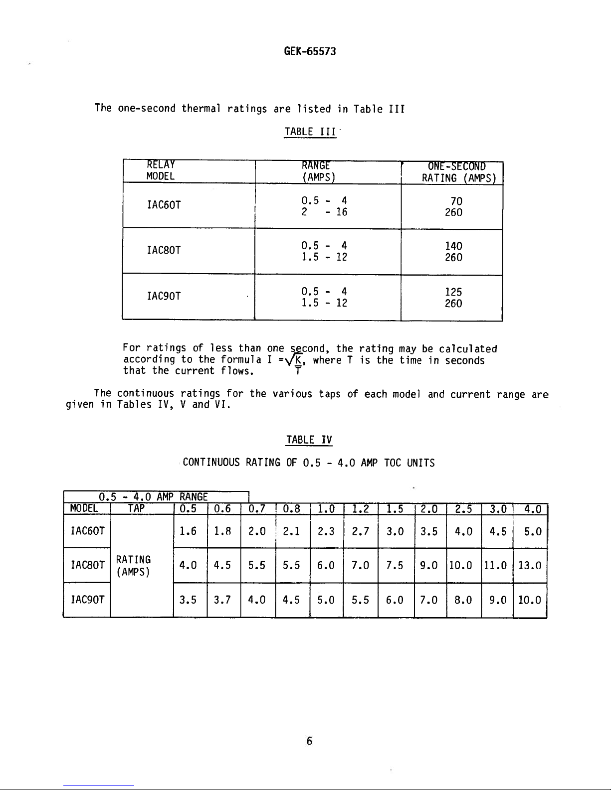
The
one—second
thermal
ratinqs
SEK-65573
are
listed
in
Table
III
given
The
in
RELAY
MODEL
IAC6OT
IAC8OT
IAC9OT
For
ratings
according
that
the
continuous
Tables
IV,
of
to
current
ratings
V
and
the
less
formula
flows.
VI.
for
than
the
TABLE
one
I
=./i,
various
RANGE
(AMPS)
0.5
2
0.5
1.5-12
0.5
1.5
second,
where
T
III
-
-
-
-
-
taps
16
12
the
ONE-SECOND
RATING
4
(AMPS)
70
260
4
140
260
4
125
260
T
of
rating
is
each
the
may
time
model
be
in
and
calculated
seconds
current
range
are
0.5
MODEL
IAC6OT
IAC8OT
IAC9OT
-
TAP
4.0
CONTINUOUS
AMP
RANGE
0.5
1.6
4.0
3.5
0.6
1.8
4.5
3.7
RATING
0.7
2.0
5.5
4.0
TABLE
OF
0.5
0.8
2.1
5.5
4.5
IV
1.0
2.3
6.0
5.0
-
4.0
AMP
TOC
UNITS
1.2
2.7
7.0
5.5
1.5
3.0
7.5
6.0
2.0
3.5
9.0
7.0
2.5
4.0
10.0
8.0
3.01
4.5
11.0
9.0
4.0
5.0
13.0
10.0
6
Page 7
GEK—65573
1.5
-1?.O
MODEL
IACBOT
IAC9OT
2
-
MODEL
IAC60(AMps)
RATING
TAP
RATING
(AMPS)
16.0
AMP
TAP
CONTINUOUS
AMU
RANGE
1.5
10.0
9.5
CONTINUOUS
RANGE
2.0
8.0
2.0
11.5
10.5
2.5
9.0
RATING
2.5
13.0
11.5
RATING
3.0
10.0
TABLE
OF
3.0
14.5
12.5
TABLE
OF
4.0
12.0
1.5-
2
17.0
14.0
-
16.0
5.0
14.0
V
4.0
VI
12.0
AMP
5.0
19.0
15.5
AMP
6.0
15.0
TOC
TOC
UNITS
6.0
21.0
17.0
UNITS
7.0
16.0
7.0
23.0
18.0
8.0
17.5
8.0
23.5
19.0
10.0
20.0
10.0
27.5
20.0
12.0
20.0
12.0
30.5
20.0
16.0
20.O
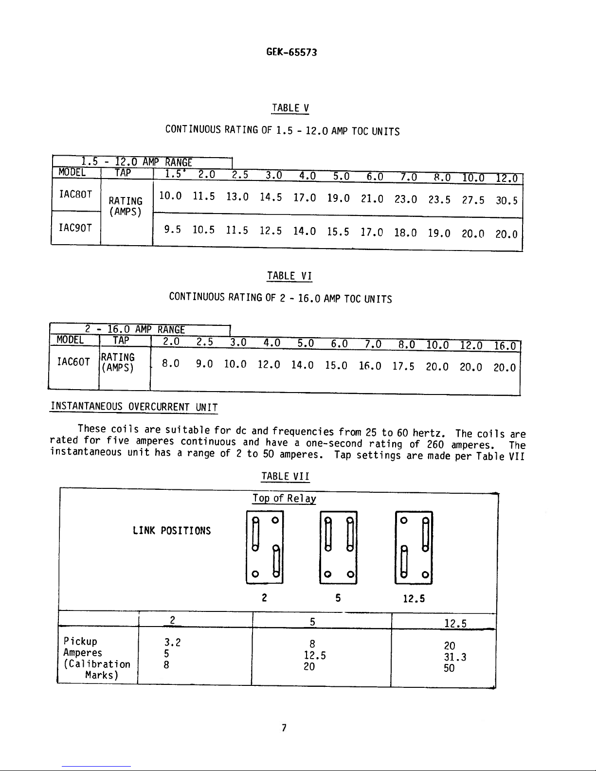
INSTANTANEOUS
These
rated
instantaneous
Pickup
Amperes
(Calibration
for
coils
five
Marks)
OVERCURRENT
are
suitable
amperes
unit
LINK
continuous
has
a
range
POSITIONS
3.?
5
8
UNIT
for
of
dc
and
2
and
to
Topof
frequencies
have
50
amperes.
TABLE
Relay
2
one-second
a
VII
12.5
20
from
25
to
rating
Tap
settings
8
60
hertz.
of
are
12.5
260
made
The
amperes.
per
12.5
20
31.3
50
coils
Table
j__________________________
are
The
VII
7
Page 8
GEK-65573
AUXILIARY
The
CONTACTS
The
carry
less.
breaker
30
The
auxiliary
amperes,
TIME
OVERCURRENT
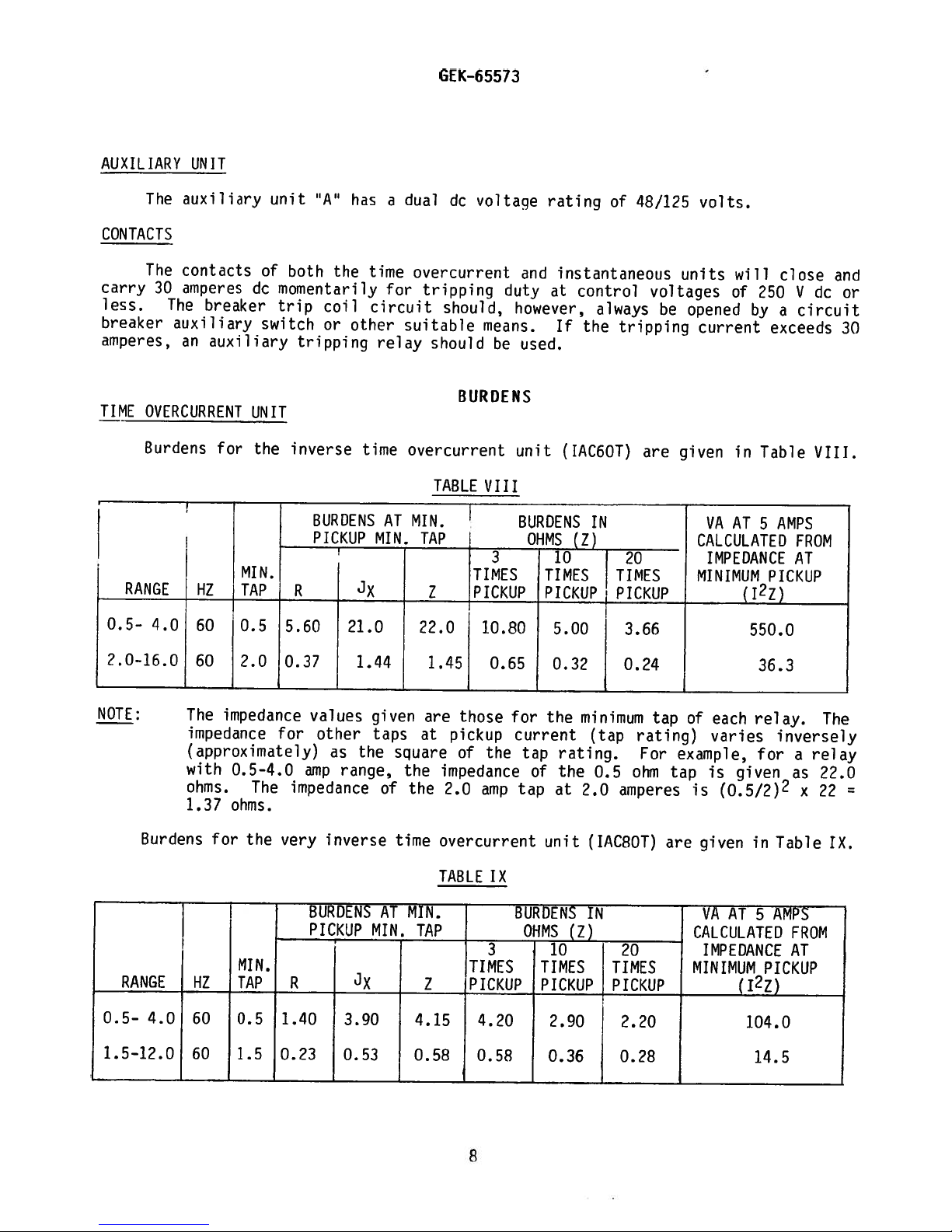
Burdens
RANGE
UNIT
auxiliary
contacts
amperes
breaker
an
auxiliary
for
HZ
unit
of
dc
switch
UNIT
the
MIN.
TAP
“A”
both
the
momentarily
trip
coil
or
other
tripping
inverse
BURDENS
PICKUP
R
has
time
circuit
relay
time
AT
MIN.
a
dual
overcurrent
for
tripping
suitable
overcurrent
MIN.
TAP
Z
dc
should,
should
B
TABLE
voltaqe
duty
means.
be
(JR
DENS
VIII
3
TIMES
PICKUP
rating
and
instantaneous
at
however,
If
used.
unit
(IAC6OT)
BURDENS
OHMS
(7)
10
TIMES
PICKUP
of
control
always
the
IN
48/125
voltages
be
tripping
are
20
TIMES
PICKUP
volts.
units
opened
will
of
250
by
current
given
VA
in
AT
Table
5
CALCULATED
IMPEDANCE
MINIMUM
(127)
close
V
circuit
a
exceeds
VIII.
AMPS
FROM
AT
PICKUP
dc
and
or
30
0.5-
.O-16.O
NOTE:
RANGE
0.5-
1.5—12.0
4.0
The
impedance
(approximately)
with
ohms.
1.37
Burdens
4.0
60
60
for
HZ
60
60
0.5
2.0
impedance
for
0.5-4.0
The
ohms.
very
the
MIN.
TAP
0.5
1.40
1.5
0.23
5.60
21.0
0.37
values
other
as
range,
amp
impedance
inverse
BURDENS
PICKUP_MIN.
R
3.90
0.53
1.44
given
taps
the
square
of
time
AT
22.0
1.45
are
at
the
the
MIN.
TAP
7
4.15
0.58
10.80
0.65
those
pickup
of
the
impedance
2.0
amp
overcurrent
TABLE
IX
3
TIMES
PICKUP
4.20
0.58
5.00
0.32
for
the
current
tap
rating.
of
the
tap
at
unit
BURDENS
OHMS
(7)
10
TIMES
PICKUP
2.90
0.36
3.66
0.24
minimum
(tap
0.5
2.0
amperes
(IAC8OT)
IN
20
TIMES
PICKUP
2.20
O.?8
tap
rating)
For
ohm
of
each
varies
example,
tap
is
given
(0.5/2)2
is
given
are
VA
AT5AMPS
CALCULATED
IMPEDANCE
MINIMUM
550.0
36.3
relay.
for
in
(12Z)
104.0
14.5
inversely
a
as
x
Table
FROM
AT
PICKUP
The
relay
22.0
22
IX.
=
8
Page 9
GEK—65573
NOTE:
Table
RANGE
0.5-
1.5-12.0
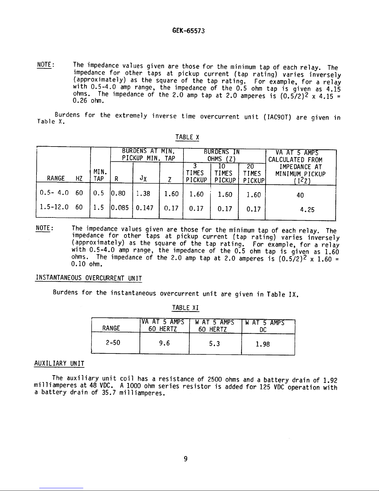
NOTE:
The
impedance
(approximately)
with
ohms.
0.26
Burdens
X.
4.0
The
impedance
(approximately)
with
ohms.
0.10
impedance
for
HZ
60
60
impedance
0.5-4.0
The
ohm.
the
M1N.
TAP
0.5
1.5
0.5-4.0
The
ohm.
values
for
other
amp
rnpedance
extremely
BURDENS
PICKUP
R
0.80
0.085
values
for
other
as
amp
impedance
as
ranqe,
1.38
0.147
range,
the
the
given
taps
of
inverse
AT
MIN.
given
taps
square
of
are
at
square
the
the
MIN.
TAP
Z
1.60
0.17
are
at
the
the
those
pickup
of
impedance
2.0
amp
time
TABLE
TIMES
PICKUP
1.60
0.17
those
pickup
of
the
impedance
2.0
amp
for
current
the
tap
tap
overcurrent
X
BURDENS
OHMS
3
for
current
tap
of
tap
the
rating.
of
the
at
10
TIMES
PICKUP
1.60
0.17
the
rating.
the
at
2.0
minimum
(tap
0.5
2.0
amperes
IN
(Z)
TIMES
PICKUP
minimum
(tap
0.5
amperes
unit
20
1.60
0.17
ohm
tap
rating)
For
example,
ohm
tap
is
(IAC9OT)
CALCULATED
tap
of
rating)
For
example,
tap
is
of
each
relay.
varies
is
given
(0.5/2)2
are
AT
VA
5
IMPEDANCE
MINIMUM
(12Z)
40
4.25
each
relay.
varies
for
is
given
(0.5/2)2
inversely
for
a
as
x
given
AMPS
FROM
AT
PICKUP
inversely
a
as
x
relay
4.15
relay
1.60
The
4.15
in
The
1.60
=
INSTANTANEOUS
Burdens
AUXILIARY
The
milliamperes
battery
a
for
UNIT
auxiliary
at
drain
OVERCURRENT
the
unit
VDC.
48
of
35.7
UNIT
instantaneous
coil
A
1000
milliamperes.
has
a
ohm
overcurrent
TABLE
resistance
series
XI
resistor
of
unit
2500
is
are
ohms
added
given
and
for
in
a
125
Table
battery
VDC
IX.
drain
operation
of
1.92
with
9
Page 10
TIME
OVERCURRENT
GEK-65573
CHARACTERISTICS
UNIT
Pickup
the
contacts
of
tap
The
close
just
travel
its
closed
the
The
The
to
zero,
The
IAC8OT
and
INSTANTANEOUS
of
from
value.
setting
contacts
when
maximum
percentage
time
is
approximately:
time-current
IAC9OT,
to
OVERCURRENT
the
time
the
of
when
the
distance
of
reset
respectively.
overcurrent
time-dial
0.5
the
time
the
current
dial
is
to
the
minimum
to
the
characteristics
UNIT
dial
set
close
IAC6OT
IAC8OT
IAC9OT
Number
IAC6OT
IAC8OT
IAC9OT
unit
position.
determines
reaches
at
zero.
the
closing
10
time-dial
are
is
the
When
contacts;
value
-
percent
90
-
80
percent
-
85
percent
-
7
seconds
-
60
seconds
-
57
seconds
shown
defined
The
pickup
the
length
predetermined
the
this
of
current
position,
in
Fig.
as
dial
gives
the
value
of
is
that
when
6,
current
is
time
value.
set
the
the
the
7
and
required
within
the
unit
The
at
10,
maximum
unit
current
8
for
three
contacts
the
time
will
the
to
percent
requires
disk
setting.
reset
is
reduced
IAC6OT,
close
to
are
must
is:
Pickup
markings
energized
These
cartons
examine
rough
and
promptly
Reasonable
the
parts
If
original
Foreign
cover
The
instantaneous
is
on
designed
it
handling
the
cartons
matter
is
removed,
set
the
position
relays,
for
notify
are
injured
relays
by
adjusting
calibration
between
when
to
protect
any
damage
is
evident,
the
care
are
in
collected
and
overcurrent
not
nearest
should
or
the
not
place
a
on
cause
the
vertical
tube.
85
and
95
RECEIVING,
included
them
against
sustained
file
damage
a
General
be
exercised
adjustments
to
be
installed
that
the
outside
trouble
unit
is
The
percent
HANDLING
as
in
transit.
Electric
is
free
of
in
the
continuously
position
instantaneous
of
part
of
damage.
claim
in
at
unpacking
disturbed.
immediately,
from
the
operation
10
of
its
pickup
AND
STORAGE
a
control
Immediately
If
injury
once
Apparatus
moisture,
case
may
of
adjustable
the
unit
with
the
they
find
the
armature
setting.
panel
or
the
Sales
relay
should
dust
relay.
over
will
reset
will
upon
receipt
damage
transportation
Office.
in
order
be
and
its
way
a
relative
be
resulting
that
stored
metallic
inside
25:1
to
the
shipped
of
a
company
none
in
when
range.
to
relay,
from
their
chips.
the
de—
in
of
the
Page 11
GEK—65573
Immediately
made
to
ensure
calibrations
readjustment
These
the
discretion
Since
installation
perlormed
VISUAL
on
INSPECTION
Check
relay
agree
Remove
molded
parts
MECHANICAL
Time
Overcurrent
upon
that
have
is
tests
most
not
necessary,
may
of
the
operating
tests,
these
the
with
the
or
relays.
nameplate
the
relay
other
INSPECTION
Unit
receipt
no
damage
been
be
performed
user.
the
following
stamping
requisition.
from
signs
of
disturbed.
refer
companies
its
case
of
physical
ACCEPTANCE
the
relay
has
been
If
to
the
section
as
part
of
use
section
to
ensure
and
check
damage,
TESTS
an
INSPECTION
sustained
the
on
the
different
includes
that
that
and
AND
in
shipment
examination
SERVICING.
installation
procedures
all
applicable
the
model
there
that
all
ACCEPTANCE
and
or
test
or
acceptance
for
tests
number
are
the
no
screws
and
broken
TEST
should
that
the
indicates
tests
acceptance
that
rating
or
are
tight.
relay
that
may
of
the
cracked
be
at
and
be
There
The
disk
Make
touching.
Instantaneous
The
the
movable
CAUTION:
EVERY
IMPORTANT
BRUSH
BRUSHES
DRAWOUT
BE
DO.
RELAY
Since
they
be
tested
effects
tested
makes
case.
of
without
connections
The
should
should
sure
Overcurrent
plunger
contact
CIRCUIT
ON
CURRENT
BENT
HIGH
THIS
TESTING
all
drawout
in
the
enclosure
removing
12XLA12A
be
return
the
assembly
arms
IN
ENOUGH
WILL
their
only
test
no
noticeable
by
itself
control
Unit
should
must
THE
DRAWOUT
CIRCUITS
TO
PREVENT
relays
cases
will
it
from
with
plug
spring
exhibit
be
securely
AND
OTHER
ENGAGE
THE
in
service
or
an
be
accurately
the
the
relay
may
also
friction
to
its
is
CASE
THE
CT
SECONDARY
equivalent
panel
and
be
when
rest
position.
not
deformed
no
tendency
fastened
HAS
AN
CIRCUITS
WITH
CONNECTING
CIRCUITS
operate
in
steel
duplicated
by
using
does
not
used.
Although
the
disk
is
nor
its
to
bind
to
the
AUXILIARY
SHORTING
PLUG
OR
FROM
their
cases,
case.
during
a
12XLA13A
disturb
this
rotated
convolutions
when
molded
BRUSH.
BARS
TEST
BEING
In
testing.
any
test
operated
contact
PLUG
it
this
test
shorting
slowly
IT
THAT
BEFORE
OPENED.
is
recommended
way,
A
plug.
plug
allows
clockwise.
tangled
by
hand
support.
IS
ESPECIALLY
THE
AUXILIARY
THE
any
magnetic
relay
This
bars
greater
may
in
or
and
MAIN
that
be
plug
the
11
Page 12
GEK-65573
testing
since
POWER
flexibility,
connections
REQUIREMENTS
All
alternating
sinusoidal
fundamental
affected
by
Therefore,
to
use
freedom
relay;
sine
a
from
however,
electromagnets
sinusoidal
TIME
OVERCURRENT
Rotate
close
at
the
Where
brush
its
in
or
support.
waveforms
frequency,
the
applied
in
wave
harmonics)
any
(such
waveforms.
UNIT
the
time
zero
time
the
contacts
out
by
it
requires
are
made
GENERAL
current
can
it
waveform.
order
of
current
relay
as
time
dial
dial
just
means
of
to
he
analyzed
follows
to
properly
cannot
using
slowly
setting.
its
CT
shortinq
both
the
operated
that
and/or
be
tuned
overcurrent
and
close
can
adjusting
relay
devices
as
a
alternating
test
voltage.
expressed
circuits,
relays)
check
be
screw.
jumpers
and
the
are
fundamental
alternating
The
as
a
would
by
means
adjusted
This
and
external
affected
frequency
current
purity
finite
R—L
of
by
screw
the
current
or
RC
be
essentially
a
running
exercise
by
devices
of
the
number
lamp
should
circuitry.
frequency.
plus
relays,
sine
for
networks,
that
the
stationary
be
of
greater
harmonics
(relays)
it
is
wave
any
or
affected
the
contacts
held
Since
of
will
essential
(i.e.,
particular
saturating
by
contact
securely
care,
non-
the
he
its
non-
just
in
With
between
gap
approximately
The
position
When
connection
screws
tap
plug.
The
adjusting
notches
brought
around
into
adjustment
intermediate
the
factory
within
minimum
Time
five
closing
Setting
The
close
its
the
contacts
the
1/32
minimum
of
the tap
changing
plug
into
pickup
ring.
agreement
has
between
to
percent
setting
contacts
stationary
current
to
the
of
See
the
been
close
value.
of
inch
screw
the
short
tap
the
Fig.
edge.
disturbed.
the
of
the
when
just
wipe.
current
marked
unit
with
various
its
the
time
the
closing
at
in
the
2.
By
turning
contacts
tap—plug
current
contact
which
the
current
for
for
The
the
dial
at
the
tap
setting
the
any
ring
the
tap
This
tap
settings
from
determines
reaches
No.0time
brush
contacts
of
at
the
block
transformer
desired
current
may
be
ring,
setting
adjustment
any
setting.
setting,
and
its
will
the
top
relay
secondary
current
tap
is
turned
the
operating
employed,
to
be
obtained.
time-dial
The
the
length
a
predetermined
just
by
also
unit
metal
the
of
while
and
adjusted
inserting
permits
position
resets
of
there
backing
close
circuit.
then
current
if
time
value.
relay.
in
replace
by
for
The
should
is
determined
the
case,
means
a
screwdriver
of
some
any
unit
at
a
at
90
the
The
be
strip
Next,
the
of
the
reason,
desired
is
minimum
percent
unit
requires
contacts
sufficient
to
ensure
by
remove
screw
connection
spring-
a
in
unit
may
setting
adjusted
current
of
the
the
the
the
be
this
at
the
to
are
1?
Page 13

just
closed
travel
maximum
The
the
tiiiie
along
while
moving
the
time
its
when
maximum
setting.
primary
dial.
supporting
it
the
dial
amount
adjustment
However,
shelf;
away
increases
is
to
for
further
moving
set
close
the
adjustment
the
on
the
time.
GEK-65573
zero.
the
contacts
time
of
magnet
When
operation
is
obtained
toward
the
and
dial
therefore
of
by
the
disk
is
the
moving
set
unit
shaft
on
this
the
10,
setting
is
made
permanent
decreases
the
by
disk
gives
means
magnet
the
must
the
of
time,
Pickup
connections
two
Time
test
The
INSTANTANEOUS
Test
Set
the
percent
Test
Set
the
connection
relay
relay
in
of
relay
will
UNIT
Fig.
tap
in
Fig.
operate
at
13,
value
to
the
the
and
0.5
the
current.
No.
13,
RELAY
IAC6OT
IAC8OT
IAC9OT
main
apply
the
time-dial
unit
5
time—dial
five
timing
position
should
position
times
should
TABLE
XII
close
tap
be
TIME
and
and
current
within
1.73
1.27
0.89
2.0
its
contacts
the
the
IN
SECONDS
-
-
0.95
(10.0
1.83
1.35
ampere
2.0
limits
tap.
within
ampere
amperes)
in
Using
tap.
Table
plus
to
Using
the
XII.
the
or
test
minus
the
relay.
Pickup
aligned
pickup
unit
operating
continuous
gradually
95
AUXILIARY
connected
percent
picks
The
at
percent
The
up
and
units
with
settinq
this
coil
decreased
UNIT
relays
for
of
and
Reset
are
the
on
setting,
motion,
of
pickup.
the
the
lower
wipes
the
are
normally
top
the
unit
at
until
normally
lower
voltage
in
mark
on
nameplate.
see
should
the
calibration
the
value
with
one
supplied
the
Fiq.
contacts
shipped
of
rating
from
calibration
It
should
14.
pick
up,
from
the
dc
across
continuous
With
closing
current
reset.
the
voltage
motion
13
the
factory
tube.
be
gradually
level.
The
factory
rating
terminals
sufficient
its
reset
9
of
the
with
This
increasing
normally
The
value
with
shown
and
armature.
the
bottom
corresponds
to
check
open
test
current
should
the
coil
on
the
10
and
of
to
the
pickup
test
current
contacts
should
be
between
circuit
nameplate.
check
that
the
the
of
armature
minimum
of
each
in
with
then
85
unit
Apply
unit
the
one
be
and
HAN
60
“A”
Page 14

GEK—65573
INSTALLATION
The
relay
lighted
is
Typical
The
shown
The
to
facilitate
relay
in
internal
external
INSTALLATION
The
following
Time
Overcurrent
1.
Set
approximatley
until
current
Check
2.
tap
the
user.
Instantaneous
should
Fig.
TESTS
tap
value
relay
Unit
should
15.
connection
connections
tests
Unit
screw
light
the
is
the
operating
may
must
installed
be
inspection
be
mounted
are
on
twice
defined
be
coordinate.
in
five
diagrams
are
to
be
desired
tap
series
as
pickup
time
times
in
and
on
a
shown
performed
value
with
at
a
clean,
testinq.
vertical
for
in
tap.
until
and
some
tap
The
Fig.
Using
the
should
multiple
rating
value
dry
surface.
the
10.
the
at
contacts
contacts
or
used
location,
relays
time
the
be
of
the
The
are
of
test
just
begins
within
the
maximum
is
left
free
outline
shown
installation:
circuit
close.
to
flicker.
two
tap
value.
fault
to
from
and
in
in
Reduce
percent
the
dust,
panel
Fig.
Fig.
This
of
This
current
discretion
and
drilling
4
13,
the
current
value
tap
multiple
for
well
and
apply
value.
which
of
5.
of
of
the
1.
2.
3.
4.
Auxiliary
The
the
on
the
of
voltage,
Ri
is
diagrams,
Set
Set
approximate
pickup
Gradually
pickup
Check
Unit
operating
relay
two
the
in
series
Fig.
the
the
that
nameplate.
voltage
dc
leads
4
desired
pickup
setting.
apply
(see
coil
to
with
and
position
Fig.
the
instantaneous
circuit
As
ratings.
terminal
the
6.
tap
by
current
14).
shipped
auxiliary
range.
turning
in
of
If
points
the
and
the
from
it
the
calibration
adjust
unit
auxiliary
the
is
desired
and
9
unit
bottom
the
resets
factory
should
9A
coil.
of
tube
armature
between
unit
the
to
operate
Refer
the
corresponding
as
85
“A”
has
unit
be
interchanged
to
knurled
required
and
a
dual
is
connected
the
the
95
unit
internal
armature
to
for
percent
rating
dc
at
so
the
the
of
for
the
that
connection
to
desired
correct
pickup.
as
the
higher
resistor
the
shown
lower
dc
14
Page 15

GEK—65573
In
view
it
is
important
interval
and
the
experience
is
sugqested
of
between
user’s
to
that
years.
These
original
serviced
TIME
OVERCURRENT
1.
tests
settings.
as
described
Perform
setting
2.
Perform
INSTANTANEOUS
Check
outlined
in
that
the
PERIODIC
the
vital
that
a
periodic
periodic
experience
select
the
are
the
points
intended
If
in
UNIT
pickup
in
service.
the
time
UNIT
the
instantaneous
INSTALLATION
role
of
checks
with
test
interval
listed
deviations
this
manual.
tests
tests
section.
CHECKS
protective
test
will
periodic
to
insure
as
described
as
AND
program
vary
testing.
best
below
that
are
encountered,
described
unit
ROUTINE
relays
depending
suited
he
checked
in
picks
be
the
the
in
up
MAINTENANCE
in
the
operation
followed.
upon
Until
to
relays
at
the
the
his
an
have
relay
INSTALLATION
the
INSTALLATION
at
the
It
is
environment,
user
has
individual
interval
not
must
section
section.
desired
of
power
a
recognized
type
accumulated
requirements,
of
from
deviated
be
retested
current
for
one
from
level,
system,
that
of
relay
enough
to
their
the
the
it
two
and
tap
as
AUXILIARY
Check
UNIT
that
INSTALLATION
CONTACT
consists
effect
left,
the
files,
SYSTEM
For
a
yet
tool
abrasive
TEST
CLEANING
cleaning
of
superfine
it
insures
Although
relay,
intervals
overall
based
section.
flexible
a
will
this
the
auxiliary
relay
file.
clean
the
paper
instruction
functional
on
the
contacts,
strip
The
off
cleaning
or
cloth
tests
customer’s
unit
of
any
operates
a
metal
polishing
corrosion
of
the
of
any
book
to
experience.
flexible
with
actual
kind
is
check
when
an
etched—roughened
action
thoroughly
points
to
clean
primarily
the
voltage
burnishing
is
so
and
of
relay
written
system
is
applied,
tool
delicate
rapidly.
contact.
contacts.
to
operation
should
surface,
that
Do
check
are
as
outlined
be
resembling
no
scratches
The
flexibility
not
and
recommended
used.
use
set
in
knives,
the
the
This
in
are
of
TAC
at
15
Page 16

sections
restoring
IF
any
are
of
them.
the
found
mechanical
to
be
out
or
of
GEK-65573
electrical
limits,
SERVICING
check
the
followino
points
described
points
should
in
be
the
previous
observed
in
MECHANICAL
Time
Overcurrent
1.
Contact
The
contacts
contact
travel.
which
When
the
time-dial
correctly
position
Loosen
shaft
The
leaf
inch
1/64
thin
screwdriver
Shaft
2.
End
play
upper
the
is
pivot.
die-cast
approximately
magnet.
inch
1/32
adjustment
ADJUSTMENTS
Unit
Adjustment
should
tip
should
The
contact
scale
the
dial
should
regulate
time
adjusted,
of
the
arm
the
until
screw
spring
the
which
contacts
on
deflection.
blade
End
Play
is
determined
Both
supporting
centered
upper
The
play.
end
is
completed.
have
be
wipe
position
is
regulate
attached
the
The
bearing
pivot
Be
aprroximately
deflected
is
of
moved
indicate
clamps
just
stop
deflection
between
by
the
and
frame.
in
should
sure
that
adjusted
the
to
the
the
to
the
the
make
arm
should
the
relative
pivot
The
the
then
both
about
zero.
dial
arm
air
by
brush
position
to
shaft,
to
for
can
leaf
are
lower
be
set
1/3?
1/32
turning
relative
If
read
which
the
zero
be
so
be
spring
positions
held
jewel
gaps
located
screws
inch
inch
the
where
it
does
zero.
is
shaft
time—dial
formed
increased,
and
in
position
must
of
the
so
are
wipe.
when
to
and
the
of
that
screws
the
the
contacts
not
This
located
turn
setting.
that
if
stop
the
be
driving
the
securely
That
the
in
brush
and
is
done
below
the
there
necessary,
arm.
lower
means
by
located
magnet
shaft
is,
the
disk
the
stop.
just
the
by
the
arm
relative
is
jewel
of
so
has
tightened
stationary
completes
contact
brush
close,
brushes
changing
time
dial.
to
approximately
by
forcing
bearing
set
screws
that
the
the
and
inch
1/64
after
its
the
are
the
the
a
and
in
disk
drag
to
the
Friction
3.
to
gaps
any
slot,
tube.
to
bind
the
disk
can
tendency
contact
and
If
a
tendency
obstructions
drag
magnet
Instantaneous
1.
Friction
If
there
that
guide
the
plate
Unit
is
moving
calibrating
travel.
interfere
to
guide
that
or
no
excessive
with
bind
pin
foreign
Dirt
or
is
friction
or
the
motion
excessive
centered
matter
16
metallic
is
is
evident,
particles
of
the
disk.
friction
and moves
present
in
is
present,
freely
between
first
the
in
the
check
wattmetric
check
U-shaped
the
armature
to
for
or
see
and
Page 17

Moving
2.
The
flexible
assembly
should
straight
degree
and
the
ELECTRICAL
Time
Overcurrent
1.
Pickup
The
current
tap
screw
firmly
the
relay
connection
Contact
Leads
moving
centrally
be
reshaped
back
to
the
bend
in
the
bare
lead
ADJUSTMENTS
Unit
Adjustments
at
which
in
the
tap
into
the
tap
is
in
plugs
have
contact
located.
as
slot
lead
should
the
block
position
service
follows:
at
project
contacts
at
been
leads
If
these
in
the
a
point
the
marked
the
tap
withdrawn.
GEK-65573
should
moving
the
insulated
compound
just
either
operate
top
of
the
with
screw
be
contact
mounting
beyond
up
or
is
unit.
the
desired
must
formed
portion
the
down
normally
The
not
to
leads
plate.
end
to
the
controlled
tap
pickup
be
keep
have
of
the
There
of
the
terminal
screw
current.
removed
the
moving
been
deformed,
lead
should
insulating
by
should
until
should
screw.
means
be
Note
the
contact
extend
be
a
sleeve,
of
screwed
that
relay
they
90—
the
if
2.
The
pickup
adjusting
around
brought
adjustment
setting
close
percent
In
making
Note
that
Pickup
Normally
unit.
is
found
CHECKS,
supporting
moving
towards
on
the
moved
of
the
the
between
its
of
Time
If
it
it
the
disk
away
disk
of
ring.
edge.
into
has
contacts
the
pickup
the
Adjustments
pickup
the
to
be
can
shelf.
away
shaft,
for
from
at
the
The
By
agrenent
been
the
tap
checks,
“A”
unit
time
pickup
outside
be
restored
from
all
the
the
smallest
unit
ring
turning
disturbed.
various
from
plug
contacts
is
time
Moving
the
be
sure
positions
shaft,
for
may
with
tap
any
time—dial
setting.
use
controlled
for
the
by
the
shaft
that
its
radius
any
be
turned
the
the
This
settings.
the
connections
must
a
particular
limits
changing
magnet
increases
in
of
the
outer
current
ring,
tap
by
mentioned
its
disk
edge
of
tap
by
inserting
the
setting
adjustment
The
position
be
closed
means
the
towards
the
final
and
must
the
disk.
is
adjusted
operating
employed,
also
unit
at
of
Fig.
during
of
the
time—dial
in
position
the
time.
position
shaft
be
at
by
a
screwdriver
current
if
for
makes
is
adjusted
a
minimum
13.
tests.
time
dial
setting
ACCEPTANCE
of
the
shaft
If
is
decreases
the
drag
clears
assembly.
least
1/8
means
of
some
possible
at
current
at
and
TESTS
drag
magnet
the
If
inch
of
a
in
the
the
unit
reason
any
the
factory
within
the
top
pickup
and
multiple
PERIODIC
magnet
the
time
is
counterweight
the
magnet
from
the
spring—
notches
may
this
desired
five
of
the
its
on
while
moved
is
edge
be
to
Instantaneous
Refer
to
Unit
the
INSTA[LATION
section
for
current
17
pickup
adjustments.
Page 18

GEK-65573
to
enable
Electric
model
it
When
number
is
recommended
the
prompt
ordering
Company,
of
specify
the
that
replacement
renewal
quantity
relay
sufficient
parts,
for
of
which
RENEWAL
quantities
any
that
address
required,
the
part
PARTS
are
the
name
is
of
renewal
worn,
nearest
of
the
required.
broken
Sales
part
parts
or
Office
wanted,
carried
be
damacjed.
of
and
the
give
in
stock
General
complete
18
Page 19
GEK—65573
LIST
OF
FIGURES
PAGE
Fiq.
Fig.
Fig.
Fju.
Fig.
FiQ.
Fig.
Fig.
Fig.
Fig.
Fig.
Fig.
Fig.
1
JAC6OT
IAC6OT
2
3
IAC9OT
4
JAC6OT
5
IAC9OT
6
Inverse
7
Very
Extremely
8
Instantaneous
9
10
External
11
Auxiliary
12
Cross
Test
13
Relay,
Relay,
Relay,
and
TAC80T
Internal
60
Hertz
Inverse
Inverse
Connections
Unit
Section
Connections
Front
Rear
Rear
Connections
Time
60
Hertz
Unit
of
Drawout
-
View
View
View
Internal
Curves
Hertz
60
Time
Time
Connections
Time
Curves
Time
Curves
Case
Overcurrent
Curves
Connections
Unit
19
20
21
22
23
24
25
26
27
28
29
30
31
Fig.
14
Test
Connections
Fig.
15
Outline
and
Panel
-
Instantaneous
Drilling
19
Unit
32
33
Page 20

GEK—65573
Fig.
1
(Later)
IAC6OT
Relay,
Removed
20
from
Case,
Front
View
Page 21

GEK—65573
Fig.?
(Later)
IAC6OT
Relay,
Removedfrom
21
Case,
Rear
View
Page 22

GEK—65573
Fiq.
3
(Later)
Type
IAC9OT
Relay,
Removed
22
from
Case,
Rear
View
Page 23

GEK-65573
II
13
i*
15
TOC
WOUND
SHADING
17
Is
lOC.
02
COILS
A
CONNECTIONS
SHOWN
LOWER
HIGHER
AIER(HANGE
LEADS
2
=
SHORT
*
Fig.
4
FINGER
(0275A4595—O)
Internal
Connections
for
B
Relay—Types
ID
IAC6OT
and
IAC8OT
FOR
RE
RATING.
RATING
FOR
THESE
23
Page 24

GEK—65573
Tio
clio
ç
TOC TOC
*
02
5
17
c
TOC
SHADING
R
bC’
WOUND
COILS
A
C4
CONNECTION
SHOWN
LOWER
HIGHER
INTERCHANGE
A
RATING.
THESE
ARE FOR
RATING
LEADS
S
FOP
=SHORT
FINGER
Fig.
5
(0275A4596—O)
Internal
8
Connections
24
for
Relay-Type
I0
IAC9OT
Page 25

a,
L7
C-fl
c-i)
SECONDS
IN
-
‘a
-
rn
0,
1
-,
‘a,
700
40
0))
1.a
‘cc
000
100
I00
00O
0)00
4000
.
V
—
-
—
0000
—
0000
—
0000
-
-
00:7
,c,00
—
88888k
8
-
0
-
0
-
0
—
--
0
o
00
o
-:
-
-“
0
‘
0
0
—
.i’
0
0
Ni
0
-,
0
—
-i
0
0
0
•
000
O0Ni
00..00
0
0
0
•
—0
Ni
a,
Lfl
=
0
0
0—
>0
C-4
8
3
H
-+
-
——--
:
I-
-
31(IL
NI
———--
———-—-
---
-----
————-
——--——-
—-
—-
--
——.——--
h———
uNO3
L772;
--
---
--
:1:
-
,‘;I___
Settings
Dial
---I
———--
—--
——--
-
--
:-
—-
——--
———-
-——--
-——--
:
—
--
--
:::::
-—-
C
I
—I
-U
r
(I)
1
0
—
—
Time
—
-
-
88•-
-
3
-
8
--
-
-
-
-
-
-
8
II
m
I
-<
-
:
-U
LI)
-1
z
-I
m
6)
——
—-
loot—-
—
1I
m
0,
Co
Co
0,
(J
=
-5
0,
C
-
-
C-,
-S
T
r\)
,
-S
CD
-S
C-)
Di
Di
Li,
C-,
-
C-)
Li,
-5
0
CD
-
Di
CD
C-)
C
a,
Page 26

2
I
LtJ
I
I
I
Oto
:0—
toO
.1.00
0
C
0
—
to
tO
z
to
to
o
(0
.1.000
0
C-
to
—
0=
to
0
-
o
(0
0
c
-
0
0
—
-
cc.”-,
0
—
-
C
-.
NI
2
I
o
—
L.
=
—
t_-t
(C
to
c-to—
-
C
Lt
—
‘—C
C
-,
-o
to
=
I—
—
to
cc
>-
—O
II!!!!
I
I
1
III
I
I
£GNO3c
NI
U
H
H
EEEE
EEE
HEEE
EE’
,
EE
rE’E—’
—
—
-
::
-
-
:::
—
—
—
-
::
-
- -
::::z
---
--
--———
-————
--
--————
---———
---
.-—
sujsoIQeuIIj
-————
--———
-
-
--——
.
---—
-.--
---
-——
--
-
--——
---—
—
--
--——
-
--
——
---—
—
--
----——
-
.—-——
--
---——
--
--
-
---——
--——
-
-
-
-
——
--
——
--
I
liME
---—
---—
--
-——
IN
*a
H
‘
E
—
:
EEEE:
- -
—
—
—
—
S
-
-
----
——NI
—
—
_“•
--
ci
-
-
-
-
-
—
a)
----—a.
c
-
-
-
-
-
---—
---—
---—.——
——
—
1
I-.
C,
z
—
C
03
S.
Q-)
>
I
I
I
I
Page 27

.0
.0
.7
.4
100
410
040
I04
00
IC
70
10-
I.-
44-
00-
,-
RAT
I
TIME
0.5-9.0
1.5—12.0
2-5
————-
——-——-
————-
—
I
0
BOO
UNIT
INST.
0.
2—16
I
0-661
20-60
IJNIT
-Ll.
—--
—--
411
7
0
--
--
--
--
--
GEK-65573
I
III
————-
————-
————-
———--
———--
00
00
40
00
10101010.—
EXTE
t
CEID
0.5,0.6,0.7,O.8,,.U.l.2,l.5,2.0,2.S,3.0,4.0
.5,2.0,2.5,3.0,4.0,5.
2.0,2.5,3.0,
RM’IC-E
TIME
LI.
0,5.0,6.0,7.0,
UNIT
--
(80C
TAPS
0,6.0,7.
--
--
--
--
H
I
H
I
I
I
I
II
I
SERIES)
ADJ
ml
US
INST
UNIT
CONT
I
0,6.0,
10,
8.0.
——
———
——
——
——
2.
0.0,
5
12,
—-C---
—
--
—
-
-
.
----
—--
—--
—--
—-—
-——-—
---
--
——
——
——
NIJOUSLY
ADJUSTABLE
—
—
-
-
F
NT
S
-
-
-
-
-
III
HI
100
—--
—--
—--
---
---
I.
II
II
JO
1)
I’-
z
0
C.)
L.2
—
!th\r::
\__
--
—----
--
—---
EEE
--
—---
EZEEEE:
.4
0”
2
Lfl
0
2
.7.
a
-I
I
-7
Fig.
8
(0888B0274-.5)
0
7
4
I
1
I
I
III
III
MULTIPLES
60
Hertz
20
20
Time-Current
JO
JO
OF
40
40
IO7II0II
IO7IId4,
00
00
RELAY
Characteristics
27
TAP
g
s
SETTING
for
Relay-Type
IAC9OT
I
!1H(
Page 28
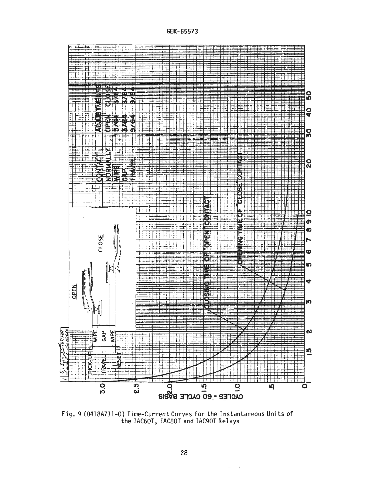
m
JUt
BIN
ii
:1
50
E]
40
30
20
f!
4HrItt
[1
4:
.JUL.
P
iiI-fltE
1
Tt4I1;
fl.i44:tl
tfffft
-1
-H
utr.
4t
CLOSE
-
trr!J
j$
OPEN
II
tL
f
—---________
-
GAP
-
I
I
i•
it
I
1
I
3.0
2.5
W
rr
-
-
-
I;!
1i
•
TjTBI1T
[UIt4I
--j
\-1
>
oI.5
1
CD
78910
•1
..‘
j
r
56
4
3
I
II
-
L
—
1
I.C
i
I
(.1)
2
15
CI
-
.
-..
I.-
-
ID
-
ID
c
Page 29

j1
-Il--I
GEK-65573
——II
I.,
‘
[]
I1
Fig.
10
(014507101-0)
Elementary
Diagram
29
for
Two
Zone
Distance
Protection
Page 30

GEK—65573
OPERATING
RESIDUAL
ARM____
SCREW
LOCKNUT__/
--
CONTACTS
HEEL
END
COIL
Fig.
11
(O3O546)
the
Typical
IAC6OT,
Telephone—Relay
TAC8OT
and
30
IAC9OT
Unit
Relays
Used
in
Page 31

BLOCK
CONNECTING
m
C,,
—4
PLUG
ON
BRUSH
BAR
BLOCK\\
CONNECTING
MAIN
THE
TERMINAL
SHORTING
BRUSH
BRUSH
MAIN
PLUG
CONNECTING
AUXILIARY
BRUSH
ENGAGING
AUXILIARY
1/4
NOTE:AFTER
ENGAGING
BEFORE
BLOCK
INCH
TERMINAL
THE
TRAVELS
U-’
C)
C)
C-,
o
:-
z
0’
J
-..
(0
-‘
0
(F,
(0
0
Page 32

GEK-65573
APA[LF
OP
LOAP
PFSSTANCE
BOX
115
VOLTS
‘—0--i
125/250V.
SW!
60
TCH
CYCLES
(-I-)
(—)
D.C.
L7.\
8
TOC
DOTTED
Fig.
CONNECTIONS
13
(0165A6029-O)
of
—
—
APE
the
j
FOR
PHASE
Test
Connections
IAC6OT,
2
IC8OT
UN!T
and
32
TEST.
for
the
LLC9OT
Time
Rel
Overcurrent
ays
Unit
Page 33

GEK-65573
VARIABLE
OR
LOAD
—0
—-
11
131
14’
L
--J
RESISTANCE
BOX
15
16
(%21
_I
L
VARIABLE
RESI
[GAB
OR
0
TEST
19
20
0
STANCE
BOX
PLUG
(UPEP)
115
60
VOLTS
CT’CLE
FIG.
14
Fig.
14
(0165A6028—O)
Test
of
Connections
the
IAC6OT,
for
IAC8OT
33
the
Instantaneous
and
IAC9OT
Relays
Overcurrent
Units
Page 34

GEK—65573
PANEL
SEMI-FLUSH
MTG
LOCATION
SURFACE
MTG
NUMBERING
(BACK
—I9
171513
00000
00000
20
IS
7
00000
00000
5
6
VIEW)
IG
14
531
4
OF
STUDS
II
12
2
DRILL
GI-4OLES
(MM)
PANEL
MOUNTING
DRILLING
(FRONT
Fig.
FOR
15
(6209276-3)
SEMI-FLUSH
VIEW)
Outline
IAC6OT,
VIEW
SHOWING
ASMBLY
HARDWARE
SURFACE
ON
STEEL
and
Panel
IAC8OT
and
OF
FOR
MTG
PANELS
Drilling
IAC9OT
(I2ML4j
RACE
Relays
MM)
.SOOTYPICL
PANEL
MOUNT4NG(FRONT
Dimensions
‘
DRILLING
for
(44MM)
1.75
FOR
the
(p9MM)
DRILL
)H0LE5
0TH
S4JR
ViEW)
)MM)
7
5
(502MM)
-
19.75
ENDS
)
34
Page 35

Page 36

GE
Power
Management
Anderson
215
Markham,
Canada
Tel: (905)
Fax:
www.ge.comlindsyslpm
L6E
(905)
Avenue
Ontario
1B3
294-6222
201-2098
 Loading...