

Page 1
TM
Homespring
by GE
Water Purifier System
Operations Manual
1
Page 2

A. INTRODUCTION .................................................................. 3
B. SAFETY WARNINGS ........................................................... 4
C. INSTALLATION INSTRUCTIONS - VERTICAL ................. 6
D. COMMISSIONING - VERTICAL .................................... 16
E. INSTALLATION INSTRUCTIONS - HORIZONTAL ... 21
F. COMMISSIONING - HORIZONTAL .............................. 35
G. ANNUAL MAINTENANCE ............................................. 40
H. WINTERIZATION PROCEDURE ................................... 42
I. TROUBLESHOOTING ........................................................ 45
J. SPECIFICATIONS ............................................................... 47
K. FREQUENTLY ASKED QUESTIONS (FAQ)................. 48
L. REPLACEMENT PART LIST AND PROCEDURES .... 50
M. HOMESPRING WATER PURIFIER SYSTEM LIMITED
WARRANTY ............................................................................. 56
2
Page 3

A. INTRODUCTION
Thank You!
By purchasing the Homespring Water Purier System, you
have taken the rst step in providing safer, great tasting water
for your entire home.
The Homespring Water Purier System (the System) is an
advanced Point of Entry (POE) water ltration system that
uses ultralter membrane technology to provide a physical
barrier to bacteria, parasites, viruses, and particles. The
System requires minimal maintenance and will provide you
with years of cleaner, safer, better tasting water. Simply follow
the information found in this manual and schedule an annual
maintenance visit with your Homespring Dealer.
The System must be installed in strict compliance with
provincial or state laws and local laws and regulations. The
System should only be used to lter water less than 100
(38oC) and must be protected from freezing.
Dealer and System Information
Dealer’s Name
o
F
Legal Disclaimer
This manual outlines some of the basic principles of household
water collection, treatment, and discharge and some of the
features of the Homespring Water Purier System. It is not
intended to be a denitive dissertation on the principles set
out above, nor is it intended to be relied upon by anyone but
Homespring Customer Care (“Consultants”) and Qualied
Technicians. Any other reliance is expressly excluded.
The Homespring Water Purier System must be installed by a
Homespring Authorized Technician and properly maintained
in accordance with the Operations and the Owner’s Manual.
Failure to properly maintain the System will compromise
performance and/or result in the failure to control water
quality.
Servicing Information
All service and maintenance must be performed by a
Homespring Authorized Technician. Should service be required
during or after the warranty period, or should you have any
questions regarding how to use your Homespring Water
Purier System, please contact your Homespring Dealer.
IMPORTANT! - Read First
Dealer’s Phone Number
Model Number
Qualied Technician
Customer Care Number 1-800-279-9404
Emergency Customer Service Number
Membrane Module Serial Number
Backpulse Tank Serial Number
Backpulse Tank Pressure Setpoint
Installation Date
Supplier Contact Information
Pentair Residential Filtration LLC
5730 North Glen Park Road
Milwaukee, WI, 53209
Tele: 262.238.4400
Fax: 262.238.4404
www.homespring.com
• Read this manual carefully prior to using the System.
• Permanently locate this manual near the System for
future references.
• Periodic checks of the System are required to ensure
safe and ecient operation.
• Annual maintenance by a Homespring Authorized
Technician is required to validate the limited warranty.
• Cost of all maintenance visits is the Owner’s
responsibility.
• Most tools referenced in this manual are available
through your Homespring Dealer.
• During servicing of the System, the water supply in your
home will be temporarily interrupted.
3
Page 4
B. SAFETY WARNINGS
It is important to read and understand the following safety
warnings to ensure reliable service from your System.
WARNING:
All System Parts and Components must be installed in
accordance with all local building and plumbing codes.
Operational
WARNING: Biological
The System is not intended for the treatment of water
from an obvious contamination source (such as sewage or wastewater).
Biolm and pathogens already present in home piping
lines downstream of the System could migrate into
ltered water unless the piping has been properly
sanitized. All household piping and distribution lines
should be sanitized prior to consuming the ltered
water using proper sanitization procedures (see your
local Health authority). The System owner should verify
the water outlet quality at the outlet sources by having
it tested by an approved or qualied water testing
laboratory prior to consumption.
The System must be commissioned and maintained in
accordance with the Owner’s Manual by an Authorized
Service Person. Failure to properly maintain the System
will compromise performance, shorten the life of the
System and may lead to delivery of contaminated
water. Consuming contaminated water could result in
serious injury or possibly death.
The System must be installed on a cold-water supply
line only. Failure to do so may cause System damage,
leading to personal injury and/or physical damage.
The System has been designed and tested to oer
reliable service, provided it is installed, commissioned,
operated, maintained and tested in strict accordance
to the safety instructions contained in this manual.
Failure to properly maintain the System will compromise
performance and/or result in a failure to control water
quality which may lead to delivery of contaminated
water. Consuming contaminated water could result in
serious injury or possibly death.
To avoid System damage, ensure that a Stainless Steel
Prelter or Carbon Prelter is in place during operation
of the System. Failure to do so will void all warranties.
In the absence of either lter, abrasive damage to
the System may occur. A damaged System may
permit contaminated water to enter the household
distribution system causing illness or death. Irreversible
and premature fouling of the System may also occur
resulting in System replacement at the owner’s expense.
Cap when System is under pressure.
Do not attempt to remove System
WARNING: Winterization
The System will be damaged if frozen. The System must
be winterized according to the Winterization Procedure
described in this manual.
The System must be winterized prior to temperatures
falling below 32°F(0°C). Failure to do so may cause the
System to dry, freeze, become damaged, and will void
all warranties. Operating a damaged System may lead
to personal injury, and/or physical damage.
The System must be kept wet at all times after
installation. Do not let the System dry for longer than
12 hours. Failure to do so may damage the System
causing personal injury, physical damage, illness and/
or death and will void all warranties.
Premature fouling of the system is not covered by
the warranty. After the installation of the System if
any noticeable pressure drop occurs, call your local
Homespring Authorized Service Person.
Except in emergencies, do not open the Bypass Valve
(if applicable); Bypassing the System may contaminate
water supply and water supply system.
Always wash hands thoroughly with soap and water
after performing any servicing procedures on the System.
Do not plug the Controller transformer in the electrical
receptacle if there is water on the electrical wiring or
on the power supply. Dry o all components rst. ONLY
OEM parts supplied by the manufacturer are to be
used when installing or servicing the ltration system
(System). Failure to follow this instruction may result in
System damage, serious personal injury, death and/or
property damage. Use of non-OEM parts will void the
manufacturer’s warranty.
4
Page 5
WARNING: Emergency Bypass
If System is equipped with a Bypass Valve, do not
open Bypass Valve except in emergencies. Opening
the Bypass Valve will permit potentially microbially
contaminated water to enter the household water
distribution system. Drinking contaminated water may
cause serious illness and/or death. Do not drink the
water if the System has been operated in bypass mode.
If the System has been operated in bypass mode and
if the water is being drawn from a well or surface
water source, the System and the household water
distribution system should be disinfected again once
returned to ltration mode.
If the System is in bypass mode, the Controller must be
unplugged. Failure to do so may cause System to dry
and become damaged, leading to personal injury, and/
or physical damage and will void all warranties.
A bypass is not required for proper operation of the
System. However, some local plumbing codes may
require a bypass. If a bypass is to be installed, the
procedure described below is to be followed in order
to provide water in an emergency or during System
malfunction.
Bypass Procedure
1. Close Inlet and Outlet Valves. (If ball valves are
installed, turn the handles perpendicular to the
water pipe.)
2. Open Bypass Valve (If ball valve is installed, turn
the handle in-line with the water pipe).
3. Unplug Controller.
To return to ltered water service:
1. Close Bypass Valve. (If ball valve is installed, turn
the handle perpendicular to the water pipe.)
2. Open Inlet and Outlet Valves. (If ball valves are
installed, turn the handles in-line with the water
pipe.)
3. Plug in the Controller.
4. Follow the System Membrane Cleaning section
under G. ANNUAL MAINTENANCE in this manual
to re-commission the System.
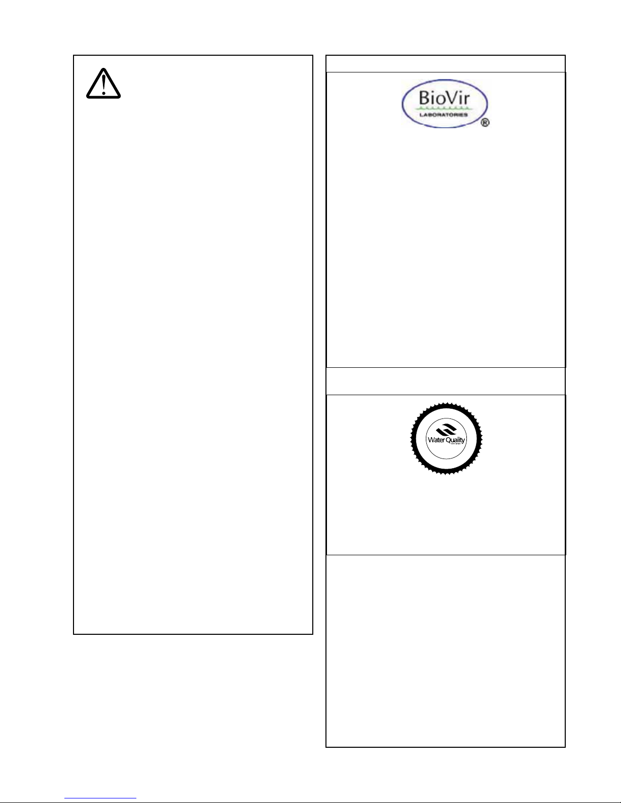
BioVir Laboratories
NELAP* and California Department of Health accredited
laboratory
*National Environmental Laboratory Accreditation
Program (NELAP) Accredited #05234CA
The Homespring UF200 Series Water Puriers have
been tested by BioVir Laboratories Inc. and found
to meet all the requirements of the USEPA’s Guide
Standard and Protocol for Testing Microbiological Water
Puriers (OPP Task Force Report, 1987) as interpreted by
the BioVir Laboratories specically for the Homespring
UF200 Series Products.
The test results were:
**Bacteria Reduction: >99.99999%
***Virus Reduction: >99.999%
*National Environmental Laboratory Accrediation
Committee (NELAC) Accredited #05234CA
**Tested with E.coli bacteria
***Tested with MS2 Coliphage
Water Quality Association
D
C
N
E
A
R
T
D
I
E
T
S
E
T
U
N
D
E
R
I
N
The Homespring UF200 Series Water Puriers have
been Tested and Certied by the Water Quality
Association (WQA) to the USEPA’s Guide Standard and
Protocol for Testing Microbiological Water Puriers (OPP
Task Force Report, 1987) as interpreted by the WQA and
to NSF/ANSI 42 and 53.
F
I
E
D
S
D
R
A
D
N
D
A
T
U
S
S
T
Y
R
5
Page 6
C. INSTALLATION INSTRUCTIONS -
Water Inlet to the House Filtered Water to
VERTICAL
All sales, commissioning and maintenance personnel are
required to participate in a Homespring Certied Technician
training program to ensure that they have been trained to
maintain and diagnose the system. Since the primary usage
of the system is to remove bacteria, certain parasites, and
certain viruses from drinking water sources, this certication
program is important and mandatory for both safety and
liability reasons.
All eorts must be made to ensure that installations are
performed in a careful, sanitary manner for the safety of the
homeowner, home occupants, and technicians.
The following section outlines the installation procedures,
the tools required in the installation, and the commissioning
procedures.
NOTE: The images in this manual may appear slightly dierent
than the actual system or parts.
WARNING: To reduce the risk of
severe injury, illness, death and/or property damage,
read and follow all instructions. Use only factory
supplied parts, where required.
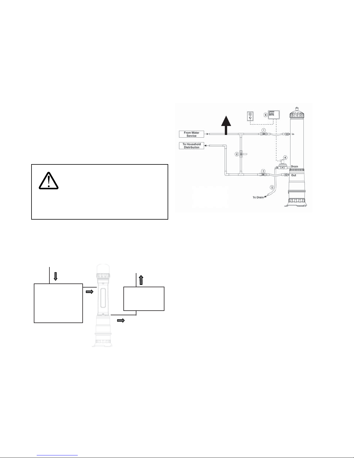
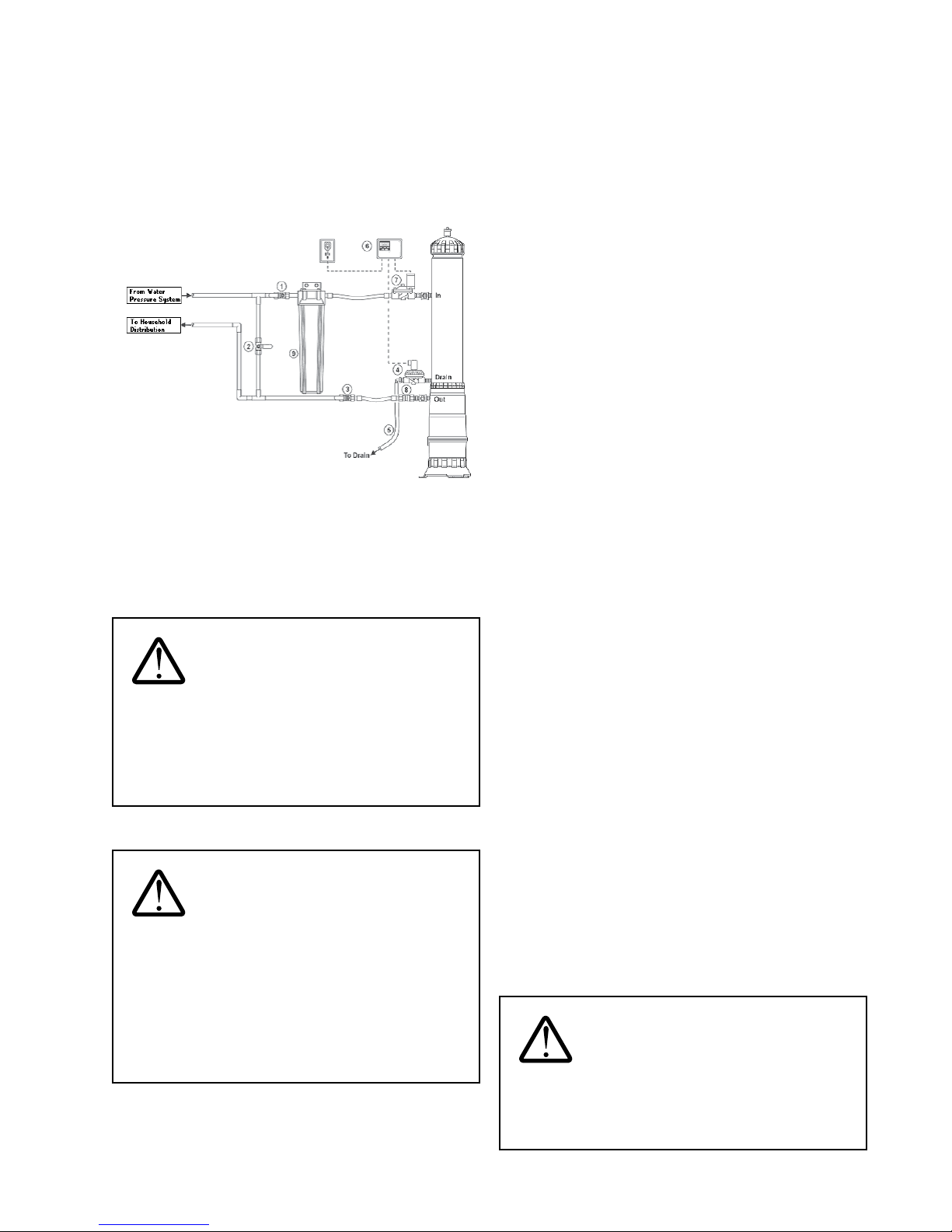
System Conguration for Standard Installations
For households on a municipal system, locate the water
main, which connects the household to the municipal supply
line. Usually this is near the water meter. For private pump/
pressure tank style systems, locate the outlet of the pressure
tank. The system must be installed downstream of the water
meter or pressure tank in order to provide treated water to the
whole household.
The system is installed directly in-line with the home supply,
following the water meter or pump and pressure tank.
Diverted Line for nonfiltered water
outlets.
(e.g. Exterior taps)
1. Inlet Valve
2. Bypass Valve
3. Outlet Valve
4. Drain Solenoid Valve
5. Drain Hose
6. Advanced Plus Controller
24 VDC
System Installation Location with other Water
Treatment Devices
If other water processing devices are currently installed in the
home, the system should be located as shown in the diagram.
Household Faucets
Pressure Ta nk;
Sediment Filter;
Sand Filter;
Water Softener;
Chlorinator
Figure 1
A water softener can be placed either before (upstream) or
after (downstream) the system. If the softener is downstream
of the system, it is recommended that a supply line of hard
water be plumbed to the kitchen so that ltered, mineralized
water can be utilized in food preparation and for human
consumption.
If a chlorinator is used to control bacterial and virus growth in
pipes, a stainless steel prelter may be installed in the system
instead of a carbon prelter.
UV Light
Water Softener
Chlorinator
Figure 2
NOTE: A dedicated line, diverted from the main water line,
may be installed upstream of the system for all exterior taps,
pool or hot tub makeup valves, and irrigation systems. This
arrangement will extend the life of the system membrane.
6
Page 7
System Conguration for Optional Surface
Water Option Kit
Systems purchased with the surface water option kit are
installed at the same location and in the same manner as a
standard system, with the exception of additional parts, which
must be installed, as shown. Additional parts include an inlet
solenoid valve, check valve, and external prelter.
24 VDC
1. Inlet Valve
2. Bypass Valve
3. Outlet Valve
4. Drain Solenoid Valve
5. Drain Hose
6. Advanced Plus Controller
7. Inlet Solenoid Valve
8. Check Valve
9. External Prefilter
Figure 3
NOTE: The inlet solenoid valve of the surface water option kit
creates a non-pressurized draining of the system. The entire
drain line, including the oor drain, must be below the drain
port of the system.
WARNING: When treating surface
water sources, an external prelter of 20-microns
(e.g. Pentek S1-20BB) nominal micron size is required.
Failure to provide this level of preltration may lead to
system damage and will void the warranty. A damaged
system may cause serious personal injury, illness, and/
or death.
Tools, Supplies and Parts
The following list of tools and supplies are required for the
completion of this installation:
Tools (not provided)
• Slip Joint Pliers 12" • Knife
• Pipe Wrench 12" • Air Pump
• Adjustable Wrenches • 1/4" Hex Key
• Torpedo Level • Torch with Gas
• Fine Slot Drivers • Snips
• Phillips Drivers: #0, 1 • Robertson Drivers: #1, 2
• Nut Drivers: 5/16, 3/8 • Masonry Drill with 3/8"
Bit
Supplies Required (not provided)
• Copper Pipe • Pen or Pencil
• Ground Wire • Funnel
• Flux and Flux Brush • Hose Clamps
• Solder (lead free) • Suspension Strap
• Assorted Copper
• Tie Wraps or Cable Ties
Fittings
• Plumber Tape or Pipe
Dope (for potable
water) NSF Approved
• 3 Water Shut-o Valves
(same size as install
piping)
• 5/8" Hose for Drain
(comply with local
plumbing code)
• 2' x 2' Patio Stones
(required only for
heated oor)
• Unscented Chlorine
Bleach (Clorox) - 5-6%
or 12%
Tools Supplied with Integrity Test Kit
• Integrity Tester • Housing Wrench
• Cap Wrench • Two Pressure Gauges
• Silicone Lubricant -
DOW CORNING 111
• Digital Air Pressure
Gauge
• Two 1/4" Tubings
Spare Parts (recommended)
WARNING: Tools used to install the
system should be maintained in sterile condition so that
the risk of cross-contamination is minimized. Bacteria,
parasites, and viruses can live for long periods of
time. As a result, dangerous organisms can be carried
from one installation or maintenance site to another
and may potentially cause serious personal injury,
sickness and/or death. Proper tool care and disinfection
procedures will minimize these risks.
• AA Batteries • O-ring
• Inlet Solenoid Valve • Drain Solenoid Valve
• Air Relief Valve • Advanced Plus
Controller
• Stainless Steel Flex
Hose
• 1/4" Mini Ball Valve
with Plug
• 3/4" Inlet/Outlet Fitting • 1/2" Nipple
WARNING: Ball valves are
recommended for use as the bypass, inlet and outlet
valves. Gate valves have a tendency to leak, allowing
unltered water to mix with ltered water. The result
may cause personal injury, sickness and/or death.
7
Page 8
System Parts List
UFC 211 and UF 211
• System
(pre-assembled)
• System Base • Advanced Plus
• Carbon Prelter • Cap Wrench
• Two Stainless Steel Flex Hoses
Inside the bubble bag:
• 1 - Drain Solenoid Valve
(normally closed)
• 1 - Nylon Elbow • 1 - 1/2" Nipple
• 2 - 1/4" Mini Ball Valves
with Plugs
• 1 - Air Relief Valve • 3 - Shims
• 3 - 3/8" Bolts
Surface Water Kit (optional)
• 1 - External Prelter
Housing
• 1 - Wall Bracket Kit • 1 - Check Valve
• Mounting Screws • 4 - 1/2" Lag Bolts
• 1 - Inlet Solenoid Valve
(normally open)
• Transformer (120VAC)
Controller
• 2 - 3/4" Inlet/Outlet
Fittings
• 3 - 1/4" x 2-1/2"
Anchors
• 1 - 1/4" Mini Ball Valve
with Plug
• 1 - External Prelter
Cartridge (20- micron
nominal)
• Drain within 20' (610 cm) and up to 72" (183 cm) high. If
the system is to be equipped with an inlet solenoid valve,
the drain cannot be higher than the drain port of the
system for proper draining.
NOTE: All outlets downstream of the system will provide
ltered water. A dedicated line, diverted from the main water
line, is recommended to be installed upstream of the system for
all exterior taps, pool or hot tub makeup valves, and irrigation
systems. This set-up will help prolong the life of the system
membrane.
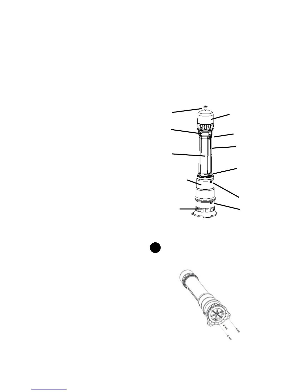
Part Identication
Air Relief Valve
Internal
Prelter
Membrane
Module
Backpulse Tank
System Cap
Inlet port
System Casing
Drain port
Outlet port
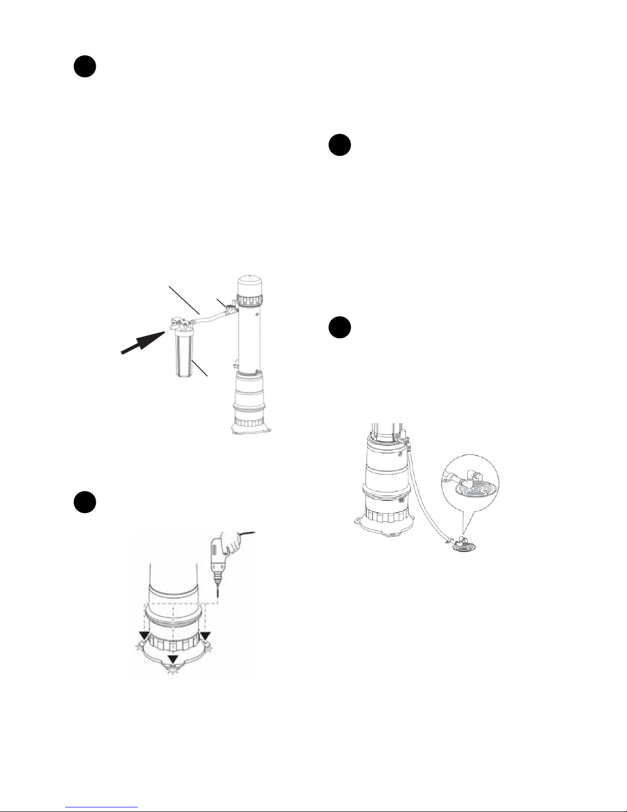
Preparing for Installation
Pre-Installation Inspection
Prior to beginning the installation, check for the following:
• Space near point of entry of water supply
• Footprint and height clearance
Footprint: minimum 18" x 18" (46 x 46 cm)
Height Clearance: minimum 74" (188 cm)
• Indoors with ambient temperature between 40-90°F
(4-32°C)
• Drillable oor, patio stone, or wood base. Patio stone
must be securely anchored to oor
• Electrical outlet, uninterruptable 120VAC, within 6' (182.8
cm)
• Existing water equipment (e.g. water softeners, lters
upstream and UV downstream)
• Recommended household water pressure is 30 psi
minimum. If water pressure is less than 30 psi, adjust
backpulse tank pressure. Refer to Step 4 in the System
Installation section.
System Base
Figure 4
Air Bladder
Valve
System Installation
1
The system is shipped fully assembled, except for the
system base. Attach the system base to the backpulse tank,
using the supplied 3/8" bolts and washers.
Figure 5
8
Page 9
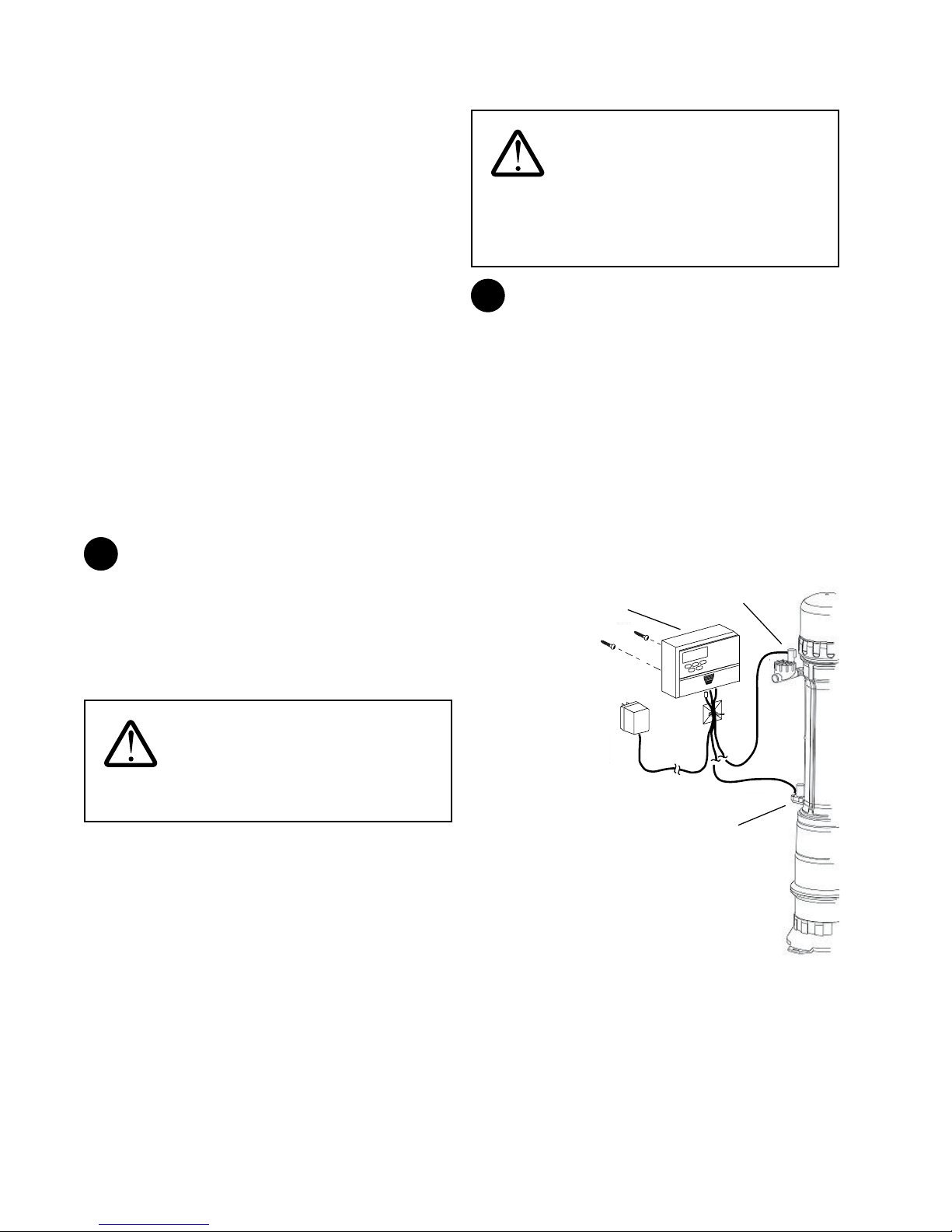
2
Stand the system upright carefully.
NOTE: Cut open the plastic bag before standing the system
upright.
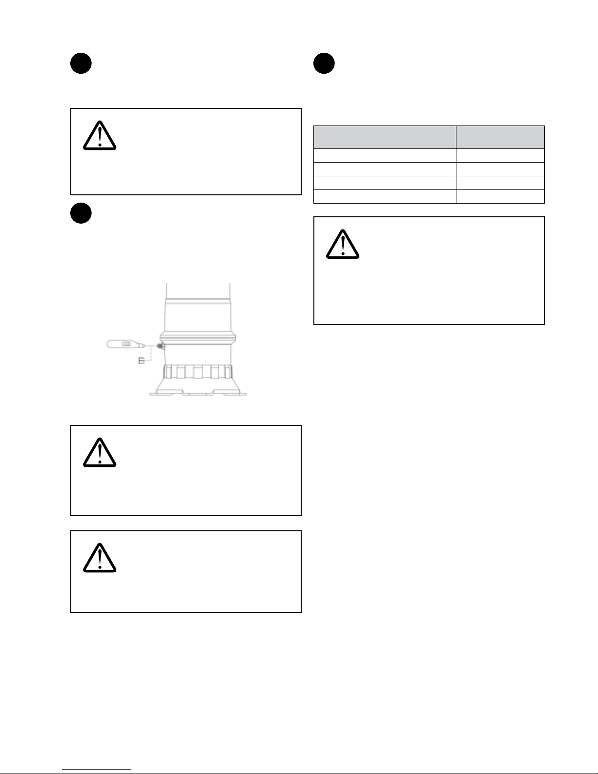
4
The pressure may require adjustment depending on the
water system of the home. Refer to the table below to ensure
proper tank pressure. Air can be added or released from the
air bladder valve as required. Backpulse tank pressure should
be set approximately 5 psi below outlet pressure.
WARNING: Handle the system with
care. The outside surfaces of the system may be
slippery with a food-grade preservative used in the
manufacturing process.
3
The backpluse tank has been pre-pressurized to
approximately 30-35 psi from the factory. Conrm the
backpulse tank pressure. If the backpulse tank pressure is less
than 30 psi, add air using a pump. Recheck the pressure after
15 minutes to ensure that there are no leaks in the backpulse
tank.
Digital Air
Pressure
Gauge
Backpulse
Ta nk
Valve Cap
Figure 6
Application/Pump Set-points Backpulse Tank
Pressure
Municipal 30-35 psi (207 kPa)
Pump (20 psi low - 40 psi high) 20 psi (140 kPa)
Pump (30 psi low - 50 psi high) 30 psi (207 kPa)
Pump (40 psi low - 60 psi high) 30-35 psi (207 kPa)
WARNING: Do not pressurize the
backpulse tank to greater than 35 psi. Higher pressures
may cause the tank's bladder to burst, leading to
ineective daily cleaning. Ineective cleaning can
greatly reduce the life of the system, leading to
personal injury, illness, and/or death.
Once the backpulse tank pressure is checked, adjusted, and
set, record nal pressure on the service tag and on Page 3 of
this Manual.
WARNING: The Homespring base
must be used and securely anchored. Failure to do so
may result in damage to the system and will void all
warranties.
WARNING: Be sure to always verify
and set backpulse tank pressure. The Homespring
system must be empty when checking pressures.
9
Page 10
Outlet port
Pipe Assembly and Installation
Ensure that all threaded connections are tted with NSF
approved plumber tape or pipe dope (for potable water) to
prevent leakage.
For systems being installed on surface water applications, the
surface water kit must be installed.
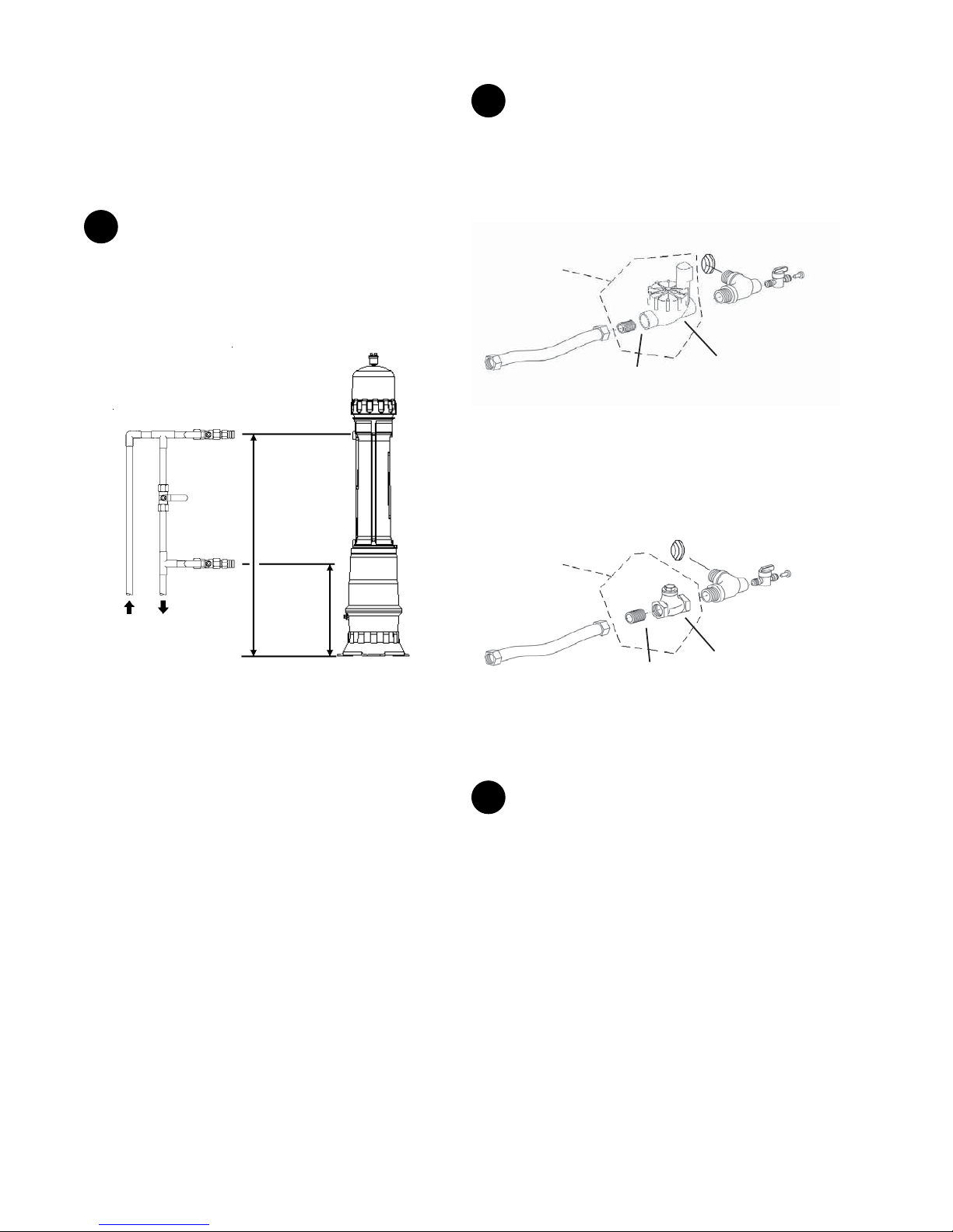
1
Turn o water supply where the water enters the home.
Plumb the inlet pipe at approximately 48" (122 cm) and the
outlet pipe at approximately 20" (50 cm) o the ground. Install
water shut-o valves on the new plumbing. The terminal ends
of the new plumbing must be a 3/4" MNPT adapter in order to
use the supplied stainless steel ex hoses.
2
The two inlet/outlet tting assemblies are shipped
pre-assembled, with the mini ball valves and plugs already
installed. Ensure that the plumber tape at both threaded ends
are in good condition. Assemble the inlet and outlet tting
assemblies as shown.
Inlet Fitting Assembly
For models
equipped with
Surface Water
Option Kit only
Inlet port of
System
Mini Ball Valve
with Plug
Inlet/Outlet
Fitting
Inlet Valve
Inlet 48”
Bypass
(122cm)
Valve
(optional)
Outlet
Valve
Outlet 20”
(51cm)
Figure 7
NOTE: The water bypass in the gure only bypasses the
system. This conguration may be required according to the
local plumbing code in your area.
Stainless Steel
Flex Hose
3/4” MNPT
Nipple
Inlet Solenoid
Valve
Figure 8
The directional arrow on the inlet solenoid valve must point in
the direction of the water ow.
Outlet Fitting Assembly
For models
equipped with
Surface Water
Option Kit only
Stainless Steel
Flex Hose
of System
3/4” MNPT
Nipple
Check
Valve
Mini Ball Valve
with Plug
Inlet/Outlet
Fitting
Figure 9
The directional arrow on the check valve must point in the
direction of the water ow.
3
Install the drain solenoid valve (normally closed) to the
1/2" nipple to the drain port of the system. The directional on
the drain solenoid valve must point in the direction of the
water ow (i.e. away from the system). Install the nylon elbow
to the ow exit port of the drain solenoid valve.
10
Page 11
4
Applicable to Systems in Non-Surface Water
Applications Only:
Connect the inlet and outlet tting assemblies to the 3/4"
MNPT ends of the new plumbing with the supplied stainless
steel ex hoses.
Applicable to Systems Equipped with the Surface Water
Option Kit Only:
Select a location on an adjacent wall, with adequate support
(e.g. wall studs), between the stainless steel ex hose of the
inlet tting assembly and the inlet line of the new plumbing.
Follow the instructions described under the Surface Water
Option Kit Installation section in this manual to install the
external prelter. Connect the stainless steel ex hose on the
inlet tting assembly to the external prelter. Once nished,
connect the external prelter to the 3/4" MNPT end of the new
inlet plumbing.
Stainless Steel
Flex Hose
To ¾” MNPT end of
the new Inlet
plumbing
Inlet
Solenoid
Valve
External
Prefilter
the system to the oor with the supplied 1/4" x 2-1/2" anchors
(for concrete oor) or use screws (not supplied) for wood oors.
NOTE: If the system is being installed on a heated oor, use a
2' x 2' patio stone, that is securely anchored to the oor, for a
base. Do not drill the oor.
6
Apply plumber tape to the 1/4" threads on the air relief
valve. Using a hex key, remove the plug that is located at
the top of the system cap. Thread the air relief valve into the
opening. Do not use tools to tighten the air relief valve to the
system cap as it may cause damage. Loosen the black cap of
the air relief valve 1-1/2 turns to allow for proper venting. Do
not use pliers to take out plugs.
Inlet Fitting Assembly:
Follow the instructions in the Pipe Assembly and Installation
section to assemble the inlet tting assembly. If the surface
water option kit is installed, rotate the inlet solenoid valve
right-side-up.
Final Plumbing Assembly
1
Fasten a drain hose to the nylon elbow of the drain
solenoid valve. Run the drain hose to a oor drain, sink or
dedicated drain that can accommodate the pressure and ow
created during a ush/drain cycle. The drain hose must be free
of kinks and leaks. Fasten the hose to the oor or wall and
direct the hose into the drain with an elbow or clamp. Ensure
that the drain hose can withstand the pressure of the home’s
water supply.
Figure 10
Connect the stainless steel ex hose of the outlet tting
assembly to the 3/4" MNPT end of the new outlet plumbing.
5
Securing to the oor. Drill a 3/8" hole through the feet of
the system base.
Figure 11
To level the system, insert the supplied shims beneath the feet
of the system base. Check with a level. Once leveled, fasten
The local plumbing
code may require
an air gap to be
installed at the
drain line.
Drain hose must be
anchored down to the
floor or wall and
directed down into the
drain
Figure 12
All systems will have a pressurized ush sequence during the
cleaning cycle. Depending on the controller program selected,
the system may also have a draining sequence. Refer to the
Setting the Controller section for detailed information on
ushing and draining cycles. The following are recommended
drain line discharge set-ups for the systems.
NOTE: Drain conguration must comply with the local
plumbing codes.
For Systems That Have Only Flushing Sequences (Program
11
Page 12
1 or 2):
The oor drain and/or drain hose may be raised above the
drain port of the system. The entire drain line must be leakproof, The oor drain does not have to be in the same room as
the system.
As an alternative, the system may be drained directly into a
laundry tub. The laundry tub is usually above the drain port of
the system.
For Systems That Have Both Flushing and Draining
Sequences (Program 3 or 4):
The draining sequence is non-pressurized. Because the system
is completely emptied under only atmospheric pressure during
the draining sequence, the entire drain line, including the oor
drain, must be below the drain port of the system.
NOTE: Systems installed in surface water applications must
have ushing and draining cycles.
Dedicated Trap Drain:
The trap drain must be installed in accordance with local
plumbing regulations. Ensure that there is an adequate air gap
between the drain and the main discharge line. If a dedicated
trap drain is installed in a system that undergoes both
draining and ushing cycles, ensure that the dedicated trap
drain is below the drain port of the system.
2
The cold water pipe is often used to ground electrical
outlets inside the dwelling. If grounding connection(s) to the
cold water line exists downstream of the system, the
grounding path might have been broken after this installation.
To restore the grounding path, attach a ground wire across
the inlet and outline lines of the system. Refer to the local
electrical code for the ground wire gauge, ground wire
material, and connection method requirements.
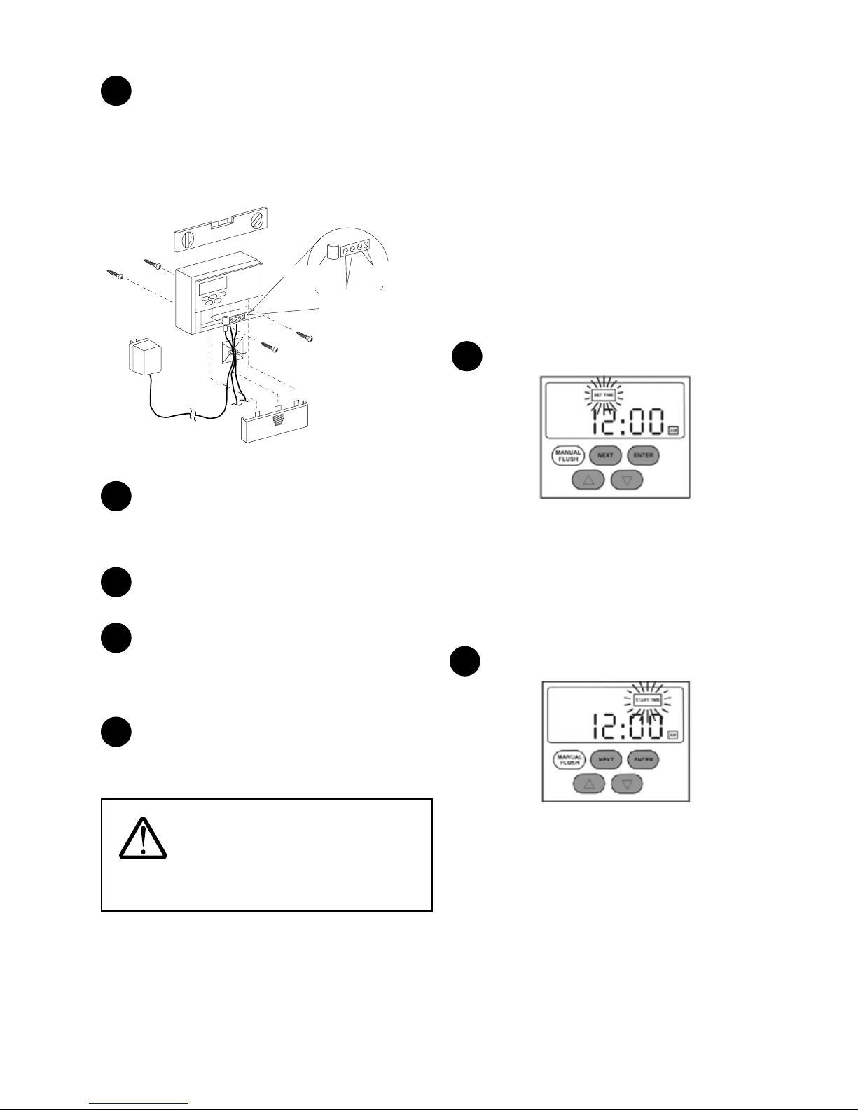
Installing the Controller
WARNING: To ensure personal safety
and that the internal fuse in the 24 VDC transformer is
not blown during installation, install the plug from the
transformer into the controller terminals labeled 24
VDC before plugging the transformer into an outlet.
1
Use the provided plastic anchor if necessary. Ensure that
the controller is within the proximity of the system so that the
cables can reach the drain solenoid valve and the inlet
solenoid valve (for systems equipped with the surface water
option kit only).
Drill a hole suitable for a #8 screw on an adjacent wall. Insert a
#8 screw in this hole and tighten the screw, leaving a 1/4" gap
between the screw head and the wall. Drill a hole suitable for
a #8 screw on an adjacent wall. Insert a #8 screw in this hole
and tighten the screw, leaving a 1/4" gap between the screw
head and the wall.
The transformer cable should also be long enough to reach
the electrical receptacle. Do not connect any cables at this
time.
Inlet Solenoid
Controller
Valve
WARNING: Grounding protects home
occupants from electrical shock. Broken grounding
may cause personal injuries and/or death.
12
Transformer
Drain Solenoid
Valve
Not-To-Scale
Figure 13
Page 13
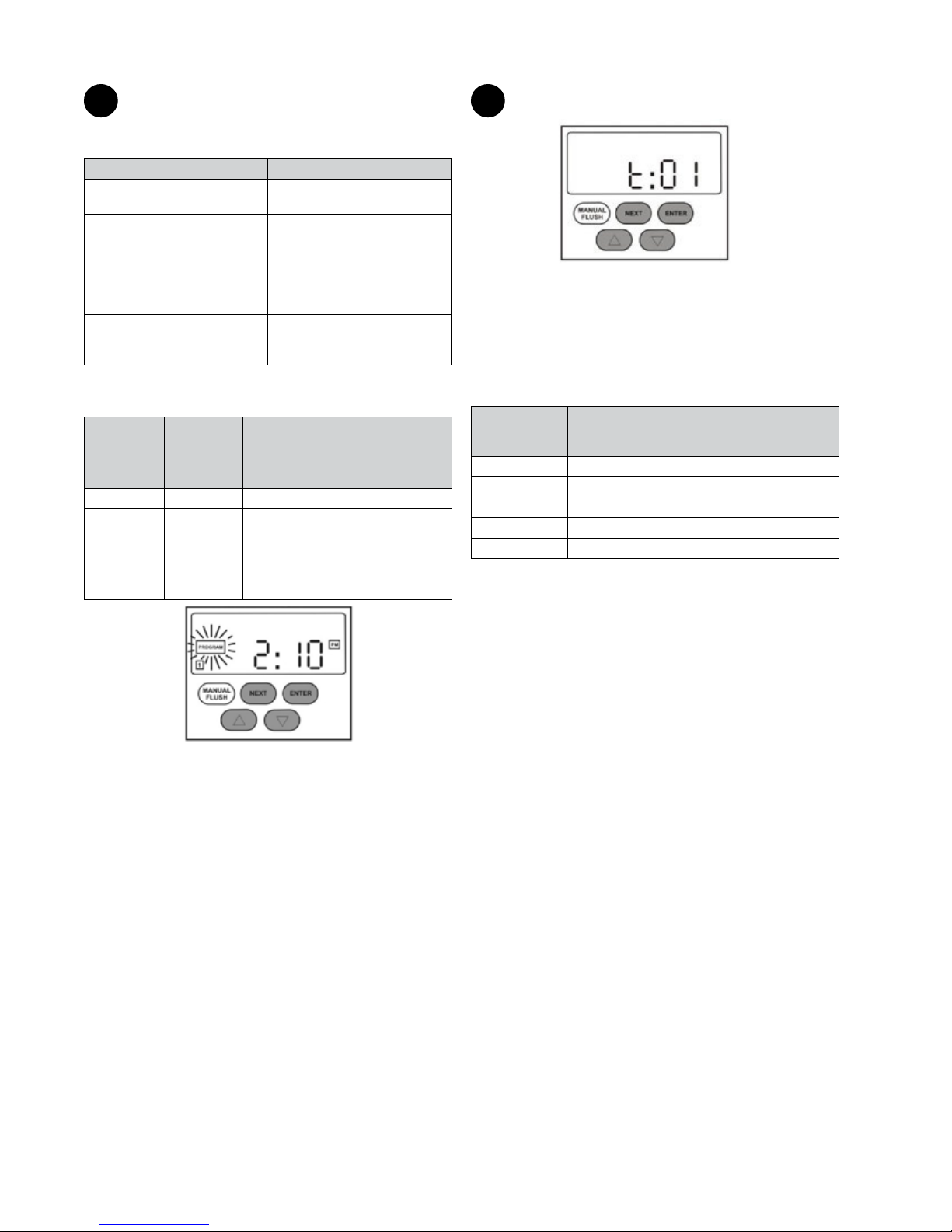
2
Mount the controller using the keyhole located at the
back of the controller on the screw head. Level the controller.
Remove the controller front cover and drill two additional
holes suitable for a #8 screw into these two holes and secure
the controller to the wall by tightening the two screws. Use the
plastic anchors if necessary.
Advanced
Plus Controller
24 VDC from
Transformer
Solenoid Valve
To Drain
To Inlet
Solenoid Valve
Figure 14
Setting the Controller
NOTE: Electrical power to the controller must be ON to
activate the ushing and draining sequences. The batteries
are for keeping the time in case of power failure and will not
activate the ushing and draining sequences.
NOTE: Once the controller is set, the controller will remember
the start time, program number, and ush/drain interval
settings (if applicable) even if the electrical power to the
controller is interrupted.
NOTE: When the system is undergoing a ushing or a draining
sequence, very little or no water will be available for use in the
dwelling. If possible, select a time for the ushing and draining
when no water generation is required. Normal operation will
resume once the ushing and draining sequences are nished.
Follow these steps to set the Controller:
Setting the Clock
1
3
Ensure the transformer is not plugged into the electrical
receptacle. Connect the power supply cable from the
transformer to the 24 VAC terminals on the controller. Polarity
is not important.
4
Connect the drain solenoid valve cable to the “drain”
terminals on the controller. Refer to Figure 14.
5
Applicable to Systems Equipped with the Surface
Water Option Kit Only:
Connect the inlet solenoid valve cable to the “inlet” terminals
on the controller. Refer to Figure 14. Polarity is not important.
6
Install the two AA batteries (provided) in the controller.
Replace the controller front cover and plug the transformer
into the electrical receptacle.
WARNING: Use only the supplied
electrical transformer. Failure to follow this instruction
will void the warranty.
Figure 15
1) Press NEXT twice until “SET TIME” ashes on screen.
Press ENTER.
2) Press the UP and DOWN arrows to set the hour. Press
ENTER.
3) Press the UP and DOWN arrows to set the minute. Press
ENTER.
Setting Flush/Drain Time
2
Figure 16
1) Press NEXT three times until “START TIME” ashes on
screen. Press ENTER.
2) Press the UP and DOWN arrows to set the hour. Press
ENTER.
3) Press the UP and DOWN arrows to set the minute.Press
ENTER.
NOTE: Check with homeowner. Select a time of day that
water usage is not expected in the dwelling. (e.g. 2:00 a.m.). The
controller will store this setting.
13
Page 14
Setting the Program
3
Choosing a program:
Water Clarity Advanced Plus Controller
Low Turbidity
Less than 0.5 NTU
Medium Turbidity
Peaks to 1.0 NTU, less than 72
min. per day
High Turbidity
Peaks to 5.0 NTU, less than 72
min. per day
Very High Turbidity
Peaks to 10.0 NTU, less than 72
min. per day
Program 1
Program 2
Program 3
Program 4
NOTE: If surface water is the source, select either Program 3
or Program 4 in this application.
Advanced
Plus
Controller
Program 1 2 ushes 2.5 min 7.5 gal
Program 2 4 ushes 6 min 15 gal
Program 3
Program 4
Cleaning
Sequence
2 ushes & 1
drain
2 ushes & 2
drains
Duration
8.5 min 13.5 gal
16.5 min 19.5 gal
Approx Water
Consumption Per
Cleaning Cycle at 5
gpm
Setting the Flush/Drain Interval:
4
Figure 18
1) Press NEXT ve times until “t:01” appears on screen.
2) To change the ush/drain interval setting, press and
hold the UP and DOWN arrows together and press
NEXT. Release all buttons and repeat to shift to the next
interval. There are ve interval settings to choose from:
Flush/Drain
Interval Setting
t:01 1 time 24 hrs
t:02 2 times 12 hrs
t:04 4 times 6 hrs
t:08 8 times 3 hrs
t:24 24 times 1 hr
No. of
Flush/Drain Cycles
per Day
Time Interval Between
Flush/Drain Cycles
NOTE: Under conditions of turbid water and high usage of
the system, select a ush/drain interval setting appropriate
to the specic application. Increase frequency of ush/drain
cycle if the system TMP rises too quickly. Increasing the
number of ush/drain cycles per day will prolong the life of the
system; however, more water will be used for system cleaning
purposes.
Figure 17
1) Press NEXT four times until “PROGRAM” ashes on
screen. Press ENTER.
3) Press the UP and DOWN arrows to set the Program
number. Select the appropriate Program for your
application. Press ENTER.
14
Page 15
Controller Functions
A. Manual Flush
NOTE: For use when the instructions in this manual or the
Owner's Manual call for a manual ush.
To manually ush the system, press NEXT once. “MANUAL”
ashes on the screen. Press MANUAL FLUSH to open the drain
solenoid valve. If the MANUAL FLUSH button is held down for
5 seconds, the drain solenoid valve will remain open for 5
minutes. To interrupt ushing, press MANUAL FLUSH again.
The drain solenoid valve will be closed automatically after 5
minutes if not interrupted.
B. Light and Alarm Function:
The green light on the controller indicates that the system is in
operation. The green light will be ON for 10 months from the
rst commissioning of the system.
WARNING: The green light is NOT an
indication of the integrity of the membrane inside the
system.
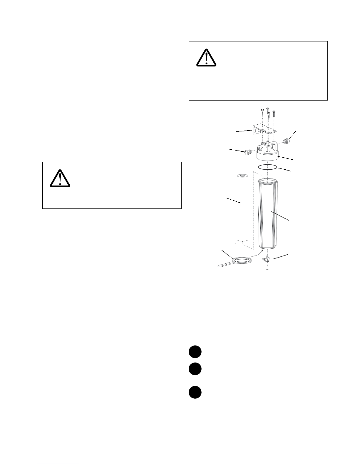
Surface Water Option Kit Installation
WARNING: For all surface water
installations, the Homespring Certied Technician must
inform the homeowner and home occupants that the
entire water supply and distribution system of the
dwelling must be disinfected prior to use.
1” x ¾”
Wall
Bracket
1” x ¾”
MNPT
Adapter
External
Prefilter
cartridge
MNPT
Adapter
External
Prefilter
head
O-ring
At the start of the system’s 11th month of operation, the
yellow service indicator light will come on. This is an indication
that the system’s annual maintenance is required.
After 11½ months of operation, the yellow service indicator
light will begin to ash and an audible alarm will start to beep.
To temporarily silence the alarm, depress and hold the UP and
DOWN arrows together for three seconds. The alarm will come
back on in seven days after this command is executed.
To permanently turn the alarm o, depress and hold the UP
and DOWN arrows together and press ENTER. “A oF” (alarm
o) will appear on the screen. To turn the alarm on again,
repeat the above step. “A on” (alarm on) will appear on the
screen.
To reset the controller, press NEXT and ENTER together and
hold for three seconds. The yellow light will go o and the
green light will come on again.
External
Prefilter
housing
Housing
Wrench
Mini Ball
Valve
with Plug
Figure 19
The surface water kit is purchased separately from the system.
Install this kit in surface water applications.
For convenience of servicing, install the external prelter
between the inlet valve and the inlet tting assembly.
The inlet solenoid valve (normally open) must be installed
as part of the water inlet line and the check valve must be
installed as part of the water outlet line. Refer to Step 2 in the
Pipe Assembly and Installation section.
1
Mount the wall bracket to the wall.
2
Attach the external prelter head to the wall bracket
using the four supplied lag bolts.
3
Remove the plastic wrap on the external prelter
cartridge and insert the cartridge into the external prelter
housing.
15
Page 16

4
Ensure that the O-ring is seated at the lip of the external
prelter housing. Screw the external prelter housing into the
external prelter head. Tighten the connection with the
housing wrench.
5
The plumbing must be compatible with the inlet and
outlet ports of the external prelter.
6
Install the mini ball valve with plug at the bottom of the
external prelter housing.
When external prelter housing needs to be removed for
servicing (e.g. to change the lter cartridge), close the inlet
valve and depressurize the external prelter by draining the
water inside. To drain the water inside, open the mini ball valve
at the bottom of the external prelter housing. Depress the
red button on the external lter head to speed up draining. A
length of 1/4" tubing can be inserted into the port of the mini
ball valve to direct water into a drain or a large pail.
NOTE: Before installing or replacing the external prelter
housing on the external prelter head, inspect the O-ring to
ensure that it is clean and in good condition. Lubricate the
O-ring sparingly with DOW CORNING 111 silicone lubricant.
D. commissioning - vertical
WARNING: The system must be lled
with water at all times once commissioned. Failure
to do so may cause the system to dry and become
damaged, resulting in personal injury, illness, and/or
death.
Do not turn on any hot water taps when ushing the
system during commissioning or maintenance. If
hot water is used, high levels of factory preservative,
chlorine, or MC1 cleaning agent may enter the hot
water tank and may cause personal injury, illness, and/
or death.
Disposable protective gloves must be worn during
commissioning of the system to protect your hands. At
the end of the procedure, wash your hands thoroughly
with soap and water. Do not reuse gloves. Dispose of
gloves in the garbage.
Filling and Flushing
WARNING: In surface water
applications, failure to install and/or properly maintain
the external prelter cartridge may cause premature
fouling of the system and therefore, shorten the
system’s life or damage the system membrane, causing
personal injury and/or death.
WARNING: If the system cap is not
properly tightened and/or the O-ring is not clean,
system leaks may occur. Leaks may cause personal
injury or property damage. Take care not to crossthread the system cap during cap installation. Apply
DOW CORNING 111 silicone to O-ring and threads. Spin
system cap by hand until it stops. Then tighten with
supplied wrench 1/2 turn. If cap leaks, turn o water
and turn additional 1/4 turn. Make sure vent valve is
always open 1-1/2 turns to allow trapped air to escape
freely.
When the internal prelter is removed, ensure the
thimble lter remains in place, seated in the spigot of
the prelter cavity. Removal of the thimble lter may
permit damage to the system membrane, which may
lead to illness or death.
16
Page 17

1
Remove the system cap and remove the internal
prelter. Place the internal prelter in a clean, dry area. Ensure
that the thimble lter is seated properly. Replace the system
cap and tighten as described above.
For models with a stainless steel prelter, a carbon prelter
may be purchased separately if desired.
Make sure vent valve is loose (1-1/2 turns).
3
Using the controller, initiate a manual ush sequence.
Refer to the instructions in the Controller Functions section on
how to perform a manual ush sequence. Following the
manual ush, open a cold water tap that is downstream of the
system. Allow water to ow for 15 minutes. The system
requires a 15-minute ush to remove the food-grade factory
preservative.
Cleaning
Internal
Open
Close
Figure 20
2
Slowly open the inlet valve half way, allowing water into
the system. Avoid opening the inlet valve quickly as this will
introduce air pockets that will take longer to escape. Keep the
outlet valve closed. Check for any leaks in the plumbing. If
present, close the inlet valve immediately and repair. As
pressure builds in the system air will begin to escape from the
air relief valve. Once air is no longer passing through the air
relief valve, the system is pressurized.
Prefilter cavity
Inlet valve
Outlet valve
Figure 21
If an external prelter is installed, depress the red button on
the external prelter head to allow air to escape from the
external prelter housing. Once water emerges from the
button, all air has been removed.
1
Ensure that the two mini ball valves are closed (to close,
turn the handle perpendicular to the plug/hose end). Remove
the plug from the two mini ball valves by depressing the lock
ring and pulling on the plug. Insert a pressure gauge from the
integrity test kit into the inlet mini ball valve, open valve and
observe system pressure.
The valve is OPEN when
handle is in the position
shown
lock
ring
Figure 23
2
Close the inlet and outlet valves, leaving the inlet mini
ball valve open. Using the controller, initiate a manual ush
sequence to bring system pressure to zero. Refer to the
instructions in the Controller Functions section under on how
to perform a manual ush sequence. Once the pressure gauge
registers zero pressure, stop the manual ush immediately.
3
Remove the system cap using the cap wrench. The
water level should be at least 2" above the internal prelter
spigot.
If the water level is below 2", open the inlet valve slowly to
raise the water level.
Figure 22
Figure 24
4
With the internal prelter still removed, pour 2 cups
(500 ml) of 5 - 6% unscented household chlorine bleach
(Clorox) OR 1 cup (250 ml) of 12% chlorine bleach into the
prelter cavity. Replace the system cap. Slowly open the inlet
valve to pressurize the system. Let stand for 15 minutes.
17
Page 18

5
Using the controller, activate the manual ush sequence.
Refer to the instructions in the Controller Functions section on
how to perform a manual ush sequence. Run manual ush
2-3 times then proceed to ush thru tap. Once the ushing is
complete, open the outlet valve and a nearby COLD water tap
to ush most of the chlorine from the system. Run the tap fully
open for at least 10 minutes. Further ushing must be
performed by the homeowner later. Refer to the Final Flush by
Homeowner section.
NOTE: Use only COLD water taps and continue the ow of
water until there is no chlorine smell.
Integrity Test
Purpose
This test ensures that the membranes are intact and free
from tears or ruptures that would permit bacteria and other
particles to pass through the membranes, contaminating
the ltered water. The integrity test is conducted at initial
commissioning after the 15-minute ush and subsequent
sanitization and on an annual basis by a Homespring qualied
technician.
Test Description
This automated test will pressurize the membranes with air
from the outlet side of the system, forcing clean water back
through the membranes. Water easily passes through the
membranes due to the surface tension of water, however air
has a dierent surface tension and does not normally pass
through an intact membrane. Once adequate air pressure
has been achieved, a pressure sensor measures any decay of
that pressure. The integrity tester analyzes the pressure data
over this interval. If the decay is within acceptable limits the
integrity tester will indicate a ‘PASS’.
Tools Required
• Integrity tester • Cap wrench
• 2 lengths - 1/4" tubing • 2 - Pressure gauges
• 2 cups (500 ml) of unscented household chlorine
bleach (Clorox)
Other than the sanitizers, all required tools are included in the
service kit.
NOTE: A bucket may be required to collect some water if the
1/4" tubing is not long enough to reach a drain.
Disinfection Procedure for Tools
All pressure gauges and tubing MUST be disinfected prior
to use to avoid cross-contamination and introduction of
contaminated water into the household system.
Place and soak the adaptor tip and the 1/4" tubing ends in
5-6% unscented household chlorine bleach (Clorox) for 5
minutes. The brass adaptor will tarnish with time but this is
acceptable. Do not submerge the entire pressure gauge into
the sanitizer as it may damage it’s internal components. See
Figure 25.
Figure 25
1
Close inlet and outlet valves. Use the controller to
initiate a manual ush sequence to bring the system pressure
to zero. Refer to the instructions in the Controller Functions
section on how to perform a manual ush sequence. Insert
pressure gauges into the inlet and outlet mini ball valves and
open the valves. Conrm that the system pressure is zero.
Figure 26
2
Close the inlet mini ball valve (Figure 27), remove the
pressure gauge. Insert 1/4" tubing into the inlet mini ball
valve. Direct this tubing to a drain or a pail, and reopen the
inlet mini ball valve. Plug one end of the second 1/4" tubing
into the outlet mini ball valve and the other end into the
integrity tester.
18
Page 19

1/4”
tubing
Inlet
Valve
Inlet Mini
Ball
Valve
If a pass is indicated then the system integrity is good and it is
possible to proceed to the next step.
Integrity Test Fault
Drain
Solenoid
Valve
Outlet
Valve
Drain
Integrity
Te ster
Transformer
Integrity
Tester
1/4”
tubing
Outlet
Mini Ball
Valve
Figure 27
3
Plug the integrity tester into a power supply. Press the
scroll keys until the screen displays "Integrity Test". Press
ENTER and use the scroll keys to choose “Vertical”.
Figure 28
4
Open the outlet mini ball valve and press the ENTER key
on the integrity tester to begin the test. The integrity tester will
automatically proceed through all test steps.
5
The integrity test will take approximately 8 minutes to
complete for a vertical system. At the end of the test, one LED
indicator will light.
The possible test results are:
• Green LED - PASS
• Yellow LED - FAULT
• Red LED - FAIL
WARNING:
When performing a
Membrane Integrity Test there can be several causes
for a false failure, such as leaks in ttings and/or tubing
connections. Be sure to troubleshoot and verify if you have
a failed Membrane Integrity Test. Call technical service
before conrming a failed Membrane Integrity Test.
If a FAULT or FAIL is indicated, perform the integrity test again.
To repeat, CLOSE all mini ball valves. Open the inlet and outlet
valves and run a tap for 5 minutes. Begin again from Step 1.
Repeat the integrity test at least three times before assuming
that there is a fault within the system.
NOTE: If there is a FAIL, the most common cause is a leak
in the system from hoses, connections or a valve. Be sure
that all connections are tight before beginning the test and
the inlet and outlet valves are closed. Leaky valves and loose
connections will cause a FAIL.
If a FAULT yellow LED occurs during a test , a fault description
will appear. The following are potential notications with
corresponding corrective actions:
Error Displayed Corrective Action
System pressure high, release
pressure
Open bottom JG valve Outlet mini ball valve is closed.
Pressure failed to rise Leaks in test set-up. Check for
Failed to reach test pressure Test pressure was never
Leak detected Test pressure was never
Failed to stabilize Test pressure was never
System pressure is too high.
Refer to Step 6 to release
pressure.
Open valve and restart test.
leaks.
reached. Check for leaks.
reached. Check for leaks.
reached. Check for leaks.
NOTE: If there is no water coming out from any tap after the
integrity test, check to ensure that both the inlet and outlet
valves have been reopened. Leave the tap running for a few
minutes to allow water ow to return to normal.
Following a FAULT yellow LED notication, take the appropriate
corrective action and re-do the integrity test.
19
Page 20

6
Ensure that the inlet valve is still in the closed position.
Once a PASS green LED is achieved, close all mini ball valves
and remove both 1/4" tubings from the mini ball valves. Open
the outlet valve and turn on a tap downstream of the system
to relieve the air pressure inside the system. Turn o the tap
once water stops coming out.
Insert plugs back into the inlet and outlet mini ball valves.
Once the system has been depressurized, remove the system
cap. Using the controller, perform a manual ush to drain
the prelter cavity so that the spigot at the bottom can be
observed. Refer to the instructions in the Controller Functions
section on how to perform a manual ush sequence.
To Release Pressure:
This procedure is to be used if the following message is
encountered when commissioning the system: “System
Pressure High, Release Pressure”.
This step is to be completed after the system is depressurized
and before the integrity test is done a second time, between
steps 1 and 2 in the integrity test step.
A. Close the outlet JG valve.
B. Disconnect the hose from the integrity tester.
C. Point the hose towards a drain or empty bucket and open
the outlet JG valve.
D. Keep the valve open until all the air has left the unit, a
steady slow stream of water should be owing out of the
hose.
E. Close the JG valve.
F. Re-attach the hose to the integrity tester and restart the
integrity test.
7
Remove the system cap using the cap wrench. Insert the
clean internal prelter into the system prelter cavity. Push
down gently to ensure it is seated properly.
8
Replace the system cap and open the inlet valve. Turn on
a cold water tap to remove any remaining air and residual
chlorine from the system and plumbing. Once the remaining
air is released, leave the tap on for the rest of this procedure.
Transmembrane Pressure (TMP) Test
WARNING: TMP is an indicator of
pressure loss through the system. This includes the
internal prelter, the thimble lter and the membranes.
Be sure the internal prelters and the thimble lter are
clean so that you will get a true representation of the
TMP of the membranes.
The TMP test measures the pressure drop across the
membrane. This is the pressure change that the homeowner
will observe as a result of the ltering process. The TMP is
tracked during the life of the system and is used to determine
the condition of the system membrane. As the membrane
fouls, the TMP will increase.
1
Insert a pressure gauge into each of the inlet and outlet
mini ball valves and open the valves.
Figure 30
2
With a nearby tap running with a high ow rate, read the
two pressure gauges and subtract the outlet pressure from
the inlet pressure. The resulting value is the TMP. Record the
value on the service tag.
When a pump/pressure tank is in use, use the following inlet
pressures to determine TMP:
Inspect and clean
thimble filter as needed.
Figure 29
20
Set Points (psi) Inlet Pressure (Psi)
20/40 35
30/50 45
40/60 55
X/Y Y-5
Page 21

Complete Paperwork
Water Inlet to the House Filtered Water to
The following documents are shipped with the system:
• Owner’s Manual • Service Tag
• Congratulations Letter • Warranty Card
• Pipe Labels • Installation Checklist
Important:
• Complete all info on the service tag and hang from
system cap.
• Complete and return the installation/registration
checklist, ensure that all elds are complete, including
the homeowner’s signature.
• Record the model number on page 3 of this Manual for
future reference.
Final Flush by Homeowner
Have the homeowner continue to run a cold water tap for 60
minutes. This is required to meet NSF drinking water standards
and to remove residual chlorine. The homeowner may notice
chlorine taste/smell when a tap is rst opened for a day or two
following the cleaning procedure.
E. INSTALLATION INSTRUCTIONS HORIZONTAL
All sales, commissioning and maintenance personnel are
required to participate in a Homespring Certied Technician
training program to ensure that they have been trained to
maintain and diagnose the system. Since the primary usage
of the system is to remove bacteria, certain parasites, and
certain viruses from drinking water sources, this certication
program is important and mandatory for both safety and
liability reasons.
All eorts must be made to ensure that installations are
performed in a careful, sanitary manner for the safety of the
homeowner, home occupants, and technicians.
The following section outlines the installation procedures,
the tools required in the installation, and the commissioning
procedures.
NOTE: The images in this manual may appear slightly dierent
than the actual system or parts.
WARNING: To reduce the risk of
severe injury, illness, death and/or property damage,
read and follow all instructions. Use only factory
supplied parts, where required.
System Installation Location with other Water
Treatment Devices
If other water processing devices are currently installed in the
home, the system should be located as shown in the diagram.
Household Faucets
Pressure Ta nk;
Sediment Filter;
Sand Filter;
Water Softener;
Chlorinator
Figure 31
A water softener can be placed either before (upstream) or
after (downstream) the system. If the softener is downstream
of the system, it is recommended that a supply line of hard
water be plumbed to the kitchen so that ltered, mineralized
water can be utilized in food preparation and for human
consumption.
If a chlorinator is used to control bacterial and virus growth in
pipes, a stainless steel prelter may be installed in the system
instead of a carbon prelter.
UV Light
Water Softener
Chlorinator
21
Page 22

System Conguration for Standard Installations
For households on a municipal system, locate the water
main, which connects the household to the municipal supply
line. Usually this is near the water meter. For private pump/
pressure tank style systems, locate the outlet of the pressure
tank. The system must be installed downstream of the water
meter or pressure tank in order to provide treated water to the
whole household.
The system is installed directly in-line with the home supply,
following the water meter or pump and pressure tank.
Diverted Line for nonfiltered water
outlets.
(e.g. Exterior taps)
1. Inlet Valve
2. Bypass Valve
3. Outlet Valve
4. Drain Solenoid Valve
5. Drain Hose
6. Advanced Plus Controller
Figure 32
NOTE: A dedicated line, diverted from the main water line,
may be installed upstream of the system for all exterior taps,
pool or hot tub makeup valves, and irrigation systems. This
arrangement will extend the life of the system membrane.
24 VDC
System Conguration for Optional Surface
Water Option Kit
Systems purchased with the surface water option kit are
installed at the same location and in the same manner as a
standard system, with the exception of additional parts, which
must be installed, as shown. Additional parts include an inlet
solenoid valve, check valve, and external prelter.
24 VDC
1. Inlet Valve
2. Bypass Valve
3. Outlet Valve
4. Drain Solenoid Valve
5. Drain Hose
6. Advanced Plus Controller
7. Inlet Solenoid Valve
8. Check Valve
9. External Prefilter
Figure 33
NOTE: The inlet solenoid valve of the surface water option kit
creates a non-pressurized draining of the system. The entire
drain line, including the oor drain, must be below the drain
port of the system.
WARNING: When treating surface
water sources, an external prelter of 20-microns
(e.g. Pentek S1-20BB) nominal micron size is required.
Failure to provide this level of preltration may lead to
system damage and will void the warranty. A damaged
system may cause serious personal injury, illness, and/
or death.
22
Tools, Supplies and Parts
WARNING: Tools used to install the
system should be maintained in sterile condition so that
the risk of cross-contamination is minimized. Bacteria,
parasites, and viruses can live for long periods of
time. As a result, dangerous organisms can be carried
from one installation or maintenance site to another
and may potentially cause serious personal injury,
sickness and/or death. Proper tool care and disinfection
procedures will minimize these risks.
Page 23

The following list of tools and supplies are required for the
completion of this installation:
Tools (not provided)
• Slip Joint Pliers 12" • Knife
• Pipe Wrench 12" • Air Pump
• Adjustable Wrenches • 1/4" Hex Key
• Torpedo Level • Torch with Gas
• Fine Slot Drivers • Snips
• Phillips Drivers: #0, 1 • Robertson Drivers:#1, 2
• Nut Drivers: 5/16, 3/8 • Masonry Drill with 3/8"
Bit
Supplies Required (not provided)
• Copper Pipe • Pen or Pencil
• Ground Wire • Funnel
• Flux and Flux Brush • Hose Clamps
• Solder (lead free) • Suspension Strap
• Assorted Copper
Fittings
• Plumber Tape or Pipe
Dope (for potable
water)
• 3 Water Shut-o Valves
(same size as install
piping)
• Unscented Chlorine
Bleach (Clorox) - 5-6%
or 12%
Tools Supplied with Integrity Test Kit
• Integrity Tester • Housing Wrench
• Cap Wrench • Two Pressure Gauges
• Silicone Lubricant -
DOW CORNING 111
• Two 1/4" Tubings
Spare Parts (recommended)
• AA Batteries • O-ring
• Inlet Solenoid Valve • Drain Solenoid Valve
• Air Relief Valve • Advanced Plus
• Stainless Steel Flex
Hose
• 3/4" Inlet/Outlet Fitting • 1/2" Nipple
• Tie Wraps or Cable Ties
• 5/8" Hose for Drain
(comply with local
plumbing code)
• 2' x 2' Patio Stones
(required only for
heated oor)
• Digital Air Pressure
Gauge
Controller
• 1/4" Mini Ball Valve
with Plug
System Parts List
UFC 211 and UF 211
• System
(pre-assembled)
• System Base • Advanced Plus
• Carbon Prelter • Cap Wrench
• Two Stainless Steel Flex Hoses
Inside the bubble bag:
• 1 - Drain Solenoid Valve
(normally closed)
• 1 - Nylon Elbow • 1 - 1/2" Nipple
• 2 - 1/4" Mini Ball Valves
with Plugs
• 1 - Air Relief Valve • 3 - Shims
• 3 - 3/8" Bolts
Surface Water Kit (optional)
• 1 - External Prelter
Housing
• 1 - Wall Bracket Kit • 1 - Check Valve
• Mounting Screws • 4 - 1/2" Lag Bolts
• 1 - Inlet Solenoid Valve
(normally open)
Horizontal Mounting Kit (optional)
• 2 - Cast Iron Stands • 1 - Air Relief Valve
• 1 - Metal Support Strap • 2 - Cast Iron Cross
• 1 - Brass 1/2" Elbow • 1 - Brass 1/4" Tee
• 1 - Brass 1/2" Plug • 1 - Foam Gasket
• 1 - PVC 1/2" Nipple at
2" Long
• 1 - Polypropylene 1/4"
Closed Nipple
• 1 - Concrete Floor Bolt • 4 - Wall Mounting Bolts
• 3 - 1/4" x 1" Bolt & Lock
Nut
• Transformer (120VAC)
Controller
• 2 - 3/4" Inlet/Outlet
Fittings
• 3 - 1/4" x 2-1/2"
Anchors
• 1 - 1/4" Mini Ball Valve
with Plug
• 1 - External Prelter
Cartridge (20- micron
nominal)
Members
• 1 - Brass 1/2" x 1/4"
Reducer Elbow
• 1 - Polypropylene 1/2"
Closed Nipple
2-1/2" Long
• 5 - 5/16" x 1-1/4" Bolt &
Lock Nut
WARNING: Ball valves are
recommended for use as the bypass, inlet and outlet
valves. Gate valves have a tendency to leak, allowing
unltered water to mix with ltered water. The result
may cause personal injury, sickness and/or death.
23
Page 24

Preparing for Installation
Pre-Installation Inspection
Prior to beginning the installation, check for the following:
• Space near point of entry of water supply
• Footprint and height clearance
Footprint including 14" (36 cm) of clearance
beyond the system cap: minimum 24" x 74"
(61 x 188 cm)
Height Clearance: level area (for oor mounting)
• Indoors with ambient temperature between 40-90°F
(4-32°C)
• Drillable oor, patio stone, or wood base. Patio stone
must be securely anchored to oor
• Electrical outlet, uninterruptable 120VAC, within 6' (182.8
cm)
• Existing water equipment (e.g. water softeners, lters
upstream and UV downstream)
• Recommended household water pressure is 30 psi
minimum. If water pressure is less than 30 psi, adjust
backpulse tank pressure. Refer to Step 4 in the System
Installation section.
• Drain within 20' (610 cm) and up to 72" (183 cm) high. If
the system is to be equipped with an inlet solenoid valve,
the drain cannot be higher than the drain port of the
system for proper draining.
Part Identication
Air Relief Valve
Internal
Prelter
Membrane
Module
Backpulse Tank
System Base
Figure 34
System Cap
Inlet port
System Casing
Drain port
Outlet port
Air Bladder
Valve
Horizontal Mounting
If this installation requires the system to be installed
horizontally, complete the steps described in this section.
The horizontal mounting kit is purchased separately. The
horizontal mounting kit must be used in the installation of
horizontally-mounted systems.
WARNING: Homespring base must
be utilized and securely anchored. Failure to do so
may result in damage to the system and will void all
warranties.
NOTE: All outlets downstream of the system will provide
ltered water. A dedicated line, diverted from the main water
line, is recommended to be installed upstream of the system for
all exterior taps, pool or hot tub makeup valves, and irrigation
systems. This set-up will help prolong the life of the system
membrane.
Planning
The horizontal mounting bracket must be assembled and
installed prior to the installation of the system.
Mounting
The horizontal mounting bracket can be installed either on
the oor or on a wall with adequate support. If mounted on
a wall, the bracket must be supported by studs, or mounted
directly onto brick/block. The width of the bracket is 36" (91
cm) on center and can be installed directly across three wall
studs if the wall studs are spaced 18" apart. If the wall studs
are spaced dierently, two pieces of 2 x 4 lumber must be
mounted horizontally, at 8" apart middle-to-middle, on the
wall studs to provide mounting surfaces for the bracket. The
fasteners used in mounting the two pieces of 2 x 4 lumber to
the wall studs must be strong enough to support a minimum
weight of 180 lbs (82 kg).
24
Page 25

Figure 35
Spacing
For servicing, leave a minimum of 14" clearance beyond
the system cap. The vertical spacing required is 36" from
the bottom of the bracket. If possible, install the system at a
height convenient for servicing.
Installation
1
Depending on the particular installation, orient the cast
iron stands in either a left-pointing or right-pointing system
conguration.
2
Connect the two cast iron cross members together using
the three 1/4" x 1" bolts and lock nuts.
3
Attach the two ends of the cross member assembly to
the cast iron stands using the four 5/16" x 1-1/4" bolts and
lock nuts.
4
Floor Mounting
If the system is mounted on the oor, the oor surface must
be level. Place patio blocks beneath the bracket assembly and
level the blocks with sand or stone if necessary. Patio stone
must be securely anchored to the oor.
Drill into the concrete oor or block and anchor the bracket
with the four supplied concrete bolts.
Three of the concrete bolts come with the system and the
fourth bolt is supplied with the horizontal mounting kit. If
required, use the shims supplied with the system for leveling.
Figure 36
Orientation
The horizontal mounting bracket can be congured to suit
installation, in which the system cap points to the left or right.
The bottom of the system is cradled in the concave feature of
the cast iron stand. The gure below shows the conguration
for a right-pointing system. For left-pointing system
conguration, ip both cast iron stands up-side down.
Cast Iron Cross Members
End Cast Iron
Stand
Bottom of System is
attached to the
concave feature
of the Cast Iron Stand
System Cap points
to the right in this
configuration
¼” x 1” bolts
Middle Cast Iron
Stand
Figure 38
NOTE: If the system is being installed on a heated oor, use a
2' x 2' patio stone for a base. Do not drill the oor.
Wall Mounting
The bracket assembly must be mounted directly to the wall
studs or the two pieces of 2 x 4 lumber installed earlier. The
four 2-1/2" wall-mounting anchoring bolts are for wood studs
only. If the wall is made of concrete, use appropriate concrete
bolts for this installation.
• Mark the rst hole location on the stud or lumber. Ensure
that all spacing requirements are satised.
• Drill a hole suitable for the supplied 2-1/2" anchoring bolt
• Leaving one end of the bracket assembly on the ground
.
Figure 37
25
Page 26

for support, lift the opposite end of the bracket up, align
the top mounting hole on the bracket assembly with the
pre-drilled hole on the wall stud, and secure the bracket
assembly with one 2-1/2" anchoring bolt. Do not tighten
this bolt completely.
Anchor this hole of the Bracket
Mark mounting hole
locations
assembly to the wall stud first
36” Vertical
Clearance
Figure 39
• Swing opposite end of the bracket assembly upward.
Level the bracket. Mark the locations of the remaining
three anchoring bolts with a pen or pencil.
• Lower the unattached end of the bracket assembly back
to the oor.
• Pre-drill the three holes for the remaining three 2-1/2"
anchoring bolts at the marked locations.
• Lift bracket assembly up again, insert the three 2-1/2"
anchoring bolts, and tighten all four anchoring bolts.
System Installation
NOTE: Cut open the plastic bag before placing the system in
the stand.
WARNING: Handle the system with
care. The outside surfaces of the system may be
slippery with a food-grade preservative used in the
manufacturing process.
1
The system base is not used in this installation. Peel o
the adhesive backing on the foam gasket supplied in the
horizontal mounting kit. Attach the foam gasket to the
concave feature on the end cast iron stand.
Attach foam gasket
to concave feature on
the End Cast Iron Stand
Ta b on the
Middle Cast
Iron Stand
Figure 40
Lift up and place the system in the bracket. Orient the system
to make the inlet, drain, and outlet ports facing downward.
Ensure that the channel on the back of the system locks into
the tab on the middle cast iron stand.
Using two of the 3/8" bolts supplied with the system, fasten
the bottom of the system to the cross bar on the end cast iron
stand. The middle cast iron stand is attached to the cast iron
cross member by two 1/4" bolts and lock nuts. Unscrew the
1/4" bolt and lock nut closest to the system.
Position the semi-circular metal support strap over the system.
Align the holes on the metal support strap with the holes on
the middle cast iron stand. Reusing the 1/4" bolt and lock nut
from the last step. Fasten one end of the metal support strap
to the middle cast iron stand. Use the remaining 1/4" bolt and
lock nut supplied in the horizontal mounting kit to fasten the
other end of the metal support strap to the middle cast iron
stand.
Channel
on the
System
26
Page 27

Fasten
System
to End Cast Iron
Stand here
Metal
Support
Strap
WARNING: Do not pressurize the
backpulse tank to greater than 35 psi. Higher pressures
may cause the tank's bladder to burst, leading to
ineective daily cleaning. Ineective cleaning can
greatly reduce the life of the system, leading to
personal injury, illness, and/or death.
Figure 41
2
The backpulse tank has been pre-pressurized to
approximately 30-35 psi from the factory. Conrm the
backpulse tank pressure. If the backpulse tank pressure is less
than 30 psi, add air using a pump. Recheck the pressure after
15 minutes to ensure that there are no leaks in the backpulse
tank.
Digital Air
Pressure
Gauge
Backpulse
Ta nk
Valve Cap
Figure 42
Once the backpulse tank pressure is checked, adjusted, and
set, record nal pressure on the service tag and on Page 3 of
this Manual.
Pipe Assembly and Installation
Ensure that all threaded connections are tted with NSF
approved plumber tape or pipe dope (for potable water) to
prevent leakage.
For systems being installed on surface water applications, the
surface water kit must be installed.
1
Turn o water supply where the water enters the home.
Plumb the inlet pipe at approximately 48" (122 cm) away and
the outlet pipe at approximately 20" (50 cm) away from the
end cast iron stand. Install water shut-o valves on the new
plumbing. The terminal ends of the new plumbing must be a
3/4" MNPT adapter in order to use the supplied stainless steel
ex hoses.
Horizontal Mounting
Bracket Assembly
Bypass Valve
(optional)
WARNING: Be sure to always verify
and set backpulse tank pressure. Homespring must be
empty when checking pressures.
3
The pressure may require adjustment depending on the
water system of the home. Refer to the table below to ensure
proper tank pressure. Air can be added or released from the
air bladder valve as required. Backpulse tank pressure should
be set approximately 5 psi below inlet pressure.
Application/Pump Set-points Backpulse Tank
Municipal 30-35 psi (207 kPa)
Pump (20 psi low - 40 psi high) 20 psi (140 kPa)
Pump (30 psi low - 50 psi high) 30 psi (207 kPa)
Pump (40 psi low - 60 psi high) 30-35 psi (207 kPa)
Pressure
Do not pressurize
End Cast
Iron Stand
Outlet
Valve
Outlet 20”
(51cm)
Inlet 48”
(122cm)
System cap will be pointing to the right
Inlet
Valve
Figure 43
Right-pointing system conguration is shown in Figure 43.
For left-pointing system conguration, reverse the horizontal
orientation shown in Figure 43.
NOTE: The water bypass in the gure only bypasses the
system. This conguration may be required according to the
local code in your area.
2
The two inlet/outlet tting assemblies are shipped
pre-assembled, with the mini ball valves and plugs already
27
Page 28

installed. Ensure that the plumber tape at both threaded ends
Outlet port
are in good condition. Assemble the inlet and outlet tting
assemblies as shown.
Inlet Fitting Assembly
For models
equipped with
Surface Water
Option Kit only
Stainless Steel
Flex Hose
3/4” MNPT
Nipple
Inlet port of
System
Inlet Solenoid
Valve
Mini Ball Valve
with Plug
Inlet/Outlet
Fitting
Figure 44
The directional arrow on the inlet solenoid valve must point in
the direction of the water ow.
Outlet Fitting Assembly
For models
equipped with
Surface Water
Option Kit only
of System
Mini Ball Valve
with Plug
4
Applicable to Systems in Non-Surface Water
Applications Only:
Connect the inlet and outlet tting assemblies to the 3/4"
MNPT ends of the new plumbing with the supplied stainless
steel ex hoses.
Applicable to Systems Equipped with the Surface Water
Option Kit Only:
Select a location on an adjacent wall, with adequate support
(e.g. wall studs), between the stainless steel ex hose of the
inlet tting assembly and the inlet line of the new plumbing.
Follow the instructions described under the Surface Water
Option Kit Installation section in this manual to install the
external prelter. Connect the stainless steel ex hose on the
inlet tting assembly to the external prelter. Once nished,
connect the external prelter to the 3/4" MNPT end of the new
inlet plumbing.
Stainless Steel
Flex Hose
To ¾” MNPT end of
the new Inlet
plumbing
Inlet
Solenoid
Valve
Inlet/Outlet
Fitting
Check
Valve
Stainless Steel
Flex Hose
3/4” MNPT
Nipple
Figure 45
The directional arrow on the check valve must point in the
direction of the water ow.
3
Install the drain solenoid valve (normally closed) to the
1/2" nipple to the drain port of the system. The directional on
the drain solenoid valve must point in the direction of the
water ow (i.e. away from the system). Install the nylon elbow
to the ow exit port of the drain solenoid valve.
Install the 1/2" nipple and the 1/2" brass elbow provided in the
horizontal mounting kit at the drain port of the system. Install
the drain solenoid valve to the 1/2" brass elbow using another
1/2" nipple.
External
Prefilter
Figure 46
Connect the stainless steel ex hose of the outlet tting
assembly to the 3/4" MNPT end of the new outlet plumbing.
For rotate the inlet solenoid valve right-side-up.
WARNING: Use only supplied inlet
and outlet ttings. Only plastic ttings can be installed
in the Homespring.
Surface Water Kit not recommended on horizontal
installations.
NOTE: Ensure that all threaded connections are tted with
plumber tape or pipe dope (for potable water) to prevent
leakage.
28
Page 29

5
Inlet Fitting Assembly:
Follow the instructions in the Pipe Assembly and Installation
section to assemble the inlet tting assembly. If the surface
water option kit is installed, rotate the inlet solenoid valve
right-side-up.
Drain Line Assembly:
Install the 1/2" nipple and the 1/2" brass elbow provided in the
horizontal mounting kit to the drain port of the system. Install
the drain solenoid valve to the 1/2" brass elbow using another
1/2" nipple. Thread the nylon elbow to the water ow exit port
of the drain solenoid valve. Follow instructions in the Final
Plumbing Assembly section to nish the drain line assembly.
Drain Port
½” Nipple
Nylon
Elbow
Drain
Solenoid
Valve
½” Nipple
½” Brass
Elbow
Figure 47
Air Vent Assemblies:
A. Using a 1/4" hex key, unscrew the two black plastic plugs
on the system casing. The two plugs should be facing
upward when the system is installed on the bracket.
B. Complete the bre chamber air vent assembly as shown in
Figure 48. Use plumber tape at all connections.
Air Relief Valve
¼” Brass Coupling
Fibre Chamber
Air Vent Assembly
Backpulse Tank
Remove black
plug at this ¼” NPT
port before
installing Air Vent
Assembly
Figure 49
C. Complete pre-lter chamber air vent assembly as shown
in Figure 50. A second air relief valve is provided with the
central water ltration system. Use plumber tape on all
connections.
Air Relief
Valve
¼” Polypropylene Nipple
¼” BrassTee
2” long
PVC Nipple
¼” x ½”
Reducer Elbrow
½” Brass Plug
Figure 50
Install the pre-lter air vent assembly on the 1/4" NPT
port close to the system cap. Do not use tools and do not
overtighten this connection. Take care not to cross-thread
this connection.
Ensure that the 1/2" brass plug is at an accessible
orientation (i.e. not facing the wall).
Pre-filter Chamber Air Vent Assembly
Remove black plug
½” Brass plug
at this ¼” NPT port
before installing
Air Vent Assembly
6” long PVC nipple
Figure 48
Install ber chamber air vent assembly on the 1/4" NPT
port close to the backpulse tank (Figure 49). Do not use
tools and do not over-tighten the connection. Take care
not to cross-thread this connection.
System Cap
Figure 51
29
Page 30

Final Plumbing Assembly
The system, when properly assembled, will appear as shown
in Figure 52.
Figure 52
1
Fasten a drain hose to the nylon elbow of the drain
solenoid valve. Run the drain hose to a oor drain, sink or
dedicated drain that can accommodate the pressure and ow
created during a ush/drain cycle. The drain hose must be free
of kinks and leaks. Fasten the hose to the oor or wall and
direct the hose into the drain with an elbow or clamp. Ensure
that the drain hose can withstand the pressure of the home’s
water supply.
For Systems That Have Both Flushing and Draining
Sequences (Program 3 or 4):
The draining sequence is non-pressurized. Because the system
is completely emptied under only atmospheric pressure during
the draining sequence, the entire drain line, including the oor
drain, must be below the drain port of the system.
NOTE: Systems installed in surface water applications must
have ushing and draining cycles.
Dedicated Trap Drain:
The trap drain must be installed in accordance with local
plumbing regulations. Ensure that there is an adequate air gap
between the drain and the main discharge line. If a dedicated
trap drain is installed in a system that undergoes both
draining and ushing cycles, ensure that the dedicated trap
drain is below the drain port of the system.
2
The cold water pipe is often used to ground electrical
outlets inside the dwelling. If grounding connection(s) to the
cold water line exists downstream of the system, the
grounding path might have been broken after this installation.
To restore the grounding path, attach a ground wire across
the inlet and outline lines of the system. Refer to the local
electrical code for the ground wire gauge, ground wire
material, and connection method requirements.
The local plumbing
code may require
an air gap to be
installed at the
drain line.
Drain hose must be
anchored down to the
floor or wall and
directed down into the
drain
Figure 53
All systems will have a pressurized ush sequence during the
cleaning cycle. Depending on the controller program selected,
the system may also have a draining sequence. Refer to the
Setting the Controller section for detailed information on
ushing and draining cycles. The following are recommended
drain line discharge set-ups for the systems.
NOTE: Drain conguration must comply with the local
plumbing codes.
For Systems That Have Only Flushing Sequences (Program
1 or 2):
The oor drain and/or drain hose may be raised above the
drain port of the system. The entire drain line must be leakproof, The oor drain does not have to be in the same room as
the system.
As an alternative, the system may be drained directly into a
laundry tub. The laundry tub is usually above the drain port of
the system.
WARNING: Grounding protects home
occupants from electrical shock. Broken grounding
may cause personal injuries and/or death.
30
Page 31

Installing the Controller
WARNING: To ensure personal safety
and that the internal fuse in the 24 VDC transformer
is not blown during installation, install the plug from
the transformer into the controller terminals labeled
24 VDC before plugging the transformer into an outlet.
Failure to do so may result in the leads touching
together and shorting out the transformer resulting in
irreparable damage to the transformer.
1
Use the provided plastic anchor if necessary. Ensure that
the controller is within the proximity of the system so that the
cables can reach the drain solenoid valve and the inlet
solenoid valve (for systems equipped with the surface water
option kit only).
Drill a hole suitable for a #8 screw on an adjacent wall. Insert a
#8 screw in this hole and tighten the screw, leaving a 1/4" gap
between the screw head and the wall. Drill a hole suitable for
a #8 screw on an adjacent wall. Insert a #8 screw in this hole
and tighten the screw, leaving a 1/4" gap between the screw
head and the wall.
The transformer cable should also be long enough to reach the
electrical receptacle. Do not connect any cables at this time.
Inlet Solenoid
Controller
Valve
2
Mount the controller using the keyhole located at the
back of the controller on the screw head. Level the controller.
Remove the controller front cover and drill two additional
holes suitable for a #8 screw into these two holes and secure
the controller to the wall by tightening the two screws. Use the
plastic anchors if necessary.
Advanced
Plus Controller
24 VDC from
Transformer
Figure 55
3
Ensure the transformer is not plugged into the electrical
receptacle. Connect the power supply cable from the
transformer to the 24 VAC terminals on the controller. Polarity
is not important.
4
Connect the drain solenoid valve cable to the “drain”
terminals on the controller. Refer to Figure 55.
To Drain
Solenoid Valve
To Inlet
Solenoid Valve
Transformer
Not-To-Scale
Figure 54
Drain Solenoid
Valve
5
Applicable to Systems Equipped with the Surface
Water Option Kit Only:
Connect the inlet solenoid valve cable to the “inlet” terminals
on the controller. Refer to Figure 55. Polarity is not important.
6
Install the two AA batteries (provided) in the controller.
Replace the controller front cover and plug the transformer
into the electrical receptacle.
WARNING: Use only the supplied
electrical transformer. Failure to follow this instruction
will void the warranty.
31
Page 32

Setting the Controller
NOTE: Electrical power to the controller must be ON to
activate the ushing and draining sequences. The batteries
are for keeping the time in case of power failure and will not
activate the ushing and draining sequences.
NOTE: Once the controller is set, the controller will remember
the start time, program number, and ush/drain interval
settings (if applicable) even if the electrical power to the
controller is interrupted.
NOTE: When the system is undergoing a ushing or a draining
sequence, very little or no water will be available for use in the
dwelling. If possible, select a time for the ushing and draining
when no water generation is required. Normal operation will
resume once the ushing and draining sequences are nished.
Follow these steps to set the Controller:
Setting the Clock
1
Setting the Program
3
Choosing a program:
Water Clarity Advanced Plus Controller
Low Turbidity
Less than 0.5 NTU
Medium Turbidity
Peaks to 1.0 NTU, less than 72
min. per day
High Turbidity
Peaks to 5.0 NTU, less than 72
min. per day
Very High Turbidity
Peaks to 10.0 NTU, less than 72
min. per day
Program 1
Program 2
Program 3
Program 4
NOTE: If surface water is the source, select either Program 3
or Program 4 in this application.
Figure 56
1) Press NEXT twice until “SET TIME” ashes on screen.
Press ENTER.
2) Press the UP and DOWN arrows to set the hour. Press
ENTER.
3) Press the UP and DOWN arrows to set the minute. Press
ENTER.
Setting Flush/Drain Time
2
Advanced
Plus
Controller
Program 1 2 ushes 2.5 min 7.5 gal
Program 2 4 ushes 6 min 15 gal
Program 3
Program 4
Cleaning
Sequence
2 ushes & 1
drain
2 ushes & 2
drains
Duration
8.5 min 13.5 gal
16.5 min 19.5 gal
Approx Water
Consumption Per
Cleaning Cycle at 5
gpm
Figure 58
1) Press NEXT four times until “PROGRAM” ashes on
screen. Press ENTER.
3) Press the UP and DOWN arrows to set the Program
number. Select the appropriate Program for your
application. Press ENTER.
Figure 57
1) Press NEXT three times until “START TIME” ashes on
screen. Press ENTER.
2) Press the UP and DOWN arrows to set the hour. Press
ENTER.
3) Press the UP and DOWN arrows to set the minute. Press
ENTER.
NOTE: Select a time that water usage is not expected in the
dwelling. (e.g. 2:00 a.m.). Check with homeowner.
32
Page 33

Setting the Flush/Drain Interval:
4
Figure 59
1) Press NEXT ve times until “t:01” appears on screen.
2) To change the ush/drain interval setting, press and
hold the UP and DOWN arrows together and press
NEXT. Release all buttons and repeat to shift to the next
interval. There are ve interval settings to choose from:
Controller Functions
A. Manual Flush
NOTE: For use when the instructions in this manual or the
Owner's Manual call for a manual ush.
To manually ush the system, press NEXT once. “MANUAL”
ashes on the screen. Press MANUAL FLUSH to open the drain
solenoid valve. If the MANUAL FLUSH button is held down for
5 seconds, the drain solenoid valve will remain open for 5
minutes. To interrupt ushing, press MANUAL FLUSH again.
The drain solenoid valve will be closed automatically after 5
minutes if not interrupted.
B. Light and Alarm Function:
The green light on the controller indicates that the system is in
operation. The green light will be ON for 10 months from the
rst commissioning of the system.
Flush/Drain
Interval Setting
t:01 1 time 24 hrs
t:02 2 times 12 hrs
t:04 4 times 6 hrs
t:08 8 times 3 hrs
t:24 24 times 1 hr
No. of
Flush/Drain Cycles
per Day
Time Interval Between
Flush/Drain Cycles
NOTE: Under conditions of turbid water and high usage of
the system, select a ush/drain interval setting appropriate
to the specic application. Increase frequency of ush/drain
cycle if the system TMP rises too quickly. Increasing the
number of ush/drain cycles per day will prolong the life of the
system; however, more water will be used for system cleaning
purposes.
WARNING: The green light is NOT an
indication of the integrity of the membrane inside the
system.
At the start of the system’s 11th month of operation, the
yellow service indicator light will come on. This is an indication
that the system’s annual maintenance is required.
After 11½ months of operation, the yellow service indicator
light will begin to ash and an audible alarm will start to beep.
To temporarily silence the alarm, depress and hold the UP and
DOWN arrows together for three seconds. The alarm will come
back on in seven days after this command is executed.
To permanently turn the alarm o, depress and hold the UP
and DOWN arrows together and press ENTER. “A oF” (alarm
o) will appear on the screen. To turn the alarm on again,
repeat the above step. “A on” (alarm on) will appear on the
screen.
To reset the controller, press NEXT and ENTER together and
hold for three seconds. The yellow light will go o and the
green light will come on again.
33
Page 34

Surface Water Option Kit Installation
1” x ¾”
MNPT
Adapter
Housing
Wrench
External
Prefilter
housing
External
Prefilter
cartridge
Wall
Bracket
O-ring
External
Prefilter
head
1” x ¾”
MNPT
Adapter
Mini Ball
Valve
with Plug
WARNING:
installations, the Homespring Certied Technician must
inform the homeowner and home occupants that the
entire water supply and distribution system of the
dwelling must be disinfected prior to use.
For all surface water
4
Ensure that the O-ring is seated at the lip of the external
prelter housing. Screw the external prelter housing into the
external prelter head. Tighten the connection with the
housing wrench.
5
The plumbing must be compatible with the inlet and
outlet ports of the external prelter.
6
Install the mini ball valve with plug at the bottom of the
external prelter housing.
When external prelter housing needs to be removed for
servicing (e.g. to change the lter cartridge), close the inlet
valve and depressurize the external prelter by draining the
water inside. To drain the water inside, open the mini ball valve
at the bottom of the external prelter housing. Depress the
red button on the external lter head to speed up draining. A
length of 1/4" tubing can be inserted into the port of the mini
ball valve to direct water into a drain or a large pail.
NOTE: Before installing or replacing the external prelter
housing on the external prelter head, inspect the O-ring to
ensure that it is clean and in good condition. Lubricate the
O-ring sparingly with DOW CORNING 111 silicone lubricant.
Figure 60
The surface water kit is purchased separately from the system.
Install this kit in surface water applications.
For convenience of servicing, install the external prelter
between the inlet valve and the inlet tting assembly.
The inlet solenoid valve (normally open) must be installed
as part of the water inlet line and the check valve must be
installed as part of the water outlet line. Refer to Step 2 in the
Pipe Assembly and Installation section.
1
Mount the wall bracket to the wall.
2
Attach the external prelter head to the wall bracket
using the four supplied lag bolts.
3
Remove the plastic wrap on the external prelter
cartridge and insert the cartridge into the external prelter
housing.
WARNING: In surface water
applications, failure to install and/or properly maintain
the external prelter cartridge may cause premature
fouling of the system and therefore, shorten the
system’s life or damage the system membrane, causing
personal injury and/or death.
34
Page 35

F. COMMISSIONING - HORIZONTAL
WARNING: The system must be lled
with water at all times once commissioned. Failure
to do so may cause the system to dry and become
damaged, resulting in personal injury, illness, and/or
death.
Do not turn on any hot water taps when ushing the
system during commissioning or maintenance. If
hot water is used, high levels of factory preservative,
chlorine, or MC1 cleaning agent may enter the hot
water tank and may cause personal injury, illness, and/
or death.
Disposable protective gloves must be worn during
commissioning of the system to protect your hands. At
the end of the procedure, wash your hands thoroughly
with soap and water. Do not reuse gloves. Dispose of
gloves in the garbage.
Filling and Flushing
WARNING: If the system cap is not
properly tightened and/or the O-ring is not clean,
system leaks may occur. Leaks may cause personal
injury or property damage. Take care not to crossthread the system cap during cap installation. Apply
DOW CORNING 111 silicone to O-ring and threads. Spin
system cap by hand until it stops. Then tighten with
supplied wrench 1/2 turn. If cap leaks, turn o water
and turn additional 1/4 turn.
When the internal prelter is removed, ensure the
thimble lter remains in place, seated in the spigot of
the prelter cavity. Removal of the thimble lter may
permit damage to the system membrane, which may
lead to illness or death.
2
Slowly open the inlet valve half way, allowing water into
the system. Avoid opening the inlet valve quickly as this will
introduce air pockets that will take longer to escape. Keep the
outlet valve closed. Check for any leaks in the plumbing. If
present, close the inlet valve immediately and repair. As
pressure builds in the system air will begin to escape from the
air relief valve. Once air is no longer passing through the air
relief valve, the system is pressurized.
Inlet valve
Outlet valve
Figure 62
For horizontally-mounted systems, check to make sure that no
air comes out from the air relief valve.
If an external prelter is installed, depress the red button on
the external prelter head to allow air to escape from the
external prelter housing. Once water emerges from the
button, all air has been removed.
Figure 63
1
Remove the system cap and remove the internal
prelter. Place the internal prelter in a clean, dry area. Ensure
that the thimble lter is seated properly. Replace the system
cap and tighten as described above.
For models with a stainless steel prelter, a carbon prelter
may be purchased separately if desired.
Make sure vent valve is loose (1/4 turn).
Open
Close
Figure 61
Internal
Prefilter cavity
3
Using the controller, initiate a manual ush sequence.
Refer to the instructions in the Controller Functions section on
how to perform a manual ush sequence. Following the
manual ush, open a cold water tap that is downstream of the
system. Allow water to ow for 15 minutes. The system
requires a 15-minute ush to remove the food-grade factory
preservative.
35
Page 36

Cleaning
1
Ensure that the two mini ball valves are closed (to close,
turn the handle perpendicular to the plug/hose end). Remove
the plug from the two mini ball valves by depressing the lock
ring and pulling on the plug. Insert a pressure gauge from the
integrity test kit into the inlet mini ball valve, open valve and
observe system pressure.
The valve is OPEN when
handle is in the position
shown
lock
ring
Figure 64
2
Close the inlet and outlet valves, leaving the inlet mini
ball valve open. Using the controller, initiate a manual ush
sequence to bring system pressure to close to zero. Refer to
the instructions in the Controller Functions section under on
how to perform a manual ush sequence. Once the pressure
gauge registers close to zero pressure, stop the manual ush
immediately.
3
Ensure that there is still some water inside the system
after the manual ush. Do not empty the system completely. If
water stops coming out during the manual ush, open the
inlet valve slowly to ll the system again.
4
With the Internal Prelter still removed, unscrew the 1/2"
brass plug on the air vent assembly near the backpulse tank.
Air Vent
Assembly
½”
Brass
Plug
Figure 65
Pour 2 cups (500 ml) of 5 - 6% unscented household chlorine
bleach (Clorox) OR 1 cup (250 ml) of 12% chlorine bleach into
the system casing cavity. A funnel may be used in this step to
assist pouring. Replace the 1/2" brass plug. Slowly open the
inlet valve to pressurize the system. Let stand for 15 minutes.
5
Using the controller, activate the manual ush sequence.
Refer to the instructions in the Controller Functions section on
how to perform a manual ush sequence. Run manual ush
2-3 times then proceed to ush thru tap. Once the ushing is
complete, open the outlet valve and a nearby COLD water tap
to ush most of the chlorine from the system. Run the tap fully
open for at least 10 minutes. Further ushing must be
performed by the homeowner later. Refer to the Final Flush by
Homeowner section.
NOTE: Use only COLD water taps and continue the ow of
water until there is no chlorine smell.
WARNING: Do not use a bottle of
bleach more than 3 months old.
If a bypass valve is installed, the bypass valve should be
closed for the entire procedure to avoid contaminated
water entering the household distribution system.
Contaminated water might cause personal injury and in
some cases death.
This cleaning procedure does NOT disinfect the
household pipes. If potentially microbiologically
unsafe water is present in the pipes, it is strongly
recommended that all pipes be sanitized.
36
Page 37

Integrity Test
Purpose
This test ensures that the membranes are intact and free
from tears or ruptures that would permit bacteria and other
particles to pass through the membranes, contaminating
the ltered water. The integrity test is conducted at initial
commissioning after the 15-minute ush and subsequent
sanitization and on an annual basis by a Homespring qualied
technician.
Test Description
This automated test will pressurize the membranes with air
from the outlet side of the system, forcing clean water back
through the membranes. Water easily passes through the
membranes due to the surface tension of water, however air
has a dierent surface tension and does not normally pass
through an intact membrane. Once adequate air pressure
has been achieved, a pressure sensor measures any decay of
that pressure. The integrity tester analyzes the pressure data
over this interval. If the decay is within acceptable limits the
integrity tester will indicate a ‘PASS’.
Tools Required
• Integrity tester • Cap wrench
• 2 lengths - 1/4" tubing • 2 - Pressure gauges
• 2 cups (500 ml) of unscented household chlorine
bleach (Clorox)
Other than the sanitizers, all required tools are included in the
service kit.
NOTE: A bucket may be required to collect some water if the
1/4" tubing is not long enough to reach a drain.
Disinfection Procedure for Tools
All pressure gauges and tubing MUST be disinfected prior
to use to avoid cross-contamination and introduction of
contaminated water into the household system.
Place and soak the adaptor tip and the 1/4” tubing ends in
5-6% unscented household chlorine bleach (Clorox) for 5
minutes. The brass adaptor will tarnish with time but this is
acceptable. Do not submerge the entire pressure gauge into
the sanitizer as it may damage it’s internal components. See
Figure 66.
1
Close inlet and outlet valves. Use the controller to
initiate a manual ush sequence to bring the system pressure
to zero. Refer to the instructions in the Controller Functions
section on how to perform a manual ush sequence. Insert
pressure gauges into the inlet and outlet mini ball valves and
open the valves. Conrm that the system pressure is zero.
Figure 67
2
Remove the air relief valve near the system cap
(Figure 68) and replace it with the spare mini ball valve from
the installation kit. Insert 1/4" tubing into this mini ball valve,
direct this tubing to a drain or a pail. Open this mini ball valve.
Plug one end of the second 1/4" tubing into the outlet mini ball
valve and the other end into the integrity tester.
Remove
Drain
or pail
1/4”
tubing
Spare Mini
Ball Valve
Inlet Mini
Ball
Valve
Inlet
Valve
Air
Relief
Valve
Drain
Air Vent
Assembly
Drain
Solenoid
Valve
Outlet
Valve
Outlet
Mini Ball
Valve
Integrity
Te ster
Transformer
1/4”
tubing
Integrity
Te ster
Figure 68
Figure 66
37
Page 38

3
Plug the integrity tester into a power supply. Press the
scroll keys until the screen displays "Integrity Test". Press
ENTER and use the scroll keys to choose “Horizontal”.
Figure 69
4
Open the outlet mini ball valve and press the ENTER key
on the integrity tester to begin the test. The integrity tester will
automatically proceed through all test steps.
5
The integrity test will take approximately 11 minutes to
complete for a horizontally-mounted system. At the end of the
test, one LED indicator will light.
The possible test results are:
• Green LED - PASS
• Yellow LED - FAULT
• Red LED - FAIL
If a pass is indicated then the system integrity is good and it is
possible to proceed to the next step.
Integrity Test Fault
If a FAULT or FAIL is indicated, perform the integrity test again.
To repeat, CLOSE all mini ball valves. Open the inlet and outlet
valves and run a tap for 5 minutes. Begin again from Step 1.
Repeat the integrity test at least three times before assuming
that there is a fault within the system.
NOTE: If there is a FAIL, the most common cause is a leak
in the system from hoses, connections or a valve. Be sure
that all connections are tight before beginning the test and
the inlet and outlet valves are closed. Leaky valves and loose
connections will cause a FAIL.
If a FAULT yellow LED occurs during a test , a fault description
will appear. The following are potential notications with
corresponding corrective actions:
Error Displayed Corrective Action
System pressure high, release
pressure
Open bottom JG valve Outlet mini ball valve is closed.
Pressure failed to rise Leaks in test set-up. Check for
Failed to reach test pressure Test pressure was never
Leak detected Test pressure was never
Failed to stabilize Test pressure was never
System pressure is too high.
Refer to Step 6 to release
pressure.
Open valve and restart test.
leaks.
reached. Check for leaks.
reached. Check for leaks.
reached. Check for leaks.
NOTE: If there is no water coming out from any tap after the
integrity test, check to ensure that both the inlet and outlet
valves have been reopened. Leave the tap running for a few
minutes to allow water ow to return to normal.
Following a FAULT yellow LED notication, take the appropriate
corrective action and re-do the integrity test.
6
Ensure that the inlet valve is still in the closed position.
Once a PASS green LED is achieved, close all mini ball valves
and remove both 1/4" tubings from the mini ball valves. Open
the outlet valve and turn on a tap downstream of the system
to relieve the air pressure inside the system. Turn o the tap
once water stops coming out.
Applicable to Horizontally-Mounted Systems Only:
Remove the spare mini ball valve and reinstall the air relief
valve (Figure 68). Attach a 1/4" tubing to inlet mini ball valve.
Direct the other end of the 1/4" tubing to a drain or large pail.
Open the inlet mini ball valve and drain out the water in the
internal prelter cavity.
To Release Pressure:
This procedure is to be used if the following message is
encountered when commissioning the system: “System
Pressure High, Release Pressure”
This step is to be completed after the system is depressurized
and before the integrity test is done a second time, between
steps 1 and 2 in the integrity test step.
A. Close the outlet JG valve.
B. Disconnect the hose from the integrity tester.
C. Point the hose towards a drain or empty bucket and open
the outlet JG valve.
D. Keep the valve open until all the air has left the unit, a
steady slow stream of water should be owing out of the
hose.
E. Close the JG valve.
F. Re-attach the hose to the integrity tester and restart the
integrity test.
38
Page 39

7
Remove the system cap using the cap wrench. Insert the
clean internal prelter into the system prelter cavity. Push
down gently to ensure it is seated properly.
Inspect and clean
thimble filter as needed.
Figure 70
8
Replace the system cap and open the inlet valve. Turn on
a cold water tap to remove any remaining air and residual
chlorine from the system and plumbing. Once the remaining
air is released, leave the tap on for the rest of this procedure.
Transmembrane Pressure (TMP) Test
The TMP test measures the pressure drop across the
membrane. This is the pressure change that the homeowner
will observe as a result of the ltering process. The TMP is
tracked during the life of the system and is used to determine
the condition of the system membrane. As the membrane
fouls, the TMP will increase.
1
Insert a pressure gauge into each of the inlet and outlet
mini ball valves and open the valves.
Figure 71
2
With a nearby tap running with a high ow rate, read the
two pressure gauges and subtract the outlet pressure from
the inlet pressure. The resulting value is the TMP. Record the
value on the service tag.
When a pump/pressure tank is in use, use the following inlet
pressures to determine TMP:
Set Points (psi) Inlet Pressure (Psi)
20/40 35
30/50 45
40/60 55
X/Y Y-5
Complete Paperwork
The following documents are shipped with the system:
• Owner’s Manual • Service Tag
• Congratulations Letter • Warranty Card
• Pipe Labels • Installation Checklist
Important:
• Complete all info on the service tag and hang from
system cap.
• Complete and return the installation/registration
checklist, ensure that all elds are complete, including
the homeowner’s signature.
• Record the model number on page 3 of this Manual for
future reference.
Final Flush by Homeowner
Have the homeowner continue to run a cold water tap for 60
minutes. This is required to meet NSF drinking water standards
and to remove residual chlorine. The homeowner may notice
chlorine taste/smell when a tap is rst opened for a day or two
following the cleaning procedure.
39
Page 40

G. ANNUAL MAINTENANCE
To extend the life of the system’s membrane, maintenance
procedures are recommended on a minimum of an annual
basis. A service kit is required, including an integrity tester and
other necessary tools to perform the annual maintenance.
A Homespring qualied technician must perform all
maintenance including the annual integrity test as required
as part of the 5 year limited prorated system warranty. If the
Homespring qualied technician determines that the system
has a high degree of debris causing a reduction in the ow
rate, the number of maintenance visits per year may be
increased to ensure that the system stays within operational
limits, and to ensure the limited prorated warranty protection
remains in eect.
Annual Maintenance Procedure
1
Transmembrane Pressure (TMP) Test
The rst step will be to perform a “pre-cleaning” TMP test.
To perform this test, follow the steps in the Transmembrane
Pressure Test section. This test will be performed prior to
cleaning and again following the integrity test. The results of
these tests are to be recorded on the service tag.
If the inlet valve is upstream of the external prelter, change
the external prelter following guidelines in the Surface Water
Option Kit Installation section before beginning the membrane
cleaning.
2
Backpulse Tank Pressure Check
Using the digital air pressure gauge, check the backpulse tank
pressure. If it is not at the correct pressure (approximately 35
psi for most installations; refer to the service tag for the actual
reading), adjust the pressure using an air pump or compressor.
Refer to step 4 of the System Installation section for guidance.
For ground water installations, clean the membrane following
the steps in the Cleaning section with the exception of
replacing step 4 with the following:
If needed pour the contents of the MC1 cleaning agent into
a container with 250 ml (1 cup) of water. Mix thoroughly to
dissolve the crystals.
For vertical systems, with the internal prelter still removed,
pour the solution into the prelter cavity and stir. Inspect and
clean the thimble lter as needed.
For horizontally-mounted systems, remove the 1/2" brass plug
of the air vent assembly and pour the solution into the casing
cavity through the 1/2" NPT port. Refer to Figure 65 for the
location of the 1/2" brass plug.
WARNING: Be careful to avoid MC1
cleaning agent coming in contact with skin or clothing.
Wash the mixing container well before reuse.
WARNING: The MC1 SHOULD NOT be
combined with any other chemical or cleaning solution,
especially hypochlorite or household chlorine bleach.
Failure to do can result in serious personal injury,
illness, or death.
Replace the system cap (vertical systems) or the 1/2” brass
plug (horizontally-mounted systems). Let stand for 60 minutes.
3
Membrane Cleaning
WARNING: Disposable protective
gloves must be worn during maintenance of the system
to protect your hands. At the end of the procedure,
wash your hands thoroughly with soap and water.
Do not reuse the gloves. Dispose of the gloves in the
garbage.
For installations excluding ground water installations, clean
the membrane following the steps in the Cleaning section
with the following exceptions. In step 3, after the system cap
is removed, wipe the system cap out with a clean, soft cloth,
remove the O-ring carefully. Wipe the O-ring with a clean
cloth, check the O-ring for damage or wear. Apply a very small
amount of DOW CORNING 111 silicone lubricant on the O-ring,
and replace the O-ring. If necessary, replace the O-ring with a
new O-ring. And in Step 4, let the system stand for 60 minutes
instead of 15 minutes.
40
4
Integrity Test and Prelter Replacement
The integrity test is to be performed as described in the
Integrity Test section, including the installation of a new
carbon prelter if a carbon prelter is in use.
If the system is utilizing a stainless steel prelter, the stainless
steel prelter must be checked for damage, washed with soap
and water (when water is available), rinsed and reinstalled
following the integrity test. Only if it is damaged should the
stainless steel prelter be replaced with a new one.
If the system includes an external prelter (a model with the
surface water option kit) and is installed downstream of the
inlet valve, the external prelter should be replaced during the
cleaning. Follow guidelines in the Surface Water Option Kit
Installation section to install a new external prelter cartridge.
Page 41

5
Transmembrane Pressure (TMP) Test
Following a successful integrity test, with the system still
ushing through a tap, the TMP must again be measured and
recorded on the service tag. To perform this test, follow the
steps in the Transmembrane Pressure Test section.
6
Battery Replacement
The two AA-sized batteries in the system controller should
be replaced once a year. The batteries are located under
the front cover. Ensure that the settings of the controller are
still appropriate. Refer to Installing the Controller and the
Controller Settings sections.
7
Maintenance Service Tag
Ensure the maintenance service tag has been completed.
8
Final Flush by Homeowner
Have the homeowner continue to run a cold water tap for 60
minutes. This is required to meet NSF drinking water standards
and to remove residual chlorine. The homeowner may notice
chlorine taste/smell when a tap is rst opened during a day or
two following the sanitization procedure.
Cleaning the Stainless Steel Facade or Nameplate
If required, the surface may be cleaned using a mild soap
solution. Do not use any other cleaners or abrasive materials
on the stainless steel surface as these cleaners may damage
the labels. Wipe surface dry with a soft cloth afterward.
Annual Maintenance Check Summary
• If external prelter is used, the external prelter cartridge
is replaced
• “Pre-cleaning” TMP completed
• “Pre-cleaning” TMP recorded on service tag
• System depressurized and opened
• Backpulse tank pressure checked
• System soaked with sanitizer (either bleach or MC1) for
60 minutes
• System ushed for 10 minutes
• Integrity test completed
• Either carbon prelter replaced or stainless steel prelter
cleaned and reused
• “Post-cleaning” TMP completed
• “Post-cleaning” TMP recorded on service tag
• Batteries (2 AA) are replaced
• Service tag completed
• Homeowner informed to leave cold tap on for
60 minutes
41
Page 42

H. WINTERIZATION PROCEDURE
Tools/Supplies Required
For all Systems you will need:
• Cap Wrench • Adjustable Wrench
• 1 - 3/4" MNPT PVC Plug • 1 - 1/2" MNPT PVC Plug
• Nut driver
• 3 US gallons (12 liters) plumber antifreeze that is
propylene glycol based and rated for -58°F (-50°C).
WARNING: Never use AUTOMOTIVE
type antifreezes when winterizing the System. This may
result in serious injury or death.
Only plumbing antifreeze, consisting primarily of
propylene glycol with no ethanol or other alcohols,
rated for -58°F (-50°C), may be used to winterize the
System. The use of less-expensive
‘non-propylene glycol based’ plumbing or RV
antifreezes may damage the System’s internal
components voiding all warranties. This may also
result in serious injury or death.
Plumbing antifreeze containing propylene glycol will
provide protection of the System against freezing to
-40°F (-40°C) as long as the proportion of antifreeze
to water is correct. This procedure only protects the
System from freezing and does not protect the rest of
the household water distribution system.
Propylene glycol based antifreeze is available at most
hardware stores.
3
Drain the ltered water from the system by
disconnecting the outlet stainless steel ex hose where it
connects to the home plumbing, and drain into a large bucket.
Plug the ex hose and system by installing a 3/4" MNPT PVC
plug.
Disconnect and
Plug here
Outlet tting assembly installed in standard conguration
shown. Systems equipped with the surface water option kit
have dierent outlet tting assemblies.
Figure 73
4
If an external prelter has been installed, open the mini
ball valve on the bottom of the housing and allow to drain.
Press the red button on the external prelter head to speed up
draining. Unscrew the housing from the head and remove the
external prelter cartridge from the housing, and discard. Do
not install a new lter cartridge. Re-attach the lter housing to
the head.
1
Close the inlet valve. Completely drain the system and
household piping. To drain the system, refer to the Controller
Functions section on how to perform a manual ush. To drain
the household pipes, open a cold water tap (on the lowest
level of the home) and leave until the tap only drips. Turn o
the tap when the pipes are drained.
All valves closed
Figure 72
2
Remove the drain hose and nylon elbow from the drain
solenoid valve and install a 1/2" MNPT or 3/4" MNPT PVC plug
(depending on the size of the port) into the drain solenoid
valve.
42
Figure 74
Page 43

5
Remove the system cap and remove the prelter. If the
system is equipped with the carbon prelter, discard the
carbon prelter. If the system is equipped with the stainless
steel prelter, clean and set aside the stainless steel prelter
temporarily. The stainless steel prelter can be stored in the
system for the winter in step 7.
Spring Start-Up Following Winterization
WARNING: Do NOT allow the
plumbing antifreeze/ water mix to drain onto the
ground, or into a septic bed, storm sewer or any body
of water. Check the plumbing antifreeze manufacturer’s
directions and warnings for more information.
Open
Figure 75
6
Fill with approximately 3 US gal (12 liters) of -58°F (-50°C)
propylene glycol based plumbing antifreeze. The UFC 211 and
UF 211 series models do not have enough internal space to
accommodate 3 gallons of antifreeze initially. Remove the plug
from the outlet stainless steel ex hose and drain some
antifreeze/water mix from the system into an empty container.
Add the remainder of the antifreeze into the internal prelter
cavity. The uid level in the system must be at least 2” above
the bottom of the internal prelter cavity. Reinstall the plug
into the outlet stainless steel ex hose.
Antifreeze level at
least 2" from bottom
of Prelter cavity.
Figure 76
7
If a stainless steel prelter has been set aside, place the
stainless steel prelter in the prelter cavity.
8
For all systems, replace the system cap using the cap
wrench and check both plugs (drain and outlet) for any leaks.
The system is ready for winter.
1
Drain antifreeze solution from the system by removing
the outlet plug. Drain into proper containers. Dispose of the
antifreeze solution in accordance with the manufacturer’s
directions.
2
Remove drain plug from drain solenoid valve and
reconnect the elbow and piping. Ensure the drain is in
accordance with the initial set-up as described in the System
Installation section.
The local
plumbing code
may require an
air gap to be
installed at the
drain line.
Drain hose must be
anchored down to
the oor or wall and
directed down into the
drain
Figure 77
3
Open the inlet valve to ll the system with water. Air will
escape through the air relief valve in the system cap.
Inlet Valve
Bypass Valve
Outlet Valve
Figure 78
43
Page 44

4
Open a nearby cold water high demand tap, then open
the outlet valve. This will prevent antifreeze from spreading
throughout the piping system. Run the tap for 30 minutes.
Open all other cold water taps in the home and ush
separately for 1 minute each.
Inlet Valve
Bypass Valve
Outlet Valve
Figure 79
5
Close the inlet valve and outlet valve. Partially drain the
system using the manual ush function for 1 minute to
depressurize the system. Refer to the Controller Functions
section on how to perform a manual ush sequence. Remove
the plug from the mini ball valve on the inlet tting assembly
by depressing the lock ring and pulling on the plug. Slowly
open the mini ball valve to ensure there is no pressure in the
system. Water will ow out, but should not spray. Close the
mini ball valve immediately. If there is spray, repeat the
manual ush sequence. Replace the plug in the mini ball valve.
7
Be sure the water level in the system is 2" above the
bottom of the prelter cavity. Add more water by slowly
opening the inlet valve if necessary. Add 2 cups (500 ml) of
unscented household chlorine bleach (Clorox) (5 - 6% chlorine)
or 1 cup (250 ml) chlorine bleach (12% chlorine), maximum 3
months old, to the system.
8
Allow the system to soak for 15 minutes. With the
system cap tightened, drain the system using the controller.
Open the inlet valve and allow system to pressurize.
NOTE: If the winterization spring start up is combined with the
annual maintenance cleaning procedure, the System must soak
for 60 minutes. If the System is on ground or well water, the
chlorine must be substituted with Homespring MC1 cleaning
agent instead of chlorine bleach. Follow the directions on the
package for preparing the MC1 cleaning agent. Never mix
chlorine bleach with the MC1 cleaning agent.
9
Open the outlet valve and a nearby COLD water tap to
remove chlorine from the system. Run the tap fully open for 5
minutes. Further ushing must be performed by the
homeowner.
10
Close the inlet valve and outlet valve. Use the controller
to depressurize the system. Ensure that there is no pressure
inside the system as described in step 5.
Figure 80
6
Remove system cap. If a stainless steel prelter was
stored in the prelter cavity over the winter remove, wash and
set aside.
Open
11
Open the system cap and install a new carbon prelter. If
using a stainless steel prelter, insert a clean, undamaged
stainless steel prelter and replace the system cap.
Inspect and clean thimble lter
as needed.
Figure 82
Figure 81
44
Page 45

12
If an external prelter is present, drain the housing
through the mini ball valve on the bottom and use the red
button on the top of the external prelter head. Remove the
plastic wrap from a new prelter cartridge and insert into
housing. Tighten the external prelter housing to the external
prelter head.
13
Open the inlet valve and ll the system. Watch for leaks.
Open the outlet valve and a nearby cold water high demand
tap. Have the homeowner continue to run the cold water tap
for 30 minutes.
NOTE: If the winterization spring start up is combined with the
annual maintenance cleaning procedure, have the homeowner
continue to run a cold water tap for 60 minutes instead of 30
minutes. This is required to meet NSF drinking water standards
and to remove residual chlorine. The homeowner may notice a
chlorine taste/smell when a tap is rst opened for a day or two
following this procedure.
I. TROUBLESHOOTING
If there are any problems with the Homespring Water Purier System, contact your dealer or Homespring Customer
Service immediately.
General
Area Problem/Situation Corrective Action/Remedy
Contact customer service.
A part is missing
System leaks water
System water ow is noticeably
reduced
Water does not ow through system
Purchase part (most are standard hardware parts) from local
hardware store.
Tighten system cap.
Check O-ring is in place, is clean and is intact.
Ensure connections are tight.
Replace broken part from an over tightened connection.
Rewrap thread connections with new plumber tape. Do not
reuse plumber tape.
Check if thimble lter is clogged. Depressurize system, remove
system cap and internal prelter, remove thimble lter using
a pair of needle nose pliers, clean thimble lter and reinsert
thimble lter.
Check if external prelter is clogged, if installed. Refer to
L. REPLACEMENT PART LIST AND PROCEDURES.
Check if Internal Prelter is clogged. Refer to
L. REPLACEMENT PART LIST AND PROCEDURES.
Check trans membrane pressure and perform a cleaning if
necessary as described in G. ANNUAL MAINTENANCE.
Check if drain solenoid valve functions. A malfunctioning
valve will increase the rate of the membrane fouling. Refer to
Controller Functions section, initiate a manual ush and verify
drain solenoid valve is working. Replace valve if necessary.
Black cap on air relief valve must be backed o by 1.5 turns from
tight to allow air in and out of system.
If a surface water option kit is installed, check if inlet solenoid
valve is in the normally open position. Using the controller,
initiate a manual ush sequence while simultaneously pressing
the down arrow and hold for a full 5 seconds. Refer to Controller
Functions section for how to perform a manual ush sequence.
A buzz sound should be heard from the inlet solenoid valve.
Replace valve if necessary.
45
Page 46

Area Problem/Situation Corrective Action/Remedy
Pressure is too HIGH (greater than
35 psi)
Checking Backpulse Tank Pressure
Connecting Pipe Assemblies
Air Relief Valve Water spouts from top Replace air relief valve (Dou vent).
System Cap Removal System cap does not loosen
External Prelter
Drain Solenoid Valve Does not open to allow ushing
Inlet Solenoid Valve
Controller
Pressure is too LOW or NO pressure
(less than 30 psi when unboxed)
Parts are cross-threaded
Leak is detected
Water does not ow through
Does not drain fast enough Depress red button on housing to drain quickly.
Water leaks from bottom Check mini ball valve on bottom of housing. Close tightly.
Does not close to allow system to
drain
Flushing and/or draining of system
does not work
Release air from the air bladder valve on the backpulse tank by
gently pushing in the valve stem.
Add air using a compressor or hand pump. Check the pressure
again in 15 minutes and before leaving the site. If pressure is
lost, replace the backpulse tank.
Undo connection, add plumber tape and slowly threat the two
parts together. If threads are stripped, replace the part(s).
Tighten connections.
Loosen connections that are too tight.
Reinstall the part with plumber tape.
Close inlet valve and depressurize the system. Refer to Controller
Functions section to initiate a manual ush.
Press RED button on top of housing to release air until water
ows from button as air may be trapped in housing.
Replace external prelter cartridge if water pressure has been
gradually decreasing as the external prelter may be plugged or
fouled. Refer to L. REPLACEMENT PART LIST AND PROCEDURES.
Using the Controller, initiate a manual ush sequence. Refer to
Controller Functions section on how to perform a manual ush
sequence and ensure button on controller is pressed for a full 5
seconds. A buzz sound should be heard from the drain solenoid
valve. Replace valve if necessary.
Check connections are installed correctly and transformer is
plugged in.
On the controller, press NEXT once. Simultaneously press
MANUAL FLUSH and the down arrow together and hold for a full
5 seconds. A buzz sound should be heard from the inlet solenoid
valve. Replace valve if necessary.
Check connections are installed correctly and transformer is
plugged in.
Check if the drain solenoid valve functions. Check connection to
controller is correct and initiate a manual ush to hear a buzz
sound. Refer to Controller Functions.
Check if both the inlet solenoid valve, if installed, and the drain
solenoid valve functions properly. On the controller, press NEXT
once. Simultaneously press MANUAL FLUSH and the up arrow
together and hold for a full 5 seconds. A buzz sound should
be heard from both the inlet solenoid valve and drain solenoid
valve. Replace valve(s) if necessary.
Check the connections to controller are correct for the drain
solenoid valve and transformer and if applicable the inlet
solenoid valve.
Check if the transformer is connected and plugged in.
46
Page 47

J. SPECIFICATIONS
Parameter UFC 211/ UF 211
Maximum continuous ow rate 4.5 gpm (17 Lpm)
Pressure drop at maximum continuous
ow rate when new, at 25°C
2
Daily water volume treatment capacity
GAC water volume capacity at maximum
continuous ow rate
Maximum working pressure 100 psi (690 kPa)
Minimum working pressure 30 psi (207 kPa)
Maximum water temperature 100°F (38°C)
Minimum water temperature >32°F (>0°C)
Maximum ambient temperature 140°F (60°C)
Minimum ambient temperature >32°F (>0°C)
Operating pH range 6-10.5
Flush volume per day
5
System eciency 94%-97%
Recommended maximum peak ow rate
Controller voltage 24 VDC
Inlet port (female) 3/4-14 NPT
Outlet port (female) 3/4-14 NPT
Drain port (female) 1/2-14 NPT
Vertical mount footprint: 18" x 18" (45 x 45 cm)
Vertical mount installation height: 74" (188 cm)
Horizontal mount footprint: inches (cm) 24" x 74" (61 x 188 cm)
Horizontal mount installation height: 36" (91 cm)
Shipping weight 82 lbs (37.3 kg)
Shipping dimensions W x H x L 15.5 x 16 x 72.5 in
1
Chlorine reduction claims are based on a continuous ow of 4.5
gpm (17 Lpm).
2
Pressure drops are given for systems when they are new and
equipped as specied by the model number. At temperatures below
77°F (25°C) the pressure drop will be higher and at temperatures higher
than 77°F (25°C) the pressure drop will be lower.
3
Daily water volume capacity is dependent on water quality.
4
The UFC 211 and UF 211 Systems are equipped with a controller
that can operate the ush/drain sequence from once per day
to once per hour. The eciency numbers assume that the ush
program is run once per day.
5
Flush volumes are based on a drain ow rate of 5 gpm (18.9 Lpm).
6
Applicable to model UFC 211 only.
5 psi (34.5 kPa)/
4 psi (27.6 kPa)
3
130,000 gal
(491,400 L)
7.5-19.5 gal
(28.4-73.7 L)
1
11 gpm (42 Lpm)
(39.4 x 40.6 x 184.2 cm)
5,000 gal
(18,927 L)
6
4
Controller Specications
Advanced Plus Controller
• Fuse - 3.0 Amp
• Voltage In - 24 VDC
• Voltage Output - 24 VDC
• Number of Outputs - 2
Program Estimated Water Use
1
Cleaning Cycle
1 7.5 gal (28.4 L) 2 ush/backpulse cycles
2 15 gal (56.7 L) 4 ush/backpulse cycles
3 13.5 gal (51 L) 2 ush/backpulse cycles,
1 drain cycle
4 19.5 gal (73.7 L) 2 ush/backpulse cycles,
2 drain cycles
1
Water use is based on the assumption that the drain ow
rate is 5 US gpm.
2
The Advanced Plus controller is capable of running the
cleaning cycle once, twice, four times, eight times or 24 times
per day. The water usage estimate assumes the controller is
running the cleaning cycle once per day.
2
47
Page 48

K. FREQUENTLY ASKED QUESTIONS (FAQ)
What does the system do?
This system has been tested to signicantly physically block
pathogens including bacteria, viruses and cysts from your
water. The pore size on the surface of the ultralter membrane
is 0.02 microns nominal.
How does the system work?
Filtering - When a household water xture is turned on,
the water pressure forces unltered water into the prelter
housing.
1) Larger particles (and chlorine when using the carbon
prelter) are removed as the water passes from the
outside of the prelter to the inside.
2) The preltered water then passes down into the System
to the membrane chamber.
3) In the membrane chamber, the water travels through
membrane pores from the outside of the hollow bre
membrane to the inside, leaving behind unwanted
particles such as bacteria, parasites and certain viruses.
4) The ltered water then travels through the household
piping, to the household xture that is being used.
Automatic Cleaning Cycle - The system uses two methods to
clean its membrane: a) ushing and b) draining. The controller
automatically executes a cleaning sequence consisting of
a number of ushes and drains to clean the membrane. For
systems equipped with an advanced plus controller, system
cleaning may be performed multiple times per day, up to 24
times. For choices of cleaning sequences and intervals, refer
to the Setting the Controller section. Water pressure inside the
dwelling will be signicantly reduced during system cleaning.
Flushing - Flushing includes a front-ush and a back-ush.
Systems that are installed in municipal, cistern, or ground
water sources may use the ushing method to control the
fouling rate of the membrane.
Front-ush - The controller opens the drain solenoid
valve. The water supply line pressure causes an inrush
of water into the System, scouring the surfaces of the
membrane and expelling impurities through the drain.
Back-ush - At the same time, the air bladder inside the
backpulse tank expands rapidly, pushing clean water
out of the membrane surfaces from the hollow cores.
This action dislodges and pushes out impurities trapped
inside the membrane pores. Impurities are then expelled
out of the system through the drain port.
Draining - Systems that are installed in surface water
sources must use the draining method in addition to the
ushing method to control the fouling rate of the membrane.
During draining, the controller closes the inlet solenoid valve
and opens the drain solenoid valve, allowing water to be
completely drained out of the system.
Where should the system be installed?
The system is installed inside the home at the point where
water enters the house so that ltered water is provided from
every tap. In order to allow only indoor water to be treated,
a dedicated line should be installed before the inlet of the
system to all external taps for pool or hot tub makeup valves
and irrigation systems. Reducing the volume of water ltered
will assist in prolonging the life of the system membrane. For
spacing requirements refer to
C . INSTALLATION INSTRUCTIONS.
Does the system require electricity?
In most installations, the system runs on existing household
water pressure provided that a minimum pressure of 30 psi
is met. Unless electricity is required for pump operation, the
system will continue to lter water during a power failure and
controller settings will be saved by battery backup power. The
controller must be plugged into a standard electrical outlet
to provide power to operate the solenoid valves that initiate
ushing of the system. If electrical power is not available, the
system will not conduct automatic cleaning and the rate of
fouling will increase.
48
Will the system act as a water softener?
The system will not soften water or remove dissolved solids.
Page 49

Given the pore size of the membrane, dissolved particles
smaller than 0.02 microns nominal will pass through the
membrane and remain in your water. This includes calcium
and magnesium which contribute to your hard water, and
other dissolved solids like essential minerals and uoride.
How long does the automatic cleaning cycle take?
Depending on the program selected, each cleaning cycle
may take from 2.5 to 16.5 minutes. Refer to the Setting the
Controller section for details.
How much water is used in the daily cleaning cycle?
Depending on the program selected, each cleaning cycle may
use from 7.5 to 19.5 US Gallons of water. Refer to the Setting
the Controller section.
If the system unit removes chlorine out of the
water, is there an issue with bacteria in the pipes
inside the house?
If you already had municipally chlorinated water in your
household pipes and there have been no water quality issues,
there should be no pathogenic bacteria in your household
pipes. Upon installation, the system should block any new
introduction of pathogenic bacteria in the household lines.
Over time non-pathogenic HPC bacteria may become present
in your household pipes. However, scientic studies have
shown that there are no health concerns with these nonpathogenic bacteria. Sanitization of the household municipal
fed water lines will provide further reassurance for the
elderly, small children or those who are otherwise immune
depressed. If there has been a water quality issue such as a
recent boil water alert or water main break from the municipal
water source, the household pipes should be sanitized upon
installation of the system.
How long does the activated carbon lter last?
The activated carbon lters have been certied to lter over
130,000 us gallons (491,400 liters) for the tall carbon prelter.
The average homeowner will nd it necessary to change
the activated carbon lter approximately every 12 months.
The quality of water, the amount of chlorine and other
contaminants in the water, and the amount of water used
determines the actual life of the activated carbon lter.
circumstances, no change in water pressure will be noticed.
How often does the system need to be serviced?
To maintain warranty, the system must be serviced by a
Homespring Certied Technician at least once per year.
During this service, the system is cleaned and tested using the
integrity tester to ensure that the membrane is functioning
correctly. Twice per year service visits may be recommended
depending on water quality (e.g. dirtier lake sources). Also
at this time, the carbon prelter is replaced, or the stainless
steel prelter is cleaned and reused. If an external prelter is
present, the external prelter cartridge is also replaced.
How long does the system last?
The system will generally last an average of 10 years or
more if used on municipal or well water and will last from 5
to 10 years on surface/lake waters depending on the level of
contamination of the incoming water. Regular maintenance
and bypassing the system for outdoor taps, pools and hot tub
make-up valves and irrigation systems will extend the life of
the system membrane.
What is the maximum size water feed line the
system can be installed to?
The inlet and outlet ports and devices of the system are
3/4 inch. The plumbing must be adapted to this 3/4 inch
measurement at the system. Independent of the plumbing
size, the operational limits of the system remain constant.
How often does the system need to be replaced?
The life of the system relies primarily on the lifespan of the
membrane. When the membrane is fouled, the water ow
rate is too low and the annual cleaning does not correct the
fouling, the system, excluding the attached parts, will need to
be replaced.
Will the system remove iron / sulfur?
The pore size of the membrane is 0.02 microns nominal which
may help in the ltration of particulate iron. The carbon lter
may help in the reduction of taste and odor caused by sulphur.
What does the carbon prelter do?
The carbon prelter is packed with activated carbon which
can signicantly reduce residual chlorine, chlorine related
tastes and odors, and tastes and odor of inorganic or organic
particles which can be unappealing to the homeowner. The
prelter also protects and extends the life of the system by
preventing large, sharp particles from passing through the
system membrane.
What minimum water line pressure is
recommended for the system?
The minimum water pressure requirement is 30 psi. If the
system is installed on a pump/pressure tank scenario the
requirement may be less.
Does the system aect the water pressure?
There is minimal eect on existing water pressure. Under most
49
Page 50

L. REPLACEMENT PART LIST AND
PROCEDURES
Replacement Procedures
A. SYSTEM REPLACEMENT
A system may require replacement for one of three possible
reasons. The need for a system to be replaced must
be recommended and conrmed by a qualied service
technician. Possible reasons for replacement include:
1. The system (during commissioning or annual
maintenance) fails the integrity test.
2. The TMP result during annual maintenance after the
membrane cleaning is too high (greater than 20 psi TMP)
indicating there is too much fouling of the membrane
and the household water ow rate is too low. The water
quality entering the system will greatly inuence how fast
the system will foul.
3. The system is damaged on delivery and is not suitable
for installation.
Replacement instructions for UFC 211 and UF 211 series:
1. Close the inlet and bypass valves.
2. Depressurize the system by turning on a tap until no
water ows out from the tap.
3. Drain the system by activating a manual ush sequence.
Refer to the instructions in the Setting the Controller
section for how to perform a manual ush sequence.
4. Turn o the tap and close the outlet valve.
5. Unplug the controller.
6. Disconnect the drain solenoid valve cable and the inlet
solenoid valve cable (if applicable) at the controller Refer
to Figure 14.
Follow steps 7 to 16 for vertical systems:
System
Cap
Inlet pipe
assembly
System
Casing
Outlet
pipe
assembly
Locking
Clip
screw
Locking
Clip
Backpulse
Tank
7. Remove the air relief valve, the inlet pipe assembly, and
the drain line assemblies from the system. Removal of the
inlet pipe assembly may require disconnecting the inlet
line at multiple places.
8. Remove the inlet, drain, and air relief valve plugs from the
new system and insert those plugs into equivalent ports
of the old system.
WARNING: Some water may still
remain in the system. Plug the inlet, outlet , and drain
ports immediately once the pipe assemblies have been
removed.
9. Using the cap wrench, remove the system cap.
10. Remove the internal prelter from the system. Set the
internal prelter aside in a clean area for reuse.
11. Unscrew the locking clip screw and remove the locking clip.
12. Unscrew the system casing from the backpulse tank
using a strap wrench.
13. If under warranty, the old system must be completely
sealed, packaged and returned to the factory within
24 hours to avoid internal damage and allow a cause
analysis to be completed.
14. Label the box appropriately as in the table below. Call the
GE Homespring Consumer Products Customer Service for
shipping and handling details at
1-800-279-9404.
Label on System Box Use only if:
“INTEGRITY” + Homespring
Certied Technician Number
“FOULED” + Homespring
Certied Technician Number
“DAMAGED” + Homespring
Certied Technician Number
If the system has failed the
integrity test.
If the system is fouled.
If the system has been
damaged during transportation,
warehousing or installation steps.
15. Reattach the locking clip, air relief valve, inlet/outlet/drain
pipe assemblies, internal prelter, system cap, external
prelter (if applicable), and controller.
16. Reconnect the system to the house plumbing and the drain.
Follow COMMISSIONING to start up the system again.
Drain line
assembly
Figure 83
50
Page 51

Follow steps 18 to 34 for horizontally-mounted systems:
Locking
Clip screw
Locking
Clip
Air Vent
Assembly
Backpulse
Tank
End Cast
Iron Stand
Metal
Support
Strap
Air Relief
Valve
System
Cap
System
Casing
Figure 84
17. Attach a 1/4” tubing to the inlet mini ball and direct the
other end to a large pail. Open the mini ball valve to drain
the water inside the internal prelter cavity.
18. Remove the 1/4” tubing from the mini ball valve.
19. Remove the metal support strap.
20. Remove the air relief valve, the air vent assembly, the
inlet pipe assembly, the outlet pipe assembly, and the
drain line assembly from the system. Removal of the inlet
pipe assembly and the outlet pipe assembly may require
disconnecting the inlet line and outlet line at multiple
places.
21. Using the cap wrench, remove the system cap.
22. Unscrew the locking clip screw and remove the locking
clip.
23. Using a strap wrench, loosen the system casing from the
backpulse tank. Do not detach the system casing from
the backpulse tank completely.
24. Unscrew the two bolts securing the bottom of the
backpulse tank to the end cast iron stand.
25. Remove the entire system from the horizontal mounting
bracket and stand the system upright on the oor.
26. Remove all the inlet , drain, and air relief valve plugs from
the new system and insert those plugs into the equivalent
ports of the old system.
27. Remove the internal prelter from the system. Set the
internal prelter aside in a clean area for possible reuse.
28. Unscrew the system casing from the backpulse tank.
29. If under warranty, the old system must be completely
sealed, packaged and returned to the factory within
24 hours to avoid internal damage and allow a cause
analysis to be completed.
30. Label the box appropriately as in the table below. Call the
Homespring Consumer products Customer Service for
shipping and handling details at 1-800-279-9404.
Label on System Box Use only if:
“INTEGRITY” + Homespring
Certied Technician Number
“FOULED” + Homespring
Certied Technician Number
“DAMAGED” + Homespring
Certied Technician Number
If the system has failed the
integrity test.
If the system is fouled.
If the system has been
damaged during transportation,
warehousing or installation
steps.
31. Partially screw the new system casing on the backpulse
tank by hand. Do not use a strap wrench on models with
a stainless steel facade.
32. Lift and place the system on the horizontal mounting
bracket. Reattach the backpulse tank to the end cast iron
stand. Once nished, tighten the system casing on the
backpulse tank by the hand.
33. Reattach the locking clip, air relief valve, inlet/outlet/
drain pipe assemblies, internal prelter, system cap,
external prelter (if applicable), and the air vent assembly.
Reattach the metal support strap and the controller. Refer
to E. INSTALLATION INSTRUCTIONS.
34. Reconnect the system to the house plumbing and the
drain. Follow COMMISSIONING to start up the system
again.
B. O-RING REPLACEMENT
The O-ring may require a replacement if there is a leak
between the System Cap and the System.
Replacement Instructions:
1. Close the inlet valve.
2. Depressurize the system by performing a manual ush
sequence. Refer to the instructions in the Controller
Functions section for how to perform a manual ush
sequence.
For Horizontally-mounted Systems, connect a 1/4" tubing
to the inlet mini ball valve, direct the other end of the 1/4"
tubing to a drain or a pail, and open the inlet mini ball
valve to drain the water in the internal prelter cavity.
3. Using the cap wrench, remove the system cap.
4. Carefully remove the O-ring from the system.
5. Clean the O-ring with a clean, soft cloth. Check for nicks,
pits, proper formation and cleanliness.
6. If nothing appears unusual, apply a very small amount
of DOW CORNING 111 silicone lubricant to the O-ring
and reinstall the O-ring. If the O-ring appears damaged,
replace the O-ring with a new O-ring.
7. Replace system cap tightly using the cap wrench.
8. Open the inlet valve slowly.
51
Page 52

C. INTERNAL PREFILTER REPLACEMENT (CARBON OR
STAINLESS STEEL)
The carbon prelter may require replacement more frequently
than once a year during the annual maintenance or if there
is a chlorine taste in the water after the system has been in
use for a period of time. The carbon prelter may also remove
some other tastes and/or odors. In some cases, the carbon
prelter may become fouled earlier than one year depending
on the intake water source.
The stainless steel prelter generally does not need to be
replaced. It may become dirty and may be cleaned under a
tap. Replace the stainless steel prelter if damaged.
Replacement Instructions:
1. Close the inlet valve.
2. Depressurize the system by performing a manual ush
sequence. Refer to the instructions in the Controller
Functions section for how to perform a Manual Flush
sequence.
For horizontally-mounted systems, connect a 1/4" tubing
to the inlet mini ball valve, direct the other end of the 1/4"
tubing to a drain or a pail, and open the inlet mini ball
valve to drain the water in the internal prelter cavity.
3. Using the cap wrench, remove the system cap.
4. Put on a pair of disposable gloves and carefully remove
and dispose of the internal prelter.
Check that the thimble lter is in place, seated in the
spigot. Inspect and clean thimble lter as needed.
5. Remove the new internal prelter from the packaging.
6. Insert the new internal prelter into the prelter cavity
and push it down gently to ensure it is seated properly.
7. Replace the system cap tightly.
8. Open the inlet valve slowly.
9. Dispose of the disposable gloves.
D. EXTERNAL PREFILTER REPLACEMENT
Depending on the water quality, the external prelter
may need to be washed or replaced prior to the annual
maintenance. A decrease in water pressure at the taps may
indicate that the external prelter may need to be replaced.
NOTE: For rinsing of the used external prelter cartridge, save
a bucket of ltered water from a tap in the dwelling before
servicing the external prelter. Water supply in the dwelling will
be interrupted temporarily during servicing.
Replacement Instructions:
1. Close the inlet valve to the external prelter.
2. Attach a 1/4" tubing to the mini ball valve at the bottom
of the external prelter. Direct the other end of the 1/4"
tubing to either a drain or a pail.
3. Open the mini ball valve slowly.
4. Press and hold down the red button on the external prelter
head to shorten the time to drain the external prelter.
5. Once the external prelter is drained, close the mini ball
valve.
6. Using the housing wrench, loosen the external prelter
housing from the external prelter head.
7. Wear a pair of disposable gloves and carefully remove
the external prelter cartridge from the external prelter
housing.
8. Rinse o the used external prelter cartridge. If the used
external prelter cartridge is no longer reusable, replace
it with a new one. If a new external prelter cartridge is
to be installed, remove the plastic wrap on the outside
of the cartridge.
9. Ensure that the O-ring is in good condition and seated
at the lip of the external prelter housing. If necessary,
replace the O-ring with a new one.
10. Screw the external prelter housing into the external
prelter head and tighten the connection using the
housing wrench.
11. Open the inlet valve slowly and depress the red button
on the external prelter head to allow air to escape from
the external prelter housing.
Once water emerges from the button, release the button.
12.
13. Dispose of the disposable gloves.
52
Page 53

UFC 211 and UF 211 Series
24
13
3
6
10
1 2
5
11
17 18
4
7
20
19
15
3
8
21
16
22
23
14
9
12
FIGURE 20
53
Page 54

UFC 211 and UF 211 Series
Item
No.
System
7 3024985 O-ring, Loading X
8 3025179 Kit, Locking Clip and Screw X
9 - System Base X
10 3030398 Thimble Filter X
11 3025181 Plug, 1/4” MNPT X
12 3030399 Service Tag X
13 3024987 Cap Wrench - UF 211 X
14 - Backpulse Tank X
15 3035560 Controller Power Supply - DC X
Sub Assembly Kits
16 3025172 Installation Sub Assembly Kit (Base, shims, anchors, Mini Ball Valves with Plugs (2),
17 3024982 Mini Ball Valve X
18 3025371 Mini Ball Valve Plug - 1/4” X
19 3025183 Fitting, Inlet/Outlet X
20 3025094 Flex Hose, Stainless Steel X
21 3025185 Nipple, 1/2” x 1/2” Hex - Poly X
22 3035502
23 3025184 Elbow, Hex, 1/2” x 5/8” Hose Barb X
24 3030402 Air Relief Valve X
Part
Number
1 3024924 Carbon Prelter, 12” UFC models only
2 3024923 Stainless Steel Prelter, 12” UF models
3 3024983 O-ring, 8” 2-443, EPDM, 70A, NSF61 X
4 3025097 Owner’s Manual X
5 3035399 Advanced Plus Controller - DC X
6 3025180 Long Cap X
Nylon Elbow, Inlet/Outlet Fittings (2), 1/2” Nipple, Drain Solenoid Valve, Stainless
Steel Flex Hoses (2), Air Relief Valve), Drain Solenoid Valve 1/2" NPT Normally
Drain Solenoid Valve, 1/2”, Normally Closed - DC X
(CH21091)
Description UFC 211/ UF 211
X
Closed
54
Page 55

Surface Water Option Kit
8
3
1
11
6
5
Item
No.
3
Surface Water Option Kit/External Prelter Kit Parts
7
2
Service Testing Kit Parts
7
9
10
4
Part
Number
1 3024925 External Prelter Replacement
2 3024984 O-ring for External Prelter X
3 3025175 Reducer Bushing, 1" x 3/4" X
4 3035503
(CH21092)
5 3030404 Check valve 3/4" FNPT Flapper X
6 3025096 Brass Nipple, 3/4" X
7 3030405 External Prelter Housing and Head X
8 3025174 Wall Bracket Kit - Filter Housing X
9 3025371 Mini Ball Valve Plug - 1/4" X
10 3024982 Mini Ball Valve - 1/4" X
11 3024990 Prelter Wrench X
12 23147 Integrity Tester (no transformer)
13 23110 Integrity Tester Kit (Integrity Tester,
14 23148 Transformer (for Integrity Tester)
15 23029 Cap Wrench
16 23150 Pressure Test Gauge Assembly
17 23180 Digital Air Pressure Gauge
18 23182 1/4" Tubing (for Integrity Tester)
19 23083 DOW CORNING 111 Silicone Lubricant
Inlet Solenoid Valve, 3/4", Normally
Integrity Tester Transformer, 1/4"
Description Surface
Water
Option
Cartridge
Open - DC
Tubing x2)
Kit
X
X
12
13
15
16
17
18
Figure 85
14
19
55
Page 56

M. HOMESPRING WATER PURIFIER
SYSTEM LIMITED WARRANTY
Unless otherwise provided in a warranty for the specic
product purchased, Seller hereby warrants that all goods
purchased hereunder shall be free from material defects in
material and workmanship for a period of one (1) year from
the date of shipment to Buyer. If within such one-year period,
such goods shall be proven to be materially defective to
Seller’s reasonable satisfaction, then such defective goods
shall be repaired or replaced at Seller’s sole option. In the
event the goods cannot be repaired or replaced, Seller shall
issue a credit to Buyer for the purchase price of the defective
goods. Such repair, replacement, or refund shall constitute
a fulllment of all liabilities in respect of such goods. The
warranty for all goods sold by Seller but manufactured by
others shall be the warranty provided by such manufacturer
for such goods. Seller shall take all commercially reasonable
eorts (other than the payment of money) to provide
the manufacturer’s warranty to Buyer. THE FOREGOING
WARRANTIES ARE EXCLUSIVE AND ARE IN LIEU OF ALL OTHER
EXPRESS OR IMPLIED WARRANTIES WHATSOEVER (EITHER IN
FACT OR BY OPERATION OF LAW), INCLUDING BUT NOT LIMITED
TO IMPLIED WARRANTIES OF MERCHANTABILITY AND FITNESS
FOR A PARTICULAR PURPOSE OR OTHERWISE. Seller is not
liable for damage to goods, property or persons arising out of
the improper installation of such goods; modication, repair or
tampering of such goods by anyone other than Seller; misuse
of the goods; or utilization of the goods under conditions
exceeding specications for such goods. Product specic
warranties may be found by visiting www.pentairaqua.com/
pro and clicking on “Product Warranty Information”.
Pentair Residential Filtration LLC
5730 North Glen Park Road
Milwaukee, WI, 53209-4454
USA
(262) 238-4400 Phone
(262) 238-4402 Fax
is a trademark of General Electric Company
and is under license by Pentair Residential
Filtration, LLC, Glendale, WI
56
©2012 Pentair Residential Filtration, LLC,
3025099 RevB AU12
 Loading...