

Page 1

GE MDS
Reference Manual
Part # 05-4811A01, Rev. A
Intrepid-HC HP
Wireless Broadband Transceiver
Version 1.x
Page 2

Page 3

Table of Contents
Chapter 1 Installation.................................................................................... 1-1
General......................................................................................................................................1-1
1+0/1 + 1 Instal la t ion .................................................................................................................1-4
2+2 XPIC Installat ion.............................................................................................................1-12
N+1 Sp lit Moun t Insta llation ................................................................................................1-16
Insta llatio n C o n figura tion Illust ra t ions..............................................................................1-18
Chapter 2 Initial System Setup..................................................................... 2-1
General......................................................................................................................................2-1
Initial Setup using the Craft Terminal..................................................................................2-2
Additional Setup using the NMS........................................................................................... 2-5
Initial Setup for GE MDS Intrepid-HC HP/T .......................................................................2-14
Connecting Line Interfaces .................................................................................................2-32
Chapter 3 Acceptance & Commissioning Procedures............................... 3-1
Site Acceptance Procedure................................................................................................... 3-2
1+0 Commissioning Procedure ............................................................................................3-7
1+1 Commissioning Procedure ............................................................................................3-9
2+0 XPIC Co mmissi o ning Pr o c e dure................................................................................. 3-12
GE MDS Intrepid-HC HP Commissioning Log..................................................................3-15
Appendix A—Connector Pin-Outs...............................................................A-1
General......................................................................................................................................A-1
External Alarms Connector Pin-Out.....................................................................................A-2
Protection Connector Pin-Out...............................................................................................A-3
Modem-PPP Cr oss Cable Pin-Outs......................................................................................A-4
Wayside Channel Connector Pin-Outs................................................................................A-5
Appendix B—PPP/SLIP Driver Installation..................................................B-1
Appendix C—Frequency Information ..........................................................C-1
Page 4
Safety Precautions & Declared Material
Fiber Optic Line Precautions
Before tur ning on the equipment, m ak e s ure that the f iber optic cable is intact an d is
connected t o t he trans mitt er.
!!
!!
Do not use broken or non-terminated fiber optic cables/connectors or look
!!
ATTENTION: The laser beam is invisible!
The use of optical devices with the equipment will increase eye hazard.
Do not attempt to adjust the laser drive current.
straight at the laser beam.
!!
CLASS 1 LASER PRODUCT
Complies with IEC 60 825-1:1993 + A1:1997 + A2:2001, and EN 60825-1:1994
+ A1:1996 + A2:2001
General Equipment Precautions
Use of controls, adjustments, or performing procedures other than those
!!
When working with an IDU, note the following risk of electric shock and
!!
!!
specified herein, may result in hazardous radiation exposure.
energy hazard: Disconnecting one power supply disconnects only one power
supply module. To isolate the unit completely, disconnect all power supplies.
Machine noise information order - 3. GPSGV, the highest sound pressure
level amounts to 70 dB (A) or less, in accordance with ISO EN 7779.
Page 5
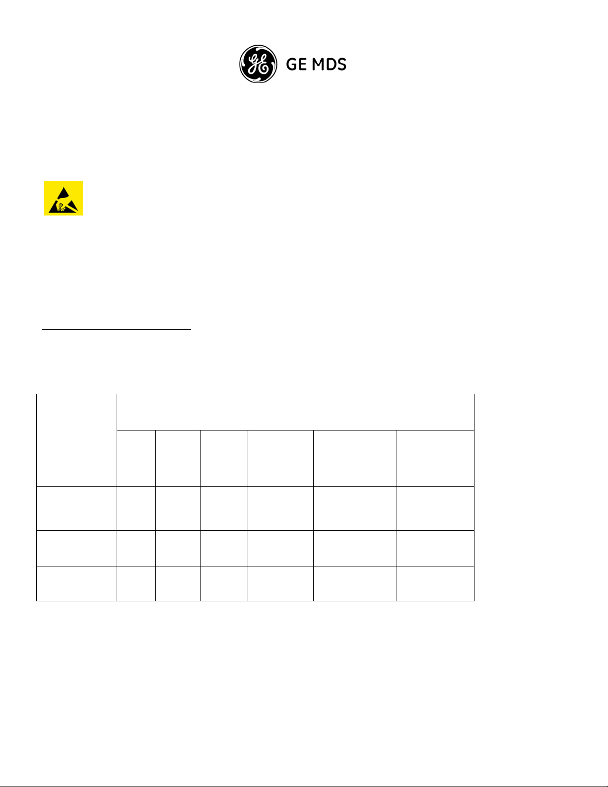
Safety Precautions & Declared Material (continued)
Static electricity may cause bodily harm, as well as harm to electronic components
inside the device.
Anyone responsible for the installation or maintenance of the IDU must use an
ESD Wrist Strap.
ESD protection measures must be observed when touching the IDU.
To prevent damage, before touching components inside the device, all electrostatic
must be discharged from both personnel and tools.
RoHS Compliance Declaration
子信息品有毒有害物申明
Component
/
PCB/Circuit
Modules
Mechanica l Par t s
Cabl es
Electronic Info r mation Pro duct s Decl arati on of Haz ardous /Toxic Substanc es
Hazardous Substance
Lead
(Pb)
Comply Comply Comply Comply Comply Comply
Comply Comply Comply Comply Comply Comply
Comply Comply Comply Comply Comply Comply
Mercury
(Hg)
Cadmium
(Cd)
Hexavalent
Chromium (Cr
VI)
Polybrominated
Biphenyls (PBB)
Polybrominated
Diphenyl Ethers
(PBDE)
Page 6

Page 7

Chapter 1: Installation
General
This guide provides insta llation procedures for the following GE MDS Intrepid-HC HP systems:
GE MDS Intrepid-HC HP 1+0/1+1 configuration
GE MDS Intrepid-HC HP 2+2 XPIC configuration
GE MDS Intrepid-HC HP N+1 configuration
Abou t GE MDS Intrepid-HC HP
The GE MDS Intrepid-HC HP supports multiple capacities, frequencies, modulation sc hemes, and configurations
for various network re quirements. Its RF transceiver units operate in the fr equency range of 6-11 GHz.
GE MDS Intrepid-HC HP capacities can be upgraded from 45 Mbps up to N x 155 Mbps.
For long distance links and bac kbone requirements, GE MDS Intrepid-HC HP offers Space Diversity functionality.
Each transceiver can contains two receivers and one transmitter, which enable built-in diversity capa bility.
Built in Diversity in each transceiver increases the reliability of the link. In a 1+1/2+2 Hot Standby or N+1
configuration w ith Space Diversity, if a hardware failure occurs, the Diversity will not be affected.
GE MDS Intrepid-HC HP is installed in a Split-Mount configura tion, as shown in the following example
illustration.
GE MDS Intrepid-HC HP Installation Guide 1-1
Page 8
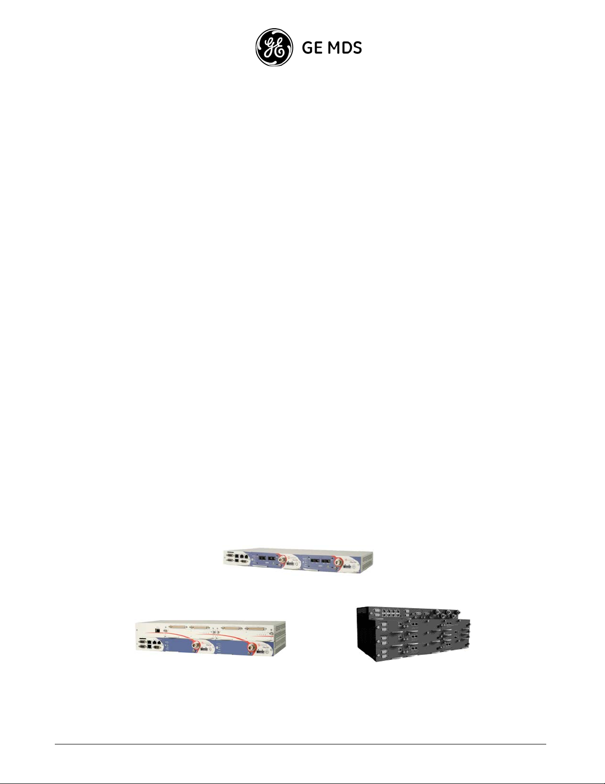
2+0 Confi gurati on
The GE MDS Intrepid-HC HP RFU works together with Intrepid-HC, Intrepid-HC HP/T, and Intrepid-HC 64P,
which are modular network connec tivity IDUs designed to meet growing market demands for increased spectralefficient systems.
GE MDS Intrepid-HC is designed to deliver double the ca pacity using a single 28 MHz wide channel. The system
is easy to install, offers a variety of interface possibilities, and represents a cost-effective alternative to fiber.
GE MDS Intrepid-HC HP/T (all indoor, trunked unit) is a high capacity N+1 trunk radio system that was designed
to support multiple capacitie s, frequencies, modulation schemes, and configurations for various network
requirements.
GE MDS Intrepid-HC 64P is a high capacity PDH radio designed for seamless upgra de from medium to high
capacity, with a built-in Fast Ethernet port and switch.
GE MDS Intrepid-HC HP RFUs together with the different GE MDS IDUs provide a powerful, reliable, a nd
comprehensive solution for a variety of wireless network scenarios and requirements.
GE MDS Intrepid-HC HP RFU
GE M D S Intre pi d -HC I D U
GE MDS Intrepid-HC 64P IDU GE MDS Intrepid-HC HP/T IDU
1-2
GE MDS Intrepid-HC HP Installation Guide
Page 9
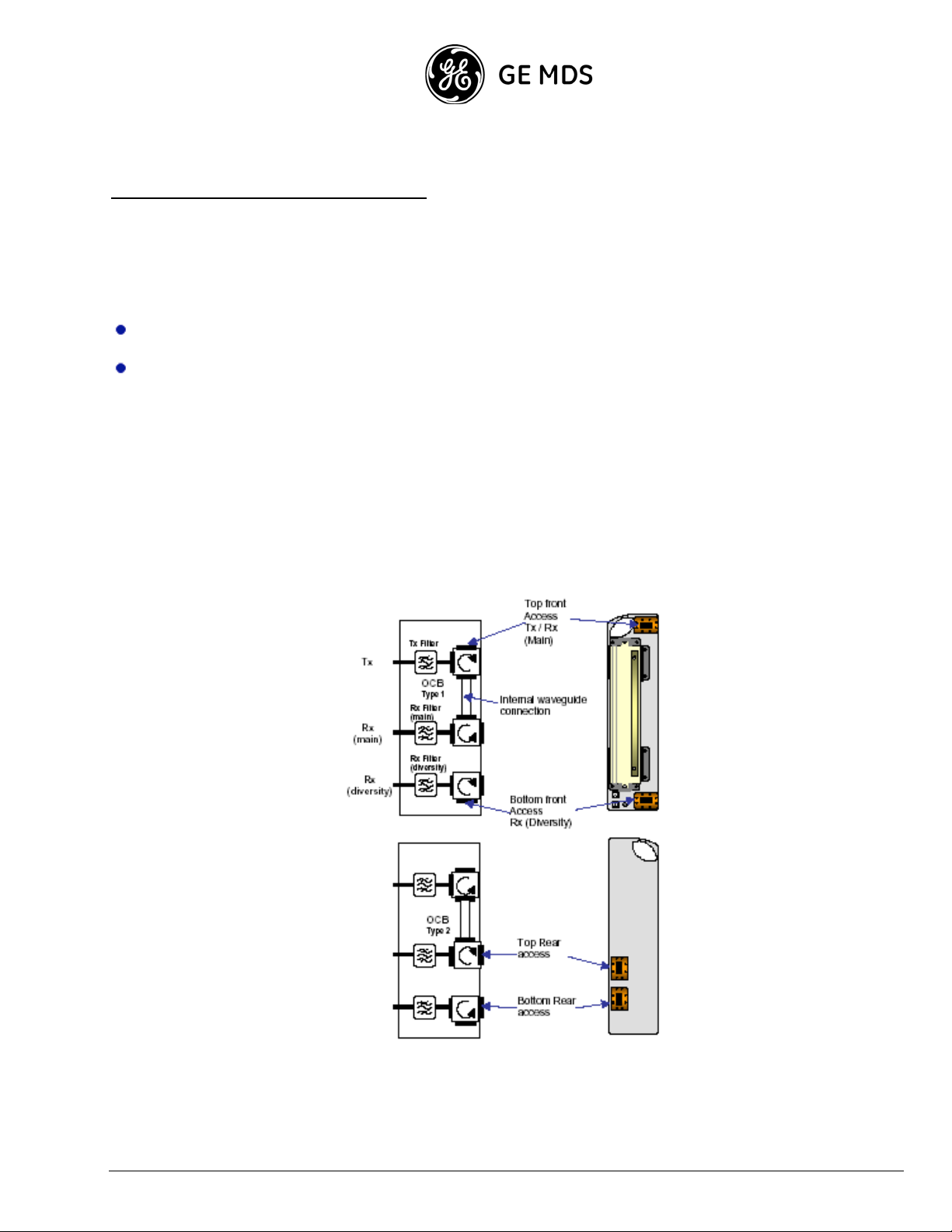
About the GE MDS Intrepid-HC HP OCBs
GE MDS Intrepid-HC HP RFUs and OCBs (Outdoor Circulator Blocks) can be chained in different ways for
different configurations.
Two types of OCBs can be used:
Type1 OCB
Type2 OCB
The main difference between the tw o types are the cir culator directions. Depending on the configur ation, OCB Type
1 or Type 2 are used together with waveguide shorts, waveguide loads, U Bends, C Bends, or couplers.
Each OCB has four waveguide access points: two in the front, and two at the rear. The diversity access point is
optional.
If the system is not configured f or diversity, all the relevant access points on the OCB must be terminated using
waveguide shorts
.
Type 1 OCB
Type 2 OCB
GE MDS Intrepid-HC HP Installation Guide 1-3
Page 10
s
1+0/1+1 Installation
This section describe s the installation procedure for GE MDS Intrepid-HC HP in a 1+0 or 1+1 configuration.
The components involved in this proce dure include the following:
RFU
OCB
Hang e r Ki t
Pole Mount Kit
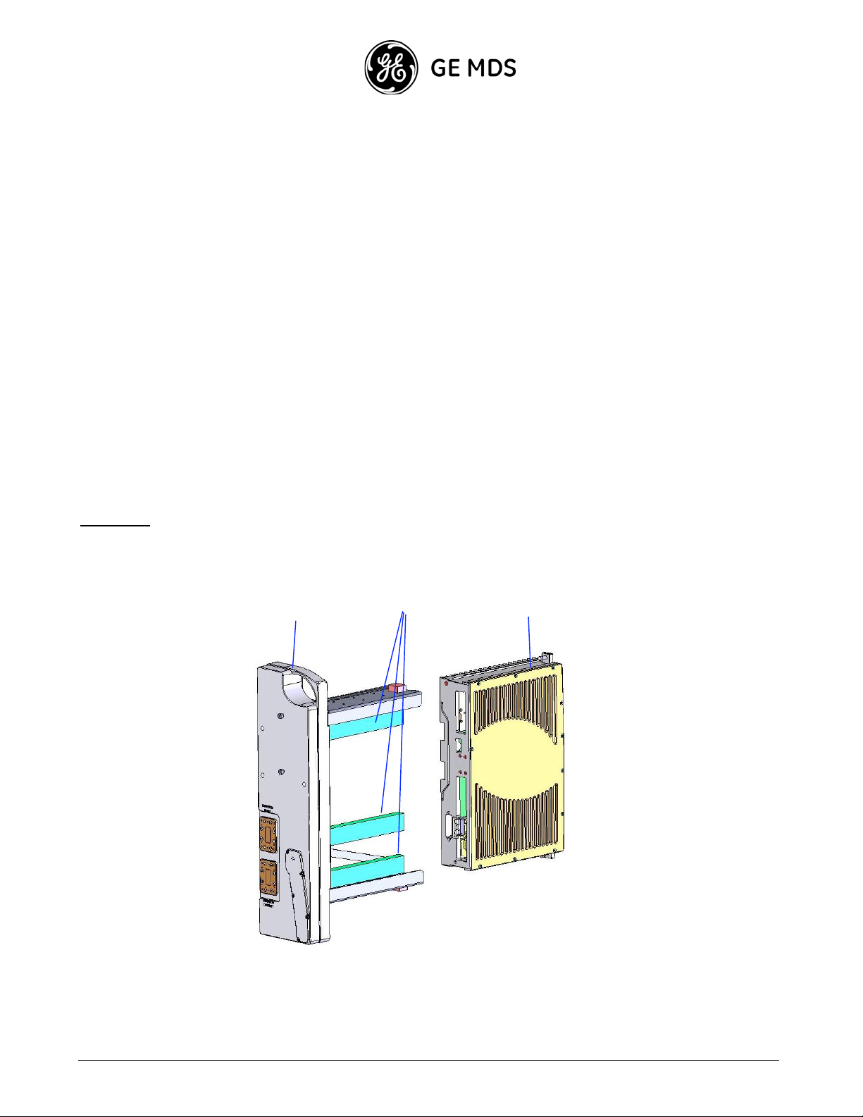
Assembling the RFU and OCB
The RFU is generally assembled in the factor y with the OCB, and de livered as a single unit.
If the RFU is delivered separate ly with the OCB, do the follow ing:
Important:
1. Remove the RFU and the OCB from the box.
The instructions in this guide should be performed indoors.
OCB
Filter
RFU
2. Make sure that the OCB sealing gasket is in place.
1-4
GE MDS Intrepid-HC HP Installation Guide
Page 11
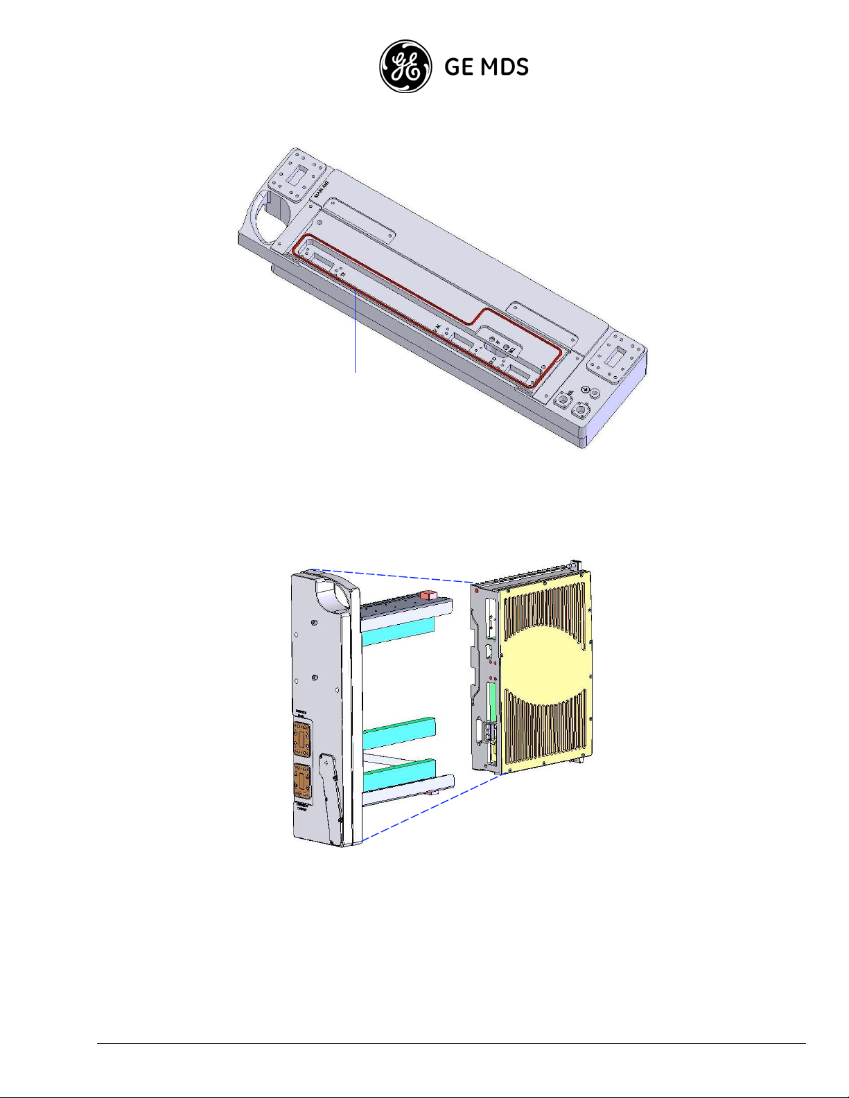
OCB
Sealing
Gasket
3. Gently slide the RFU in the OCB, making sure that the two empty spaces in the RFU correspond to the filte r
positions on the OCB.
4. Tighte n the Allen Head screws to the OCB using an Allen wrench.
GE MDS Intrepid-HC HP Installation Guide 1-5
Page 12
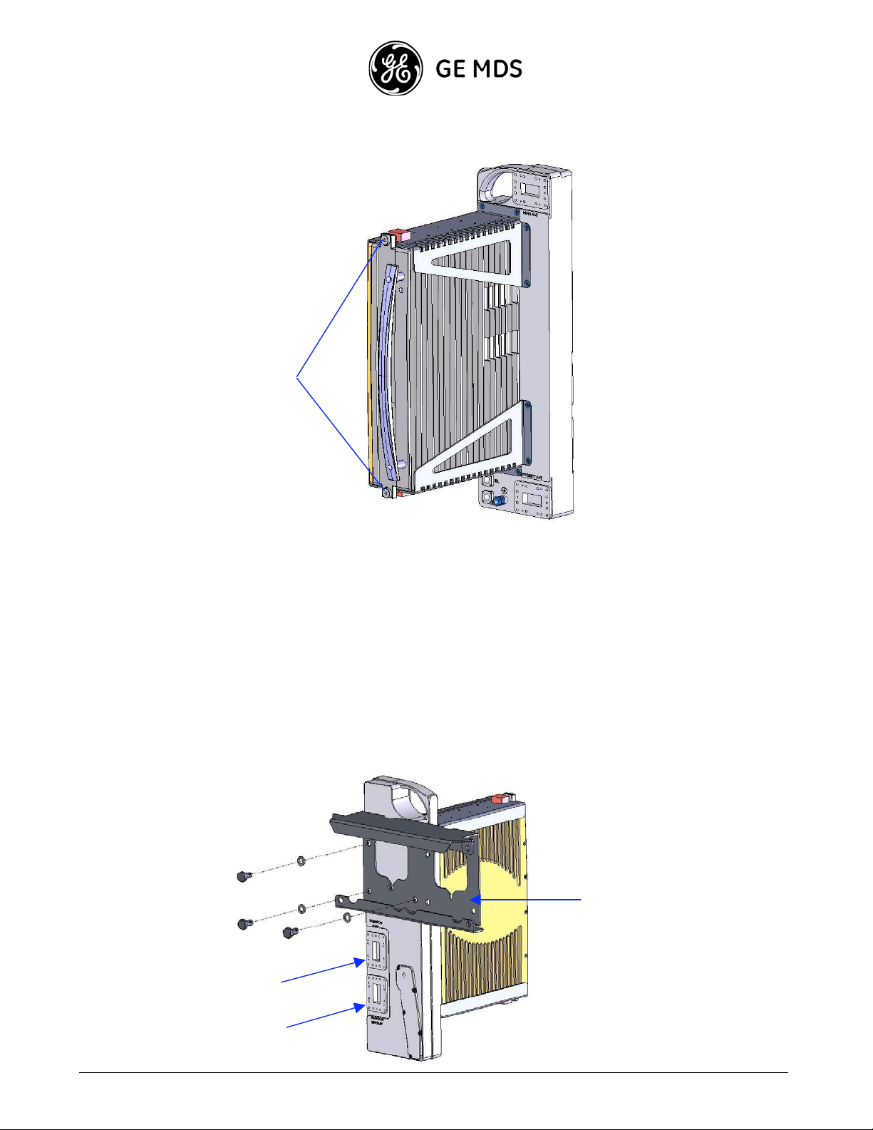
)
Allen
Head
Screws
Assembling the Hanger Kit
The Hanger Kit is used to connect two RFUs and OCBs to the Pole Mount Kit. It consists of a single metal plate.
To assemble the Hanger Kit together with the RFU and OCB:
1. Place the RFU on the floor and hold it upright, as shown in the photo below.
2. Place the Hanger Kit in line with the OCB, as shown in the illustration below , a nd fasten the Kit to the OCB
using 3 large (M-10 type) screws.
Three Screws
1-6
Fas teni ng the
Hanger Kit to
the
OCB
Main
Extension
Diversity
GE MDS Intrepid-HC HP Installation Guide
Hanger Bend
(to place on
the
Pole Kit
Page 13
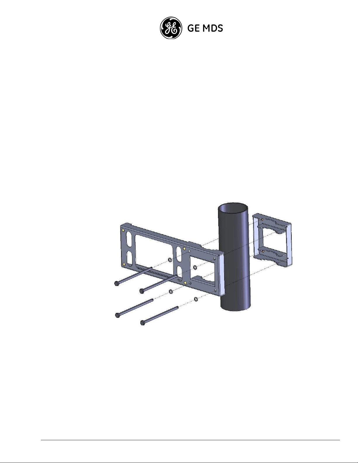
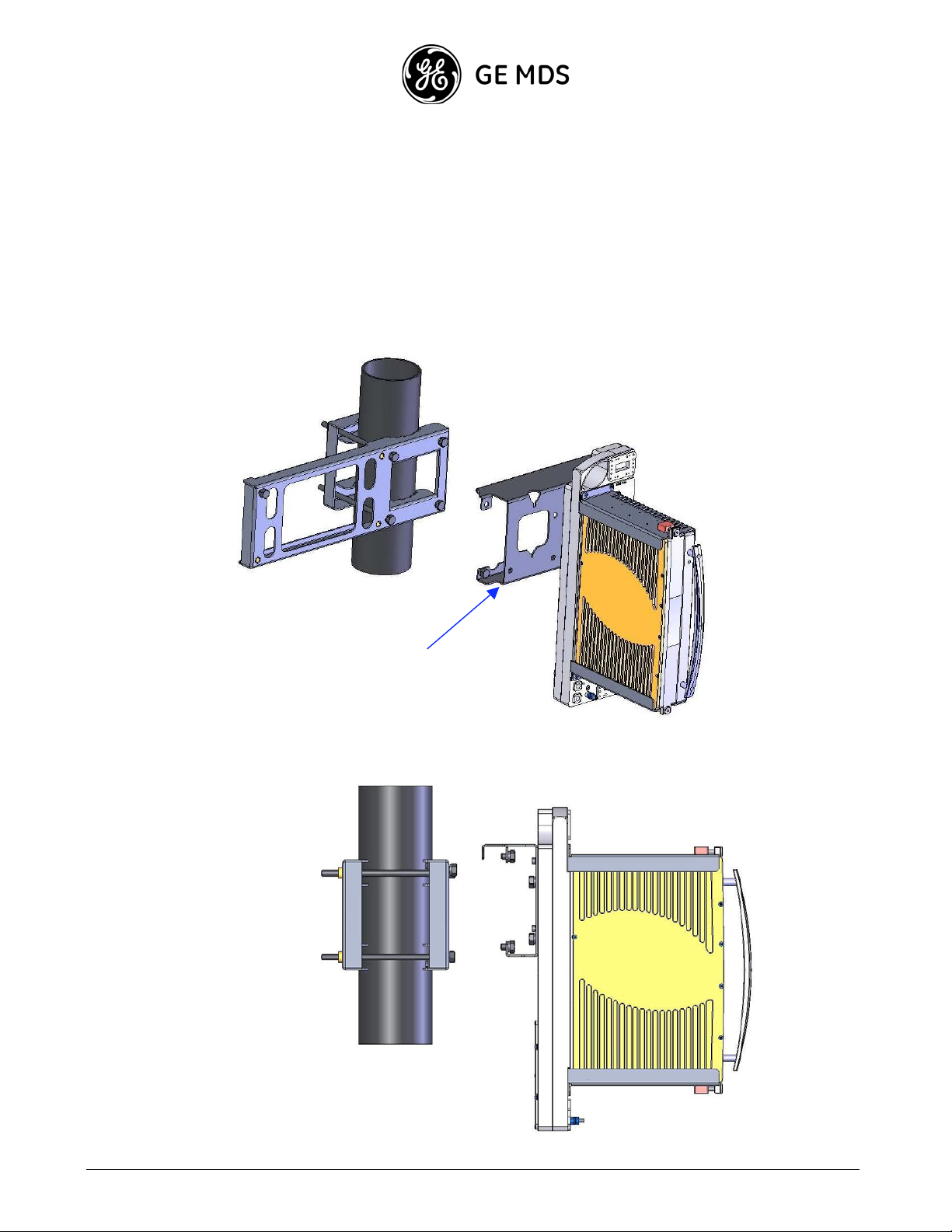
Assembling the Pole Mount Kit
The Pole Mount Kit is used to connect the Hanger Kit (together with the RFU and OCB) to the pole.
The kit consists of a single metal plate with a clamp assem bly.
Important: The diameter of the pole upon whic h the kit is mounted must be between 50 mm (2") and
125 mm (5").
To assemble the Pole Mount Kit on the pole:
1. Open the Pole Mount Kit clamp, and assemble the kit on the pole, as shown in the following illustration.
Four Screws
Fas teni ng the
Pole Mo unt Kit
to the Po l e
2. Fasten the kit to the pole using the 4 screws, as shown in the photo above.
GE MDS Intrepid-HC HP Installation Guide 1-7
Page 14
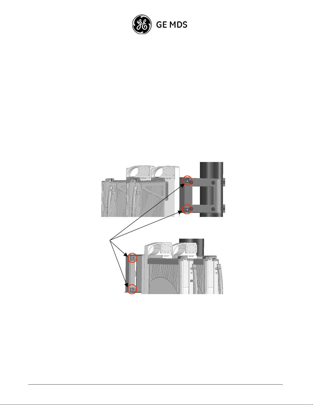
Assembling the Hanger Kit (with RFU and OCB) and Pole Mount Kit
To assemble the Hanger Kit and the Pole Mount Kit:
1. Lift the Hanger Kit with the fastene d RFU and OCB, and hang it, using the Hanger Bend, on the Pole Mount
Kit, as shown in the following illustrations.
Hanger
Bend
Side view
showing how
the Hanger
Kit is hung on
the Pole
Mount Kit.
1-8
GE MDS Intrepid-HC HP Installation Guide
Page 15

Mount Kit.
Side view of
the Hanger
Kit assembled
on the Pole
2. Faste n the Hanger Kit to the Pole Mount Kit using 4 large (M-10 type) screws, as shown in the following
illustration.
Screws
fastening
the Hanger
Kit to the
GE MDS Intrepid-HC HP Installation Guide 1-9
Page 16
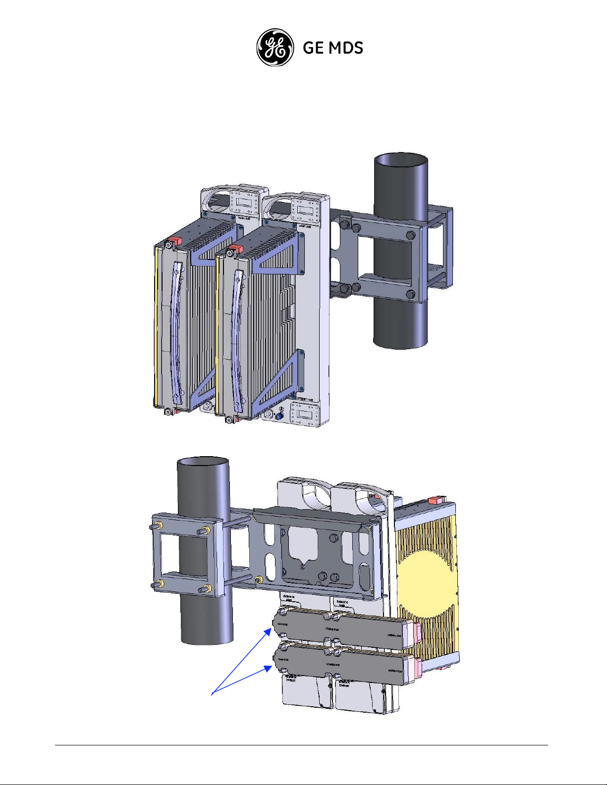
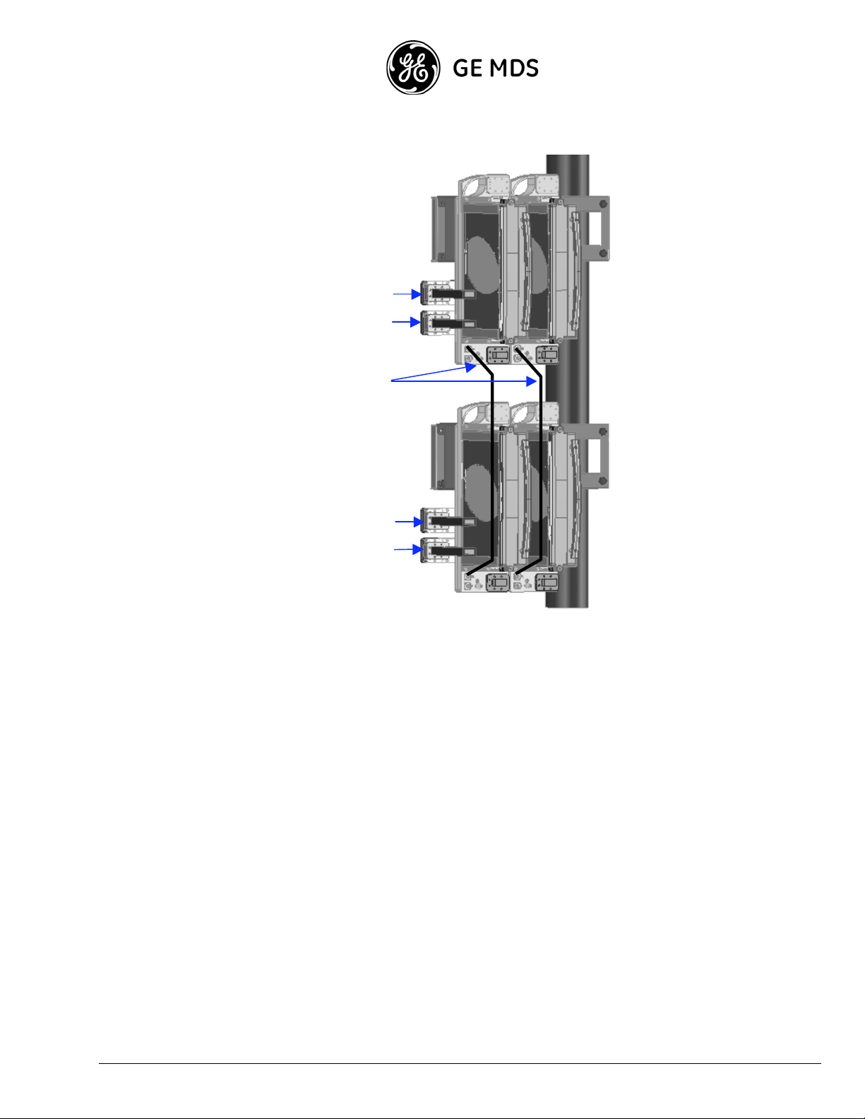
Each Pole Mount Kit can accommodate two RFUs and OCB units, as shown in the following illustration.
Couplers
1-10
GE MDS Intrepid-HC HP Installation Guide
Page 17
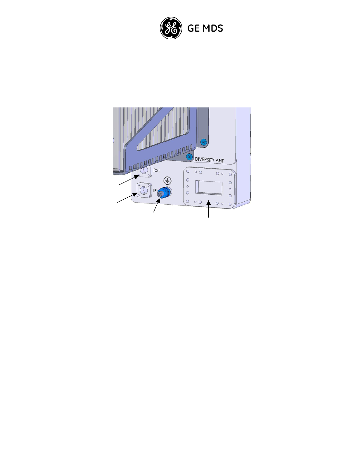
RFU Cable Connections
The RFU cable connectors are located on the bottom of the RFU, as shown in the following photo:
XPIC/RSL
IF
Ground
Waveguide
The connections include the following:
XPIC/RSL For XPIC functionality and radio signa l monitoring.
IF Connects the RFU to the IDU.
Ground Used for electrical gr ound.
Flexible Waveguide Connects the RFU to the antenna.
GE MDS Intrepid-HC HP Installation Guide 1-11
Page 18

2+2 XPIC Installation
This section describe s the installation procedure for GE MDS Intrepid-HC HP in a 2+2 XPIC configuration.
Flexible Waveguide
Connection to Main
Horizontal and
Vertical Antenna
Ports
Elliptical Waveguide
/ Waveguide-toCoax Connection to
Diversity Horizontal
and Vertical
Antenna Ports
1-12
GE MDS Intrepid-HC HP Installation Guide
Page 19
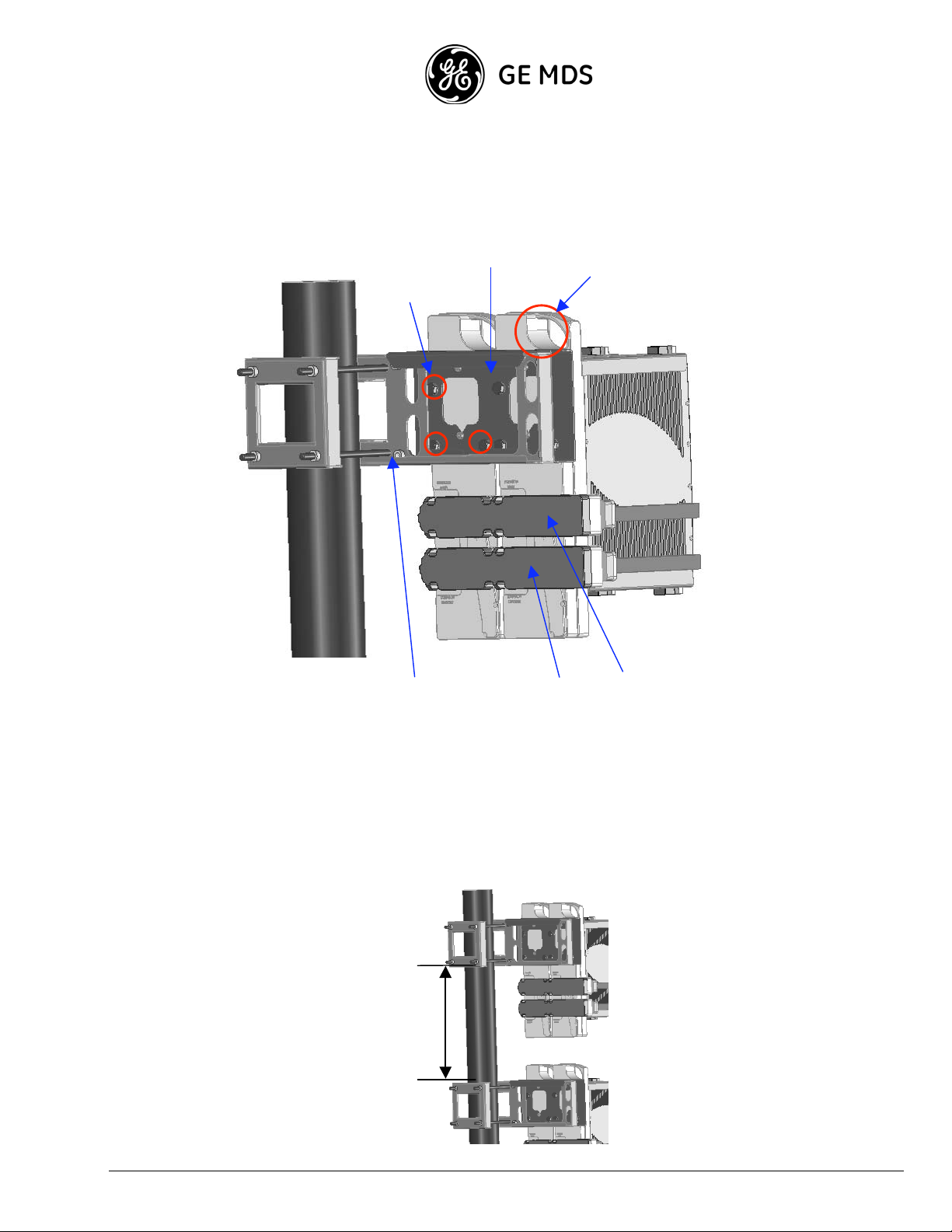
Installation Components
M10 Scre ws
Fastening
the OCB to
the Hanging
Bracket
Hanging
Bracket
Lifting
Handle
Pole Mount
Kit with Cl amp
Bracket
Diversity
Coupler
Main
Coupler
Installation Procedure
1. Connect both pole mount kits to the pole.
If the RFUs are to be assembled one above the other, there should be a minimum distanc e of 40 cm between
the two pole mount kits, as shown in the following illustration.
40 cm
GE MDS Intrepid-HC HP Installation Guide 1-13
Page 20
Important: The diameter of the pole upon which the kit is mounted must be between 50 mm (2") and
125 mm (5").
2. Connect shorts and 50 ohm terminations on all OCBs (shorts on main antenna ports, 50 ohm terminations on
diversity antenna por ts).
3. Assemble both couplers on the OCBs.
4. Attach the hanging bracke t to the OCBs and tighten the screw s that fasten the OCB to the hanging-bracket.
5. Gently lift the assembled unit to the pole using the lifting handle.
6. Place the assembled units on the pole mount clamp bracket and fasten the M10 screws, as shown in the
following illustration.
M10 Scre ws used
to Fasten the Units
to the Pole M ount
Clamp
7. Connect the XPIC cables between the units, as shown in the following illustration.
1-14
GE MDS Intrepid-HC HP Installation Guide
Page 21
Main Antenna H Pole Port
Diver s i ty Antenn a H Po l e Port
XPIC Cables
Main Antenna V Pole Port
Diver s i ty Antenn a V Pole Port
8. Connect the flexible wa veguides to the antennas, as shown in the illustration above (V and H poles are
selected as requir ed - in the illustration above they are selected arbitrar ily).
GE MDS Intrepid-HC HP Installation Guide 1-15
Page 22
g
(
)
N+1 Split Mount Installation
This section describe s the installation procedure for GE MDS Intrepid-HC HP in an N+1 split mount configuration,
where N is less than or equal to 5.
A split mount N+1 configuration is achieved using Type-1 and Type-2 OCBs alternatively.
Two Type 1 a nd Type 2 OCBs are interconnected via U bends at the rear extension ports. The third OCB is chained to
the second OC B through the main and diversity ports, using a flexible waveguide.
Each OCB is conne cted to the relevant IF ca ble from the Intrepid-HC HP /T Baseband Indoor.
The following example shows a 4+1 space diversity dual pole configuration.
Flexible
Wave
uide
To Main V
Antenna
Flexible
Waveguide
Termination
U Bend
To Diversity V
Antenna
To Main H
Antenna
U Bend
To Diversity H
Antenna
4+1 SD Dual Pole
Split Mount
(OCB Front View)
1-16
GE MDS Intrepid-HC HP Installation Guide
4+1 SD Dual Pole
Split Mount
OCB Rear View
Page 23
Note: When installing an N+1 configuration, a ssemble the OCBs in an inverted order, to maintain the same
branching loss betwee n the carriers, as shown in the following illustration.
Site A
C1
C2
C3
Site B
C3
C2
C1
GE MDS Intrepid-HC HP Installation Guide 1-17
Page 24

Installation Configuration Illustrations
This section provide s illustrations of different GE MDS Intrepid-HC HP installation conf igurations.
Note that in this section, the following abbreviations are used:
HSB - Hot Standby
FD - Frequency Diversity
SD - Space Diversity
DP - Dual Pole
MP - Main Path
SP - Secondary Path
MA - Main Antenna
DA - Diversity Antenna
N/A - Not Applicable
WG - Waveguide
X/Y dB: X refers to 6-8 GHz, Y refers to 11 GHz
1-18
GE MDS Intrepid-HC HP Installation Guide
Page 25
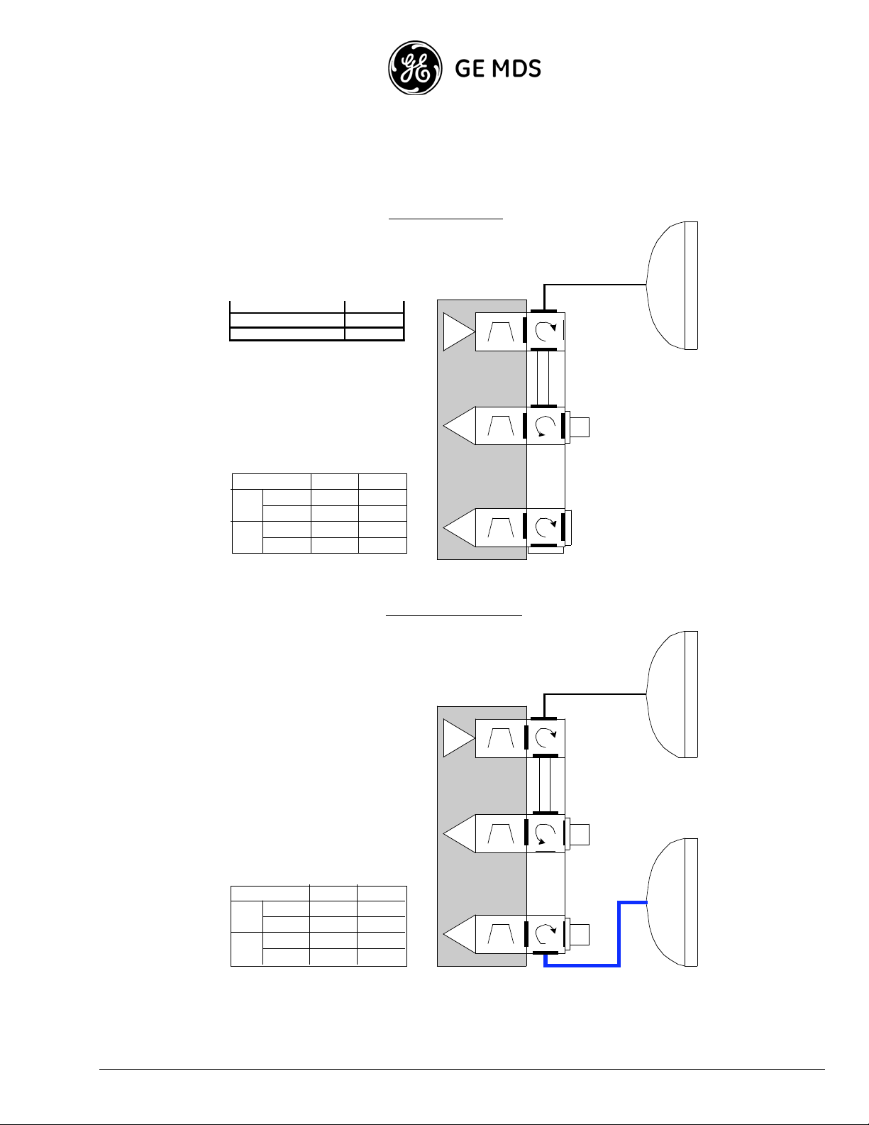
1+0 & 1+0 Space Diversity
SP Ant
1
ID M-155 1
enna
IDC + Ch as s i s 1
1+0 Configuration
TX
RFU
Flexible WG
TX f1
TX Filter
1+0
M.A
M.P
D.A
M.A
S.P
D.A
1+0 SD
M.A
M.P
D.A
M.A
S.P
D.A
* Coax Cabl e 3.5/ 5dB
B.L W.G
0dB 0.5dB
N/A N/A
N/A
N/A
N/A
N/A
B.L W.G
N/A
N/A
0.5dB
1.5/2.5dB*
N/A
N/A
0dB
0dB
RX f1
RX M
RX Fi lte r
RX f1
RX D
RX Fi lte r
1+0 SD Configuration
TX
TX f1
TX Filter
RFU
RX M
RX f1
RX Fi lte r
RX f1
RX D
RX Fi lte r
OCB
typ e 1
OCB
typ e 1
50
ohm
Flexible WG
50
ohm
50
ohm
Eliptical W G
or Coax Cable
GE MDS Intrepid-HC HP Installation Guide 1-19
Page 26
Pole Mount 1
1+1 Hot Standby & 1+1 Hot Standby Space Diversity
1+1 HSB Configuration
50ohm Termination 2
Short 4
Coupler Ty pe 1 1
Flex WG 1. 2m 1
SP Antenna 1
IDC + Chassis 1
IDM-155 2
Protection Kit 1
M.A
D.A
M.A
D.A
B.L W.G
1.6/1.8dB 0.5dB
N/A
7/7.4dB
N/A
1+1 HSB
M.P
S.P
N/A
0.5dB
N/A
50
oh
m
TX
TX
f1
TX Filter
RFU
RX f1
RX M
RX Fi lte r
OCB
type
2
RX f1
RX D
RX Fi lte r
TX
TX Filter
RFU
RX M
RX Fi lte r
RX D
RX Fi lte r
RX f1
RX f1
50
oh
m
TX
f1
F le xible WG
OCB
type
2
1+1 SD Configuration
50
oh
m
TX
TX f1
TX Filter
RFU
TX
TX Filter
RFU
50
oh
m
TX
f1
F le xible WG
1-20
GE MDS Intrepid-HC HP Installation Guide
1+1 SD
M.A
M.P
D.A
M.A
S.P
D.A
* Coax Cabl e 3.5/ 5dB
B.L W.G
1.6/1.8dB
1.6/1.8dB
7/7.4dB
0.5dB
1.5/2.5dB*
0.5dB
1.6/1.8dB 1.5/2.5dB*
RX f1
RX M
RX Fi lte r
OCB
typ e 2
RX f1
RX D
RX Fi lte r
50
oh
m
RX f1
RX M
RX Fi lte r
OCB
typ e 2
RX f1
RX D
RX Fi lte r
50
oh
m
Eliptical W G
or Coax Cable
Page 27
1+1 Frequency Diversity & 1+1 Frequency Diversity + Space Diversity
1+1 FD Configuration
50ohm Termination 1
Short 4
U Bend WG Type 1 1
Flex WG 1.2m 1
SP Antenna 1
IDC + Ch ass is 1
IDM-155 2
Protection Kit 1
M.P
S.P
1+0 FD
M.A
D.A
M.A
D.A
B.L W.G
0.25dB
N/A
N/A
N/A
0.5dB
N/A
N/A
N/A
50
ohm
TX
TX f3
TX Filter
RFU
RX f3
RX M
RX Fi lte r
OCB
typ e 2
RX f3
RX D
RX Fi lte r
1+1 FD/SD Configurati on
Flexible WG
TX
TX f1
TX Filter
RFU
RX f1
RX M
RX Fi lte r
OCB
typ e 1
RX f1
RX D
RX Fi lte r
Flexible WG
50
ohm
TX
TX f3
TX Filter
8GHz RFU
RX f3
RX M
RX Fi lte r
OCB
typ e 2
1+0 SD
M.A
M.P
D.A
M.A
S.P
D.A
B.L W.G
1.5/2.5dB*
0.25dB
N/A
N/A
0.5dB0.25dB
N/A
N/A
RX f3
RX D
RX Fi lte r
U bends
50
ohm
* Coax Cabl e 3.5/ 5dB
TX
TX f1
TX Filter
8GHz RFU
RX f1
RX M
RX Fi lte r
OCB
typ e 1
RX f1
RX D
WG
RX Fi lte r
Eliptical W G or
Coax Cable
GE MDS Intrepid-HC HP Installation Guide 1-21
Page 28
1+1 Space Diversity BBS
1 +1 S D BBS Configura tion
TX
TX f1
TX Filter
RFU
Flexible WG
Main
antenna
1+0 SD BBS
M.P
S.P
M.A
D.A
M.A
D.A
B.L W.G
0dB 0 .5 dB
0dB 0 .5 dB
N/A
N/A
N/A
N/A
RX M
RX D
RX M
RX D
RX f1
RX F i lte r
OCB
typ e 1
RX f1
RX F i lte r
ohm
50
Flexible WG
TX
TX f1
TX Filter
Diversity
RFU
RX f1
RX F i lte r
RX f1
RX F i lte r
OCB
typ e 1
ohm
50
antenna
1-22
GE MDS Intrepid-HC HP Installation Guide
Page 29
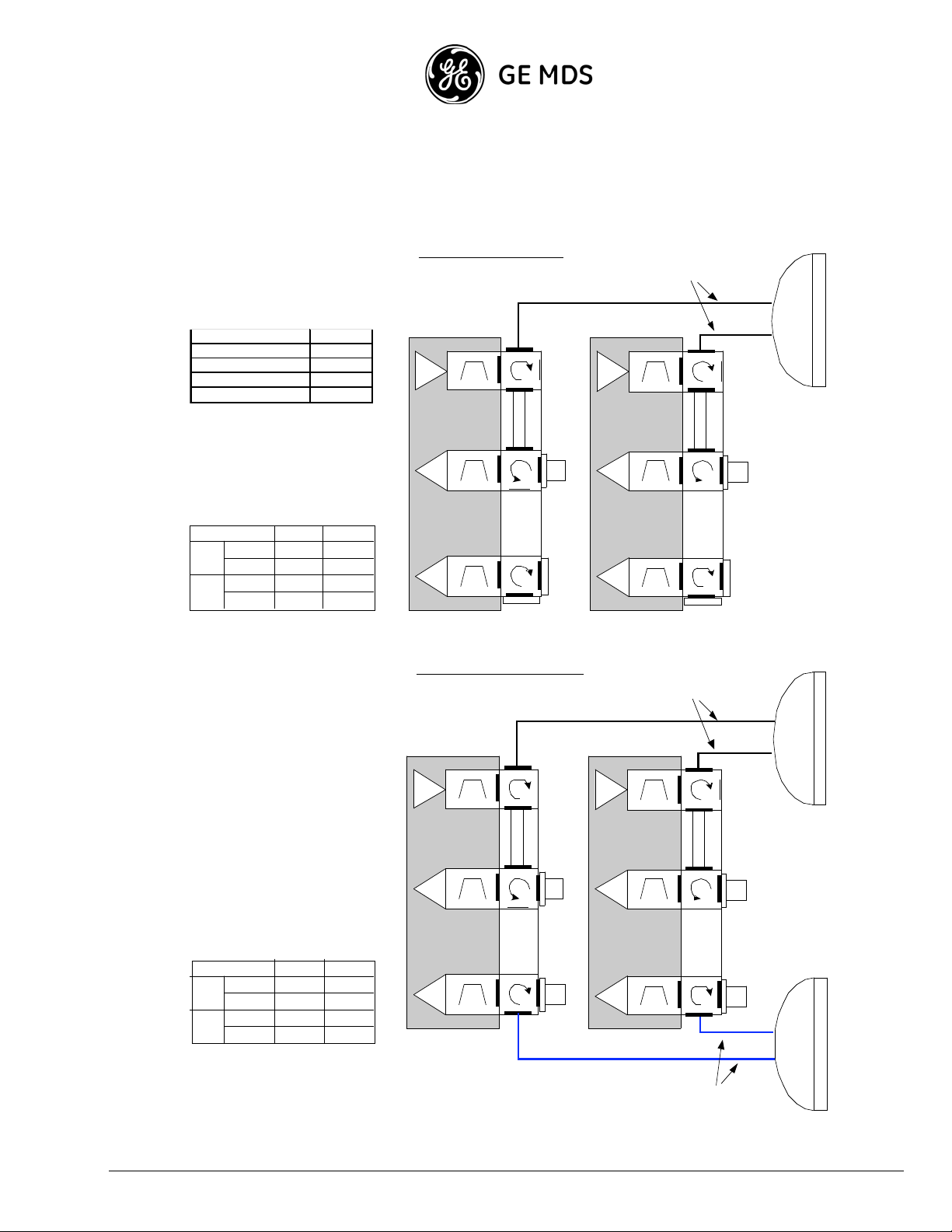
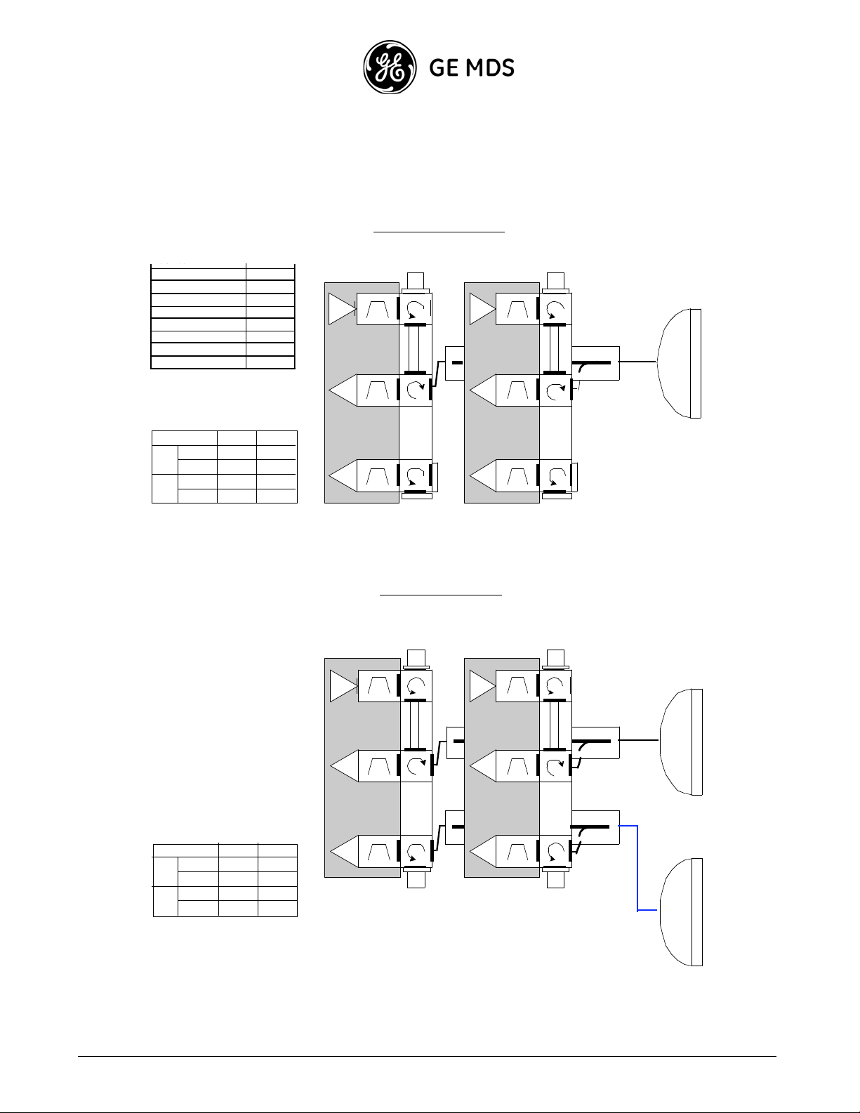
2+0 Dual Pole & 2+0 Space Diversity Dual Pole
2+0 DP Configura tion
Flex WG 1.2m 2
DP Antenna 1
XPIC cable 3m long 1
IDC + Ch ass is 1
IDM-155 2
TX
TX f1
TX Filter
RFU
Flexible WG
TX
TX f1
TX Filter
RFU
2+0 DPA
M.A
M.P
D.A
M.A
S.P
D.A
2+0 SD DP A
M.A
M.P
D.A
M.A
S.P
D.A
* Coax Cabl e 3.5/ 5dB
B.L W.G
0dB 0.5 dB
N/A
N/A
N/A
N/A
N/A
N/A
B.L W.G
N/A
N/A
0.5dB
1.5/2.5dB*
N/A
N/A
0.B
0dB
OCB
type
50
ohm
1
RX M
RX f1
RX Fi lte r
RX f1
RX D
RX Fi lte r
2+0 S D DP Configura tion
TX
TX f1
TX Filter
RFU
OCB
typ e 1
50
ohm
50
ohm
RX M
RX f1
RX Fi lte r
RX f1
RX D
RX Fi lte r
OCB
type
50
ohm
1
RX f1
RX M
RX Fi lte r
RX f1
RX D
RX Fi lte r
Flexible WG
TX
TX f1
TX Filter
RFU
OCB
typ e 1
50
ohm
50
ohm
RX f1
RX M
RX Fi lte r
RX f1
RX D
RX Fi lte r
Eliptical W G or
Coax Cable
GE MDS Intrepid-HC HP Installation Guide 1-23
Page 30
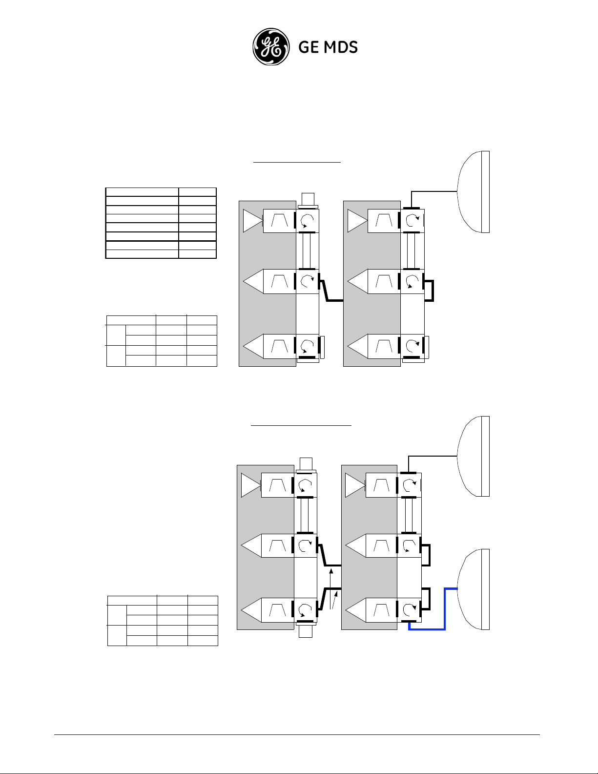
2+0 Single Pole & 2+0 Space Diversity Single Pole
2+0 S P Configuration
Pole Mount 1
50ohm Termination 1
Short 4
U Bend W G Type 1 1
Flex W G 1.2m 1
SP Antenna 1
IDC + Ch ass is 1
IDM-155 2
2+0 SPA
M.P
S.P
M.A
D.A
M.A
D.A
B.L W.G
0.25dB 0.5dB
N/A
N/A
N/A
N/A
N/A
N/A
50
ohm
TX f2
TX
TX Filter
RFU
RX f2
RX M
RX Fi lte r
OCB
typ e 2
RX f2
RX D
RX Fi lte r
2+0 S D S P Configuration
50
ohm
Flexible WG
TX f1
TX
TX Filter
RFU
RX f1
RX M
RX Fi lte r
OCB
typ e 1
RX f1
RX D
RX Fi lte r
Flexible WG
2+0 SD SPA
M.P
S.P
M.A
D.A
M.A
D.A
B.L W.G
0.25dB
1.5/2.5dB*
0.25dB
N/A
N/A
0.5dB
N/A
N/A
TX
RX M
RX D
8GHz RFU
TX f1'
TX Filter
RX f1
RX Fi lte r
RX f1
RX Fi lte r
OCB
typ e 2
ohm
U bends
WG
50
TX
RX M
RX D
8GHz RFU
TX f0'
TX Filter
RX f0
RX Fi lte r
RX f0
RX Fi lte r
OCB
typ e 1
Eliptical W G or
Coax Cable
* Coax Cabl e 3.5/ 5dB
1-24
GE MDS Intrepid-HC HP Installation Guide
Page 31

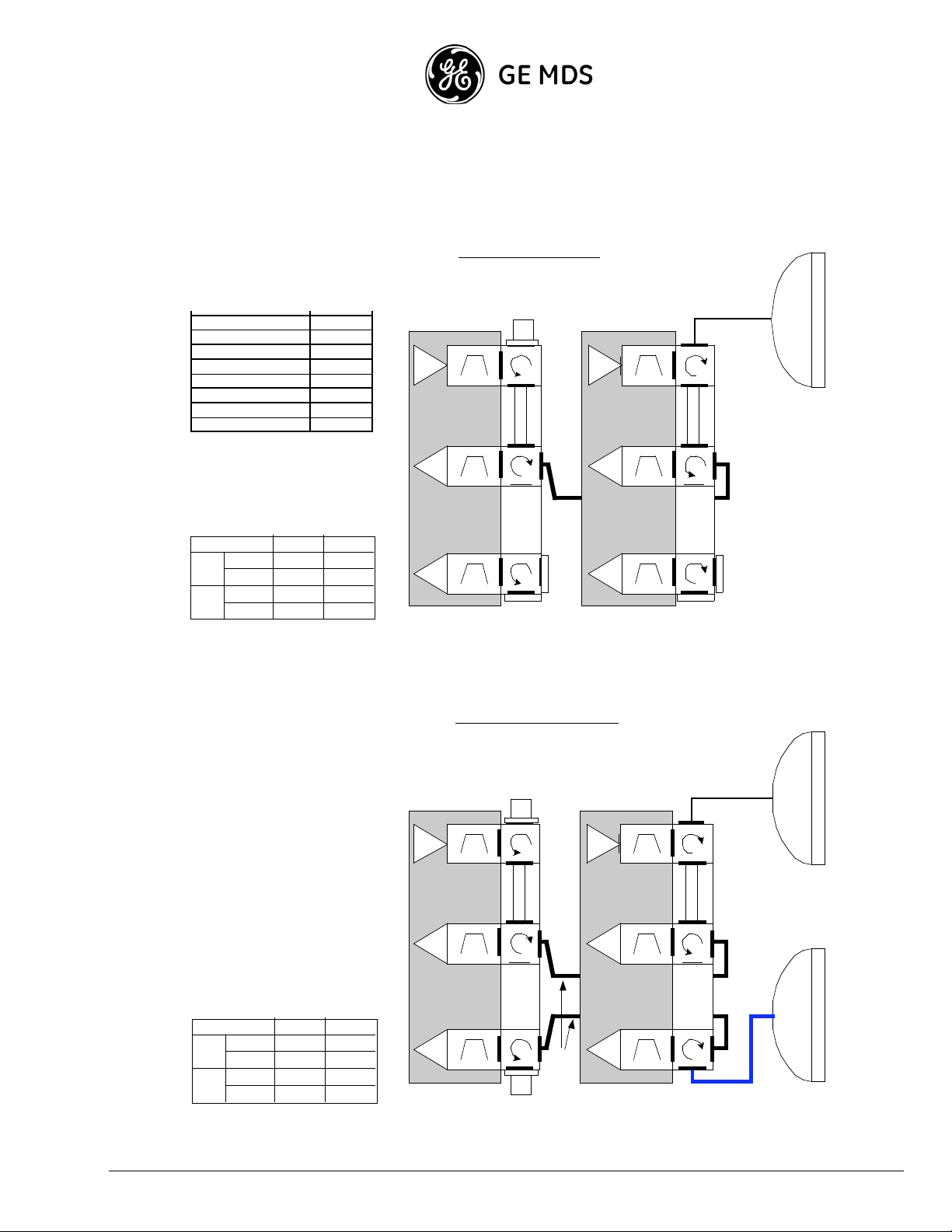
2+2 Hot Standby Dual Pole
2 +2 HSB DP Configur ati o n
RX M
RX D
50
ohm
TX f1
TX
TX Filter
TX f1
TX
TX Filter
50
ohm
Flexible WG
RFU
RX f1
RX Fi lte r
OCB
typ e 2
RX f1
RX Fi lte r
50
ohm
TX f1'
TX
TX Filter
RFU
RX M
RX D
RFU
RX f1
RX Fi lte r
OCB
typ e 2
RX f1
RX Fi lte r
50
ohm
TX f1'
TX
TX Filter
RFU
RX M
RX D
RX f1'
RX Fi lte r
RX f1'
RX Fi lte r
OCB
typ e 2
2+2 HSB DPA
M.A
M.P
D.A
M.A
S.P
D.A
RX f1'
RX M
RX Fi lte r
RX f1'
RX D
RX Fi lte r
B.L W.G
1.6/1.8dB 0.5dB
N/A
7/7.4dB
N/A
typ e 2
N/A
0.5dB
N/A
OCB
GE MDS Intrepid-HC HP Installation Guide 1-25
Page 32

C
21
2+2 Hot Standby Single Pole
2+2 HSB SP Configura tion
50
ohm
Flexible WG
RX M
RX D
TX
TX f2
TX Filter
RFU
TX
TX f1
TX Filter
RFU
Flexible WG
RX f2
RX Fi lt e r
RX f2
RX Fi lt e r
OCB
typ e 2
ohm
50
RX M
RX D
RX f1
RX Fi lt e r
OCB
typ e 1
RX f1
RX Fi lt e r
oupler Type
Flex W G 1.2m 2
TX
TX f2
TX
TX f1
SP Ant e nn a 1
IDC + Ch as s i s 2
TX Filter
RFU
RFU
TX Filter
IDM-155 4
Protection Kit 2
RX M
RX D
1-26
GE MDS Intrepid-HC HP Installation Guide
RX f2
RX Fi lt e r
RX f2
RX Fi lt e r
OCB
typ e 2
RX M
RX D
RX f1
RX Fi lt e r
RX f1
RX Fi lt e r
OCB
typ e 1
2+2 HSB SPA
M.A
M.P
D.A
M.A
S.P
D.A
B.L W.G
1.9/2.1dB
N/A
7.3/7.7dB
N/A
0.5dB
N/A
1dB
N/A
Page 33

2+2 Space Diversity Dual Pole
2+2 S D DP Configura tion
50
ohm
TX
TX f1
TX Filter
RFU
RX M
RX f1
RX Fi lte r
OCB
typ e 2
RX f1
RX D
RX Fi lte r
TX
TX f1
TX Filter
50
ohm
50
ohm
RFU
TX
TX f1
TX Filter
RFU
RX M
RX f1
RX Fi lte r
RX f1
RX D
RX Fi lte r
TX
TX f1
TX Filter
RFU
ohm
OCB
typ e 2
ohm
ohm
50
Flexible WG
50
50
RX M
RX D
RX f1
RX Fi lte r
RX f1
RX Fi lte r
2+2 SD DP A
M.P
S.P
typ e 2
M.A
D.A
M.A
D.A
OCB
50
ohm
B.L W .G
1.6/1.8dB
1.6/1.8dB
7/7.4dB 0.5dB
7/7.4dB 1.5/2.5dB*
0.5dB
1.5/2.5dB*
RX f1
RX M
RX Fi lte r
OCB
typ e 2
RX f1
RX D
RX Fi lte r
50
ohm
Eliptical W G or
Coax Cable
* Coax Cabl e 3.5/ 5dB
GE MDS Intrepid-HC HP Installation Guide 1-27
Page 34

2+2 Space Diversity Single Pole
50
ohm
2+2 S D S P Configurati on
Flexible WG
TX
TX f2
TX Filter
RFU
RX f2
RX M
RX Fi lte r
OCB
typ e 2
RX f2
RX D
RX Fi lte r
TX
TX f2
TX Filter
RFU
RX f2
RX M
RX Fi lte r
OCB
typ e 2
50
ohm
50
ohm
TX
TX f1
TX Filter
RFU
RX f1
RX M
RX Fi lte r
OCB
typ e 1
RX f1
RX D
RX Fi lte r
TX
TX f1
TX Filter
RFU
RX f1
RX M
RX Fi lte r
OCB
typ e 1
Flexible WG
Flexible WG
Eliptical W G or
Coax Cable
RX f2
RX D
RX Fi lte r
50
ohm
2+2 SD SPA
M.P
S.P
M.A
D.A
M.A
D.A
B.L W.G
1.9/2.1dB
1.9/2.1dB 1.5/2.5dB*
7.3/7.7dB
7.3/7.7dB 2/3dB**
RX f1
RX D
RX Fi lte r
0.5dB
1dB
* Coax Cabl e 3.5/ 5dB
** Coax Cabl e 4/5. 5dB
1-28
GE MDS Intrepid-HC HP Installation Guide
Page 35

2+2 Frequency Diversity Single Pole
2+2 FD S P Configur ation
Flexible WG
TX
RFU
RX M
RX D
Flexible WG
TX
RFU
TX
TX Filter
RX
RX Fi lte r
RX
RX Fi lte r
TX
TX Filter
TX
f3
TX
f1
TX Filter
RFU
RX
f3
OCB
typ e 2
f3
50
oh
m
f4
RX M
RX D
f1
RX Fi lte r
OCB
typ e 1
RX
f1
RX Fi lte r
TX
TX
f2
TX Filter
RFU
RX M
RX D
RX
RX Fi lte r
RX
RX Fi lte r
f2
OCB
typ e 1
f2
2+2 FD SP A
M.P
S.P
M.A
D.A
M.A
D.A
RX M
RX D
RX
f4
RX Fi lte r
OCB
typ e 2
RX
f4
RX Fi lte r
B.L W.G
0.75dB
N/A
N/A
N/A
1dB
N/A
N/A
N/A
GE MDS Intrepid-HC HP Installation Guide 1-29
Page 36

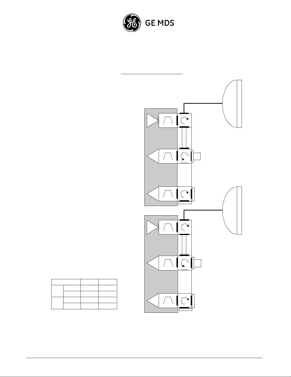
2+2 Hot Standby Frequency Diversity Dual Pole
2+2 HSB FD DP Configura tion
m
50
oh
RX M
RX D
TX
TX f3
TX Filter
RFU
RX f3
RX Fi lt e r
OCB
type
2
RX f3
RX Fi lt e r
RX M
RX D
TX
TX f1
TX Filter
RFU
RX f1
RX Fi lt e r
OCB
type
1
RX f1
RX Fi lt e r
Flexible WG
m
50
oh
TX
TX
f3'
TX Filter
RFU
TX
TX
f1'
TX Filter
RFU
RX M
RX D
2+2 FD DPA
M.P
S.P
M.A
D.A
M.A
D.A
RX f3'
RX Fi lt e r
RX f3'
RX Fi lt e r
OCB
type
2
B.L W.G
0.25dB 0.5dB
N/A
N/A
N/A
N/A
N/A
N/A
RX M
RX D
RX f1'
RX Fi lt e r
OCB
type
1
RX f1'
RX Fi lt e r
1-30
GE MDS Intrepid-HC HP Installation Guide
Page 37

2+2 Frequency Diversity / Space Diversity Dual Pole
2+ 2 S D/FD DP Configuration
50
ohm
Flexible WG
TX f3
TX
TX Filter
RFU
RX M
RX f3
RX Fi lte r
OCB
typ e 2
RX f3
RX D
ohm
RX Fi lte r
TX
TX f3'
TX Filter
RFU
50
50
ohm
TX f1
TX
TX Filter
RFU
RX M
RX f1
RX Fi lte r
OCB
typ e 1
RX f1
RX D
RX Fi lte r
TX
TX f1'
TX Filter
RFU
Flexible WG
Eliptical WG or
Coax Cable
RX M
RX f3'
RX Fi lte r
RX f3'
RX D
RX Fi lte r
3+3 SD DP A
M.A
M.P
D.A
M.A
S.P
D.A
* Coax Cabl e 3.5/ 5dB
OCB
typ e 2
ohm
50
B.L W.G
0.25dB
1.5/2.5dB*
0.25dB
N/A
N/A
0.5dB
N/A
N/A
RX M
RX f1'
RX Fi lte r
OCB
typ e 1
RX f1'
RX D
RX Fi lte r
Eliptical W G or
Coax Cable
GE MDS Intrepid-HC HP Installation Guide 1-31
Page 38

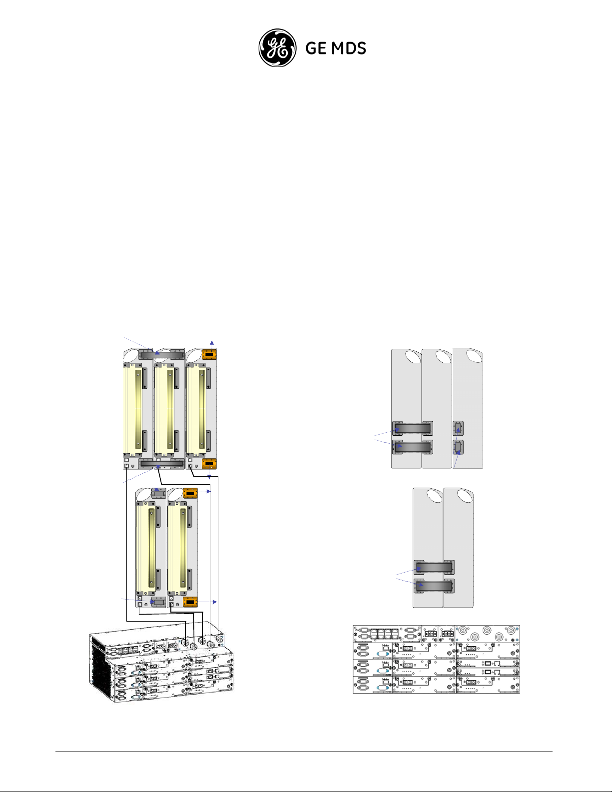
N+1 Systems
4+1 FD DP Configuration
U bends W G
TX f5
TX
TX Filter
RFU
OCB
typ e 1
50
oh
m
RX f5
RX M
RX Fi lte r
RX f5
RX D
RX Fi lte r
TX f3
TX
TX Filter
RFU
RX f3
RX M
RX Fi lte r
OCB
type
2
RX f3
RX D
RX Fi lte r
TX f1
TX
TX Filter
Flexible WG
RFU
RX f1
RX M
RX Fi lte r
OCB
type
1
RX f1
RX D
RX Fi lte r
U bends W G
TX f3'
TX
TX Filter
RFU
RX f3'
RX M
RX Fi lte r
OCB
type
2
TX
TX
f1'
TX Filter
RFU
RX f1'
RX M
RX Fi lte r
OCB
type
1
RX f3'
RX D
RX Fi lte r
N MS & WAYSID E POWER
IDC
IDC
IDC
STM-1
STM-1
STM-1
IDM
IDM
RX f1'
RX D
RX Fi lte r
IF
IF
IDM
STM-1
Switch card (XC)
STM-1
IF
IF
IF
IDM
IDM
1-32
GE MDS Intrepid-HC HP Installation Guide
Page 39

5+1 FD DP Configuration
U bends W G
TX f5
TX
TX Filter
RFU
OCB
typ e 1
50
oh
m
RX f5
RX M
RX Fi lte r
RX f5
RX D
RX Fi lte r
TX f3
TX
TX Filter
RFU
RX f3
RX M
RX Fi lte r
RX D
RX f3
RX Fi lte r
OCB
type
2
TX f1
TX
TX Filter
Flexible WG
RFU
RX f1
RX M
RX Fi lte r
RX D
RX f1
RX Fi lte r
OCB
type
1
U bends W G
TX f3'
TX f5
TX
TX Filter
RFU
RX f5
RX M
RX Fi lte r
OCB
typ e 1
TX
TX Filter
RFU
RX f3'
RX M
RX Fi lte r
OCB
type
2
TX
TX
f1'
TX Filter
RFU
RX f1'
RX M
RX Fi lte r
OCB
type
1
RX D
RX f5
RX Fi lte r
N MS & WAYSID E POWER
IDC
IDC
IDC
N MS & WAYSID E POWER
IDC
IDC
RX D
RX f3'
RX Fi lte r
STM-1
STM-1
STM-1
IDM
IDM
IDM
RX D
IF
IF
STM-1
Switch card (XC)
STM-1
IF
IF
STM-1
Switch Card (XC)
RX f1'
RX Fi lte r
IF
IF
IF
IF
IDM
IDM
IF
IF
IDM
Inter- she lf
XC cable
GE MDS Intrepid-HC HP Installation Guide 1-33
Page 40

4+1 FD S D DP Configura tion
U bends W G
RX M
RX D
RX M
RX D
TX f3
TX
TX Filter
RFU
RX f3
RX Fi lte r
RX Fi lte r
RX f3
OCB
type
2
TX f5
TX
TX Filter
RFU
OCB
typ e 1
50
oh
m
RX f5
RX Fi lte r
RX f5
RX Fi lte r
RX M
RX D
TX f1
TX
TX Filter
Flexible WG
RFU
RX f1
RX Fi lte r
RX f1
RX Fi lte r
OCB
type
1
U bends W G
RX M
TX f3'
TX
TX Filter
RFU
RX f3'
RX Fi lte r
OCB
type
2
RX M
TX
TX
f1'
TX Filter
RFU
RX f1'
RX Fi lte r
OCB
type
1
Flexible WG
RX f3'
RX D
RX Fi lte r
N MS & WAYSID E POWER
IDC
IDC
IDC
STM-1
STM-1
STM-1
IDM
IDM
IDM
RX f1'
RX D
RX Fi lte r
IF
IF
STM-1
Switch card (XC)
STM-1
IF
IF
IF
IDM
IDM
1-34
GE MDS Intrepid-HC HP Installation Guide
Page 41

5+1 FD S D DP Configuration
U bends W G
TX f5
TX
TX Filter
RFU
OCB
typ e 1
50
oh
m
RX f5
RX M
RX Fi lte r
RX f5
RX D
RX Fi lte r
TX f3
TX
TX Filter
RFU
RX f3
RX M
RX Fi lte r
OCB
type
2
RX f3
RX D
RX Fi lte r
TX f1
TX
TX Filter
Flexible WG
RFU
RX f1
RX M
RX Fi lte r
OCB
type
1
RX f1
RX D
RX Fi lte r
U bends W G
TX f3'
TX f5
TX
TX Filter
RFU
RX f5
RX M
RX Fi lte r
OCB
typ e 1
TX
TX Filter
RFU
RX f3'
RX M
RX Fi lte r
OCB
type
2
TX
TX
f1'
TX Filter
RFU
RX f1'
RX M
RX Fi lte r
OCB
type
1
RX D
RX f5
RX Fi lte r
N MS & WAYSID E PO WER
IDC
IDC
IDC
N MS & WAYSID E PO WER
IDC
IDC
RX D
RX f3'
RX Fi lte r
STM-1
STM-1
STM-1
IDM
IDM
IDM
RX D
IF
IF
STM-1
Switch card (XC)
STM-1
IF
IF
STM-1
Switch Card (XC)
RX f1'
RX Fi lte r
IF
IF
IF
IF
IDM
IDM
IF
IF
IDM
Inter- she lf
XC cable
GE MDS Intrepid-HC HP Installation Guide 1-35
Page 42

1-36
GE MDS Intrepid-HC HP Installation Guide
Page 43

Chapter 2: Initial System Setup
General
After the system is installe d and tested, and antenna alignment is performed, the next step is initial IDU setup and
configuration.
Initial setup proce dures are performed on a craft terminal via a serial port connection.
Note:
Configuration proc edures are generally performed using the NMS software supplied with MDS Intrepid-HC HP.
A description of the NMS and how to use it is provided in the NMS User Guide.
The craft terminal should be used only to perform the initial setup procedures describe d in this chapter. Once the
system is up and running, use NMS to maintain and operate the system on a regular basis.
Initial Setup Steps
The initial MDS Intrepid-HC HP setup proce dure includes the following steps:
Procedures Performed using a Craft Terminal:
- Connecting to the IDU via the terminal port
- Defining IP addresses
- Setup Options
Procedur es Perfo r m ed using th e N M S:
- Connecting to the Ethernet port
- Installing the software
- Setting the local TX frequency channe l
- Specifying system information
- Configuring the local/rem ote transport
- Configuring trap forwarding
MDS Intrepid-HC HP Installation and Operation 2-1
Page 44

- Setting up external alarms
Connecting the Line Interfaces
Initial Setup using the Craft Terminal
The following procedures a re performed after the RFU and antenna are installed.
Con necting to the ID U via Serial Port
Turn the IDU power switch ON.
On the front panel of the IDU, the DRWR LED should be lit green.
To set up the HyperTerminal connection:
1. Connect the RS-232 port of your computer to the RS-232 (9-pin) port on the IDU front panel. This port is
labeled “Termina l”.
2. Select Start, Prog rams, Accesso ries , Co m m unica ti on, HyperTer minal.
3. Double-click the HyperTerminal application icon.
4. For Conne ctio n Description , type Terminal, and click OK.
5. In the Connect Using field (Pho n e Number), select Direct t o Com 1, and click OK.
6. In the Port Settings tab (Com 1 Properties), specify the following settings:
Bits per second - 19,200
Data bits - 8
Parity - None
Stop bits - 1
Flow control - Hardware
7. Click OK.
8. After you connect to the terminal, to enter the terminal setup program, press Enter.
9. For password, use admin.
2-2 MDS Intrepid-HC HP Installation and Operation
Page 45

Defining IP Addresses
Before you can configure the MDS Intrepid-HC HP system, you need to define IP addresse s using the craft
terminal.
The MDS Intrepid-HC HP includes two IP interfaces: an Ethernet interface, and a serial interface. Each interface
has its own IP address and IP mask.
The IP address is a four digit number separa ted by decimal points. Each IP address is a pair netid,hostid, where
netid identifies a ne twork, and hostid identifies a host on the network. The IP mask separates between the netid and
hostid.
For example, if the IP address is 192. 114.35.12 (11000000 01110010 00100011 00001100), and the IP mask is
255.255.255.0 (11111111 11111111 11111111 00000000), the netid is 192.114.35, and the hostid is 12.
An IP interface can only communicate with hosts that are on the same net (have the same netid). In the example
above, the interface ca n communicate only with hosts that have netid 192.114.35 (for 1 to 255).
If The transceiver ha s a frame to send to a host that is not on the Etherne t IP netid or the ser ial IP netid, the frame
should be sent to an intelligent de vice (usually a gateway) on the network. Such a device, known as a "default
router", will know how to send the frame over the internet. The default gateway should be a host on one of the
Transceiver inter face netids.
The following figure shows how the tra nsceiver is integrated in the local network.
GE MDS Intrepid-HC HP Installation Guide 2-3
Page 46

To define IP Addresses:
1. In the main terminal program menu, select Configuration.
2. Select IDC.
3. Select Basic.
4. Select IP and define the addresses as described above.
Important
After you set up IP addresses, restart the IDU to activate the m.
Setup Options in the Terminal Pr ogr am
The main menu in the terminal setup program includes the following options:
Configuration (1) - the main setup section in whic h you can configure the IDC, the right and left drawers,
protection, SNMP management, in- band routing, and other such parameters.
System Stat us (2) - used to obtain information about the different software versions currently used in the system.
Maintenance (3) - used to perform software upload, download, and reset.
Diagnostics (4) - used to perf orm loopbacks a nd obtain system information.
Logs (5) - used to view alarm and configuration log reports.
2-4 MDS Intrepid-HC HP Installation and Operation
Page 47

Additional Setup Using the NMS
Some of the initial setup proce dures require the use of The NMS.
Once initial setup is complete , use The NMS to run the system on a daily basis.
Connecting to the Ethernet Port
1. Connect a crossed Ethernet cable from your PC to the Ethernet Port. If the connection is to a LAN (wall
connection) use the standa rd Ethernet cable.
2. Make sure the IP address on your PC is on the same sub-net as you defined in the MDS Intrepid-HC HP indoor
unit (in most cases, the first three numbers of the IP address must be identical, depending on the sub-net mask).
NMS PC Requirements
Before you install the NMS software, verify that your PC has the following minimum requirements:
For Windows
Processor: Pentium 4, 2.8 GHz (minimum)
Memory (RAM): 256 MB minimum
Operating System: Windows 2000 or above
Serial Port: RS-232 (Hyper-Terminal)
For UNIX
Processor: Blade 100 Ultra 5 (minimum)
Memory (RAM): 256 MB minimum
Operating System: Solaris 8 or 10
Installing the Network Management Software (NMS)
Note: More detailed information about the NMS installation is provide d in Chapter 5 - Operation.
1. Insert the NMS CD in the CD drive.
2. In Windows Explorer, double- click the setup.exe file.
The installation progra m begins.
3. Follow the instructions displayed.
GE MDS Intrepid-HC HP Installation Guide 2-5
Page 48

Starting the NMS
1. Select Star t , Progr ams, N MS, NMS El e me nt Ma na ger.
The NMS Login window appears.
NMS Login Window
2. Enter the IP address of the IDU, and the SNMP community (for SNMP protocol access).
3. For User Name use admin and for Password use admin (default settings).
4. Select Save Password if you want the NMS to remember the password you entered.
Note that there are two types of passwor ds, eac h with a different security level for authorized activitie s:Read
Only - user is permitted to perform monitoring a ctivities only. Read/Write - user is permitted to change system
configuration and syste m administrator parameters, and perform monitoring a ctivities.
After you log in, the Main NMS window appears.
Main NMS Window
2-6 MDS Intrepid-HC HP Installation and Operation
Page 49

Setting the Local TX Frequency Channel
If the TX frequency was previously defined using the HyperTerminal, use this screen only to verify that the correct
frequency was s et.
1. Select Configuration, RFU Left/Right, RFU Configuration, or click the RFU icon in the tool bar.
At the top of the window, the system displays TX/Rx ranges, the gap between them, and the channel
bandwidth.
RFU Configuration Window
Note: In the window shown above, the RFU illustration shows two antennas. Only one antenna appears in the
illustration if the IF C (IF Combiner) is not supported.
2. The RFU Pa rameters area is read-only. The Duplex Frequency value changes in accordance with the TX/RX
frequency values.
3. You can change the TX and RX frequencies of the ODU in one of the following ways:
Manually enter the TX frequenc y and/or RX frequency (6, 7, 8, 10, 11 GHz only) in the respective fields.
GE MDS Intrepid-HC HP Installation Guide 2-7
Page 50

Or click the up/down arrows in the TX Channel field to selec t the channel (the frequency will be updated
accordingly).
For the Frequency Control area, note the following:
Only one standard is generally show n, pr edetermined by the ODU parameters. When the standard is unknown,
the TX Channel field will be disabled.
TX Channel se lection is possible only when a predefined standard file was installed. In some cases, you may
be able to select more than one standar d.
The Rx Freque ncy field is read-only for systems other than 6, 7, 8, 10, and 11 GHz.
The arrow on the right side in the Frequency Control area is green when communication exists between the
local and remote units. If there is no communication between the units, the arrow is red.
4. Select the XPIC Enabled option if you want to activate the XPIC mechanism.
With The transceiver opera ting in co-channel dual polarization (CCDP) mode, using the cross polariz ation
interfere nce canceller (XPIC) algorithm, two STM-1 signals can be transmitted ove r a single 28 MHz channel,
using vertical and hor izontal polarization. This enables double capacity in the same spectrum bandwidth.
Note: Setting XPIC for the right drawer will effect the left drawer as well, and vice versa.
5. Select Local Only if you want to frequency changes to affect only the local unit. Select Local + Remote if you
want frequency changes to affec t the remote unit as well.
Note: If there is a communication failure between the local and remote units, the Local + Remote option will be
disabled.
6. In the Tra nsmitter Con fi g urati o n area, select TX Mute to block transmission to the remote unit. By default,
this option is not selected.
Select ATPC to activate the Automatic Transmit Power Control feature.
For Set TX Level, enter or select the designated signal level. Possible range is -10 to max power level. By
default, the transmit signal level is set to the maximum power level.
The Monitored TX Level field (read-only) displays the system 's transmitted power level.
7. In the R ecei ver Configurati o n area, the Set Reference Rx Lev el field should be set to the Rx level to which
the actual level will be compare d. This field is active only if ATPC is enabled.
Receiver Mode is the Rx path, which can be set to Main, Diversity, or Combined. This field appears only if
IFC (IF Combiner) is supported.
RSL Connec to r So ur ce can be Diversity or Main. This field appears only if XPIC is not supported and IFC is
supported.
The Monitored Rx Lev el (Main) field is read-only and displays the received power level.
Monitored Rx Level (Diversity) is a read- only field that displays the received power level of the Diver sity
channel.
8. Click Apply to save the settings.
9. Click Close.
2-8 MDS Intrepid-HC HP Installation and Operation
Page 51

Specifying System Information
To specify system information:
1. Select File, Local/Remote, System Information., or click the S ystem Information icon
.
System Information Window
2. In the Current Time area, click Da t e/Time Con f i g ura t i o n and set the date and time (in the format
HH:MM:SS).
3. The read-only Description field provides information about the Transce iver system.
4. (Optional) In the Name field, enter a name for this link. By convention, this is the node ’s fully-qualified
domain name.
5. (Optional) In the Contact field, enter the name of the person to be contacted when a problem with the system
occurs. Include information on how to contact the designated person.
6. (Optional) In the Location field, enter the actual physical loc ation of the node or agent.
7. The Up Time field, S oftware Versi o ns area, and Serial Numbers area are read-only.
8. Click Apply. The settings are saved.
9. Click Close.
GE MDS Intrepid-HC HP Installation Guide 2-9
Page 52

Local/Re m ote Tr ansport Confi gur ation
The Local/Remote Transpor t Configuration window allows you to change threshold levels for the radio and alarms,
and to configure specia l transm ission parameters. This is recommended for advanced users only.
Note: You will need to restart the NMS if you change the transport protocol.
1. Select Configuration, Local/R emote, IDU, Tran sport.
The Transport Configuration window appears.
Transport Configuration Window
2. The Protocol field displays the curre nt data transfer protocol. To change the protocol, clic k the drop down list
and select SDH, SONET, or SONET-C.
3. Click Apply to save the settings.
4. Click Close.
Trap Forwarding Configuration
This section explains how to set up a trap forwar ding plan. If your application does not require trap forwarding, you
can skip the following procedur e.
1. Select Configuration, Local/Remote, Management System, Tra ps Configuration, or click the Traps
Configuration icon.
The Trap Forwarding Configuration window appears.
2-10 MDS Intrepid-HC HP Installation and Operation
Page 53

Trap Forwarding Configuration Window
2. In the Managers IP Address area, specify the IP addresses of the managers to which you want traps to be sent.
For each manager IP you specify, specify the Trap Port, and for Send Trap for Ala r ms wit h Sev e ri ty , select
the severity filte r to determine which types of alarms will be forwarded.
3. In the Send Trap for Alarms of Group section, you determine which alarms will be sent as SNMP traps to
each manager. In each manager column, select the alarm types you want to include for that manager.
4. In the Trap Options area, select Standard traps include serial num ber if you want trap messages to include
the IDU serial number.
Select Report local traps of far end IDU if you want remote IDU trap messages to be reported locally.
Select Use different ID for each alarm type if you want each type of alarm to receive a unique ID.
Select Send “clear” traps with zero severity if you want a trap with a “clear” severity (instead of the alarm's
original severity) to be sent to the IP addresses you specified.
5. For CLLI (Common Language Location Identifie r), enter up to 18 characters that will represent your system
ID when traps are sent.
6. For Heartbeat Period, a heartbeat signal will be generated every x minutes (the number you enter) to tell your
system that the tr ap mechanism is wo rk ing.
7. Click Apply to save the settings.
GE MDS Intrepid-HC HP Installation Guide 2-11
Page 54

Extern al Alarms Setup
The procedure detailed in this se ction is required only if alarms generated by external equipme nt are connected to
the IDU, or if the IDU alarm outputs are connected to other equipm ent (using the alarms I/O connector).
1. Select Configuration, Local/Remote, IDU, Exter na l Ala r ms, or click the Local/Re mo te Ex te rna l Alarms
icon.
The Input/Output External Alarms window appears.
Input/Output External Alarms Window
Follow the steps below for both the Local and Remote sides.
The microcontroller in the IDU reads ala rm inputs (dry contact) and transmits them to the management system.
This allows The transce iver to report external alarms that are not related to its own system.
For each alarm on the left side of the window, do the following:
2. Click on the box next to the alarm number to enable/disable the alarm.
3. If you enable an alarm, enter a description of the alarm in the text field.
4. Select the alarm’s severity level from the drop-down list (Major, Minor, Warning, or Event).
5. The transceiver provides three alarm outputs that can be used by other systems to sense alarms. The outputs are
configured on the right side of the window.
2-12 MDS Intrepid-HC HP Installation and Operation
Page 55

The alarm outputs are Form C Relays. Each output relay provides thr ee pins, as follows:
Normally Open (NO)
Normally Closed (NC)
Common (C)
Output alarms can be defined as any of the following:
Major
Minor
Warning
External
Power
BER
Line
Loopback
LOF
IDU
ODU
Cable
Remote
The default alarm output setting f or each relay is “Power”.
The relays may be connected to customer- specific applications. Refer to Appendix B for details concerning the
alarm connector pin assignm ents.
6. After you complete the configuration, click Apply to save the settings.
7. Click Close.
Exiting the NMS
To exit the NMS, select File, Exit in the main window.
GE MDS Intrepid-HC HP Installation Guide 2-13
Page 56

Initial Setup for Intrepid-HC HP/T IDU
Initia l Setup Steps for up to 9 + 1 Conf iguration
Cascading two Intrepid-HC HP/T IDUs at each site enables a configuration of up to 9+1 (10 carriers), or XPIC 7+1
with two additional carr iers.
The setup steps for a configura tion of up to 9+1, are identical to those of the configuration of up to 4+1 (see above)
except for the following dif ferences:
You must configure all six IDCs using the HyperTerminal.
You must specify if you are using cascading mode, using the HyperTermina l
You must specify in which IDU the protected link will be defined.
To set the cascading mode:
1. In the main terminal program menu, select Configuration.
2. Select System configuration.
3. Select Cluster configuration.
Specify the number of sub-racks in the system . 1 f or stand alone, or 2 for cascading mode.
Specify either 1 or 2 for the sub-rack number. The protecte d carrier will be in sub-rack 1.
2-14 MDS Intrepid-HC HP Installation and Operation
Page 57

Defining IP Addresses
Before you can configure the Intr epid-HC HP/T system, you need to define four IP addresses using the craft
terminal.
The Intrepid-HC HP/T includes thr ee levels of two IP interfaces: an Ethernet interface, and a serial interface. Each
interface has its own IP addre ss and IP mask.
You must configure an IP address for each of the three IDCs - a unique shelf number for each she lf in the cluster.
In addition, you must define same base IP address for every Intrepid-HC HP/T IDC. The address is a four digit
number separated by decimal points. Each IP address is a pair netid-hostid, where netid identifies a network, and
hostid identifies a host on the ne twork. The IP mask separates between the netid and hostid.
For example, if the IP address is 192. 114.35.12 (11000000 01110010 00100011 00001100), and the IP mask is
255.255.255.0 (11111111 11111111 11111111 00000000), the netid is 192.114.35, and the hostid is 12.
An IP interface can only communicate with hosts that are on the same net (have the same netid). In the example
above, the interface ca n communicate only with hosts that have netid 192.114.35 (for 1 to 255).
If Intrepid-HC HP/T has a frame to send to a host that is not on the Ethernet IP netid or the serial IP netid, the frame
should be sent to an intelligent de vice (usually a gateway) on the network. Such a device, known as a "default
router", will know how to send the frame over the internet. The default gateway should be a host on one of the
Intrepid-HC HP/T interface netids.
The Intrepid-HC HP/T cluster is manage d as a single Network Element (NE) by the EMS.
GE MDS Intrepid-HC HP Installation Guide 2-15
Page 58

The following figure illustr ates an Intrepid-HC HP/T management model from an EMS/NMS point of view.
Each IDC calculates its own IP address, considering cascade shelf# and floor#:
where:
##*3 floorshelfIPbaseIP ++=
IPbase is dividable by 8 (i.e. = IPbase & 0xfffffff8),
shelf# = 0, which is the cascade master (the one with the pr otected carrier), or 1 for cascade slave,
floor# = 1, 2, or 3 (the number of the floor within the Intrepid-HC HP/T shelf).
In-band Management
In-band management of the Intrepid-HC HP/T link chain must be configured carefully due to a large number of
public IP address alloc ations. In addition, it should be noted that in-band mana gement becomes a limiting factor for
chain length when only the Class C DCN is used.
The figure below illustrate s the largest Class C in-band subnet (with CIDR = 26 bits, i.e. subnet mask
255.255.255.192).
The DCN shown in the figure makes use of the 192.168.1.64 in-band subnet. This subnet allows 62 nodes
192.168.1.65 - 192.168.1.126, and has a broadcast address of 192.168.1.127.
It is assumed that the Intrepid-H C HP/T at site A has a single GNE 1 assigned to one of the IDCs.
All three IDCs at site A have direct out-of - band IP connectivity with remote management applications (NMS,
SNMP Agent, Telnet). The remaining Intrepid-HC HP/T chain IP addresses are accessed via the GNE IDC.
2-16 MDS Intrepid-HC HP Installation and Operation
Page 59

Note that the Inband bytes run through the uppe r level of the cluster.
The Ethernet interfa ce of every Ne twork Element (NE) is assigned the CIDR=/29 subnet, i.e. subnet mask
255.255.255.248. This allows 6 elements to be communicated over the interface. These addresse s can be fully
utilized when two Intre pid-HC HP/T shelves are cascaded for 7+1 group protection.
The figure above shows “back-to-back” connected Intrepid-HC HP/T shelves at the same sites: B, C, and D, for
East/West chaining. Two NE IDCs (NE 2 and NE 3), at the same site, are connected over a PPPoE link.
This scheme allows four links of up to 7+1 (eight Intrepid-HC HP/T shelves, as shown, or sixteen shelves cascade d
in pairs) chaine d through the same NMS/SNMP Agent management, when IP addresses are allocated as described
above.
Notes:
1. The CIDR=/29 subnet allows externa l element communication (such as a laptop connected to the site B LAN)
only if there are less than six IDCs opera ting on two cascade d Intrepid-HC HP/T
sufficient for three Intr epid-HC HP/T
cascading shelves. Three cascaded shelves require CIDR=/28 nodes
shelves. The subnet is not
(subnet mask 255.255.255.240). This reduces the available number of chained links to 50%.
GE MDS Intrepid-HC HP Installation Guide 2-17
Page 60

2. High protocol timing constraints (SNMP/TFTP) are expected in Intrepid-HC HP/T link chains due to the large
number of hops (each East/West site adds two in-band routing hops), and a large number of managed IDC
nodes.
The following slight optimiz ation may be useful for a chain topology (but not for a ring):
One of the in-band NE management channels is configure d as a Default GNE Direction, assuming the channel
leads to the nearest GNE under normal conditions. Then, in-band routing chooses this channel as a first prior ity
for every “in-band packet” generated internally, or received fr om the Ethernet interface.
To define IP Addresses:
1. In the main terminal program menu, select Configuration.
2. Select System configuration.
3. Select IDC configuration.
4. Select IDC Basic configuration.
5. Select IP.
6. Define the addresses as described above: e lement IP and basic IP of the units.
2-18 MDS Intrepid-HC HP Installation and Operation
Page 61

Important
7. Repeat the steps above for the remaining IDCs in the Intrepid-HC HP/T IDU.
: After you set up IP addresses, restart the IDUs to activate them.
Setup Options in the Terminal Pr ogr am
The main menu in the terminal setup program includes the following options:
Configuration (1) - the main setup section in whic h you can configure the IDC, the right and left drawers,
protection, SNMP management, in- band routing, and other such parameters.
System Stat us (2) - used to obtain information about the different software versions currently used in the system.
Maintenance (3) - used to perform software upload, download, and reset.
Diagnostics (4) - used to perf orm loopbacks a nd obtain system information.
Logs (5) - used to view alarm and configuration log reports.
GE MDS Intrepid-HC HP Installation Guide 2-19
Page 62

Additional Setup Using the NMS
After you perform initial se tup via the terminal, some additional procedures should be perf ormed via the NMS
software.
Note: The information in this section is provided only for basic initial setup. More detailed inf ormation about the
NMS is provided in the NMS User Guide.
Connecting to the Ethernet Port
1. Connect a crossed Ethernet cable from your PC to the Ethernet Port. If the connection is to a LAN (wall
connection), use the standard Ethernet cable.
2. Make sure the IP address on your PC is on the same sub-net as the one you defined for the IDU (in most cases,
the first three numbers of the IP addre ss must be identica l, depending on the sub-net mask).
NMS PC Requirements
Before you install the NMS software, verify that your PC has the following minimum requirements:
For Windows
Processor: Pentium 4, 2.8 GHz (minimum)
Memory (RAM): 256 MB minimum
Operating System: Windows 2000 or above
Serial Port: RS-232 (Hyper-Terminal)
For UNIX
Processor: Blade 100 Ultra 5 (minimum)
Memory (RAM): 256 MB minimum
Operating System: Solaris 8 or 10
Installing the Network Management Software (NMS)
Note: More detailed information about NMS installation is pr ovided in the NMS User Guide.
1. Insert the NMS CD in the CD drive.
2. In Windows Explorer, double- click the setup.exe file.
The installation progra m begins.
3. Follow the instructions displayed.
2-20 MDS Intrepid-HC HP Installation and Operation
Page 63

Starting the NMS
1. Select Star t , Progr ams, N MS, NMS El e me nt Ma na ger.
The NMS Login window appears.
NMS Login Window
2. Enter the IP address of the second IDC, and the SNMP community (for SNMP protocol access). If you are
working in cascading mode, select the IP address of the second IDC in the master unit.
3. For User Name use admin and for Password use admin (default settings)
4. Select Save Password if you want NMS to remember the password you entere d.
Note that there are two types of passwor ds, eac h with a different security level for authorized activitie s: Read
Only - user can perform monitoring activitie s only.
Read/Write - user can change system configuration and system administrator parameters, and perform
monitoring activities.
After you log in, the Main NMS window appears.
GE MDS Intrepid-HC HP Installation Guide 2-21
Page 64

Main NMS Window for Intrepid-HC HP/T
Setting the Local TX Frequency Channel
If the TX frequency was previously define d using the HyperTerminal, use the frequency window in the NMS only
to verify that the correc t frequency was set.
Note that the concept of N+1 system configuration is to first configure all the carriers separ ately to work as a stand
alone system. After all the carriers are set up as an N+0 configuration, including the XPIC links, then the protection
type is configured.
1. Select Configuration, RFU, RFU Configuration, or click the RFU icon in the tool bar.
At the top of the window, the system displays TX/Rx ranges, the gap between them, and the channel
bandwidth.
2-22 MDS Intrepid-HC HP Installation and Operation
Page 65

RFU Configuration Window
2. In the Frequency Control section, set the TX Channel to the required channel. By default, it is set to the first
channel. If you are unsure of the required channel, refer to the System Descriptions guide for channel
allocations.
The frequency of the selected TX channel appears in the TX Frequency field.
3. If you prefer, you can set the TX frequenc y by entering a fre quency, in MHz, in the TX Frequency section. If
the frequency is not available , a warning message will appear to enable the entered frequency, or to change it
to the nearest available channel.
4. Select the XPIC option (which appears under the RFU illustration) to activate the XPIC mechanism. Th e
mechanism is used to cancel cross polar interference in a dual polarization system.
5. Select the Local Only option. B y default, the Local + Remote option is selected. However, since there is no
connection to the remote unit at this tim e, the Local + Remote option is not available.
6. Click Apply to save the settings.
7. Click Close.
GE MDS Intrepid-HC HP Installation Guide 2-23
Page 66

Setting up the N+1 Configuration
1. Select Protection, H/W protection, H/W protection type.
H/W Protection Type Window
2. Click the Protection Topology drop-down list and select the required configur ation, as follows:
HSB 1+1 - the upper level is activated with two drawers that protect each other, while the standby drawer is
muted.
HSB 2+2 - levels one and three of the IDU are activated. Each level protec ts the other when the standby IDU is
muted. Each level operates in XPIC mode. Exter nal protection cables need to be connected between levels one
and three.
1+1 - the +1 algorithm is activated. The upper level includes two carriers, whereby the left one is protected.
2+1 - three separate carriers with one protected.
3+1 - four separate carr iers with one prote cted.
4+1 - five separate carriers with one protected.
5+1 - cascade mode, six separate carr iers with one protected.
6+1 - cascade mode, seven separate carriers with one protected.
7+1 - cascade mode, eight separate car riers with one protected.
8+1 - cascade mode, nine separate carrie rs with one protected.
2-24 MDS Intrepid-HC HP Installation and Operation
Page 67

9+1 - cascade mode, ten separate carrie rs with one protected.
3. Select Protection, H/W protection, H/W protection configuration.
The following window will appear if the prote ction type you selected was between 1+1 and 9+1.
H/W Protection Configuration Window
4. Select Protectio n E na bl ed .
5. Select Switch On Earl y Warning if you want the switch to occur when the system reaches an MSE of -28.
6. For Revertive Link, select the carrier that will be connected to the +1 modem. Your selection will be used in
cases where a switch occurs and then the system re turns to normal operation.
Examples
Revertive = Extra Traffic
If a major alarm occurs at site A, a request is sent to site B to transmit through the Extra Traffic channel. The
switch that is performe d is Hitless (up to 10 ms), a nd the Extra Traffic channel will no longer exist on both
sides by definition (gene rally, the system can protect up to two faults at different sides). The moment the alarm
is cleared, the +1 (Extra Traff ic) modem will refer to the input from the +1 MUX.
Revertive = None
Each carrier MUX will receive two inputs: its own modem, and the +1 modem. The Extra Traffic channel will
not exist. Data to the MUX (for each of the defined carriers) will be received from its own modem until the
GE MDS Intrepid-HC HP Installation Guide 2-25
Page 68

first hitless fault. When the fault is cleared, the MUX will receive data from two sources: the +1 modem, and
its own modem, meaning the next fault in this channel will be errorless (if other carriers will fail, the da ta will
be hitless).
Revertive = Carrier#X
MUX number X will always receive two sources: the +1, and its own, unless there is a fault in another carrier.
If MUX number X receives two sources, and a fault occurs, the switch is errorle ss. I n all the other cases, the
switch is hitless.
7. For Revertive Switch Timeout, specify the period (in seconds) after which the revertive mode will be
activated.
8. For High Pri ori ty Thr es hol d , click the drop-down list and select the criteria upon which the system will
perform a switch to the channel you chose as high priority.
The options include: Base band Loss of Frame, Baseband Excessive BER, Baseband Signal Degrade, and Early
Warning
9. In the priority table, designate the high priority channel(s) . A high priority channel will be switched first when
the criteria chose n for the threshold is met, even if a major fault occurs in a different channel.
The Priority Level options include :
Normal - regular operation acc ording to the N+1 mechanism
High Priority
Not Protected – stand-a lone channel without protection
Specifying System Information
Note: To specify system information, you must perform the follow ing steps in all three IDCs in the Intrepid-HC
HP/T IDU:
1. Select File, System, Information., or click the System Information icon
.
2-26 MDS Intrepid-HC HP Installation and Operation
Page 69

System Information Window
2. In the Current Time area, click Da t e/Time Con f i g ura t i o n and set the date and time (in the format
HH:MM:SS).
3. The read-only Description field provides information about the GE MDS Intrepid-HC HP system.
4. (Optional) In the Name field, enter a name for this link. By convention, this is the node ’s fully-qualified
domain name.
5. (Optional) In the Contact field, enter the name of the person to be contacted when a problem with the system
occurs. Include information on how to contact the designated person.
6. (Optional) In the Location field, enter the actual physical loc ation of the node or agent.
7. The Up Time field is read-only and shows how long the system has been operating continuously.
8. For Left/Right Carrier Na me , specify the name you want to give the carrier for identification purposes.
9. Click Apply. The settings are saved.
10. Click Close.
GE MDS Intrepid-HC HP Installation Guide 2-27
Page 70

Local/Re m ote Tr ansport Confi gur ation
The Local/Remote Transpor t Configuration window allows you to change threshold levels for the radio and alarms,
and to configure specia l transm ission parameters. This is recommended for advanced users only and should be done
in all of the three IDCs in the Intrepid-HC HP/T IDU.
Note: You will need to restart the NMS if you change the transport protocol.
1. Select Configuration, IDU, Transport.
The Transport Configuration window appears.
Transport Configuration Window
2. The Protocol field displays the current data transfer protocol. To change the protocol, c lick the drop down list
and select SDH, SONET, or SONET-C.
3. Click Apply to save the settings.
4. Click Close.
2-28 MDS Intrepid-HC HP Installation and Operation
Page 71

Trap Forwarding Configuration
This section explains how to set up a trap forwar ding plan. If your application does not require trap forwarding, you
can skip the following procedur e.
1. Select Configuration, Management Syste m, Traps Co nfi gura ti on, or click the Traps Configuration icon.
The Trap Forwarding Configuration window appears.
Trap Forwarding Configuration Window
2. In the Managers IP Address area, specify the IP addresses of the managers to which you want traps to be sent.
For each manager IP you specify, specify the Trap Port, and for Send Trap for Ala r ms with Severity, select
the severity filte r to determine which types of alarms will be forwarded.
GE MDS Intrepid-HC HP Installation Guide 2-29
Page 72

3. In the Send Trap for Alarms of Group section, you determine which alarms will be sent as SNMP traps to
each manager. In each manager column, select the alarm types you want to include for that manager.
4. In the Trap Options area, select Standard traps include serial number if you want trap messages to include
the IDU serial number.
Select Report local traps of far end IDU if you want remote IDU trap messages to be reported locally.
Select Use different ID for each alarm type if you want each type of alarm to receive a unique ID.
Select Send “clear” traps with zero severity if you want a trap with a “clear” severity (instead of the alarm's
original severity) to be sent to the IP addresses you specified.
5. For CLLI (Common Language Location Identifie r), enter up to 18 characters that will represent your system
ID when traps are sent.
6. For Heartbeat Period, a heartbeat signal will be generated every x minutes (the number you enter) to tell your
system that the tr ap mechanism is wo rk ing.
7. Click Apply to save the settings.
Extern al Alarms Setup
The procedure detailed in this se ction is required only if alarms generated by external equipme nt are connected to
the IDU, or if the IDU alarm outputs are connected to other equipm ent (using the alarms I/O connector).
The IDU has eight external alarm inputs and five external alarm outputs. Since each of the three levels support five
outputs, the system uses the OR function between the outputs of each floor, and accordingly generates the alarm.
1. Select the middle floor of the IDU, and se lect Configuration, IDU, External Alarms.
Or, click the External Alarms icon
Or, click the EXT ALARM IN icon on the IDU front panel
.
.
The Input/Output External Alarms window appears.
2-30 MDS Intrepid-HC HP Installation and Operation
Page 73

Input/Output External Alarms Window
Follow the steps below for both the Local and Remote sides.
The microcontroller in the IDU reads ala rm inputs (dry contact) and transmits them to the network management
system. This allows Intrepid-HC HP/T to report external alarms that are not related to its own system.
For each alarm on the left side of the window, do the following:
2. Click the box next to the alarm number to enable/disable the alarm.
3. If you enable an alarm, enter a description of the alarm in the text field.
4. Select the alarm’s severity level from the drop-down list (Major, Minor, Warning, or Event).
5. Intrepid-HC HP/T provides five alarm outputs that can be used by other systems to sense Intrepid-HC HP/T
alarms. The outputs are configured on the right side of the window.
The alarm outputs are Form C Relays. Each output relay provides thr ee pins, as follows:
Normally Open (NO)
Normally Closed (NC)
Common (C)
Output alarms can be defined as any of the following:
Major
Minor
Warning
External
Power
BER
Line
Loopback
GE MDS Intrepid-HC HP Installation Guide 2-31
Page 74

LOF
IDU
ODU
Cable
Remote
The default alarm output setting f or each relay is “Power”.
The relays may be connected to customer- specific applications. Refer to Appendix B for details concerning the
alarm connector pin assignm ents.
6. After you complete the configuration, click Apply to save the settings.
7. Click Close.
Exiting the NMS
To exit the NMS, select File, Exit in the main window.
Connecting Line Interfaces
After configuring the syste m in accordance with the previous sections, the line inter faces can be connected to the
IDU.
For a description of the line inte rfaces, see the System Descriptions guide.
Note the following interf ace terminology:
For connectors or signals labeled TX, the signals a re sent from the transceiver.
For connectors or signals labeled RX, the signals are sent to the transceiver.
2-32 MDS Intrepid-HC HP Installation and Operation
Page 75

Chapter 3: Acceptance & Commissioning
Procedures
General
This chapter provide s the factory's recommended Acceptance and Commissioning Procedur e for the GE MDS
Intrepid-HC HP. Acceptance and commissioning should be performed after initial setup is comple te.
The purpose of this procedure is to verif y correct installation and operation of the installed link and the
interoperability with customer end equipment.
Acceptance and Commissioning procedur es include the following stages:
Site Accep t ance Procedure
Commissioning of radio link in a 1+0 configuration
Commissioning of radio link in a 1+1 configuration
Commissioning of radio link in a 2+0 XPIC configuration
The Site Acceptance Procedure is a checklist that summarizes the installation requir ements of the site at which
the products were installe d.
The commissioning tests cover the required configuration information tha t should be recorded, and the tests that
should be performed on the radio link in 1+0, 1+1 and 2+0 configurations.
MDS Intrepid-HC HP Installation and Operation 3-1
Page 76

Site Acceptance Procedure
The purpose of the following procedur es is to verify that all installation require ments were noted and checked.
Following this proce dure will ensure proper, long-lasting, and safe opera tion of the product.
The checklist below summarizes the installation requirements of the site.
SITE ACCEPTANCE CHECKLIST
1. SIT E INFOR M A TION
Customer:
Radio model:
Site name:
Site code:
Radio link code:
Site address:
2. ANTENNA MOUNTING
Antenna mount type:
Mount is of sufficient height to clear local obstructions OK
Mount is safely positioned to not cause a safety hazard OK
Mount is secure and perpendicular OK
Mount is grounded as per site specifications OK
All steelwork is Galvanized or Stainless Steel as appropriate OK
3. ANTENNA
Antenna type (model and size):
Antenna is securely fixed to mount OK
Antenna is grounded as per site specifications OK
Antenna sway braces are installed correctly (where
applicable)
Antenna Radome is securely fitted (where applicable) OK
Water drain plugs are fitted and removed, as appropriate OK
OK
Antenna sealing O-Ring is properly fitted and not damaged OK
Antenna/Launch unit polarization is as per link requirements OK
3-2 MDS Intrepid-HC HP Installation and Operation
Page 77

SITE ACCEPTANCE CHECKLIST
(continued)
4. OUT-DOOR UNIT
Type of RFU mount: (Direct or Remote mount)
RFU is securely mounted to the antenna or pole OK
RFU is grounded as per installation instructions OK
RFU‘s polarization is as per link requirements OK
RFU is installed properly and has no physical damage OK
For Remote-Mount Only:
Remote mount kit is securely mounted to the pole OK
Flexible waveguide has no physical damage and connectors
are sealed
All flexible waveguide bolts are secured using washers and
lock-washers, as appropriate
OK
OK
Flexible waveguide is secured to the pole OK
6. COAX CABLE
Overall cable length:
Cable type:
N-Type connectors assembled properly on the cable OK
Cable connected securely to RFU and IDU OK
Cable connector is weather-proofed (sealed) at the RFU OK
At the RFU, cable has a service/drip loop to prevent
moisture from entering the connector
Cable is secured using suitable restraints to fixed points at
regular intervals (0.5 m recommended)
Cable has no sharp bends, kinks, or crushed areas. All
bends are per manufacturer specifications
OK
OK
OK
Grounding/lightning protection is as per site specifications OK
Lightning protection type and model:
Cable point-of-entry to building/shelter is weather-proof OK
Cable ends are properly labeled OK
MDS Intrepid-HC HP Installation and Operation
3-3
Page 78

SITE ACCEPTANCE CHECKLIST
(continued)
7. FLEXIBLE WAVEGUIDE
Flexible WG type:
Flexible WG is connected securely to RFU and Antenna OK
Flexible WG connector is weather-proofed (sealed) at the
RFU
At the RFU, the flexible WG has a service/drip loop to
prevent moisture from entering the connector
Flexible WG is secured using suitable restraints to fixed
points at regular intervals (0.5 m recommended)
Flexible WG has no sharp bends, kinks, or crushed areas.
All bends are per manufacturer specifications
OK
OK
OK
OK
Flexible WG ends are properly labeled OK
8. IN-DOOR UNIT
IDU is securely mounted to the rack OK
IDU is located in a properly ventilated environment OK
IDU fans are functional and air flow to the fans is not
disrupted
OK
IDU and rack are grounded as per site specifications OK
Traffic cables and connections are properly terminated as
per manufacturer/cable instructions
OK
All cabling is secured, tidy, and visibly labeled OK
9. DC POW ER SUPPLY - Two Inputs
Measured DC voltage input to the IDU: (-40.5 to -72 VDC)
Power-Supply maximum current: (at least 3 Amperes)
Power-Supply is properly grounded OK
DC power backup type:
IDU DC connector is secure and the DC input leads are
correctly terminated (no bare wires are visible)
IDU DC connector (+) and (GND) leads are shorted and
GND is grounded
OK
OK
10. RACK INSTALLATION
Rack is mounted to the shelter floor with four screws OK
Rack is mounted to the shelter wall with two screws OK
3-4 MDS Intrepid-HC HP Installation and Operation
Page 79

11. REMARKS/NOTES
12. GENERAL INFORMATION
Name:
Title:
SITE ACCEPTANCE CHECKLIST
(continued)
Site accepted by:
Site approved by:
Company:
Signature:
Date:
Name:
Title:
Company:
Signature:
Date:
Site Acceptance Checklist Notes
The following notes provide im portant additional information about the Site Acceptance Checklist.
1. Antenna Mounting
Mounting pole is of sufficient he ight to clear local obstructions, such as parapets, window cleaning
gantries, and lift housings.
Mounting Pole is of sufficie nt height, and is safely positioned, so as not to cause a safety hazard. No
person should be able to walk in front of, or look directly into the path of the microwave radio beam.
Where possible, the pole should be away from the edge of the building.
Mounting pole is secure and perpe ndicular. A pole that is not perpendicular may cause problems during
antenna alignment.
Mounting pole is grounded as per site spec ifications. All operators and site owners have specif ic
requirements re garding the grounding of installations. As a minimum, typica l requirements are such that
any metal structure must be connected to the existing lightning protection ground of the building. Where
it extends beyond the 45-degre e cone of protection of existing lightning conductors, additional lightning
protectors should be insta lled.
All steelwork is Galvaniz ed or Stainless Steel, as appropriate to prevent corrosion.
MDS Intrepid-HC HP Installation and Operation
3-5
Page 80

2. Antenna
Antenna is grounded as per site spec ifications. See the third point in the Antenna Mounting section above.
Antenna sway braces are fitted and insta lled correctly, where applicable . Typic ally, for an antenna of 1.2
m or larger, an extra sway brace is fitted to the mounting fr ame of the ante nna. This sway brace should
not be mounted to the same pole as the antenna, but should be installed dir ectly back to the tower or an
alternative point.
Antenna Water Drain Plugs are fitted a nd removed, where appropr iate. Some antennas have moisture
drain plugs installed at va rious points around the antenna. The purpose of these plugs is to allow any
moisture that forms on the inside of the a ntenna or radome to drip out and prevent a pool within the
antenna. Only the plugs at the bottom of the antenna, after installation, should be remove d. All othe r
plugs should be left in position.
3. RFU (RF Unit)
The RFU is grounded as per installation instruc tions. See the third point in the Antenna Mounting section
above.
The RFU Polarization is as per link requir ements and matches the polarization of the antenna.
4. Indoor Unit
The main traffic connections a re correctly terminated and crimped as per cable and connector
manufacturer instruc tions. All fiber optic patch leads should be routed carefully and efficiently, using
conduits to prevent damage to the cables.
All other user termina tions are secure and correctly terminated.
All labeling is complete as per site requirements. Labeling is specific to each customer. At a site with
only one installation, labeling may be unnecessary. However, at sites with multiple insta llations, correct
and adequate labeling is e ssential for future maintenance operations.
Typical labeling re quirements include:
Antenna labels - for link identity and be aring
RFU labels - for link identity, frequency, and polarization
Coax cable labels - for link identity, close to the RFU, IDU, and either end of any joint
IDU labels - for link identity
3-6 MDS Intrepid-HC HP Installation and Operation
Page 81

1+0 Commissioning Procedure
Scope
This section describe s the recomme nded commissioning tests for a GE MDS Intrepid-HC HP radio link in a 1+0
configuration.
The purpose of the commissioning tests is to verif y correct and proper operation of the product.
Commissioning Test
The following tests should be per formed on each installed link.
Link Verification
“Radio” LED on the IDM front panel is green, indicating the radio link is up.
Received Signal Level (RSL) is up to +/- 4 dB from the expected (calculated) level at both ends of the
link.
Radio Bit Error Rate (BER) is 10E
-11
or higher.
If working with ATPC, ATPC is operating as expected (RSL = reference level).
After connecting test e quipment or end equipment to the line interfaces, all LEDs on the front panel of the
IDM are green.
Line Interfaces Test
155 Mbps Interface - connect SDH/SONET/ATM test equipment to the 155 Mbps interface and
verify error- free operation for at least 1 hour. Use a physical or software loop at the far end.
50/100/200 Mbps, GbE Interfa ce - connect a Packe t Analyzer to the Fast Ethernet interface and
verify error- free operation (no packet loss) for at least 1 hour. Use a physical loop at the far end.
45 Mbps Interface - connect PDH test equipment to the DS3 inte rface and verify error-free
operation for at lea st 1 hour. Use a physica l or softwa re loop at the far end.
2 Mbps/1.5 Mbps - connect PDH test equipment to the E1/T1 interface and verify error-free
operation for at lea st 1 hour. Use a physica l or softwa re loop at the far end.
Interoperability Verification
Connect customer end equipment to the line interfaces, and verify correct operation.
Further interoperability tests should be performed in accordanc e with the specif ic requirements of the
connected end equipment.
MDS Intrepid-HC HP Installation and Operation
3-7
Page 82

Management Verificat ion
Install networ k management software on the PC, and launch the program.
Verify that you can manage the link and that you are able to perform changes to the link configuration
(frequency channel, TX power, system name, time & date, etc.) via NMS.
Verify that the NMS reports the correc t parame ters when performing the above.
Verify that there are no active alarms on the link.
If the management station is loca te d at a remote site (Network Operation Center), verify that the
management station can manage the link and receive traps.
Loopback Operation
Perform line loopback, IDU loopback, RFU loopba ck, and Remote loopback, and verify that the system
operates accor dingly.
3-8 MDS Intrepid-HC HP Installation and Operation
Page 83

1+1 Commissioning Procedure
Scope
This section describe s the recomme nded commissioning tests for a GE MDS Intrepid-HC HP radio link in 1+1
HSB (Hot Standby) and SD (Space Diversity) or FD (Frequenc y Diversity) configurations (inter nal protection).
The purpose of the commissioning tests is to verif y correct and proper operation of the product.
Note that in this section:
Primary refers to the RFUs connected to the main path of the directional coupler in a 1+1 HSB configuration.
Secondary refer s to the RFUs connected to the secondary path of the directional coupler in a 1+1 HSB
configuration.
Commissioning Tests
The following tests should be per formed on each installed link.
Link Verification
The following steps should be re peate d for each of the four RFU combinations (Primary-Primary, PrimarySecondary , Secon dary-Prima ry , Seco nd ary - Seco nd a ry ) .
“Radio” LED on the IDM front panel is green, indicating the radio link is up.
Received Signal Level (RSL) is up to +/- 4 dB from the expected (calculated) level at both ends of the
link.
-11
Radio Bit Error Rate (BER) is 10E
If working with ATPC, ATPC is operating as expected (RSL = reference level).
After connecting test e quipment or end equipment to the line interfaces, all LEDs on the front panel of the
IDM are green.
or higher.
Line Interfaces Test
155 Mbps interface - connect SDH/SONET/ATM test equipment to the 155 Mbps interfaces
using splitters, and verify error-free operation for at least 1 hour. Use physica l loop between the
splitters at the fa r end.
50/100/200 Mbps, GbE interface - connect a Packet Analyzer to the Fast Ethernet interfaces using
an FE splitter, and verify error-free operation (no packet loss) for at least 1 hour. Use a physical
loop at the far end.
45 Mbps interface - connect PDH test equipment to the DS3 interfaces using splitters, and ver ify
error-free ope ration for at least 1 hour. Use a physical loop between the splitters at the far end.
2 Mbps/1.5 Mbps - connect PDH test equipment to the E1/T1 interfac es using splitters, and verify
MDS Intrepid-HC HP Installation and Operation
3-9
Page 84

error-free ope ration for at least 1 hour. Use a physical loop between the splitters at the far end.
Switching Tests
Define each of the N channels as preferred (one at a time) for errorless switching to the +1 channel. The regular
channel supports hitless switching to the +1 channel.
155 Mbps Interface
Connect SDH/SONET/ATM test equipment to the 155 Mbps interface s using splitte rs. Use physical loop
between the splitters at the far end. Verify that there are no alarms.
Perform the following switching te sts from one IDM to the other, and verify the system switches
automatically.
- Power: power off the active IDM
- Radio: disconnect the coax cable of the active IDM
- Line: disconnect the 155 Mbps line input of the active IDM
- Management: force a switch using the NMS
For diversity conf igurations, verify that each receiver is receiving its own signal, and then mute the active
RFU. Verify that the receiver at the far e nd still receives from the diversity path. Verify that there are no
errors in the test equipment.
50/100/200 Mbps, GbE Interface
Connect a Packet Analyzer to the Fast Ethernet interfaces using splitters. Use a physical loop between the
splitters at the fa r end. Verif y no alarms e xist.
Perform the following switching te sts from one IDM to the other, and verify the system switches
automatically.
- Power: power off the active IDM
- Radio: disconnect the coax cable of the active IDM
- Management: force a switch using the NMS
45/2/1.5 Mbps Interface
Connect PDH test equipment to the interf aces using splitters. Use a physical loop between the splitters at
the far end. Verify no alarms exist.
Perform the following switching te sts from one IDM to the other, and verify the system switches
automatically.
- Power: power off the active IDM
- Radio: disconnect the coax cable of the active IDM
- Management: force a switch using the NMS
3-10 MDS Intrepid-HC HP Installation and Operation
Page 85

Interoperability Verification
Connect the customer end equipme nt to the line interfaces and verify correct operation.
Further interoperability tests should be performed in accordanc e with the specif ic requirements of the
connected end equipment.
Management Verificat ion
Install networ k management software on the PC and launch the program.
Verify that you can manage the link and that you are able to perform changes to the link configuration
(frequency channel, TX power, system name, time & date, etc.) via the NMS.
Verify that the NMS reports the correc t parame ters when performing the above.
Verify that there are no active alarms on the link.
If the management station is loca te d a t a remote site (Network Operation Center), verify that the
management station can manage the link and receive traps.
MDS Intrepid-HC HP Installation and Operation
3-11
Page 86

2+0 XPIC Commissioning Procedure
Scope
This section describe s the recomme nded commissioning tests for a GE MDS Intrepid-HC HP radio link in a 2+0
XPIC Co-Channel-Dual-P o lariz ation configuration.
The purpose of the commissioning tests is to verif y correct and proper operation of the product.
Important! Since operation of the XPIC system depends on correct installation, make sure the guideline s for
XPIC system installation provided be low are followed correctly.
XPIC Installa tion Gu idelines
Antenna and RFU Installation
1. Install the dual polar ization antenna and point it in the direction of the other site.
2. Install the two RFUs on a dual polarization a ntenna using the appropriate mounting kit, and mark the
RFUs with V and H respectively.
IDU-RFU Cable Installation
1. Install two cables be tween the RFUs and the drawer s (IDMs). Note that cable length difference should not
exceed 10 meters.
2. Mark the cables with V and H respectively, and make sure V is connected to the right drawer and H is
connected to the left drawer.
3. Mark the drawers respectively.
Antenna Alignment
1. Power up drawer V on both ends of the link and configure it to the desired fre quency channel and
maximum power.
2. Align the antennas, one at a time, until expe cted RSL is achieved. Make sure the achieved RSL is no more
than +/-4 dB from the expected level.
Polarization Alignment
Polarization a lignment is required to verify that the antenna feeds are adjusted, to ensure that the antenna XPD
(Cross Polari zation Discrimination) is achieved.
Polarization a djustment should be done on one antenna only.
3-12 MDS Intrepid-HC HP Installation and Operation
Page 87

1. Power up drawer V on both ends of the link and record the RSL reading on one end.
2. Power off drawer V on that end and power on drawer H.
3. Check the RSL obtained on this RFU on H pol, and compare it to the RSL obtained by the RFU installed
on the V pol.
4. Verify that XPI (Cross Polar ization Interference) is at least 25 dB
where:
RSLRSLXPI
=
XPOLPOL
POL
XPOL
sites.both at usedon polarizati same with theRSLLink RSL
sites.both at used onspolarizati orthogonal with RSLLink RSL
5. If XPI is less than 25 dB, adjust the feed polarization by opening the polarization screw and gently r ota ting
the feed to minimize the RSL
XPOL
.
Note that polariza tion alignment is not always possible since the RSL
may fall below the sensitivity
XPOL
threshold of the RFU.
It is also recommended to try to maximize the XPI as much as possible, by aligning the polar ization.
XPIC Commi s si oning Tests
Individual Link Verification
Before operating in XPIC configur ation, each of the links (V and H) should be commissioned individually in
order to verify its prope r operation.
1 Power up only drawer V at both ends and verify its frequency channel and TX power configuration.
2 Verify that the RSL is no more than +/-4 dB from the expected level.
3 Run BER stability test on the link for at least 15 minutes to ensure error-free operation.
4 Power up only drawer H at both ends and verify its frequency channel and TX power configuration.
5 Verify that the RSL is no more than +/-4 dB from the expected level.
6 Run BER stability test on the link for at least 15 minutes to ensure error-free operation.
XPIC Configuration Verification
1 Using the XPIC cable, connect the two RFUs at each end to the TNC connectors. Make sure the
cable is no longer than 3 meters.
2 Configure the drawers to work in XPIC mode.
3 Verify that the RSL at all four RFUs is no more than +/-4 dB from the expected level.
4 Verify that no alarms exist (if a 155 Mbps line is connected).
5 Run BER stability test on each of the 155 Mbps links for at least 1 hour to ensure error-free
operation.
Note: In a 2+2 configuration, repeat each step above for each of the four coupled RFU combinations.
MDS Intrepid-HC HP Installation and Operation
3-13
Page 88

XPIC Recovery Verification
In order to verify XPIC operation, simulate the faults described below.
1 Disconnect the IDU-RFU cable for each of the drawers (one at a time), and verify that the othe r
link is operating.
2 Disconnect the XPIC cable and check that the relevant alarms are generated.
3 Power down each of the drawers and verify that the other link is operating.
4 Swap the V and H cables and check that the relevant alarm is generated.
5 Mute and then un-mute one RFU at a time and verify that the other link is operating.
Note: In a 2+2 configuration, repeat each step above for each of the four coupled RFUs connected to the two
standby IDUs.
2+2 Verification
Perform the tests spec ified in Switching Tests in the 1+1 Commissioning Proce dure section earlier in this guide.
In this case, the switch will be from a main IDU connected to the main V and main H RFUs, to the secondary
IDU connected to the coupled V and coupled H RFUs.
3-14 MDS Intrepid-HC HP Installation and Operation
Page 89

GE MDS Intrepid-HC HP Commissioning Log
The Commissioning Log is an integral par t of the commissioning procedur e and should be filled in for each
installed link.
The Commissioning Log gathers all re levant information regarding the installed link a nd contains a checklist of
all recommended commissioning tests.
Maintaining the Commissioning Log is im portant for tracking your installations, and to provide essential data
for your Networks.
Upon completing the Commissioning Log, store it in a safe place where it can be accessed for possible
troubleshooting needs.
GE MDS Intrepid-HC HP LINK COMMISSIONING LOG
1. GENERAL INFORMATION
Customer:
Radio model:
Configuration:
Radio link code:
Site 1 name & add:
Site 2 name & add:
2. IN-DOOR UNIT
IDC model:
Wayside channel:
IDC p/n:
IDC s/n:
SW IDC:
Drawer model
Main channel
Drawer p/n
Drawer s/n
Si te 1 Draw ers
Right / Left
Si te 2 Draw ers
Right / Left
FW Mux:
FW Modem :
Cfg Modem:
MDS Intrepid-HC HP Installation and Operation
3-15
Page 90

GE MDS Intrepid-HC HP LINK COMMISSIONING LOG
(continued)
3. RFU
Si te 1 Draw ers
Right / Left
Si te 2 Draw ers
Right / Left
RFU model:
RFU p/n:
RFU Main s/n:
SW RFU:
TX frequency (MHz):
Rx frequency (MHz):
Link ID:
TX power (dBm):
ATPC on/off:
ATPC ref level:
RFU Polarization:
4. ANTENNA
Si te 1 Draw ers
Right / Left
Si te 2 Draw ers
Right / Left
Antenna model:
Antenna size:
Manufacturer:
Mounting type:
Mounting losses:
5. LINK PARAMETERS
Si te 1 Draw ers
Right / Left
Si te 2 Draw ers
Right / Left
Link distance:
Rain zone:
Expected RSL (dBm):
Expected Diversity RSL (dBm):
RSL Main (dBm):
RSL Diversity (dBm):
Deviation from exp?
RSL 4 dB?
3-16 MDS Intrepid-HC HP Installation and Operation
Page 91

GE MDS Intrepid-HC HP LINK COMMISSIONING LOG
(continued)
6. COMMISSI O NI NG TESTS
Si te 1 Draw ers
Right / Left
Si te 2 Draw ers
Right / Left
Front panel LEDs: All green All green All green All green
Line loopback: Pass Pass Pass Pass
IDU loopback: Pass Pass Pass Pass
RFU loopback: Pass Pass Pass Pass
Radio BER: Pass Pass Pass Pass
STM-1 test: Pass Pass Pass Pass
Fast Ethernet test: Pass Pass Pass Pa ss
8 x E1/T1 test: Pass Pass Pass Pass
E3/DS3 test: Pass Pass Pass Pass
Wayside E1 test: Pass Pass Pass Pass
Wayside Eth test: Pass Pass Pass Pass
XPIC test: Pass Pass Pass Pass
Switchin g test: Pass P ass Pass Pass
7. MANAGEMENT CONFIGURATION Site 1 Site 2
Eth Main IP address:
Eth Coupled IP address:
Eth IP mask:
Serial IP address:
Serial IP mask:
Default router:
In-band enabled?
Gateway/NE:
In-band channel 1:
In-band channel 2:
Ring IP address:
Ring IP mask:
Network ID:
8. REMARKS/NOTES
MDS Intrepid-HC HP Installation and Operation
3-17
Page 92

GE MDS Intrepid-HC HP LINK COMMISSIONING LOG
9. INSTALLA TI ON IN FORMATION
Name:
(continued)
Installed by:
Commissioned by:
Company:
Date:
Signature:
Name:
Company:
Date:
Signature:
3-18 MDS Intrepid-HC HP Installation and Operation
Page 93

Appendix A: Connector Pin-Outs
General
This appendix provides pin-outs f or IDU connectors, including the following:
External Alarms Connecto r
Protection Connector
8 x E1/T1 Connector
Modem- PPP Cross Cable
Wayside Channel Connectors
GE MDS Intrepid-HC HP Installation and Operation A-1
Page 94

External Alarms Connector Pin-Out
The External Alarms connector is a D-type 15 pin connector.
Pin Signal I/O Description
1 EXT_IN_1 Input External input alarm #1
2 EXT_IN_2 Input External input alarm # 2
3 EXT_IN_3 Input External input alarm #3
4 EXT_IN_4 Input External input alarm #4
5 EXT_IN_5 Input External input alarm #5
6 Relay 3 C Output Relay #3 common pin
7 Relay 3 NO Output Relay #3 normally open pin
8 Relay 2 NO Output Relay #2 normally open pin
9 GND GND GND
10 Relay 1 NC Output Relay #1 normally closed pin
11 Relay 3 NC Output Relay #3 normally closed pin
12 Relay 2 C Output Relay #2 common pin
13 Relay 2 NC Output Relay #2 normally closed pin
14 Relay 1 C Output Relay #1 common pin
15 Relay 1 NO Output Relay #1 normally open pin
A-2 GE MDS Intrepid-HC HP Installation and Operation
Page 95

Protection Connector Pin-Out
The Protection connec tor for is an Rj-45, 8-pin, male type connector.
Pin
Function
Left Right
1 1 GND
2 5 E_SLF_OUT
3 6 IDC TXD
4 7 Cable Echo
5 2 E_MT_IN
6 3 IDC RXD
7 4 NA
8 8 GND
8 x E1/T1 Connector Pin-Out
The 8 x E1/T1 connector is a 36-pin connector.
Connector
Pin #
11 OUT - TIP 1 Brown/Red 1 IN - TIP 1 Blue/White
29 OUT - RING 1 Red/Brown
12 OUT - TIP 2 DarkBlue/Red 2 IN - TIP 2 Orange/White
30 OUT - RING 2 Red/DarkBlue
13 OUT - TIP 3 Blue/Black 3 IN - TIP 3 Green/White
31 OUT - RING 3 Black/Blue
Signals Color
TWISTED
PAIR
TWISTED
PAIR
TWISTED
PAIR
Connector
Signals Color
Pin #
19 IN - RING 1 White/Blue
20 IN - RING 2 White/Orange
21 IN - RING 3 White/Green
TWISTED
PAIR
TWISTED
PAIR
TWISTED
PAIR
14 OUT - TIP 4 Orange/Black 4 IN - TIP 4 Brown/White
32 OUT - RING 4 Black/Orange
15 OUT - TIP 5 Green/Black 5 IN - TIP 5 DarkBlue/White
33 OUT - RING 5 Black/Green
16 OUT - TIP 6 Brown/Black 6 IN - TIP 6 Blue/Red
34 OUT - RING 6 Black/Brown
17 OUT - TIP 7 DarkBlue/Black 7 IN - TIP 7 Orange/Red
35 OUT - RING 7 Black/DarkBlue
18 OUT - TIP 8 Blue/Yellow 8 IN - TIP 8 Green/Red
36 OUT - RING 8 Yellow/Blue
9,10 Shell (1) - SHIELD
TWISTED
PAIR
TWISTED
PAIR
TWISTED
PAIR
TWISTED
PAIR
TWISTED
PAIR
22 IN - RING 4 White/Brown
23 IN - RING 5 White/DarkBlue
24 IN - RING 6 Red/Blue
25 IN - RING 7 Red/Orange
26 IN - RING 8 Red/Green
TWISTED
PAIR
TWISTED
PAIR
TWISTED
PAIR
TWISTED
PAIR
TWISTED
PAIR
GE MDS Intrepid-HC HP Installation and Operation A-3
Page 96

Notes:
• Shell is connected to IDU chassis GND.
• The following pins are not connected: 27,28.
Modem-PPP Cross Cable Pin-Outs
This section provide s pin-outs for the cross cable installed betwee n the dial-up modem and the PPP interface.
DB9 to DB9 Cross Cable
DB9 Male Connection DB9 Male
TX 2 2 RX
RX 3 3 TX
DTR 4 1 DCD
CTS 8 7 RTS
RTS 7 8 CTS
DCD 1 4 DTR
GND 5 5 GND
DB9 to DB25 Cross Cable
DB9 DB25
1 20
2 2
3 3
4 8
5 7
7 5
8 4
Notes:
1. Shell is connected to IDU chassis GND.
2. The following pins are not connected: 6, 7, 8, 9, 15, 23, 36, 37, 38, 39.
A-4 GE MDS Intrepid-HC HP Installation and Operation
Page 97

Wayside Channel Connector Pin-Outs
The following are pin-outs for Wayside channel interfaces.
E1/T1 Connector Pin-Out
RJ-45 Male
Connector
Pin
1 Ch1_Rx+, Receive Positive - Primary
2 Ch1_Rx-, Receive Negative - Primary
3 Ch2_Rx+, Receive Positive - Secondary
4 Ch1_Tx+, Transmit Positive- Primary
5 Ch1_Tx-, Transmit Negative - Primary
6 Ch2_Rx-, Receive Negative - Secondary
Signal
7 Ch2_Tx+, Transmit Positive - Secondary
8
Ch2_Tx-, Transmit Negative Secondary
10BaseT Connector Pin-Out
RJ-45 Male
Connector
Pin
1
2
3
6
4
5
7
8
Twisted Pair, Out - Tx Ch2 (Right)
Twisted Pair, In - Rx Ch2 (Right)
Twisted Pair, Out - Ch1 Tx (Left)
Twisted Pair, In - Ch1 Rx (Left)
Signal
GE MDS Intrepid-HC HP Installation and Operation A-5
Page 98

A-6 GE MDS Intrepid-HC HP Installation and Operation
Page 99

Appendix B: PPP/SLIP Driver Installation
Installation for Windows 2000/2003/XP
1. Click Start, Settings, Network and Dialup, Make New Connection.
2. Click Next.
3. Mark Connect directly to another computer.
4. Click Next.
5. Mark Guest.
6. Click Next.
7. Select Communication cable between two computers.
8. Click Next.
9. Select For all users.
10. Click Next.
11. Type The connecti on Name.
12. Click Finish.
Configurin g PPP
1. Click Start, Settings, Network and Dialup.
2. Select The connecti on Name.
3. In the General tab click Configure, and set the speed to 38400.
4. Check Enable Hardware flow control.
5. Uncheck Modem Error control, Modem Compression.
6. Select Network tab.
7. Select Type PPP.
8. Select Internet pro toco l (TCP/IP) and click Properties.
9. Uncheck all options except TCP/IP.
10. Check Use the following IP.
11. Insert IP Address (the same subnet as the Indoor Unit).
12. Click OK.
13. Click OK.
GE MDS Intrepid-HC HP Installation Guide B-1
Page 100

B-
2 GE MDS Intrepid-HC HP Installation Guide
 Loading...