

Page 1
GE
g
READ THOROUGHLY BEFORE INSTALLING
GENERAL
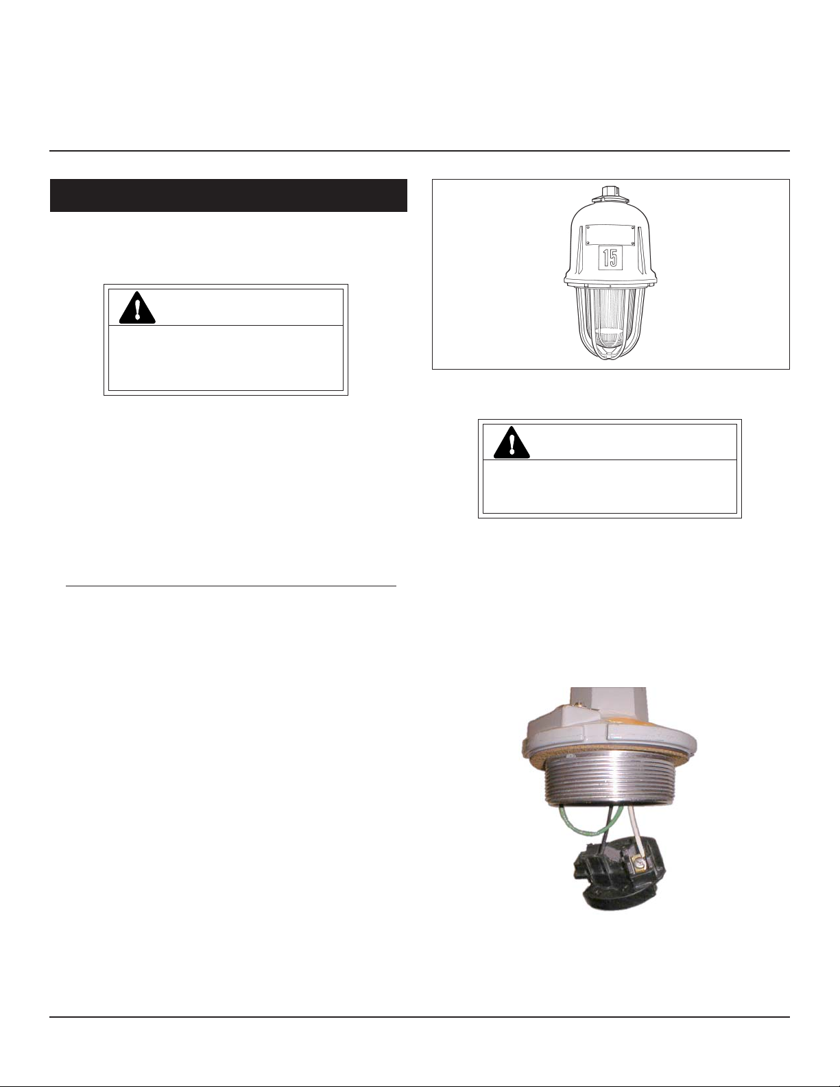
This luminaire is designed for application in hazardous
location environments.
Lighting Solutions
WARNING
Risk of electric shock
• Turn power off before servicing
– see instructions
GEH-5850
INSTRUCTIONS
POWR•GARD® LUMINAIRE
Make all electrical connections in accordance with
the National Electrical Code and any applicable
local code requirements.
THE OPERATING TEMPERATURE “T-CODE”
LISTED FOR THIS LUMINAIRE IS BASED ON THE
FOLLOWING BULB SIZES. USE OF OTHER THAN
THESE MAY RESULT IN A HIGHER OPERATING
TEMPERATURE AND COULD RESULT IN A HAZARDOUS CONDITION.
LAMP TYPE WATTAGE BULB SIZE
HIGH PRESSURE SODIUM 70,100,150 ED 23 1/2
HIGH PRESSURE SODIUM 250, 400 ED 18
METAL HALIDE/MERCURY 175, 250 ED 28
METAL HALIDE/MERCURY 400 ED 37
CAUTION: Check the operating temperature limits
marked on the ballast assembly prior to installation to be sure it conforms to the environmental
temperature restrictions and NEC classifications.
WARNING: TO PREVENT IGNITION OF HAZARDOUS ATMOSPHERES, DISCONNECT THE SUPPLY
CIRCUIT FROM THE LUMINAIRE BEFORE RELAMPING, REMOVING, OR PERFORMING ANY MAINTENANCE.
INSTALLATION
CAUTION
Unit will fall if not installed properly
• Follow installation instructions
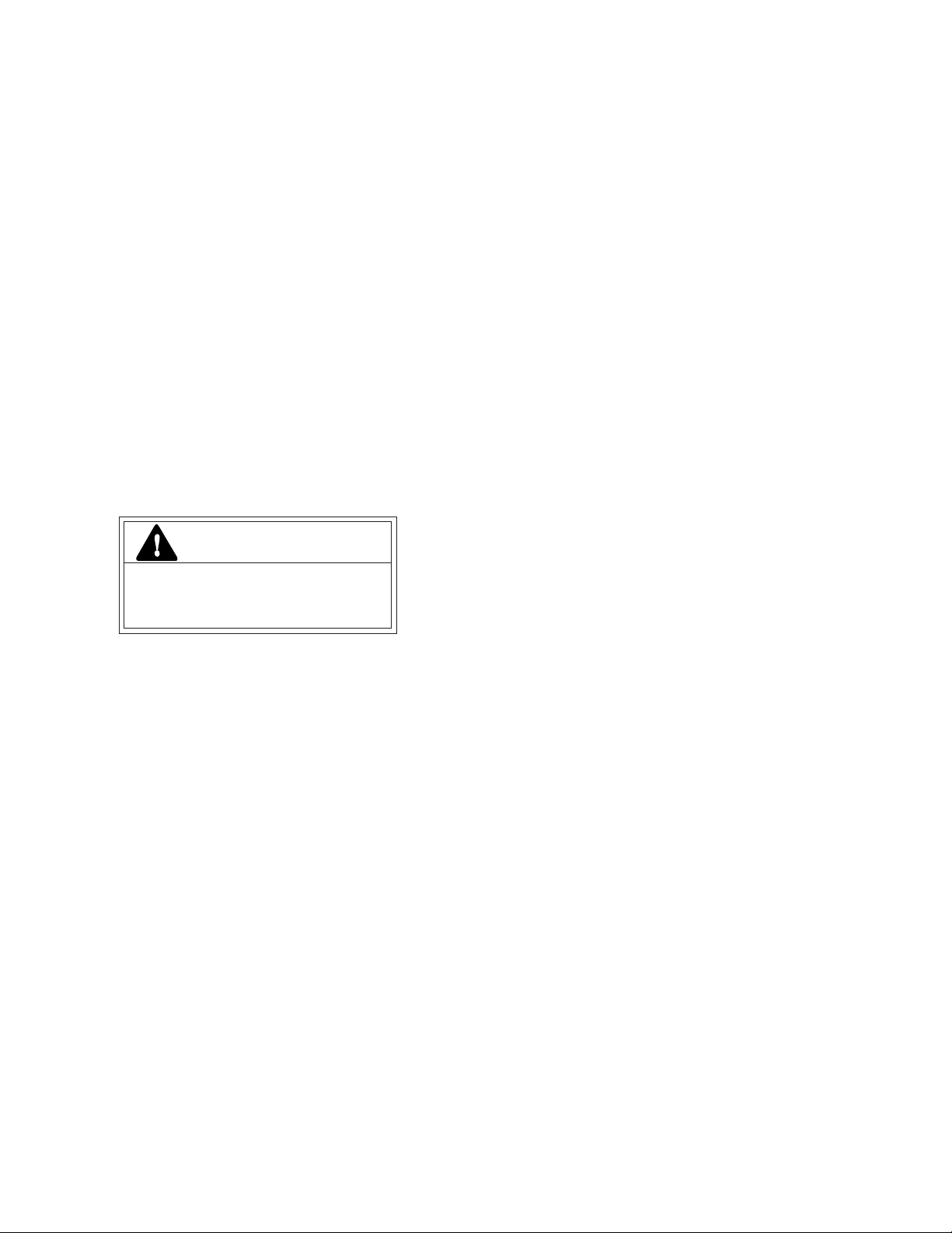
MOUNTING CONDUIT
Take the mounting hub and remove the electrical
disconnect from it. Thread the mounting hub onto the
conduit five threads minimum and tighten the set screw.
Connect the ground lead to the screw provided in the
mounting hub.
Connect the supply wires to the electrical disconnect
according to the color coding labels if applicable. Refasten
the disconnect into the mounting hub. See Figure A.
UNPACKING
The ballast assembly and mounting fittings have been
properly packed in separate cartons so that no parts should
have been damaged during transit. Remove packing
materials used to protect threads and inspect. Do not
attempt to assemble or use parts with damaged threads.
Verify that supply voltage is correct by comparing it
to nameplate.
These instructions do not purport to cover all details or variations in equipment nor to provide for every possible contingency to be met in connection with installation, operation or
maintenance. Should further information be desired or should particular problems arise which are not covered sufficiently for the purchaser’s purposes, the matter should be referred
to GE Lighting Solutions.
Figure A
MOUNTING STANCHION
AND WALL BRACKET
For the stanchion arm, mount arm onto the conduit five
threads minimum and tighten the set screw. For the wall
bracket, attach bracket to the support surface through the
Page 2
four clearance holes provided. Remove the electrical
disconnect from the mounting hub and connect electrically
as stated for conduit mounting.
EXTERNAL REFLECTORS
A reflector, if used, is attached to the bottom of the globe
ring with the three screws provided.
MOUNTING SURFACE
Attach the surface mounting box to the support surface
through the four clearance holes provided. Remove the
electrical disconnect from the mounting hub and connect
electrically as stated for conduit mounting.
NOTE: Threads on the ballast housing to ac-
cept the above mountings are factory
lubricated with General Electric Versalube
G322L. Additional lubricant of the same type
may be applied if necessary.
BALLAST HOUSING
Thread the ballast housing onto the hub. The electrical
disconnect will automatically mate after five threads have
engaged. Continue engaging until the housing is tightly
threaded onto the hub and then tighten the set screw at the
bottom of the hub.
LAMP INSTALLATION
CAUTION
Risk of burn
• Allow lamp/fixture to cool before
handling
If a globe guard is on the unit, the reflector is attached
using the same screws that hold the guard. These screws
need only be loosened since the reflector is provided with
keyhole slots.
If an angle reflector is used, orient the reflector with
respect to the three screws so that the main light output is
near the desired direction. After loosening the set screw the
globe ring can then be slightly rotated to complete the
reflector orientation. Then retighten the set screw.
MAINTENANCE
It will occasionally be necessary to clean the optical
assembly in order to maintain the light level. Frequency of
cleaning will depend on the dirt level in the user’s facility
and the minimum light level which is acceptable to him.
The reflector should be cleaned with any suitable nonabrasive solution of water and soap or detergent. Residual
cleanser should be removed by clean water rinsing. The
glassware may be cleaned with any conventional glass
cleanser.
Disconnect the power supply circuit before relamping.
Loosen the set screw near the bottom edge of the ballast
housing. Unthread the glass globe support ring which
threads into the ballast housing. To assist in removing this
globe ring, a screw driver can be inserted in the pry slots, or
the globe ring can be loosened by lightly tapping on the
globe ring ribs.
Use only lamps specified on nameplate. Observe
lamp manufacturer’s recommendations and restric-
tions on lamp operation, particularly ballast type,
burning position, etc.
Damage may occur to the fixture if the lamp is inserted
while power is on, or if the lamp is not tight in the socket
when power is applied.
LAMP TIGHTNESS: The lamp should be securely
inserted to the NEMA-EEI specified torque of 35 inchpounds, which is best achieved by very firmly tightening to
insure application of sufficient torque. Tightening must be
sufficient to fully depress and load the center contact of the
socket.
After lamp is installed, rethread globe ring into ballast
housing until it firmly seats. Tighten set screw.
WARNING: GLOBE IS TEMPERED
GLASS. DO NOT SCRATCH OR CHIP.
Page 3

GE
g
À LIRE AVEC SOIN AVANT D’INSTALLER
PRÉSENTATION
Ce luminaire estconçu pour une application dans les
environnements dangereux.
Lighting Solutions
DANGER
Risque d’électrocution
• Mettre hors tension avant d’intervenir
– Suivez les instructions
Effectuez tous les raccordements en conformité avec les
normes nationales et les éventuels règlements locaux
applicables.
LA TEMPÉRATURE NOMINALE“T-CODE” LISTÉE POUR CE
LUMINAIRE EST BASÉE SUR LES TAILLES D’AMPOULES
SUIVANTES. SI VOUS EN UTILISIEZ DE DIFFÉRENTES,
CELA POURRAIT AMENER UNE TEMPÉRATURE DE
FONCTIONNEMENT PLUS ÉLEVÉE ET PROVOQUER UNE
SITUATION DANGEREUSE.
TYPE DE LAMPE PUISSANCE TAILLE
SODIUM HAUTE PRESSION 70,100,150 ED 23 1/2
SODIUM HAUTE PRESSION 250, 400 ED 18
HALOGÈNURE/MERCURE 175, 250 ED 28
HALOGÈNURE/MERCURE 400 ED 37
ATTENTION: Vérifiez la température limite de
fonctionnement avant de l’installer pour vérifier qu’il
compatible avec les restrictions de température de
l’environnement et les normes NEC.
GEH-5850
INSTRUCTIONS
®
LUMINAIRE POWR•GARD
INSTALLATION
ATTENTION
Risque de chute en cas de mauvais
montage • Suivez les instructions
MONTAGE SUR CONDUITE
Prenez le raccord de montage et débranchez-en la déconnexion
électrique rapide. Vissez-le sur la conduite sur au moins cinq filets et
serrez la vis de blocage. Raccordez le fil de terre sur la vis disponible
dans le raccord de montage.
Connectez les fils d’alimentation sur la prise de déconnexion
électrique en fonction de leurs marquages de couleur s’il y a lieu.
Rebranchez la prise à déconnexion rapide dans le raccord de
montage (voir schéma A).
AVERTISSEMENT : POUR ÉVITER UNE INFLAMMATION
EN ATMOSPHÈRE DANGEREUSE, DÉBRANCHEZ
L’ALIMENTATION DU LUMINAIRE AVANT DE CHANGER
SA LAMPE, DE LE DÉMONTER OU D’OPÉRER TOUT
ENTRETIEN DESSUS.
DÉBALLAGE
L’ensemble de ballast et les dispositifs de montage ont été
correctement emballés dans des cartons séparés de façon à ce
qu’aucune pièce ne soit détériorée durant le transport. Enlevez les
matériaux d’emballage utilisés pour protéger les filetages et
inspectez. N’essayez pas d’assembler ou d’utiliser des pièces avec
des filets endommagés.
Schéma A
MONTAGE AVEC MONTANT
Vérifiez que la tension secteur disponible est la bonne en
comparant avec l'indication de tension sur la plaque
d'identification.
Ces instructions n'ont pas pour destination de couvrir tous les détails ou variantes de l'équipement, ni de répondre à toutes les éventualités que vous pourriez rencontrer pendant l'installation,
le fonctionnement ou l'entretien. Si vous souhaitez des informations complémentaires, ou si vous rencontrez un problème particulier qui ne soit pas adressé de votre point de vue d'acheteur,
le sujet doit être remonté jusqu'à la société GE Lighting Solutions
ET SUPPORT MURAL
Pour le bras de montant, montez le bras sur la conduite sur cinq
filets au minimum et serrez la vis de blocage. Pour le support mural,
fixez-le sur la surface de support en utilisant les quatre orifices de
dégagement disponibles.
Page 4

Débranchez la prise électrique à déconnexion rapide du raccord
de montage et faites le raccordement électrique comme expliqué
pour le montage sur conduite.
MONTAGE EN SURFACE
Fixez la boîte de montage en surface sur la surface d’accueil en
utilisant les quatre trous de dégagement disponibles. Débranchez la
prise électrique à déconnexion rapide du raccord de montage et
faites le raccordement électrique comme expliqué pour le montage
sur conduite.
NOTE : Les filets sur le caisson de ballast compatible avec
les types de montages précédents sont lubrifiés avec du
Versalube G322L de General Electric. Appliquez un
supplément de lubrifiant du même type si nécessaire.
Une fois la lampe installée, revissez à fond l’anneau de
globe sur le caisson de ballast. Serrez la vis de blocage.
AVERTISSEMENT : LE GLOBE EST EN VERRE
TREMPÉ, ÉVITEZ LES RAYURES ET COUPS.
RÉFLECTEURS EXTERNES
Un réflecteur, s’il est utilisé, est fixé sur le bas de l’anneau
de globe avec les trois vis fournies.
S’il y a une protection de globe sur le luminaire, le
réflecteur est fixé en utilisant les mêmes vis qui maintiennent
la protection. Ces vis n’ont seulement qu’à être desserrées
pour ce montage puisque le réflecteur est pourvus d’orifices de
montage en trous de serrure.
CAISSON DE BALLAST
Vissez le caisson de ballast sur le raccord de montage. La prise
électrique à déconnexion rapide va automatiquement se brancher
après que cinq filets aient été engagés. Continuez de visser jusqu’à ce
que le caisson soit bien serré sur le raccord de montage, puis serrez
la vis de blocage sur le bas du raccord.
INSTALLATION DE LAMPE
ATTENTION
Risque de brûlure
Laissez le bloc d’ampoule refroidir
avant d'y toucher
Débranchez l’alimentation électrique avant de remettre une
lampe. Desserrez la vis de blocage près du bord inférieur du caisson
de ballast. Dévissez le support du globe en verre qui est fixé sur le
caisson de ballast. Pour aider à enlever l’anneau de globe, une lame
de tournevis peut être insérée dans les fentes de levier, ou l’anneau
de globe peut être desserré en tapotant légèrement sur ses nervures.
N’utilisez que le type de lampe spécifié sur la plaque
d’identification. Observez les recommandations et restrictions
du fabricant sur le fonctionnement de la lampe, en particulier
pour le type de ballast, la position d’utilisation, etc.
Si un réflecteur coudé est utilisé, orientez-le en fonction
des trois vis de façon à ce que la sortie lumineuse principale
soit près de la direction voulue. Après desserrage de la vis de
blocage, l’anneau de globe peut alors être légèrement tourné
pour parfaire l’orientation du réflecteur. La vis de blocage est
ensuite resserrée.
ENTRETIEN
Il sera nécessaire à l'occasion de nettoyer l’ensemble optique pour
maintenir le niveau d'éclairage. La fréquence de ces nettoyages
dépend du niveau d'empoussièrage local et du seuil minimum de
luminosité acceptable pour l'utilisateur. Le réflecteur doit être lavé
avec une solution d'eau et de n'importe quel détergent ménager
doux et non abrasif, rincez à l'eau claire pour enlever les résidus de
nettoyant. Le vitrage peut être nettoyé avec un produit pour vitres
classique.
Des dommages peuvent se produire dans le luminaire si la lampe
est insérée quand il est encore sous tension, ou si la lampe était mal
serrée au moment de sa mise sous tension.
SERRAGE DE LAMPE : La lampe doit être insérée de façon
sûre avec un couple de serrage NEMA-EEI spécifié à 4,4 mkg (35
livre-pouce), ce qui est le mieux réalisé en serrant fortement à la
main pour mettre un couple suffisant. Le serrage doit complètement
appuyer et charger le contact central de la douille avec le culot de la
lampe.
GE Lighting Solutions • 1-888-MY-GE-LED • www.gelightingsolutions.com
16943533----888
GE Lighting Solutions is a subsidiary of the General Electric Company. Evolve and other trademarks belong to GE Lighting Solutions. The GE brand and logo are trademarks of the General Electric Company.
© 2011 GE Lighting Solutions. Information provided is subject to change without notice. All values are design or typical values when measured under laboratory conditions.
g
35-201578-6N (1/01)
 Loading...