

Page 1
GE
g
READ THOROUGHLY BEFORE INSTALLING
Lighting Solutions
WARNING
Risk of electric shock
• Turn power off before servicing
– see instructions
THE OPERATING TEMPERATURE “T-CODE”
LISTED FOR THIS LUMINAIRE IS BASED ON THE
FOLLOWING BULB SIZES. USE OF OTHER THAN
THESE MAY RESULT IN A HIGHER OPERATING
TEMPERATURE AND COULD RESULT IN A HAZARDOUS CONDITION.
LAMP TYPE WATTAGE BULB SIZE
GEH-5838A
INSTRUCTIONS
FILTR•GARD® H2 LUMINAIRE
HIGH PRESSURE SODIUM 70,100,150 ED 23 1/2
HIGH PRESSURE SODIUM 250, 400 ED 18
METAL HALIDE/MERCURY 175, 250 ED 28
METAL HALIDE/MERCURY 400 ED 37
AVERTISSEMENT: COUPER L’ALIMENTATION
AVANT L’INSTALLTION OU L’ENTRETIEN.
GENERAL
A complete luminaire consists of a ballast housing,
optical assembly, and a cover/mounting.
CAUTION: When installing luminaire in hazardous
locations check operating temperature limits prior
to installation to insure it conforms to the environmental temperature restrictions and CEC classifications.
MOUNTING INSTALLATION
CAUTION
Unit will fall if not installed properly
• Follow installation instructions
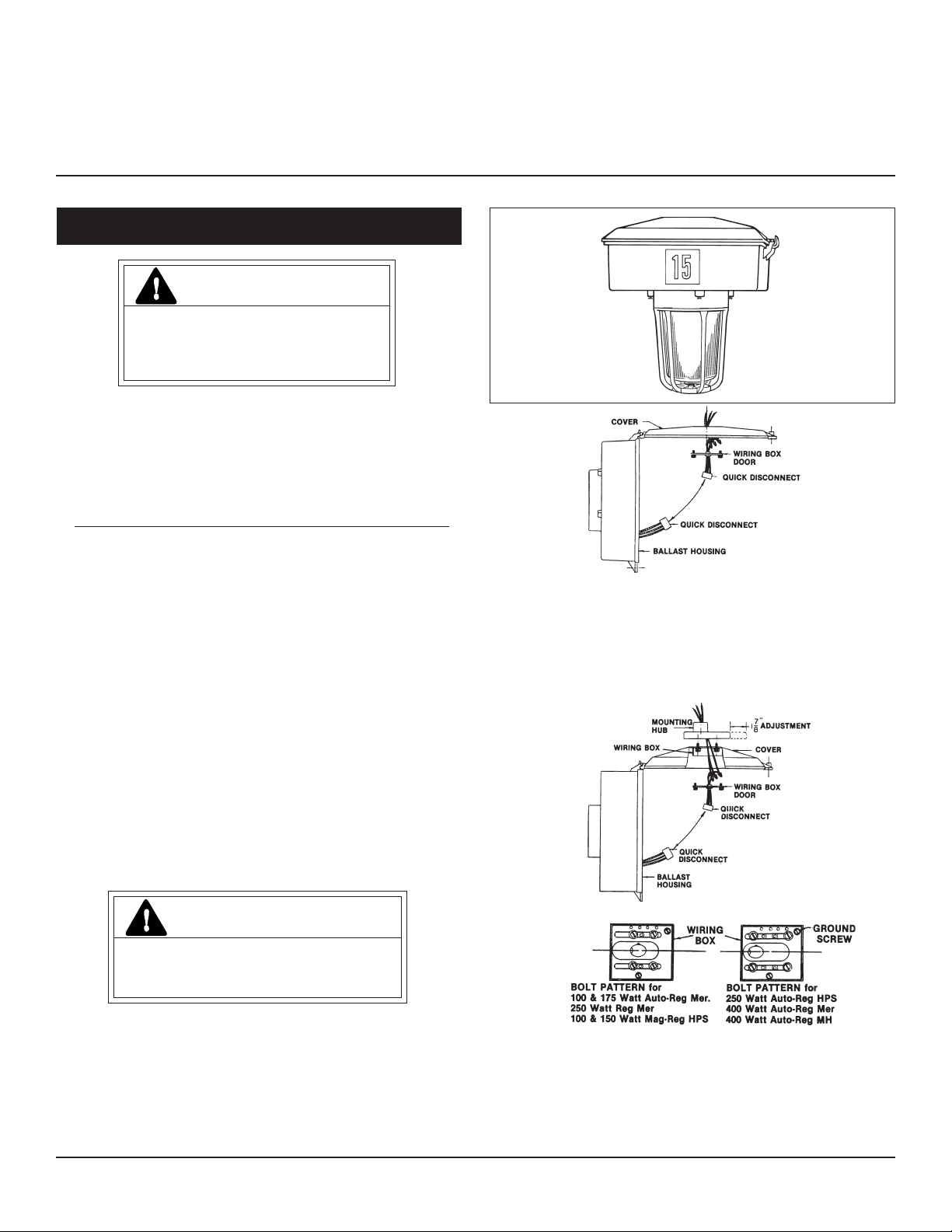
Figure 1
Flexible Cover (See Figures 2 and 3)—Remove wiring
box door. Loosen four (4) bolts holding mounting hub to
cover. Position adapter plate correctly to balance luminaire. Use widest bolt spacing possible to secure plate cover.
Wiring should be accomplished in accordance with accepted practice. Factory attached ground lead is provided.
After wiring, replace the wiring box door.
Figure 2
Figure 3
Pendant (See Figure 1)—Remove wiring box door, and
thread cover onto conduit. Orient cover, seal around the
conduit using approved procedures. Tighten set screw at
mounting hub. Wiring should be accomplished in accordance with accepted practices. A factory attached ground
lead is provided. After wiring, replace the wiring compartment door.
These instructions do not purport to cover all details or variations in equipment nor to provide for every possible contingency to be met in connection with installation, operation or
maintenance. Should further information be desired or should particular problems arise which are not covered sufficiently for the purchaser’s purposes, the matter should be referred
to GE Lighting Solutions.
Ceiling Cover (See Figure 4)—using the tabs, mount
cover to ceiling and remove wiring box door. Wiring
should be accomplished in accordance with accepted
practices. Factory attached ground lead is provided. After
wiring, replace the wiring box door.
Page 2
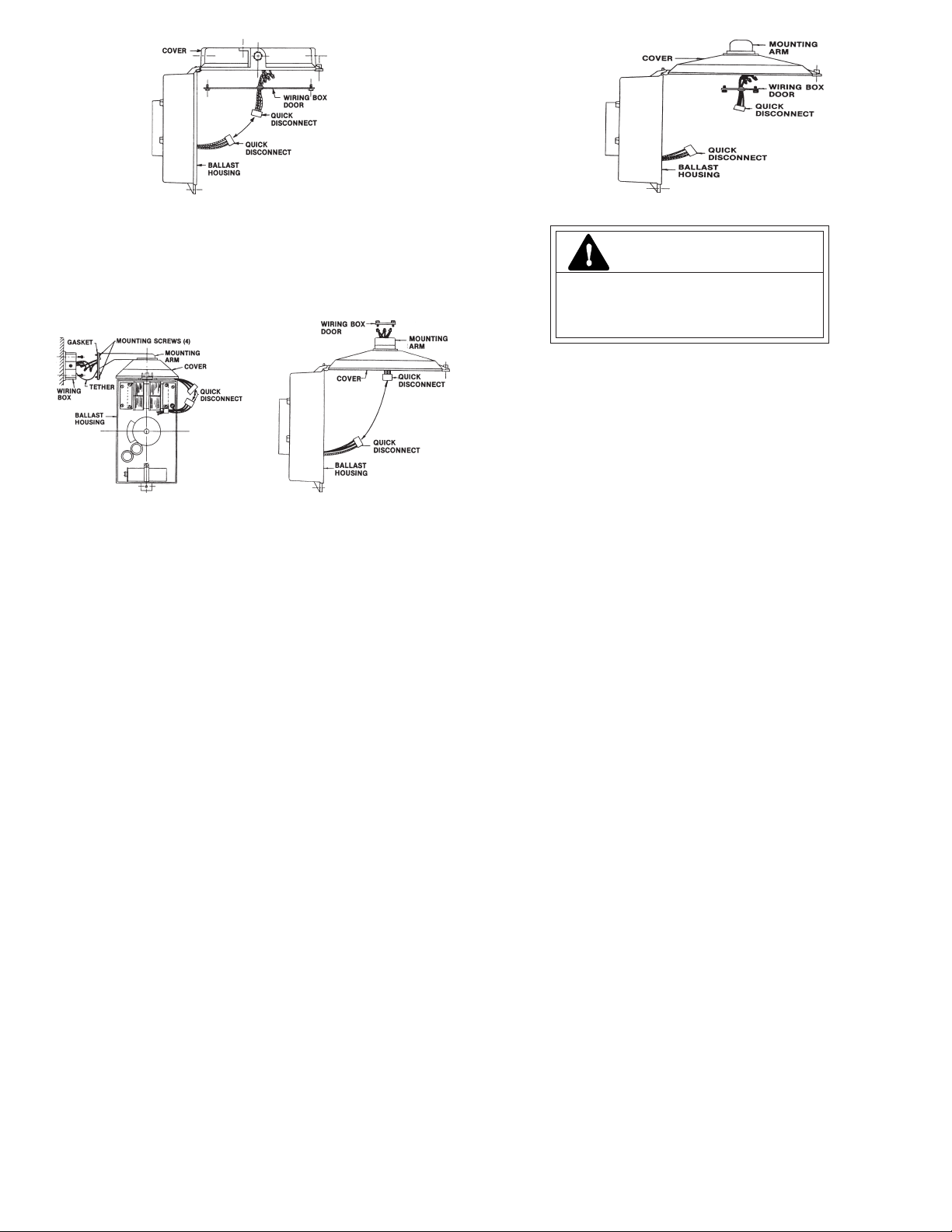
Figure 4
Figure 7
Wallmount Cover (See Figure 5)—Mount wiring box
and pull leads. Tether is supplied to hold arm assembly
while wiring. Wiring should be accomplished in accordance with accepted practices. Factory attached ground
lead is provided. After wiring, attach arm assembly to
wiring box. Do not damage gasket attached to arm assembly. Mounting screws should be tightened in alternate
sequence.
Figure 5 Figure 6
Straight Stanchion Cover (See Figure 6)—Remove the
wiring box door. Attach mounting arm onto conduit.
Wiring should be accomplished in accordance with accepted practices. Factory attached ground lead is provided.
After wiring, replace the wiring box door.
Angle Stanchion Cover (See Figure 7)—Remove the
wiring box door. Attach mounting arm onto conduit.
Wiring should be accomplished in accordance with accepted practices. Factory attached ground lead is provided.
After wiring, replace the wiring box door.
WIRING
Make all electrical connections in accordance with
the National Electrical Code and any applicable
local code requirements.
Verify that supply voltage is correct by comparing it
to nameplate.
When changing voltage on reconnectable units,
move only the lead with the insulated connector.
IF SINGLE VOLTAGE:
All single voltage ballasts are pre-wired such that user
need only connect the supply conductors.
IF MULTIVOLT: (120/208/240/277 volts)
Connect the ballast lead with the insulated terminal to
the desired voltage terminal as indicated on the ballast
terminal nameplate.
IF MULTIWATT:
Multiwatt ballasts are available in various combinations
of wattage. See wiring instructions on wiring tag inside
the luminaire.
BALLAST HOUSING INSTALLATION
Slip ballast housing hinge pin over cover hinge. Mate
electrical connectors and swing unit shut. Tighten ballast
cover screw securely.
LAMP INSTALLATION
CAUTION
Risk of burn
• Allow lamp/fixture to cool before
handling
Use only lamps specified on nameplate. Observe
lamp manufacturer’s recommendations and restrictions on lamp operation, particularly ballast type,
burning position, etc.
Lamp Tightness – Mogul Base Lamp: The lamp should
be securely inserted to the NEMA-EEI specified torque of 35
inch-pounds, which is best achieved by very firmly
tightening to insure application of sufficient torque.
Tightening must be sufficient to fully depress and load the
center contact of the socket.
Lamp Tightness – Medium Base Lamp: The lamp
should be tightened to a light firmness sufficient to depress
the center contact.
OPTICALS
CAUTION: GLOBE IS TEMPERED GLASS. DO NOT
SCRATCH OR CHIP.
Glass Globe—Attach globe by threading firmly into
bottom of ballast housing.
Industrial Reflector Type EN—Thread reflector firmly
into ballast housing. Lamp may be replaced via glass
clampband assembly.
Prismatic Refractor Assembly Type V, R or L—Thread
adaptor firmly into housing ballast housing. To orient
asymmetrical glass, loosen clamping screws, turn glass and
retighten screws. To relamp, unscrew complete optical
from ballast housing.
ACCESSORIES
External Reflectors—Insert mounting screws. Orient
reflector to proper position and slip over mounting screws.
Turn reflector and tighten screws securely.
Globe Guard—Insert protective guard into ballast
housing and turn until retained by detent.
MAINTENANCE
It will occasionally be necessary to clean optical assembly
in order to maintain light levels. Frequency of cleaning will
depend on dirt levels in user’s facility and minimum light
levels which are acceptable. Reflector should be cleaned
with any suitable non-abrasive solution of water and soap or
detergent. Residual cleaning agent should be removed with
clean water rinsing. Glassware may be cleaned with any
conventional glass cleaner. If unit gets soiled on inside, it
should be cleaned and any damaged gasket or filter replaced.
Page 3

GE
g
À LIRE AVEC SOIN AVANT D’INSTALLER
Lighting Solutions
DANGER
Risque d’électrocution
• Mettre hors tension avant d’intervenir
– Suivez les instructions
LA TEMPÉRATURE NOMINALE“T-CODE” LISTÉE POUR CE
LUMINAIRE EST BASÉE SUR LES TAILLES D’AMPOULES
SUIVANTES. SI VOUS EN UTILISIEZ DE DIFFÉRENTES,
CELA POURRAIT AMENER UNE TEMPÉRATURE DE
FONCTIONNEMENT PLUS ÉLEVÉE ET PROVOQUER UNE
SITUATION DANGEREUSE.
TYPE DE LAMPE PUISSANCE
TAILLE
SODIUM HTR PRESSION 70,100,150 ED 23 1/2
SODIUM HTR PRESSION 250, 400 ED 18
HALOGÈNURE/MERCURE 175, 250 ED 28
HALOGÈNURE/MERCURE 400 ED 37
AVERTISSEMENT : COUPEZ L’ALIMENTATION
AVANT L’INSTALLATION OU L’ENTRETIEN.
PRÉSENTATION
Un luminaire complet comporte un logement de ballast, un
assemblage optique et un couvercle/support.
ATTENTION : Si vous installez ce luminaire dans des
endroits dangereux, vérifiez la température limite de
fonctionnement avant de l’installer pour vérifier qu’il
compatible avec les restrictions de température de
l’environnement et les normes CEC.
GEH-5838A
INSTRUCTIONS
LUMINAIRE FILTR•GARD® H2
COUVERCLE
PORTE BOîTE DE CÂBLAGE
DÉCONNEXION
RAPIDE
DÉCONNEXION
RAPIDE
LOGEMENT DE BALLAST
Schéma 1
Couvercle flexible (Voir schémas 2 et 3)—Ôtez la porte de la
boîte de câblage. Desserrez les 4 boulons tenant l’axe de
montage sur le couvercle. Positionnez bien la plaque d’adapteur
pour équilibrer le luminaire. Utilisez l’écartement entre boulons le
plus grand possible pour fixer la plaque de couverture. Le
câblage doit être réalisé en conformité avec les pratiques
officielles. Une liaison de terre est fournie en sortie d’usine. Après
le raccordement refermez la porte de la boîte de câblage.
AXE DE MONTAGE
BOÎTE DE CÂBLAGE
RÉGLAGE
COUVERCLE
PORTE BOÎTE DE
CÂBLAGE
INSTALLATION/MONTAGE
DÉCONNEXION
RAPIDE
ATTENTION
Risque de chute en cas de mauvais
montage • Suivez les instructions
Schéma 2
DISPOSITION pour:
LOGEMENT DE BALLAST
BOÎTE DE
CÂBLAGE
VIS DE TERRE
Pendant (Voir schéma 1)—Ôtez la porte de la boîte
de câblage, et vissez le couvercle sur la conduite. Orientez
le couvercle, faites l’étanchéité autour du conduit en
utilisant des procédures approuvées. Serrez la vis de
blocage de l’axe de montage. Le câblage doit être réalisé
en conformité avec les pratiques officielles. Une liaison de
terre est fournie en sortie d’usine. Après le raccordement
refermez la porte de la boîte de câblage.
Ces instructions n'ont pas pour destination de couvrir tous les détails ou variantes de l'équipement, ni de répondre à toutes les éventualités que vous pourriez rencontrer pendant l'installation,
le fonctionnement ou l'entretien. Si vous souhaitez des informations complémentaires, ou si vous rencontrez un problème particulier qui ne soit pas adressé de votre point de vue d'acheteur,
le sujet doit être remonté jusqu'à la société GE Lighting Solutions
Schéma 3
Couvercle de plafond (Voir schéma 4)—En utilisant les
pattes, montez le couvercle au plafond et enlevez la porte de la boîte de
câblage. Le câblage doit être réalisé en conformité avec les pratiques
officielles. Une liaison de terre est fournie en sortie d’usine. Après le
raccordement refermez la porte de la boîte de câblage.
Page 4

COUVERCLE
COUVERCLE
BRAS DE MONTAGE
PORTE BOÎTE DE CÂBLAGE
DÉCONNEXION RAPIDE
DÉCONNEXION RAPIDE
LOGEMENT DE BALLAST
Schéma 4
Couvercle sur mur (Voir schéma 5)—
câblage et tirez les fils. Une attache est fournie pour tenir
l’assemblage de bras pendant le câblage. Le câblage doit être
réalisé en conformité avec les pratiques officielles. Une liaison de
terre est fournie en sortie d’usine. Ensuite fixez le bras (sans
abîmer le joint qui y est attaché). Les vis de montage doivent
être serrées en séquence alternative.
VIS DE FIXATION (4)
BOÎTE DE
CÂBLAGE
LOGEMENT DE
JOINT
ATTACHE
BALLAST
BRAS DE
MONTAGE
COUVERCLE
DÉCONNEXION
RAPIDE
Schéma 5
Montez la boîte de
PORTE BOÎTE
DE CÂBLAGE
COUVERCLE DÉCONNEXION
LOGEMENT DE
BALLAST
DÉCONNEXION
RAPIDE
BRAS DE
MONTAGE
RAPIDE
Schéma 6
Couvercle sur poteau droit (Voir schéma 6)—Enlevez la
boîte de câblage. Fixez le bras de montage sur la conduite. Le
câblage doit être réalisé en conformité avec les pratiques
officielles. Une liaison de terre est fournie en sortie d’usine. Après
le raccordement refermez la porte de la boîte de câblage.
Couvercle sur poteau coudé (Voir schéma 7)—Enlevez la
boîte de câblage. Fixez le bras de montage sur la conduite. Le
câblage doit être réalisé en conformité avec les pratiques
officielles. Une liaison de terre est fournie en sortie d’usine. Après
le raccordement refermez la porte de la boîte de câblage.
CÂBLAGE
Effectuez tous les raccordements en conformité avec les normes
nationales et les éventuels règlements locaux applicables.
Vérifiez que la tension secteur disponible est la bonne en
comparant avec l'indication de tension sur la plaque
d'identification.
PORTE BOÎTE
DE CÂBLAGE
DÉCONNEXION
RAPIDE
Schéma 7
DÉCONNEXION RAPIDE
LOGEMENT DE
BALLAST
ATTENTION
Risque de brûlure
• Laissez le bloc d’ampoule refroidir
avant d’y toucher
INSTALLATION DE LA LAMPE
N’utilisez que le type de lampe spécifié sur la plaque
d’identification. Observez les recommandations et restrictions du
fabricant sur le fonctionnement de la lampe, en particulier pour le
type de ballast, la position d’utilisation, etc.
Serrage de lampe - culot goliath : La lampe doit
être insérée de façon sûre avec un couple de serrage NEMA-EEI
spécifié à 4,4 mkg (35 livre-pouce), ce qui est le mieux réalisé en
serrant fortement à la main pour mettre un couple suffisant. Le
serrage doit complètement appuyer et charger le contact central
de la douille avec le culot de la lampe.
Serrage de lampe – culot moyen : La lampe doit être
serrée fermement sans forcer pour enfoncer le contact central de
la douille.
OPTIQUES
ATTENTION : LE GLOBE EST EN VERRE TREMPÉ,
ÉVITEZ LES RAYURES ET COUPS.
Globe en verre—Fixez le globe en le vissant fermement sur
le bas du logement de ballast.
Réflecteur industriel type EN—Vissez fermement le
réflecteur sur le logement de ballast. La lampe pourra être
remplacée via l’assemblage de bande de serrage de verre.
Assemblage de réflecteur prismatique type V, R ou
L—Vissez fermement le réflecteur sur le logement de ballast. Pour
orienter les verres asymétriques, desserrez les vis de maintien,
tournez le verre et resserrez. Pour changer de lampe dévissez
toute l’optique du logement de ballast.
En changeant la tension des unités reconfigurables, ne bougez
que le fil avec la cosse isolée.
MONO-TENSION :
Tous les ballasts sont précâblés et l'utilisateur n'a qu'à relier
les fils d'alimentation pour la tension prévue.
MULTI-TENSIONS : (120/208/240/277 volts)
Reliez le fil de ballast avec sa terminaison isolée sur la borne
de tension adéquate comme indiqué sur la plaque du ballast.
MULTI-PUISSANCES :
Les ballasts multi-puissances sont disponibles en diverses
combinaisons de wattages. Reportez-vous aux instructions de
câblage sur l'étiquette à l'intérieur du luminaire.
INSTALLATION DU LOGEMENT DE BALLAST
Emboîtez par leur charnière le logement de ballast et le
couvercle. Appairez les conducteurs électriques et fermez le
luminaire. Serrez bien les vis du couvercle de ballast.
GE Lighting Solutions • 1-888-MY-GE-LED • www.gelightingsolutions.com
16943533----888
GE Lighting Solutions is a subsidiary of the General Electric Company. Evolve and other trademarks belong to GE Lighting Solutions. The GE brand and logo are trademarks of the General Electric Company.
© 2011 GE Lighting Solutions. Information provided is subject to change without notice. All values are design or typical values when measured under laboratory conditions.
g
ACCESSOIRES
Réflecteurs externes—Insérez les vis de fixation. Orientez
le réflecteur en bonne position et enfilez-le sous les vis. Tournez
le réflecteur puis serrez bien les vis.
Protège globe—Inserez la protection dans le logement de
ballast, tournez-la pour qu’elle soit retenue par encliquetage.
ENTRETIEN
Il sera nécessaire à l'occasion de nettoyer l’ensemble optique
pour maintenir le niveau d'éclairage. La fréquence de ces
nettoyages dépend du niveau d'empoussièrage local et du seuil
minimum de luminosité acceptable pour l'utilisateur. Le réflecteur
doit être lavé avec une solution d'eau et de n'importe quel
détergent ménager doux et non abrasif, rincez à l'eau claire pour
enlever les résidus de nettoyant. Le vitrage peut être nettoyé
avec un produit pour vitres classique. Si le luminaire devenait sale
à l'intérieur, nettoyez-le et remplacez tout joint ou filtre détérioré.
35-201578-3M (12/00)
 Loading...