

Page 1
ge.com
184D1065P002 49-50233 10-07 JR
GXSL55F
GXSV65F
Safety Instructions . . . . . . . . . . . .2
System Overview . . . . . . . . . . .3–7
Installation Instructions . .7–15
Battery Installation . . . . . . . . . . . . . . .14
Faucet Installation . . . . . . . . . . . . . . . .10
Filter Replacement . . . . . . . . . . . . . . .15
Flush Procedure . . . . . . . . . . . . . . . . . .15
Installing the Tubing . . . . . . . . . . . . . .13
System Installation . . . . . . . . . . .11, 12
Water Supply . . . . . . . . . . . . . . . . . . .8, 9
Troubleshooting Tips . . . . . . . .16
Consumer Support . . . . . . . . . . .20
GXSL55F
GXSV65F
Instrucciones de seguridad
. . . . .2
Generalidades del sistema
. . . .3–7
Instrucciones de instalación . .
7–15
Instalación de la batería . . . . . . . . . .14
Instalación de la tubería . . . . . . . . . .13
Instalación del grifo . . . . . . . . . . . . . .10
Instalación del sistema . . . . . . . .11, 12
Procedimiento para lavar . . . . . . . . .15
Reposición del filtro . . . . . . . . . . . . . . .15
Suministro del agua . . . . . . . . . . . . .8, 9
Consejos para la solución
de problemas . . . . . . . . . . . . . . . . .17
Apoyo al consumidor . . . . . . . .19
Manual del propietario
e instalación
Owner’s Manual and
Installation Instructions
Water Filtration System
Sistema de Filtración de Agua
GXSL55F is Tested and Certified by NSF
International against NSF/ANSI Standard 42
for the reduction of Chlorine: Taste and Odor
and Particulate Class I and Standard 53 for the
reduction of Lead, Cyst , Turbidity, Asbestos,
Mercury, Lindane, Atrazine, Toxaphene and 2,4-D.
GXSV65F is Tested and Certified by NSF
International against NSF/ANSI Standard 42
for the reduction of Chlorine: Taste and Odor
and Particulate Class I and Standard 53 for the
reduction of Lead, Cyst , Turbidity, Asbestos,
Mercury, Lindane, Atrazine, Benzene and VOC.
El modelo GXSL55F se ha sometido a la prueba y
ha recibido la certificación de NSF International
contra la norma 42 de NSF/ANSI para la reducción
de cloro: sabor y olor y clase I de partículas y la
norma 53 para la reducción de plomo, quistes,
turbidez, amianto, mercurio, lindano, atrazina,
toxafeno y 2,4-D.
El modelo GXSV65F se ha sometido a la prueba y
ha recibido la certificación de NSF International
contra la norma 42 de NSF/ANSI para la reducción
de cloro: sabor y olor y clase I de partículas y la
norma 53 para la reducción de plomo, quistes,
turbidez, amianto, mercurio, lindano, atrazina,
bencina y VOC.
Page 2
2
IMPORTANT SAFETY INFORMATION.
READ ALL INSTRUCTIONS BEFORE
USING.
WARNING:
For your safety, the information in this manual
must be followed to minimize the risk of property damage or personal
injury.
SAFETY PRECAUTIONS
■ Use the Water Filtration system on a potable, safe-to-drink, home COLD
water supply only. The filter canister will not purify the water, or make it
safe to drink.
■ Do not use on a hot water supply (100°F max.).
WARNING: Do not use with water that is microbiologically
unsafe or of unknown quality without adequate disinfection before or after
the system. Systems certified for cyst reduction may be used on disinfected
water that may contain filterable cysts.
PROPER INSTALLATION
This Water Filtration system must be properly installed and located in
accordance with the Installation Instructions before it is used.
■ Install or store where it will not be exposed to temperatures below
freezing or exposed to any type of weather. Water freezing in the system
will damage it. Do not attempt to treat water over 100°F.
WARNING: Discard all unused and packaging material after
installation. Small parts remaining after installation could be a choke hazard.
■ Your Water Filtration system will withstand up to 120 pounds per square
inch (psi) water pressure. If your house water supply pressure is higher
than 100 psi, install a pressure reducing valve before installing the Water
Filtration system.
READ AND FOLLOW THIS SAFETY
INFORMATION CAREFULLY.
SAVE THESE INSTRUCTIONS
INFORMACIÓN DE SEGURIDAD
IMPORTANTE.
LEA TODAS LAS INSTRUCCIONES ANTES
DE USAR.
ADVERTENCIA:
Para su seguridad, se deberá seguir la
información de este manual para minimizar el riesgo de daños a la
propiedad o lesiones personales.
PRECAUCIONES DE SEGURIDAD
■ Use el Sistema de Filtración de Agua solamente en un suministro de agua
potable FRÍA que sea segura para el consumo. El cartucho del filtro no
purificará el agua ni la hará segura para el consumo.
■ No use en un suministro de agua caliente (100°F Máx.).
ADVERTENCIA:
No use con agua que sea
microbiológicamente insegura o de calidad desconocida sin una desinfección
adecuada del sistema antes o después. Los sistemas certificados para la
reducción de esporas pueden ser usados en agua desinfectada que podría
contener esporas filtrables.
INSTALACIÓN CORRECTA
Este sistema de filtración debe ser instalado correctamente y ubicado según
las Instrucciones de instalación antes de su uso.
■ Instale o almacene donde no esté expuesto a temperaturas por debajo
del punto de congelación o expuesto a ningún tipo de inclemencia
atmosférica. Si el agua se congela en el sistema lo dañará. No intente
tratar el agua por encima de 100°F.
ADVERTENCIA: Deseche después de la instalación todos
los materiales de empaquetado y aquellos que no fueron usados. Las partes
pequeñas que sobren después de la instalación podrían representar un
peligro.
■ Su sistema de filtración de agua soportará hasta 120 libras por purgada
cuadrada (psi) de presión de agua. Si la presión del suministro de agua de
su casa es mayor de 100 psi, instale una válvula reductora de presión
antes de instalar el sistema de filtración de agua.
LEA YSIGA CUIDADOSAMENTE ESTA
INFORMACIÓN DE SEGURIDAD.
CONSERVE ESTAS INSTRUCCIONES
Page 3

3
Specifications Guidelines.
Many bad tastes and/or odors are removed from water using activated
carbon filter canisters. They are most often used to remove a chlorine taste
and odor. They can also reduce other undesirable elements from drinking
water supplies, such as organic chemical contaminants and lead.
NOTE: Small amounts of hydrogen sulfide (noticeable as “rotten egg” odor)
may be reduced by taste and odor filters for a short time, but the carbon
media is quickly exhausted. Other water conditioning equipment is usually
required for the continuous treatment of hydrogen sulfide.
The Water Filtration System Uses the Following
Canisters
Model GXSL55F
FQSLF Filter
(1200 gallon capacity)
Filter—White canisters with yellow band
• Reduces dirt, rust and sediment
• Reduces Chlorine: Taste and Odor
• Reduces Lead
• Reduces filterable Cysts (such as cryptosporidium and giardia)
• Reduces Turbidity
• Reduces Asbestos
• Reduces Mercury
• Reduces Lindane
• Reduces Atrazine
• Reduces Toxaphene
• Reduces 2,4-D
• 0.5–1 micron nominal particulate reduction
This system conforms to NSF/ANSI 42 and 53 for the specific performance
claims as verified and sustained by test data. See Performance Data Sheet
for details.
Pautas de las especificaciones.
Se pueden reducir muchos malos olores y/o sabores del agua usando
cartuchos de carbono para el filtro. Se usan principalmente para reducir el
olor y sabor a cloro. También pueden reducir otros elementos no deseados
del suministro de agua, tales como contaminantes químicos orgánicos y
plomo.
NOTA: Se pueden reducir por poco tiempo pequeñas cantidades de sulfuro
de hidrógeno como el olor a “huevo podrido” usando filtros de olor y sabor,
pero el medio de carbono se agota rápidamente. Por lo general, se requieren
otros equipos acondicionadores de agua para el tratamiento continuo del
sulfuro de hidrógeno.
El sistema de filtración de agua utiliza los siguientes
cartuchos
Modelo GXSL55F
Filtro FQSLF
(capacidad de 1200 galones)
Filtro—cartuchos blancos con banda amarilla
• Reduce la suciedad, el óxido y los sedimentos
• Reduce el sabor y olor a cloro
• Reduce el plomo
• Reduce los quistes filtrables (como cristosporidium y giardia)
• Reduce la turbidez
• Reduce el amianto
• Reduce el mercurio
• Reduce el lindano
• Reduce la atrazina
• Reduce el toxafeno
• Reduce 2,4-D
• Reducción nominal de partículas de 0,5–1 micrón
Este sistema se conforma a las normas 42 y 53 NSF/ANSI en cuanto
a las afirmaciones específicas de desempeño según verificación
y admisión de los datos de las pruebas. Consulte la hoja de datos del
desempeño para detalles.
Page 4
Specifications Guidelines.
The Water Filtration System Uses the Following
Canisters
Model GXSV65F
FQSVF Filter
(160 gallon capacity)
Filter—White canisters with green band
• Reduces dirt, rust and sediment
• Reduces Chlorine: Taste and Odor
• Reduces Lead
• Reduces filterable Cysts (such as cryptosporidium and giardia)
• Reduces Turbidity
• Reduces Asbestos
• Reduces Mercury
• Reduces Lindane
• Reduces Atrazine
• Reduces Benzene
• Reduces VOC
• 0.5–1 micron nominal particulate reduction
This system conforms to NSF/ANSI 42 and 53 for the specific performance
claims as verified and sustained by test data. See Performance Data Sheet
for details.
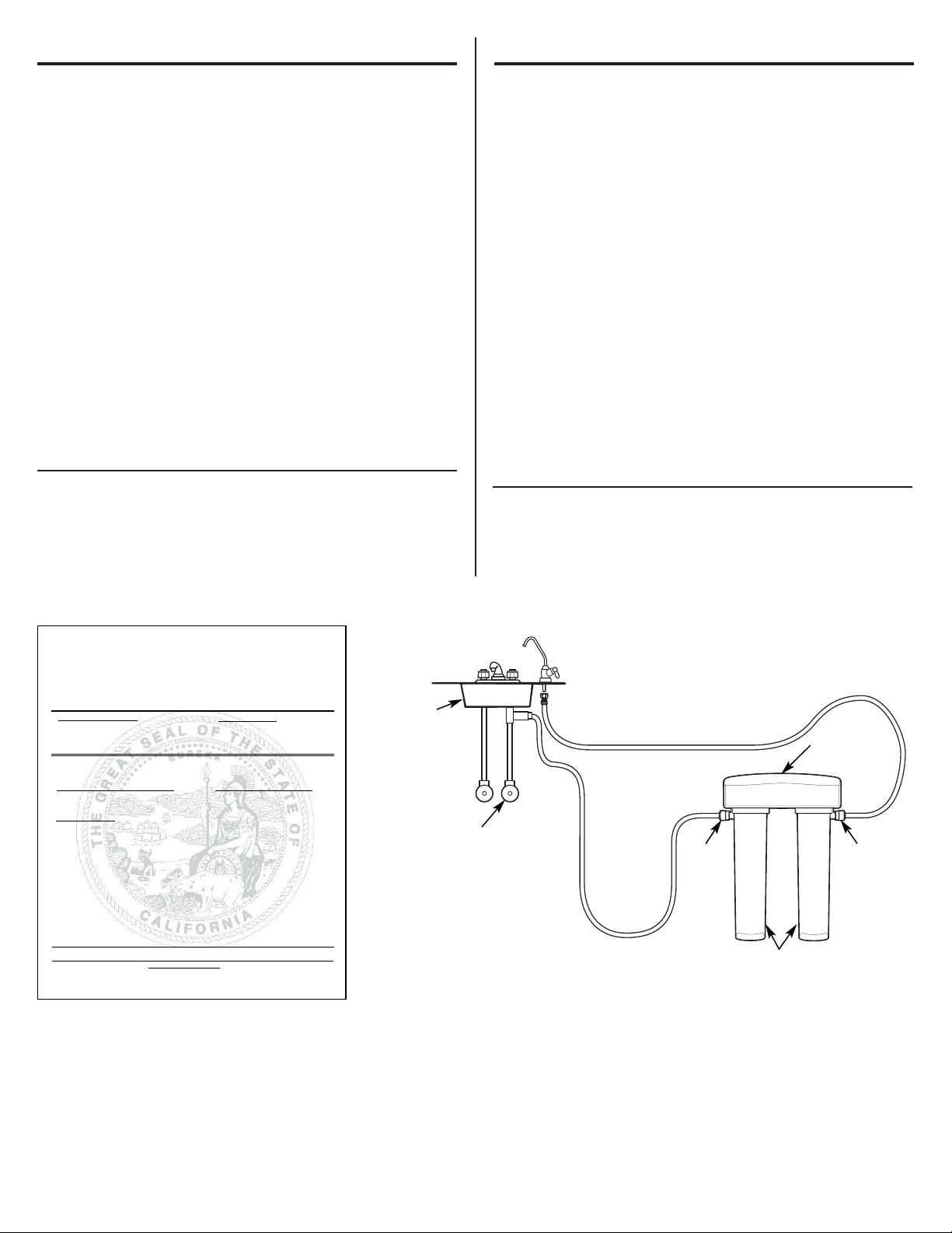
Installation Overview
Locate the drinking water system on the cold water supply pipe, under the
kitchen and/or bathroom sink, to filter the cold drinking water.
Pautas de las especificaciones.
El sistema de filtración de agua utiliza los siguientes
cartuchos
Modelo GXSV65F
Filtro FQSVF
(capacidad de 160 galones)
Filtro—cartuchos blancos con banda verde
• Reduce la suciedad, el óxido y los sedimentos
• Reduce el sabor y olor a cloro
• Reduce el plomo
• Reduce los quistes filtrables (como cristosporidium y giardia)
• Reduce la turbidez
• Reduce el amianto
• Reduce el mercurio
• Reduce el lindano
• Reduce la atrazina
• Reduce la bencina
• Reduce VOC
• Reducción nominal de partículas de 0,5–1 micrón
Este sistema se conforma a las normas 42 y 53 NSF/ANSI en cuanto a las
afirmaciones específicas de desempeño según verificación y admisión de
los datos de las pruebas. Consulte la hoja de datos del desempeño para
detalles.
Generalidades sobre la instalación
Coloque el sistema de agua potable en la tubería de suministro de agua fría,
debajo del lavaplatos de la cocina y/o del baño para filtrar el agua fría.
4
Water Supply Valve /
Válvula de suministro de agua
Filtered Water Faucet /
Grifo de agua filtrada
Inlet /
Entrada
Outlet /
Salida
Filter Canisters /
Cartuchos de los filtros
Manifold /
Recolector
Hot /
Caliente
Cold /
Fría
Sink /
Lavaplatos
State of California
Department of Health Services
Water Treatment Device
Certificate Number
160004 -
Date Issued: February 9, 2004
Trademark/Model Designation
GXSL55 F FQSLF
GQSL55 F FQSLF
Manufacturer: General Electric Company
The water treatment device(s) listed on this certificate have met the testing requirements pursuant to Section
116830 of the Health and Safety Code for the following health related contaminants:
Microbiological Contaminants and Turbidity
Cysts
Turbidity
Organic Contaminants
Atrazine
Lindane
2-4,D
Toxaphene
1200galRated Service Capacity: 0.78 gpmRated Service Flow:
Do not use where water is microbiologically unsafe or with water of unknown quality, except that systems certified for
cyst reduction may be used on disinfected waters that may contain filterable cysts.
Conditions of Certification:
Replacement Elements
Inorganic/Radiological Contaminants
Asbestos
Lead
Mercury
Page 5
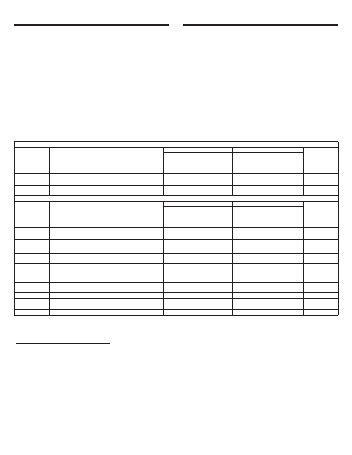
Performance Data Sheet.
SmartWater Filtration System GXSL55F
Using Filter FQSLF
■ This System has been tested according to NSF/ANSI 42 and 53 for the
reduction of the substances listed below. The concentration of the indicated
substances in water entering the system was reduced to a concentration
less than or equal to the permissible limit for water leaving the system, as
specified in NSF/ANSI 42 and 53.
■ Actual performance may vary with local water conditions.
■ Do not use with water that is microbiologically unsafe or with water of
unknown quality without adequate disinfection before or after the system.
Systems certified for cyst reduction may be used on disinfected waters that
may contain filterable cysts.
Hoja de datos de funcionamiento.
Cartucho FQSLF de sistema de filtración
GE SmartWater GXSL55F
■ Este sistema se ha sometido a las pruebas NSF/ANSI 42 y 53 a fin de reducir
las sustancias presentadas a continuación. Se redujo la concentración
de las sustancias indicadas en el agua que ingresan en el sistema a una
concentración menor o igual al limite permitido para el agua que sale del
sistema, como se especifica en NSF/ANSI 42 y 53.
■ El desempeño real puede variar de acuerdo a las condiciones locales
del agua.
■
No use con agua que sea microbiológicamente insegura o de calidad
desconocida sin una desinfección adecuada del sistema antes o después.
Los sistemas certificados para la reducción de esporas pueden ser usados
en agua desinfectada que podría contener esporas filtrables.
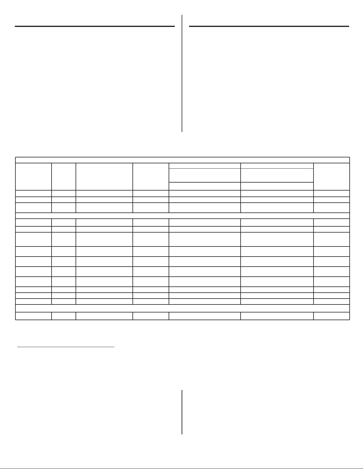
Standard No. 42: Aesthetic Effects / Estándar No. 42: Efectos estéticos
USEPA Influent Influent
Effluent % Reduction
Min. Required
Parameter MCL Challenge Concentration Average Average Maximum Average Minimum Reduction
USEPA Calidad del Promedio
Effluyente % de reducción
Reducción
Parámetro MCL influyente concentración influyente Promedio Máximo Promedio Mínimo mínima necesaria
Chlorine/Cloro — 2.0 mg/L ± 10% 1.89 mg/L <0.05 mg/L 0.06 mg/L >97.29% 96.84% ≥50%
T &O — — —— —— ——
Particulate**/ — ≥ 10000 particles/ 5700000 #/mL 30583 #/mL 69000 #/mL 99.52% 98.94% ≥85%
Partículas partículas/mL
Standard No. 53: Health Effects / Estándar No. 53: Efectos relativos a la salud
USEPA Influent Influent
Effluent % Reduction
Min. Required
Parameter MCL Challenge Concentration Average Average Maximum Average Minimum Reduction
USEPA Calidad del Promedio
Effluyente % de reducción
Reducción
Parámetro MCL influyente concentración influyente Promedio Máximo Promedio Mínimo mínima necesaria
Turbidity/Turbidez 1 NTU *** 11 ± 1 NTU *** 10.73 NTU 0.311 NTU 0.49 NTU 97.08% 95.15% 0.5 NTU
Cysts/Quistes 99.95% red. Min. 50000L 166500 #/L <1 <1 >99.99% >99.99% >99.95%
Asbestos/Amianto 99% red. 10
7
and/y 108fibers/fibras/L; 155 MF/L <1 <1 >99.99% >99.99% 99%
fibers/fibras >10 µm
long/de largo
Lead/Plomo, 0.015 mg/L 0.15 mg/L ± 1 0% 0.152 mg/L <0.001 <0.001 >99.34% >99.29% 0.01 mg/L
pH 6.5
Lead/Plomo, 0.015 mg/L 0.15 mg/L ± 1 0% 0.148 mg/L <0.001 <0.001 >99.31% >99.29% 0.01 mg/L
pH 8.5
Mercury/Mercurio, 0.002 mg/L 0.006 mg/L ± 10% 0.006 mg/L 0.00024 0.0005 98.72% 99.31% 0.002 mg/L
pH 6.5
Mercury/Mercurio, 0.002 mg/L 0.006 mg/L ± 10% 0.006 mg/L 0.0007 0.0013 87.37% 79.63% 0.002 mg/L
pH 8.5
Lindane 0.0002 mg/L 0.002 mg/L ± 10% 0.002 mg/L 0.000025 0.00002 98.97% 98.89% 0.0002 mg/L
Toxaphene 0.003 mg/L 0.015 ± 10% 0.015 mg/L <0.001 <0.001 93.23% 91.67% 0.003 mg/L
2,4-D 0.0017 mg/L 0.021 mg/L ± 10% 0.222 mg/L 0.01422 mg/L 0.059 mg/L 93.14% 70.50% 0.0017 mg/L
Atrazine 0.003 mg/L 0.009 mg/L ± 10% 0.00886 mg/L <0.002 <0.002 77.33% 76.61% 0.003 mg/L
*Tested using a flow rate of 0.78 gpm (2.95 l/min); pressure of 60 psig; pH of 7.5 ± 0.5; temp. of 68° ± 5°F (20° ± 3°C) / Probado utilizando una tasa de flujo de 0,78 gpm (2,95 l/min); presión de 60 psig; pH
de 7,5 ± 0,5; temp. de 68° ± 5° F (20° ± 3° C)
**Measurement in particles/mL. Particles used were 0.5–1 microns. / Medición en partículas/mL. Las partículas usadas eran de 0,5–1 micrón.
***NTU—Nephelometric Turbidity Units / NTU—unidades de turbidez nefelométrica
Operating Specifications / Especificaciones de operación
Capacity: certified for up to 1200 gallons (4,542 l); up to six months / Capacidad: certificado para hasta 1200 galones (4542 l); hasta seis meses
Pressure requirement: 35–120 psi (2.8–8.2 bar) / Requerimientos de presión: 35–120 psi (2,8–8,2 bar)
Temperature: 33–100°F (0.6–38°C) / Temperatura: 33°–100° F (0,6°–38° C)
Flow rate: 0.78 gpm (2.95 l/min) / Tasa de flujo: 0,78 gpm (2,95 l/min)
Replacement Filter Canisters/Estimated Replacement Costs
FQSLF—Replacement filter canister $30–35
For replacement parts, call toll-free 800.626.2002.
Repuesto de los cartuchos de los filtros/Costos estimados de reposición
FQSLF—Repuesto del cartucho del filtro $30–35
Para repuestos, llame gratis al 800.626.2002 (EE.UU.).
5
Page 6
Performance Data Sheet.
SmartWater Filtration System GXSV65F
Using Filter FQSVF
■ This System has been tested according to NSF/ANSI 42 and 53 for the
reduction of the substances listed below. The concentration of the indicated
substances in water entering the system was reduced to a concentration
less than or equal to the permissible limit for water leaving the system, as
specified in NSF/ANSI 42 and 53.
■ Actual performance may vary with local water conditions.
■ Do not use with water that is microbiologically unsafe or with water of
unknown quality without adequate disinfection before or after the system.
Systems certified for cyst reduction may be used on disinfected waters that
may contain filterable cysts.
Hoja de datos de funcionamiento.
Cartucho FQSVF de sistema de filtración
GE SmartWater GXSV65F
■ Este sistema se ha sometido a las pruebas NSF/ANSI 42 y 53 a fin
de reducir las sustancias presentadas a continuación. Se redujo la
concentración de las sustancias indicadas en el agua que ingresan en
el sistema a una concentración menor o igual al limite permitido para
el agua que sale del sistema, como se especifica en NSF/ANSI 42 y 53.
■ El desempeño real puede variar de acuerdo a las condiciones locales
del agua.
■
No use con agua que sea microbiológicamente insegura o de calidad
desconocida sin una desinfección adecuada del sistema antes o después.
Los sistemas certificados para la reducción de esporas pueden ser usados
en agua desinfectada que podría contener esporas filtrables.
Standard No. 42: Aesthetic Effects / Estándar No. 42: Efectos estéticos
USEPA Influent Influent
Effluent % Reduction
Min. Required
Parameter MCL Challenge Concentration Average Average Maximum Average Minimum Reduction
USEPA Calidad del Promedio
Effluyente % de reducción
Reducción
Parámetro MCL influyente concentración influyente Promedio Máximo Promedio Mínimo mínima necesaria
Chlorine/Cloro — 2.0 mg/L ± 10% 1.94 mg/L <0.05 mg/L <0.05 mg/L 97.41% 97.22% >50%
T &O — — —— —— ——
Particulate**/ — ≥ 10000 particles/ 4100000 #/mL 24400 #/mL 67000 #/mL 99.35% 97.84% >85%
Partículas partículas/mL
Standard No. 53: Health Effects / Estándar No. 53: Efectos relativos a la salud
Turbidity/Turbidez 1 NTU *** 11 ± 1 NTU *** 11.08 NTU 0.21 NTU 0.38 NTU 98.04% 96.20% 0.5 NTU
Cysts/Quistes 99.95% red. Min. 50000L 141750 #/L <1 #/L 2 #/L >99.99% >99.99% >99.95%
Asbestos/Amianto 99% red. 10
7
and/y 108fibers/fibras/L; 168 MF/L 0.99885891 MF/L <1 MF/L 99.89% 99.82% >99%
fibers/fibras >10 µm
long/de largo
Lead/Plomo, 0.015 mg/L 0.15 mg/L ± 1 0% 0.147 mg/L <0.001 mg/L <0.001 mg/L 99.32% 99.29% 0.010 mg/L
pH 6.5
Lead/Plomo, 0.015 mg/L 0.15 mg/L ± 1 0% 0.143 mg/L <0.001 mg/L <0.001 mg/L 99.30% 99.29% 0.010 mg/L
pH 8.5
Mercury/Mercurio, 0.002 mg/L 0.006 mg/L ± 10% 0.006033333 mg/L <0.0002 mg/L <0.0002 mg/L 96.68% 96.49% 0.002 mg/L
pH 6.5
Mercury/Mercurio, 0.002 mg/L 0.006 mg/L ± 10% 0.0058 mg/L 0.000333 mg/L 0.0005 mg/L 94.34% 92.06% 0.002 mg/L
pH 8.5
Lindane 0.0002 mg/L 0 .002 mg/L ± 10% 0.002016667 mg/L <0.00002 mg/L <0.00002 mg/L 99.00% 98.95% 0.0002 mg/L
Benzene 0.001 mg/L 0.015 mg/L ± 10% 0.01417 mg/L 0.000500 mg/L 0.000500 mg/L 96.47% 96.43% 0.005 mg/L
Atrazine 0.003 mg/L 0.009 mg/L ± 10% 0.00830 mg/L 0.002000 mg/L 0.002000 mg/L 74.82% 61.54% 0.003 mg/L
VOC Reduction / Reducción de VOC
Chloroform 0.080 mg/L 0.30 ± 10% 0.31429 mg/L 0.00186429 mg/L 0.0055 mg/L 99.40% 98.28% 95%
*Tested using a flow rate of 0.60 gpm (2.27 l/min); pressure of 60 psig; pH of 7.5 ± 0.5; temp. of 68° ± 5°F (20° ± 3°C) / Probado utilizando una tasa de flujo de 0,60 gpm (2,27 l/min); presión de 60 psig; pH
de 7,5 ± 0,5; temp. de 68° ± 5° F (20° ± 3° C)
**Measurement in particles/mL. Particles used were 0.5–1 microns. / Medición en partículas/mL. Las partículas usadas eran de 0,5–1 micrón.
***NTU—Nephelometric Turbidity Units / NTU—unidades de turbidez nefelométrica
Operating Specifications / Especificaciones de operación
Capacity: certified for up to 160 gallons (605 l); up to six months / Capacidad: certificado para hasta 160 galones (605 l); hasta seis meses
Pressure requirement: 35–120 psi (2.8–8.2 bar) / Requerimientos de presión: 35–120 psi (2,8–8,2 bar)
Temperature: 33–100°F (0.6–38°C) / Temperatura: 33–100° F (0,6°–38° C)
Flow rate: 0.60 gpm (2.27 l/min) / Tasa de flujo: 0,60 gpm (2,27 l/min)
Replacement Filter Canisters/Estimated Replacement Costs
FQSVF—Replacement filter canister $35–40
For replacement parts, call toll-free 800.626.2002.
Repuesto de los cartuchos de los filtros/Costos estimados de reposición
FQSVF—Repuesto del cartucho del filtro $35–40
Para repuestos, llame gratis al 800.626.2002 (EE.UU.).
6
Page 7
Installation Instructions.
Important Installation Recommendations
WARNING: Read entire manual. Failure to follow all guides
and rules could cause personal injury or property damage.
■ Check with your local public works department for plumbing codes.
You must follow their guides as you install the Water Filtration
system.
Tools and Materials Required for Installation
• Phillips screwdriver
• Two (2) adjustable wrenches
• Electric drill and drill bit to drill 3/4″ hole (type as required)
if mounting hole is needed for faucet
• 1/16″ drill bit (optional for pilot holes)
• Tape measure
• If your main water line is a rigid pipe, you will require a compression
fitting and possibly other plumbing hardware to complete the installation.
CAUTION: To avoid damaging the sink, consult a qualified
plumber or installer for drilling procedures. Special drill bits may be needed
for porcelain or stainless steel.
Contents Included with the Product
• Water filter system assembly, including mounting screw and double-
sided tape
• Feed water adapter
• Faucet assembly with electronic base monitor and tubing
Instrucciones de instalación.
Recomendaciones importantes para la instalación
ADVERTENCIA: Lea el manual completo. No seguir todas
las pautas y reglas podría causar lesiones personales y a la propiedad.
■ Consulte con su departamento local de obras públicas para los
códigos de plomería. Usted debe seguir estas pautas a medida que
instala el sistema de filtración de agua.
Herramientas y materiales necesarios para la
instalación
• Destornillador de estrella
• Dos (2) llaves ajustables
• Taladro eléctrico y broca para el taladro para perforar un orificio de 3/4″
para el grifo (del tipo necesario)
• Broca de 1/16″ para taladro (opcional para orificios piloto)
• Cinta métrica
• Si su línea de agua principal es de tubería rígida, usted necesitará un
accesorio de compresión y posiblemente alguna otra herramienta de
plomería para completar la instalación.
PRECAUCIÓN: Para evitar daños al lavaplatos, consulte
con un plomero o instalador calificado para los procedimientos de perforación.
Podrían necesitarse brocas especiales para porcelana o acero inoxidable.
Contenido incluido con el producto
• Ensambladura del sistema de filtración de agua, incluyendo el tornillo de
instalación y cinta con doble adhesivo
• Adaptador para la alimentación de agua
• Ensambladura del grifo con un monitor de base electrónico y tubería
7
1
Influent challenge levels are average influent concentrations determined in surrogate qualification testing. /
Los niveles de reto influyente son concentraciones influyentes promedio determinadas en pruebas de
calificación sustitutas.
2
µg/L means Micrograms Per Liter. / µg/L significa microgramos por litro.
3
Maximum product water level was not observed but was set at the detection limit of the analysis. / El nivel
máximo del agua del producto no se observó pero fue colocado a un límite de detección para el análisis.
4
Maximum product level is set at a value determined in surrogate qualification testing. / El nivel máximo del
producto es colocado a un valor determinado por la prueba de calificación sustituta.
5
Chemical reduction percent and maximum product water level calculated at chloroform 95% breakthrough
point as determined in surrogate qualification testing. / El porcentaje de la reducción química y el nivel
máximo del agua del producto calculado a un punto de ruptura de 95% de cloroformo según lo
determinado en la prueba de calificación sustituta.
6
The surrogate test results for heptachlor Epoxide demonstrated a 98% reduction. These data were used to
calculate an upper occurrence concentration, which would produce a maximum product water level at the MCL . /
Los resultados de la prueba de sustitución para el Epoxido heptacloro demostraron una reducción de 98%. Estos
datos fueron usados para calcular la ocurrencia de una concentración superior, la que produciría un nivel máximo
de agua del producto en el MCL.
Organic Chemicals Reduced by Chloroform Surrogate Testing / Químicos orgánicos reducidos por la prueba sustituta de cloroformo
Avg. / Promedio
1
Max. Effluent /
Contaminant / Contaminante Influent / Influyente (µg/L)2Effluyente (µg/L)
2
Alachlor 50 1.0
3
Atrazine 100 3.0
3
Benzene 81 1.0
3
Carbofuran 190 1.0
3
Carbon Tetrachloride 78 1.8
4
Chlorobenzene 77 1.0
3
Chloropicrin 15 0.2
4
2,4-D 110 1.7
4
Dibromochloropropane (DBCP) 52 0.02
3
o-Dichlorobenzene 80 1.0
3
p-Dichlorobenzene 40 1.0
3
1,2-Dichloroethane 88 4.8
5
1,1-Dichloroethylene 83 1.0
3
cis-1,2-Dichloroethylene 170 0.5
3
trans-1,2-Dichloroethylene 86 1.0
3
1,2-Dichloropropane 80 1.0
3
cis-1,3-Dichloropropylene 79 1.0
3
Dinoseb 170 0.2
4
Endrin 53 0.59
4
Ethylbenzene 88 1.0
3
Ethylene Dibromide (EDB) 44 0.02
3
Haloacetonitriles (HAN):
Bromochloroacetonitrile 22 0.5
4
Dibromoacetonitrile 24 0.6
4
Dichloroacetonitrile 9.6 0.2
4
Trichloroacetonitrile 15 0.3
4
Avg. / Promedio
1
Max. Effluent /
Contaminant / Contaminante Influent / Influyente (µg/L)2Effluyente (µg/L)
2
Haloketones (HK):
1,1-dichloro-2-propanone 7.2 0.1
4
1,1,1-trichloro-2-propanone 8.2
6
0.3
4
Heptachlor (H-34, Heptox) 80 0.4
3
Heptachlor Epoxide 10.7
6
0.2
6
Hexachlorobutadiene 44 1.0
3
Hexachlorocyclopentadiene 60 0.002
3
Lindane 55 0.01
3
Methoxychlor 50 0.1
3
Pentachlorophenol 96 1.0
3
Simazine 120 4.0
3
Styrene 150 0.5
3
1,1,2,2-Tetrachloroethane 81 1.0
3
Tetrachloroethylene 81 1.0
3
Toluene 78 1.0
3
2,4,5-TP (silvex) 270 1.6
3
Tribromoacetic acid 42 1.0
3
1,2,4-Trichlorobenzene 160 0.5
3
1,1,1-Trichloroethane 84 4.6
4
1,1,2-Trichloroethane 150 0.5
3
Trichlorothylene 180 1.0
3
Trihalomethanes (includes): 300 15
Chloroform (surrogate chemical)
Bromoform
Bromodichloromethane
Chlorodibromomethane
Xylenes (total) 70 1.0
3
Testing was performed under standard laboratory conditions; actual performance may vary. / La prueba fue llevada a cabo bajo condiciones de laboratorios estándares; el rendimiento real podría variar.
NOTE: Substances reduced are not necessarily in your water. Filter must be maintained according to manufacturer’s instructions, including replacement of filter car tridges. / NOTA: Las sustancias reducidas no están necesariamente en su
agua. El filtro debe mantenerse de acuerdo con las instrucciones del fabricante, incluyendo los car tuchos de reemplazo.
WARNING: Do not use with water that is microbiologically unsafe or of unknown quality without adequate disinfection before or after the system. Systems certified for cyst reduction may be used on disinfected waters that contain
filterable cysts. / ADVERTENCIA: No use con agua que no sea microbiológicamente segura o de calidad desconocida sin desinfección adecuada antes y después del sistema. Los sistemas certificados para la reducción del quiste
podrían usarse en aguas desinfectadas que contienen quistes filtrables.
Performance Data Sheet. Hoja de datos de funcionamiento.
Page 8
Installation Instructions.
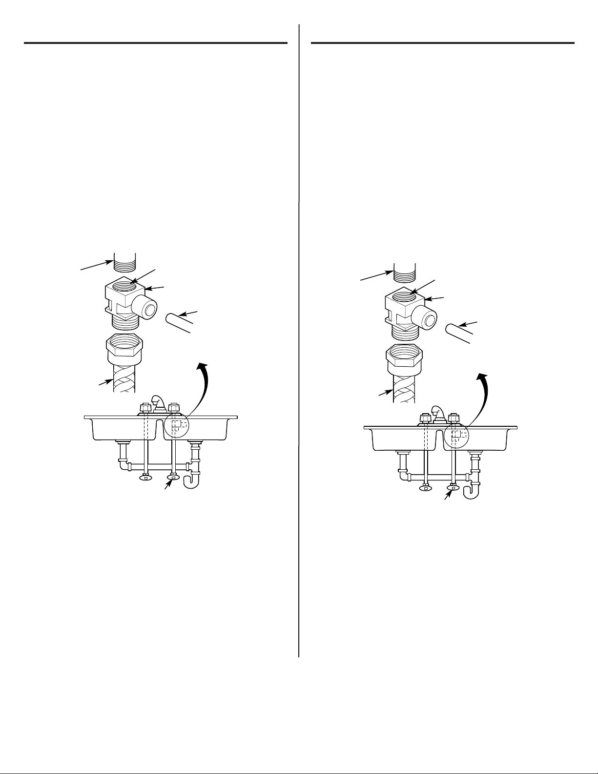
Cold Water Supply Fitting
A. PREFERRED INSTALL ATION
(Utilizing existing kitchen sink water supply valve and flexible faucet
tubing)
A typical connection using the included water supply fitting is shown
in the illustration below.
1. Close the water shut-off valve that is immediately in front of the
supply tube and open the faucets to drain water from the sink cold
water pipe.
2. Remove the nut that connects the cold water faucet to the supply
tube. Some water may spill out.
NOTES:
• Be sure to turn off the water supply and open a faucet to drain the
pipe.
• Make sure the gasket is installed in the water supply fitting.
3. Hand-tighten the water supply fitting onto the cold water faucet.
Be sure the gasket , as shown, is in place before final assembly.
Finish tightening with an adjustable wrench. Be careful not to
overtighten or cross-thread, as damage to the threads can
occur. Make sure the 1/4″ quick connection is not against a wall
that causes the supply tubing connection to bend. A quarter turn to
tighten or loosen the adapter may be necessary to avoid this.
4. Reconnect faucet tubing line to the fitting.
5. Install tubing. (See Installing the Tubing section.)
Instrucciones de instalación.
Accesorio para el suministro de agua fría
A. INSTALACIÓN PREFERIDA
(Utilizando la válvula existente de suministro de agua del lavaplatos
de la cocina y la tubería flexible del grifo)
En la ilustración que aparece a continuación se muestra una conexión
típica usando el accesorio para el suministro de agua incluido.
1. Cierre la válvula de agua que se encuentra inmediatamente en
frente del tubo de suministro y abra los grifos para dejar correr el
agua de la tubería de agua fría del lavaplatos.
2. Retire la tuerca que conecta el grifo de agua fría al tubo de
suministro. Es posible que se derrame un poco de agua.
NOTAS:
• Asegúrese de cerrar el suministro de agua y abra el grifo para
drenar la tubería.
• Asegúrese que esté instalada la junta en el accesorio de suministro
de agua.
3. Ajuste en forma manual el accesorio de suministro de agua fría en
el grifo de agua fría. Asegúrese que la junta, como se muestra, esté
en su lugar antes del ensamble final. Termine de colocar la misma
con una llave de ajuste. Asegúrese de no forzar ni presionar por
demás a fin de evitar dañar la rosca. Asegúrese que la conexión
rápida de 1/4″ no esté contra una pared que haga que la conexión
del tubo de suministro se tuerza. Es posible que se necesite
presionar o aflojar el adaptador con un cuarto de giro a fin de
evitar esto.
4. Vuelva a conectar la tubería del grifo al accesorio.
5. Instale la tubería. (Consulte la sección de Instalación de la tubería.)
8
Cold Water
Faucet Stud
Cold
Water Pipe
Water Supply Fitting
1/4″ Tubing to
Water Filter Inlet
Cold Water Shutoff
Gasket
Fig. 1
Perno del
grifo de
agua fría
Tubería de
agua fría
Accesorio de suministro de agua
Tubo de 1/4” a entrada
del filtro de agua
Válvula de cierre de agua fría
Junta
Fig. 1
Page 9

Installation Instructions.
Cold Water Supply Fitting (cont.)
B. OPTIONAL HOME INSTALLATION
(Where codes permit)—Saddle Valve: Saddle valve must be able
to connect with 1/4-inch tubing supplied with system.
Not supplied with product; check your local hardware or home
service store for product
Saddle valve typically requires 1/2″ OD tubing or larger.
NOTE: Codes in the state of Massachusetts require installation by a
licensed plumber and do not permit the use of the saddle valve. For
installation, use plumbing code 248-CMR of the Commonwealth of
Massachusetts.
1. Turn off the cold water supply and install saddle valve as required
by product selection. (Be sure to follow manufacturers’ installation
instructions.)
DANGER:
If hole is required to be drilled in pipe, to
protect yourself from serious injury or fatal shock, use a battery
powered hand drill only to make the hole. DO NOT USE AN ELECTRIC
DRILL.
2. Open saddle valve only after complete system has been installed.
C. OPTIONAL INSTALLATION
(For installation with rigid pipe between supply valve and sink faucet)
Option 1
1. Remove pipe from supply valve and sink faucet .
2.
Obtain flexible pipe sized to your plumbing.
3. Install flexible pipe.
4. Go back to A. Preferred Installation section step 3.
Option 2
1. Obtain compression fittings to fit rigid pipe.
2.
Obtain any other fittings required to connect compression fittings
to feed water adapter.
3. Remove pipe from supply valve.
4. Cut pipe to fit length of assembled fittings and adapter.
5. Install compression fitting to pipe.
6. Go back to A. Preferred Installation section step 3.
NOTE: Above described materials are not included with the product.
Faucet Spout Installations (see Fig. 2, page 10)
1. Remove spout (A) and faucet body (B) from faucet packaging.
2.
Move the threaded dome-shaped collar (C) on the spout up and away
from the o-rings on the spout.
3. Gently insert the spout into the top of the faucet body.
NOTE: Turning the spout left to right during installation will help the
o-rings to slide in easily.
4. Once the spout (A) has been installed and fully seated, slide the
threaded collar (C) down to the faucet body (B).
5. Tighten the collar by hand to the faucet body by turning in a
clockwise direction.
Instrucciones de instalación.
Accesorio para el Suministro de Agua Fría (cont.)
B. INSTALACIÓN OPCIONAL EN EL HOGAR
(Donde lo permitan los códigos)—Válvula de asiento: La válvula de
asiento debe poder conectarse con el tubo de 1/4 de pulgada
suministrado con el sistema.
No se suministra con el producto; consulte en la ferretería local o
tienda de servicios para el hogar.
La válvula de asiento típicamente requiere una tubería con un diámetro
exterior de 1/2” o superior.
NOTA: Los códigos del estado de Massachusetts exigen la
instalación por parte de un plomero con licencia y no permite el uso
de una válvula de asiento. Para la instalación, utilice el código de
plomería 248-CMR del estado de Massachusetts.
1. Cierre el suministro del agua fría e instale la válvula de asiento según
lo requiera el producto (Cerciórese de seguir las instrucciones de
instalación del fabricante).
PELIGRO: Si se necesita taladrar un agujero en la
tubería, para protegerse contra lesiones serias o choques fatales,
utilice únicamente un taladro manual operado por batería para
perforar el orificio. NO UTILICE UN TALADRO ELÉCTRICO.
2. Abra la válvula de asiento únicamente después de haber instalado
todo el sistema.
C. INSTALACIÓN OPCIONAL
(Para la instalación con una tubería rígida entre la válvula de suministro
y el grifo del lavaplatos)
Opción 1
1. Remueva la tubería de la válvula de suministro y del grifo del lavaplatos.
2.
Obtenga tubería flexible con un tamaño acorde con su tubería
de la casa.
3. Instale la tubería flexible.
4. Refiérase a A. Sección de instalación preferida en el paso 3.
Opción 2
1. Obtenga accesorios de compresión para hacer el ajuste de la
tubería rígida.
2.
Obtenga cualquier accesorio requerido para conectar el adaptador
de compresión al
adaptador para la alimentación de agua
.
3. Remueva la tubería de la válvula de suministro.
4. Corte la tubería para que se ajuste a la longitud de los accesorios
ensamblados y al adaptador.
5. Instale el accesorio de compresión a la tubería.
6. Refiérase a A. Sección de instalación preferida en el paso 3.
NOTA: Los materiales descritos anteriormente no están incluidos con
el producto.
Instalación del pico del grifo (ver Fig. 2, página 10)
1. Retire el pico (A) y pieza del grifo (B) del paquete del grifo.
2.
Mueva el collar enroscado en forma de cúpula (C) en el pico hacia arriba
y lejos de los aros tóricos en el pico.
3. Suavemente inserte el pico en la parte superior de la pieza del grifo.
NOTA: Girar el pico de la izquierda a la derecha durante la
instalación ayudará a que los aros tóricos se deslicen fácilmente.
4. Una vez que el pico (A) se haya instalado y esté completamente
acomodado, deslice el collar enroscado (C) hacia abajo en dirección
de la pieza del grifo (B).
5. Apriete el collar a mano a la pieza del grifo girando en la dirección
del reloj.
9
Page 10
Installation Instructions.
Faucet Installation
Be sure there is room underneath and above the sink to make the needed
connections. Before starting, make sure there is sufficient room for the
battery powered faucet base. Select one of the following places to install
the faucet:
1. In an existing sink spray attachment or soap dispenser hole.
2. In a hole to be drilled in the sink top.
3. In a hole to be drilled in the countertop, next to the sink.
NOTE: Be sure the faucet base will fit flat against the surface at the selected
location so the bottom gasket between the base and surface area will seal.
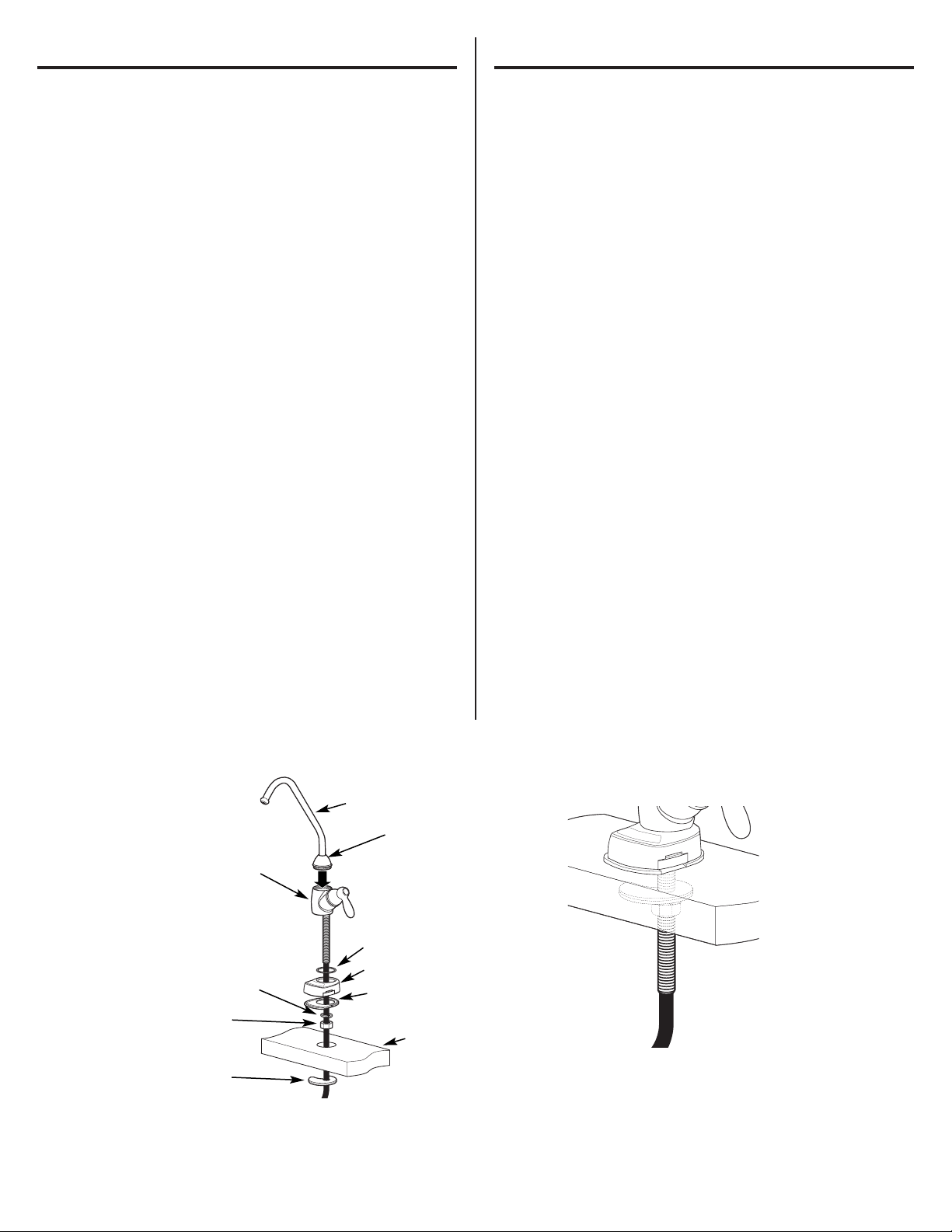
Installation Steps (refer to Fig. 2 for clarification)
1. If drilling is needed, make a 3/4″ diameter hole.
Be sure to use the proper procedure for drilling porcelain or stainless
steel. Special drill bits may be needed. Consult a qualified plumber for
the proper procedure.
2. Remove the faucet with pre-installed tubing, thin o-ring (D), faucet base
(E), bottom base gasket (F), lock washer (G), hex nut (H) and mounting
bracket (I) from the packaging.
3.
Feed tubing connected to the faucet through the thin o-ring (D), faucet
base (E), bottom base gasket (F), lock washer (G) and hex
nut (H).
4. Thread the hex nut (H) up the stem of the faucet until the height
between the bottom of the base gasket (F) and top of the lock washer
(G) is slightly larger than the thickness of the mounting surface (J).
5. Lower the faucet assembly into place in the mounting hole and
orient to final position. Place the mounting bracket (I) above the
lock washer (G) around the faucet stem (Fig. 3). While holding the
mounting bracket in place, securely tighten the hex nut.
NOTE: Two people may be required to complete this step.
Instrucciones de instalación.
Instalación del grifo
Cerciórese de que haya suficiente espacio debajo y encima del lavaplatos
para realizar la conexión necesaria. Antes de empezar, cerciórese de que
haya suficiente espacio para la base del grifo operada por batería.
Seleccione uno de los siguientes lugares para instalar el grifo:
1. En un orificio accesorio rociador existente en el lavaplatos u orificio de
dispensador de jabón.
2. En un orificio a perforar en la parte superior del lavaplatos.
3. En un orificio a perforar en el mostrador, al lado del lavaplatos.
NOTA: Cerciórese de que la base del grifo quede plana contra la superficie en
la ubicación seleccionada de manera que el empaque de abajo entre la base
y el área de la superficie quede sellado.
Pasos para la instalación (consulte la Fig. 2 para aclaración)
1. Si es necesario perforar, haga un orificio de 3/4″ de diámetro.
Cerciórese de utilizar el procedimiento correcto para perforar
porcelana o acero inoxidable. Podría necesitar brocas adicionales.
Consulte a un plomero calificado para el procedimiento correcto.
2. Retire del paquete el grifo con la tubería preinstalada, aro tórico fino (D),
base del grifo (E), empaque inferior de la base (F), arandela de seguridad
(G), tuerca hexagonal (H) y soporte de montaje (I).
3.
Inserte la tubería conectada al grifo a través del aro tórico fino (D), la
base del grifo (E), el empaque inferior de la base (F), la arandela de
seguridad (G) y la tuerca hexagonal (H).
4. Enrosque la tuerca hexagonal (H) en el vástago del grifo hasta que la
altura entre la parte inferior del empaque de la base (F) y la parte
superior de la arandela de seguridad (G) sea ligeramente más grande
que el grosor de la superficie de montaje (J).
5. Baje la ensambladura del grifo a su lugar en el orificio de montaje y
oriente hacia la posición final. Coloque el soporte de montaje (I) por
encima de la arandela de seguridad (G), alrededor del vástago del grifo
(Fig. 3). Mientras sostiene el soporte de montaje en su lugar, apriete
firmemente la tuerca hexagonal.
NOTA: Es posible que sean necesarias dos personas para completar
este paso.
(D) O-ring / Aro tórico
(F) Gasket / Empaque
(E) Faucet base / Base del grifo
(A) Spout / Pico
(G) Lock washer /
Arandela de seguridad
(H) Hex nut /
Tuerca hexagonal
(I) Mounting
bracket /
Soporte de
montaje
Fig. 2
Fig. 3
(J) Mounting surface /
Superficie de montaje
(C) Collar / Collar
(B) Faucet body /
Pieza del grifo
10
Page 11

11
Installation Instructions.
Mounting System Installation
Pick a location under the sink to mount the system. Location should be
easily accessible, with clearance between the bottom of the filter canisters
and the floor or bottom of the cabinet; any less will result in difficulty of
removing filter canisters (see Fig. 5). Allow enough space on either side of
the system for the tubing connections.
SCREW INSTALLATION
1. Remove this template from the manual for easier installation.
2. The top of the template openings should be placed a minimum of 17
inches above the bottom of the cabinet or floor where the system is to
be mounted (Fig. 4 and 5).
NOTE: Any distance lower may result in filter canisters interfering with
the floor when removed.
3. Tape template to wall, then mark the wall where the screws are to be
installed.
Install screws into the wall, leaving 3/16 inch clearance between the head
of the screw and wall (drill pilot holes if needed) (Fig. 6).
Instrucciones de instalación.
Montaje del sistema
Seleccione una ubicación debajo del lavaplatos para instalar el sistema.
La ubicación debe ser de fácil acceso, con espacio entre la base de los
cartuchos de los filtros y el piso o la base del gabinete; cualquier espacio
inferior presentará dificultades para retirar los cartuchos de los filtros
(Fig. 5). Permita suficiente espacio para cualquier lado del sistema para
las conexiones de la tubería.
INSTALACIÓN DEL TORNILLO
1. Remueva esta plantilla del manual para una instalación más fácil.
2. La parte superior de las aberturas de la plantilla deben colocarse
a un mínimo de 17 pulgadas por encima del fondo del gabinete
o del piso donde el sistema será montado (Figs. 4 y 5).
NOTA: Cualquier distancia menor podría resultar en que los cartuchos
de los filtros interfieran con el piso cuando sean removidos.
3. Pegue la plantilla a la pared con cinta adhesiva, luego marque la pared
donde los tornillos serán instalados.
Instale los tornillos en la pared, dejando un huelgo de 3/16 de pulgada
entre la cabeza del tornillo y la pared (taladre agujeros pilotos si es
necesario) (Fig. 6).
17 inches /
17 pulgadas
5 inches /
5 pulgadas
Bottom of Cabinet or Floor / Fondo del gabinete o piso
Template for screw hole pattern on back of filtration system /
Plantilla para el marco de los agujeros de los tornillos en la parte posterior del sistema de filtración
Fig. 4
17 inches /
17 pulgadas
5 inches /
5 pulgadas
Screws /
Tornillos
Screw /
Tornillo
3/16 inch /
3/16 de pulgada
Fig. 6
Fig. 5
Wall / Pared
Page 12

12
Installation Instructions.
Mounting System Installation
Mounting System to Screws Installed in Wall
1. Remove shrink wrap from filter system.
2. Hang the system on the previously installed screws using the openings
on the back of the unit (Fig. 7).
3. If the head of the screw will not slide into the upper slot, back out the
screw by 1/4 turn and try again.
4. If the system is too loose when placed on the wall, tighten the screws
by 1/4 turn and try again until a desired fit is achieved.
Instrucciones de instalación.
Montaje del sistema
Montaje del sistema a los tornillos instalados en la pared
1. Remueva la envoltura de pliegue del sistema del filtro.
2. Cuelgue el sistema en los tornillos previamente instalados usando las
aberturas en la parte posterior de la unidad (Fig. 7).
3. Si la cabeza de los tornillos no se deslizan en las ranuras superiores,
destornille 1/4 de vuelta y trate de nuevo.
4. Si el sistema está demasiado flojo cuando sea colocado en la pared,
apriete los tornillos 1/4 de vuelta y trate de nuevo hasta que el ajuste
apropiado sea logrado.
Min.
17 inches /
17 pulgadas
5 inches /
5 pulgadas
Fig. 7
Page 13
Installation Instructions.
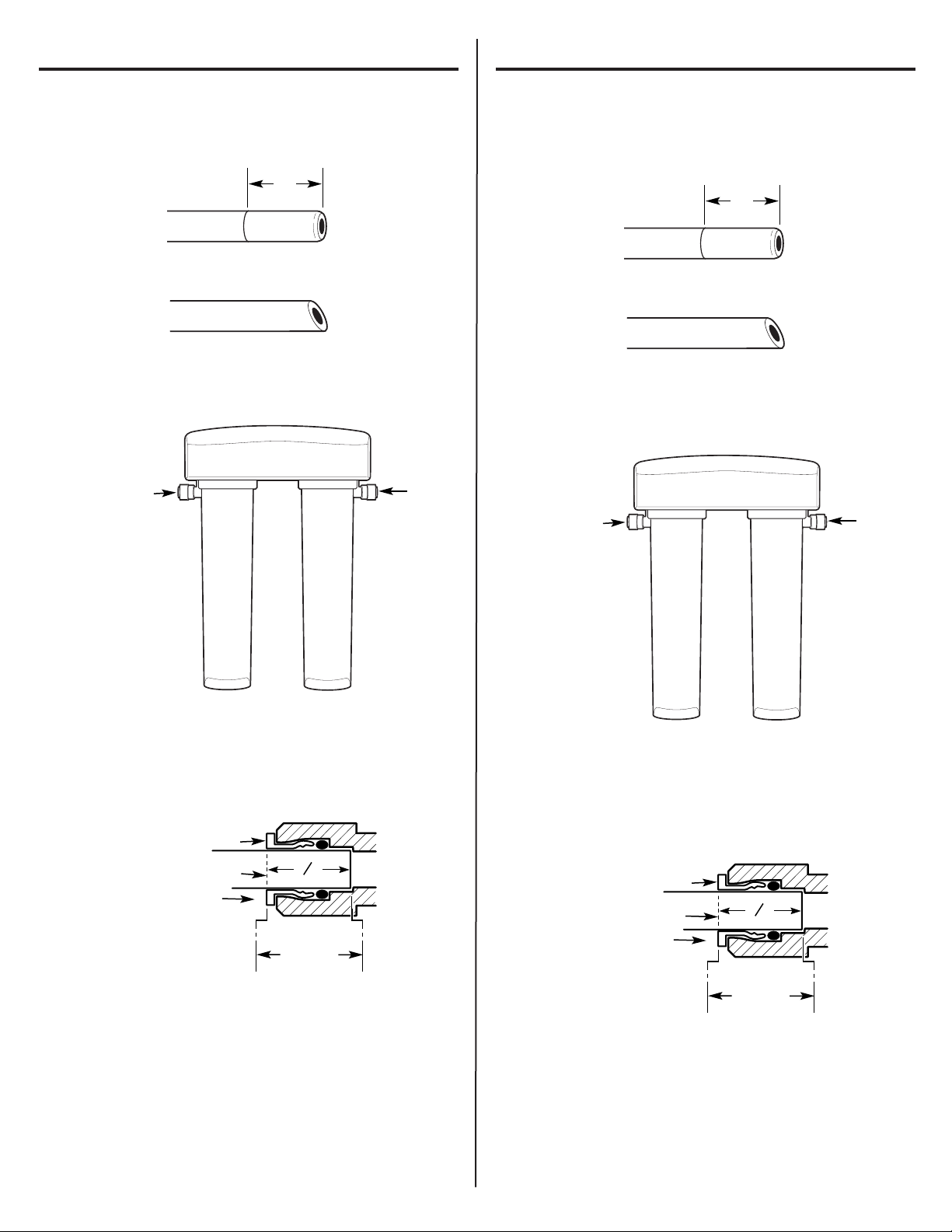
Installing the Tubing
1. Measure 3/4″ from the end of each remaining piece of tubing (faucet
end and inlet end) and mark with a pencil (Fig. 8). (Check for roundness,
smoothness, cuts, nicks, flat spots and sharp edges.)
2. NOTE: Water flow is from left to right . Water inlet is on the left side
and water outlet is on the right side. Failure to follow will result in
water leaks when filter canisters are removed.
3 Push the tubing firmly into each fitting on the manifold until the line is
flush with the fitting collar. (If the tubing is removed, re-cut the end,
measure, mark and re-insert). Tubing must be fully inserted to avoid
leaks (Fig. 9). (To remove tubing, depress and hold white collet; pull
tubing out to remove.)
4 Pull out slightly on tubing to ensure a good seal.
5. Install the other end of the tubing from the inlet side of the manifold to
the feed water adapter.
NOTE: Inspect the ends of the tubing to be sure there are no
imperfections and that the end of the tubing is cut square. It may be
necessary to cut the tubing again.
Instrucciones de instalación.
Cómo instalar la tubería
1. Mida una distancia de 3/4 pulgada desde el extremo de cada pieza
restante de tubería (extremo del grifo y extremo de la entrada) y marque
con lápiz (Fig. 8). (Revise que quede pareja, lisa y que no tenga cortes,
hendiduras, puntos planos o bordes filosos).
2. NOTA: El flujo de agua es de izquierda a derecha. La entrada del agua
está en el lado izquierdo y la salida en el lado derecho. No seguir
estas instrucciones podría resultar en fugas cuando los cartuchos de
los filtros sean removidos.
3 Empuje la tubería firmemente hacia cada conexión en el recolector
hasta que la tubería esté nivelado con el collar. (Si se retira la tubería,
vuelva a cortar el extremo, mida, marque y vuelva a insertar). La tubería
debe estar firmemente insertada para evitar fugas (Fig. 9). (Para retirar
la tubería: Libere y sostenga la boquilla blanca; hale la tubería hacia
fuera para retirar.)
4 Saque la tubería ligeramente para asegurar un buen sellamiento.
5. Instale el otro extremo de la tubería desde el lado de la entrada del
recolector al adaptador de suministro de agua.
NOTA: Inspeccione los extremos del tubo para asegurarse que no
haya imperfecciones y que el extremo de la tubería se haya cortado
perpendicularmente. Es posible que se necesite volver a cortar
la tubería.
3/4″
(19 mm)
Fig. 8
INCORRECT
Inlet from supply valve
Outlet
to faucet
3/4″
(19 mm)
Fig. 8
INCORRECTO
Engagement
3/4″ (3/8″ tubing)
White Collet
(DO NOT REMOVE)
Insertion line
Insert tubing
Fig. 9
Entrada de la válvula
de suministro
Salida hacia
el grifo
Enganche
3/4″
(tubería de 3/8″)
Boquilla blanca
(NO RETIRAR)
Línea de inserción
Insertar tubería
Fig. 9
13
3
"
4
3
"
4
Page 14

14
Installation Instructions.
Battery Installation
1. Use a small flat blade screwdriver or coin to remove the battery tray (A)
at the side of the faucet base.
2. Install one CR2032, 3 volt battery (B) + side down into the battery tray
(A) (Fig. 10).
3. Slide tray into faucet base (C) until the battery tray (A) edge is flush with
the side of the base.
4. The blue light (D) will flash 5 times, indicating a proper installation and
system reset.
5. Normally the light is off. After 6 months of use, the light will flash again
every 30 seconds, indicating the proper time to replace the filter
canister.
NOTE: The blue light may stop blinking if it is allowed to blink for an
extended period of time. To ensure proper operation, the battery should be
replaced with every filter change.
Instrucciones de instalación.
Instalación de la batería
1. Use un destornillador de pala plana pequeño o una moneda para
retirar la bandeja de la batería (A) en el costado de la base del grifo.
2. Instale una batería CR2032 de 3 voltios (B) con el lado positivo hacia
abajo en la bandeja (A) (Fig. 10).
3. Deslice la bandeja en la base del grifo (C) hasta que el borde de la
bandeja de la batería (A) esté nivelado con el costado de la base.
4. La luz azul (D) se iluminará de manera intermitente 5 veces, indicando
una instalación correcta y la reinicialización del sistema.
5. Normalmente la luz está apagada. Después de 6 meses de uso,
la luz se encenderá de manera intermitente nuevamente cada 30
segundos, indicando que es el momento de reemplazar el filtro.
NOTA: La luz azul puede dejar de encenderse si se deja por un periodo de
tiempo prolongado. Para verificar la operación correcta, se debe cambiar la
batería con cada cambio de filtro.
Fig. 10
+
–
(B) Battery / Batería
(C) Faucet base /
Base del grifo
(A) Battery tray / Bandeja de la batería
(D) Blue light / Luz azul
Page 15
Flush Procedure
Whenever water of unknown quality is passed through the GE Water
Filtration system, the filter canisters should be discarded and the filtration
system flushed.
WARNING: These systems should only be used on
microbiologically safe water.
Circumstances that may require flushing the system are:
• Boil water advisory
• Flooding of the GE Water Filtration system
• Long-term non-use
The procedure for flushing the GE Water Filtration system is:
1. See Replacing the Filter Canisters section and follow steps 1–4.
Procedimiento para lavar
Cada vez que agua de calidad desconocida es pasada a través del
sistema de filtración de agua GE, los cartuchos de los filtros deberían
ser deshechados y el sistema de filtración lavado.
ADVERTENCIA: Estos sistemas solamente deberían usarse
en agua microbiológicamente segura.
Las circunstancias que podrían requerir el lavado del sistema son:
• Advertencia de que hay que hervir el agua
• Inundación del sistema de filtración de agua GE
• Largo tiempo sin ser usado
El procedimiento para lavar el sistema de filtración de agua GE es:
1. Vea la sección Cómo reemplazar los cartuchos de los filtros y siga los
pasos 1–4.
Installation Instructions.
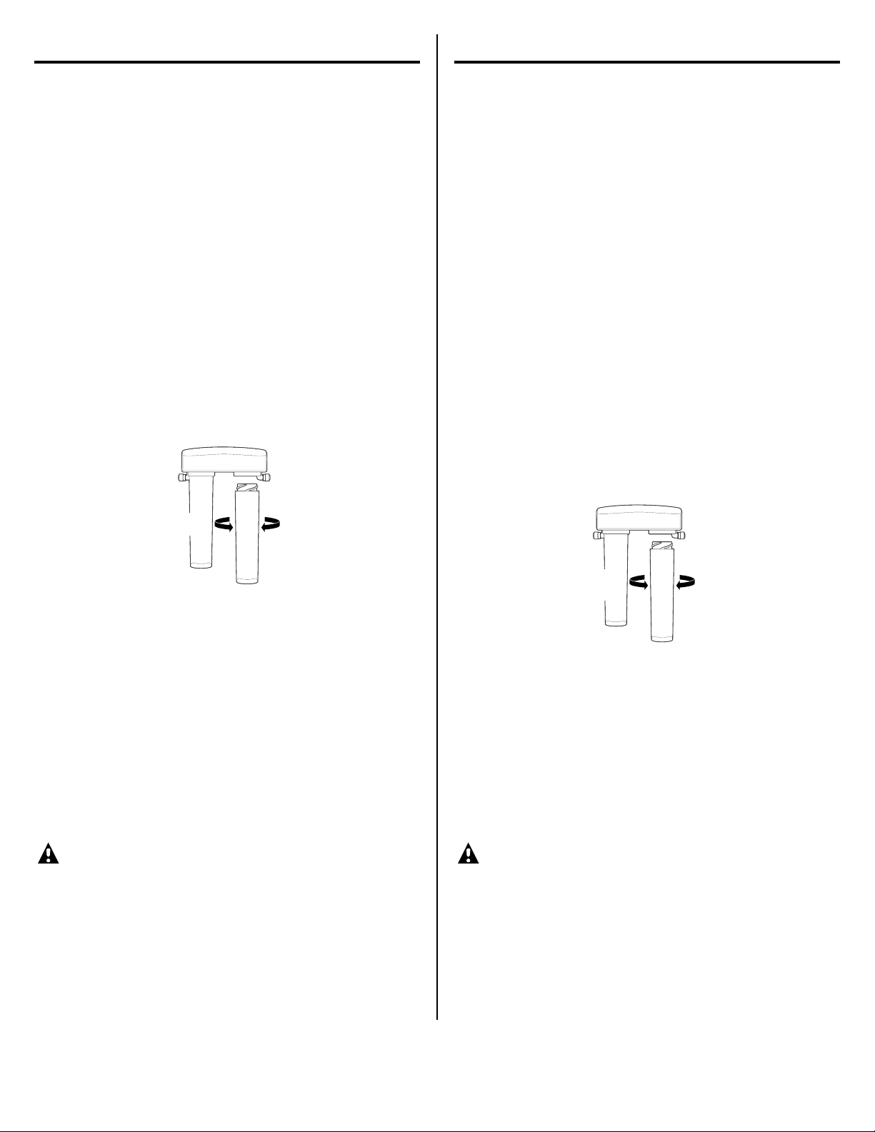
Replacing the Filter Canisters
The blue light in the faucet base will flash every 30 seconds to indicate a
filter change is needed. This occurs every 6 months.
1. Remove the filter canisters from the manifold by rotating the canisters
to the left about 1/3 turn (Fig. 11). NOTE: A small amount of water from
the tubing between the filter and the faucet may come out. A small towel
should be able to catch it.
2. Remove foil on top of new replacement filter canisters. Install the new
canisters into the manifold by turning to the right about 1/3 turn until
the alignment marks line up and the filter stops. DO NOT
OVERTIGHTEN. The filter will rise up as it is turned.
3. Turn handle on faucet to allow trapped air to purge from the system.
NOTE: System may make noise during this procedure.
4. Check for water leaks around the system.
5. Once water starts to flow out of the faucet, allow the system to run for
5 minutes to flush out any harmless carbon fines that may be present.
6. Turn off faucet and check around system for leaks.
7. Remove battery tray and replace battery to reset timer. (See Battery
Installation for proper procedure).
Instrucciones de instalación.
Cómo reemplazar los cartuchos de los filtros
La luz azul en la base del grifo se encenderá de forma intermitente cada
30 segundos para indicar que es necesario cambiar el filtro. Esto ocurre
cada 6 meses.
1. Retire los cartuchos de los filtros del recolector girando los cartuchos
hacia la izquierda 1/3 de giro. (Fig. 11). NOTA: Podría salir una pequeña
cantidad de agua de la tubería entre el filtro y el grifo, la cual se puede
absorber con una toalla pequeña.
2. Retire el aluminio de la parte superior de los cartuchos de repuestos. Instale
los nuevos cartuchos en el recolector girándolos hacia la derecha alrededor
de 1/3 de giro hasta que las marcas de alineación queden en línea y el filtro
pare. NO APRIETE EN EXCESO. El filtro podría levantarse a medida que
se gira.
3. Gire la manija en el grifo para permitir que el aire atrapado se purgue
del sistema.
NOTA: Es posible que el sistema haga ruido durante este procedimiento.
4. Busque fugas de agua alrededor del sistema.
5. Una vez que el agua empiece a fluir del grifo, deje que el sistema opere
por 5 minutos para expulsar cualquier traza de carbono que pueda
estar presente.
6. Cierre el grifo y revise alrededor del sistema en busca de fugas.
7. Retire la bandeja de la batería y vuelva a instalar la batería para
inicializar el temporizador. (Vea la instalación de la batería para
el procedimiento correcto).
Replacement Filter Canisters/Estimated Replacement Costs
FQSLF—Replacement filter canister $30–35
FQSVF—Replacement filter canister $35–40
For replacement parts, call toll-free 800.626.2002.
Repuestos de los cartuchos del filtros/Costos estimados de reposición
FQSLF—Repuesto del cartucho del filtro $30–35
FQVSF—Repuesto del cartucho del filtro $35–40
Para repuestos, llame gratis al 800.626.2002 (EE.UU.).
15
To install
To remove
Fig. 11
Para
instalar
Para
retirar
Fig. 11
Page 16

16
Before you call for service…
Problem Possible Causes What To Do
Water contains tiny New filter canisters contain • Turn on the filtered water faucet and allow these harmless carbon
black particles activated carbon, which is a particles to purge from the canisters. Turn off the faucet when the
harmless black powder. water is clear.
Water has air bubbles Air in system after installation. • Will go away after water runs for a while.
and is cloudy
Indicator light on the Six months usage has occurred. • Replace both filter canisters and battery in the faucet base.
faucet base is flashing This is the maximum life of
the filter canisters.
Indicator light on the Normal operation. • Does not blink until 6 months of operation has passed.
faucet base is not blinking
Battery may need to be replaced. • Normally the light is not on. The light blinks every 30 seconds to
indicate a filter change is needed. This occurs about every 6 months.
• Replace battery. Indicator light will blink rapidly 5 times to indicate
proper installation and operation.
Indicator light on the Battery may need to be • Observe orientation markings on the holder and install correctly.
faucet base is not
replaced or it may have been Replace battery if it is old.
working
when new installed incorrectly.
battery is installed
Chlorine taste and/or The filter canisters are no •
Replace the filter canisters.
odor in the product water longer removing chlorine
from the water supply.
Water dispenses The filters have been installed • A six-month change-out period is recommended. Replace both
very slowly
for too long. filter canisters.
The filter canisters have • High sediment levels can cause premature clogging. Replace both
become clogged. filter canisters.
Fittings are leaking Tubing may not be installed • Fully follow the installation instructions and be sure the tubing is
properly. free of nicks, burrs, etc., and is installed to the proper depth.
No water dispensing Filter canisters not fully installed. • Fully follow the filter replacement instructions.
from system
Troubleshooting Tips
Save time and money! Review the chart
below first and you may not need to call
for service.
Page 17

17
Antes de solicitar un servicio…
Problema Posibles causas Qué hacer
El agua contiene Los nuevos cartuchos de los filtros • Abra el grifo de agua filtrada y permita que estas partículas inofensivas
pequeñas partículas contienen carbono activado, el cual de carbono se purguen de los cartuchos. Cierre el grifo cuando el agua
negras es un polvo negro inofensivo. salga limpia.
El agua tiene burbujas Hay aire en el sistema después •Desaparecerá después de que el agua corra por un tiempo.
de aire y está turbia de la instalación.
La luz indicadora Han transcurrido seis meses • Reemplace los cartuchos de los filtros y la batería en la base
en la base del grifo de uso. Esta es la vida máxima del grifo.
está intermitente de los cartuchos de los filtros.
La luz indicadora Esto es normal. • No parpadea hasta que 6 meses de operación han transcurrido.
en la base del grifo
Es posible que la batería • Normalmente la luz no está encendida. La luz se enciende de manera
no está intermitente.
necesite reemplazo. intermitente para indicar que es necesario cambiar el filtro. Esto
ocurre cada seis meses.
• Reemplace la batería. La luz indicadora se encenderá rapidamente
5 veces para indicar la instalación y operación correcta.
La luz indicadora La batería podría necesitar •Observe las marcas de orientación en el receptáculo e instale
en la base del grifo
reemplazo o podría haberse correctamente. Reemplace la batería si está vieja.
no funciona cuando se
instalado incorrectamente.
instala una nueva batería
Olor y/o sabor a cloro Los cartuchos de los filtros ya •
Reemplace los cartuchos de los filtros.
en el agua producida no están retirando el cloro del
suministro de agua.
El agua se dispensa El filtro ha estado instalado • Se recomienda un periodo de cambio de seis meses. Reemplace
muy lentamente
por mucho tiempo. los cartuchos de los filtros.
Los cartuchos de los filtros • Altos niveles de sedimento pueden causar una obstrucción
están obstruidos. prematura. Reemplace los cartuchos de los filtros.
Los accesorios Es posible que la tubería • Siga las instrucciones de instalación en su totalidad y asegúrese
tienen fugas no esté instalada correctamente. que la tubería no posea rasguños, rebabas, etc. y que esté
instalada a una profundidad adecuada.
No sale agua Los cartuchos de los filtros no • Siga completamente las instrucciones para reemplazo.
del sistema
están instalados completamentes.
Solucionar problemas
¡Ahorre tiempo y dinero! Revise la siguiente tabla primero
y tal vez no necesitará de solicitar un servicio.
Page 18

Notes. / Notas.
18
Page 19

19
Soporte al consumidor.
Página Web de GE
www.GEAppliances.com
¿Tiene alguna pregunta sobre su electrodoméstico? ¡Pruebe la página Web de GE 24 horas al día, cualquier día del año! Para mayor
conveniencia y servicio más rápido, ya puede descargar los Manuales de los Propietarios o pedir piezas en línea.
Solicite una reparación www.GEAppliances.com
El servicio de expertos GE está a tan sólo un paso de su puerta. Llame al 800.GE.CARES (800.432.2737) durante horas normales
de oficina para solicitar su reparación.
Real Life Design Studio (Estudio de diseño para la vida real)
www.GEAppliances.com
GE apoya el concepto de Diseño Universal—productos, servicios y ambientes que pueden usar gente de todas las edades, tamaños
y capacidades. Reconocemos la necesidad de diseñar para una gran gama de habilidades y dificultades físicas y mentales. Para más
detalles cobre las aplicaciones de GE Diseño Universal, incluyendo ideas de diseño para la cocina para personas con discapacidades, mire
nuestra página Web hoy mismo. Para personas con dificultades auditivas, favor de llamar al 800.TDD.GEAC (800.833.4322).
Garantías ampliadas www.GEAppliances.com
Compre una garantía ampliada y obtenga detalles sobre descuentos especiales disponibles mientras su garantía está aún activa. Puede
comprarla en línea en cualquier momento, o llamar al (800.626.2224) durante horas normales de oficina. GE Consumer Home Services
estará aún ahí cuando su garantía termine.
Piezas y accesorios www.GEAppliances.com
Aquellos individuos con la calificación necesaria para reparar sus propios electrodomésticos pueden pedir que se les manden
las piezas o accesorios directamente a sus hogares (aceptamos las tarjetas VISA, MasterCard y Discover). Haga su pedido en línea hoy,
24 horas cada día o llamar por teléfono al 800.626.2002 durante horas normales de oficina.
Las instrucciones descritas en este manual cubren los procedimientos a seguir por cualquier usuario. Cualquier otra reparación debería, por regla general,
referirse a personal calificado autorizado. Debe ejercerse precaución ya que las reparaciones incorrectas pueden causar condiciones de funcionamiento
inseguras.
Póngase en contacto con nosotros www.GEAppliances.com
Si no está satisfecho con el servicio que recibe de GE, póngase en contacto con nosotros en nuestra página Web indicando todos los
detalles así como su número de teléfono o escríbanos a: General Manager, Customer Relations
GE Appliances, Appliance Park
Louisville, KY 40225
Registre su electrodoméstico www.GEAppliances.com
¡Registre su nuevo electrodoméstico en línea—cuando usted prefiera! El registrar su producto a tiempo le proporcionará, si surgiera la
necesidad, una mejor comunicación y un servicio más rápido bajo los términos de su garantía. También puede enviar su tarjeta
de registro pre-impresa que se incluye en el material de embalaje.
Impreso en Estados Unidos
GARANTÍA LIMITADA POR UN AÑO
• ¿Qué cubre esta garantía?
— Cualquier defecto de fábrica en los materiales o la manufactura del producto.
• ¿Qué no cubre esta garantía?
—
Cartucho de los filtros y las baterías después de treinta días a partir de la fecha de la compra.
— Viajes a su casa para enseñarle cómo usar el producto.
— Instalación o entrega inapropiada, o mantenimiento impropio.
— Falla del producto debido a abuso, mal uso, alteración, uso comercial o uso diferente al
propósito deseado con este producto.
— Uso de este producto donde el agua está microbiológicamente insegura o de calidad
desconocida, sin la adecuada desinfección, antes y después de ser procesada por el
sistema. Los sistemas certificados para reducir el nivel de quistes pueden ser usados
en agua desinfectada que pueda contener quistes que se puedan filtrar.
— Daños causados al producto debido a accidentes, incendio, inundaciones o actos
de la naturaleza.
— Daños secundarios o por consecuencia causados por posibles defect
os en el
pr
oduct
o, su instalación o reparación.
• ¿Por cuánto tiempo después de la compra?
— Un año.
• ¿Cómo hago la reclamación de la garantía?
—
Devuélvala al minorista a quien le compró el producto con una copia de “Proof of
Purchase”(prueba de compra). Se le proporcionará una unidad nueva o reacondicionada. Esta
garantía excluye los costos de envío o llamadas de servicio a domicilio.
Esta garantía se extiende al comprador original y cualquier comprador
posterior de productos comprados para uso residencial o en la oficina dentro de
Estados Unidos. En Alaska, la garantía excluye el costo de envío o las visitas de
servicio a su casa u oficina.
Algunos estados no permiten la exclusión o las limitaciones de daños
incidentales o consecuenciales. Esta garantía da derechos legales específicos, y
usted podría tener otros derechos que variarán de estado a estado. Para saber
cuáles son sus derechos legales, consulte a la oficina de asuntos del
consumidor local o la oficina del Attorney General en su localidad.
Póngase en contacto con nosotros en ge.com, o llame sin cargo al 800.952.5039.
Garantía del sistema de filtración de agua GE.
EXCLUSIÓN DE GARANTÍAS IMPLÍCITAS—Su único y exclusivo derecho es el
cambio del producto, tal y como se indica en esta Garantía limitada.
Cualquier garantía implícita, incluyendo las garantías implícitas de
comerciabilidad o adecuación para un fin determinado, están limitadas a
un año o el período de tiempo más breve permitido por la ley.
Page 20

Consumer Support.
GE Appliances Website
ge.com
Have a question or need assistance with your appliance? Try the GE Appliances Website 24 hours a day, any day of the year!
For greater convenience and faster service, you can now download Owner’s Manuals or order parts on-line.
Schedule Service ge.com
Expert GE repair service is only one step away from your door. Schedule your service at your convenience by calling 800.GE.CARES
(800.432.2737) during normal business hours.
Real Life Design Studio ge.com
GE supports the Universal Design concept—products, services and environments that can be used by people of all ages, sizes
and capabilities. We recognize the need to design for a wide range of physical and mental abilities and impairments. For details
of GE’s Universal Design applications, including kitchen design ideas for people with disabilities, check out our Website today.
For the hearing impaired, please call 800.TDD.GEAC (800.833.4322).
Extended Warranties ge.com
Purchase a GE extended warranty and learn about special discounts that are available while your warranty is still in effect. You can
purchase it on-line anytime, or call 800.626.2224 during normal business hours. GE Consumer Home Services will still be there after your
warranty expires.
Parts and Accessories ge.com
Individuals qualified to service their own appliances can have parts or accessories sent directly to their homes (VISA, MasterCard and
Discover cards are accepted). Order on-line today, 24 hours every day or by phone at 800.626.2002 during normal business hours.
Instructions contained in this manual cover procedures to be performed by any user. Other servicing generally should be referred to
qualified service personnel. Caution must be exercised, since improper servicing may cause unsafe operation.
Contact Us ge.com
If you are not satisfied with the service you receive from GE, contact us on our Website with all the details including your phone number, or
write to: General Manager, Customer Relations
GE Appliances, Appliance Park
Louisville, KY 40225
Register Your Appliance ge.com
Register your new appliance on-line—at your convenience! Timely product registration will allow for enhanced communication and
prompt service under the terms of your warranty, should the need arise. You may also mail in the preprinted registration card included in
the packing material.
LIMITED ONE-YEAR WARRANTY
• What does this warranty cover?
— Any defect in materials or workmanship in the manufactured product.
• What does this warranty not cover?
— Filter canisters and batteries after 30 days from date of purchase.
— Service trips to your home to teach you how to use the product.
— Improper installation, delivery or maintenance.
— Failure of the product if it is abused, misused, altered, used commercially or
used for other than the intended purpose.
— Use of this product where water is microbiologically unsafe or of unknown
quality, without adequate disinfection before or after the system. Systems
certified for cyst reduction may be used on disinfected water that may
contain filterable cysts.
— Damage to the product caused by accident, fire, floods or acts of God.
— Incidental or consequential damage caused by possible defects with this
appliance, its installation or repair.
• For how long after the original purchase?
— One (1) year.
• How do I make a warranty claim?
— Return to the retailer from which it was purchased, along with a copy of the
“Proof of Purchase.” A new or reconditioned unit will be provided. This
warranty excludes the cost of shipping or service calls to your home.
This warranty is extended to the original purchaser and any succeeding owner
for products purchased for home or office use within the USA. In Alaska, the
warranty excludes the cost of shipping or service to your home or office.
Some states do not allow the exclusion or limitation of incidental or consequential
damages. This warranty gives you specific legal rights, and you may also have other
rights, which vary from state to state. To know what your legal rights are, consult
your local or state consumer affairs office or your state’s Attorney General.
Contact us at ge.com, or call toll-free at 800.952.5039.
GE Water Filtration System Warranty.
EXCLUSION OF IMPLIED WARRANTIES—Your sole and exclusive remedy is
product exchange as provided in this Limited Warranty. Any implied
warranties, including the implied warranties of merchantability or fitness
for a particular purpose, are limited to one year or the shortest period
allowed by law.
Printed in the United States
 Loading...