

Page 1
Safety Information ............. 2
Specifications
and Performance Claims ........ 3
About the Softener ............ 4
Before you Start ............... 7
Installation Requirements ....... 8
Installation Instructions .........11
Programming the Softener ......18
SYSTEM
Care and Cleaning ............ 25
Routine Maintenance .......... 27
Before you call for Service ..... 28
Exploded View/Parts List ...... 34
Warranty (U.S.) ............... 38
Warranty (Canada) ........... 39
Consumer Support ............42
Systems tested and certified by NSF International
against NSF/ANSI Standard 44 for the chemical
reduction claims specified on page 3, and certified
to NSF/ANSI 372.
OWNER’S MANUAL
AND INSTALLATION
INSTRUCTIONS
Model GXSHC40N
Write the model and
serial numbers here:
Model #
Serial # _____________
To find these numbers,
lift the cover and look
on the rim below the
control panel.
_____________
Systems Tested and Certified by the Water Quality
Association against CSA B483.1.
If you have any questions or concerns when installing or maintaining
your water softener, call our toll free number at 800-952-5039 (US)
or 866-777-7627 (Canada), or visit geappliances.com. When you call,
please be prepared to provide the model and serial number of your
product. This information can be found on the rating decal located on
the rim under the salt cover.
WATER SOFTENING
GE is a trademark of the General Electric Company. Manufactured under trademark license.
7375781 49-6000221 Rev. 0 04-19 GEA
Page 2
IMPORTANT SAFETY INFORMATION.
READ ALL INSTRUCTIONS BEFORE USING
SAFETY PRECAUTIONS
WARNING
For your safety, the information in this manual must be followed to
minimize the risk of electric shock, property damage or personal injury.
WARNING
galvanized cold water pipe may be used to
ground electrical outlets in the home. Failure to
maintain this ground path may result in an
electric shock hazard. If the cold water pipe is
used to ground electric outlets, please refer to
Installing the Ground Wire section before
cutting the pipe.
Check and comply with your state and local
codes. You must follow these guidelines.
Use care when handling the water softening
system. Do not turn upside down, drop, drag
or set on sharp protrusions.
Water softening systems using sodium
chloride (salt) for recharge add sodium to the
water.
Persons on sodium restricted diets should
consider the added sodium as part of their
overall intake. Potassium chloride can be
used as an alternative to sodium chloride in
your softener.
Use only lead-free solder and flux for all
sweat-solder connections, as required by
state and federal codes.
This water softening system must be properly
installed and located in accordance with the
installation instructions before it is used.
Keep the salt hole cover in place on the
softener unless servicing the unit or refilling
with salt.
A copper or
WARNING
water that is microbiologically unsafe or of
unknown quality without adequate disinfection
before or after the system.
Do not use with
WARNING
parts and packaging material after installation.
Small parts remaining after the installation
could be a choke hazard.
The water softening system works on 24 volt-
Avoid installing in direct sunlight. Excessive
If installing the water softener outdoors, do
electrical power only. Be sure to use
60 Hz
the included external power supply.
External power supply must be plugged into
an indoor 120 volt, grounded outlet only.
Use clean water softening salts only, at least
99.5% pure. NUGGET, PELLET or coarse
SOLAR salts are recommended. Do not use
rock, block, granulated or ice cream making
salts. These types of salts may contain dirt
and sediments that might mush or cake,
creating maintenance issues for the water
softener.
heat may cause distortion or other damage
to non-metallic parts.
not locate where it will be exposed to wet
weather, direct sunlight, extreme hot or cold
temperatures, or other forms of abuse.
Discard all unused
In the state of California: You must turn
the Salt Efficiency Feature setting to ON.
This may initiate more frequent recharges.
However it will operate at 4,000 grains per
pound of salt or higher. To turn on the Salt
Efficiency Feature, follow the instructions in
the “Salt Saver” section of this manual
READ AND SAVE THESE INSTRUCTIONS
In the Commonwealth of Massachusetts,
Plumbing Code 248 CMR shall be adhered
to. Consult with your licensed plumber.
2
Page 3
Specifications and Performance Claims
This model is efficiency rated. The efficiency rating is valid only at the minimum stated salt dose. The softener has
a demand initiated regeneration (D.I.R) feature that complies with specific performance specifications intended to
minimize the amount of regenerant brine and water used in its operation.
The softener has a rated salt efficiency of not less than 4,000 grains of total hardness exchange per pound of
salt (based on sodium chloride), and shall not deliver more salt than its listed rating or be operated at a sustained
maximum service flow rate greater than its listed rating. This softener has been proven to deliver soft water for at
least ten continuous minutes at the rated service flow rate. The rated salt efficiency is measured by laboratory test
described in NSF/ANSI Standard 44. These tests represent the maximum possible efficiency that the system can
achieve. Operational efficiency is the actual efficiency after the system has been installed. It is typically less than the
efficiency, due to individual application factors including water hardness, water usage, and other contaminants that
reduce the softener’s capacity.
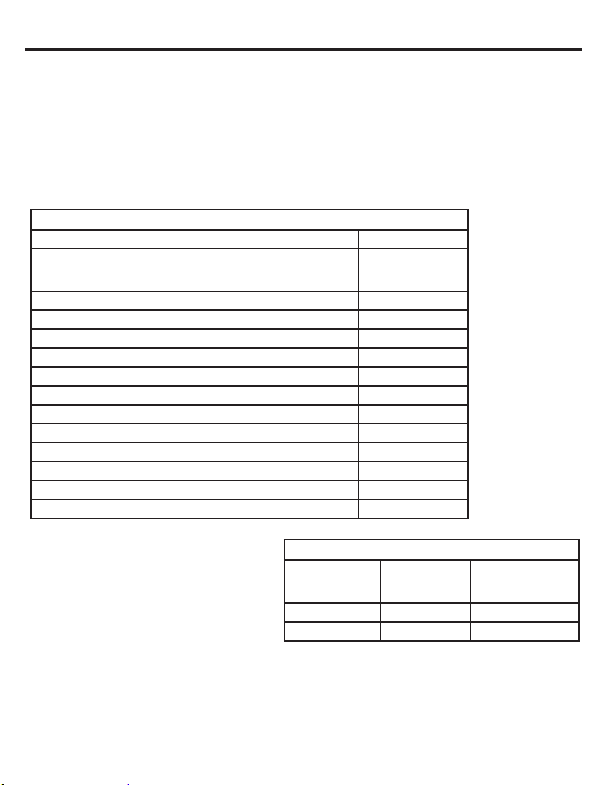
Specifications
Model GXSHC40N
Rated Capacity* (Grains@ Salt Dose) 11,700 @ 2.3 lbs
Rated Efficiency** (Grains/Pound of Salt @ Minimum Salt Dose) 5,090 @ 2.3 lbs.
Water used during Regeneration (gallons/grains) 2.7 /1000
Total Water Used per Regeneration @ Maximum Salt Dose 37.0 gallons
Amount of High Capacity Ion Exchange Resin (lb/cu.ft.) 57.56/1.11
Resin Tank Nominal Size (in., dia. x height) 9 x 40
Service Flow Rate (gpm) 9.5
Pressure Drop at Rated Service Flow (psig) 12.7
Water Supply Maximum Hardness (gpg) 110
Water Supply Maximum Clear Water Iron (ppm)*** 8
Water Pressure Limits (minimum-maximum psi)**** 20-125
Water Temperature Limits (minimum-max. °F) 40-120
Maximum Flow Rate to Drain (gpm) 2.3
31,500 @ 8.7 lbs.
40,000 @ 15.1 lbs.
These systems conform to NSF/ANSI 44 for
the specific capacity claims as verified and
substantiated by test data.
* Testing was performed using pellet grade
sodium chloride as
the regenerant salt.
** Efficiency rating is valid only at the lowest
stated salt dosage. These softeners were
efficiency rated according to NSF/ANSI 44.
*** Extent of iron removal may vary with
conditions. The capacity to reduce clear
water iron is substantiated by WQA test data.
State of Wisconsin requires additional treatment if water supply contains greater than 5 ppm clear water iron.
Refer to Cleaning Iron Out of the Water Softening System section.
**** Canada working pressure limits: 1.4–7.0 kg/cm
Contaminant
Barium 10 ±10% mg/L 2.0 mg/L
Radium 226/228 25 pCi/L 5pCi/L
Test parameters include: pH = 7.5±0.5, flow rate = 7.5 gpm
and dynamic pressure = 35±5 psig
2
.
Performance Claims
Influent
Challenge
Level
Allowable Product
Maximum
Water Level
3
Page 4

About the water softener system
SERVICE
When the water softening system is providing
soft water, it is called “Service.” During service,
hard water flows from the house main water
pipe into the water softening system. Inside the
water softening system resin tank is a bed made
up of thousands of tiny, plastic resin beads. As
hard water passes through the bed, each bead
attracts and holds the hard minerals. This is
called ion-exchanging. It is much like a magnet
attracting and holding metals. Water without
hard minerals (soft water) flows from the water
softening system and to the house pipes.
AUTOMATIC HARD WATER BYPASS DURING RECHARGE
During recharge the water softener is
automatically put in bypass mode allowing hard
water to be available to the home. Once the
softener is recharged water is directed back
through the softener to be conditioned.
After a period of time, the resin beads become
coated with hard minerals and they have to
be cleaned. This cleaning is called recharge.
Recharge is started at 2:00 AM (factory setting)
by the water softening system control, and
consists of five stages or cycles. These are
FILL, BRINING, BRINE RINSE, BACKWASH
and FAST RINSE.
However, you should avoid using HOT water
because the water heater will fill with the
hard water.
FILL
Salt dissolved in water is called brine. Brine is
needed to clean the hard minerals from resin
beads. To make the brine, water flows into the
salt storage area during the fill stage.
BRINING
During brining, brine travels from the salt
storage area into the resin tank. Brine is the
cleaning agent needed to remove hard minerals
from the resin beads. The hard minerals and
brine are discharged to the drain.
The nozzle and venturi create a suction to
move the brine, maintaining a very slow rate to
get the best resin cleaning with the least salt.
BRINE RINSE
After a pre-measured amount of brine is used,
the brine valve closes. Water continues to flow
in the same path as during brining, except for
the discontinued brine flow. Hard minerals and
brine flush from the resin tank to the drain.
BACKWASH
During backwash, water travels up through
the resin tank at a fast flow rate, flushing
accumulated iron, dirt and sediments from the
resin bed and to the drain.
FAST RINSE
Backwash is followed by a fast flow of water
down through the resin tank. The fast flow
flushes brine from the bottom of the tank, and
packs the resin bed.
After fast rinse, the water softening system
returns to soft water service.
4
Page 5

About the water softener system
NORMAL OPERATION, CONTROL DISPLAYS
During normal operation, the present time of
day and AM or PM and DAYS TO EMPTY
show in the control display area.
FEATURE: OPTIONAL RECHARGE CONTROLS
Sometimes, a manually started recharge may
be desired or needed. Two examples:
You have used more water than usual
(house guests, extra washing, etc.) and you
may run out of soft water before the next
recharge.
The system ran out of salt.
Use one of the following features to start a
recharge immediately, or at the next preset
recharge start time.
FEATURE: MEMORY
If electrical power to the water softening system
is interrupted, the control display is blank, and
the blue indicator light is off, but the control
keeps correct time for 6 hours. When power
is restored, you have to reset the present time
only if the display and blue indicator light are
flashing. All other settings are maintained and
never require resetting unless a change is
desired.
The system will automatically recharge at the
preset recharge time as needed.
RECHARGE TONIGHT
Touch (do not hold) the RECHARGE button.
RECHARGE TONIGHT flashes in the control
display area. A recharge will occur at the next
preset recharge start time. If you decide to
cancel this recharge, touch the same button
once more.
RECHARGE NOW
Press and hold the RECHARGE button until
RECHARGE NOW starts to flash in the control
display area. The water softening system
begins an immediate recharge and, when over
in about two hours, you will have a new supply
of soft water. Once started, you cannot cancel
this recharge.
If the time is flashing after a long power outage,
the water softening system continues to work
as it should to provide you with soft water.
However, recharge may occur at the wrong
time of day until you reset the control to the
correct time of day.
FEATURE/SERVICE: AUTOMATIC ELECTRONIC DIAGNOSIS
The control computer has a self-diagnostic
function for the electrical system (except
input power and water meter). The computer
monitors the electronic components and circuits
for correct operation. If a malfunction occurs, an
error code appears in the control display.
5
Page 6

About the water softener system
WATER CONDITION INFORMATION
IRON
Iron in water can cause stains on clothing
and plumbing fixtures. It can negatively affect
the taste of food,drinking water, and other
beverages. Iron in water is measured in parts
per million (ppm). The total* ppm of iron, and
type or types*, is determined by chemical
analysis. Four different types of iron in water
are:
Ferrous (clear water) iron
Ferric (red water) iron
Bacterial and organically bound iron
Colloidal and inorganically bound iron
(ferrous or ferric)
Ferrous (clear water) iron is soluble and
dissolves in water. This water softener will
reduce moderate amounts of this type of iron
(see specifications).**Ferrous (clear water)
iron is usually detected by taking a sample of
water in a clear bottle or glass. Immediately
after taking, the sample is clear. As the water
sample stands, it gradually clouds and turns
slightly yellow or brown as air oxidizes the iron.
This usually occurs in 15 to 30 minutes.
When using the softener to reduce Ferrous
(clear water) iron, add 5 grains to the hardness
setting fore very 1 ppm of Ferrous (clear
water) iron. See “Set Water Hardness Number”
section.
Ferric (red water), and bacterial and organically
bound irons are insoluble. This water softener
will not remove ferric or bacterial iron. This
iron is visible immediately when drawn from a
faucet because it has oxidized before reaching
the home. It appears as small cloudy yellow,
orange, or reddish suspended particles. After
the water stands for a period of time,the
particles settle to the bottom of the container.
Generally these irons are removed from water
by filtration. Chlorination is also recommended
for bacterial iron.
Colloidal and inorganically bound iron is of
ferric or ferrous form that will not filter or
exchange out of water. This water softener will
not remove colloidal iron. In some instances,
treatment may improve colloidal iron water.
Colloidal iron water usually has a yellow
appearance when drawn. After standing for
several hours, the color persists and the iron
does not settle,but remains suspended in the
water.
SEDIMENT FILTER (BUILT IN)
Sediment is fine, foreign material particles
suspended in water. This material is most
often clay or silt. Extreme amounts of sediment
may give the water a cloudy appearance. The
built in sediment filter keeps larger particles
of sediment from entering the home plumbing
system. As water passes through the softener,
the larger sediment particles are collected in
the integrated basket and then rinsed to the
drain before each regeneration. The sediment
filter feature provides added protection for
water using appliances by reducing the chance
of larger particles entering the various products
valves and screens.
IMPORTANT: The sediment filter is not
intended to replace pretreatment filtration. For
problem water applications, additional sediment
filtration is recommended.
CHLORINE
Softener resins may degrade in the presence
of chlorine above 2 ppm. If you have chlorine
in excess of this amount, you may experience
reduced life of the resin. In these conditions,
you may wish to consider purchasing a GE
point-of-entry household filtration system with a
chlorine reducing filter.
* Water may contain one or more of the four
types of iron and any combination of these.
Total iron is the sum of the contents.
** Capacity to reduce clear water iron is
substantiated by WQA test data.
6
Page 7
Before you start
BEFORE YOU START
The water softener requires a minimum water flow of 3 gallons per minute at the inlet. Maximum
allowable inlet water pressure is 125 psi. If daytime pressure is over 80 psi, nighttime pressure
may exceed the maximum. Use a pressure reducing valve if necessary (Adding a pressure
reducing valve may reduce the flow). If your home is equipped with a back flow preventer, an
expansion tank must be installed in accordance with local codes and laws.
The water softener uses a direct plug-in external power supply (included). Be sure to use the
included power supply and plug it into a nominal 120V, 60 cycle household outlet that is in a
dry location only, grounded and properly protected by an over current device such as a circuit
breaker or fuse.
WiFi communication requires WiFi connectivity and electrical power at the location of the
softener. App connectivity will not function should either fail. (Check for both before the system
is fully installed.)
Do not use this system to treat water that is microbiologically unsafe or of unknown quality
without adequate disinfection upstream or downstream of the system.
TOOLS AND MATERIALS REQUIRED FOR INSTALLATION
Pliers
Screwdriver
Razor knife
Two adjustable wrenches
Teflon tape
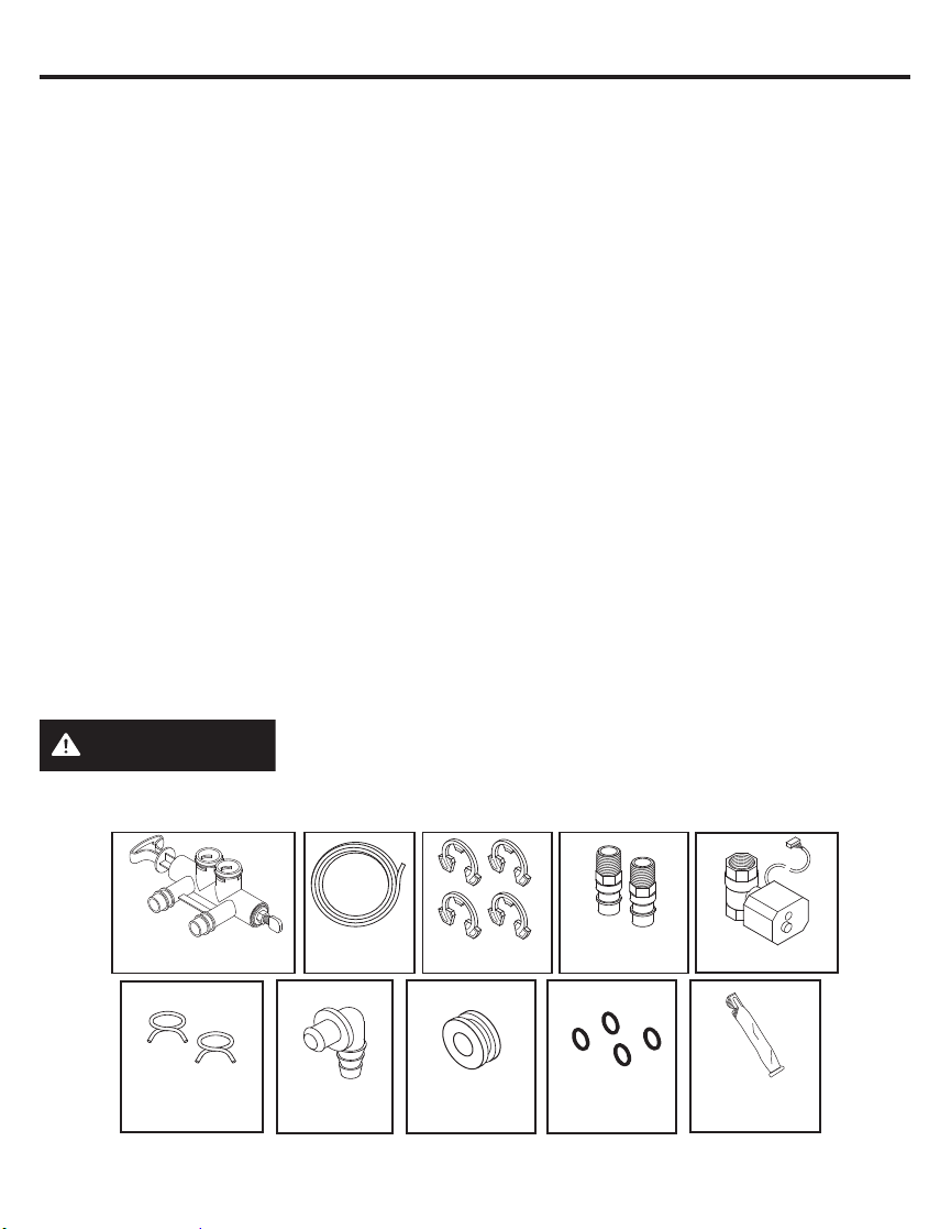
INSPECT SHIPMENT
Make sure all the parts shown below are present. Additional parts must be purchased to complete
the installation. Thoroughly check the water softener for possible shipping damage and parts loss.
Also inspect and note any damage to the shipping carton.
Remove and discard (or recycle) all packing materials. To avoid loss of small parts, we suggest
you keep the small parts in the parts bag until you are ready to use them.
2 fittings to connect household plumbing to
1” NPT threads on softening adaptors.
Additional installation parts may be required:
• UL-approved grounding clamps and
6-gauge copper grounding wire.
WARNING
NOTE: Failure to comply with these installation instructions will void the product warranty,
and the installer will be responsible for any service, repair or damages caused thereby.
Bypass Valve Drain Hose Clips
Hose Clamps
Discard all unused parts and packaging material after installation.
Small parts remaining after the installation could be a choke hazard.
Overflow
Adapter
Installation
Adaptors
Grommet O-rings
7
Shutoff Valve
Silicone
Grease
Page 8
Installation Requirements
LOCATION REQUIREMENTS
Consider all of the following when selecting an
installation location for the water softener.
Do not locate the water softener where freezing
temperatures occur. Do not attempt to treat
water over 120ºF. Freezing temperatures or
hot water damage voids the warranty.
To condition all water in the home, install
the water softener close to the water supply
inlet, and upstream of all other plumbing
connections, except outside water pipes.
Outside faucets should remain on hard water
to avoid wasting conditioned water and salt.
A nearby drain is needed to carry away regeneration
discharge (drain) water. Use a floor drain,laundry
tub, sump, standpipe, or other options(check your
local codes). See “Air Gap Requirements” and
“Valve Drain Requirements”sections.
The water softener uses a direct plug-in external
power supply (included). Be sure to use the included
power supply and plug it into a nominal 120V, 60
cycle household outlet that is in a dry location only,
grounded and properly protected by an over current
device such as a circuit breaker or fuse.
Always install the water softener between
the water inlet and water heater. Any other
installed water conditioning equipment should
be installed between the water inlet and
water softener (See Figure below).
If installing the water softener outdoors, do
not locate where it will be exposed to wet
weather, direct sunlight, extreme hot or cold
temperatures, or other forms of abuse.
PROPER ORDER TO INSTALL WATER TREATMENT EQUIPMENT
Untreated Water to
Cold Water to House
Hot Water to House
Outside Faucets
DO NOT RUN HOT WATER THROUGH THE
SOFTENER. Temperature of water passing
through the softener must be less than 120° F.
Avoid installing in direct sunlight. Excessive
sun heat may cause distortion or other
damage to non-metallic parts.
When installing in an outside location you
must take steps necessary to assure the
softener, installation plumbing and wiring, are
protected from the elements, direct sunlight,
contamination, vandalism, insects, vermin, etc.
Do not install the softener where it would block
access to the water heater or access to the
main water shutoff.
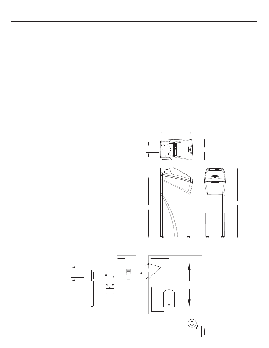
DIMENSIONS
22-7/16"
IN
Optional
Sediment
Filter
3-3/4"
OUT
TOP VIEW
IN - OUT
41-1/2"
City Water Supply
Shut off
valve
Pressure
Tank
14-7/16"
OR
47-5/8"
FRONT VIEW SIDE VIEW
Water
Heater
Water
Softener
Well Water Supply
Well
Pump
8
Page 9
Installation Requirements
PLUMBING CODES
All plumbing must be completed in accordance
with national, state and local plumbing codes.
In the state of Massachusetts: The
Commonwealth of Massachusetts plumbing
code 248-CMR shall be adhered to. A licensed
plumber shall be used for this installation.
AIR GAP REQUIREMENTS
A drain is needed for regeneration water (See
Figure 1). A floor drain, close to the water
softener, is preferred. A laundry tub, standpipe,
etc. are other drain options. Secure valve
drain hose in place. Leave an air gap of 1-1/2”
between the end of the hose and the drain. This
gap is needed to prevent back flow of sewer
water into the water softener. Do not put the
end of the drain hose into the drain.
1-1/2”
air gap
FLOOR
DRAIN
Drain
Hose
1-1/2”
air gap
STANDPIPE LAUNDRY
Drain
Hose
TUB
Drain
Hose
1-1/2”
air gap
Figure 1
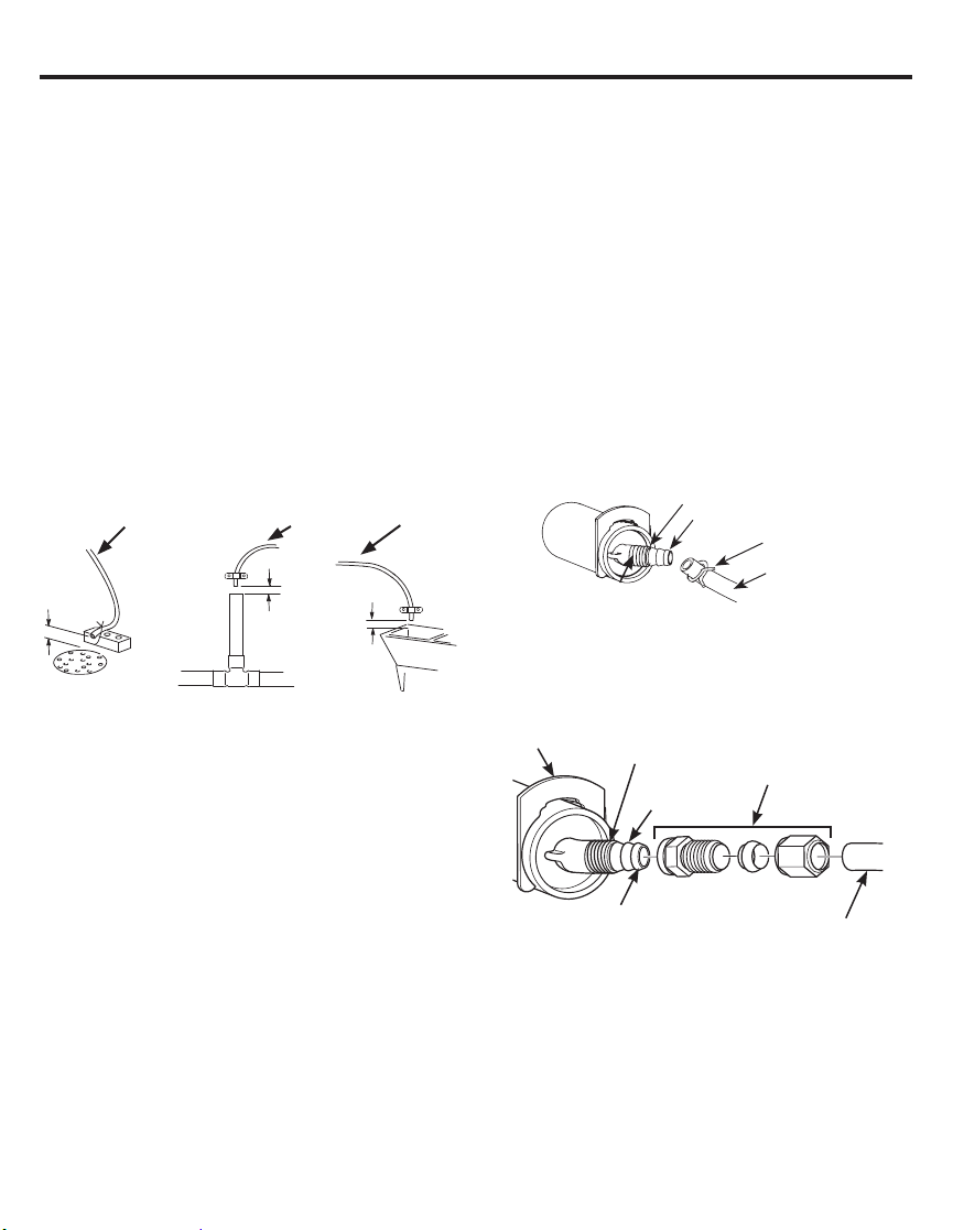
VALVE DRAIN REQUIREMENTS
Using the flexible drain hose (included) (See
Figure 2), measure and cut to the length
needed. Flexible drain hose is not allowed in all
localities (check your plumbing codes). If local
codes do not allow use of a flexible drain hose,
a rigid valve drain run must be used. Purchase
a compression fitting (1/4 NPT x 1/2 in.
minimum tube) and 1/2” tubing from your local
hardware store. Plumb a rigid drain as needed
(See Figure 3).
NOTE: Avoid drain hose runs longer than 30
feet. Avoid elevating the hose more than 8 feet
above the floor. Make the valve drain line as
short and direct as possible.
FLEXIBLE DRAIN LINE
1/4” NPT Thread
Barbs for 3/8Ǝ I.D. tubing
Hose clamp
Drain hose
Drain hose adapter
Figure 2
RIGID DRAIN LINE
Compression fitting
Clip
1/4Ǝ NPT thread
137[Ǝ2'
tube (not provided)
Barbs
Cut barbs from valve drain
elbow (pull clip and remove
drain valve elbow from valve)
9
ƎRXWVLGH
diameter
copper tube
(not provided)
Figure 3
Page 10
Installation Requirements
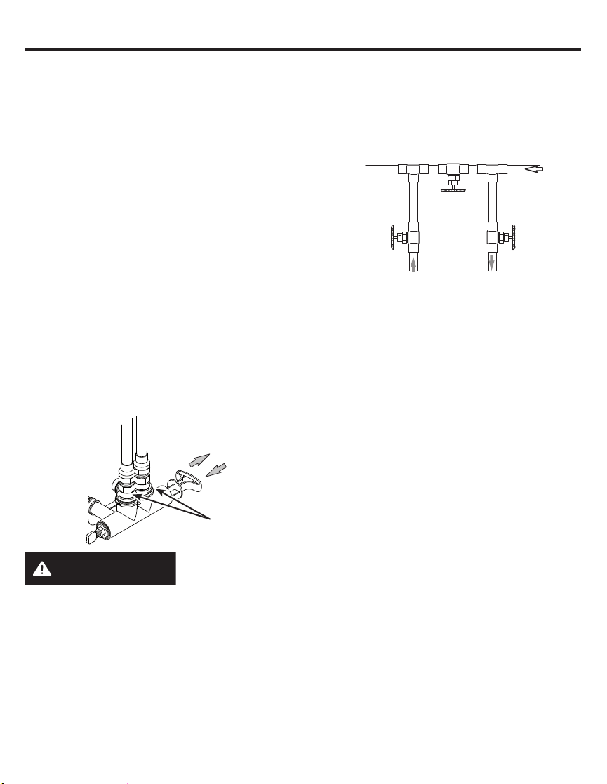
INLET/OUTLET PLUMBING
REQUIREMENTS
Always install either a single bypass valve
(provided),as shown in Figure 4, or, if desired,
parts for a 3 valve bypass system (not
included) can be purchased and assembled, as
shown in Figure 5. Bypass valves allow you to
turn off water to the softener for maintenance if
needed, but still have water in house pipes.
Pipe fittings must be 1/2” minimum.
Use:
Copper pipe
Threaded pipe
PEX (Crosslinked Polyethylene) pipe
CPVC plastic pipe
Other pipe approved for use with potable
water
IMPORTANT: Do not solder with plumbing
attached to installation adaptors and single
bypass valve. Soldering heat will damage the
adaptors and valve.
SINGLE BYPASS VALVE
Pull out for “Service”
(Soft water)
Push in for
“Bypass”
3-VALVE BYPASS SYSTEM
For soft water service: Open the inlet and
outlet valves and close the bypass valve.
For bypass hard water: Close the inlet and
outlet valves and open the bypass valve.
3 VALVE BYPASS
Bypass
Valve
Outlet
Valve
From Water
Softener
To Water
Softener
Inlet
Valve
Figure 5
Installation
adaptors
Figure 4
WARNING
A copper or
galvanized cold water pipe may be used to
ground electrical outlets in the home. Failure to
maintain this ground path may result in an
electric shock hazard. If the cold water pipe is
used to ground electric outlets, please refer to
Installing the Ground Wire section before
cutting the pipe.
10
Page 11
Installation Instructions
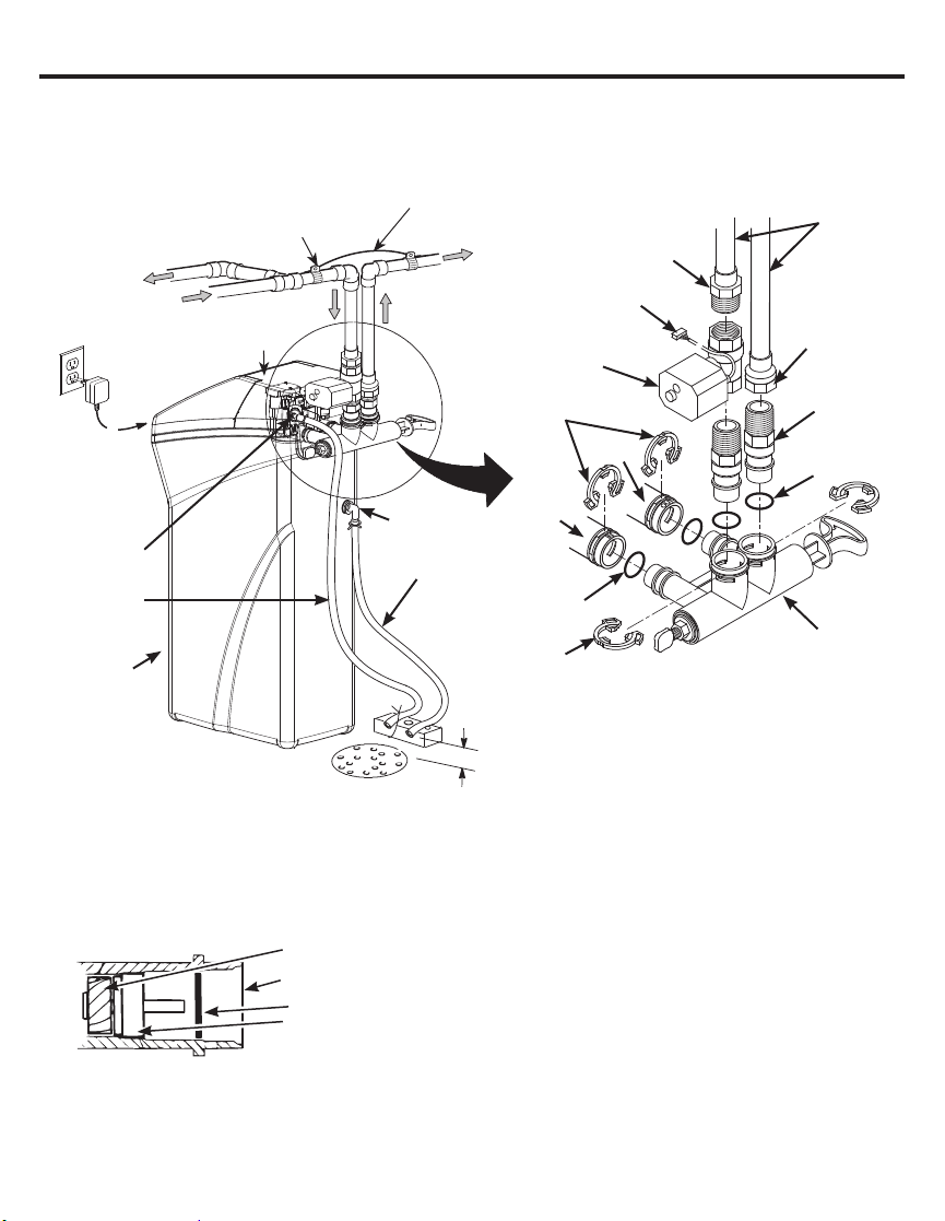
TYPICAL INSTALLATION
Hard Water
to Outside
Faucets
Incoming
Hard Water
Plug-in
Transformer
To
Controller
Drain Hose
Adapter
Valve Drain
Hose*
Brine Tank
(Salt Storage)
*Do not connect the water
softener valve drain hose to
the brine tank overflow
Clamp
(not included)
Top
Cover
Figure 6
Overflow
Adapter
Floor Drain
Ground Wire
(not included)
Conditioned
Water
Main Water Pipe
Motorized Water
Shutoff valve
Inlet
Brine Tank
Overflow Hose*
Lubricated
O-ring
Clips
Secure Valve Drain
Hose in place over Floor
Drain
1-1/2”
air gap
1” NPTM
Threaded
Adaptor (not
included)
Plug into
controller
Clips
Outlet
Pipe
1” NPTF
Sweat
Adaptor
(not
included)
1” NPTM
Threaded
Adaptor
O-ring
Single Bypass
Valve
Figure 7
NOTE: See “Air Gap Requirements” section.
• Remove plastic shipping plug and wire from valve outlet.
Turbine
Valve outlet
Plastic shipping plug
Turbine shaft and support
Figure 8
NOTE: Be sure the turbine and support are firmly in place
in the valve outlet. Blow into the valve port and observe the
turbine for free rotation.
11
Page 12
Installation Instructions
TURN OFF WATER SUPPLY
1. Close the main water supply valve, located
near the well pump or water meter.
2. Open all faucets to drain all water from
house pipes.
NOTE: Be sure not to drain water from the
water heater, as damage to the water heater
elements could result.
INSTALL BRINE TANK OVERFLOW ADAPTER
Install the brine tank overflow grommet and
adapter in the 13/16” diameter hole in the back
of the salt storage tank sidewall, (see Figure 9).
NOTE: The brine tank overflow adapter accepts
either 1/2” or 3/8” I.D. hose.
INSTALL THE BYPASS VALVE
NOTE: For easier installation, remove the top
cover. Release 2 clips at rear of cover. Rotate
cover forward and lift up.
1. Remove two clips from the water softener
valve inlet and outlet ports and visually check
and remove any debris, (see Figure 7).
2. Make sure the turbine assembly spins freely
in the”out” port of the valve, (see Figure 8).
3. If not already done, put a light coating of
silicone grease (provided) on the single
bypass valve o-rings, (see Figure 7).
4. Push the single bypass valve into the
softener valve as far as it will go. Snap the
two large holding clips into place, from the
top down, (see Figure 7 and 10).
IMPORTANT: Be sure the clips snap firmly into
place so the single bypass valve will not pull out.
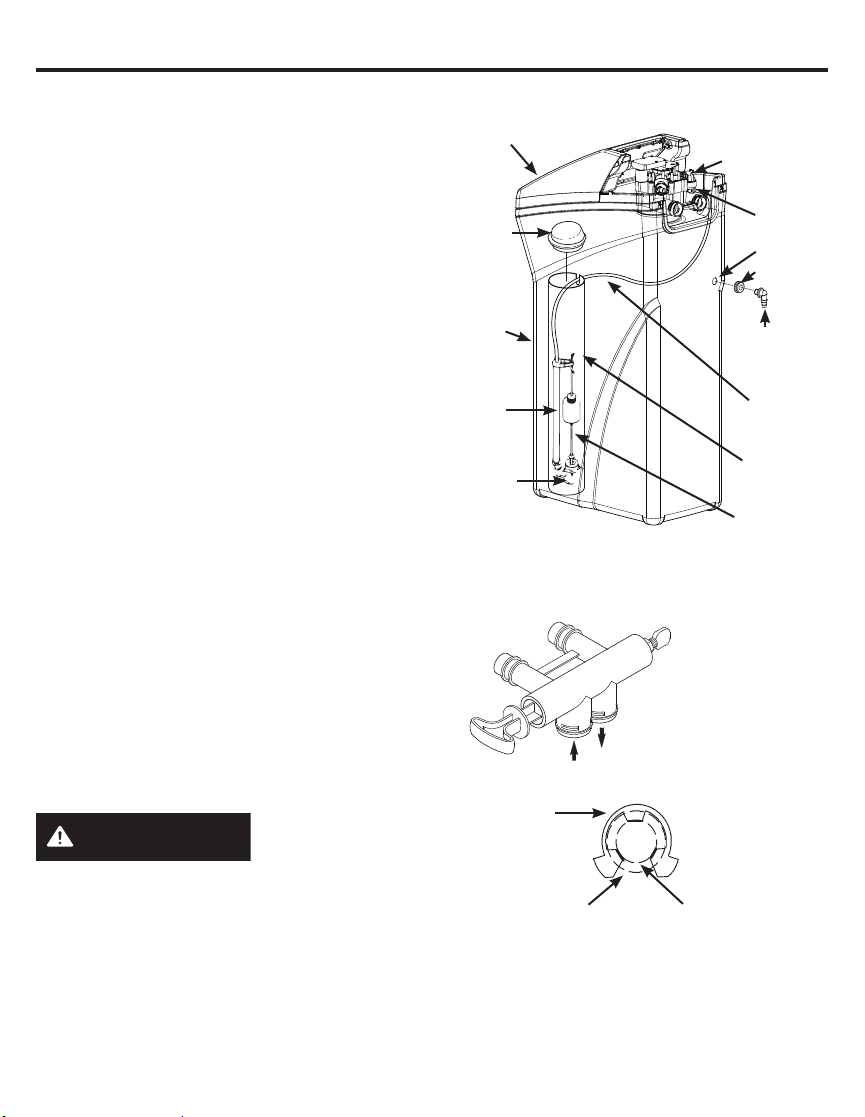
MOVE WATER SOFTENER INTO PLACE
WARNING
Use two or more people to move and install
water Softener Failure to do so can result in
back or other injury.
1. Move the water softener into the desired
location. Set it on a solid, level surface.
IMPORTANT: Do not place shims directly
under the salt storage tank to level the softener.
The weight of the tank, when full of water and
salt, may cause the tank to fracture at the shim.
Excessive Weight
Hazard
Salt
Cover
Brinewell
Cover
Brine
Tank
Stand
Tube
Brine
Valve
Assembly
Nozzle Venturi
Assembly
Nut - Ferrule
Hole
Grommet
Brine Tank
Overflow
Adapter
Brine
Tubing
Brinewell
Float Stem
Figure 9
NOTE: Unit is shown with top cover removed.
SINGLE BYPASS VALVE
If connecting to floor
level plumbing, install
the bypass valve turned
downward, as shown.
CORRECT ASSEMBLY
Clip
Outside diameter of
water softener valve
inlet & outlet
Outside diameter
of clip channel on
single bypass valve
Figure 10
NOTE: Be sure all 3 tabs of the clip go through
the matching holes on the water softener valve
inlet or outlet, and fully into the channel on the
single bypass valve. Make sure that the tabs
are fully seated.
12
Page 13
Installation Instructions
GETTING ACCESS TO MAIN CONTROL BOARD
(TO PLUG IN WATER SHUTOFF VALVE)
INSTALL MOTORIZED WATER
SHUTOFF VALVE
Install the included water shutoff valve on the
threaded installation adapter leading to the
water softener’s INLET. Optionally, it may be
installed elsewhere in the plumbing upstream of
the water softener inlet, making sure that the 10
foot long cable will reach the water softener’s
main control board (see illustration). The shutoff
valve’s inlet and outlet are female 1” NPT.
Support the weight of the shutoff valve.
After completing plumbing, make sure that
the water softener is not powered up, and
plug the cable from the shutoff valve into the
corresponding connector on the main control
board (see illustration at right).
NOTE: The shutoff valve may be operated
manually by pulling out and turning the knob
on the shutoff valve body, although there is no
need to do this when installing.
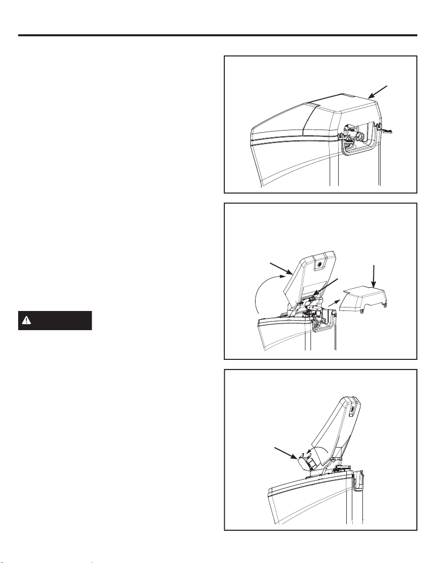
CAUTION
when it is plugged into the electronic controller.
Do not place fingers into
the motorized shutoff valve
1. Pull out both tabs on back of the top cover
to unlock cover.
2. Tilt top cover upward and lift off.
3. Open salt lid and tilt back until is rests.
4. Pull both tabs toward center to unlock
faceplate.
Salt Lid
Top Cover
Top Cover
Faceplate
5. Tilt faceplate forward to expose back of
the control board.
Faceplate
13
Page 14
Installation Instructions
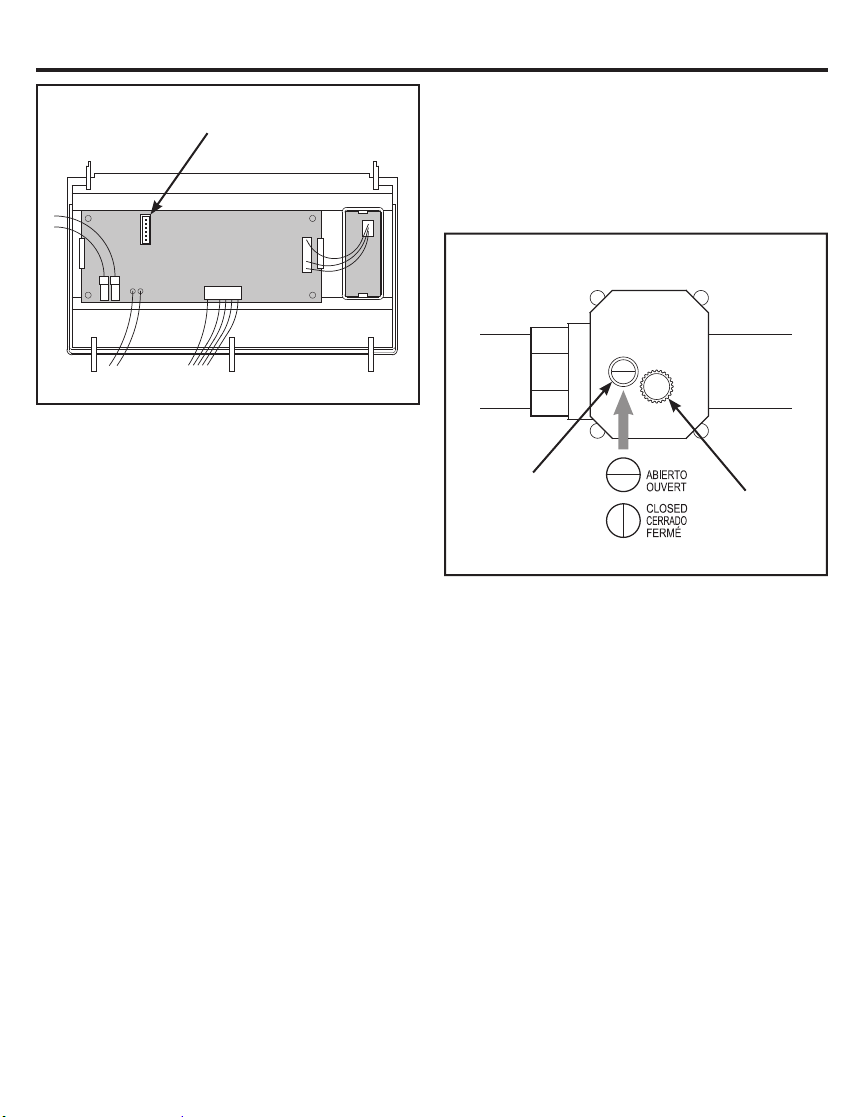
6. With power off, plug the shutoff valve’s
cable into this connector.
Main
Control Board
Back of Faceplate Assembly
MOTORIZED WATER SHUTOFF VALVE
To manually operate the motorized water
shutoff valve, pull out the round knob on the
valve and turn it until the red line in the sight
glass matches the desired (open or closed)
position. See illustration below.
Motorized Water Shutoff Valve
OPEN
Sight glass
Knob – Pull
out to turn
14
Page 15
Installation Instructions
COMPLETE INLET AND OUTLET
PLUMBING
WARNING
galvanized cold water pipe may be used to
ground electrical outlets in the home. Failure to
maintain this ground path may result in an
electric shock hazard. If the cold water pipe is
used to ground electric outlets, please refer to
Installing the Ground Wire section before
cutting the pipe.
IMPORTANT: This water softener has a nonmetallic valve system. Installing it on metal
plumbing will break electrical continuity, which
may interrupt grounding for the home. You
must restore electrical continuity in your metal
plumbing system.
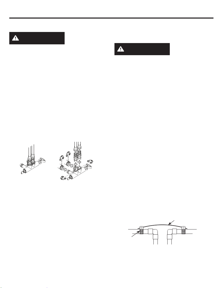
If you install a 3-valve bypass system (Figure
5), electrical continuity will be maintained. If you
install the non-metallic bypass valve (Figure
11), please refer to the Installing the Ground
Wire section before cutting the pipe.
Figure 11
Measure, cut, and loosely assemble pipe and
fittings from the main water pipe to the inlet
and outlet ports of the water softener valve. Be
sure to keep fittings fully together, and pipes
squared and straight.
BE SURE INCOMING HARD WATER SUPPLY
IS DIRECTED TO THE SOFTENER VALVE
INLET PORT.
NOTE: Inlet and outlet are marked on the water
softener valve. Trace the water flow direction to
be sure hard water is to inlet.
IMPORTANT: Be sure to fit, align and support
all plumbing to prevent putting stress on the
water softener valve inlet and outlet. Stress
from misaligned or unsupported plumbing may
cause damage to the valve.
A copper or
• If making a soldered copper installation, do all
sweat soldering before connecting pipes to
the NPT adapters and bypass valve. Torch
heat will damage plastic parts.
WARNING
make pipe connection use only lead free
solder and flux to prevent lead poisoning.
• When turning threaded pipe fittings onto
plastic fittings, use care not to cross-thread.
• Use Teflon Tape on all external pipe threads.
Complete the inlet and outlet plumbing for the
type of pipe you will be using. Secure ground
clamp to metal pipes.
INSTALLING THE GROUND WIRE
NOTE: If your house plumbing is plastic, it
would not be used as a grounding path, and
this step should be skipped.
IMPORTANT: A copper or galvanized cold
water pipe is often used to ground electrical
outlets in the home. Grounding protects you
from electrical shock. The water softener
may have broken this ground path. To restore
connection, install a 12”-long, 6-gauge
copper wire across and tightly clamp using
UL-approved 1/2”–1” bronze grounding clamps
at both ends as shown (Figure 12). Zinc clamps
should not be used on copper plumbing. Wire
and clamps may be purchased separately from
your local hardware store.
1.
Clean copper pipe and ends of wire with emery
paper. Bare wire is recommended. If insulated
wire is used, is should be stripped 3/4” at each
end before cleaning with emery paper.
2. Attach bronze clamps to pipe. Tighten screws.
3. Attach to clamps as shown. Tighten screws.
Clamp (2)
NOTE: If you are installing a sediment filter or
other item(s) into the plumbing system, along
with the water softener, be sure to restore
electrical continuity across all removed metal
pipe sections.
15
If solder is used to
Ground Wire
Figure 12
Page 16
Installation Instructions
INSTALL VALVE DRAIN HOSE
1. Measure and connect the 3/8”drain line
(provided) to the water softener valve drain
fitting. Use a hose clamp to hold the hose in
place.
NOTE: Avoid drain hose runs longer than 30
feet. Avoid elevating the hose more than 8 feet
above the floor. Make the valve drain line as
short and direct as possible.
IMPORTANT: If codes require a rigid drain line
see “Valve Drain requirements” section.
2. Route the drain hose or copper tubing
to the floor drain or other suitable drain
point. Secure drain hose. This will prevent
“whipping’’ during regenerations. See “Air
Gap Requirements” section (Figure 1).
3. Cut and secure the hose.
NOTE: The softener will not work if the water
cannot exit the drain hose during recharge.
INSTALL BRINE TANK (SALT
STORAGE) OVERFlOW HOSE
1. Measure, cut to needed length and connect
the 3/8”drain line (provided) to the salt
storage tank overflow elbow and secure in
place with a hose clamp.
2. Route the hose to the floor drain, or other
suitable drain point no higher than the drain
fitting on the salt storage tank (This is a
gravity drain). If the tank overfills with water,
the excess water flows to the drain point. Cut
the drain line to the desired length and route
it neatly out of the way.
IMPORTANT: For proper operation of the water
softener, do not connect the water softener
valve drain tubing to the salt storage tank
overflow hose.
RINSE OUT CARBON FINES
Small particles of carbon filtration material are
generated during manufacturing and shipping.
These particles will exit the media tank with
the first water that flows through the softener.
These carbon “fines” are not harmful, but give
the water a gray color and should be rinsed
down the drain before any water from the
softener is directed to the home’s faucets or
water heater.
TEST FOR LEAKS
To prevent air pressure in the water softener
and plumbing system, complete the following
steps in order:
1. Fully open two or more softened cold water
faucets close to the water softener, located
down stream from the water softener.
Place the bypass valve (single or 3 valve)
2.
into the”bypass” position (see Figures 4 or 5).
3. Slowly open the main water supply valve.
Run water until there is a steady flow from
the opened faucets, with no air bubbles.
4. Place bypass valve(s) in “service” or soft
water position as follows:
• Single bypass valve (Figure 4): Slowly
move the valve stem toward “service,”
pausing several times to allow the water
softener to fill with water.
•
3 valve bypass (Figure 5): Fully close the
bypass valve and open the outlet valve. Slowly
open the inlet valve, pausing several times to
allow the water softener to fill with water.
5. After about three minutes, open a hot water
faucet until there is a steady flow and there
are no air bubbles, then close this faucet.
6.
Close all cold water faucets and check for leaks
at the plumbing connections that you made.
7. Check for leaks around clips at softener’s
inlet and outlet. If a leak occurs at a clip,
depressurize the plumbing (turn off the water
supply and open faucets) before removing
clip. When removing clips at the softener’s
inlet or outlet, push the single bypass valve
body toward the softener (See Figure 14).
Improper removal may damage clips. Do not
reinstall damaged clips.
If removing
clips.....
....depressurize the
plumbing, then push
Bypass Valve body
Figure 14
16
toward softener
Page 17

Installation Instructions
ADD WATER AND SALT TO THE SALT
STORAGE TANK
WARNING
EXCESSIVE WEIGHT HAZARD:
Use two or more people to move and lift salt
bags. Failure to do so can result in back or
other injuries.
1. Using a container, add about three gallons of
clean water into the salt storage tank.
2. Add salt to the storage tank. Use nugget,
pellet or coarse solar salts with less than 1%
impurities.
PLUG IN THE WATER SOFTENER
1. Plug the water softener into an electrical
outlet that is not controlled by a switch.
2. Replace the top cover.
3. Replace the salt hole cover.
NOTE: The water heater is filled with hard
water and,as hot water is used, it will refill
with conditioned water. In a few days, the hot
water will be fully conditioned. To have fully
conditioned hot water immediately, wait until
the initial recharge is over. Then, drain the
water heater(following instructions for water
heater) until water runs cold.
SANITIZE THE WATER SOFTENER /
SANITIZE AFTER SERVICE
1. Open salt hole cover, remove the brinewell
cover and pour about 3 oz. (6 tablespoons)
of household bleach into the softener
brinewell. Replace the brinewell cover.
2. Make sure the bypass valve(s) is in the
“service”(open) position.
3. Start a recharge (regeneration). See “Start a
Recharge”on Page 17.
4. After the recharge has completed, fully open
a cold water faucet, downstream from the
softener, and allow 50 gallons of water to
pass through the system. This should take at
least 20 minutes. Close the faucet.
WARNING
Discard all unused
parts and packaging material after
installation. Small parts remaining after the
installation could be a choke hazard.
17
Page 18
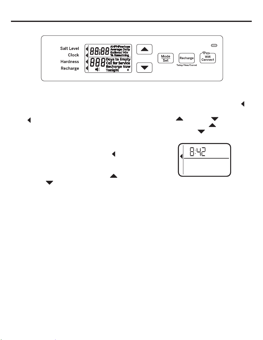
Programming the Water Softener
When the transformer is plugged into the
electrical outlet, a model code and test number
(example: y4.1 & H40) are shown in the
display. Then, “12:00 PM” begins to flash. An
arrow
face plate decal.
CONTROL OPERATION:
• CONTROL SETTINGS REQUIRED upon
• Use the MODE/SET button to scroll arrow to
• After the mode is selected use the UP
• Press the MODE/SET button to accept
• A “beep” sounds while pressing buttons for
is displayed next to CLOCK on the
initial installation and after an extended power
outage.
desired control function set.
and DOWN
settings of the control.
changes.
control programming. One beep signals a
change in the control display. Repeated
beeps mean the control will not accept a
change from the button you have pressed,
and you should select another button.
buttons to change the
SET TIME OF DAY
1. Press MODE/SET button until the arrow
points to CLOCK.
2. Press the UP
to set the present time. UP
display ahead; DOWN
back. Be sure AM and PM is correct.
Salt Level
Clock
Hardness
Recharge
NOTE: Press buttons and quickly release
to slowly advance the display one number
at a time. Hold the buttons down for fast
advance.
3. When the correct time is shown in the
display, press MODE/SET to accept.
or DOWN buttons
moves the
sets the time
PM
18
Page 19
Programming the Water Softener
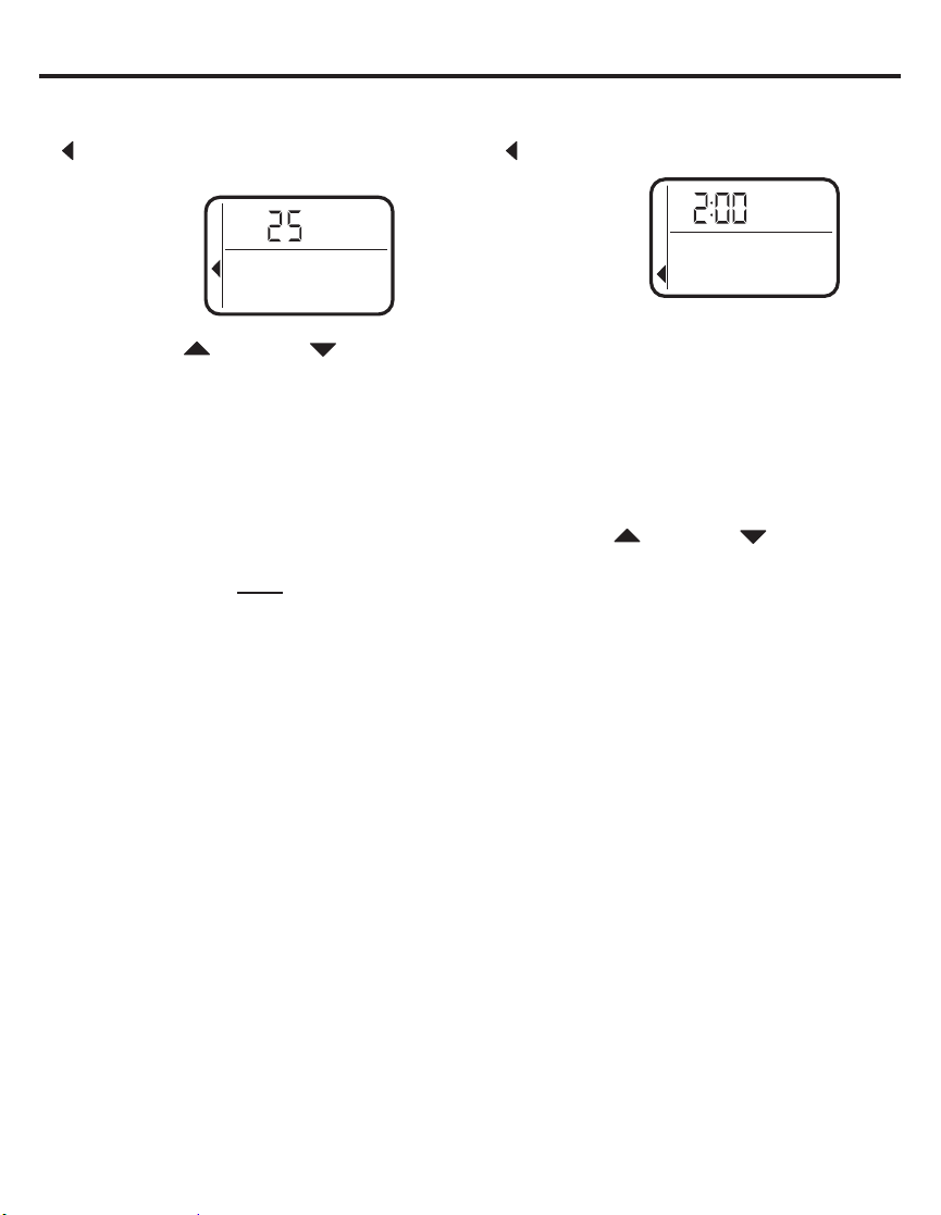
SET WATER HARDNESS NUMBER
1. Press the MODE/SET button until the arrow
points to HARDNESS. A flashing 25 will
appear in the display.
Salt Level
Clock
Hardness
Recharge
2. Press the UP
set your water hardness number.
NOTE: If your water supply contains iron,
compensate for it by adding to the water
hardness number. For example, assume
your water is 20 gpg hard and contains 2
ppm iron. Add 5 to the hardness number
for each 1 ppm or iron. In this example, you
would use 30 for your hardness number.
20 gpg hardness
2 ppm iron x 5 = 10 +10
(times) 30 HARDNESS NUMBER
3.
When the display shows your water
hardness (in grains per gallon), press
MODE/SET to accept.
You can get the grains per gallon (gpg)
hardness of your water supply from a
water analysis laboratory. If you are on
a municipal supply, call your local water
department. Or call Legend Technical
Services, an independent laboratory,
to request a water hardness test kit at
1.800.949.8220, Option 4. If your report
shows hardness in parts per million (ppm)
or milligrams per liter (mg/l), simply divide
by 17.1 to get the equivalent number of
grains per gallon.
or DOWN buttons to
SET RECHARGE (STARTING) TIME
1. Press the MODE/SET button until the arrow
points to RECHARGE.
Salt Level
Clock
Hardness
Recharge
NOTE: A flashing 2:00 AM (factory default)
should show in the display. This is a good
time for recharge to start (takes about 2
hours) in most households because water
is not in use. HARD WATER is bypassed to
house faucets during recharge.
If no change is needed, go to step 3. To
Change the recharge starting time, follow
step 2.
2.
Press UP
or DOWN
the desired recharge start time. Be sure
to observe the AM or PM as you did when
setting the time of day.
3.
Press the MODE/SET button to accept.
AM
button to set
19
Page 20
Programming the Water Softener
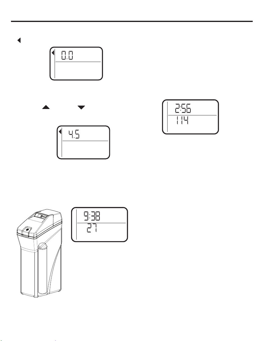
SET SALT LEVEL
1. Press the MODE/SET button until the arrow
points to SALT LEVEL.
Salt Level
Clock
Hardness
Recharge
2. Determine level of salt in brine tank using the
numbered scale on side of brine well, inside
brine tank (see Figure 15).
Press UP
3.
or DOWN
the SALT LEVEL to correspond to level on
button to set
the numbered scale in brine tank.
Salt Level
Clock
Hardness
Recharge
NOTE: Each press of a button changes the
level by increments of 0.5 up to 8.0.
Lowering the salt level below zero turns the
SALT LEVEL indicator OFF.
Press the MODE/SET button to accept. The
4.
display shows the present time of day and
DAYS TO EMPTY.
PM
Days to Empty
8
7
6
5
4
3
2
1
Figure 15
DAYS TO EMPTY
The words DAYS TO EMPTY and a number
are shown in the lower half of the display. This
information is shown in the normal run display.
This is to inform the user of the number of
days before the salt level in the brine tank
reaches Level 0. There will be salt left in the
salt tank, but it may not be sufficient to fully
recharge the system. Salt should be added
at this time to avoid hard water. The value is
updated daily and whenever the SALT LEVEL
value is changed.
AM
Days to Empty
NOTE: For the first several weeks of operation,
the DAYS TO EMPTY may provide erratic
operation. For example, the blue indicator light
may flash, showing that more salt is required
when the actual salt level in the tank is well
above the Level 0. In some cases, the DAYS
TO EMPTY may even increase over a several
week period.
It takes a couple of months for the water
softener to learn your water usage pattern.
Once it does this, it will accurately determine
actual salt usage pattern. During this first
period, check salt level when blue indicator
light flashes. If the salt level in the tank is at
Level 1 or above, allow system to run. Be sure
to reset your salt level indicator each time you
add salt to the system.
START A RECHARGE
Press the RECHARGE button and hold for
three seconds, until “RECHARGE NOW”
begins to flash in the display, starting a
recharge. This recharge draws the sanitizing
bleach or brine into and through the water
softener. Any air remaining in the water
softener is purged to the drain. During this time
periodically check for leaks.
NOTE: As with all other water system
applications, leaks may occur. Leaks may not
be immediately apparent. Recheck 24 hours
after first recharge cycle is complete.
20
Page 21
Appliance Communication: WiFi Connect
(For customers in the United States, its Territories, and Canada)
• WiFi communication requires WiFi
connectivity and electrical power at the
location of the softener. App connectivity will
not function should either fail. (Check for
both before the system is fully installed.)
• App requires smart phone with service to
receive notifications.
• App provides alert, but requires user to
respond to turn off water.
• The system is not able to detect all small
leaks, and cannot shut off leaks between the
system and shut off valve.
This device complies with Part 15 of the FCC Rules.
Operation is subject to the following two conditions:
1. This device may not cause harmful interference, and
2. This device must accept any interference received, including interference that may cause
undesired operation. This equipment has been tested and found to comply with the limits for
a Class B digital device, pursuant to Part 15 of the FCC Rules. These limits are designed to
provide reasonable protection against harmful interference in a residential installation. This
equipment generates uses and can radiate radio frequency energy and, if not installed and used
in accordance with the instructions, may cause harmful interference to radio communications.
However, there is no guarantee that interference will not occur in a particular installation. If
this equipment does cause harmful interference to radio or television reception, which can be
determined by turning the equipment off and on, the user is encouraged to try to correct the
interference by one or more of the following measures:
• Reorient or relocate the receiving antenna.
• Increase the separation between the equipment and receiver
• Connect the equipment into an outlet on a circuit different from that to which the receiver is
connected.
• Consult the dealer or an experienced radio/television technician for help.
Labelling: Changes or modifications to this unit not expressly approved by the manufacturer could
void the user’s authority to operate the equipment.
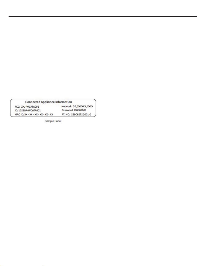
If your Water Softener is GE Appliances WiFi
Connect capable, a WiFi communication
card is built into the product allowing it to
communicate with your smartphone for remote
monitoring, control, and notifications.
To connect with your softener, please
visit
GEAppliances.com/connect to
learn how to connect your appliance to your
smartphone using the label located inside your
softener and learn about the features of your
app such as 1) Water usage monitoring 2) Low
Salt Alert 3) Continuous water flow alerts 4)
Remote water shutoff valve.
WiFi Connectivity: For assistance with your
appliance network connectivity, please call
GE Appliances at 1-800 220-6899.
21
Page 22
Programming the Water Softener
OPTIONAL CONTROL SETTINGS
The controller display has several options and
features.
LOW SALT ALARM
The LOW SALT ALARM,
when enabled, will sound
the beeper when the DAYS
TO EMPTY value is 15
days or less. To change this
setting, press and hold the MODE/SET button
for 3 seconds or hear a beep. ON (factory
default) or OFF will flash in the display. Press
the UP
this feature ON or OFF. Press the MODE/SET
or DOWN
buttons to toggle
button to accept, and the display will move to
the SALT EFFICIENCY screen.
SALT EFFICIENCY
When the SALT EFFICIENCY feature is
ON, the unit will operate
at a salt efficiency of
4000 grains of hardness
removed per pound of salt.
This mode of operation
is the most efficient setting for salt usage,
because the system will tend to recharge more
often with less salt usage. Turning the feature
OFF will tend to lengthen the time between
recharge cycles, which will provide the most
efficient usage of water, but may use more salt.
The degree of difference between these two
cycles is highly dependent on the water usage
and hardness at particular installation.
NOTE: California Regulations require this
feature to be ON for installations in California.
To change the setting, press the UP
DOWN
OFF. Press the MODE/SET button to accept,
buttons to toggle this feature ON or
or
and the display will move to the PRERINSE
ON/OFF screen.
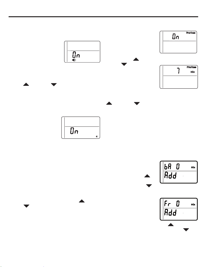
PRERINSE
If your water contains
sediment, the prerinse
feature will remove
sediment from the resin
bed prior to regeneration.
Press the UP
DOWN
prerinse ON or OFF.
Press the MODE/SET
button to accept, and the
display will move to SET
PRERINSE TIME screen.
In this screen, you can adjust the duration of
the prerinse, in minutes, by pressing the UP
or DOWN
SET button to accept, and the display will
move to the ADD BACKWASH TIME screen.
BACKWASH AND FAST RINSE
If you experience salty tasting water after
regeneration, you may need to increase the
backwash and fast rinse times. The cycle times
during regenerations are determined by the
softener’s electronic controller. However, you
may Increase the backwash and fast rinse
times. You may add up to 10 minutes.
For Backwash, you can
add up to 10 minutes
in 1 minute increments,
by pressing the UP
button, or subtract time by
pressing the DOWN
button.
For Fast Rinse, press
MODE/SET and the
display moves to the
ADD FAST RINSE TIME
screen. You can add up
to 10 minutes in 1 minute
increments, by pressing the UP
or subtract time by pressing the DOWN
button. Press the MODE/SET button to accept,
and the display will move to the Run Display
screen.
or
buttons to turn
buttons. Press the MODE/
button,
22
Page 23
Programming the Water Softener
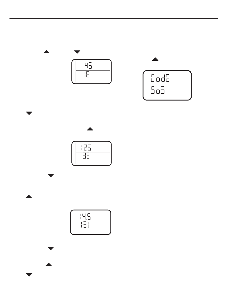
FEATURE: OTHER DATA DISPLAY
These models have an option to have the
run display indicate different information. The
information displayed on the top half of the
display can be changed to one of the following
by pressing UP
• CAPACITY REMAINING
– This is the percentage
of water softening capacity
remaining. Immediately
after a regeneration, 100%
shows. As water is used,
the percentage will decrease until the next
regeneration. During regenerations, the
percentage increments upward.
When present time is displayed, press the
DOWN
button; % Remaining will appear in
the display. The value shown is between 0 and
100 percent. This value is based on current
operating capacity. Pressing the UP
will return the screen to the previous display.
• AVERAGE DAILY
GALLONS – The figure
displayed is the average
gallons of water used by the
household each day over
the past seven-day period.
Press the DOWN
the Average Daily Gallons. Average Daily
Gallons will appear in the display. This value
is updated every night at midnight. Pressing
the UP
button will return the screen to the
previous display.
• FLOW RATE, GPM
– When using soft water,
this display shows the flow
rate passing through the
softener (in gallons per
minute). Zero shows if water
is not passing through the softener.
Press the DOWN
the flow rate. Gallons/Min will appear in the
display. This value is updated every
Pressing the UP
screen to the previous display. Pressing the
DOWN
button will return the screen to the
present time display.
or DOWN
buttons
Days to Empty
Recharge
Tonight
Days to Empty
Recharge
Tonight
% Remaining
Average Daily
Gallons
button again to display
Gallons/Min
Days to Empty
button again to display
1
»2 second.
button will return the
:
button
RESETTING TO FACTORY DEFAULT
To reset the electronic controller to its factory
default for all settings (time, hardness, etc.):
1. Press the MODE/SET button and hold
until the display changes twice to show the
flashing mode code.
2. Press the UP
“SoS”.
3. Press the MODE/SET button and the
electronic controller will restart.
4. Set the present time, hardness, etc, as
described in the Programming the Water
Softener section
23
button to display a flashing
Page 24

Programming the Water Softener
POWER OUTAGE MEMORY
If electrical power to the water softener is
lost, “memory’’ built into the timer circuitry will
keep all settings for up to 6 hours. While the
power is out, the display is blank and the water
softener will not regenerate. When electrical
power is restored, the following will occur:
Reset the present time only if the display is
flashing. The HARDNESS and RECHARGE
TIME never require resetting unless a change
is desired. Even if the clock is incorrect after
a long power outage, the softener operates
as it should to keep your water soft. However,
regenerations may occur at the wrong time of
day until you reset the clock to the correct time
of day.
NOTE: If the water softener was regenerating
when power was lost, it will now finish the
cycle.
BLUE INDICATOR LIGHT
Steady blue light indicates that the unit is
working correctly. The light flashes when the
unit needs attention from the user.
• Light will also flash when power to the unit
has been interrupted. Check the PRESENT
TIME setting.
• Light flashes and DAYS TO EMPTY flashes -
check salt level and add salt as required.
• Light flashes and Err is in the display -
electrical problem with system.
LOW SALT SIGNAL
When the DAYS TO EMPTY drops to 15, the
blue indicator light and DAYS TO EMPTY in
the display will flash every second and the
alarm will beep every 30 seconds (from 8:00
AM to 8:00 PM), to notify the user that the unit
is running low on salt. As soon as any button
is pressed, the alarm will stop beeping. The
blue indicator light and DAYS TO EMPTY will
continue to flash. Once salt is added to the
brine tank and the SALT LEVEL is reset, the
DAYS TO EMPTY will be reset.
ERROR SIGNALS
If there is an error code
detected, the blue
indicator light will flash
4 times every second,
the display will flash Err
and the alarm will beep
every 30 seconds (from 8:00 AM to 8:00 PM)
to signal that the softener requires service.
The alarm can be turned off by pressing any
button, but the blue indicator light and display
will continue to flash.
Disconnect the transformer from the wall
outlet momentarily, and plug it back in. The
normal display will appear. The motor may run
for several minutes, as the unit resets. If the
problem is not corrected, the error code will
reappear in 8 minutes. If Err 6, 7, or 8 appears,
it can be cleared by pressing recharge for 5
seconds.
See the Before you Call for Service
section to assist in troubleshooting the
water softener.
Call for Service
24
Page 25
Care and cleaning
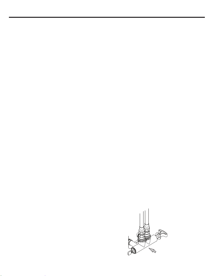
ADJUSTING YOUR WATER HARDNESS
The blend adjusting knob (Figure 16) gives the
ability to finely adjust hardness of the treated
water leaving the water softener. If slightly harder
water is desired than is normally delivered by the
water softener, the blend adjusting knob can divert
a small stream of hard water and blend it with
the soft water entering the home. The amount
of water diverted is controlled by turning a blend
adjusting knob on the end cap of the valve stem.
NOTE: To get full performance from your water
softener leave blending valve in the factory
closed position.
To make adjustments to water hardness:
1. Hold bypass handle to keep the valve stem
from rotating (see Figure 16). Loosen hex
nut on blend adjustment knob by turning the
hex nut counterclockwise (see Figure 17).
2. TO INCREASE HARDNESS:
in the service position (see Figure 16) hold the
handle to keep the valve stem from rotating and
turn the blend adjusting knob counterclockwise
up to 2 turns from the closed position. It is
recommended that adjustments be made in
quarter turn increments over several weeks until
the desired hardness is achieved. NOTE: Once
an adjustment is made to the blend valve knob
the change in water hardness at the homes
faucets or shower heads may take several days
to be noticed. This delay is due to the large
amounts of already conditioned water in the
pipes and water heater that must be exchanged
before a change in hardness can be noticed.
Have the water tested to determine the actual
water hardness.
3. TO DECREASE HARDNESS: With the
bypass in the service position (see Figure
16) hold the handle to keep the valve stem
from rotating and turn the blend adjusting
knob clockwise. When the knob will not turn
anymore, hard water is no longer being
blended into the soft water.
4. Once the desired hardness is achieved
tighten the hex nut (see Figure 17) clockwise
until it comes in contact with the bypass stem.
With the bypass
NOTE: To meet the water softener performance
specifications and reduction of barium and
radium claims the adjustable hardness must be
kept in the “OFF” position. The off position is
achieved when the blend adjusting knob is fully
rotated clockwise until it stops.
SERVICE POSITION
(Normal Softener Operation)
Pull
Handle
Stem
Softener
Valve Outlet
Diverted Hard
Water (Controlled
by blend adjusting
knob)
Soft Water Out
Valve Inlet
Figure 16
Softener
Hard Water In
Blend Adjusting
Knob
Turn counterclockwise
to increase hardness
of treated water
(clockwise to decrease
hardness)
BYPASS POSITION
Hard Water Out
Push
Handle
Figure 17
Hard Water In
Blend Adjusting Knob
If servicing water softener,
turn clockwise as far as it
will go.
Hex Nut
Turn clockwise to lock
blend adjusting knob
(counterclockwise to
unlock).
CAUTION
softener is to be serviced or disconnected from
the bypass valve, the blend adjusting knob must
be turned all the way clockwise to close the
diversion path and prevent water leaking from
the softener valve inlet of the bypass.
25
If the water
Page 26

Care and Cleaning
CHECKING THE SALT STORAGE
LEVEL and REFILL
Brine (salt dissolved in water) is needed for
each and every recharge. The water for making
brine is metered into the salt storage area by
the water softening system valve and control.
However, you must keep the tank supplied
with salt.
ADDING SALT
Lift the salt hole cover and check the salt
storage level frequently. If the water softener
uses all the salt before you refill it, you
will experience hard water. Until you have
established a refilling routine, check the salt
every two or three weeks. Always add if less
than 1/4 full. Be sure the brinewell cover is on.
NOTE: if using potassium chloride (KCI), do not
fill above level 4 on the brinewell decal.
NOTE: In humid areas, it is best to keep the
salt storage level lower, and to refill more often
to avoid salt “bridging”.
Recommended Salt: Nugget, pellet or coarse
solar salts with less than 1% impurities.
Salt Not Recommended: Rock salt, high in
impurities, block, granulated table, ice melting,
ice cream making salts, etc.
CAUTION
Water softening
salt with iron removing additives:
Some salts may have an additive to help the
water softening system handle iron in the
water supply. Although this additive may
help to keep the water softening system
resin clean, it may also release corrosive
fumes that weaken and shorten the life of
some water softening system parts.
CLEANING IRON OUT OF THE WATER
SOFTENING SYSTEM
Your water softening system takes hardness
minerals (calcium and magnesium) out of
the water. Also, it can control some (see the
Specification Guidelines section) “clear water”
iron. With clear water iron, water from a faucet
is clear when first put into a glass. After 15 to
30 minutes, the water begins to cloud or turn
rust colored. A water softening system will not
remove any iron that makes the water cloudy
or rusty as it comes from the faucet (called red
water iron). To take red water iron out of water,
or over the maximum of clear water iron,
an iron filter or other equipment is needed.
GE Appliances recommends using Super Iron
®
Out
to clean your resin bed if your iron content
is high. Use Super Iron Out
bag of salt as preventative maintenance against
rust build up. Clean the bed at least every six
months, or more often if iron appears in the soft
water between cleanings.
IMPORTANT: It is important to mix the
resin bed cleaner with water (following the
manufacturer’s instructions), pour it into the
brinewell (see Figure 9) and recharge the
softener immediately. Do not pour the resin
bed cleaner in with the salt, as it will not be
as effective in cleaning the resin, and can
cause damage to the softener if it is left in the
brine tank for an extended period due to the
corrosive gases that are formed.
®
with every 40lb.
26
Page 27

Routine Maintenance
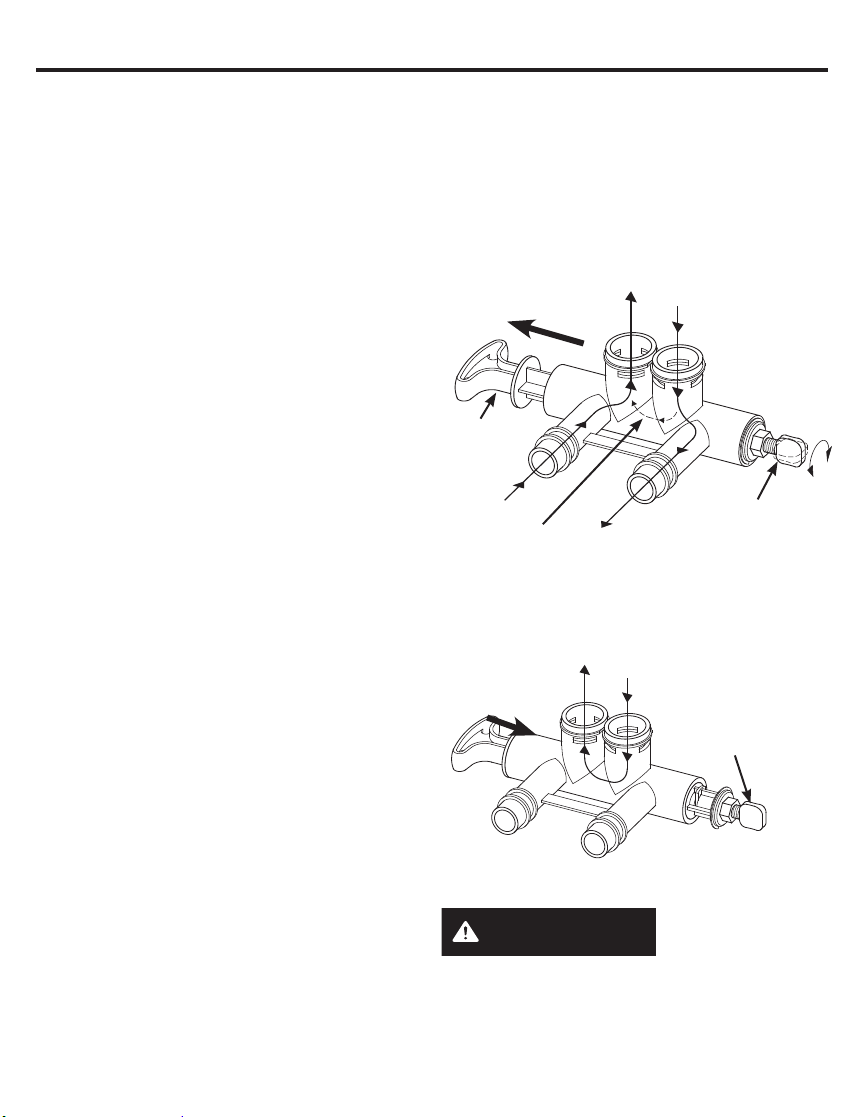
CLEANING THE NOZZLE AND VENTURI
ASSEMBLY
A clean nozzle and venturi is needed for the
water softening system to work properly.
This small unit makes the suction to move brine
from the salt storage area to the resin tank
during recharge. If it becomes plugged with
sand, dirt, etc., the water softening system will
not work and you will get hard water.
To get to the nozzle and venturi, remove the
water softening system top cover. Be sure the
water softening system is in service cycle (no
water pressure at nozzle and venturi). Then,
while holding the nozzle and venturi housing
with one hand, remove the cap. Lift out the
screen support and screen, then the nozzle
and venturi. Wash and rinse the parts in warm
water until clean. If needed, use a small brush
to remove iron or dirt. Also check and clean the
gasket.
NOTE: Some models have a small flow plug
located in the nozzle and venturi, and/or a
small cone shaped screen in the housing. Be
sure to check and clean these parts, if your
model is so equipped.
Carefully replace all parts in the correct order.
Lightly lubricate the o-ring seal with clean
silicone grease or petroleum jelly and place in
position. Install and tighten the cap, by hand
only. Do not overtighten the cap.
BREAKING A SALT BRIDGE
Sometimes, a hard crust or salt bridge forms
in the salt storage area. It is usually caused
by high humidity or the wrong kind of salt.
When the salt bridges, an empty space forms
between the water and salt. Then salt will not
dissolve in the water to make brine.
If the brine tank is full of salt, it is hard to tell if
you have a salt bridge. Salt is loose on top, but
the bridge is under it. The following is the best
way to check for a salt bridge.
Salt should be loose all the way to the bottom
of the tank. Take a broom handle or like tool,
and carefully push it down into the salt, working
it up and down. If the tool strikes a hard object
(be sure it’s not the bottom or sides of the tank),
it’s most likely a salt bridge. Carefully break the
bridge with the tool. Do not pound on the walls
of the tank.
To help dissolve the salt bridge pour
one gallon of warm water (not hot) into the tank.
If the wrong kind of salt made the bridge, take it
out. Then fill the tank with nugget or pellet salt
only. In humid areas, it is best to fill with less salt,
more often to prevent a salt bridge from forming.
Cap
O-ring seal
Screen support
Screen
*Flow plug
Nozzle and
Venturi
Gasket
*Flow plug
Ferrule Nut
Screen
IMPORTANT: Be sure small holes in the
gasket are centered directly over the small
holes in the nozzle and venturi housing.
* Install with numbered side up, concave side
down.
Push tool into salt
bridge to break
Ǝ±Ǝ
Pencil
mark
Broom
handle
27
Salt
bridge
Salt
Water
level
Page 28

Before you call for service
Troubleshooting Tips
Save time and money! Review the chart on this page first and you may not need to call for service.
NO SOFT WATER – Most Common Problems:
Check the following before calling for service:
• Not enough salt—should be at least 1/3 full.
• Bypass valve in “Bypass” position—handle should be in the “OUT” (service) position.
•
Hardness setting too low. Check hardness setting and adjust. Verify hardness of supply water—from
local water company, water test or call the GE Appliances Answer Center (800-952-5039 in US).
• Salt Bridge—salt solidifies above water level so that brine water is not in contact with salt. See
the Breaking a Salt Bridge section.
Problem Possible Cause What to do
No soft water Faucet or fixture where sample
was taken not plumbed to soft
water. NOTE: Be sure sample is
from a faucet that does not mix
soft and hard water. For example,
a single lever kitchen faucet, if the
cold side is plumbed to hard water.
No salt in the brine tank or salt
bridged
External power supply unplugged
at wall outlet or power cable to
softener not connected. Fuse
blown or circuit breaker popped
on circuit to electrical outlet.
Electrical outlet on a circuit that
can continuously be switched off
Manual bypass valve in bypass
position
Blending valve in open position • Turn blending valve clockwise to closed position.
Valve drain hose pinched,
plugged, elevated too high or
otherwise restricted
Nozzle and venturi dirty,
incorrectly assembled or
damaged
• To conserve salt, the installer may have isolated
some fixtures (outside faucets, toilets, etc.) from
soft water. From the outlet of the water softening
system, trace the water flow path in the house
plumbing. If soft water is not directed to a faucet or
fixture where wanted, consult a plumber.
• Check for a salt bridge or, if the tank is empty, refill
with recommended salt. Press (for 3 seconds) the
RECHARGE button to start an immediate recharge
and restore soft water supply.
• Check for a loss of electrical power to the water
softening system, due to any of these conditions
and correct as needed. With the power supply
restored, observe the faceplate time display and
read Programming the Control section. NOTE: the
electrical outlet for the softener should be live so it
cannot be accidentally switched off.
• Be sure the bypass valve stem is positioned
properly, with the handle in the OUT position.
• Any restriction in the drain hose may prevent proper
operation of the nozzle and venturi and reduce or
prevent brine draw during recharge.
• Refer to Cleaning the Nozzle and Venturi Assembly
instructions. With water pressure to the water
softening system off, take the nozzle assembly
apart. Inspect, clean and replace as needed. Any
foreign particle(s), scratches, nicks, etc. in the
passages can prevent operation. Be sure holes in
the gasket are centered over holes in the housing.
28
Page 29

Before you call for service
Problem Possible Cause What to do
Water hard
sometimes
Water feels
slippery after
installation of
water softener
Water Softener not
using any salt
Water is blue
color after water
softener was
installed
Water softener not
regenerating
Cloudiness
on glassware
(automatic
dishwashers)
Using hot water while the
water softening system is
regenerating
Control HARDNESS number
setting too low
Grains of hardness in your
water supply have increased
Absence of hardness minerals • This is normal. Hardness in water gives it the
Water softening system is a
“demand” unit
Possible salt bridge • See the Breaking a Salt Bridge section.
Possible plugged nozzle and
venturi
Acidic water in copper
plumbing
Meter turbine stuck • See the Manually Initiated Electronics
Sensor wire not plugged into
the control
No power to unit • Check the circuit breaker or fuses.
Mechanical defect • Call for service.
Combination of soft water and
too much detergent
• Avoid using hot water during water softening
system recharge because the water heater will
refill with hard water. See Automatic Hard Water
Bypass During Recharge section.
• Press MODE/SET button until arrow points to
HARDNESS. Be sure the number shown is the
same as the actual grains per gallon hardness of
your water supply. See Programming the Control
section if a change in setting is needed.
• Water hardness can change over time, especially
in well water. To check, have the water tested
by a water analysis laboratory or call your local
water department. Adjust the Hardness number
setting as needed.
abrasive feel you may have been accustomed to.
The slippery feel is the clean feel of soft water.
• See the Adjusting your Water Hardness section.
• Does not use much salt to regenerate - very
efficient.
• See the Cleaning the Nozzle and Venturi
Assembly section.
• Have the water tested at once.
Diagnostics section for troubleshooting
procedures.
• Call for service.
• See the Manually Initiated Electronics
Diagnostics section for troubleshooting
procedures.
• Call for service.
• This is called etching and is permanent. To
prevent this from happening, use less detergent
if you have soft water. Wash glassware in the
shortest cycle that will get them clean.
29
Page 30

Before you call for service
Problem Possible Cause What to do
Excessive/high
level of water in
brine tank
Salty tasting or
brown/yellow
colored water
after installation
Brown/yellow
colored water
Resin beads
showing up in
drinking water
Sounds you
might hear
Water has air
bubbles and is
cloudy
Blue light
Flashing
When power
applied to the
system
If “DAYS TO
EMPTY” is
flashing
Valve drain hose pinched,
plugged, elevated too high or
otherwise restricted
Drain lines connected together • Separate drain lines.
Nozzle and venturi dirty,
incorrectly assembled or
damaged.
Unit not sanitized • Complete Sanitization Procedures.
Low water pressure Check pressure:
Restricted drain hose • Clean and reconnect hose.
Unit was idle for a period of time • Complete the Sanitization Procedures.
Cracked distributor or unit
plumbed backwards
Running water from the unit into
a drain during recharge
Air in system after installation • Will go away after it runs for a while.
Control needs to be programmed
(a power outage may have
occurred)
Low salt level, less than 15 days • Fill with salt.
• A restriction in this drain hose may prevent
proper operation of the nozzle and venturi and
reduce or prevent brine draw during recharge.
• Refer to Cleaning the Nozzle and Venturi
Assembly instructions. With water pressure to
the water softening system off, take the nozzle
assembly apart. Inspect, clean and replace as
needed. Any foreign particle(s), scratches, nicks,
etc. in the passages can prevent operation. Be
sure holes in the gasket are centered over holes
in the housing
• At completion of recharge cycle (approx. 2
hours), run water from faucets to purge the salty
water.
• Drain height 8’ or less, pressure should be
minimum 20 psi.
• Drain height above 8’, pressure should be
minimum 50 psi.
• Check for kinks in drain line
• Check softener “IN & OUT” plumbing is correct.
• Call for service.
• This is normal.
• See the Programming the Control section.
• Reset salt level.
30
Page 31

Before you call for service
Problem Possible Cause What to do
Error Codes 1,3,4,5
on Control
Error Codes 6,7,8 on
Control
If “Err” in display Electrical problem with
Wiring may have worked
loose in the control
Issue with Water Shutoff
valve
system
• Unplug external power supply.
• Remove control cover, release clips on side.
• Check for loose/incorrect wiring connections to electronic board
or switch. Reconnect as required.
• Reassemble control cover.
• Plug in Transformer.
• Wait 8 minutes for Error Code to reappear.
• If error Code reappears, call for service.
• Unplug external power supply.
• Replace the water Shutoff valve.
• Check for loose/incorrect wiring connections to electronic board.
Reconnect as required.
• Reassemble control cover.
• Plug in Transformer.
– When the Error 6,7 or 8 is displayed, press and hold the
Recharge button for 5 seconds.
• Wait 2 minutes for Error Code to reappear.
• If error Code reappears, call for service.
• Call for service.
Advanced troubleshooting for service
AUTOMATIC ELECTRONIC
DIAGNOSTICS
This water softener has a
self-diagnostic function for the
electrical system (except into
power and/or water meter).
The water softener monitors
electronic components and
circuits for correct operation. If a malfunction
occurs, an error code appears in the display.
While an error code appears in the display, all
buttons are inoperable except the MODE/SET
button. MODE/SET remains operational so the
service person can perform the Manual Advanced
Diagnostics, see below, to further isolate the
problem.
Procedure for removing error code from
display:
1. Unplug transformer from electrical outlet.
2. Correct problem.
3. Plug in transformer.
4. Wait 8 minutes. The error code will return if the
problem was not corrected.
MANUAL INITIATED ELECTRONIC
DIAGNOSTICS
Use the following procedures to advance the
water softener through the regeneration cycles to
check operation.
Call for Service
Figure 18
Lift off the Salt Hole Cover, remove the top cover
by unlocking the tabs in the back and rocking
forward, to observe cam and switch operation
during valve rotation.
1. Press and hold MODE/SET for 3 seconds until
the Set low salt alarm display appears, next
press the MODE/SET button two addition times
until “000” shows in the display, then release,
see Figure 15.
2. The 3 digits indicated water meter operation
as follows: If you don’t get a reading on the
display, with faucet open, pull the sensor from
the valve outlet port. Pass a small magnet back
and forth in front of the sensor. You should get
a reading in the display. If you get a reading,
shut off water supply, unhook the in and out
plumbing and check the turbine for binding.
Motor
Position
switch
Valve
outlet
Sensor
housing
Turbine
Turbine
support and
shaft
31
Page 32

Advanced troubleshooting for service
MANUAL INITIATED ELECTRONIC DIAGNOSTICS
3. Symbols in the display indicate POSITION
switch operation, (see Figure 19).
Switch is open Switch is closed
Water Meter
Figure 19
6. Press and hold the MODE/SET button until
the mode code (H40 for GXSHC40N) shows
in the display (see Figure 20). This code
identifies the softener mode. If an incorrect
model code is displayed, the softener will
operate on incorrect configurations data.
7. To change the code number, press the
4. Use RECHARGE button to manually
advance the valve into each cycle and
check correct switch operation. NOTE: Be
sure water is in contact with salt, and not
separated by a salt bridge (see Breaking a
Salt Bridge section).
5. While in this diagnostic screen, the
following information is available and may
be beneficial for various reasons. This
information is retained by the computer from
the first time electrical power is applied to
the electronic controller.
a. Press the
number of days this electronic control has
had electrical power applied.
b. Press the
number of regenerations initiated by the
electronic control since the code number
was entered.
UP button to display the
DOWN button to display the
Figure 20
UP or DOWN button until the correct
code shows.
8. To return to the present time display, press
the MODE/SET button.
9. Press the MODE/SET button to return to
the present time display. If the code was
changed, make all the timer setting.
NOTE: If the control is left in a diagnostic
display or a flashing display when
setting times or hardness, present time
automatically returns if a button is not
pressed within four minutes.
32
Page 33

Advanced troubleshooting for service
Service: Manually Advance Recharge Check
NOTE: The control display must show a steady
time (not flashing).
1. Press the RECHARGE button and hold in for
three seconds. RECHARGE
as the water softening system enters the
fill cycle of recharge. Remove the brinewell
cover and, using a flashlight, observe fill
water entering the brine tank. If water does
not enter the tank, look for an obstructed
nozzle, venturi, fill flow plug or brine tubing.
See Care and Cleaning of the Water
Softener System section.
2. After observing fill, press the RECHARGE
button to move the water softening system
into brining. A slow flow of water to the drain
will begin. Verify brine draw from the brine
tank by shining a flashlight into the brinewell
and observing a noticeable drop in the liquid
level over an extended period of time (is to
20 minutes).
NOTE: Be sure a salt bridge is not preventing
water from contacting salt. See Care and
cleaning of the water softening system section.
If the water softening system does not draw
brine, check:
nozzle and/or venturi dirty or defective.
defective nozzle and venturi seal.
nozzle and venturi not seated properly
on gasket.
other inner valve defect (rotor seal, rotor
and disc, wave washer, etc.).
restricted drain (check drain fitting and
hose).
NOTE: If water system pressure is low, an
elevated drain hose may cause back pressure,
stopping brine draw.
3. Again, press the RECHARGE button to
move the water softening system into
backwash. Look for a fast flow of water
from the drain hose. A slow flow indicates a
plugged top distributor, backwash flow plug
or drain hose.
begins to flash
4. Press the RECHARGE button to move the
water softening system into fast rinse. Again
look for a fast drain flow. Allow the water
softening system to rinse for a few minutes
to flush out any brine that may remain in the
resin tank from the brining cycle test.
5. To return the water softening system to
service, press the RECHARGE button.
Cam
Figure 21
Valve Positions:
Position Function
S Service
F Fill
BR Brine Fill
BW Back Wash
R Rinse
Position Markers
(valve in service)
Motor
33
Page 34

Exploded View
11
4
12
41
16
17
19
40
146
42
3
7
13
56
5
2
999
6
29
23
8
7
6
5
20
22
23
56
8
10
24
30
9
26
34
Page 35

Exploded View
141
139
109
110
111
112
113
114
116
115
117
124
118 120
101
103
105
Wear Strip
Seal
Cross-section
146
106
View
119
130
130
122
107
125
123
130
108
130
137
138
148
136/140
145
148
132
153
143
152
151
152
121
35
Page 36

Parts List
Reference
No.
0002 WS31X10051 BACK COVER, ELECTRONICS 1
0003 WS35X10001 O-RING SEAL KIT 1
0004 WS35X21986 DECAL, FACEPLATE 1
0005 WS07X10004 HOSE, DRAIN, 20 FT. 1
0006 WS31X10044 FILTER SCREEN 1
0007 WS14X10002 DISTRIBUTOR, TOP 1
0008 WS14X10005 DISTRIBUTOR, BOTTOM 1
0009 WS01X10002 RESIN, 1 CU. FT. 1
0010 WS32X10011 TANK, RESIN, 9 X 40 1
0011 WS31X10052 COVER, TOP 1
0012 WS34X10021 FACEPLATE 1
0013 WS35X21984 MAIN CONTROL BOARD KIT 1
0016 WS26X22083 EXTERNAL POWER SUPPLY WITH POWER CORD 1
0017 WS31X10053 COVER, SALT HOLE WITH LABELS 1
0019 WS33X21987 RIM 1
0020 WS33X10024 COVER, BRINEWELL 1
0022 WS34X10025 BRIN EWELL 1
0023 WS02X10088 SCREW KIT, BRINE TANK 1
0024 WS32X10032 TANK, BRINE 1
0026 WS22X10063 OVERFLOW ADAPTER KIT 1
0029 WS15X10077 BRINE VALVE ASM. 1
0030 WS35X10063 FLOAT, STEM & GUIDE 1
0040 WS35X21981 WIFI MODULE KIT 1
0041 WS01X21982 HOLDER, WIFI MODULE 1
0042 WS21X21983 CABLE ASM., WIFI MODULE 1
0056 WS28X10078 TANK NECK CLAMP KIT 1
0101 WS02X10023 SCREW, #4-24 X 3/4” 2
0103 WS31X10003 SWITCH 1
0105 WS02X10024 SCREW, #10 X 2-5/8” 8
0106 WS31X10013 COVER, VALVE 1
0107 WS03X10034 WASHER. WAVE 1
0108 WS26X10010 ROTOR & DISC ASM. 1
0109 WS19X10010
GE Appliances
Part. No
Part Description Quantity
CAP 1
GXSHC40N
36
Page 37

Parts List
Reference
No.
0110 WS03X10011 SEAL, O-RING, 1.125 X 1.37 1
0111 WS19X10005 SUPPORT, SCREEN 1
0112 WS03X10013 SCREEN 1
0113 WS22X10036 FLOW PLUG, .15 GPM 1
0114 WS08X10008 GASKET, NOZZLENENTURI 1
0115 WS03X10073 CONE SCREEN 1
0116 WS22X10021 PLUG, FILL FLOW, .30 GPM 1
0117 WS03X10017 NUT, FERRULE 1
0118 WS15X10034 NOZZLENENTURI BODY 1
0119 WS03X10018 RETAINER 1
0120 WS03X10019 SEAL, O-RING, 1/4" X 3/8" 2
0121 WS15X10025 BODY, VALVE 1
0122 WS03X10020 SPRING 1
0123 WS22X10029 PLUG, DRAIN SEAL 1
0124 WS15X10046 NOZZLENENTURI ASM. 1
0125 WS03X10043 WAVE SPRING BEARING 1
0130 WS35X10020 SEAL KIT 1
0132 WS22X10065 DRAIN HOSE ADAPTER KIT 1
0136/140 WS26X21821 MOTOR, CAM & GEAR KIT, 1" 1
0137 WS26X10009 BEARING 1
0138 WS26X10023 PLATE, MOTOR 1
0139 WS02X10028 SCREW, #6-20 X 3/8" 3
0141 WS02X10058 SCREW, #8-32 X 1" 2
0143 WS60X10011 ADAPTER, NPT THREAD, 1" VALVE 2
0145 WS60X10008 CLIP 4
0146 WS28X10018 WIRE HARNESS, SENSOR ASM 1
0148 WS26X10030 TURBINE & SUPPORT ASSEMBLY* 1
0151 WS15X10078 BYPASS ASM 1
0152 WS03X10072 SEAL, O-RING 4
0153 WS15X21985 WATER SHUTOFF VALVE 1
0998 WS35X10065 INSTALLATION KIT 1
0999 Manual Online OWNER’S MANUAL 1
GE Appliances
Part. No
Part Description Quantity
GXSHC40N
* Includes 2 each of REF. NO. 145 (CLIP) & REF. NO. 152 (O-RING)
37
Page 38

Water Softening System Limited Warranty
All warranty service provided by our Factory Service Centers or an authorized technician. For
service, call toll free 1-800-952-5039. Please have serial number and model number availa ble
when calling for service.
(For Customers in the U.S.)
For The Period Of: We Will Replace:
One Year
From the date of the
original purchase
Three Years
From the date of the
original purchase
Ten Years
From the date of the
original purchase
Any part of the Water Softening System which fails due to defect in
materials or workmanship. During this limited one-year warranty,
GE Appliances will also provide, free of charge, all labor and related
service to replace the defective part.
The electronic monitor, if it fails due to a defect in materials or
workmanship. During this three-year limited warranty, you will be
responsible for any labor or related service cost.
A replacement resin tank, if it fails due to defect in materials or
workmanship. During this ten-year limited warranty, you will be
responsible for any labor or related service costs.
What Is Not Covered:
Service trips to your home to teach you how
to use the product.
Improper installation, delivery or
maintenance.
Failure of the product if it is abused,
misused, altered, used commercially or
used for other than the intended purpose.
Use of this product where water is
microbiologically unsafe or of unknown
quality, without adequate disinfection before
or after the system.
Replacement of house fuses or resetting of
circuit breakers.
EXCLUSION OF IMPLIED WARRANTIES—Your sole and exclusive remedy is product
repair as provided in this Limited Warranty. Any implied warranties, including the implied
warranties of merchantability or fitness for a particular purpose, are limited to one year
or the shortest period allowed by law.
This limited warranty is extended to the original purchaser for products purchased for home use
within the USA. If the product is located in an area where service by a GE Appliances Authorized
Servicer is not available, you may be responsible for a trip charge or you may be required to bring
the product to an Authorized GE Appliances Service location for service. In Alaska, the limited
warranty excludes the cost of shipping or service calls to your home.
Some states do not allow the exclusion or limitation of incidental or consequential damages. This
limited warranty gives you specific legal rights, and you may also have other rights which vary
from state to state. To know what your legal rights are, consult your local or state consumer affairs
office or your state’s Attorney General.
Warrantor: GE Appliances, a Haier company, Louisville, KY 40225
Damage to the product caused by accident,
fire, floods or acts of God.
Incidental or consequential damage caused
by possible defects with this appliance, its
installation or repair.
Product not accessible to provide required
service.
If this appliance is used for other than
private family use, the parts, electronic
monitor, and resin tank warranty applies for
only 90 days from the date of purchase.
38
Page 39

Water Softening System Limited Warranty (For Customers in the Canada)
All warranty service provided by our Factory Service Centers or an authorized technician. For
service, call toll free 1-866-777-7627. Please have serial number and model number availa ble
when calling for service.
For The Period Of: We Will Replace:
One Year
From the date of the
original purchase
Three Years
From the date of the
original purchase
Ten Years
From the date of the
original purchase
What Is Not Covered:
Any part of the Water Softening System which fails due to defect in
materials or workmanship. During this limited one-year warranty,
GE Appliances will also provide, free of charge, all labor and related
service to replace the defective part.
The electronic monitor, if it fails due to a defect in materials or
workmanship. During this three-year limited warranty, you will be
responsible for any labor or related service cost.
A replacement resin tank, if it fails fails due to defect in materials
or workmanship. During this ten-year limited warranty, you will be
responsible for any labor or related service costs.
Service trips to your home to teach you how
to use the product.
Improper installation, delivery or
maintenance.
Failure of the product if it is abused,
misused, altered, used commercially or
used for other than the intended purpose.
Use of this product where water is
microbiologically unsafe or of unknown
quality, without adequate disinfection before
or after the system.
Replacement of house fuses or resetting of
circuit breakers.
EXCLUSION OF IMPLIED WARRANTIES—Your sole and exclusive remedy is product
repair as provided in this Limited Warranty. Any implied warranties, including the implied
warranties of merchantability or fitness for a particular purpose, are limited to one year
or the shortest period allowed by law.
This limited warranty is extended to the original purchaser for products purchased for home
use within Canada. In-home warranty service will be provided in areas where it is available and
deemed reasonable by Mabe to provide.
WARRANTOR IS NOT RESPONSIBLE FOR CONSE QUEN TIAL DAMAGES.
Warrantor: MABE CANADA INC
Damage to the product caused by accident,
fire, floods or acts of God.
Incidental or consequential damage caused
by possible defects with this appliance, its
installation or repair.
Product not accessible to provide required
service.
If this appliance is used for other than
private family use, the parts, electronic
monitor, and resin tank warranty applies for
only 90 days from the date of purchase.
.
39
Page 40

For Iowa Use Only
FOR IOWA USE ONLY
All sales in Iowa require the following signature before consummation of sale. These signatures
must be retained by seller/renter for 2 years minimum.
Buyer/Renter
Seller ____________________________________________________ Date _______________
Seller’s Address ________________________________________________________________
Seller’s Phone No. ______________________________________________________________
______________________________________________ Date _______________
Model GXSHC40N
40
Page 41

Notes
41
Page 42

Consumer Support
GE Appliances Website
Have a question or need assistance with your appliance? Try the GE Appliances Website 24
hours a day, any day of the year! You can also shop for more great GE Appliances products and
take advantage of all our on-line support services designed for your convenience.
In the US: GEAppliances.com
Register Your Appliance
Register your new appliance on-line at your convenience! Timely product registration will allow for
enhanced communication and prompt service under the terms of your warranty, should the need
arise. You may also mail in the pre-printed registration card included in the packing material.
In the US: GEAppliances.com/register
Schedule Service
Expert GE Appliances repair service is only one step away from your door. Get on-line and
schedule your service at your convenience any day of the year.
In the US: GEAppliances.com/service or call 800.432.2737 during normal business hours.
Extended Warranties
Purchase a GE Appliances extended warranty and learn about special discounts that are available
while your warranty is still in effect. You can purchase it on-line anytime. GE Appliances Services
will still be there after your warranty expires. In the US: GEAppliances.com/extended-warranty
or call 800.626.2224 during normal business hours.
Parts and Accessories
Individuals qualified to service their own appliances can have parts or accessories sent directly
to their homes (VISA, MasterCard and Discover cards are accepted). Order on-line today 24
hours every day. In the US: GEApplianceparts.com or by phone at 877.959.8688 during normal
business hours.
Instructions contained in this manual cover procedures to be performed by any user. Other
servicing generally should be referred to qualified service personnel. Caution must be
exercised, since improper servicing may cause unsafe operation.
Contact Us
If you are not satisfied with the service you receive from GE Appliances, contact us on our
Website with all the details including your phone number, or write to:
In the US:
General Manager, Customer Relations | GE Appliances, Appliance Park | Louisville, KY 40225
GEAppliances.com/contact
42
Page 43

Información sobre Seguridad . . . 44
Especificaciones y Dimensiones 45
Acerca del Suavizante .........46
Antes de Comenzar ...........49
Requisitos de Instalación ......50
Instrucciones de Instalación .... 53
Programación del Suavizante . . 60
Cuidado y Limpieza ........... 67
Rutina de Mantenimiento ......69
Antes de solicitar el servicio
técnico
.....................70
Vista Ampliada/ Listado
de Piezas ................... 76
Garantía (EE.UU.) .............80
Garantía (Canadá) .............81
Soporte para el Consumidor . . . 84
Sistemas evaluados y certificados por NSF International
contra NSF/ANSI Estándar 44 para los reclamos sobre
reducción de químicos especificados en la página 43, y
certificados para NSF/ANSI 372.
Sistema probado y certificado por Water Quality
Association en cumplimiento con CSA B483.1.
Ante cualquier duda o preocupación sobre la instalación y
mantenimiento del suavizante de agua, comuníquese a nuestro número
gratuito al 800-952-5039 (US) o 866-777-7627 (Canadá), o visite
geappliances.com. Al llamar, tenga a mano los números de modelo
y de serie de su producto. Esta información se puede encontrar en la
calcomanía de calificación ubicada en el borde debajo de la tapa de la sal.
GE es una marca registrada de General Electric Company. Fabricado bajo licencia de marca.
Page 44

INFORMACIÓN IMPORTANTE DE SEGURIDAD.
LEA TODAS LAS INSTRUCCIONES ANTES DEL USO
PRECAUCIONES DE SEGURIDAD
ADVERTENCIA
Por su seguridad, se debe seguir la información en este manual
con el fin de reducir el riesgo de una descarga eléctrica, daños a
la propiedad o daños personales.
ADVERTENCIA
cobre o galvanizada de agua fría podría usarse para
conectar a tierra los tomacorrientes eléctricos en la
casa. No mantener esta conexión a tierra podría
resultar en descargas eléctricas peligrosas. Si la
tubería de agua fría es usada para conectar a tierra
los tomacorrientes, por favor refiérase a la sección de
Cómo instalar el cable a tierra antes de cortar la
tubería.
Revise y cumpla con todos los códigos estatales y
locales. Observe las pautas aquí presentadas.
Tenga cuidado al manipular el sistema de
descalcificación de agua. No lo voltee, deje caer,
arrastre o coloque en protuberancias extremas.
Los sistemas de descalcificación de agua que
utilicen cloruro de sodio (sal) para la recarga
agregan sodio al agua. Las personas que siguen
dietas con restricciones de sodio deben considerar
el sodio adicional como parte de su consumo
general. El cloruro de potasio puede servir como
una alternativa para el cloruro de sodio de su
descalcificador.
Use sólo soldadoras y fundiciones libres de plomo
y para todas las conexiones con estaño, de
acuerdo con lo requerido por los códigos estatales
y federales.
Este sistema suavizante de agua se deberá
instalar y ubicar de acuerdo con las Instrucciones
de Instalación antes de ser usado.
ADVERTENCIA
segura a nivel microbiológico o que sea de calidad
desconocida sin una desinfección adecuada, antes o
después, del sistema.
In the state of California: You must turn the Salt
Efficiency Feature setting to ON. This may initiate
more frequent recharges. However it will operate at
4,000 grains per pound of salt or higher. To turn on
the Salt Efficiency Feature, follow the instructions
in the “Salt Saver” section of this manual
Una tubería de
No usar con
agua que no sea
ADVERTENCIA
las piezas sin uso y materiales de embalaje luego de
la instalación. Las pequeñas partes restantes luego
de la instalación podrían ocasionar riesgo de
obstrucción.
El sistema de descalcificación de agua funciona
solamente con 24 voltios-60 Hz. Cerciórese de
usar exclusivamente el transformador incluido.
El transformador se debe conectar únicamente
a un tomacorriente interior con conexión a tierra
de 120 voltios.
Utilice únicamente sales para descalcificación
del agua, al menos con 99,5% de pureza. Se
recomiendan las sales en PEPITAS, BOLITAS o
SAL GRUESA SOLAR. No utilice sales en roca,
bloque, granuladas o sales para la elaboración
de helados. Éstas pueden contener suciedad
y sedimentos, o pasta y masa y podrían crear
problemas de mantenimiento.
Mantenga la tapa del orificio de la sal en su lugar
en el descalcificador a menos que esté realizando
mantenimiento o reponiendo la sal. Estos tipos de
sales pueden contener suciedad y sedimentos que
pueden crear empaste o apelmazamiento, creando
problemas de mantenimiento para el ablandador
de agua.
Evite instalar directamente en contacto con la luz
solar. El exceso de calor solar puede ocasionar
distorsión y otros daños sobre partes no metálicas.
Si el ablandador de agua es instalado al aire
libre, no lo coloque en una ubicación donde esté
expuesto a climas húmedos, en contacto directo
con la luz solar, temperaturas extremas de calor o
frío, u otras formas de abuso
In the Commonwealth of Massachusetts, Plumbing
Code 248 CMR shall be adhered to. Consult with
your licensed plumber.
Descarte todas
LEA Y GUARDE ESTAS INSTRUCCIONES
44
Page 45

Reclamos por Especificaciones y Funcionamiento
Este modelo cuenta con una calificación de eficiencia. El índice de eficiencia es válido sólo con la dosis de sal
mínima indicada. El suavizante cuenta con la función de regeneración de demanda iniciada (demand initiated
regeneration, D.I.R.), que cumple con las especificaciones de funcionamiento para minimizar la cantidad de
salmuera regenerante y agua usada en esta operación.
El suavizante cuenta con una eficacia de la sal evaluada de no menos de 4,000 granos del total de
intercambio de dureza por libra de sal (en base al cloruro de sodio), y no brindará más sal que la evaluada
ni será operado en un índice de flujo de servicio máximo sostenido superior al evaluado. Se probó que este
suavizante brinda agua suave durante por lo menos diez minutos en forma continua en el índice de flujo de
servicio evaluado. La eficacia de la sal evaluada es medida por evaluaciones de laboratorio descriptas en el
Estándar 44 de NSF/ANSI. Estas evaluaciones representan el máximo nivel de eficacia posible que el sistema
puede alcanzar. La eficacia operativa es la eficacia real luego de que el sistema fue instalado. Es típicamente
inferior a la eficacia, debido a los factores de aplicación individual que incluyen la dureza del agua, el uso del
agua, y otros contaminantes que reducen la capacidad del suavizante.
Especificaciones
Modelo GXSHC40N
Capacidad Evaluada* (Granos por Dosis de Sal) 11,700 @ 2.3 lbs
Eficacia Evaluada** (Granos/ Libras de Sal en Dosis de Sal Mínima) 5,100 @ 2.3 lbs.
Agua usada durante la Regeneración (galones/ granos) 2.7 /1000
Agua Total Usada por Regeneración en Dosis de Sal Mínima 37.0 gallons
Cantidad de Resina de Intercambio Iónico de Alta Capacidad (lb./ pies
cúbicos).
Tamaño Nominal del Tanque de Resina (pulg., diám. x altura) 9 x 40
Índice de Flujo del Servicio (gpm) 9.5
Caída de Presión en Flujo del Servicio Evaluado (psig) 12.7
Dureza Máxima del Suministro de Agua (gpg) 110
Hierro Máximo en Agua Pura del Suministro de Agua (ppm)*** 8
Límites de Presión del Agua (psi mínimo- máximo)**** 20-125
Límites de Temperatura del Agua (mín.- máx.ºF) 40-120
Índice de Flujo Máximo al Drenaje (gpm) 2.3
Estos sistemas cumplen con los reclamos de
capacidad específica de NSF/ANSI 44, de acuerdo
con los verificado y corroborado por datos de
evaluaciones.
* La evaluación fue realizada utilizando cloruro de
sodio con grados de bolitas de la sal regenerante.
** El índice de eficiencia es válido sólo con la dosis de
sal mínima indicada. La eficacia de estos suavizantes
fue evaluada de acuerdo con NSF/ANSI 44.
*** La extension de la eliminación del hierro puede
variar con las condiciones. La capacidad de reducir
el hierro del agua pura es corroborada por datos
evaluados de WQA. El Estado de Wisconsin requiere
tratamientos adicionales si el suministro de agua contiene un nivel superior a 5 ppm de hierro en agua pura.
Consulte la sección Limpieza del Hierro con el Sistema Suavizante de Agua.
**** Límites de presión en Canadá. 1.4–7.0 kg/cm2.
Contaminante
Bario 10 ±10% mg/L 2.0 mg/L
Radio 226/228 25 pCi/L 5pCi/L
Los parámetros de la evaluación incluyen: pH = 7.5±0.5, índice
de flujo = 7.5 gpm y presión dinámica = 35±5 psig
45
31,500 @ 8.7 lbs.
40,000 @ 15.1 lbs.
57.56/1.11
Reclamos de Funcionamiento
Nivel de
Desafío
del Agua
Prefiltrada
Nivel Máximo de
Agua Permitida
Page 46

Sobre el sistema de descalcificación de agua
SERVICIO
Cuando el sistema descalcificador de agua está
proporcionando agua descalcificada, a esto se le
llama “Servicio”. Durante el servicio, el agua dura
fluye desde la tubería de agua principal de la casa
hacia el sistema de descalcificación de agua. En
el interior del tanque de resina del sistema de
descalcificación de agua hay una película o capa
compuesta de miles de resinas plásticas diminutas.
Cuando el agua dura pasa a través de la capa, cada
resina diminuta atrapa los minerales duros. A esto se
le llama intercambio de iones. Es como un imán que
atrae y atrapa metales. Luego, el agua sin minerales
duros (agua descalcificada o agua blanda) fluye
hacia la casa desde el sistema de descalcificación.
CIRCUNVALACIÓN AUTOMÁTICA DEL AGUA DURA DURANTE LA RECARGA
Durante la recarga, el suavizante de agua se coloca
automáticamente en el modo de tubo de desviación,
permitiendo que el agua dura esté disponible en el
hogar. Una vez que el suavizante es recargado, el
agua es dirigida nuevamente a través del suavizante
para sea acondicionada.
Después de un período de tiempo, la capa de resina
se obstruye o se satura con los minerales duros y
debe limpiarse. Esta limpieza se denomina recarga.
La recarga comienza a las 2:00 AM (ajustado en
fábrica) por el control del sistema de descalcificación
de agua, y consiste en cinco etapas o ciclos. Éstas
son FILL (llenado), BRINING (proceso de salado),
BRINE RINSE (enjuague salado), BACKWASH
(lavado regresivo) y FAST RINSE (lavado rápido).
Sin embargo, se debe evitar el uso de agua
CALIENTE debido a que el calentador de agua
se llenará con el agua dura. Espere hasta que el
ciclo de recarga esté completo antes de usar el
agua caliente en su hogar.
LLENADO
La sal disuelta en agua es llamada salmuera. La
salmuera es necesaria para limpiar los minerales
duros de las diminutas partículas de resina. Para
formar la salmuera, el agua fluye hacia el interior del
tanque de sal durante el período de llenado.
SALADO
Durante el proceso de salado, la salmuera se
desplaza del área del tanque de almacenamiento
de la sal hacia el tanque de la resina. La salmuera
es el agente de limpieza necesario para remover los
minerales duros de la capa de resina. Los minerales
duros y la salmuera son descargados hacia el
desagüe.
La boquilla y el Venturi crean una succión para
mover la salmuera, manteniendo un ritmo muy bajo
para obtener la resina de limpieza con la menor
cantidad de sal.
ENJUAGUE DE SALMUERA
Después de que se use una cantidad de salmuera
medida con anterioridad, la válvula de salmuera
se cierra. El agua continúa fluyendo en la misma
trayectoria que durante el proceso de salado,
excepto por el flujo de salmuera discontinuado. Los
minerales duros y la salmuera fluyen del tanque de
resina hacia el desagüe.
LAVADO REGRESIVO
Durante el lavado regresivo, el agua viaja hacia
arriba a través del tanque de resina a un flujo de
ritmo rápido, purgando el hierro acumulado, la
suciedad, y los sedimentos desde la capa de resina
hacia el desagüe.
ENJUAGUE RÁPIDO
El lavado regresivo es seguido por un flujo de agua
rápido hacia abajo a través del tanque de resina. El
flujo rápido purga la salmuera del fondo del tanque, y
rellena el tanque de resina.
A continuación del enjuague rápido, el sistema de
descalcificación de agua regresa al servicio de agua
descalcificada.
46
Page 47

Sobre el sistema de descalcificación de agua
FUNCIONAMIENTO NORMAL, PANTALLAS DE CONTROL
Durante el funcionamiento normal, la hora actual del
día y AM o PM y DAYS TO EMPTY (DÍAS HASTA
VACIARSE) aparecen en el área de la pantalla de
control.
FUNCIÓN: CONTROLES OPCIONALES DE RECARGADO
A veces, es posible que usted desee o necesite una
recarga iniciada manualmente. Dos ejemplos:
Usted ha usado más agua que de costumbre
(huéspedes en la casa, lavado adicional, etc.) y
quizás se quede sin agua descalcificada antes de
la próxima recarga.
Se le acabó la sal al sistema.
Use una de las funciones siguientes para comenzar
una recarga inmediatamente, o en el próximo inicio
de recarga preprogramada.
FUNCIÓN: MEMORIA
Si el suministro eléctrico del sistema de
descalcificación de agua es interrumpido, la pantalla
de control estará en blanco, y la luz indicadora
azul se apaga, pero el control mantiene la hora
correcta por seis horas aproximadamente. Cuando el
suministro es restaurado, usted tendrá que reajustar
la hora actual solamente si la visualización y la
luz indicadora azul están intermitentes. Todos los
otros ajustes se mantienen y nunca requieren ser
ajustados a no ser que usted desee hacer algún
cambio.
El sistema se recargará de forma automática en el
tiempo de recarga presente, según sea necesario.
RECARGAR ESTA NOCHE
Presione (sin mantener presionado) el botón
RECHARGE (Recargar). RECHARGE TONIGHT
(Recargar Esta Noche) titila en el área de la pantalla
de control. Se realizará una recarga en el próximo
tiempo de inicio de recarga presente. Si decide
cancelar esta recarga, presione el mismo botón una
vez más.
RECARGAR AHORA
Mantenga presionado el botón RECHARGE
(Recargar) hasta que RECHARGE NOW (Recargar
Ahora) comience a titilar en el área de la pantalla
de control. El sistema suavizante de agua inicia una
recarga de inmediato y, al finalizar en unas dos horas,
contará con un nuevo suministro de agua suave. Una
vez iniciada, ya no podrá cancelar esta recarga.
Si la hora está intermitente después de una
interrupción prolongada en el suministro eléctrico,
el sistema de descalcificación de agua continúa
operando como debería para proporcionarle agua
descalcificada. Sin embargo, la recarga podrían
ocurrir a la hora equivocada del día hasta que usted
reajuste el control a la hora correcta del día.
CARACTERÍSTICA/SERVICIO: DIAGNÓSTICO ELECTRÓNICO AUTOMÁTICO
La computadora de control tiene una función de
diagnóstico automático para el sistema eléctrico
(excepto para la energía de entrada y la medición del
agua). La computadora monitorea
los componentes electrónicos y los circuitos para una
operación correcta. Si ocurre un error, un código de
error aparece en la pantalla de control.
47
Page 48

Sobre el sistema de descalcificación de agua
INFORMACIÓN SOBRE LA CONDICIÓN DEL AGUA
HIERRO
El hierro del agua puede causar manchas en la ropa
y accesorios de plomería. Puede alterar de forma
negativa el sabor de la comida, el agua potable y
otras bebidas. El hierro del agua es medido en
partes por millón (ppm). El ppm de hierro total*, y
el tipo o tipos* es determinado a través de análisis
químicos. Los cuatro tipos de hierro diferentes en el
agua son:
Hierro ferroso (agua potable)
Hierro férrico (agua roja)
Hierro asociado por bacterias y organismos
Hierro asociado en forma coloide e inorgánica
(ferroso o férrico)
El hierro ferroso (agua potable) es soluble y se
disuelve en agua. Este suavizante de agua reducirá
cantidades moderadas de este tipo de hierro (lea las
especificaciones). **El hierro ferroso (agua potable)
normalmente se detecta tomando un ejemplo del
agua en una botella o vaso limpios. Inmediatamente
luego de tomarlos, el ejemplo es claro. A medida
que el ejemplo de agua se asienta, gradualmente se
enturbia y se vuelve levemente amarilla o marrón a
medida que el aire oxida el hierro. Este normalmente
ocurre entre los 15 y 30 minutos.
Al usar el suavizante para reducir el hierro ferroso
(agua potable), agregue 5 granos a la configuración
dura por cada 1 ppm de hierro ferroso (agua
potable). Lea la sección “Configuración del Número
de Agua Dura).
Los hierros férricos (agua roja), y asociados
con bacterias y organismos son insolubles. Este
suavizante de agua no eliminará el hierro férrico
ni las bacterias. Este hierro es visible de forma
inmediata al salir por un grifo, ya que se oxidó antes
de llegar al hogar. Aparece en forma de pequeñas
partículas turbias suspendidas de color amarillo,
anaranjado o rojizo. Una vez que el agua se asentó
por un período de tiempo, las partículas quedan en
el fondo del envase. Generalmente, estos hierros
son eliminados del agua a través del proceso de
filtración. También se recomienda la cloración con el
hierro con bacterias.
El hierro asociado en forma coloide o inorgánico
es de forma férrica o ferrosa que no se filtrará ni
intercambiará fuera del agua. Este suavizante de
agua no eliminará el hierro coloidal. En algunas
instancias, el tratamiento puede mejorar el agua
con hierro coloidal. Normalmente, el agua con hierro
coloidal cuenta con un aspecto amarillento al ser
extraído. Luego de asentarse durante varias horas,
el color persiste y el hierro no se asienta, sino que
permanece suspendido en el agua.
SEDIMENTO
El sedimento son partículas de material fino y extraño
suspendidas en el agua. Este suavizante de agua
no eliminará el sedimento. Con gran frecuencia este
material es arcilla o cieno. Las cantidades extremas
de sedimento pueden dar al agua un aspecto
turbio. Un filtro de sedimentos instalado arriba
del suavizante de agua normalmente corrige esta
situación.
* El agua puede contener uno o más de los cuatro
tipos de hierro y cualquier combinación de estos. El
hierro total es la suma de los contenidos.
** La capacidad de reducir el hierro del agua potable
es corroborada por datos evaluados de WQA.
CLORO
Las resinas suavizantes se pueden degradar en
presencia de cloro sobre 2 ppm. Si el cloro excede
esta cantidad, es posible que la resina experimente
un período de duración más corta. En estas
condiciones, es recomendable considerar la compra
de un sistema de filtración para hogar GE Point-OfEntry con un filtro para la reducción de cloro.
48
Page 49

Antes de comenzar
ANTES DE COMENZAR
El suavizante de agua requiere un flujo mínimo de agua de 3 galones por minuto en la entrada. La presión
de entrada de agua máxima tolerable es de 125 psi. Si la presión del día supera los 80 psi, es posible que
la presión nocturna supere el máximo. Si es necesario, utilice una válvula de reducción de presión (agregar
una válvula de reducción de presión puede reducir el flujo). Si su hogar está equipado con un preventor de
flujo regresivo, se deberá instalar un tanque de expansión de acuerdo con los códigos y leyes locales.
El suavizante de agua utiliza un suministro de corriente externa conectado en forma directa (incluido).
Asegúrese de usar el suministro de corriente incluido y enchufe el mismo en un tomacorriente de hogar
con ciclo nominal de 120V, 60 que se encuentre en una ubicación seca, conectado a tierra y correctamente
protegido por un dispositivo de sobrecarga de corriente tal como un disyuntor o fusible.
La comunicación WiFi requiere conectividad WiFi y energía eléctrica en la ubicación del ablandador.
La conectividad de la aplicación no funcionará si falla. (Verifique ambos antes de que el sistema esté
completamente instalado.)
Este sistema no se debe usar con agua que no sea segura a nivel microbiológico o que sea de calidad
desconocida sin una desinfección adecuada, antes o después, del sistema.
HERRAMIENTAS Y MATERIALES REQUERIDOS PARA LA INSTALACIÓN
Pinzas
Destornillador
Cinta de teflón
Cuchillo filoso
Dos llaves ajustables
INSPECCIÓN DEL ENVIO
Asegúrese de que todas las piezas que aparecen a continuación estén presentes. Cualquier pieza adicional
necesaria para completar la instalación deberá ser comprada. Controle detenidamente que el suavizante de
agua no haya sufrido daños ni pérdidas de piezas durante el envío. También inspeccione y observe cualquier
daño sobre la caja enviada.
Retire y descarte (o recicle) todos los materiales de embalaje. A fin de evitar la pérdida de piezas pequeñas,
sugerimos que conserve las mismas en la bolsa de piezas hasta que se deban usar.
2 accesorios para conectar la tubería de su
residencia a las roscas hembras NPTF de 2,5 cm
(1”) en el alojamiento del filtro.
Es posible que se necesite partes adicionales para
completar la instalación:
• Abrazaderas de toma de tierra aprobadas por UL
y cable de toma de tierra de cobre calibre 6.
Descarte todas las piezas sin uso y materiales de embalaje luego de la
ADVERTENCIA
NOTA: El incumplimiento de estas instrucciones de instalación anulará la garantía del producto, y el
instalador será responsable por cualquier servicio, reparación o daños ocasionados de ese modo.
Válvula del Tubo de
Desviación
Abrazaderas de
la Manguera
instalación. Las pequeñas partes restantes luego de la instalación podrían
ocasionar riesgo de obstrucción.
Manguera de
Drenaje
Adaptador Para
Desborndes
Sujetadores
Arandela
Aislante
49
Adaptadores para
la Instalación
Anillos O
Válvula de
Cierre
Grasa de
Silicona
Page 50

Requisitos de Instalación
REQUISITOS DE UBICACIÓN
Considere todo lo siguiente al seleccionar una
ubicación de instalación del suavizante de agua.
No coloque el suavizante de agua donde haya
temperaturas heladas. No intente tratar el agua
a más de 120 ºF. Los daños por temperaturas
heladas o agua caliente anulan la garantía.
Para acondicionar toda el agua del hogar, instale
el suavizante de agua cerca de la entrada del
suministro de agua, y antes que todas las demás
conexiones de plomería, excepto las tuberías
de agua externas. Las grifos externos deberían
permanecer con agua dura para evitar el
desperdicio de agua y sal acondicionada.
Un drenaje cercano es necesario para arrastrar el
agua echada (drenada) para regeneración. Use un
drenaje por suelo, tubería de lavandería, sumidero,
tubería vertical, u otras opciones (consulte
los códigos locales). Consulte las secciones
“Requisitos de Espacio Libre” y “Requisitos de
Drenaje con Válvula”.
El suavizante de agua utiliza un suministro de
corriente externa conectado en forma directa
(incluido). Asegúrese de usar el suministro de
corriente incluido y enchufe el mismo en un
tomacorriente de hogar con ciclo nominal de
120V, 60 que se encuentre en una ubicación seca,
conectado a tierra y correctamente protegido por
con la luz solar, temperaturas extremas de calor o
frío, u otras formas de abuso.
NO HAGA CORRER AGUA CALIENTE A
TRAVÉS DEL SUAVIZANTE La temperatura del
agua que pasa a través del suavizante deberá
ser inferior a 120º F.
Evite la instalación directamente en contacto con la
luz solar. El exceso de calor solar puede ocasionar
distorsión y otros daños sobre partes no metálicas.
Cuando se instale en una ubicación exterior,
deberá realizar los pasos necesarios para asegurar
que el ablandador, la plomería y cableado de
instalación, estén protegidos de los factores
climáticos, luz solar directa, contaminación,
vandalismo, insectos, alimañas, etc.
No instale el suavizante donde pueda bloquear el
acceso al calentador de agua o el acceso al cierre
principal del agua.
DIMENSIONES
22-7/16"
IN
3-3/4"
OUT
TOP VIEW
IN - OUT
14-7/16"
un dispositivo de sobrecarga de corriente tal como
un disyuntor o fusible.
Siempre instale el suavizante de agua entre la
entrada de agua y el calentador de agua. Cualquier
otro equipamiento para el acondicionamiento de
agua debería ser instalado entre la entrada de
41-1/2"
agua y el suavizante de agua (Consulte la Figura
siguiente).
Si el ablandador de agua es instalado al aire
libre, no lo coloque en una ubicación donde esté
expuesto a climas húmedos, en contacto directo
FRONT VIEW SIDE VIEW
ORDEN ADECUADO PARA INSTALAR EL EQUIPAMIENTO PARA EL
TRATAMIENTO DEL AGUA
Agua Fría a la Casa
Agua Caliente a la
Casa
Agua no Tratada hacia
Grifos Externos
Filtro de
Sedimento
Opcional
Suministro de Agua de la Ciudad
Válvula de
cierre
Tanque de
Presión
O
47-5/8"
Calentador
de Agua
Suavizante
de Agua
Suministro de Agua de Pozo
Bomba
del Pozo
50
Page 51

Requisitos de Instalación
CÓDIGOS DE PLOMERÍA
Toda la plomería deberá ser completada de acuerdo
con los códigos de plomería nacional, estatal y local.
En el estado de Massachusetts: En el Commonwealth
de Massachusetts, se deberá cumplir con el Código de
Plomería 248 CMR. Se deberá contratar a un plomero
matriculado para esta instalación.
REQUISITOS DE ESPACIO LIBRE
Es necesario un drenaje para el agua de
regeneración (Ver la Figura 1). Es recomendable un
drenaje por el suelo, cerca del suavizante de agua.
Otras opciones de drenaje son una tubería para
lavandería, un tubo vertical, etc. Coloque de forma
segura la manguera de la válvula de drenaje. Deje
un espacio libre de 1-1/2” entre el extremo de la
manguera y el drenaje. Este espacio es necesario
para evitar el flujo regresivo de agua de cloaca en
el suavizante de agua. No coloque el extremo de la
manguera de drenaje en el drenaje.
Manguera de
Espacio
libre de
1-1/2”
DRENAJE
POR SUELO
Drenaje
TUBO
VERTICAL
Manguera
de Drenaje
Espacio
libre de
1-1/2”
Espacio
libre de
1-1/2”
TUBERÍA DE
LAVANDERÍA
Manguera
de
Drenaje
Figura 1
REQUISITOS DEL DRENAJE CON
VÁLVULA
Para el uso de una manguera de drenaje flexible
(incluida) (vea la Figura 2), mida y corte hasta
la extensión necesaria. El uso de mangueras de
drenaje flexible no está permitido en todas las
localidades (consulte sus códigos de plomería). Si los
códigos locales no permiten el uso de una manguera
de drenaje flexible, se deberá usar un drenaje con
válvula rígida. Adquiera un accesorio de compresión
(tubo mínimo de 1/4 NPT x 1/2 pulgada) y un tubo de
½” en su tienda local. Instale un drenaje rígido según
sea necesario (Vea la Figura 3).
NOTA: Evite que la manguera de drenaje supere
los 30 pies. Evite elevar la manguera más de 8 pies
sobre el piso. Haga que la línea de drenaje con
válvula sea tan corta y directa como sea posible.
LÍNEA DE DRENAJE FLEXIBLE
Rosca NPT de ¼”
Puntas para tubería de I.D.
Adaptador de la
Manga de Drenaje
de 3/8”
Abrazadera de la
Manguera
Manguera de
drenaje
Figura 2
LÍNEA DE DRENAJE RÍGIDO
Accesorio de
Sujetador Rosca NPT
de ¼”
Puntas
compresión NPT de
1/4” x tubo O.D. de
1/2” (no provisto)
Corte las puntas del codo de
drenaje con válvula (empuje la
abrazadera y retire el codo de la
válvula de drenaje de la válvula)
51
Tubo de cobre
con diámetro
exterior de 1/2”
(no provisto)
Figura 3
Page 52

Requisitos de Instalación
REQUISITOS DE PLOMERÍA INTERIOR/
EXTERIOR
Siempre instale una válvula de desviación simple
(provista), como se muestra en la Figura 4, o, si lo
desea, puede adquirir y ensamblar piezas para un
sistema de desviación de 3 válvulas (no incluido),
como se muestra en la Figura 5. Las válvulas
de desviación le permiten cerrar el agua en el
suavizante para el mantenimiento si es necesario,
pero aún tener agua en las tuberías de la casa.
Los accesorios para tubería deberán ser como
mínimo de 1/2”. Uso:
Tubería de cobre
Tubería roscada
Tubería PEX (Polietileno Entrecruzado)
Tubería de plástico de CPVC
Otra tubería aprobada para uso con agua potable
IMPORTANTE: No suelde con la tubería adjunta
a los adaptadores de instalación y a la válvula de
desviación simple. El calor de la soldadura dañará
los adaptadores y la válvula.
VÁLVULA DE DESVIACIÓN SIMPLE
Empuje hacia afuera
para el “Servicio” (Agua
suave)
Empuje hacia
adentro
para la
“Desviación
Adaptadores para
la instalación
”
Figura 4
3-SISTEMA DE DESVIACIÓN CON
VÁLVULA
Para el servicio con agua suave: Abra las válvulas
internas y externas y cierre la válvula de desviación.
Para desviar agua dura: Cierre las válvulas internas
y externas y abra la válvula de desviación.
3 DESVIACIÓN CON VÁLVULA
Válvula del
Tubo de
Válvula de
Salida
Desde el Suavizante
de Agua
Desviación
Al Suavizante
Válvula
de
Entrada
de Agua
Figura 5
ADVERTENCIA
cobre o galvanizada de agua fría podría usarse
para conectar a tierra los tomacorrientes
eléctricos en la casa. No mantener esta conexión
a tierra podría resultar en descargas eléctricas
peligrosas. Si la tubería de agua fría es usada
para conectar a tierra los tomacorrientes, por
favor refiérase a la sección de Cómo instalar el
cable a tierra antes de cortar la tubería.
Una tubería de
52
Page 53

Instrucciones de Instalación
INSTALACIÓN TÍPICA
Abrazadera (no
Agua Dura
hacia Grifos
Externos
Agua Dura
Entrante
Transformador
de Conexión
Al
Controlador
Adaptador de
la Manguera
de Drenaje
Manguera de
Drenaje a la
Válvula*
Tanque de Salmuera
(Almacenamiento de
Sal)
*No conecte la manguera de
drenaje de la válvula del suavizante
de agua al desborde del tanque de
salmuera
incluida)
Cubierta
Superior
Figura 6
Cable a Tierra (no
incluido)
Tubería de Agua
Principal
Adaptador de
Desborde
Manguera de Desborde del Tanque
de Salmuera*
Drenaje por
Suelo
Adaptador
Roscado
Agua Acondicionada
Válvula de Cierra
de Agua con
Motor
Sujetadores
Entrada
Anillo O
lubricado
Sujetadores
Asegure la Manguera de
Drenaje de la Válvula sobre el Drenaje por Suelo
Espacio
de aire
de 1-1/2”
NPTM de 1”
(no incluido)
Enchufe en el
controlador
Salida
NOTA: Consulte la sección “Requisitos del
Espacio de Aire.”
Pipa
Adaptador de
Transpiración
NPTF con
Tubería de 1”
(no incluido)
Adaptador
Roscado
NPTM de 1”
Anillo O
Válvula de Desviación
Simple
Figura 7
• Retire el enchufe y el cable del embalaje plástico de la conexión de salida de la válvula.
Turbina
Conexión de salida de la válvula
Enchufe plástico del embalaje
Eje y soporte de la turbina
Figura 8
NOTA: Asegúrese de que la turbina y el soporte estén firmemente
en sus lugares en la conexión de salida de la válvula. Sople hacia
el puerto de la válvula y observe que la turbina rote libremente.
53
Page 54

Instrucciones de Instalación
CIERRE EL SUMINISTRO DE AGUA
1. Cierre la válvula del suministro principal de agua,
ubicada cerca de la bomba del pozo o del medidor
de agua.
2. Abra todos los grifos para drenar toda el agua de
las tuberías de la casa.
NOTA: Asegúrese de no drenar el agua del
calentador de agua, ya que esto podría ocasionar
daños sobre los elementos del calentador de agua.
INSTALE EL ADAPTADOR DE
DESBORDE DEL TANQUE DE
SALMUERA
Instale la arandela aislante y el adaptador de
desborde del tanque de salmuera en el agujero
de 13/16” de diámetro en la parte trasera de la
pared lateral del tanque de almacenamiento de sal;
(consulte la Figura 9).
NOTA: El adaptador de desborde del tanque de
salmuera acepta una manguera I.D. de ½” o 3/8”.
INSTALE LA VÁLVULA DE DESVIACIÓN
NOTA: Para una instalación fácil, retire la tapa superior.
Libere las 2 abrazaderas de la parte trasera de la tapa.
Rote la tapa hacia adelante y levante la misma.
1. Retire dos abrazaderas de las puertas de entrada
y salida de la válvula del suavizante de agua y
visualmente controle y retire cualquier escombro;
(consulte la Figura 7).
2. Asegúrese de que el ensamble de la turbina gire
libremente en el puerto de “salida” de la válvula;
(consulte la Figura 8).
3.
Si aún no se realizó, coloque una cobertura luminosa
de grasa de silicona (a condición de que) en los
anillos o de desviación simple; (consulte la Figura 7).
4. Empuje la válvula de desviación simple sobre la
válvula del suavizante tanto como sea posible.
Presione las dos abrazaderas de sujeción en
sus lugares, desde la parte superior hacia abajo;
(consulte las Figuras 7 y 10).
IMPORTANTE: Asegúrese de que las abrazaderas
queden firmes, de modo que la válvula de desviación
simple no se suelte.
MUEVA EL SUAVIZANTE DE AGUA A
SU LUGAR
ADVERTENCIA
Cuente con la ayuda de dos o más personas
para mover e instalar el suavizante de agua. Si
esto no se hace, se podrán producir lesiones de
espalda u otras lesiones.
1. Mueva el suavizante de agua hasta la ubicación
deseada. Coloque el mismo sobre una superficie
sólida y nivelada.
Riesgo de Peso
Excesivo
IMPORTANTE: No coloque cuñas directamente debajo
del tanque de almacenamiento de sal para nivelar el
suavizante. El peso del tanque, cuando esté lleno de
agua y sal, podrá hacer que se fracture en la cuña.
Tapa de
la Sal
Tapa del
Pozo de
Salmuera
Salmuera
Tanquel
Tubo de
Sujeción
Válvula de la
Salmuera
Figura 9
Ensamble
de Boquilla
y Venturiy
Abrazadera de
Agujero
Arandela
Aislante
Adaptador de
Desborde del
Tanque de
Salmuera
Tubería de la
Salmuera
Pozo de
Salmuera
Caña de
Flotación
NOTA: La unidad se muestra sin la tapa superior..
VÁLVULA DE DESVIACIÓN SIMPLE
Si se conecta a la plomería
a nivel del suelo, instale
la válvula de desviación
girada hacia abajo, como
se muestra.
ENSAMBLE CORRECTO
Abrazadera
Diámetro exterior de
entrada y salida de la
válvula del suavizante
de agua
Figura 10
NOTA: Asegúrese de que las 3 lengüetas
de la abrazadera atraviesen los agujeros
correspondientes en la entrada y salida de la válvula
del suavizante de agua, y completamente en el
canal en la válvula de desviación simple. Asegúrese
de que las lengüetas estén completamente
apoyadas.
54
Diámetro exterior
del canal de la
abrazadora en la
válvula de desviación
simple
Tuerca –
Refuerzo
Page 55

Instrucciones de Instalación
OBTENCIÓN DE ACCESO AL TABLERO DE CONTROL PRINCIPAL (PARA
ENCHUFAR LA VÁLVULA DE CIERRE DE AGUA)
INSTALACIÓN DE LA VÁLVULA DE
CIERRE DE AGUA CON MOTOR
Instale la válvula de cierre de agua incluida
en el adaptador de instalación roscado que
conduce a la ENTRADA del suavizante de
agua. De forma opcional, se podrá instalar en
otra parte de la tubería de subida de la entrada
del suavizador de agua, asegurándose de que
el cable de 10 pies de longitud llegue hasta
el tablero de control principal del suavizante
(vea la ilustración). La entrada y la salida de
la válvula de cierre son hembras NPT de 1”.
Soporta el peso de la válvula de cierre.
Luego de completar la instalación de la
tubería, asegúrese de que el suavizante de
agua no sea alimentado, y enchufe el cable
desde la válvula de cierre hasta el conector
correspondiente del tablero de control principal
(vea la ilustración a la derecha).
NOTA: La válvula de cierre podrá ser operada
de forma manual, empujando hacia afuera y
girando la perilla del cuerpo de la válvula de
cierre, aunque no hay necesidad de hacer esto
al realizar la instalación.
PRECAUCIÓN
válvula de cierre con motor cuando sea
enchufada en el controlador electrónico.
No coloque los
dedos en la
1. Empuje hacia fuera ambas lengüetas en
la parte trasera de la tapa superior para
desbloquear la tapa.
2. Incline la tapa superior hacia arriba y
levante.
3. Abra la tapa de sal e incline la misma
hacia atrás hasta que quede apoyada.
4. Empuje ambas lengüetas hacia el centro
para desbloquear la placa frontal.
Tapa de Sal
5. Incline la placa frontal para exponer la
parte trasera de la placa de control.
Placa
Frontal
la cubierta
superior
Cubierta
Superior
55
placa frontal
Page 56

Instrucciones de Instalación
Con la alimentación apagada, enchufe el
6.
cable de la válvula de cierre en este conector.
Principal
Tabla de control
Parte posterior de la placa frontal
VÁLVULA DE DESCARGA DE AGUA
MOTORIZADA
Para operar manualmente la válvula de cierre
de agua motorizada, saque la perilla redonda
de la válvula y gírela hasta que la línea roja
en la mirilla coincida con la posición deseada
(abierta o cerrada). Vea la siguiente ilustración.
VÁLVULA DE DESCARGA DE AGUA
MOTORIZADA
Vista
OPEN
Perilla - Tire
hacia afuera
para girar
56
Page 57

Instrucciones de Instalación
COMPLETE LA PLOMERÍA DE
ENTRADA Y SALIDA
ADVERTENCIA
cobre o galvanizada de agua fría podría usarse para
conectar a tierra los tomacorrientes eléctricos en la casa.
No mantener esta conexión a tierra podría resultar en
descargas eléctricas peligrosas. Si la tubería de agua
fría es usada para conectar a tierra los tomacorrientes,
por favor refiérase a la sección de Cómo Instalar el
Cable a Tierra antes de cortar la tubería.
IMPORTANTE: Este ablandador de agua cuenta con
un sistema de válvula no metálico. Instalar el mismo
en una tubería metálica interrumpirá la continuidad
eléctrica, lo cual podrá interrumpir la conexión a tierra
del hogar. Deberá restablecer la continuidad eléctrica
en su sistema de plomería metálico.
Si instala un sistema de desviación de 3 válvulas
(Figura 5), la continuidad eléctrica se podrá mantener.
Si instala la válvula de desviación no metálica (Figura
11), consulte la sección de Instalación del Cable a
Tierra antes de cortar la tubería.
Mida, corte y de forma floja ensamble la tubería y
accesorios de la tubería principal de agua a los puertos
Una tubería de
Figura 11
de entrada y salida de la válvula del suavizante
de agua. Asegúrese de mantener los accesorios
totalmente juntos, y las tuberías de forma rígida y
derecha. ASEGÚRESE DE QUE EL SUMINISTRO
DE AGUA DURA SEA DIRIGIDO AL PUERTO DE
ENTRADA DE LA VÁLVULA DEL SUAVIZANTE.
NOTA: La entrada y salida están marcadas sobre la
válvula del suavizante de agua. Trace la dirección
del flujo de agua para asegurar que el agua dura va
hacia la entrada.
IMPORTANTE: Asegúrese de encajar, alinear y sostener
toda la plomería, a fin de evitar poner tensión sobre la
entrada y salida de la válvula del suavizante de agua. La
tensión sobre la plomería por falta de alineación o sostén
puede ocasionar daños sobre la válvula.
• Si realizará una instalación con cobre soldado,
realice todas las soldaduras con el metal ya en
la cavidad antes de conectar las tuberías a los
adaptadores de NPT y la válvula de desviación. El
calor de la linterna daña las partes plásticas.
ADVERTENCIA
soldaduras para la conexión de las tuberías, use
sólo soldadoras y fundidores libres de plomo
para evitar el envenenamiento con plomo.
• Al girar los accesorios de las tuberías roscadas en
los accesorios de plástico, tenga cuidado de no
cruzar las roscas.
•
Use Cinta de Teflón en todas las roscas de tuberías
externas.Complete la tubería interna y externa sobre
el tipo de tubería que usará. Asegure la abrazadera
con conexión a tierra a las tuberías de metal.
Si se harán
INSTALACIÓN DEL CABLE DE TIERRA
NOTA: Si la tubería de su casa es de plástico no
debería ser usada para efectuar la conexión de tierra,
y este paso puede ser obviado.
IMPORTANTE: Una tubería de agua fría galvanizada
interiormente o de cobre es usada muy a menudo
para conectar a tierra los tomacorrientes eléctricos
en las casas. Una toma de tierra lo protege de
descargas eléctricas. El alojamiento del filtro de
agua pudo haber interrumpido la trayectoria de tierra.
Para restablecer la conexión, instale un cable de
cobre de 45,7 cm (18”), de calibre 6 a través del filtro,
fuertemente sujeto utilizando abrazaderas de tierra de
bronce de 1,3 a 2,5 cm (1/2” a 1”) aprobada por UL
en ambos extremos de la línea como se muestra en la
ilustración. No se deben usar abrazaderas de cinc en
tuberías de cobre. El cable y las abrazaderas pueden
ser compradas por separado en su ferretería local.
1. Limpie la tubería de cobre y los extremos del
cable con papel de esmeril. Se recomienda que
utilice cable desnudo. Si utiliza cable aislado, las
puntas deberían estar desnudas de su protector,
aproximadamente 1,9 cm (3/4”) antes de proceder
a limpiarlas con papel de esmeril.
2. Sujete las abrazaderas de bronce a la tubería.
Apriete los tornillos.
3. Sujete el cable a las abrazaderas tal como se
muestra en la figura. Apriete los tornillos.
Abrazadera (2)
NOTA: Si instalará un filtro para sedimentos u
otro ítem(s) en el sistema de plomería, junto con
el ablandador de agua, asegúrese de restablecer
la continuidad eléctrica en todas las secciones
eliminadas de la tubería metálica.
57
Alambre para
hacer tierra
Figura 12
Page 58

Instrucciones de Instalación
INSTALE LA MANGUERA DE DRENAJE
DE LA VÁLVULA
1. Mida y conecte la línea de drenaje de 3/8”
(provista) al accesorio de drenaje de la válvula
del suavizante de agua. Use un sujetador de
manguera para sostener la misma en su lugar.
NOTA: Evite que la manguera de drenaje supere
los 30 pies. Evite elevar la manguera más de 8 pies
sobre el piso. Haga que la línea de drenaje con
válvula sea tan corta y directa como sea posible.
IMPORTANTE: Si los códigos requieren una línea
de drenaje rígida, consulte la sección “requisitos de
Drenaje de la Válvula”.
Dirija la manguera de drenaje o la tubería de cobre al
2.
drenaje del suelo u otro punto de drenaje adecuado.
Asegure la manguera de drenaje. Esto evitará los
“latigazos” durante las regeneraciones. Consulte la
sección “Requisitos del Espacio Libre” (Figura 1).
3. Corte y asegure la manguera.
NOTA: El suavizante no funcionará si el agua no puede
salir de la manguera de drenaje durante la recarga.
INSTALE LA MANGUERA DE
DESBORDE DEL SALMUERA TANQUE
(DE ALMACENAMIENTO DE SAL)
1. Mida, corte hasta la extensión necesaria y conecte
la línea de drenaje de 3/8” (provista) al codo de
desborde del tanque de almacenamiento de sal y
asegure la misma con un sujetador de mangueras.
2. Dirija la manguera al drenaje del piso, o hacia
otro punto de drenaje adecuado que no esté más
alto que el accesorio de drenaje en el tanque de
almacenamiento de sal (Éste es un drenaje por
gravedad). Si el tanque se sobrecarga con agua,
el excedente fluye hacia el punto de drenaje.
Corte la línea de drenaje hasta la extensión
deseada y dirija la misma con cuidado fuera del
camino.
IMPORTANTE: Para un funcionamiento adecuado
del suavizante de agua, no conecte la tubería
del drenaje de la válvula del suavizante de
agua a la manguera de desborde del tanque de
almacenamiento de sal.
PRUEBA DE PÉRDIDAS
Para evitar la presión de aire en el suavizante de
agua y en el sistema de plomería, complete los
siguientes pasos en orden:
1. Abra totalmente dos o más grifos de agua
fría suavizada cerca del suavizante de agua,
ubicado más abajo con relación al flujo desde el
suavizante de agua.
2. Coloque la válvula de desviación (simple o de 3
válvulas) en la posición de “desviación”. (Vea las
Figuras en la Página 10).
Lentamente abra la válvula principal de suministro
3.
de agua. Deje correr al agua hasta que haya un flujo
parejo en los grifos abiertos, sin burbujas de aire.
4. Coloque la válvula(s) de desviación en la posición
“servicio” o en agua suave como se indica:
•
Válvula de desviación simple (Figura 4):
Lentamente mueva el vástago de la válvula hacia
“servicio”, haciendo varias pausas para permitir
que el suavizante de agua se llene de agua.
• Desviación de 3 válvulas (Figura 5): Cierre
totalmente la válvula de desviación y abra la
válvula de salida.
5. Luego de unos tres minutes, abra un grifo de agua
caliente hasta que haya un flujo parejo y no hayan
burbujas de aire; luego cierre este grifo.
6. Cierre todos los grifos de agua fría y controle que
no haya goteos en las conexiones de plomería
que realizó.
7. Controle que no haya goteos alrededor de los
sujetadores en la entrada y salida del suavizante.
Si hay una pérdida en un sujetador, despresurice
la plomería (cierre el suministro de agua y abra los
grifos) antes de retirar el sujetador. Al retirar los
sujetadores de la entrada y salida del suavizante,
presione el cuerpo de la válvula de desviación
simple hacia el suavizante (Vea la Figura 14). Un
retiro inadecuado podrá dañar los sujetadores. No
vuelva a instalar los sujetadores dañados.
Si retirará los
sujetadores…
58
Figure 14
…despresurice la plomería,
luego presione la Válvula
de Desviación hacia el
suavizante.
Page 59

Instrucciones de Instalación
AGREGUE AGUA Y SAL AL TANQUE
DE ALMACENAMIENTO DE SAL
ADVERTENCIA
PESO EXCESIVO: Cuente con la ayuda de dos o
más personas para mover e instalar las bolsas de
sal. Si esto no se cumple, se podrán producir
lesiones de espalda u otras lesiones.
1. Utilizando un envase, agregue alrededor de
tres galones de agua potable en el tanque de
almacenamiento de sal.
2. Agregue sal al tanque de almacenamiento. Use
pepitas, bolitas o sal solar gruesa con menos del
1% de impurezas.
ENCHUFE EL SUAVIZANTE DE AGUA
1. Enchufe el suavizante de agua en un
tomacorriente eléctrico que no esté controlado por
un interruptor.
2. Reemplace la tapa superior.
3. Reemplace la tapa del agujero de sal.
NOTA: El calentador de agua está lleno con agua
dura y, a medida que se use agua caliente, se
volverá a llenar con agua acondicionada. En unos
pocos días, el agua caliente estará completamente
acondicionada. Para poder contar con agua caliente
acondicionada de forma inmediata, espere hasta que
la recarga inicial esté terminada. Luego, drene el
calentador de agua (siguiendo instrucciones para el
calentador de agua), hasta que el agua se enfríe.
RIESGO DE
DESINFECTE EL SUAVIZANTE DE
AGUA/ DESINFECTE LUEGO DEL
SERVICIO
1. Abra la tapa del agujero de sal, retire la tapa del
pozo de salmuera y vierta alrededor de 3 oz. (6
cucharones) de blanqueador de hogar en el pozo
de salmuera del suavizante. Reemplace la tapa
del pozo de salmuera.
2. Asegúrese de que la válvula(s) de desviación esté
en la posición de “servicio” (abierta).
3. Comience una recarga (regeneración). Consulte
“Iniciar una Recarga” en la Página 59.
4. Una vez completada la recarga, abra totalmente un
grifo de agua fría, haga que corra el agua desde el
suavizante, y deje que 50 galones corran a través
del sistema. Esto debería tomar por lo menos 20
minutos. Cierre el grifo.
ADVERTENCIA
las piezas sin uso y materiales de embalaje luego
de la instalación. Las pequeñas partes restantes
luego de la instalación podrían ocasionar riesgo
de obstrucción.
Descarte todas
59
Page 60

Programación del Suavizante de Agua
Cuando el transformador está enchufado en el
tomacorriente eléctrico, un código de modelo
y número de evaluación (ejemplo: y4.1 & H40)
aparecen en la pantalla. Luego, “12:00 PM” comienza
a titilar. Una flecha
en la calcomanía de la placa.
aparece junto a CLOCK (Reloj)
FUNCIONAMIENTO DEL CONTROL:
• CONFIGURACIONES DE CONTROL
REQUERIDAS en la instalación inicial y luego de
un corte de corriente prolongado.
• Use el botón MODE/SET (Modo/ Configuración)
para mover la flecha a la configuración de la
función del control deseada.
• Una vez seleccionado el modo, use los botones UP
(Arriba) y DOWN (Abajo) para cambiar
las configuraciones del control.
• Presione el botón MODE/SET (Modo/
Configuración) para aceptar los cambios.
• Un “pitido” suena al presionar los botones para
la programación del control. Un pitido señala un
cambio en la pantalla de control. Pitidos repetidos
indican que el control no aceptará un cambio desde
el botón que presionó, y que debería seleccionar
otro botón.
CONFIGURE LA HORA DEL DÍA
1. Presione el botón MODE/SET (Modo/
Configuración) hasta que la flecha apunte a
CLOCK (Reloj).
2. Presione los botones UP (Arriba) o DOWN
(Abajo) para configurar la hora actual. UP
(Arriba) mueve la pantalla hacia adelante;
DOWN (Abajo) configura el tiempo hacia
atrás. Asegúrese de que AM y PM estén
correctos.
Salt Level
Clock
Hardness
Recharge
NOTA: Presione los botones y rápidamente
libere para avanzar lentamente por la pantalla
un número a la vez. Sostenga los botones para
avanzar de forma rápida.
3. Cuando se muestre la hora correcta en
la pantalla, presione MODE/SET (Modo/
Configuración) para aceptar.
PM
60
Page 61

Programación del Suavizante de Agua
CONFIGURE EL NÚMERO DE DUREZA
DEL AGUA
1. Presione el botón MODE/SET (Modo/
Configuración) hasta que la flecha apunte a
HARDNESS (Dureza). Un 25 titilante aparecerá
en la pantalla.
Salt Level
Clock
Hardness
Recharge
2. Presione los botones UP (Arriba)
(Abajo) para configurar el número de dureza del
agua.
NOTA: Si el suministro de agua contiene hierro,
compense el mismo valor numérico a la dureza
del agua. Por ejemplo: suponga que el agua tiene
una dureza de 20 gpg y que contiene hierro de
2ppm. Agregue 5 al número de dureza por cada
1 ppm o hierro. En este ejemplo: el número de
dureza que usaría es 30.
20 gpg hardness
2 ppm iron x 5 = 10 +10
(times) 30 HARDNESS NUMBER
3. Cuando la pantalla muestre la dureza del agua
(en granos por galón), presione MODE/SET
(Modo/ Configuración) para aceptar.
Puede conocer la dureza de su suministro de
agua en granos por galón (gpg) a través de
un laboratorio de análisis del agua. Si recibe
un suministro municipal, comuníquese a su
departamento de agua local. O llame a Legend
Technical Services (Servicios Técnicos Legend),
un laboratorio independiente, para solicitar
un kit de evaluación de la dureza del agua al
1.800.949.8220, Opción 4. Si su informe muestra
una dureza en partes por millón (ppm) o
miligramos por litro (mg/l), simplemente divida
esto por 17.1 para obtener el número equivalente
en granos por galón.
o DOWN
CONFIGURACIÓN DEL TIEMPO
(INICIAL) DE RECARGA
1. Presione el botón MODE/SET (Modo/
Configuración) hasta que la flecha apunte a
RECHARGE (Recargar).
Salt Level
Clock
Hardness
Recharge
NOTA: En la pantalla se debería visualizar 2:00
AM titilando (por omisión de fábrica). Éste es un
buen momento para que la recarga se inicie (toma
aproximadamente 2 horas) en la mayoría de los
hogares, porque el agua no está en uso. El AGUA
DURA es desviada a los grifos de la casa durante
la recarga.
Si no es necesario ningún cambio, vaya al paso
3. Para cambiar el tiempo de inicio de la recarga,
siga el paso 2.
2. Presione el botón UP (Arriba)
(Abajo) para configurar el tiempo de recarga
inicial deseado. Asegúrese de observar el AM o
PM como hizo al configurar la hora del día.
3. Presione el botón MODE/SET (Modo/
Configuración) para aceptar.
AM
o DOWN
61
Page 62

Programación del Suavizante de Agua
CONFIGURE EL NIVEL DE SAL
1. Presione el botón MODE/SET (Modo/
Configuración) hasta que la flecha apunte a
SALT LEVEL (Nivel de Sal).
Salt Level
Clock
Hardness
Recharge
2. Determine el nivel de sal en el tanque de salmuera
usando la escala numerada al costado del pozo
de salmuera, dentro del tanque de salmuera (vea
la Figura 15).
3. Presione UP (Arriba)
para configurar el NIVEL DE SAL, de modo que
o DOWN (Abajo)
coincida con el nivel de la escala numérica del
tanque de salmuera.
Salt Level
Clock
Hardness
Recharge
NOTA: Cada vez que se presiona un botón se
cambia el nivel por incrementos de 0.5 hasta 8.0.
Ajustar el nivel de sal por debajo de cero hace
que el indicador de SALT LEVEL (Nivel de Sal)
quede en OFF (Apagado).
4. Presione el botón MODE/SET (Modo/
Configuración) para aceptar. La pantalla muestra
el hora actual del día y DAYS TO EMPTY (Días
Hasta Vaciarse).
PM
Days to Empty
8
7
6
5
4
3
2
1
Figura 15
DÍAS HASTA VACIARSE
Las palabras DAYS TO EMPTY (DÍAS HASTA
VACIARSE) y un número se muestran en la mitad
inferior de la pantalla. Esta información aparece en
el funcionamiento normal de la pantalla. Es para
informar al usuario el número de días antes de que
el nivel de sal en el tanque de salmuera alcance el
Nivel 0. Quedará sal en el tanque de sal, pero no será
suficiente para recargar completamente el sistema. La
sal se debería agregar en este momento para evitar
la formación de agua dura. El valor es actualizado
diariamente y siempre que el valor de SALT LEVEL
(Nivel de Sal) cambie.
AM
Days to Empty
NOTA: Durante las primeras semanas de
funcionamiento, DAYS TO EMPTY (Días Hasta
Vaciarse) podrá tener un funcionamiento errático.
Por ejemplo: la luz Indicadora azul podrá titilar,
mostrando que se necesita más sal cuando el
nivel de sal real en el tanque está muy por encima
del Nivel 0. En algunos casos, DAYS TO EMPTY
(Días Hasta Vaciarse) podrá incluso incrementarse
durante un período de varias semanas.
El suavizante de agua tarda un par de meses en
incorporar su patrón de uso del agua. Una vez que hace
esto, determina de forma precisa el patrón de uso de
sal real. Durante este primer período, controle el nivel
de sal cuando la luz azul indicadora titile. Si el nivel de
sal en el tanque está en el Nivel 1 o más, deje que el
sistema funcione. Asegúrese de reiniciar el indicador del
nivel de sal cada vez que agregue sal al sistema.
INICIE UNA RECARGA
Mantenga presionado el botón RECHARGE
(Recarga) por tres segundos, hasta que
“RECHARGE NOW” (Recargar Ahora) comience
a titilar en la pantalla, iniciando la recarga. Esta
recarga aplica el blanqueador desinfectante a través
del suavizante de agua. Cualquier resto de aire en
el suavizante de agua es purgado en el drenaje.
Durante este tiempo, controle periódicamente que no
haya goteos.
NOTA: Al igual que con otras aplicaciones del sistema
de agua, se pueden producir goteos. Es posible que
los goteos no se vean de forma inmediata. Vuelva a
hacer un control 24 horas después de que el primer
ciclo de recarga esté completo.
62
Page 63

Comunicación con el Electrodoméstico: WiFi Connect
(Para clientes en Estados Unidos, sus Territorios, y Canadá)
• La comunicación WiFi requiere conectividad WiFi
y corriente eléctrica en la ubicación del suavizante.
La conectividad de la aplicación no funcionará en
caso de que cualquiera de ambas falle. (Controle
ambas antes de que el sistema se encuentre
completamente instalado).
• La aplicación requiere de un teléfono inteligente
con servicio para recibir notificaciones.
• La aplicación brinda alertas, pero requiere que el
usuario responda para cerrar el agua.
• El sistema no es capaz de detectar todas las
pequeñas pérdidas, y no puede cerrar las pérdidas
entre el sistema y la válvula de cierre.
Este dispositivo cumple con la Parte 15 de las Normativas de la FCC. Su funcionamiento está
sujeto a las dos condiciones siguientes:
1. Este dispositivo no podrá causar interferencias perjudiciales, y
2. Este dispositivo tolera cualquier interferencia recibida, incluidas las interferencias que puedan
provocar un funcionamiento no deseado. Este equipo ha sido probado y cumple con los
límites establecidos para un dispositivo digital de clase B, según la parte 15 de las Normativas
de la FCC. Estos límites han sido diseñados para ofrecer una protección razonable contra
interferencias perjudiciales en la instalación residencial. Este equipo genera, usa y puede emitir
energía de radiofrecuencia y, si no se instala y utiliza de acuerdo con las instrucciones, puede
ocasionar interferencias perjudiciales para las comunicaciones de radio. Sin embargo, no se
garantiza que no se presenten interferencias en una instalación en particular. Si este equipo
provoca interferencias perjudiciales para la recepción de radio o televisión, lo cual se puede
comprobar encendiendo y apagando el mismo, se aconseja al usuario intentar corregir la
interferencia a través de una de las siguientes medidas:
• Reoriente o reubique la antena receptora.
• Aumente la separación entre el equipo y el receptor.
• Conecte el equipo a un tomacorriente de un circuito diferente del tomacorriente al que se
encuentra conectado el receptor.
• Consulte al proveedor minorista o a un técnico experimentado de radio/ TV.
Etiqueta de Clasificación: Los cambios o modificaciones sobre esta unidad no aprobados
expresamente por el fabricante podrán anular la autoridad del usuario para utilizar el equipo.
Si su Suavizante de Agua cuenta con la función
WiFi Connect de GE Appliances, el producto contará
con una tarjeta de comunicación WiFi incorporada
que permitirá la comunicación con su teléfono
inteligente para el monitoreo remoto, el control y las
notificaciones.
Para realizar la conexión con su suavizante,
por favor visite GEAppliances.com/connect
para aprender sobre cómo conectar su
electrodoméstico a su teléfono inteligente
usando la etiqueta ubicada dentro del suavizante y
aprenda sobre las funciones de su aplicación tales
como 1) Monitoreo del uso del agua 2) Alerta por
bajo nivel de sal 3) Alertas por flujo contínuo de
agua 4) Válvula de cierre de agua remota.
Conectividad WiFi: Para solicitar asistencia
en relación a la conectividad de su red de
electrodomésticos, por favor comuníquese con GE
Appliances al 1-800-220-6899.
63
Page 64

Programación del Suavizante de Agua
CONFIGURACIONES OPCIONALES DEL CONTROL
La pantalla del controlador cuenta con varias
opciones y funciones.
ALARMA DE SAL BAJA
Una vez activada LOW SALT
ALARM (Alarma de Sal Baja),
sonará el pitido cuando el
valor de DAYS TO EMPTY
(Días Hasta Vaciarse) sea
de 15 días o menos. Para
cambiar esta configuración,
mantenga presionado el botón MODE/SET (Modo/
Configuración) durante unos 3 segundos o escuche
el pitido. ON (Encendido) (por omisión de fábrica)
u OFF (Apagado) titilarán en la pantalla. Presione
los botones UP (Arriba) - o DOWN (Abajo) - para
pasar esta función de ON (Encendido) a OFF
(Apagado). Presione el botón MODE/SET (Modo/
Configuración) para aceptar, y la pantalla pasará a
SALT EFFICIENCY (Eficiencia de la Sal).
EFICIENCIA DE LA SAL
Cuando la función SALT EFFICIENCY (Eficiencia
de la Sal) esté en ON
(Encendido), la unidad
funcionará en un nivel de
eficiencia de sal de 4000
granos de dureza eliminada
por libra de sal. Este modo
de funcionamiento es la
configuración más eficiente para el uso de sal, ya
que el sistema tenderá a recargarse con mayor
frecuencia, con menor uso de sal. Dejar la función
en OFF (Apagado) tenderá a alargar el tiempo entre
los ciclos de recarga, lo cual brindará el uso más
eficiente del agua, pero es posible que se use más
sal. El grado de diferencia entre estos dos ciclos es
altamente dependiente del uso y el nivel de dureza
del agua en una instalación particular.
NOTA: Las Regulaciones de California requieren
que esta función esté en ON (Encendido) para las
instalaciones en este Estado.
Para cambiar la configuración, presione los botones
UP (Arriba) - o DOWN (Abajo) - para pasar esta
función de ON (Encendido) a OFF (Apagado).
Presione el botón MODE/SET (Modo/ Configuración)
para aceptar, y la pantalla pasará a PRERINSE ON/
OFF (Pre Enjuague Encendido/ Apagado).
PRE ENJUAGUE
Si el agua contiene
sedimentos, la función de
pre enjuague eliminará
los sedimentos del fondo
de resina antes de la
regeneración. Presione
los botones UP (Arriba)
- o DOWN (Abajo) - para
encender o apagar la función
de pre enjuague. Presione
el botón MODE/SET (Modo/
Configuración) para aceptar,
y la pantalla pasará a
PRERINSE TIME (Tiempo
de Pre Enjuague Encendido/
Apagado). En esta pantalla,
puede ajustar la duración del pre enjuague, en
minutos, presionando los botones UP (Arriba) - o
DOWN (Abajo) -. Presione el botón MODE/SET
(Modo/ Configuración) para aceptar, y la pantalla
pasará a ADD BACKWASH TIME (Agregar Tiempo
de Lavado Regresivo).
LAVADO REGRESIVO Y ENJUAGUE RÁPIDO
Si siente que el sabor del agua es salado luego de
la regeneración, es posible que necesite incrementar
los tiempos del lavado regresivo y de enjuague
rápido. Los tiempos de los ciclos durante las
regeneraciones son determinados por el controlador
electrónico del suavizante. Sin embargo, puede
incrementar los tiempos del lavado regresivo y
enjuague rápido. Puede agregar hasta 10 minutos.
Para Backwash (Lavado Regresivo), puede
agregar hasta 10 minutos
por incrementos de 1 minuto,
presionando el botón UP
(Arriba) -, o restar tiempo
presionando el botón DOWN
(Abajo) -.
Para Fast Rinse (Enjuague
Rápido), presione el botón MODE/SET (Modo/
Configuración) y la pantalla
pasará a la función ADD
FAST RINSE TIME (Agregar
Tiempo de Enjuague
Rápido). Puede agregar
hasta 10 minutos por
incrementos de 1 minuto,
presionando el botón UP
(Arriba) -, o restar tiempo presionando el botón
DOWN (Abajo) -. Presione el botón MODE/SET
(Modo/ Configuración) para aceptar, y la pantalla se
moverá a Run Display (Mover Pantalla).
64
Page 65

Programación del Suavizante de Agua
FUNCIÓN: PANTALLA DE OTROS
DATOS
Estos modelos tienen una opción para que
la pantalla indique información diferente. La
información mostrada en la mitad superior de
la pantalla puede ser modificada a una de las
siguientes presionando los botones UP (Arriba)
o DOWN (Abajo). :
• CAPACIDAD RESTANTE
– Éste es el porcentaje de
capacidad restante para suavizar
el agua. De forma inmediata
luego de una regeneración, se
muestra el 100%. A medida que
se usa el agua, el porcentaje se
reducirá hasta la siguiente regeneración. Durante las
regeneraciones, el porcentaje se incrementa hacia arriba.
Cuando se muestre el tiempo presente, presione el
botón DOWN (Abajo) ; % Remaining (% Restante)
aparecerá en la pantalla. El valor mostrado está entre
0 y 100 por ciento. El valor se basa en la capacidad de
funcionamiento actual. Presionar el botón UP (Arriba) .
hará que se regrese a la pantalla anterior.
• PROMEDIO DE
GALONES DIARIOS – La
figura mostrada es el promedio
de galones de agua usados
en el hogar cada día durante
el período de los últimos siete
días.
Presione el botón DOWN (Abajo)
para mostrar Average Dialy Gallons (Promedio
de Galones Diarios). Average Daily Gallons
(Promedio de Galones Diarios) aparecerá en
la pantalla. Este valor es actualizado cada día a
medianoche. Presionar el botón UP (Arriba)
button will return the screen to the previous display.
• ÍNDICE DE FLUJO, GPM
– Al usar agua suave, esta
pantalla muestra el índice de
flujo que pasa por el suavizante
(en galones por minuto). Cero
muestra si el agua no está
pasando por el suavizante.
Presione el botón DOWN (Abajo) nuevamente
para mostrar el índice de flujo. Gallons/Min
(Galones/ Mín.) aparecerá en la pantalla. Este valor
HVDFWXDOL]DGRFDGD»VHJXQGR3UHVLRQDUHOERWyQ
UP (Arriba) button will return the screen to the
previous display. hará que se regrese a la pantalla
anterior. Presionar el botón DOWN (Abajo) hará
% Remaining
Days to Empty
Recharge
Tonight
Average Daily
Gallons
Days to Empty
Recharge
Tonight
nuevamente
Gallons/Min
Days to Empty
que se regrese a la pantalla del tiempo actual.
REAJUSTE A FALTA DE FÁBRICA
Para reiniciar el controlador electrónico de todas
las configuraciones al ajuste de fábrica por omisión
(hora, dureza, etc.)
1. Mantenga presionado el botón MODE/SET (Modo/
Configuración) hasta que la pantalla cambie dos
veces y muestre el código del modo titilante.
2. Presione el botón UP (Arriba)
“SoS” titilante.
3. Presione el botón MODE/SET (Modo/
Configuración) y el controlador electrónico se
reiniciará.
4. Configure la hora actual, la dureza, etc., según
se describe en la sección de Programación del
Suavizante de Agua.
65
para mostrar un
Page 66

Programación del Suavizante de Agua
MEMORIA POR CORTE DE CORRIENTE
Si se corta la corriente del suavizante de agua,
la “memoria” incorporada en los circuitos del
temporizador mantendrán todas las configuraciones
durante hasta 6 horas. Mientras la corriente
esté cortada, la pantalla quedará en blanco y el
suavizante de agua no se regenerará. Cuando
la corriente eléctrica sea restablecida, ocurrirá lo
siguiente.
Reinicie la hora actual sólo si la pantalla está
titilando. HARDNESS (Dureza) y RECHARGE TIME
(Temporizador de Recarga) nunca requieren una
reconfiguración, a menos que se desee hacer una
modificación. Incluso aunque el reloj esté incorrecto
luego de un corte de corriente prolongado, el
suavizante funciona como debería para mantener
el agua suave. Sin embargo, las regeneraciones se
podrán producir en la hora del día equivocada hasta
que reinicie el reloj en la hora correcta del día.
NOTA: Si el suavizante de agua se estaba
regenerando cuando se produjo el corte de corriente,
ahora finalizará el ciclo.
LUZ AZUL INDICADORA
La luz azul pareja indica que la unidad está
funcionando correctamente. La luz titila cuando la
unidad necesita atención por parte del usuario.
• La luz también titilará hasta que el encendido se
haya interrumpido. Controle la configuración de
PRESENT TIME (Hora Actual).
• La luz titila y DAYS TO EMPTY (Días Hasta
Vaciarse) titila – controle el nivel de sal y agregue
sal según se requiera.
• La luz titila y Err aparece en la pantalla – problema
eléctrico con el sistema.
SEÑAL DE NIVEL DE SAL BAJO
Cuando la función DAYS TO EMPTY (Días Hasta
Vaciarse) cae a 15, la luz azul indicadora y DAYS
TO EMPTY (Días Hasta vaciarse) en la pantalla
titilarán cada un segundo y la alarma emitirá un
pitido cada 30 segundos (de 8:00 AM a 8:00 PM),
a fin de notificar al usuario que la unidad está
funcionando con un nivel de sal bajo. Tan pronto
como se presione cualquier botón, la alarma dejará
de sonar. La luz azul indicadora y DAYS TO EMPTY
(Días Hasta Vaciarse) continuarán titilando. Una
vez que se agregue sal al tanque de salmuera
y SALT LEVEL (Nivel de Sal) sea reiniciado, la
función DAYS TO EMPTY (Días Hasta Vaciarse)
será reiniciada.
SEÑALES DE ERROR
Si se detecta un código
de error, la luz azul
indicadora titilará 4 veces
por segundo, en la pantalla
titilará Err y la alarma
sonará cada 30 segundos
(de 8:00 AM a 8:00 PM)
para señalar que el suavizante requiere el servicio.
La alarma se puede apagar presionando cualquier
botón, pero la luz azul indicadora y la pantalla
continuarán titilando.
Desconecte el transformador del tomacorriente de
pared de forma momentánea, y vuelva a conectar el
mismo. Aparecerá la pantalla normal. El motor podrá
funcionar por varios minutos, a medida que la unidad
se reinicia. Si el problema no es corregido, el código
de error volverá a aparecer en 8 minutos. Consulte
la sección Antes de Llamar al Servicio Técnico para
recibir asistencia sobre la solución de problemas con
el suavizante de agua.
Si se visualiza Err 6, 7 u
8, se podrá borrar presionando la función para
recargar durante 5 segundos.
Consulte la sección Antes de Llamar al
Servicio Técnico para recibir asistencia
sobre la solución de problemas con el
suavizante de agua.
Call for Service
66
Page 67

Cuidado y limpieza
AJUSTE DE LA DUREZA DEL AGUA
La perilla de ajuste de mezcla (Figura 16) le da la
posibilidad de ajustar finamente la dureza del agua
tratada, dejando el suavizante de agua. Si se desea
un agua un poco más dura que aquella normalmente
provista por el suavizante de agua, la perilla de ajuste
de mezcla puede desviar un pequeño flujo de agua
dura y mezclar ésta con el agua suave que entra al
hogar. La cantidad de agua desviada es controlada
girando una perilla de ajuste de mezcla en la tapa de
la caña de la válvula.
NOTA: Para obtener el rendimiento completo del
suavizante de agua, deje la válvula de mezcla en la
posición cerrada configurada de fábrica.
Para hacer ajustes sobre la dureza del agua:
1. Sostenga la manija de desviación para evitar que
la caña de la válvula rote (lea la figura 16). Afloje
la tuerca hexagonal en la perilla de ajuste de
mezcla girando la tuerca hexagonal en contra de
las agujas del reloj.
2. PARA INCREMENTAR LA DUREZA: Con la
desviación en la posición del servicio (lea la figura
16), sostenga la manija para evitar que la caña
de la válvula rote, y gire la perilla de ajuste de
mezcla en contra de las agujas del reloj hasta 2
vueltas desde la posición cerrada. Se recomienda
hacer ajustes por incrementos de un cuarto
durante varias semanas, hasta que se logre el
nivel de dureza deseado. NOTA: Una vez que se
realiza un ajuste sobre la perilla de la válvula de
mezcla, es posible que lleve varios días observar
el cambio en la dureza del agua en los grifos o
las flores del hogar. Esta demora se debe a las
grandes cantidades de agua ya acondicionada en
las tuberías y el calentador de agua, que se debe
cambiar antes de que se observe una modificación
en la dureza. Solicite que se evalúe el agua para
determinar su nivel de dureza.
3. PARA REDUCIR LA DUREZA: Con la desviación
en la posición del servicio (vea la figura 16),
sostenga la manija para evitar que la caña de la
válvula rote, y gire la perilla de ajuste de mezcla a
favor de las agujas del reloj. Cuando la perilla ya
no gire, el agua dura ya no se está mezclando en
el agua suave.
4. Una vez que se logre la dureza deseada, ajuste
una tuerca hexagonal (vea la figura 16) en
dirección de las agujas del reloj, hasta que entre
en contacto con la caña de desviación.
NOTA: Para cumplir con las especificaciones de
rendimiento del suavizante de agua y los reclamos
sobre la reducción de bario y radio, la función
de ajuste de la dureza se deberá mantener en la
posición “OFF” (Cerrada”). La posición cerrada se
logra cuando la perilla de ajuste de mezcla se rota
completamente en dirección de las agujas del reloj
hasta que se detiene.
POSICIÓN DEL SERVICIO
(Funcionamiento Normal del Suavizante)
Uno
Caña
la mezcla)
Figura 16
Agua Suave
Afuera
Entrada
de la
Válvula del
Suavizante
Agua Dura
Adentro
Perilla de Ajuste
de la Mezcla
Gire en dirección contraria
a las agujas del reloj para
incrementar la dureza del
agua tratada (en dirección
de las agujas del reloj para
reducir la dureza)
Manija de
Empuje Hacia
Salida de la
Válvula del
Suavizante
Agua Dura Desviada
(Controlada por la
perilla de ajuste de
POSICIÓN DE LA DESVIACIÓN
Agua Dura
Afuera
Manija de
Empuje Hacia
Afuera de Uno
Figura 17
PRECAUCIÓN
de agua será reparado o desconectado de la válvula
de desviación, la perilla de ajuste de la mezcla
deberá ser girada completamente en dirección de
las agujas del reloj para cerrar el camino de
desviación y evitar goteos de agua de la entrada de
la desviación de la válvula del suavizante
67
Agua Dura
Adentro
Si usará el suavizante de
agua, gire a favor de las
agujas del reloj tanto como
Tuerca Hexagonal
Gire en dirección de las
agujas del reloj para
bloquear la perilla de ajuste
de la mezcla (en contra de
las agujas del reloj para
desbloquear).
Perilla de Ajuste
de la Mezcla
se pueda.
Si el suavizante
.
Page 68

Cuidado y limpieza
CONTROL DEL NIVEL DE
ALMACENAMIENTO DE SAL y
RECARGA
La salmuera (sal disuelta en agua) es necesaria
en cada recarga. El agua para hacer salmuera es
medida en el área de almacenamiento de sal por la
válvula del sistema suavizante de agua y el control.
Sin embargo, se deberá mantener el tanque
suministrado con sal.
AGREGADO DE SAL
Levante la tapa del agujero de sal y controle el
nivel de almacenamiento de sal de forma frecuente.
Si el suavizante de agua usa toda la sal antes de
recargar la misma, obtendrá agua dura. Hasta que
haya establecido una rutina de recarga, controle la
sal cada dos o tres semanas. Siempre agregue sal
cuando la cantidad sea inferior a ¼. Asegúrese de
que la tapa del pozo de salmuera esté colocada.
NOTA: Si usará cloruro de potasio (KCI), no supere
el nivel 4 de la etiqueta del pozo de salmuera.
NOTA: En áreas húmedas, es mejor mantener
el nivel de almacenamiento de sal bajo, y hacer
recargas más frecuentes para evitar “puentes” de sal.
Sal Recomendada: Pepitas, bolitas o sal solar
gruesa con menos del 1% de impurezas.
Sal No Recomendada: Sal en roca, alta en
impurezas, en bloque, granulada de mesa, derretida
en hielo, para hacer helado, etc.
PRECAUCIÓN
suavizante de agua con aditivos para eliminar
hierro:
Algunas sales cuentan con un aditivo para ayudar
al sistema suavizante de agua a eliminar el hierro
del suministro de agua. Aunque este aditivo puede
ayudar a mantener limpia la resina del sistema
suavizante de agua, también puede liberar gases
corrosivos que debilitan y acortan la vida útil de
algunas partes del sistema suavizante de agua.
Sal para
LIMPIEZA DEL HIERRO DEL SISTEMA
SUAVIZANTE DE AGUA
Su sistema suavizante de agua elimina los minerales
duros (calcio y magnesio) del agua. Además,
puede controlar parte (lea la sección de Pautas
de Especificación) del hierro del “agua potable”.
Con el hierro del agua potable, el agua de un grifo
es potable cuando se coloca por primera vez en
un vaso. Luego de entre 15 y 30 minutos, el agua
comienza a enturbiarse o tomar un color óxido. Un
sistema suavizante de agua no eliminará ningún
hierro que enturbie el agua o la oxide al salir del grifo
(llamado hierro de agua roja). Para quitar el hierro
del agua roja del agua, o el máximo de hierro del
agua potable, es necesario un filtro de hierro u otro
equipamiento.
GE Appliances recomienda el uso de Super Iron
Out® para limpiar el lecho de resina si el contenido
de hierro es alto. Use Super Iron Out® con cada
bolsa de sal de 40 lb. como medida preventiva contra
la acumulación de óxido. Limpie el lecho por lo
menos cada seis meses, o con mayor frecuencia si
aparece hierro en el agua blanda entre limpiezas.
IMPORTANTE: Es importante mezclar el limpiador
del fondo de resina con agua (siguiendo las
instrucciones del fabricante), verter la misma en
el pozo de salmuera (vea la Figura 9) y recargar
el suavizante de forma inmediata. No vierta el
limpiador del fondo de resina con la sal, ya que no
será tan efectivo en la limpieza de la resina, y podrá
ocasionar daños al suavizante si se deja en el tanque
de salmuera por un período extendido debido a los
gases corrosivos que se forman.
68
Page 69

Rutina de Mantenimiento
LIMPIEZA DEL ENSAMBLE DE LA
BOQUILLA Y EL VENTURI
Una limpieza de la boquilla y el venturi es necesaria
para que el sistema suavizante funcione de forma
correcta. Esta pequeña unidad hace que la succión
mueva la salmuera del área de almacenamiento de sal
al tanque de resina durante la recarga. Si se tapa con
arena, tierra, etc., el sistema suavizante de agua no
funcionará y se generará agua dura.
Para llegar a la boquilla y el venturi, retire la tapa
superior del sistema suavizante de agua. Asegúrese
de que el sistema suavizante de agua esté en el ciclo
del servicio (sin presión de agua en la boquilla y el
venturi). Luego, mientras sostiene la caja protectora
de la boquilla y el venturi con una mano, retire la
tapa. Levante el soporte y la pantalla, y luego la
boquilla y el venturi. Lave y enjuague las piezas con
agua tibia hasta que estén limpias. De ser necesario,
use un pincel pequeño para retirar el hierro o la
suciedad. También controle y limpie la junta.
NOTA: Algunos modelos cuentan con un enchufe de
flujo pequeño ubicado en la boquilla y el venturi, y/o
una pequeña pantalla con forma cónica en la caja
protectora. Asegúrese de controlar y limpiar estas
partes, si su modelo cuenta con este equipamiento.
Con cuidado, reemplace todas las piezas en el orden
correcto. Levemente lubrique el sello del anillo o
con grasa de silicona limpia o vaselina y coloque el
mismo en su posición. Instale y ajuste la tapa, sólo
en forma manual. No ajuste la tapa en exceso.
ROTURA DE UN PUENTE DE SAL
A veces se forma una costra dura o un puente de sal
en el área de almacenamiento de sal. Normalmente
es causada por el alto nivel de humedad o un tipo de
sal inadecuado. Cuando se forman puentes de sal, se
genera un espacio vacío entre el agua y la sal. Luego
la sal no se disuelve en el agua para formar salmuera.
Si el tanque de salmuera está lleno de sal, es difícil
decir si se formó un puente de sal. La sal está floja
en la parte superior, pero el puente está debajo de
ésta. La siguiente es la mejor forma de controlar la
formación de un puente de sal.
La sal debería estar suelta hasta el fondo del tanque.
Tome un mango de escoba o una herramienta similar,
y con cuidado empuje la misma en la sal, trabajando
hacia arriba y abajo. Si la herramienta golpea un
objeto duro (asegúrese de que no sea la parte inferior
ni los costados del tanque), es muy probable que sea
un puente de sal. Con cuidado rompa el puente con la
herramienta. No golpee las paredes del tanque.
ayudar a disolver el puente de sal, vierta un galón de
agua tibia (no caliente) en el tanque.
Para
Si el puente se formó con el tipo de sal inadecuado,
retírelo. Luego llene el tanque con sal en pepitas o
bolitas únicamente. En áreas húmedas, es mejor
llenar el tanque con menos sal, con mayor frecuencia
para evitar la formación de un puente de sal.
Tapa
Sello del anillo o
Soporte de la
pantalla
Pantalla
*Enchufe del flujo
Boquilla y Venturi
Junta
*Enchufe
del flujo
Tuerca de
Refuerzo
Pantalla
IMPORTANTE: Asegúrese de que los pequeños
agujeros de la junta estén centrados directamente
sobre los agujeros pequeños en la caja protectora de
la boquilla y el venturi.
* Instale con el lado numerado hacia arriba, y el lado
cóncavo hacia abajo.
69
Ǝ±Ǝ
Marca
de lápiz
Mango de
la escoba
Empuje la herramienta
sobre el puente de sal para
romper el mismo.
Nivel del agua
Sal
Puente
de sal
Page 70

Antes de solicitar el servicio técnico
¡Los Consejos para la Solución de Problemas le Permiten Ahorrar tiempo y dinero! Lea primero el cuadro que
aparece en esta página y es posible que no necesite solicitar el servicio técnico.
NO HAY AGUA SUAVE – Problemas Más Comunes:
Realice el control antes de llamar al servicio técnico:
• No hay suficiente sal – deberá estar en por lo menos 1/3.
Válvula de desviación en la posición “Desviación” – la manija debería estar en la posición “OUT” (Fuera) (servicio).
•
• Configuración de dureza demasiado baja. Controle la configuración de la dureza y haga un ajuste.
Verifique la dureza del agua suministrada - de la empresa de agua local, evaluación del agua o llame a GE
Appliances Answer Center (800-952-5039 en EE.UU.).
• Puente de Sal – la sal se solidifica sobre el nivel del agua de modo que el agua con salmuera no entre en
contacto con la sal. Consulte la sección Rotura de un Puente de Sal.
Problema Causa Posible Qué hacer
No hay agua suave El grifo o el accesorio donde la
muestra fue tomada no cuenta con el
sistema suavizante de agua. NOTA:
Asegúrese de que la muestra sea de un
grifo que no mezcla agua suave y agua
dura. Por ejemplo: un grifo de cocina
de una palanca, si el lado frío está
conectado para agua dura.
No hay sal en el tanque de salmuera o
hay puentes de sal
Suministro de corriente externa
desenchufado del tomacorriente de
pared o el cable de corriente no está
conectado al suavizante. Fusible
quemado o explosion del disyuntor en
el circuito al tomacorriente eléctrico.
Tomacorriente eléctrico en un circuito
que puede ser apagado de forma
continua.
Válvula de desviación manual en la
posición de desvío
Válvula de mezcla en la posición
abierta
La válvula de la manguera de drenaje
está pinzada, obstruída, demasiado
elevada o de algún modo restringida
Suciedad, ensamble incorrecto o
daño en la boquilla y el venturi
• Para conservar la sal, es posible que el instalador
haya aislado algunos accesorios (grifos exteriores,
inodoros, etc.) del agua suave. Desde la salida del
sistema suavizante de agua, trace el camino del flujo
de agua, en la plomería del hogar. Si el agua suave
no es dirigida a un grifo o accesorio al cual se desea,
consulte a un plomero.
• Controle que no haya un puente de sal o, si el tanque
está vacío, vuelva a llenarlo con la sal recomendada.
Presione (durante 3 segundos) el botón RECHARGE
(Recarga) para comenzar una recarga de inmediato y
restablecer el suministro de agua suave.
• Controle que no haya pérdida de corriente eléctrica en
el sistema suavizante de agua, debido a cualquiera
de estas condiciones y haga correcciones según sea
necesario. Con el suministro de corriente restablecido,
observe la pantalla de tiempo de la placa y lea la
sección Programación del Control. NOTA: la conexión
del suavizante al tomacorriente eléctrico deberá ser
directa de modo que no se pueda desconectar de
forma accidental.
• Asegúrese de que la caña de la válvula de desviación
esté correctamente posicionada, con la manija en la
posición OUT (Afuera).
• Gire la válvula de mezcla en favor de las agujas del
reloj hasta la posición cerrada.
• Cualquier restricción en la manguera de drenaje podrá
impedir un funcionamiento correcto de la boquilla y
venturi y reducir o impedir el ingreso de salmuera
durante la recarga.
• Consulte las instrucciones de Limpieza del Ensamble
de la Boquilla y el Venturi. Con la presión de agua
al sistema suavizante de agua cerrada, separe
el ensamble de la boquilla. Inspeccione, limpie y
haga reemplazos según sea necesario. Cualquier
partícula(s) extraña, rayones, mellas, etc. en los
pasajes pueden impedir el funcionamiento. Asegúrese
de que los agujeros de la junta estén centrados sobre
los agujeros de la caja protectora.
70
Page 71

Antes de solicitar el servicio técnico
Problema Causa Posible Qué hacer
Agua dura a veces Uso de agua caliente mientras el
El agua se siente
resbalosa luego de
la instalación del
suavizante de agua
Suavizante de Agua
sin uso de sal
El agua es de color
azul una vez que el
suavizante de agua
fue instalado
El suavizante de
agua no se regenera
Enturbiamiento
en la cristalería
(lavavajillas
automáticos)
sistema suavizante de agua se está
regenerando
Configuración del número de control
de DUREZA demasiado bajo
Los granos de dureza en el suministro
de agua se incrementaron
Ausencia de minerales con dureza
El sistema suavizante de agua es una
unidad de “demanda”
Posible puente de sal
Posible atascamiento de la boquilla y
el venturi
Agua ácida en la plomería de cobre
Atascamiento del contador de la
turbina
Cable del sensor no enchufado en el
control
No hay corriente en la unidad • Controle el disyuntor o los fusibles..
Defecto mecánico • Llame al servicio técnico.
Combinación de agua suave y
demasiado detergente
• Evite usar agua caliente durante la recarga del
sistema suavizante de agua, ya que el calentador
de agua se volverá a llenar con agua dura. Consulte
la sección de Desviación del Agua Dura Durante la
Recarga
• Presione el botón MODE/SET (Modo/ Configuración)
hasta que la flecha señale hacia HARDNESS
(Dureza). Asegúrese de que el número mostrado
sea el mismo que aquel de la dureza de granos por
galón real de su suministro de agua. En caso de ser
necesario un cambio en la configuración, consulte la
sección Programación del Control.
• La dureza del agua puede cambiar con el paso
del tiempo, especialmente con agua de pozo. Para
controlar esto, solicite que el agua sea evaluada
a través de un análisis de laboratorio o llame a su
departamento de abastecimiento de agua local.
Ajuste la configuración del número de Dureza según
sea necesario.
• Esto es normal. La dureza del agua le da una
sensación abrasiva a la cual usted se pudo haber
acostumbrado. La sensación resbalosa es la
sensación pura del agua suave.
• Consulte la sección Ajuste de la Dureza del Agua.
• No utiliza mucha sal para la regeneración – muy
eficiente.
• Consulte la sección Rotura de un Puente de Sal.
• Consulte la sección Limpieza del Ensamble de la
Boquilla y el Venturi
• Solicite que el agua sea evaluada de inmediato.
• Para realizar los procedimientos de solución de
problemas, consulte la sección de Diagnóstico de
Componentes Electrónicos Iniciados Manualmente.
• Llame al servicio técnico.
• Para realizar los procedimientos de solución de
problemas, consulte la sección de Diagnóstico de
Componentes Electrónicos Iniciados Manualmente.
• Llame al servicio técnico.
• Esto se llama aguafuerte y es permanente. Para
evitar que esto suceda, use menos detergente si
cuenta con agua suave. Lave la cristalería en el ciclo
más corto en que pueda quedar limpia.
71
Page 72

Antes de solicitar el servicio técnico
Problema Causa Posible Qué hacer
Nivel excesivo/alto
de agua en el tanque
de salmuera
Agua con sabor a sal
o de color marrón/
amarillo luego de la
instalación
Agua de color
marrón/ amarillo
Aparecen gotas de
resina en el agua
potable
Sonidos que podría
escuchar
El agua posee
burbujas de aire y
está turbia
La Luz Azul Titila
Cuando se conecta la
corriente al sistema
Si “DAYS TO EMPTY”
(Días Hasta Vaciarse)
está titilando
La válvula de la manguera de drenaje
está pinzada, atascada, demasiado
elevada o de algún modo restringida
Tuberías de drenaje conectadas
juntas
Suciedad, ensamble incorrecto o
daño en la boquilla y el venturi
Unidad no desinfectada
Presión baja del agua Controle la presión:
Manguera de drenaje restringida
La unidad estuvo detenida por un
período de tiempo
Distribuidor fisurado o unidad
conectada hacia atrás
Agua que corre de la unidad a un
drenaje durante la recarga
Aire en el sistema luego de la
instalación
El control se deberá programar (es
posible que haya habido un corte de
corriente)
Nivel de sal bajo, menos de 15 días • Llene con sal.
• Cualquier restricción en la manguera de drenaje
podrá impedir un funcionamiento correcto de la
boquilla y el venturi y reducir o impedir el ingreso de
salmuera durante la recarga.
• Separe las tuberías de drenaje.
• Consulte las instrucciones de Limpieza del
Ensamble de la Boquilla y el Venturi. Con la presión
de agua al sistema suavizante de agua cerrada,
separe el ensamble de la boquilla. Inspeccione,
limpie y haga reemplazos según sea necesario.
Cualquier partícula(s) extraña, rayones, mellas, etc.
en los pasajes pueden impedir el funcionamiento.
Asegúrese de que los agujeros de la junta estén
centrados sobre los agujeros de la caja protectora.
• Complete los Procedimientos de Desinfección.
• Al completar el ciclo de recarga (aprox. 2 horas),
deje correr el agua en los grifos para purgar el agua
salada.
• Altura del drenaje de 8” o menos, la presión debe
tener un mínimo de 20 psi.
• Altura del drenaje superior a 8”, la presión debe tener
un mínimo de 50 psi.
• Limpie y vuelva a conectar la manguera.
• Controle que no haya vueltas en la línea de drenaje.
• Complete los Procedimientos de Desinfección.
• Llame al servicio técnico.
• Esto es normal.
• Desaparecerá luego de correr por un período de
tiempo..
• Consulte la sección de Programación del Control
• Reinicie el nivel de sal.
72
Page 73

Antes de solicitar el servicio técnico
Problema Causa Posible Qué hacer
Códigos de
Error 1, 3,
4, 5 en el
Control
Es posible que el
cableado se haya
aflojado en el
control
• Desenchufe el suministro de corriente externo.
• Retire la tapa del control, libere los sujetadores al costado.
• Controle que no haya conexiones de cables sueltos/incorrectas al tablero
electrónico o interruptor. Vuelva a conectar según se requiera.
• Vuelva a ensamblar la tapa del control.
• Enchufe el Transformador.
• Espere 8 minutos hasta que vuelva a aparecer Error Code (Código de Error).
• Si vuelve a aparecer Código de Error, llame al servicio técnico.
Códigos de
Error 6, 7, 8
en el Control
Si en la
pantalla se
visualiza
“Err”
Problema con la
válvula de cierre de
agua
Problema eléctrico
con el sistema
• Desenchufe el suministro de corriente externo.
• Reemplace la Válvula de Cierre de Agua
• Controle que no haya conexiones de cables sueltos/incorrectas al tablero
electrónico. Vuelva a conectar según se requiera.
• Vuelva a ensamblar la tapa del control.
• Enchufe el Transformador.
• Cuando el Error 6, 7 y 8 es exhibido, mantenga presionado el botón Recharge
(Recarga) durante 5 minutos.
• Espere 2 minutos hasta que vuelva a aparecer Error Code (Código de Error).
• Si vuelve a aparecer Error Code (Código de Error), llame al servicio técnico.
• Llame al servicio técnico.
Solución de problemas avanzados para el servicio técnico
DIAGNÓSTICO ELECTRÓNICO
AUTOMÁTICO
Este suavizante de agua
cuenta con una función de
auto diagnóstico del sistema
eléctrico (excepto para la
corriente y/o el medidor de
agua). El suavizante de
agua monitorea que los
componentes y circuitos
electrónicos funcionen correctamente. Si se produce un
mal funcionamiento, se visualizará un código de error en
la pantalla.
Mientras aparece el código de error en la pantalla,
ningún botón estará en funcionamiento excepto el
botón MODE/SET (Modo/ Configuración). MODE/
SET (Modo/ Configuración) continúa funcionando de
modo que la persona del servicio técnico pueda realizar
Diagnósticos Manuales Avanzados. Lea a continuación
para aislar aún más el problema.
Procedimiento para eliminar el código de error de la
pantalla:
1. Desenchufe el transformador del tomacorriente
eléctrico.
2. Corrija el problema.
3. Enchufe en el transformador.
4. Espere 8 minutos. El código de error se volverá a
visualizar si el problema no fue corregido.
DIAGNÓSTICO ELECTRÓNICO MANUAL INICIADO
Use los siguientes procedimientos para hacer avanzar
el suavizante de agua a través de los ciclos de
regeneración para controlar el funcionamiento.
Call for Service
Figura 18
Levante la Tapa del Agujero de Sal, retire la tapa
superior desbloqueando las lengüetas en la parte
trasera y agitando hacia adelante, para observar el
funcionamiento de la leva y el interruptor durante la
rotación de la válvula.
1. Mantenga presionado el botón MODE/SET (Modo/
Configuración) por 3 segundos hasta que se
visualice la pantalla Configurar la alarma de nivel de
sal bajo, luego presione el botón MODE/SET (Modo/
Configuración) cinco veces hasta que “000” se
visualice en la pantalla, y luego libere el mismo. Vea
la Figura 19.
2. Los 3 dígitos indicaron el funcionamiento del medidor
de agua de la siguiente manera: Si no se visualiza
una lectura en la pantalla, con el grifo abierto, empuje
hacia usted el sensor del puerto de salida de la
válvula. Pase un imán pequeño hacia atrás y adelante
frente al sensor. Debería visualizar una lectura en la
pantalla. Si visualiza una lectura, cierre el suministro
de agua, desenganche la plomería de entrada y salida
y controle que no haya ataduras en la turbina.
Motor
Caja
protectora
del sensor
Turbina
Soporte y eje
de la turbina
73
Interruptor
de posición
Conexión
de salida
de la
válvula
Page 74

Solución de problemas avanzados para el servicio técnico
DIAGNÓSTICO ELECTRÓNICO MANUAL INICIADO (Cont.)
3. Los símbolos en la pantalla indican el
funcionamiento del interruptor de POSICIÓN. Vea
la Figura 19
El interruptor esta abierto
El interruptor esta cerrado
6. Mantenga presionado el botón MODE/SET
(Modo/ Configuración) hasta que el código
del modo (H40 para GXSHC40N) aparezca en
la pantalla. Este código identifica el modo del
suavizante. Si se muestra un código de modo
incorrecto, el suavizante funcionará sobre datos
de configuraciones incorrectas.
7. Para cambiar el número del código, presione el
Medidor
de agua
4. Use el botón RECHARGE (Recarga) para hacer
avanzar la válvula manualmente en cada ciclo y
controle el funcionamiento correcto del interruptor.
NOTA: Asegúrese de que el agua esté en
contacto con la sal, y que no esté separada por
un puente de sal (consulte la sección Rotura de
un Puente de Sal).
5. Mientras esté en esta pantalla de diagnóstico,
la siguiente información está disponible y podrá
ser beneficiosa por diferentes razones. Esta
información es retenida por la computadora desde
la primera vez que el encendido eléctrico es
aplicado al controlador electrónico.
a. Presione el botón
la cantidad de días que se aplicó corriente
eléctrica sobre este control electrónico.
b. Presione el botón DOWN (Abajo) para
mostrar el número de regeneraciones iniciadas
por el control electrónico desde que el código
numérico fue ingresado.
UP (Arriba) para mostrar
Figura 19
Figura 20
botón UP (Arriba) o DOWN (Abajo) hasta
que se visualice el código correcto.
8. Para regresar a la pantalla de la hora actual,
presione el botón MODE/SET (Modo/
Configuración).
9. Presione el botón MODE/SET (Modo/
Configuración), para regresar a la pantalla de la
hora actual. Si el código fue modificado, realice
todas las configuraciones del temporizador.
NOTA: Si el control queda en una pantalla
de diagnóstico o una pantalla titilante al
configurar horarios o la dureza, la hora actual
automáticamente regresa si no se presiona un
botón dentro de los cuatro minutos.
74
Page 75

Solución de problemas avanzados para el servicio técnico
Servicio: Control de Recarga Avanzado en forma Manual
4.
NOTA: La pantalla de control debe mostrar el horario
de manera fija (no titilando).
1.
Presione el botón RECHARGE (Recarga) y
manténgalo presionado por tres segundos.
RECHARGE (Recarga) comienza a titilar a
medida que el sistema suavizante ingresa al ciclo
de llenado de la recarga. Retire la tapa del pozo
de salmuera y, usando una linterna, observe el
agua al ingresar al tanque de salmuera. Si el agua
no ingresa al tanque, busque una obstrucción
en la boquilla, el venturi, el enchufe de flujo de
llenado o la tubería de la salmuera. Consulte
la sección Cuidado y Limpieza del Sistema
Suavizante de Agua.
2.
Luego de observar el llenado, presione el botón
RECHARGE (Recarga) para que el sistema
suavizante de agua pase al agregado de
salmuera. Comenzará un flujo lento de agua hasta
el drenaje. Verifique el ingreso de salmuera desde
el tanque de salmuera iluminando con una linterna
el pozo de salmuera y observando un descenso
notorio del nivel de líquido durante un período de
tiempo prolongado (hasta 20 minutos).
NOTA: Asegúrese de que un puente de sal no esté
impidiendo que el agua tenga contacto con la sal.
Consulte la sección Cuidado y Limpieza del Sistema
Suavizante de Agua.
Si el sistema suavizante de agua no hace que
ingrese salmuera, controle:
Suciedad o defectos en la boquilla y/o el
venturi.
Defecto en el sellado de la boquilla y el venturi.
La boquilla y el venturi no están correctamente
sellados en la junta.
Otro defecto de la válvula interna (sellado del
rotor, rotor y disco, arandela ondulada, etc.).
Drenaje restringido (controle el accesorio y la
manguera de drenaje).
NOTA: Si el sistema de presión del agua es
bajo, una manguera de drenaje elevado podrá
ocasionar presión trasera, deteniendo el ingreso
de salmuera.
3.
Nuevamente, presione el botón RECHARGE
(Recarga) para pasar del sistema suavizante de
agua al lavado regresivo. Busque un flujo rápido
de agua desde la manguera de drenaje. Un flujo
lento indica que hay un distribuidor superior, una
tapa de flujo de lavado regresivo o una manguera
de drenaje atascados.
Presione el botón RECHARGE (Recarga) para
pasar el sistema suavizante de agua al enjuague
rápido. Nuevamente bosque un flujo de drenaje
rápido. Deje que el sistema suavizante de agua
se enjuague por unos minutos para descargar
cualquier resto de salmuera en el tanque de
resina de la evaluación del ciclo de agregado de
salmuera.
5.
Para hacer que el sistema suavizante de agua
vuelva a funcionar, presione el botón RECHARGE
(Recarga).
Marcadores de
Posición (válvula en
servicio)
Motor
Leva
Figura 21
Posiciones de la Válvula:
Posición Función
S Servicio
F Llenado
BR Llenado de
BW Lavado
R Enjuague
Salmuera
Regresivo
75
Page 76

Vista Expandida
11
4
12
41
16
17
19
40
146
42
3
7
13
56
5
2
999
6
29
23
8
7
6
5
20
22
23
56
8
10
24
30
9
26
76
Page 77

Vista Expandida
141
139
109
110
111
112
113
114
116
115
117
124
118 120
101
103
105
Wear Strip
Seal
Cross-section
146
106
View
119
130
130
122
107
125
123
130
108
130
137
138
148
136/140
145
148
132
153
143
152
151
152
121
77
Page 78

Vista Expandida
Nº de
Referencia
0002 WS31X10051 TAPA TRASERA, CIRCUITO ELECTRÓNICO 1
0003 WS35X10001 KIT DE SELLADO DEL ANILLO O 1
0004 WS35X21986 CALCOMANÍA, PLACA FRONTAL 1
0005 WS07X10004 MANGUERA, DRENAJE, 20 PIES 1
0006 WS31X10044 PANTALLA DEL FILTRO 1
0007 WS14X10002 DISTRIBUIDOR, PARTE SUPERIOR 1
0008 WS14X10005 DISTRIBUIDOR, PARTE INFERIOR 1
0009 WS01X10002 RESINA, 1 PIE CÚBICO 1
0010 WS32X10011 TANQUE, RESINA, 9 X 40 1
0011 WS31X10052 TAPA, PARTE SUPERIOR 1
0012 WS34X10021 PLACA FRONTAL 1
0013 WS35X21984 KIT DEL TABLERO DE CONTROL PRINCIPAL 1
0016 WS26X22083
0017 WS31X10053 TAPA, AGUJERO DE SAL CON ETIQUETAS 1
0019 WS33X21987 BORDE 1
0020 WS33X10024 TAPA, POZO DE SALMUERA 1
0022 WS34X10025 POZO DE SALMUERA 1
0023 WS02X10088 KIT DE TORNILLOS, TANQUE DE SALMUERA 1
0024 WS32X10032 TANQUE, SALMUERA 1
0026 WS22X10063 KIT DEL ADAPTADOR PARA DESBORDES 1
0029 WS15X10077 ENSAMBLE DE LA VÁLVULA DE SALMUERA 1
0030 WS35X10063 FLOTADOR, EJE y GUÍA 1
0040 WS35X21981 KIT DEL MÓDULO DE WIFI 1
0041 WS01X21982 SUSPENSOR, MÓDULO DE WIFI 1
0042 WS21X21983 ENSAMBLE DEL CABLE, MÓDULO DE WIFI 1
0056 WS28X10078 KIT DEL SUJETADOR DEL CUELLO DEL TANQUE 1
0101 WS02X10023 TORNILLO, Nº 4-24 X ¾” 2
0103 WS31X10003 INTERRUPTOR 1
0105 WS02X10024 TORNILLO, Nº 10 X 2-5/8” 8
0106 WS31X10013 TAPA, VÁLVULA 1
0107 WS03X10034 ARANDELA, ONDULACIÓN 1
0108 WS26X10010
0109 WS19X10010 TAPA 1
Nº de Pieza de
GE Appliances
Descripción de la Pieza Cantidad
SUMINISTRO DE CORRIENTE EXTERNA CON CABLE DE CORRIENTE
ENSAMBLE DEL ROTOR Y EL DISCO 1
GXSHC40N
1
78
Page 79

Vista Expandida
Nº de
Referencia
0110 WS03X10011 SELLADO, ANILLO O DE 1.125 X 1.37 1
0111 WS19X10005 SOPORTE, PANTALLA 1
0112 WS03X10013 PANTALLA 1
0113 WS22X10036 TAPÓN DE FLUJO, 15 GPM 1
0114 WS08X10008 JUNTA, NOZZLENENTURI 1
0115 WS03X10073 PANTALLA CÓNICA 1
0116 WS22X10021 TAPÓN, FLUJO DE LLENADO, 30 GPM 1
0117 WS03X10017 TUERCA, CASQUILLO 1
0118 WS15X10034 CUERPO DEL NOZZLENENTURI 1
0119 WS03X10018 RETENEDOR 1
0120 WS03X10019 SELLADO, ANILLO O DE ¼” X 3/8” 2
0121 WS15X10025 CUERPO, VÁLVULA 1
0122 WS03X10020 RESORTE 1
0123 WS22X10029 TAPÓN, SELLADO DEL DRENAJE 1
0124 WS15X10046 ENSAMBLE DEL NOZZLENENTURI 1
0125 WS03X10043 COJINETE DEL RESORTE ONDULADO 1
0130 WS35X10020 KIT DE SELLADO 1
0132 WS22X10065 KIT DEL ADAPTADOR DE LA MANGUERA DE DRENAJE 1
0136/140 WS26X21821 KIT DE MOTOR, LEVA Y ENGRANAJE, 1” 1
0137 WS26X10009 COJINETE 1
0138 WS26X10023 PLACA, MOTOR 1
0139 WS02X10028 TORNILLO, Nº 6-20 X 3/8” 3
0141 WS02X10058 TORNILLO, Nº 8-32 X 1” 2
0143 WS60X10011 ADAPTADOR, ROSCA NPT, VÁLVULA DE 1” 2
0145 WS60X10008 SUJETADOR 4
0146 WS28X10018 ARNÉS DEL CABLEADO, ENSAMBLE DEL SENSOR 1
0148 WS26X10030 ENSAMBLE DE TURBINA Y SOPORTE* 1
0151 WS15X10078 ENSAMBLE DEL BYPASS 1
0152 WS03X10072 SELLADO, ANILLO O 4
0153 WS15X21985 VÁLVULA DE CIERRE DE AGUA 1
0998 WS35X10065 KIT DE INSTALACIÓN 1
0999 Manual Online
Nº de Pieza de
GE Appliances
Descripción de la Pieza Cantidad
MANUAL DEL PROPIETARIO 1
GXSHC40N
Incluye 2 cada uno del Nº de Ref. 145 (SUJETADOR) Y Nº de Ref. 152 (ANILLO O)
79
Page 80

Garantía del Sistema Suavizante de Agua (Para clientes en EE.UU.)
Todo el servicio de garantía es provisto por nuestros Centros de Servicio de Fabricación, o un técnico
autorizado. Para solicitar el servicio técnico, llame al número gratuito 1-800-952-5039. Cuando llame para
solicitar el servicio, tenga los números de serie y modelo disponibles.
Por el Período de: Reemplazaremos:
Un Año
Desde la fecha de compra
original.
Tres Años
Desde la fecha de compra
original.
Diez Años
Desde la fecha de compra
original.
Qué No Está Cubierto:
Cualquier pieza del Sistema Suavizante de Agua que falle debido a un defecto
en los materiales o la fabricación. Durante esta garantía limitada de un año,
GE también proveerá, sin costo, todo el trabajo y el servicio relacionado con el
reemplazo de la parte que presente defectos.
El monitor electrónico, si fallara debido a un defecto en los materiales o
la fabricación. Durante esta garantía limitada de tres años, usted será
responsable por cualquier trabajo o costos relacionados con el servicio técnico.
Un tanque de resina de reemplazo, si falla a defectos de materiales o en la
fabricación. Durante este período de diez años de garantía limitada, usted
sera responsable por cualquier mano de obra o costos de servicio relacionado.
Viajes del técnico del servicio a su hogar para
enseñarle sobre cómo usar el producto.
Instalación, entrega o mantenimiento
inadecuados.
Fallas del producto en caso de abuso, mal uso,
alteración, uso comercial o uso para propósitos
diferentes al original.
Uso de este producto donde el agua que no sea
microbiológicamente segura o sea de calidad
desconocida sin una desinfección adecuada,
antes o después, del sistema.
Reemplazo de fusibles de la casa o reinicio de
disyuntores.
Daños ocasionados sobre el producto por
accidente, incendio, inundaciones o catástrofes
naturales.
Daños consecuentes o incidentales causados
por posibles defectos sobre este producto, su
instalación o reparación.
Producto no accesible para brindar el servicio
requerido.
Si este electrodoméstico se usa con propósitos
que exceden el uso familiar, la garantía de las
piezas, el monitor electrónico y la garantía del
tanque de resina se aplica sólo durante 90 días
desde la fecha de adquisición.
EXCLUSIÓN DE GARANTÍAS IMPLÍCITAS—Su única y exclusiva alternativa es la
reparación del producto, como se indica en la Garantía Limitada. Las garantías
implícitas, incluyendo garantías implícitas de comerciabilidad o conveniencia sobre un
propósito particular, se limitan a un año o al período más corto permitido por la ley.
Esta garantía se extiende al comprador original de productos comprados para uso hogareño dentro de EE.UU.
Si el producto se encuentra en un área donde no se encuentra disponible un Proveedor Autorizado de Servicio
Técnico de GE Appliances, usted será responsable por el costo de un viaje o se podrá requerir que traiga el
producto a una Ubicación del Servicio Técnico de GE Appliances Autorizado para recibir el servicio. En Alaska,
la garantía excluye el costo de envío o llamadas del servicio a su hogar.
Algunos estados no permiten la exclusión o limitación de daños fortuitos o consecuentes. Esta garantía le da
derechos legales específicos y es posible que tenga otros derechos legales que varían entre un estado y otro.
Para conocer cuáles son sus derechos legales, consulte a la oficina de asuntos del consumidor local o estatal
o al Fiscal de su Estado.
Garante: GE Appliances, a Haier company
Louisville, KY 40225
80
Page 81

Garantía del Sistema Suavizante de Agua (Para clientes en Canadá)
Todo el servicio de garantía es provisto por nuestros Centros de Servicio de Fabricación, o un técnico
autorizado. Para solicitar el servicio técnico, llame al número gratuito 1-866-777-7627. Cuando llame para
solicitar el servicio, tenga los números de serie y modelo disponibles.
Por el Período de: Reemplazaremos:
Un Año
Desde la fecha de compra
original.
Tres Años
Desde la fecha de compra
original.
Diez Años
Desde la fecha de compra
original.
Qué No Está Cubierto:
Cualquier pieza del Sistema Suavizante de Agua que falle debido a un defecto
en los materiales o la fabricación. Durante esta garantía limitada de un año,
GE también proveerá, sin costo, todo el trabajo y el servicio relacionado con el
reemplazo de la parte que presente defectos.
El monitor electrónico, si fallara debido a un defecto en los materiales o
la fabricación. Durante esta garantía limitada de tres años, usted será
responsable por cualquier trabajo o costos relacionados con el servicio técnico.
Un tanque de resina de reemplazo, si falla a defectos de materiales o en la
fabricación. Durante este período de diez años de garantía limitada, usted
sera responsable por cualquier mano de obra o costos de servicio relacionado.
Viajes del técnico del servicio a su hogar para
enseñarle sobre cómo usar el producto.
Instalación, entrega o mantenimiento
inadecuados.
Fallas del producto en caso de abuso, mal
uso, alteración, uso comercial o uso para
propósitos diferentes al original.
Uso de este producto donde el agua que no
sea microbiológicamente segura o sea de
calidad desconocida sin una desinfección
adecuada, antes o después, del sistema.
Reemplazo de fusibles de la casa o reinicio de
disyuntores.
Daños ocasionados sobre el producto
por accidente, incendio, inundaciones o
catástrofes naturales.
Daños consecuentes o incidentales causados
por posibles defectos sobre este producto, su
instalación o reparación.
Producto no accesible para brindar el servicio
requerido.
Si este electrodoméstico se usa con
propósitos que exceden el uso familiar, la
garantía de las piezas, el monitor electrónico y
la garantía del tanque de resina se aplica sólo
durante 90 días desde la fecha de adquisición.
EXCLUSIÓN DE GARANTÍAS IMPLÍCITAS—Su única y exclusiva alternativa es la
reparación del producto, como se indica en la Garantía Limitada. Las garantías implícitas,
incluyendo garantías implícitas de comerciabilidad o conveniencia sobre un propósito
particular, se limitan a un año o al período más corto permitido por la ley.
Esta garantía se extiende al comprador original de productos comprados para uso hogareño dentro de
Canadá. El servicio técnico hogareño de la garantía será brindado en áreas donde Mabe se encuentre
disponible y lo considere apropiado.
EL GARANTE NO ES RESPONSABLE POR CUALQUIER DAÑO CONSECUENTE.
Garante: MABE CANADA INC
.
81
Page 82

Sólo Para Uso en Iowa
SÓLO PARA USO EN IOWA
Todas las ventas en Iowa requieren la siguiente firma antes de la consumación de la venta. Estas
firmas deberán ser conservadas por el vendedor/ arrendatario por un mínimo de 2 años
Comprador/ Arrendatario
Vendedor _________________________________________________ Fecha ______________
Domicilio del Vendedor __________________________________________________________
Nº Telefónico del Vendedor ______________________________________________________
_____________________________________ Fecha ______________
Model GXSHC40N
82
Page 83

Notas
83
Page 84

Soporte para el Consumidor
Sitio Web de GE Appliances
¿Desea realizar una consulta o necesita ayuda con su electrodoméstico? ¡Intente a través del Sitio
Web de GE Appliances las 24 horas del día, cualquier día del año! Usted también puede comprar más
electrodomésticos maravillosos de GE Appliances y aprovechar todos nuestros servicios de soporte a través
de Internet, diseñados para su conveniencia. En EE.UU.: GEAppliances.com
Registre su Electrodoméstico
¡Registre su electrodoméstico nuevo a través de Internet, según su conveniencia! Un registro puntual de
su producto permitirá una mejor comunicación y un servicio más puntual de acuerdo con los términos de
su garantía, en caso de surgir la necesidad. También puede enviar una carta en la tarjeta de inscripción
preimpresa que se incluye con el material embalado. En EE.UU.: GEAppliances.com/register
Servicio Programado
El servicio de reparación de expertos de GE Appliances está a sólo un paso de su puerta. Conéctese a través
de Internet y programe su servicio a su conveniencia cualquier día del año. En EE.UU.: GEAppliances.com/
service o comuníquese al 800.432.2737 durante el horario de atención comercial.
Garantías Extendida
Adquiera una garantía extendida de GE Appliances y conozca los descuentos especiales que están
disponibles mientras su garantía aún está vigente. La puede adquirir en cualquier momento a través de
Internet. Los servicios de GE Appliances aún estarán allí cuando su garantía caduque.
En EE.UU.: GEAppliances.com/extended-warranty o comuníquese al 800.626.2224 durante el horario de
atención comercial.
Piezas y Accesorios
Aquellos individuos calificados para realizar el servicio técnico de sus propios electrodomésticos podrán
solicitar el envío de piezas o accesorios directamente a sus hogares (se aceptan las tarjetas VISA,
MasterCard y Discover). Ordene hoy a través de Internet durante las 24 horas, todos los días. En EE.UU.:
GEApplianceparts.com o de forma telefónica al 877.959.8688 durante el horario de atención comercial.
Las instrucciones que figuran en este manual cubren los procedimientos que serán realizados
por cualquier usuario. Otros servicios técnicos generalmente deben ser derivados a personal
calificado del servicio. Se deberá tener cuidado, ya que una reparación indebida podrá hacer que el
funcionamiento no sea seguro.
Contáctenos
Si no se encuentra satisfecho con el servicio que recibió de GE Appliances, comuníquese con nosotros a
través de nuestro sitio Web con todos los detalles, incluyendo su número telefónico, o escriba a:
En EE.UU.: General Manager, Customer Relations | GE Appliances, Appliance Park | Louisville, KY 40225
GEAppliances.com/contact
84
 Loading...