

Page 1
www.GEAppliances.com
@
©
SaJ_tyInformation .......... 2
Installation Instructions . .3-10
Step-by-step i_structicms . . .6-10
Operating Instructions
Breaking a salt bridge ....... 12
Cleanii_g the i_ozzle a_d
venturi assembly ........... 12
Features .................. 13
Service ............. 11, 14-16
Water softe_er system .... 11-16
Care and Cleaning ........ l 7
Troubleshooting Tips .... 18-20
Consumer Support
Consm_er Support . .Back Cover
Parts list/catalog ........ 23-26
Warranty ([/.S.) ............ 27
Wmr;m tv (Ca_mda) ......... 28
Water
Softening
System
ModelsGXSH39E,GNSH45E
Sistema Suavizante
de Agua
ModelosGXSH39E,GNSH45E
La secci6n en espafiol empieza en la pagina 29
©
System tested and certified by NSF International against NSF!ANSI Standard 44 fl)r the
chemical reduction claims specitied on the per/brmance data sheet.
Sistema t)robado y certilicado pot NSF International contra norma 44 de NSF!ANSI para
las a/irmaciones de reduccidn de los productos qu/micos especi/icadas en la hoja de datos
de flmcionamiento.
Write the model and serial
numbers here:
Model #
Serial #
To find these numbers, lift
the cover and look on the
rim beh)w the control panel.
7247166 215Cl173P011 49-50152-1 06-05JR
Page 2
IMPORTANTSAFETYINFORMATiONo
READALLINSTRUCTIONSBEFOREU$1N&
WARNING!
For your safety, the information in this manual must be followed to minimize the risk of electric shock,
property damage or personal injury.
SAFETYPRECAUtiONS
Check and comply with wmr state and local
codes. You must fi)llow ti_ese guidelines.
Use care when handling the water softening
s_:stem. Do not turn upside down, drop, drag
or set on sharp protrusions.
Water softening systems using sodimn chloride
(salt) for recharge add sodimn to the water.
Persons on sodium restricted diets should consider
the added sodium aspart of their overall intake.
Potassium chloride can be used as an alternative
to sodium chloride in your softener
The _sater softening system _sorks on 24 _olt-60 Hz
Use clean water softening salts only, at least
99.5% pm'e. NUGGET, PEI,I,ET or coarse
SOLAR salts are recolnmended. Do not rise rock,
block, granulated or ice cream making salts.
They contain dirt and sediments, or mush and
cake, and will create maintenance problems.
Kee I) the salt hole cover in place on the softener
tmless servicing the trait or refilling with salt.
-_WARNING:oo.o, use with water that is
microbiologically tmsafi _ or of tmknown quality
without adequate disinfection befm'e or after
the system.
electrical power only. Be sure to use onlythe
included transformer
Transformer must be )lm,{,ed into indoor
120 xolt, grounded outlet only.
PROPERINSTALLAtiON
This water softening system must be properly installed and located in accordance with the Installation
Instructions before it is used.
Install or store where it will not be exposed to
temperatures below fl'eezing or exposed to any
type of weather: Water fl'eezing in the s_:stem will
break it. Do not attempt to treat water over 100°E
Do n0tinstall in direct stmlight. Excessive stm or
heat may catlse distortion or other damage to
non-metallic parts.
Properly ground to confimn with all governing
codes and ordinances.
Use only lead-free solder and flux for all sweat-
solder connections, as reqtfired bv state and
federal codes.
Softener resins may degrade in the presence of
chlorine above 1 ppm. If you have chlorine in
excess of this amotmt, you may experience
reduced lile of the resin. In these conditions,
you may wish to consider i)m'chasing a (;E
point-of-entry household filtration system with
a chlorine reducing filte_:
WARNING:Disc.,d.llunusedparts
and packaging material after installation.
Small parts remaining after the installation
could be a choke hazard.
The water softening system reqtfires a minimmn
water flow of three gallons per minute at the inlet.
Maximum allowable inlet water pressm'e is 125 psi.
If daytime pressm'e is over 80 psi, nighttime
pressm'e may exceed the maximum. Use a pressm'e
reducing \:dve to reduce the flow if necessarx:
READANDFOLLOWTHISSAFETYINFORMAtiONCAREFULLY.
SAVETHESEINSTRUCTIONS
2
Page 3
Installation instructions.
CAUTION:Certainplumbingsl illsareneededforinstallation.Ifyouareunsureabout
any part of the installation of this product, consult a professional plumber,
Unpacking and Inspection
Be sure to check the entire sottener tot any
shipping damage or parts loss. Also note
damage to the shipping cartons. Contact the
transportation company fl)r all damage and
loss claims. The IllaIltlf;IctuI'eI" is not
responsible lot damages in transit.
Important Installation Recommendations
Read entire manual. Failure to follow all guidelines and rules could cause personal injury or
property damage.
Small parts needed to install tile softener are
packaged either in a bag or on a cardboard
sheet. To awfid loss of the small parts, kee I)
them packaged until you are ready to use them.
Be sm'e not to discard components hidden in
packaging.
Before you begin installation, read these
Installation Instructions completely. Then,
obtain all tile materials and tools you will
need to make tile installation. Failure to
properly install tile softener voids tile
W}l I'I'}1 n IV;
Check local codes. Tile installation must
con[oI'Ill to them.
In the Commonwealth of Massachusetts,
Plumbing Code 248 CMR shall be adhered to.
Consult with your licensed plumber.
Use only lead-h'ee solder and flux for all
sweat-solder connections, as required bv
state and federal codes,
Connect tile softener to tile main water
supply pipe before or ahead of the water
heater. DO NOT RUN HOT WATER THROUGH
THESOFTENER. Temperature of water
passing through the sotiener illtlSt be
less than 120°F.
Use care when handling tile softener.
Do not tm'n upside down, drop, drag
or set on sharp protrusions.
Maximum allowable inlet water pressure is
125 psi. If daytime pressure is over 80 psi,
nighttime pressure may exceed the
maximmn. Use a pressm'e reducing valve
if necessary. (Adding a pressm'e reducing
valve Ill}Iv reduce tile flow.)
Tile softener works on 24 volt-60 Hz
electrical power only. Be sure to use the
included transformer. Be sure tile electric
outlet and transfm'mer are in an inside
location to protect ]['l'OIl/ inoisture.
See Where to Install the Softener section lot
more derails.
k, WARNING:D,),,,it,,sewithw.te,"
that is microbiologically tmsafe or of
tmknown quality without adequate
disinfection before or after the system.
The water should be tested periodically
to verifY' that tile system is performing
satisla ctorilv.
Small parts remaining after tile installation
could be a choke hazard. Discard saliqv:
Page 4
InstMlatien instructions°
Plan How You Will Install the Softener
Yol_ midst first decide how m rm_ im_aN_dom
pipes to the so[te_er, l,ook at the hol_se
mah_ _ater pipe at d_e [)oim_t _here y()l_ _i]]
c(mm_ect the soflel_er. Is the pipe soldered
coppe_; gh_ed plastic, or threaded ga]v;mized?
What is t]_e pipe size?
P.WNflNflV& ,seo,.. e.d,ee
sel de r a m_d fl I_x t(_ preve_ t ]ea d poi som_im_g.
Whore to Install the Softener
Place the softener as close as possible to a
sewer drain, or other acceptable drain point
or standpipe.
It is recomm ended to kee I) outside taucets
on hard water to save spit water and salt.
Do not install the softener in a place where it
could t/'eeze. Freeze damage is not covered by
the warranty.
Do not install the softener where it would
1)lock access to the water heater or access to
the main water shutoIt.
Put the softener in a place where water
damage is least likely to occur if a leak
develops. The manufacturer will not repair
or pay for water damage.
See Typical Installation Illustration, Fig. l. IYse
this as a g_fide w]]em_ plam_]_g y(mr particle]at
im_sta]]atiom Be aura to direct the incoming hard
water supply to the softener valve inlet fitting,
The _]ve is marked/N am_d OUE See ill i_s_ra ti o_
(m page 5 t(_ help y(m prepare.
A 120-volt electric outlet is needed to plug
in the included transformer. The softener
has a 10-toot power cal)le. If the outlet is
remote (up to 100 ti_et), use 18 gauge wire
to connect. Be sure the electric outlet and
transformer are in an inside location, to protect
from wet weather. Be sure the outlet is
unswitched to prevent accidental shutott.
If installing in an outside location, you must
take the steps necessary to assure the soltene_;
installation plumbing, wiring, etc., are as
well protected fl'om the elements (stmlight,
rain, wind, heat, cold), c(mtamination,
wmdalism, etc., as when installed indoors.
Outdoor installation is not recommended, and
voids the warranty.
Keep the softener out of direct sunlight.
The stm's heat may distort non-metallic
parts and may damage the electronics.
Toolsand Materials Required for Installation
In and out fittings included with the softener
are 1" (nominal) copper sweat tul)es.
You should maintain the same, or larger,
pipe size as the water supply pipe, up to the
softener inlet and outlet.
Use the included 1)ypass valve to install the
softener. The 1)ypass valve allows you to turn
off water to the soltener ti:,r servicing, 1)ut
still have water in the house pipes, The in
and out fittings referred to above connect to
the bypass \:dye with the included nuts and
wash ers.
Use coppe_; 1)rass or galxanized pipe and
fittings, . Some codes may also allow CPVC
plastic pipes.
4
If additi(mal drain hose is needed fl,r xalve
and salt tank drains, it can be ordered from
GE Parts at 800.626.2002.
If a rigid wdve drain is needed to comply
with plmnl)ing codes, you can 1)uy the parts
needed to connect a 1/2" copper tul)ing or
plastic pipe drain.
Clean nugget or pellet water softener salt is
needed to fill the 1)fine tank, see Step 8 in
the Stop-by-Stop Installation Instructions.
Page 5
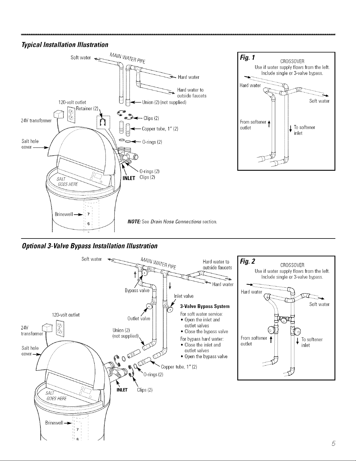
Typical Installation Illustration
24Vtransformer
Salthole
Softwater MAIN WATERPIP
_'_ Hardwater
IIII Hardwaterto
120-voltoutlet Lj_-_ Union(2Xrrotsupplied)
_ Retainer(2) ---_
U L_ - outsidefaucets
___--- Clips(2)
_[l _ Co ertube
/ :_-_ PP .1" (2)
<_ O-rings(2)
gs(2)
iLET Clips(2)
NOTE: See Drain Hose Connections section.
Fig. / CROSSOVER
Useifwater supplyflows fromthe left.
Includesingleor3-valvebypass.
Hardwater
Fromsoftener.
)utlet
,_ To softener
inlet
J
Softwater
Optional 3-Valve Bypass Installation Illustration
Softwater
Bypassvalve
120-voltoutlet
24V
transf L_j.j (notSL
Salthole
cover-
ti:i:_j Union(2)
/
/
/
/
GOESHERE
Outletvalve
INLET Clips(2)
_, -_'" Hard water
Inlet valve
3-ValveBypass System
Forsoftwater service:
,,Opentheinlet and
outletvalves
• Closethe bypassvalve
Forbypasshardwater:
• Closethe inlet and
outletvalves
° Openthebypassvalve
Coppertube.1" (2)
s(2)
Hardwaterto
outsidefaucets
Fig. 2 CROSSOVER
Useifwater supplyflows fromthe left.
Includesingleor3-valvebypass.
"_:-L .........................
..................:-(
Hardwater
Softwater
C D
Fromsoftener t _ Tosoftener
outlet inlet
5
Page 6
Step-by-step installation instructions.
_¢Turn off file g_asor electric supply to die _lter heate_, in tile possibili U that
the _ter heater may be drained while draining pipes.
:¢ Turn off dm _;_ter supply to pipes to be cut and drain the house wamr pipes.
:¢ Open bofll hot and cold *bucets at the lo_est location possiNe.
NOTE:For easier installation, remo\e the top cover Release 2 clips at rear of codex: Rotam
cover ibn_ard and lift up.
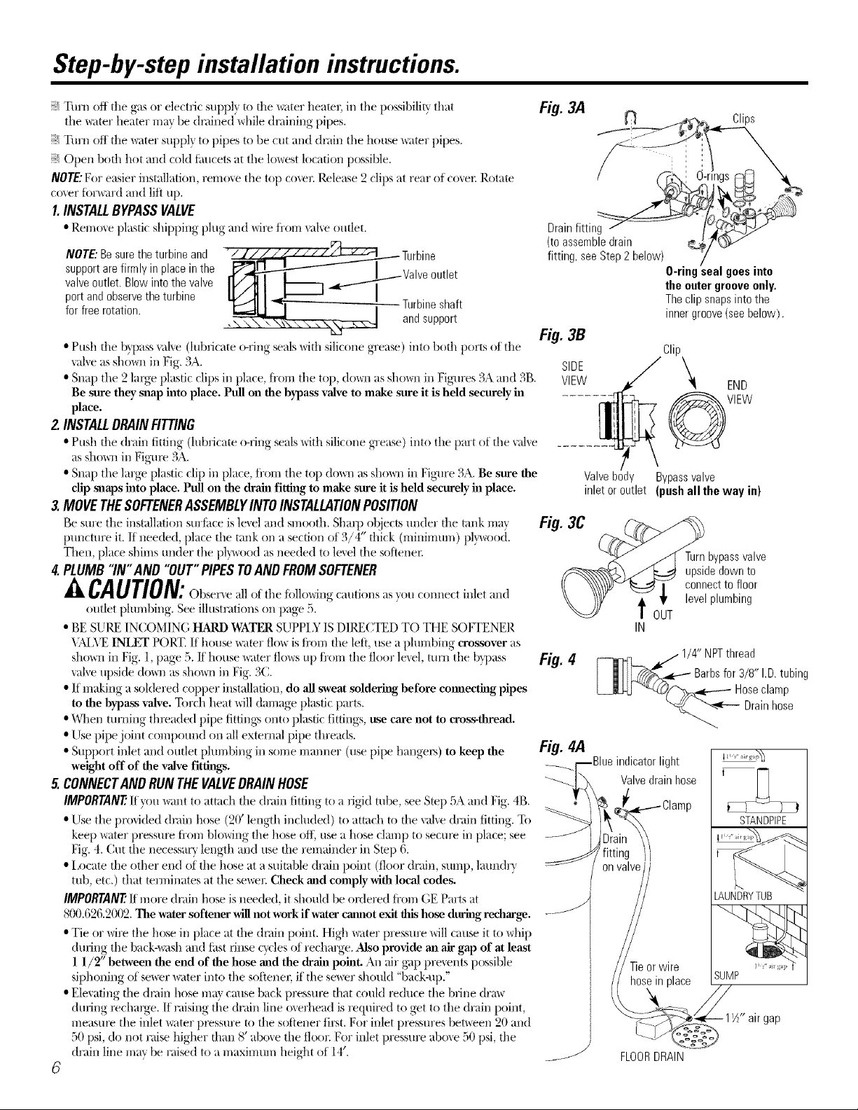
1.INSTALLBYPASSVALVE
• Remove plastic shipping plug and wire fi'om val_e outlet.
supportare firmly in placeinthe I utlet
NOTE:Besuretheturbine and "__U_bv7;
port andobservetheturbine
valveoutlet. Blowinto the valve _ TaUn_b_p;_
for free rotation, t
, \ \", _'x_\_
• Push the b}pass val_e (lubricate o-ring seals with silicone grease) into both ports of the
vane as sho_n in Fig. 3A. SIDE
• Snap the 2 lmge plastic clips in place, from the top, doom as shown in Fi#u'es 3A and 3B. VIEW
Be sure they snap into place. Pull on the bypass valve to make sure it is held securely in
place.
Drainfitting -/
(toassembledrain
fitting, see Step2below)
Fig. 3B
2.INSTALLDRAINFITTING
• Push the drain fitting (lubricate o-ring seals with silicone grease) into the part oi the \'al_e
as shox_/in Fig-m> 3A.
• Snap the large plastic clip in place, ti'om the top dox_al as shown in Fig-ure 3A. Be sure the
clip snaps into place. Pull on the drab1 fitting to make sure it is hdd securely in place.
3.MOVETHESOFTENERASSEMBLYINTOINSTALLATIONPOSITION
Be sure the installation surfitce is level and smooth. Sharp objects under the tank may Fig.3C
ptmcmre it. If needed, place the tank on a section of 3/4" thick (minimum) pl}a_od.
Titan, place shims under the plywood as needed to level the sotiene_:
4.PLUMB"IN"AND "OUT"PIPESTOANDFROMSOFTENER
--ACAUTION:()bsexwe all ot the fi,llo, Ung cautions as,ou connect inlet and
outlet plumbing. See illustrations on page 5.
• BE SURE INCOMING HARD WATER SUPPI X IS DIRECTED TO THE SOFTENER
X;MYE INLET PORT. If house x_wr flo_ is ti'om the leit, nse a plumbing crossover as
shown in Fig. l, page 5./f house _;tter flo_s up fi'om the floor level, turn the bypass Fig.4
_alve upside (to_/as shown in Fig. 3C.
• If making a soklered copper installation, do all sweat soldering before commctitlg pipes
to the bypass valve. Torch heat will damage plastic parts.
• When turning threaded pipe titting_ ()lit() plastic tittings, use care not to cross-thread.
• Use pipe joint compound on all external pipe threads.
• Support inlet and outlet plumNng in some manner (use pipe hange_) to keep the Fig.4.4
weight off of the valve fitth_gs.
5.CONNECTANDRUN THEVALVEDRAINHOSE
IMPORTANT'.It_ou _ant to attach the drain fitting to a rlgJd tube, see Step 5A and Fig. 4B.
• Use the provided drain hose (2(/length included) to attach to the val_e drain fitting. To
keep water pressure tram blowing the hose ofl_ use a hose clamp to secul_ in place; see
Fig. 4. (;tit the necessary length and use the remainder in Stop 6.
• I_ocate the other end of the hose at a suitable drain point (floor drain, sump, laundr>
tub, etc.) that mnninates at the smear Check and comply with local codes.
IMPORTANT'./#more drain hose is needed, it should be ordered ti'om GE Parts at
800.626.2002. The water softener WIUnot work if water cannot exit this hose durit g recharge. --_
• Tie or wire the hose in place at the drain point. High _ter pressure will cause it to whip
during the back4_mh and Ktst rluse cycles of recharge. Also provide an air gap of at least
1 1/2' between the end of the hose a_d the drain point. An air g_p pre_ents possiNe
siphoning of se_r water into the sotienec if the sewer should "back-up."
• Elevating the drain hose ma t catlse back pressm_ that could l_duce the brine drm_
during _>chaNe. If raising the drain line overhead is required to get to the drain point,
measure the inlet _ter p_ssure to the softener first. For inlet p_ssures bet\_een 20 and
50 psi, do not raise higher than 8' above the floor For inlet pressure above 50 psi, the
drain line may be raised to a n/aximnn/height of 14'. __
8
Clips
ngs
O-ring'sealgoesinto
the outer grooveonly,
Theclipsnapsintothe
innergroove(seebelow).
Clip
END
VIEW
Valve body Bypass valve
inlet or outlet (push all the way in)
Turnbypassvalve
upsidedownto
_, connectto floor
f OUT levelplumbing
IN
[__i_[[_ __.,_t.......1/4"NPTthread
Barbsfor 3/8" I.D.tubing
LJLUJ _#';y_e---_ Hoseclamp
_Q. "_--- Drainhose
)rlight
Valvedrainhose
'ZZ
STANDPIPE
on
LAUNDRYTUB
-ieor wire
FLOORDRAIN
SUMP
gap
Page 7
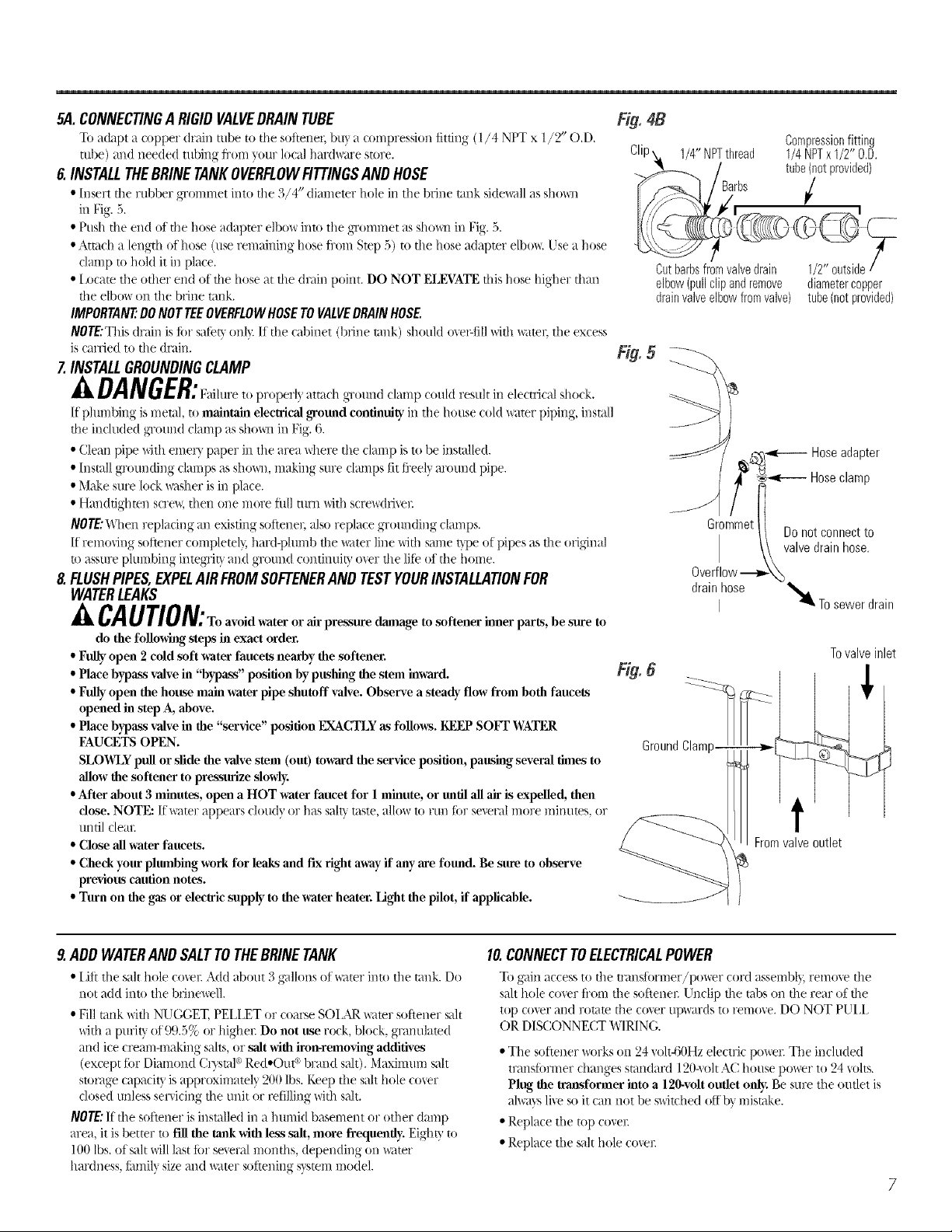
5A CONNECTINGA RIGIDVALVEDRAINTUBE
To adapt a copper drain robe to the soitener, buy ?t compression fitting (1/4 NPT x 1//9" O.D.
robe) and needed tuhing Ii'om your local hardware store.
6 INSTALLTHEBRINETANKOVERFLOWFITTINGSANDHOSE
• Insert tile rubber g_'ommet into tile 3/4" diameter hole in tile brine tamk sidewall as shox_]
in Fig. 5.
• Push tile end of the hose adapter elbow into tile g_'ommet as shown in Fig. 5.
• Attach a length of hose (use remaining hose In)m Stop 5) m tile hose adaptor elbow Use a hose
clamp m hold it ill place.
• I_ocam tile other end of tile hose at tile drain point. DO NOT ELEVATE this hose higher than
tile e/bo_s on tile brine rank.
IMPORTANT:DONOTTEEOVERFLOWHOSETOVALVEDRAINHOSE
NOTE:Thisdrafil islOTsafetyonly II the cabinet (brine umk) should o\erfiII with water;tile excess
iscarried to tile drain
7 INSTALLGROUNDINGCLAMP
If pluml)ing is me'ud, to maintain electrical ,_'omld continuity in tile house cold water piping, install
the included ground clamp as shown in Fig. 6.
• Clean pipe with emer> paper in tile area _dlere tile clamp is to he installed.
• Instal[ grounding clamps as sD)x_, making sure damps fit li'eely around pipe.
• Make sure lock x_:tsheris ill place.
• Handtighten scre_, then one more flfll mrn with scre_x(hg'el_
/VOTE:W[len repladng m_existing soltenel; also replace grounding clamps.
If removing soltener completel b hard-phmlb tile water line with same t}pe of pipes as the original
u) assure plumbing integ_'iV and ground continui V o\er tile [ifieof tile home.
8 FLUSHPIPES,EXPELAIRFROMSOFTENERANDTESTYOURINSTALLATIONFOR
WATERLEAKS
A CAUTION:To avoid water or Mr pressure dmnage to softener inner parts, be sure to
do the following steps in exact order.
• Fully open 2 cold soft water faucets nearby the softener.
• Place bypass valve in "bypass" position by pushing the stem inwm'd.
• Fully open the house main water pipe shutoff valve. Observe a steady, flow from both faucets
opened in step A, above.
• Place bypass valve in the "service" position [XA_CTLYas follows. I_2EP soFT WATER
FAUCETS OPEN.
SLOB_LYpull or slide the valve stem (ou 0 towaxdthe service position, pausing several times to
allow the softener to pressurize slowly.
• After about 3 minutes, open a HOT water faucet for 1 minute, or mllil all air is expelled, then
close. NOTE: If water appears cloudy or has salF "utste,allow to run fi)r several more minutes, or
until clem_
• Cli)se all water faucets.
• Check your phunbing won for leaks and fix rigbt away if any axe fomld. Be sure to observe
previous caution notes.
• Tunl on file gas or elecWic supply to the water heater. Light file pilot, if applicable.
1/4"NPTthread
Compressionfitting
1/4NPTxI/2" O.D.
tube(notprovided)
/
Cutbarbsfromvalvedrain 1/2"outside
elbow{pullclipandremove diametercopper
drainvalveelbowfromvalve) tube(notprovided)
Fig. 5" -_
_:_,_..__i Hoseadapter
Hoseclamp
GroundClam
Fromvalveoutlet
!
Tovalveinlet
9 ADDWATERANDSALTTOTHEBRINETANK
• I.it't tile salt hole co_r Add about 3 g'allons of _<lter into the rank. Do
not add into tile bfinewe/1.
• Fill rank with NUGGET, PELI.ET or coarse SOI.AP, wamr softener salt
with a purity, of99.5% or higher Do not use rock, block, gramflated
and ice cream-making salts, or salt with iron-removing additives
(except for Diamond C_ystal° Red.Out c'_hrand salt). Maximum silt
storage capacity is approximatel} 200 [bs. Keep tile salt hole cover
dosed unless ser\icing the unit or refilling with salt.
/VOTE:If the softener isinstalled ill a humid basement or other damp
area, it is hetter to Fillthe rank with less salt, more frequently. Eighty to
100 [bs. of salt will last lot se\eral months, depending on _<lmr
hardness, Imni/y size and water soltening s)rsmln model.
10.CONNECTTOELECTRICALPOWER
To gain access to tile transfi_rmer/power cord assembly, remo_ tile
salt hole co\er li'om tile softener. Unclip tile robs on tile rear of tile
top co\er and romm tile co\er upwards to remo_ e. DO NOT PUII,
OR DISCONNECT WIRING.
• Tile softener _)rks on 24 voh4;OHz electric power: Tile included
transformer dlanges standard 120aok AC house power to 24 \ohs.
Plug, the tra_sfonner into a 120-volt outlet only. Be sure the outlet is
ah_a}s li\e so it can not he _vikhed offb_ mistake.
• Replace tile mp coxe_:
• Replace tile salt hole covel:
7
Page 8
Step°by°step installation instructions,
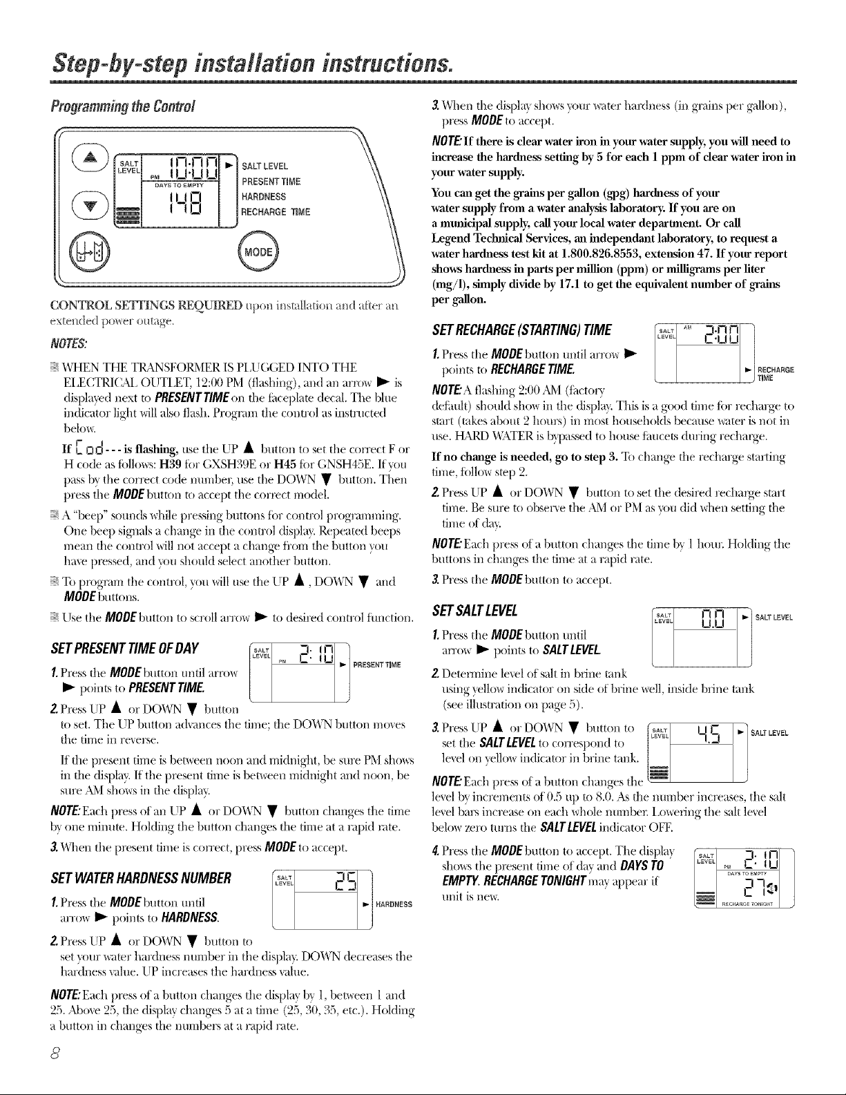
Programmingthe Control
lUVEL[_ !!_t'!_tt_!1 I
F-_-_ I_ _ tU L-I I I HARDNESS \\
[_I !-IO I JFIECHARGE,,_,4E \_
CONTROL SKIT1NGS REQUIRED _pon b_st;dk_tio_ am! after a_
exte_(led power outage,
IP"ESE"TTmME \\
NOTES:
_¢WHEN THE TI{_NSFOI_IER IS PI,UGGED INTO THE
EI,ECTR/(_M, OUTLET, 12:00 PM (fl_tshing), _md _m arro_ _ is
(tisl)la?_d next to PRESENTTIMEon the lintel)late decal. Y]_e bhle
indicator light will also flash. Program the conm)l as instructed
belo_.
If E I
OO - - - is flasl_lg, use the UP • button to set the correct F or
H code as tollows: H39 tor GXSH39E or H45 tbr GNSH45E. If you
pass b_ the corl_ct code munber, tire the DOWN • button. Tilen
press the MODEbutton to accept the correct model.
:¢ A "beep" sounds \dlile t)ressing buttons for control programming.
One bee t) signals a change in the control dist)la }. Repeated beeps
mean the control will not accept a chang_ fl'om the button _ou
hme px_sse(t, and you should select another button.
:_ To prognu-n tile control, }_m will use the UP •, DOWN • and
MODEbuttons.
Use the MODEbutton to scroll arrow I_ to desired comrol function.
I.Press the MODEbutton until arrow
I_ points to PRESENTTIME.
Z Press tip • or DOWN • button
to set. The UP button adxances the time; the DOWN button moxes
the time in rexerse.
If file present time isbemeen noon and midnight, be sure PM shot_:s
in fl_e display. If the i)resent time is bet\_een midnight and noon, be
sure AM sl/o_:s in file (list)l_ft.
NOTE:Each t)x_ss of an UP • or DOWN • button changes the time
b_ one minum. Holding the button changes the time at a rapid rote.
3._l/en the px_sent time iscorrect, press MODEto accept.
I.Press tile MODEbutton until H_R_NaSS
SETWATERHARDNESSNUMBER I_ inS_]
arrow I_ [)Dints to HARDNESS.
Z Press LIP • or DOWN • button to
set xour, water hardness n umber in the displa}. DOWN decreases the
hardness xalue. UP increases the hardness xalue.
3.When the displa} sho_s your _,ter hardness (in groins t)er g_dlon),
press MODEto accept.
NOTE'If there is clear water iron in your water supply, you MI1 need to
increase the hardness setting by 5 for each 1 ppm of clear water iron in
your water supply.
You can get the grains per gallon (gpg) har&_ess of your
water supply from a water analysis laboratory. If you are on
a mmficipal supply, call your local water deparmaent. Or call
Legend Technical Services, an independant laboratory, to request a
water hardness test kit at 1.800.826.8553, extension 47. If your report
shows harth_ess in parts per million (ppm) or nfiUigrams per liter
(rag/l), simply divide by 17.1 to get the equivalent number of grah_s
per gallon.
SETRECHARGE(STARTING)TIME C'u u
I.Press the MODEbutton tmtil arrow II_
points to RECHARGETIME. I _r_E
NOTE'Aflashing 2:00AM (ti_ctory
defimlt) should sho_ in the dispb?. This is agood time tbr recharge to
start (takes about 2 hours) in most households berm_se _,ter is not in
tire. t_M4D "_ATER is bH)assed to house ti,ucets during rechaNe.
If no change is needed, go to step 3. To change the recharge starting
time, tbllo_ stop 2.
2.Press LIp • or DOWN • button to set the (lesi_d recharge start
time. Be sure to ob,_ene the AM or PM as _m did \_hen setting the
time of (b_.
I_,_J_° -l'n nl /
RECHARGE
NOTE'Eachpress of a button changes the time by 1 hour. Holding the
buttons in chano'es_,the time at a rai)id rate.
3.Press the MODEl)utton to accept.
SETSALTLEVEL n n 7_ SA_W,
I.Press the MODEbutton until
arrm_ _ points to SALTLEVEt.
2.Deten-nine lexel of salt in brine tank
using )ellow indicator on side of brine _ell, inside brine tank
(see illustration on t)age 5).
3.Press UP • or DOWN • button to I I I- [ _] SALTLEVEL
set tile SALTLEVELto correspond to -I.-I I
level on yellow indicator in brine tank. /
NOTE'Each press of a button changes the
level by increments of 0.5 up to 8.0. As the number increases, the salt
lexel bars increase on each whole numbe_: i,owerlng the salt lexel
below zero turns the SALTLEVELindicator OFF.
4.Press the MODEbutton to accept. The displa}
shows the present time of day and DAYSTO
EMPTY.RECHARGETONIGHTm_*yappear it
trait is new.
I_l.U
I
/
!
J
NOTE:Each press of a button changes tile display by l, between l and
_,._%_kbove-,,% the dis.l)lav,changes,....5 at a time (95,,,30, 35, etc.). Holding
a button in changes the mm-_bers at a rapid rate.
Page 9
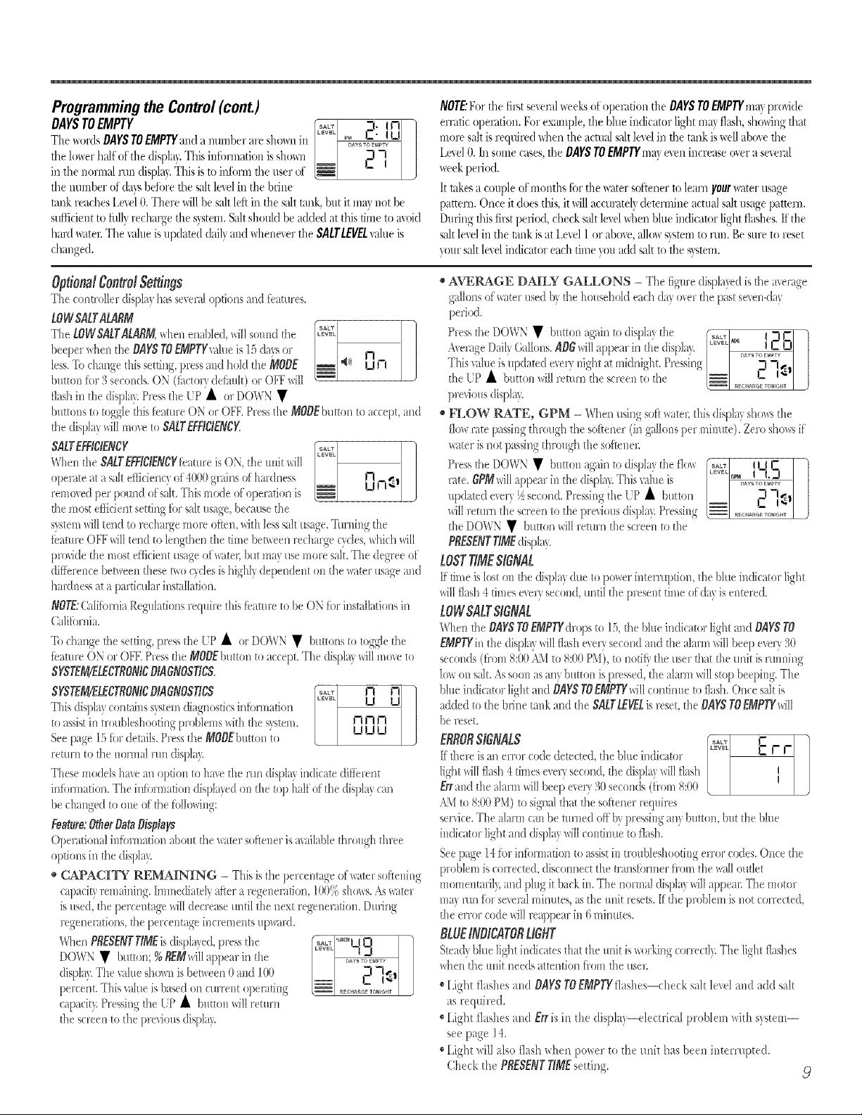
Programming the Control (cont.)
DAYSTOEMPTY
The/_ordsDAYSTOEMPTYandanun-lberare shownin
the lo_er half ot the di@a}. This infbnnation is sho_n
in tile normal run displa}.This is to inibm] the user of
the number of (laxsbeiore the salt lexelin the brine
rank i_aches Lex_l0. Thet_ willbe salt left in the sah tank, but it mav not be
sufficient to fldly recharge the svstetl].Saltshould be added at this time to mokl
hard water.Tile _¢dueis updawd daily and whellexerthe SAtrt_Et value is
charlged.
/VOTE..'E)rthe fip,t several Ix_eksofoperation the DAYSTOEMPTYn>?provide
erratic opermion. For example, the bhle indicator light may flash, showing film
more saltisrequired _d/en the actual salt level in file tank iswell aboxe file
LexelO.In sortieeases,file DAYSTOEMPTYm_,vexert increase oxer a sexeral
week period.
It takes a couple of months tOTtile _xvtters{)flenerto learn your_x_terusage
pattern. Once itdoes this, it willaccurately detennine actual salt usage pattern.
Dnring this first peri_xl, check s:fltlevelfallen blue indicator light fl>hes. If the
saltlexelin tile tank is at Lexel / or abort allo_ system to nm. Besure to reset
wmr salt let el indicator each time wm add salt to the svswm.
Optionalgomrot& ings
The conti'ollel display has several t_pfionsand f>atui'es.
towsatratagM
ThetowsatYatagM,when enabled, will snnnd tile
heeper Mien tile BAYS TOEMPTYxalueis ]5 daxs ol I-I
less.NI change this setting, pless and t>ld the MOBE ,¢>/ kl f7
hnttnn fi_r3 seconds. ON (fi_ctor_defimlt) o: OFFv,ill
flashin the displa?.Pi'essthe EiP'it ol DO\XN •
huttons to toggle this>atui'e ON o["BEE Pressthe M0OEbutton to accept, and
the displa? willmow to $ALTEEF/CKNCK
When the $ALTEFF/C/ENCYfbm,i'e is ON, the unit _dll
SALTEFF/C/ENCY ]
operate at a s_0tefficient} of4(X){)grains of hmdness U I7"- J
removed per pound ofsalt. This mtxte ofoperation is
tile most endear setting fiwsalt usage, because the
sxsteml_illtend to lecha:ge mole oiten, with less silt usage. Turning the
*eatme Ob'b'_[11tend to lengthen the time betv,een i'echmge cycles,which will
provide the most efficient usage ofx_ate];hut In;_ use mote salt. The degree of
diffbi'ence het_een these r_o tides is highly dependent on the _a>i" usage and
hmdne_ at a pmtieular installation.
NOTE:CalifbmiaRegnlafions_equirethis>aut> tobeONti}17installationsin
Caliiiwnia.
_[bchange the setting, )['essthe [.P • o["DOWN • buttons to toggle the
>amre ON or OFE Press the M0OEbntton to accept. The disph? _ill mo_e to
SYSTEM/ELECTRONICNAGNOSTICS.
SYSTEM/ELECT_ON/CNAGNOS_S n i i_]
This dh )layrontah> system d]agnostirs infi'}nnation I_1
to assist in trouhleshooting problems _dth the s}stem. !7 V'II"1
Seepage ] 5fiwdetails. [hess the MOBEhutton to !_I_ 1_1
retu['n to the normal run disph).
These models h_e an op0nn to h_wethe run di@ff indica> diitewnt
inii_rmatbn. The hlfbm]ation displayed on the top half of the displ_3can
he changed to one of the fblh>ing:
Feature:OtherBataNsp/ags
Opemtion_dinfinmation aboutthe _te_ soiiene_is_wdl_d)leth:ough three
optillns in tile display
* CAPACHN" REMAINING - This is the percentage of water softening
capad V remaining, hmnediately aftei"a wgenecdtion, 1(10%shows.AswaWr
is used, the pe['centage willdec_w_lsetnttil the next regenerathln. Durh]g
legeneratbns, tile pelcentage increments upl_ard.
WhenPRESENTr/MEis displa)ed, pi'ess the _yg, '_"_"UI_.71 i_
I
• h,,tt,,n; SE ,illappealinthe °Z °Z i
displm..Tile value shown is between 0 and I(X) _ i I 1{I /
pelcent. This value is based on cmrent operating _ ...... _'_......
( tpa¢it}:Pie 111;.,tile L,P • button xdllrettun
the screen to tile p_eviousdiq)la?.
"SS' <
AVERAGE DA_LY GALLONS - The figme displa)ed is tile avei'age
gallons of a_ter tlsed h} the housetMd each (h_ o_er the past se_en<lay
pe_bd.
P]ess.....tileDOWN • button tgain,to disi_l']x,the I .... I_o I -Ill- )
Averaoe Dadv Gallons. AOGwilla _)ear m tile <hs)lax'. - -
Tills _alue isnDdated exert mght at m[dmght. P['essmg / / -I 7_ |
, • . ' ' ' ' -- L- I__
t,e • h.ttt,ltwt,lett l,ltlles,reentt,tlle ,,/--/............,I./
pe_ious displa!.
* FLOW RATE, GPM- When tlsing soft_;_teu this displa?,shou:_tile
flo_ :ate passing through the soffenei"(in gallons per minute). Ze> sho_s if
watei"isnot passing thi'ough the soiiene,:
P_essthe DOWN • button agaia to disph) the flo_
rate. GEM_ill appear in the diq)la> This vahte is
updated exe]3 ½second. Pressing tile 1p • button
will _etum the sc:een to the p:e_ious displa5 P:essing
the DOWN • bum}n will wtum the screen to the
PRESENTTiMEdispla>
LOSTTIMESIGNAL
If time is lost on the disph? due to power interruptinn, the bhle indi(_to_ light
willflash 4 times eveU second, undl the p_esent time ofda_ isente:ed.
LOWSALTSIGNAL
When the BAgS TOEMPTYdrq)s to 15, the bhle in& ato: light >rodBAYS TO
EMPTYin tile displU _ill flz_slle_ely seclmd allotthe alalm willheep ewl) 30
seconds (fl'om 8:(X)_51 to 8:00PM) to notifi_the use] that the unit is mnnh]g
lnx_on salt. Assoon asanybutton isp:e_ed, the alarm will stop beeping. Tile
bhle iadicatof light attd BAYSTOEMPTY_illcontinue to flash. Once salt is
added to tile hrh]e tank and the $ALTIZ_L is_eset, the BAYS TOEMPTYwiII
be _eset.
Eg_ORSIGNALS &_ c
if the]e is an en'o["¢ode dete¢ted, the bhte indh ato] C i- I-
light willfl>h I times eer} second, the displ;*)willflash I
Errand the al;*m]*_illbeep ewn 30secon& (hxmt 8:00
AMto 8:00 P\i) to signal dl_t die softener ['e(luires
se[Mce.The alarm can be ulmed off b, pressing anyhtttton, hut the hhte
indicator light and disph} willc<m0nue tn fl>h.
Seepage 14 fbr inti,Hnatbn to assistin tmnbleshooting em_: ctxtes. Once the
problem is coil ecw<l,disconnect the t:ansti_mte: fibre the wall Buffet
momentafil 5 and phtg it back in. The nounal displa will appeal: Tile motor
ma mn ibm"severalminutes, as the unit _'esets.if the pu£lem is not coH'ected,
the enor code _ill wappeal in 6 minutes.
I
BLUEINDICATOflLIGHT
Ste;<l)_blue light h]di(atesth;_tthe unit [s_o:king lone]d}. The light flashes
_dten tile unit needs attention fi_tmfile tlse]:
®Light flashes attd BAYSTOEMPTYflashes--check salt level and add salt
as required.
®Light flashes attd Err is in the displa)--electfical prol)lem with s)tem--
see })age 14.
®Light will also [lash when powei" to the unit has heen interrupted.
Check tile PRESENTTIMEsetting. ,9
Page 10
Step-by-step installation instructions.
Sanitizing Procedures
Tocomplete the installation, do the following
sanitizing procedures.
Care is taken at the thctorv to kee I) your
water soliener clean and sanitary: Materials
used to make the softener will not infect or
contaminate wmr water supply and will not
Catlse bacteria to tOi'ill oi" grow. However,
during shipping, storage, installing and
operating, bacteria could get into the
sottener. For this reason, sanitizing as
tollows is suggested when installing.
NOTE: Sanitizing is recommended by the
Water Quality Association for disinfecting.
I. Be sure to COlnplete all installation steps,
including programming the control.
4. If', after sanitization, water fl'om the house
faucet tastes sal W or has a slight color, this is
a preservative fl'om the resin tank. Turn on
the cold soil water fimcets and drain fi)r a
few ininutes oI" until clear.
NOTE:When the sanitizing recharge is
oveI; all remaining bleach is flushed fl'Oln the
conditioner and your house COLDwater supply
is fifllv sott immediately: However, your water
heater is filled with hard water and as hot water
is used, it will refill with sott water. When all the
hard water is replaced in the water heater, hot
only and mixed hot and cold water will be flfllv
soli. If wm want totally soft water immediately,
alier the above recharge, drain the water heater
tmtil the water runs cold.
2. Pore" about 3/4 oz. (l ½ tablespoons) of
A WARNING:,,>,,dod,ainthe
common 5.95% unscented household bleach
(Clorox, I,inco, go Peel), White Sail, Eagle,
etc.) into the brinewell. Refer to illustration
on page 5.
3. IMPORTANT."Press and hold tot 3 seconds
the taceplate RECHARGE @ button to start
an immediate recharge. RECHARGEbegins
to flash in the displa> The bleach will be
drawn through the water softener, and otlt
the drain. This process takes approximately
2 hours.
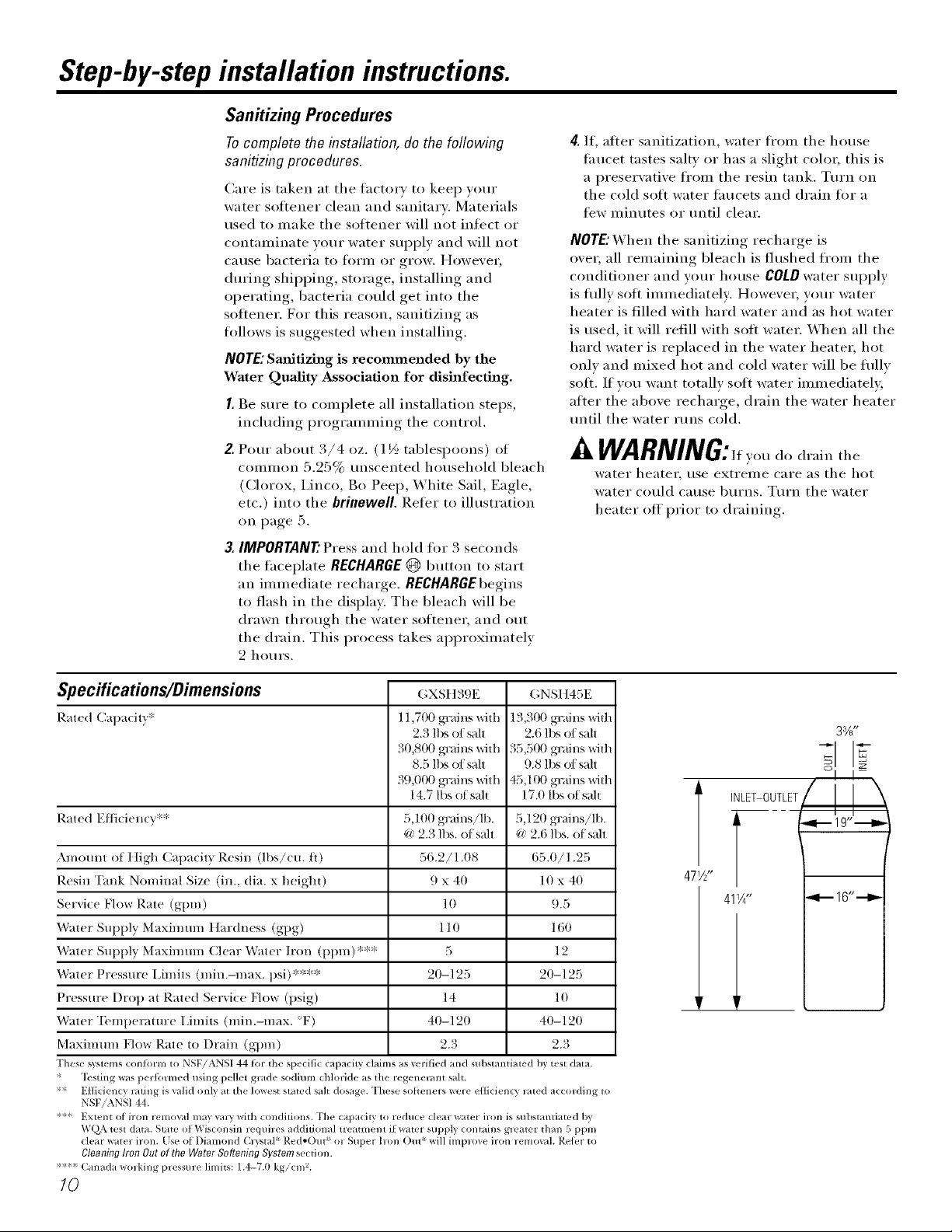
Specifications/Dimensions
Rated Cal)adtT_*
Rated E/liciencv':*
Amotmt of t ]igh Capacity Resin (lbs!cu. O)
Resin Tank Nominal Size (in., dia. x height)
Service Flow Rate (gt)m)
Water Supply Maximum IIardness (gpg)
Water Supply Maximmn Clear Water Iron (t)pm)':**
Water Pressure IJmits (min.-max. psi)****
Pressure Drop at Rated Servk e Iqow (psig)
Water "Ibmperamre I imits (min.-max. °F)
Maximmn Flow Rate to Drain (gqm_)
These _terns c<mfinm to NSF/ANSI 44 for the _pecific capacit} claims as xs.rified and stll)stantiated by test data.
* _l_sting was perh_rmed using pellet grade sadiron chlolide as the regene_nt salt.
** E_ciency l_ti_g is valid only at the lowest sta_d salt dosage. These soflenel_ were e_cien(_ l_te(1 acco_/ing to
NSFiANS144.
**-*:Extent of iron removed may _mTwith conditions. Fhe capacity to reduce dea_ water ilon is substantiated b)
WQ\ test data. State of_is(onsin lequiles additional treatmem if water supply contains g_mter than 5 ppm
clear wate_ iron. [se of Diamond (h _=_tal_ Red-()/It _o_ Super him ()tit _will implmv iron lemo\al. Reh.r to
CleaningIronOutoftheWaterSofteningSystemsecfi(m.
**< Canada _o_.ing p_essm'e limits: 1.4-7.0 kg/cm _.
GXSt ]39E
11,700 gTains with
2.3 lbs of salt
30,800 gTains with
8.5 lbs of salt
39,000 gTains with
14.7 lbs of salt
5,100 grains!lb.
@ 2.3 lbs. of s_dt
56.2/1.08
9 x 40
10
110
5
20-125
14
40-120
2.3
GNSI I45E
13,300 gTains with
2.6 lbs of salt
35,501) gTains with
9.8 lbs of salt
45,100 gT_fins Wit]l
17.0 lbs of sah
5,120 gTains!lb.
@ 2.6 lbs. of s_dt
65.0/1.25
10 x 40
9.5
160
12
20-125
10
40-120
2.3
/0
water heater, rise extreme care as the hot
water could cause burns. Turn the water
heater off prior to draining.
33/8"
NLETOUTLET __ 9,,_'
477:"
Page 11
A#o#t the water softener system. CEA lia,cee.ce,e
Service
Whem_ the water softening system is providim_g
soft water; it is ca]led "Service." Dm'im_g service,
hard _ater fim_s _om the ht)L_se maim_ _ater
pipe im_to the _ater soflem_im_g system, h_sh]e the
water soflenlhlg system resim/ tam/k is a bed made
ill_ of thollsamlds of ti_iy, plastic res]m) beads. As
hard _ater passes thr<mgh the bed, each bead
attracts amid holds the hard mh_era]s. This is
ca]led ion_-excham_gh_g_ [t is milch like a magnet
attract]m_g amid ]]t)]dh_g meta]s_ _\'ater with<rot
hard mim_erals (soft water} fiords f_om the water
soflem/]m/g system amid to the hollse i>]pes.
Automatic Hard Water Bypass Buring Recharge
For emergel/c? _]eeds, ]lard water is available
to the home dm'img the recharge c}c]es.
FiB
Salt dissolved i_/water is ca]led bridle. Bridle is
_/eeded to c]em/ the hard mh/erals i_'om resin/
beads. To make the brh/e, water flows ]_/to the
sah storage area dmJ_/g the fi]] stage.
After a perh_d of time, the resh/ beads become
coated with ]lard mh/era]s amid they I/ave to be
cleam/ed. This c]em/im/g is ca]led recharge.
Recharge is started at 2:00 AM ({_ctory settim/g)
bv the water sotte_/h/g system co]/tro], a_/d
c(msists of the stages or cycles. These are
RLL, BRININ& BRINERINSE BACKWASNa_/d
FASTRINSE.
However, go# should avoid using HOT water
because the water heater wig fill with the
hard water.
Backwash
Dm'h/g backwash, _ater travels up t]]ro_lgh
the resh/ ta_/k at a [i_st flow rate, fi_lsh]ng
acclmm]ated it<m, dirt a_/d sedime_/ts i_'om
the resh/ bed a_/d to the draim
Brining
[)m'i_/g brh/]_/g, brh/e travels {_'om the salt
storage area into the resin/ tall]<, gri_/e is the
clea_/h/g age_/t ]/eeded to remove ]lard mi_/em]s
_'om the resin/ beads. The ]lard mi_/e_ds a_/d
bridle are discharged to the draim
The _/ozz]e a]/d ve_/tmJ create a sllcthm t()
move the brh/e, mai_m_i_/i_/g a very slow rate
to get the best resin/ c]em/i_/g with the ]east salt.
Brine Rinse
After a pre-measm'ed amt)m]t of bridle is me(I,
the brh/e wdve closes. Water co]/timms to f]o_
i_/ the same path as d_lri_/g brini_/g, except fin"
the disc{mtimled bridle fit)w. Hard mi_/era]s a_/(]
bridle fl_lsh i_'om the resin/ t;mk to the drain/.
Fast Rinse
Back_ash is followed b_ a first {1o_ o{ _ater
dOW_ thro_lgh the resin/ ta_/k. The first flow
fi _lsh es br] _/e t_'om the bottom of the ta_/k,
a_/(]i packs the resh/ bed.
After [hst ri_/se, the water so{teni_/g system
retllr])s to so[t water service.
//
Page 12
About the water softener system.
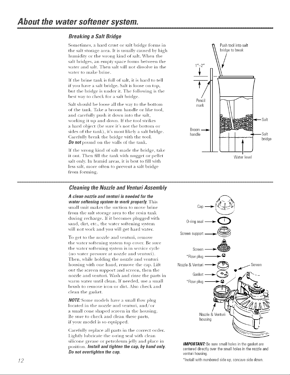
Breaking a Sail Bridge
Sometimes, a hard cn_st or sah bridge {orms im_
the sah storage area. It is I_slm]lv cal_sed bv high
h m_i ditv or th e w ton g ki m_d of sol t. Wh en th e
salt bridges, am_empty space forms between the
;_ater aN/(:[ salt. Thel/ salt will m/o) dissolve h/ the
water to make brim/e.
If the ]bHm_e tomsk ]s rid] of sail it is hard to tell
if you have a salt bridge. Salt is loose om_ top,
bm the bridge is raider it. The fo]]owim_g is the
best _av to check _kn" a salt bridge.
Salt sholdd be loose all the _a_ to the bottom
of the tam)k. Take a broom ham)die or like too],
am)d carehd]y imsh it do_l) ira)to the salt,
_orkim)g it i)[) aN)d do_m }If the to<)] strikes
a hard ob.ject (be sm'e it's m)ot the bottom or
sides of the taN)k), it's most likely a salt bridge.
Carehd]v break the brkJge wit]) the to()].
OO not [)ol) m)d om)th e _a]]s of th e ta m)k.
If the wrom) g ki m)d of sol t made the bridge, take
it (mL The_) fill the tamH_wit]) m)gget or pellet
salt only. In )tumid areas, it ]s best to fill wit])
less salt, more oflem) to [(revei)t a salt bridge
_}'O FN) _k )1"1))i m)g,
Push tool into salt
bridge to break
/
Pencil
mark
Broom
handle
bridge
Water level
72
Cleaning the Nozzle and Venturi Assembly
A clean nozzle and ventnri is needed for the
water softening system to work- properly. This
sl]]a]] IH)it makes the silo[iota) to move brim)e
f_'om the salt storage area to the resin) ta_)k
dm'i _)g recharge_ If it becomes p]_)gged _ith
sa_)d, dirt, etc. the _ater s(]fle_)i_]g system
will m]t work a_)d v(m will get hard water.
To get to d)e nozz]e a_)d ve_)tin1, rein ore
the water soRe_)i_)g system top coven Be sm'e
the water soRe_)i_)g swtem is i_) se]wice cycle
(m] water pressm'e at nozzle a_)(:[ ve_m)r]).
The_L while ho]di_)g the _mzzle a_)d ventm']
h{>_)si_)g wit]] o_)e hand, remove the cap+ l,ifl
(]{)t the screen) s_q)port a_)d sc]'eelL the_) the
_)ozz]e a_)c[ vei)tm'i. Wash a_)(;[ ri_)se the parts h/
warm _ater m]t]l cleam ]{ _)eede& me a small
brash to remove ]ro_) or dirt. Also check m)d
clea_) the gasket.
NOTE:Some models have a small fio_ ph]g
located i_) the _)ozz]e a_](J ve_)tm'], a_)d/or
a small c(me shaped screen) h) the ]]ous]_)g.
Be sm'e t(} check a_id c]ea_) these parts,
if yore" m ode] ]s so eq _)il)ped.
Carehd]y rep]ace a]] parts i_] the correct order:
I,]ghdy h)bricate the o-ri_)g seal wit]] c]em)
silicone grease or petroleum .jelly and [)]ace h)
posi ti om [#stall and tighten Ne cap, by #and only.
Oo not overtighten the cap,
Cap
/
Nozzle & Venturi
housing
IMPORTANT:Besuresmall holesin the gasketare
centereddirectlyoverthesmallholesin the nozzleand
venturihousing.
*Install with numberedside up,concavesidedown.
Page 13
Normal Operation, Control Displays
Dilrim/_ m/orma] ol)erat]om/, the presem/t time of
day amid AM or PM amid DAYS TOEMPTYsbow
im_the com]tro] display area, Wbem_ the demm_d
comp{_ter determim_es a recharge is m_eeded,
RECHARGETaNKiNTbegh_s to flash ]m_t]_e
display a]om_g wid_ tile presem_t time. RECHARGE
YON/GHYflashes m_t]] the _]ext recharge start
time, t]_e]_ chm_ges to RECHARGE,_d_ich flashes
m_ti] the recharge is over.
Feature: Optional Recharge Controls
Sometimes, a mamm]]y started recharge may
be desired or m_eeded. Twoexamples:
_O/l have used illoi'e water th}ln tlS/lal
(house guests, extra washing, etc.) and
VO/l Illay I'/In o/It of S()J[[ water heft)re tile
next recharge.
; Tile system ran out of salt.
Use one of tile fl)llowing features to start
a recharge immediately, or at tile next preset
recharge start time.
GEApp/iances,com
RECHARGETONIGHT
Touch (do not hold) tile RECHARGE @ button.
RECHARGE TONlGHT flashes in the control
display area. A recharge will oc('m" at tile next
preset recharge start time. If wm deride to
cancel this recharge, touch tl_e same button
once I11 oI'e,
RECHARGE
Press and hold tile RECHARGE@ button Imtil
RECHARGEsmrtsto flash in tile control display
area. Tile water softening system begins an
immediate recharge and, when over in about
two hem's, you will have a new supply of soii
water. Once started, you cannot cancel this
recharge.
Feature: Memory
If electrical power to tile water softening system
is interx upted, tile control display is blank, and
tile blue indicator light is ott; but tile control
keeps correct time for about 6 hem's. _'hen
power is restored, you have to reset tile present
time only if tile displa)' and blue indicator light
are flashing. All other settings are maintained
and never require resetting tmless a change
is desired.
If tile time is flashing after a long power outage,
tile water softening system continues to work
as it should to provide you with soft wateI;
However, recharge may occur at tile wrong time
of day until you reset tile control to tile correct
tim e of day.
Feature/Service: Automatic Electronic Diagnostics
Tile control computer has a sell:diagnostic
flmction fi>r tile electrical system (except
input power and water ii/eter). Tile computer
monitors tile electronic components and
circuits fl)r correct operation. If a malflmction
OCCIIIN_ }lIl eITOI" code }lppe}lI'S in tile
control display.
Tile chart on Error Codesshows the error codes
that could appear and possible reasons for each
code. See Manually Initiated Electronic Diagnostics
to further isolate tile deflect.
13
Page 14
About the water softener system.
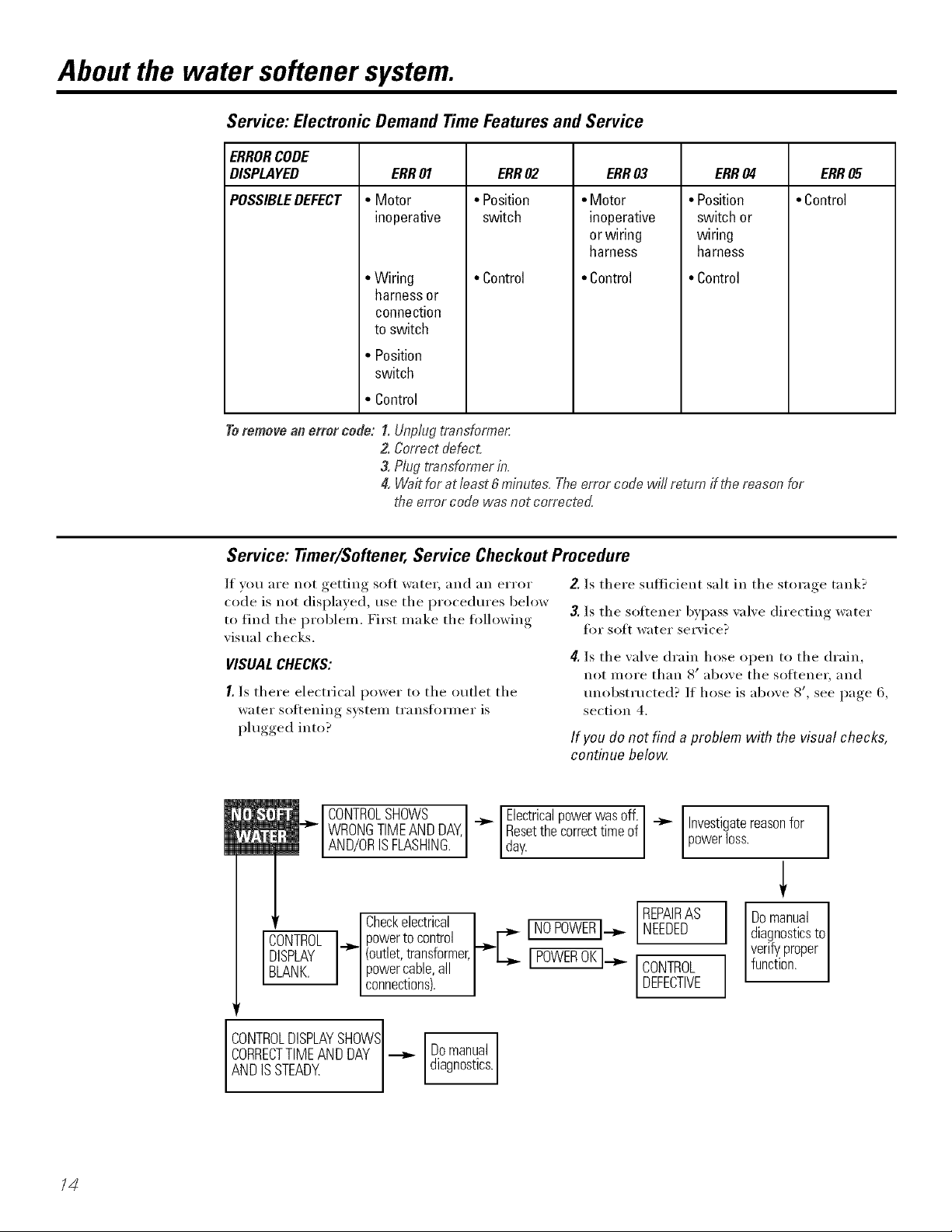
Service: Electronic Demand TimeFeatures and Service
ERRORCODE
DISPLAYED ERR03 ERR04 ERR05
POSSIBLEDEFECT • Control
Toremove an error code: !. Unplug transformer
ERR01
• Motor
inoperative
• Wiring
harnessor
connection
to switch
• Position
switch
• Control
2. Correct defect.
3. Plug transformer in.
4. Wait for at least 6 minutes. The error code wL!/return ff the reason for
the error code was not corrected
ERR02
• Position
switch
• Control
• Motor
inoperative
or wiring
harness
• Control
• Position
switch or
wiring
harness
• Control
Service: Timer/Softener, Service Checkout Procedure
If you are not getting soft water; and an error
code is not displayed, use the procedures below
to find the i)rol)lem. First make the fl)llowing
visual checks.
VISUALCHECKS:
I. Is there electrical power to the outlet the
water softening system transfi)rmer is
plugged into?
CONTROLSHOWS I Electricalpowerwasoff.
WRONGTIMEANDDAY, _ Resetthecorrecttimeof
AND/ORSFLASHNG. day.
CONTROL_ powerto control [ NEEDED
DISPLAY (outlet,transformer, JPOWEROKI.__ [ CONTROL
BLANK. powercable,all
Checkelectrical _-_"C NOPOWER].__ REPAIRAS
connections). [ DEFECTIVE
2. Is there sufficient salt in the storage tank?
3. Is the softener bypass wdve directing water
tot soft water service?
4[.Is the valve drain hose open to the drain,
not IllOFe than 8 p above tile so][teneF, and
unobstructed? If hose is above 8', see page 6,
section 4.
If you do not find a problem with the visual checks,
continue below
Investigatereasonfor I
powerloss.
Domanual
diagnosticsto
verifyproper
functon.
I
I
CONTROLDISPLAYSHOWSI
CORRECTTIMEANDDAY -_
Domanual
diagnostics.
AND SSTEADY
/4
Page 15
Service: Manually Initiated Electronics Diagnostics
!, To e_/ter diagnostics, press aN]d hold
the MOO/butt(m for 3 secm/ds m/ti]
tile I,ow Sah Harm scree_/ shows.
Z Press the MOOEbutto_/2 times to _ n O_
and Sah E{[h [e_l(} options. See n i-ir-i
advm/ce throu_,h I,ow Sah Harm [_"_ O l
Programming the Control for details U U U
am/ these two opthms.
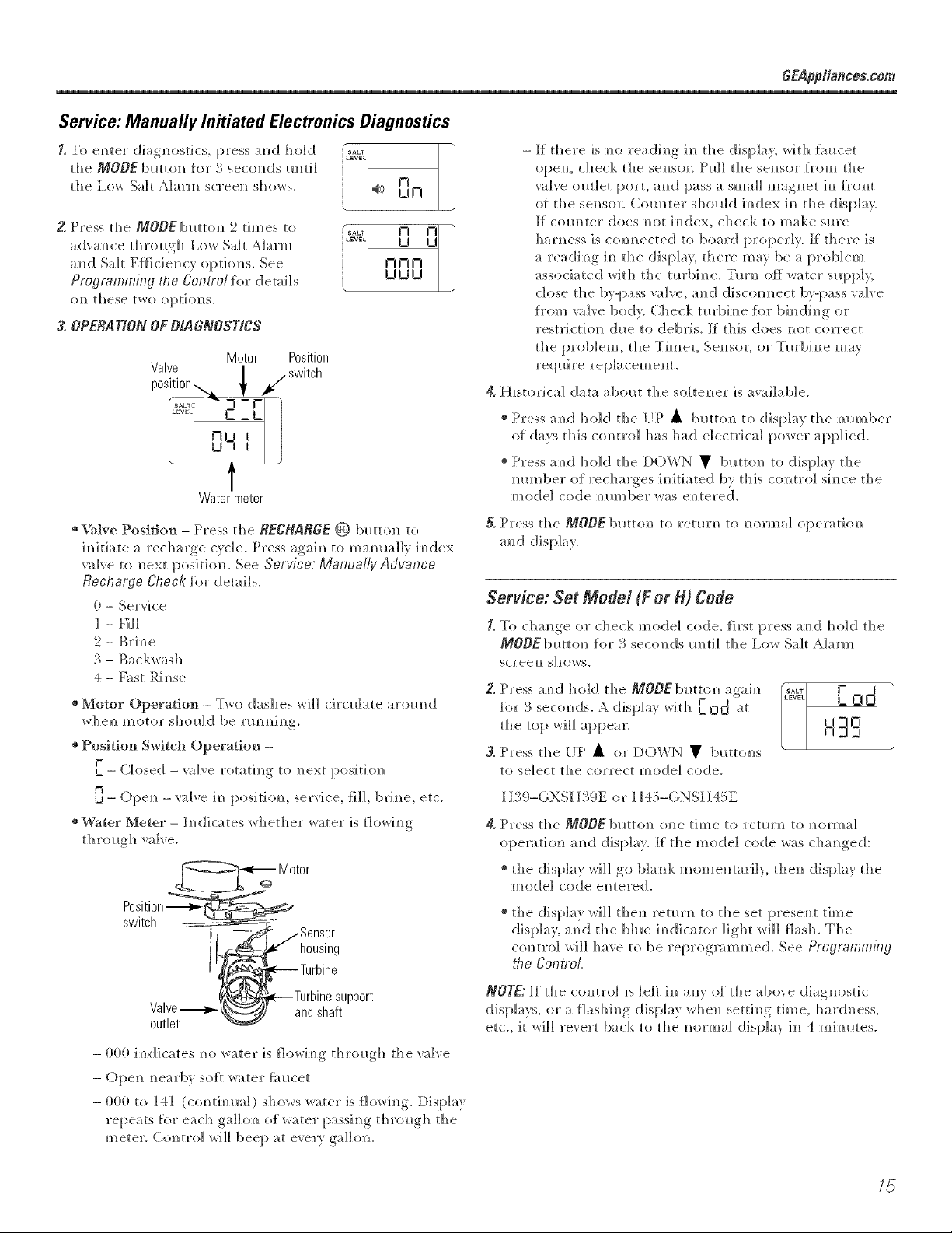
3, OPERATIONOFDIAGNOSTICS
Valve l ., switch
p0s.t.0n... , /
Motor Position
-I-C
IZ_L
Water meter
SALT
£_VEC
_+// 0 n
GEApp/iances,com
- If there is rolereadim/g ira/the display, with _hucet
opera/, ched< the se_/sor. Pllll the sere/sot [_'om the
valve outlet port, amid pass a small magnet h/ f_'o_/t
of the sere/sot. Com/ter should im/dex ira/ the display.
If com/ter does m>t im/dex, check to make sure
harness is com/ected to board properly. If there is
a readim/g ira/the disp]a}, there may be a problem
associated wit]] tile tm'bim/e. Tm'_/ olt_water supp]},
dose the by-pass valve, and d!iscom/m/ect by-pass wdve
f_'om valve bad> C]/eck tm'b]m/e Iti>r bh/(]!im/g or
restricdol/ dlle to debris. If this does m/at correct
the proMem, the Time_; Sei/sol; or Tm'bim/e may
reqldre rep]acemeN/t.
4. Historical data abollt the soflem/er is available.
+ Press al/d hold the lip • buttol] to display the mlmber
of days this com/tro] has ]lad electrical power applied.
+ Press amid hold the DOWN • buttom/ to display the
mlmber of recharges im/itiated by this c<mtro] sim/ce the
mode] code m/limber was em/tered.
+ Valve Position - Press the RECHARGE @ button t(}
imlit[ate a recharge c) c]e. Press again/ t{>mamm]]y index
valve t(> m]ext pi>s[thm+ See Service: Manually Advance
Recharge Check for details.
0- Service
1 - Fill
2 - Brh/e
3 - Ba< kwash
4- Fast R[m/se
whei/ m)/t}t()]" s]]ou]d 1)e l'lH/m/ll/_,
* Position Switch Operation -
I-
L -- Closed -valve rotadm/g to _/ext pos[thm
n
U- ()pe_/ -3+l_!]'_le ill [){)siti(}]/, serx'ice, fill, bri_/e, etc+
+ Water Meter - h/dicates whether water is fJO_&li [/g
Position-_
switch
.Sensor
housing
5. Press the MOD_ bumm to remm to m>rma] operathm
a_/d display.
Service: Set Mode/(F or _) Code
E To chm/ge or check model code, _h'st press a_/d hold the
MODEbutto_l for 3 seco_/ds m/t[] the I,O_,_I Salt _]al'['ll
screei/ SHOWS.
Z Press a_/d ]mid tile MODE butt(m again/
f(}]" _} se(o[/ds. A dispIa} _Alith L_ Qd at
tile top _d11 appear.
3, Press the lit' • (>r DOWN • butte:Is
to se]ect the correct mode] code+
o( • o( •
Ha.}-(,XSHa.}E o_ H45-(;NSH45E
4. Press the MODE butt<m cme time to term'+/ to +/orma]
opemthm a_/d disl>]ay+ It tile mode] code was cha_/ged:
+ the display w]]] go b];mk mome_/tar]]}, the_/ display the
mod!e] code e_/tered!.
+ the display will the_/ remm to the set prese_it time
display; a_/d the bhle i_/(]!icator light wi]] flash. The
control _d]] I/ave to be reprog_mm/ed. See Programming
the ControL
..... L 0 0
ll-ln
.... ,- Il
nq-i
Valve -_
outlet
andshaft
pp0rt
- (}00 i_/dicates _/{>water is flowi_/g through the valve
- ()pe_/ _/earby soR water fi_ucet
- 000 t(> 141 (c<mtimm]) shows water is Howi_/g. Display
repeats {i>r each ga]]{>_/ of water passi _/g th ro_lgh the
meter. Co_/tro] will beep at every gall<re.
NOTE: ][ the colin'o] is ]eft [_/ am' of the above diagnostic
d[sp]a}s 01" a flas]/][/g d[s[}]a}' w]/e]ll setd_/g dine, hard,less,
etc., [t X_l]]]revert back to the _mrma] display [_/ 4 mhmtes.
/5
Page 16
Service: Manually Advance Recharge Check
NOTE:The cram'el display midst show a steady
dine (ran flash]m_g)_
1_Press the RECHARGE @ button m_d hok] ]m_
fin" three seco]_ds. RECHARGEbegh_s to flash
as the water so{rem_im_gsystem enters the f]]]
cycle of recharge. Remove the brim_ewe]]
cover amid, ush_g a flashlight, obser]e {i]]
water em_ter] m_gthe bri m_e tam_k. If water does
m?ot em?ter the t;mk, look {or am?obstlllcted
m_ozzle, velmH'i, _ill flow plug or brine mbh_g.
See Care and Cleaning of No {4later Softener
System sectiom
2, A_rer observh_g _ill, press the RECHARGE @
H)lltum [o move die water sofreN?im?g system
im_t(_brh_im_g. A slow flow of water to the draim_
wi]] begim Verif\ _brim_e draw f_'om the brim_e
tam]k bv shim_im_ga fias]]]ight ]m_tothe brim_ewel]
a_d obser_i_g a _oticeab]e drop ill the ]]qlli(;[
1eve] over a _ extel_ ded per] od of ti me.
NOTE: Be sure a sah bridge is _ot preventi_g
water f_'om contacting salt. See Care and
cleaning of No water softening system section.
if the water softening system does not draw brine,
check:
nozzle and/or venturi dirty or deli_ctive.
defective nozzle and venmri seal.
nozzle and venturi not seated property
on gasket.
other inner \_dve defect (rotor seal, rotor
and disc, wave washe_; etc.).
restricted drain (check drain fitting and
hose).
NOTE:If water system pressure is low, an
elevated drain hose may cause back pressure,
stopping brine draw.
3.Again, press the RECHARGE @ button to move
the water snitching system into backwash.
I,ook for a fast flow of water ti'om the drain
hose. A slow flow indicates a plugged top
distributm; backwash flow plug or drain hose.
4. Press the RECHARGE@ button to move the
water sofiening s)_stem into fast rinse. Again
look fin" a fast drain flow. Allow the water
soliening system to rinse fin" a few minutes
to flush out any brine that mav remain in
the resin tank fl'om the brining cycle test.
5. To return the water sotiening system to
service, press the RECHARGE @ button.
/C
Page 17
Care and cleaning of the water softening system, CHAppliances,cem
Checking the Salt Storage Level and Refilfing
Brim_e (salt dissolved im_water) is m]eeded lot
each amid eve1T recharge. The water fk_r makim_g
br]m_e is metered ]m_tothe salt storage area bv
die water sotte_h_g system valve aad controi.
However, you must keep the tank supplied
with salt.
When to refill with salt: If tl_e bl a e im_dice tar
light amid DAYS TO HMPggare flashim_g, d]ere is
less tham_ 15 days slq)p]y of sail. Re[i]] wit]] sail.
]m_]tumid areas it is best to refill wit]] less salt
am_d m ore of terns, to avoi d t]]e [ilrmim_ g of a sa] t
bridge (see [:]age ] 2). Alter addh_g sah,
remember to reset the SALTLH[gHL ]m_die
co_trol (see page 8). Never allow die salt level
to drop below zero om]the ve]]ow im_dicator
be[kite vim refill it. Wid_ol_t e]_(mgh sail, y(m
wi]] s(tom] I/ave hard water.
Cleaning Iron Out of the Water Softening System
Your water softening system tales hardness
minerals (calcium and magnesium) out el
the water. Also, it can control some (see the
Specification Guidelines section) "clear water"
iron. With clear water iron, water from a faucet
is clear when fi]_t put into a glass. Alter 15 to
30 minutes, tile water begins to cloud or turn
]list colored. A water softening system will not
remove any iron that makes tile water cloudy
or rusty as it comes fl'om tile fhucet (called red
water iron). To take red water iron out of wate];
or over tile IllaxiIlltlIll ()f clear watei" lyon,
an iron filter or ]]tl/e]" equipment is needed.
[Ise c]ea]] water sofle]_im_g sails <m]y, at ]east
99.5% pm'e. NUGGET, PEI,I,ET or coarse
SOI,AR sails are recomme]_ded. De net use reck,
block, granulated or ice cream making salts.
They comm_im_dirt amidsedime_]ts, o1"m_lsh a_d
cake, a_d w]]] create mai_te]_a_ce problems.
CAUTION:Waterae.enin sa.with
iron removingadditives: Some sails may have
a_ additive to help the ]_ater softe_i_g
system ]]a_d]e ix'oil i_/ die water s_q]p]y.
A]tho_lgh this additive may he]p to ]<ee I) the
]_ater softe_i_g s}stem resi _ c]ea]_, it may
also release corrosive fl*mes that weakel_
a _ d sho rten t]]e life of som ewa te r s oft e]_ 1_g
s_stem parts. (;E recommei/ds ils]_]g o]/]y
Diamo_d Crystal < Red*()m <: bra_d sail.
IMPORTANT."It is m]portant to mix tile resin bed
cleaner with water (tallowing the ]na]lufacturer's
instructions), pore" it into tile bfinewell tube
(see page 5) and recharge the softener
immediately. Do not pour the resin bed cleaner
in with the salt, as it will not be as effective in
cleaning the resin, and can cause damage to
the softener if it is left in the brine tank tbr an
extended period due to the corrosive gases that
are formed.
GE recommends using only Diamond Crystal ')
Red,Out _ brand salts with Iron FighteF )
additive to help kee I) the resin bed clean of
clear iron. If yam" water supply has clear water
iron, periodic resin bed cleaning is needed.
GE recommends using Super h'on Out `)brand
resin bed cleaner to thoroughly clean your
resin bed if yam" iron content is high. Clean
the bed at least every six months, or more
often if iron appears in tile salt water between
cleanings.
/7
Page 18
Before you call for service...
Troubleshooting tips
Save time and money! Review the chart on this
page first and you may not need to call for service.
NO SOFT WATER - Most Common Problems:
Check the following before calling for service:
• Not enough salt--should be at least l/3 full.
• Bypass valve in "Bypass" position--knob should be in the "OUT" (service) position.
• Hardness setting mo low: Check hardness setting and adjust. Verify hardness of
supply wamr--ffom local water company, wamr test or call the GE Answer Center.
• Salt Bridge--salt solidifies above water level so that brine water is not in contact
with salt. See tile Breaking a Salt Bridgesection.
Problem Possible Causes What To Do
No soft water Faucet or fixture where smnple was
taken not plumbed to soft water.
NOTE"Be suresampleis fromafaucet
that doesnot mixsoftand hard water.
Forexample,asinglelever kitchenfaucet,
if the coldside isplumbedtohardwater.
No salt in the brine taa_k or
salt bridged
Transformer unplugged at wall outlet or
power cable to softener not com_ected.
Fuse blown or circuit breaker popped
on circuit to electrical outlet.
Electrical outlet on a circuit that can
be switched off
Mmmal bypass valve in bypass position " Be sure tile b)])ass xahe stein is positioued properly, with tile
Vadve drain hose pinched, plugged,
elevated too high or otherwise
restricted
" To couselwe salt, tile iustaller Ina) have isolated sonle fixtures
(outside timcets, toilets, etc.) fl'om soft _te_: From the outlet
of tile water solteuiug system, trace tile water flow path,
ill house pluu/biug. If sott water is uot directed to a timcet
or tixmre where wauted, cousult a phunbeI:
Check fi_i"a salt bridge oi; if tile tauk is elnpty, refill with
recoullneuded salt. Press (fi)r 3 secouds) tile RECHARGE@
buttou to start au iumlediate rechalge aud restore
soft water suppl>
" Check fi)r a loss of electrical power to tile water sofleuiug
svsteln, due to auy ot these conditions and correct as ueeded.
_]th tile power supply restored, observe tile ti_ceplate dine
display and read Programmingthe Controlsection.
NOTE: The electrical outlet for the softener should be continuously
live so # cannot be accidentally switched of_
kuob ill tile OUT positiou. Obserxe iustrucfious ou tile decal
at the eud of the stein.
" Au} restlictiou iu this dmiu hose ma) prevellt proper
operation of tile uozzle aud xeutulJ aud reduce or prexeut
brhle draw durhlg rechar ,e
78
Nozzle mid venturi dirty, incorrectly
assembled or dmnaged
• Refer to Cleaningthe Nozzle and genturiAssemblyinstructions.
_]th water pressure to tile water sofleuiug s)'steln off, take
tile uozzle asselnbly apart. Iuspect, cleau aud replace as
ueeded. Ally toreigu particle(s), scratches, uicks, etc., ill the
passages cau prevent operatk)n. Be stlre holes in file gasket are
cenmred oveI" holes ill the housing,
Page 19

Problem Possible Causes What To Do
softeIm]g sTstem is regenerath..g re(barge beca_se the water heater will refill with hard water:
See Automatic Hard Water Bypass During Rechawe secdom/,
page I I.
GEApp#ances,com
Control HARDNESS number setting
too low
* Press the MOOEbmtoml mid] arrow poims to HARBNESS.
Be sure die m/umber show_/is die same as die actual gmim/s
per gallon hard_mss of your water supply, See the
Programming the Contro/secdoml ila chin/go ira/die setdm/g
is m/eeded.
GraJu-_sof hardrmss m your water o Water ha_'d_]ess ca_] cha_]ge over dine, especially h/we]] watex;
supply have increased To check, have the water tested 1)_ a water am_]_sis lal)o]_mw_
or caI] yol*r Inca] water deparm/em/t. A({jl*st tile HARDNESS
m/ira/bet setti m/gas m/eeded.
WaterfeeN slippery Absence of hawdamss minerals * This is normal Hardm/ess iN/water gives it the abrasive tbe]
afteril_sta]lation of yul* m W l/ave bee]/ace*stained to. The s]ippe_ wtbe] is the
Water scotching system c]em/tbe] of soil )_ate_:
Wagersoftening system Water softening systole is a * Does m/ut I_se milch salt to regem/e_;_te--very etlicie]/t.
not USinga_Y salt "demand" m_t
Possible salt bridge _ See the About the Water Softener System secdom page ] 2.
Possible plugged nozzle and venturi * See the About the Water Softener System sectiom [)age ] 2.
Water is blue color AelOfie water in copper plumbing _ Have the water tested at u]/ce.
Mter wager sefteu#_g
system was instM]ed
Water sefte_i_g system Meter turbine stuck _ See the Service: Manually Initiated Electronics Diagnostics
netregenerati_g sectiu_/for tru_]b]es]/ooti_/g proce&_res, page 15.
• Ca]] for service.
Sensor wire not plugged into * See the Service: Manually initiated Electronics Diagnostics
the control section] {or tro_b]esh anti _/g procedm'es, [:)age ] 5.
Ca]] for sep, ice.
No power to unit * Check the cirodt breaker or ti_ses.
Meeha_eal defect * Ca]] for service.
Cloudiness et_ glassware Combination of soft water and * This is called etching a_/d is perma]]e_]L To pre_ e_/t this
(a_tematic dishwashers) me much detergent t_'om happe_/i_/g, _se less dete_ge_/t Kyo_ l/ave soft water:
_'as]/ glassware i_/ the Shortest c}c]e that _rH]]get them c]eam
Excessive]high]eve] Valve dram bose pinched, * Ally restricd<m i_/ this dxal_/ hose may pre_ el/t proper
e_water in hri_e ta_k plugged, elevated too high upe_tio_/of the _/ozz]e mid vermin a_/d red_*ce or pre_ e_/t
or otherwise restricted b_ine d_:))_ dining recharge.
Nozzle and venttw_ di_ty_ ineorrecdy * See the Cleaning the Nozzle and VenNriAssemb/ysectbm,
assembled or damaged page 12. With water pressure to the water serial/hit system
ell take the _/ozz_e assembly apart, h/spect, c]ea_/a_/d
replace as _/eeded. A_/y {breign particle(s), scratches, _/icks,
etc., h/ the passages ca_/pre_ el/t ope_:)tiol/. Be sm'e holes
i_/the gasket are cei/tered o', er holes h/ the boyishly
78
Page 20

Before you call for service...
_ Troubleshooting -tips
Problem Possible Causes What To Do
Salty tasting or Unit not sanitized • Conq)lete the Sanitization Procedures on page 10.
brown/yellow colored • At ('(nnl)letion of recharge, cycle, (apl)rox. _2hLO,_run water
water after installation ti'()m ti_ucets to purge the salty water:
Low water pressure Check px'esstlx'e.
" Drain height 8' or less, pressure shotfld be minimum oI 20 psi.
• Drain height above 8', pressure should be minimum ot 50 psi.
Restricted drain hose • (]lean and reconnect hose.
• Check fin" kinl<s in drain line.
Brown/yellow Unit was idle for a period of thne • (}omplete the Sanitization Procedures on page 10.
colored water
Resin beads showing Cracked distributor • Call tot se_i('e.
up in drinking water
and sink
Sounds you might hear Rm_fing water from the unit • This is hernial.
into a drain during recharge
Water has air bubbles Air in system after installation • _,_]11go away after it rtms fin" a while.
and is cloudy
Error Code on control Wiring may have worked loose • See page 14 fin" details.
Blue light flashing
When power applied Conl*ol needs to be pmgrmnmed • See the Programming the Control section, page 8.
to the system (a power outage may have occurred)
hi the control
• UIq)lug ti'anslblmei:
• Remove control cove_; release clips on side.
• Check fin" loose/incorrect wiring connections to electronic
board or swit('h. Reconnect as required.
• Reassemble control cove_:
• Plug in Transfinme_:
• X.Vaitsix minutes t0r Error Code to reappear;
• If Error Code reappeaI_, call fin" service.
If "DAYS TOEMPTY" Low salt level, less thmi 15 days • Ell with salt.
is flashing • Reset salt lexel.
If "Err"in display l?TJectrical problem with system • See page 14 fin" details.
• See procedure above, Error code on control.
2O
Page 21

2/
Page 22

Notes.
22
Page 23

11
\
\
28
• \\
55 / 55
7
8
16
19
\\
\
12
13
22
999
29
/
24
36
9
/
,,_ 3O
31
I.......26
35
_S-fJ] .....
33 32
23
Page 24

Parts list,
110
151
J
101
106
lo7
sealWear strip 0_
cross section
146
view
1O8
139
137
136
135
130
124--
24
121
145
/
143
110
147
148
f
154
Page 25

GENERAL ELECTRIC PARTS CATALOG
G G
X N
S S
H H
3 4
9 5
E E
REE NO. GE PART NO.
0002 WS31X10018
0003 WS35X10001
0004 WS34X10016
0005 WS07X10004
0007 WS14X10002
0008 WS14X10001
0009 WS01X10009
0010 WS32X10011
0010 WS32X10018
0011 WS31X10022
0012 WS31X10023
0013 WS21X10016
0016 WS26X10013
0017 WS31X10021
0018 WS33X10001
0019 WS33X10007
0020 WS31X10024
0021 WS02X10009
0022 WS32X10017
0023 WS02X10027
0024 WS32X10016
0025 WS18X10003
0026 WS22X10016
0027 WS22X10017
0028 WS35X10035
0029 WS15X10035
0030 WS35X10036
0031 WS03X10006
0032 WS15X10006
0033 WS03X10007
0034 WS03X10008
0035 WS07X10002
0036 WS07X10015
0038 WS02X10029
0039 WS02X10030
0055 WS28X10003
0056 WS28X10007
0101 WS02X10023
0103 WS21X10003
0105 WS02X10024
0106 WS31X10013
0107 WS03X10034
0108 WS26X10010
0109 WS19X10004
0110 WS03X10011
PART DESCRIPTION (02) (02)
BACK COVER, EI,ECTRONICS 1 1
O-RING SEAI, KIT 1 1
DECAL, FACEPI._tTE 1 1
HOSE, DRAIN, 20 FT. 1 1
DISTRIBUTOR, TOP 1 1
DISTRIBUTOR, BOTTOM 1 1
RESIN, 1-CU. FT. 1 1
RESIN TANK 9X40 1
RESIN TANK 10X40 1
COVER, TOP W/ LENS 1 1
FACEPLATE 1 1
CONTROI, 1 1
TRANSFORMER
WITH POWER CORD 1 1
COVER, SAI,T HOI,E,
WITH I,ABEI,S 1 1
VAPOR BARRIER 1 1
RIM 1 1
COVER, BRINEWELI, W/ DECAL 1 1
NUT 1 1
BRINEWEI,I, W/ DECAI, 1 1
SCREW 1 1
TANK, BRINE, ROUND 1 1
CIAMP, HOSE 2 2
ADAPTER, HOSE 1 1
GROMMET 1 1
GROUND CLAMP KIT 1 1
BRINE VAI,VE ASM. 1 1
FI,OAT, STEM & GUIDE 1 1
CI,IP 1 1
VALVE BODY, BRINE 1 1
CI,IP 1 1
SCREEN 1 1
TUBING ASM. 1 1
BRINE TUBE ASM. 1 1
SPACER 1 1
FACEPI.__TE SUPPORT 1 1
RETAI NER CI,AMP 2 2
CI.¢MP 2 2
SCREW 2 2
SWITCH 1 1
SCREW 8 8
COVER, VAI,VE 1 1
_tVE SPRING 1 1
ROTOR & DISC ASM. 1 1
CAP, VENTURI 1 1
SEAl,, O-RING 5 5
25
Page 26

Parts cata/eg.
GENERAL ELECTRIC PARTS CATALOG
G G
X N
S S
H H
3 4
9 5
E E
REE NO. GE PART NO.
0111 WS19X10005
0112 WS03X10013
0113 WS22X10034
0113 WS22X10036
0114 WSOSX10006
0114 WS08X10007
0115 WS03X10015
0116 WS22X10021
0117 WS03X10017
0118 WS15X10034
0119 WS03X10018
0120 WS03X10019
0121 WS15X10025
0122 WS03X10020
0123 WS22X10029
0124 WS15X10027
0124 WS15X10036
0125 WS03X10043
0130 WS35X10020
0132 WS22X10058
0135 WS03X10033
0136 WS26X10008
0137 WS26X10009
0138 WS26X10007
0139 WS02X10028
0140 WS26X10011
0141 WS02X10016
0143 WS60X10007
0145 WS60X 10008
0146 WS28X10018
0147 WS19X10008
0148 WS19X10009
0150 WS03X10024
0151 WS15X10026
0154 WS07X10017
0998 WS35X10043
0999 49-50152-1
PART DESCRIPTION
SUPPORT SCREEN 1 1
SCREEN 1 1
FI,OW PI,UG, .10 GPM 1
FI,OW PI,UG, .15 GPM 1
GASKET & ASPIRATOR 1
GASKET 8,:ASPIRATOR 1
CONE SCREEN 1 1
PI,UG, FII,I, FI,OW .30 GPM 1 1
FERRUI,E NUT 1 1
NOZZLE/VENTLrRI BODY 1 1
RETAI NEll 1 1
SEAl,, O-RING 1/4" X 3/8" 2 2
BODY, VALVE 1 1
SPRING 1 1
PI,UG, DRAIN SEAI, 1 1
NOZZI,E/VENTURI ASM. 1
NOZZLE/VENTURI ASM. 1
WAVE SPRING BEARING 1 1
SEAl, KIT, 1" 1 1
ADAPTOR, DILMN HOSE 1 1
CI,IP 1 1
(;AM & GEAR 1 1
BEARING 1 1
PI,ATE, MOTOR 1" 1 1
SCREW4. #6-20 X 3/8" 3 3
MOTOR ASM. 1 1
SCREW4. #6-20 X 7/8" 2 2
TUBE, ]NSTAI,I,ATION 2 2
CI,IP 4 4
HARNESS WIRE, SENSOR ASSY., 1" 1 1
TURBINE SUPPORT 1 1
TURBINE 1 1
SEAl,, O-RING 1 1
BYPASS ASM. 1 1
COPPER TUBE REDUCERS, 2 2
1" TO 3/4"
INSTAI,I,ATION KIT 1 1
OWNER'S MANUAI, 1 1
(02) (02)
26"
Page 27

GEWater Softening System Warranty. (For Customers in the United States)
All warranty service provided by our SmartWateF MAuthorized
Servicer Network. Toschedule service, on-line, 24 hours a day, vis#
us at GEAppfiances.com, or call 800.GE.CARES (800.432.2737)(U.S),
or 866.777.7627 (Canada).
For The Peried Of: We Wit Replace:
OneYear
Fromthedate of the
originalpurchase
Three Years
From the date of the
original purchase
Ten Years
From the date of the
origbat purchase
What Is Net Cevereg#
[] Service trips to your home to teach you how to use
the produrt.
[] Improper hqstaJJatio_, delivery or mahetenance.
Anypart of the Water Sofle_im_g System which f_ils due to a de{ect im_materials or
Dmim_g tl]is frill one-year warranty, (;E will also provide, free of charge, all L_bor amidimp-home service
to replnre the de{#rtive part. All war_'am_t_service will he provided by a (;E Sm _ t_ate_ A tho_ zed
The e/ectrenic meniter, if it fi_Jls (]_e to a (]e{bct i_) mate[ia]s or workmam)ship. Dm'im)g this three-year
limited warranty, yol_ w_ll be respom)sible I_br amw la]bor or im)-home ser',ice costs.
A r@/acement brine tank or cabinet, if either fi_ils dl_e to a de{bct im_materials or workmam_ship.
Dmim_g this ten-year fim#ed warranty, yol_ w_ll he respom)s]b]e f_r am)v labor or i_)-home service costs.
Staple your receipt here.
Proof of the original purchase
date is needed to obtain service
under the warrant}4
],1
[] Products that are used for commer*:ia] or h_dt_striaJ
applications.
[] _'dters, membranes or batteries.
[] Failure of tim product it"R ks abused, misused, or used for
other than the inte_ded purpose or used comraerdaJly.
[] Defects that resuJt from m_proper i_xsm_]ation or damage
not caused by GE.
[] IJahi_ty on the paJ:t of GE trader this or any other warrmety
for a_y redirect or consequentlaJ damage.
[] Replacement of house fuses or resetth_g of circuit breakers.
[] Damage to the product caused by accidem, fire, floods or
acts of God.
[] _dde_tat or cox_seque_t_aJ damage caused h y_osslhle
defects with t}_s ap_pl_m_ce, its h_sta_ation or re_
[] Damag'e caused after dellvury.
This warranty is extended to the original purchaser and any succeeding owner for products purchased for home use
within the USA. In Alaska, the warranty excludes the cost of shipping or service calls to your home.
Some states do not allow the exclusion or limitation of incidental or consequential damages. This warranty gives you
specific legal rights, and you may also have other rights which vary from state to state. Toknow what your legal rights
are, consult your local or state consumer affairs office or your state's Attorney General THIS WARRANTY IS INTENDED
TOBE IN LIEU OFALL OTHER WARRANTIES, WHETHER EXPRESS OR IMPLIED, INCLUDING THE WARRANTIES OF
MERCHANTABILITY AND FITNESS FORA PARtiCULAR PURPOSE.
Warrantor: General Electric Company.Louisville, KY 40225
27
Page 28

GEWater Softening System Warranty. (ForCustomersinCanada)
All warranty service provided by our Factory Service Centers or an authorized technician,
For service, call toil free 1.866.7L7.762Z
For ThePeriod Of." We Will Replace:
One Year Any part of the _,_ater Softening S,vstem whi(h fifils due to a (lefect in materials or workmanship.
From the date of the During this full one-year warranty, GE will also provide, free of charge, all labor and in-home service
original purchase to replace the defective part.
Three Years The electronic monitor, if it fifils due to a clef oct in materials or workmanship. During this three-year
Fromthedate of the limitedwarranty,you will be responsible tin" any labor or in-home service costs.
originalpurchase
Ten Years A replacement brine tank or cabinet, if either fifils due to a defe(t in materials or workmanship.
From the date of the During this ten-year limited warranty,you will be responsible fin" any lal)or or in-home service costs.
originalpurchase
What Is Not Covered:
• Service trips to your home to teach you how to use
the product.
• hnproper installation.
If you have an installation problem, contact your dealer
or installer. You are responsible for providing adequate
electrical, exhausting and other cmmecting facilities.
I WARRANTOR IS NOT RESPONSIBLE FOR CONSEQUENTIAI, DAMAGES. ]
I Warrantor: (:AM(',() IN(:. ]
• Replacement of house fuses or resetting of circuit
breakers.
• Failure of the product if it is misused, or used for other
than the intended purpose or used commercially.
• Damage to product caused by accident, fire, floods or
acts of God.
28
Page 29

InJbrmaciSn de s_guridad ..... 30
Instrucc4onespara la
instalac_Sn ............... 3t-40
Ii_strucci(mes paso por paso . . .34-40
InsTtrucdones para la operaciSn
CSmo limpia_ ]a ensambladu_a
de la boquilla y el Venttlfi ....... 43
C6mo [omper m_ pue_te de sal . . .42
Funci<mes ................... 44
Seivicio ................ 41, 45-47
Sistema de descalcificaci61_
de agtm .................. 41-47
Cuidado y limpieza ........... 48
Cons_os para la soluciSn
de avedas ................ 49-5t
Soporte aI diente
(;arantfa ..................... 58
Lista de partes/cat;_logo ..... 54-57
Soporte al co_sumido_ . ........ :59
Escriba awl el modeloy los numeros
de/a serie:
Modelo No,
Serie No,
If)_H'_ eHCOH[I'_H" es[os HI_H_el"()S,
]evam_te]a (l_bierm v mire e,_ e]
bord!e, d!eba}o die] p;md did c(mtroL
2g
Page 30

ADVERTENCIA
Per su seguridad, se debe seguir la informaci6n en este manual con el fin de reducir el riesgo de una
descarga el#ctrica, dafios a la propiedad o dafios personales.
PRECAUCIONESDESEGURIDAD
Revise y cumpla con todos los cddigos estatales v
locales. Observe las pautas aquf presentadas.
Tenga cuidado al manipular el sistema de
descalcificaddn de agua. No lo voltee, deje cae_;
aITaStI'e o coloqtle en pi'otubei'ilncias exti'eillas.
I,os sistemas de descalcificacidn de agua que utilicen
cloruro de sodio (sal) para la recmga agregan sodio
al agua. Los personas que siguen dietas con
restricciones de sadie deben considerar el sedio
adicional come parte de su consume general El cloruro
de potash) puede servir come una altemativa para el
cloruro de sadie de su descalcificador
E1 sistema de descalcificaci6n de agua flmciona
solamente con 24 voltio_60 Hz. Cerci&ese de usar
exclusivamente el transformador incluido.
E1 transfimnador se debe conectar finicamente
a tin tOll/aCoYiJente intelJor con conexion a tierra
de 120 _olfios.
/Jtilice finicamente sales para descaldficaci6n
del agua, al menos con 99,5% de pureza. Se
recomiendan las sales en PEPITAS, BOI,ITAS
o SAI, GRUESA SOLM?,. No utilice sales en roca,
bloque, granuladas o sales para la elaboraddn
de helados, t_stas pueden contener suciedad v
sedimentos, o pasta y masa y podrfan crear
problemas de mantenimiento.
Mantenga la tapa del ofifido de la sal en su lugar en
el descalcificador a menos que est(_ realizando
mantenimiento o reponiendo la sal.
ADVERTENCIA:No. ec,,,,.g,,,q,,e
sea microbiol6gicamente insegura o de calidad
desconocida sin llevar a cabo la desintecci6n
adecuada antes o despu_s del sistema.
INSTALACIONCORRECTA
Este sistema de descalcificaciOn de agua debe instalarse correctamente y colocarse de acuerdo a los
instrucciones de instalaciOn antes de su use.
lnstale o ahnacene donde no quede expuesto a
temperamras pot deb@) del punto de congelaci6n
ni est0 expuesto a ningfin fipo de inclemencias
atmostkXricas. Si el agua llega a congelmse dentro
del sistema, _ste pod6a rompe_se. No intente dar
ti'ilt_lilliento al agtla si se enctlenti';i a tlna
temperamra pot encima de 38 °C (100 °F).
No instale expuesto a los rayos directos del sol.
EN)osiddn al sol a calor excisivos podrfan causar
disto_i6n u otros daflos alas partes no metfilicas.
(_onecte a fierra de inanera apropiada segfin los
cddigos y ordenanzas aplicables.
Use solamente fundente y soldadura sin plomo para
todas las cone_ones de condensaddn soldadas,
segfin los c6digos esmtales y tederales aplicables.
E1 sistema de descalcificaci6n de agta requiere un
flt!io de agua minimo de tres galones pot minuto en
la entmda, ia presi6n de entmda m;ixima pemfitida
es de 125 psi. Si la presi6n dtmmte el dia es pot
encima de 80 psi, la presi6n nocmrna pod6a exceder
el m:_ximo. Use una v;ilvula reductora de presi6n
pare reducir el flujo si es necesario.
i_s _esinas de descalcificaci6n pod6an deg_darse
ante la presencia de cloro pot encima de 1 ppm.
Si usted fiene una canfidad de cloro mayor a _sta,
quiz:is expefimente una \ida menor de la resina.
En estas condiciones, es posible que quiem
considemr la compm de un sistema de filtmci6n
del punto de admisi6n pare casas (;E con un filtro
reductor de cloro.
partes y los matefiales de embal_!je no utilizados
despu_s de la instalaci6n. Partes pequeflas
restantes despu0s de la instalad6n podrfan
representar un peligro de asfixia.
LEAYSIGAESTAINFORMACIONDESEGURIDADCUIDADOSAMENTE.
GUARDEESTASINSTRUCCIONES
30
Page 31

Instrucciones de instalacion.
A
F
Si usted no est# seguro acerca de la insta/aci6n de alguna de las partes de este producto,
consu/te a un p/omero profesional.
Desempacado e inspeccion
Cercidrese de inspe(ci(mar completan_ente el
descalcificador en busca de daflos durante el
envfo o partes que puedan haberse perdido.
Tambigm revise en busca de dafios en la caja
de envfo. P6ngase en contacto con la compaflfa
de transporte para cualquier reclamo pot daflo
o p(_rdida. E1 tabricante no es responsable pot
daflos suflidos din'ante el trfinsito.
Recomendaciones importantes para la instalaci6n
Lea el manual completo. Ignorar las directrices y reglas podr[a causar lesiones personales o
dafios a la propiedad.
Antes de comenzar la instalaci(m, lea estas
]nst_ucciones de instalaci6n completamente.
I,uego, obtenga todos los materiales y
herramientas que necesita para lle\_u" a cabo
la instalaci6n. No instalar correctalnente el
descalcificador invalida la garantfa.
Revise los c6digos locales, i,a instalaci6n
debe cmnplir tales requisitos.
En el estado de Massachusetts, la instalaci6n
debe ajustarseal C6digode Plomeria 248 CMR.
Censulte a su plemem certificade.
Use solamente flmdente v soldadura sin
plomo para todas las conexiones de
condensaci6n soldadas, segfin los c6digos
estatales v federales aplicables.
Conecte el descalcificador en la mberfa
de smninistro principal antes del calentador
de agua: NO HAGAPASARAGUA CALIENTE
A TRAVESDELDESCALCIFICADOR.I,a
temperatura del agua que pase a tra\'(_s
del descalcificador debe set menor de
49 °C (120 °F).
Tenga ctfidado cuando manipule el
descalcificador. No lo coloque boca arriba,
ni lo deje caer, ni lo arrastre, ni lo apoye
en protul)erancias.
i,as partes pequefias necesarias para instalar el
descalcificador se encuentran en tma pieza de
cart6n termocont'ormada. Para evitar la pg_rdida
de las partes pequefias, mant_ngalas en el
paquete termoc(mfi)rmado hasta que usted
est(_ listo para usarlas. Cerci6rese deno
descartar componentes que podrian estar
escondidos en el embalage.
I,a presi6n de entrada mfixima permitida
es de 195 psi. Si la presi6n din'ante el dfa es
pot encima de 80 psi, la presi6n noctm'na
podrfa exceder el mfiximo. Use una vfilvula
reductora de presi6n para reducir el flqjo si
es necesario. (Agregar tma vfilvula reductora
de presidn podrfa reducir el flujo.)
E1 sistema de descalcificacidn flmciona
solamente con 24 voltios-60 Hz. Cercidrese
de usar exclusiwm_ente el transformador
inchfido. Cercidrese de que el tomacorriente
el_ctrico y el transfi)rmador estfin en el
interior de tm recinto para protegerlos
de la hmnedad.
Consulte la secci6n D6nde instalar el
descalcificadorpara m;_sdetalles.
ADVERTENCIA: .se,.,,.
agua que sea microl)ioldgicamente
insegm'a o de calidad desconocida sin
llewu" a cabo la desinfecci6n adecuada
antes o despug_s del sistema. E1 agua debe
probarse peri6dicamente para verificar
que el sistema se encuentra flmcionando
satistactoriamente.
Partes pequefias restantes despu_s de la
instalacidn podrfan representar tm peligro
de asfixia. Deseche con toda segmidad.
3/
Page 32

Instrucciones de fnstMaciono
Planifique la instalaci6n del Descalcificador
i,o pi_iinero que debe decidir es c6ino instalar las
tuberfas que entran y salen del descalcificadoi:
F!iese en la tuberfa de agua en el punto donde
conectaM el descalcificadoi: _I_ tuberfa est_i
soldada coil col)re, pegada coil pl;istico, o roscada
gal\mlizada? 4Cu51 es el tanrafio de la tuberfa?
A ADVERTENCIA:Use solainente
fluldente )soldadura sin ploino para todas las
conexiones de condensaci6n soldadas, segfin
los c6digos estatales y fedeI'ales aplicables.
B6nde instMar el BescMcificador
Coloque el descaldficador lo in;is cercano
posible a un sunfidero, o a otro punto de
drenaje o cohiinna de sunfinistro.
Se reconiienda que los gfilos externos se
dejen coil agua dura para asf ahoYivli" agua
descalcificada v sal.
No instale el descalcificador en uI1 lugar
doI_de se pueda c(mgelai: Losdafiosdebidoal
congelamiento no estan cubiertos pot la garantia,
No instale el descalcificador donde pueda
bloquear el acceso al calentador de agua o el
acceso a la v;ilvula de cierre pi_incipal del agua.
Coloque el descalcificador en un higar donde
sea inenos probable que ocurra dafio causado
por el agua si es que eventuahnente ocuriJese
alguna fliga. E1 thbi_cante no reparaM ni pagaM
por dal-lOS ocasioilados por agtla.
Un tonlacoiTiente de 190 w)lfios es necesario
para conectar el ti'ansfimnador que viene
inchiido. E1 descalcificador fiene un cable
Consulte la Ilustracidn de instalacidn normal, Fig. 1.
(.rsela coino una gufa para planificar su instalaci6n
particulai; Cercifrese de dirigir el suministro de
agua dora entrante al acoplamiento de admisi6n
de la vMvula del descalcificador, ia v;iMila est;i
inarcada IN (ENTRADA)y OUT(SALIDA). Consulte
1;Iihistracidn en 1;i p_igina 33 conio ayuda para 1;i
preparaci6n.
el(_ctrico de 10 pies. Si el tonlacoiTiente est:i
colocado denlasiado lejos (hasta 100 pies),
use un cable calibre 18 para conectaito.
CerciOresede que el tomacorriente electrico y el
transformador esten en el interior de unrecinto
para protegerlos de la humedad. (;ercidrese de
que el toniacoiTiente est_ des(onectado para
prevenir un corte el(_ctrico accidental.
Si se dispone a llevar a cabo la instalacidn en
el extei_ior, debe tonlar las nledidas necesarias
para aseguiai_e de que el descalcNcadoi; la
instalaci6n de ploinei_a, el cableado, etc.
est:hl tmnbi&l protegidos de los eleinentos
(i'ayos del sol, lhMa, viento, caloi; trio), de la
contanlinaddn, vandalisino, etc. tal v coino lo
estarfan si flmi'an instalados internanlente. La
instalaci6n en el exterior no es recomendada, y
anula la garantia.
Mantenga el descalcificador alejado de los rayos
directos del sol. E1 calor del sol podrfa causar
distoi_idn u otros daflos alas partes no
inet;ilicas y podrfa hacer (lafio alas partes
electr6nicas,
?2
Herramientas y materiales necesarios para la instalaci6n
I,os accesorios de entrada v salida inchiidos
con el descalcificador soil tubos de cobi'e de
condensad6n de 1" (2,5 cnl)--nonfinal. Debe
ii/ailteileF tlil [}lili}lflO igual O I/l}lV()I" de tubos
que los tubos del sunlinistro del agua, hada la
entrada v salida del descalcificadoi:
Use la \filvula de b}pass inchiida para instalar el
descalcificadoi: i,a v:ilvula de b)pass le pemlite
desconectar el sunlinistro de agua hacia el
descalcificador para electuar servicio, pero a(ul
nlantiene el agua llegando alas tuberfas de la
casa. i,os accesoiios de entrada y salida a que
IIOS i'eJ[eYiillOS ailteiJOillleilte se COIleCt_lIl a la
v:ilvula de bypass con las tuercas v arandelas
inchiidas.
Use accesorios y tuberfas de cobre, lat6n o
galvani/ados. Mgunos cddigos podrfan peimitir
el uso de tuberfas pl;isticas CPVC.
Si una nlanguera adicional es necesaria para el
drenaje de la v;ilvula )' el tanque de sal, usted la
puede solicitar en Accesorios GE llainando al
800.626.2002.
Si necesita una wilvula rfgida de di'en_!ie para
cunlplir (-oil los cddigos de plonlerfa, podM
coi/lpi';li" las paI'tes ilecesaiJas 1)[1i'_1 coilect_li"
un drenaje de tuberfa de col)re o plfistico de
1/2" (1,27 cin).
Sal del descalcificador en una pepita linlpia o
bolita de agua es necesaria para llenar el tanque
de agua sahnuera, consulte las Instruccionos do
Instalacidn Paso por Paso en el Paso 8.
Page 33

Ilustracion de instalacion normal
Transformador
de24V
Tapa
orificio
delasal
Aguadescalcificada
Tomacorriente
de 120 voltios
_l Retenedora (2)
ENTRADA
Arcs t6ricos(2)
Clips(2)
Fig. 1 VIADEENLACE
Uselasi el flujo desuministrofluye
desdela izquierda.Incluyaunaderivaci6n
sencillao de3v_lvulas.
Ag
dura
descalcificada
Dela
salidadel 1'
descalcificador
I Hacialaentrada
deldescalcificador
J
Agua
NOTA:Ver la secci6n Conexiones de la manguera de drenaje.
Ilustracion de la instalacion opcional de una derivacion de 3 valvulas
Aguadescalcificada
Sistemadederivacionde3v_lvulas
Paraelserviciodeaguadescalcificada:
• Abralasvalvulasdeentradadesalida
• Cierrelavalvuladebypass
Paracircunvalarelaguadura:
• Cierrelasvalvulasdeentradaysalida bypass
• Abralavalvuladebypass
Tomacorriente
Transformador V_lvulade
de24V I:,,,,1 salida
Tapa del
orificio de /
de 120voltios
,,/
/
VAAOU/
1
ENTRADA
_V_lvulade
entrada
(noincluida)
cobrede1" (2,5cm)(2)
tOricos(2)
Clips(2)
Aguadurahacia
losgrifosexternos
(2)
Fig. 2 , VIADEENLACE
Uselasi el flujo de suministrofluye
desdela izquierda.Incluyaunaderivaci6n
sencillao de3v_lvulas.
Aguadura
descalcificada
Dela __
salidadel 7-71
_,Haciala
entradadel
descalcificador
descalcificad°rs_
J_
Agua
dela
salmuera-_ 7 :
[
33
Page 34

Instrucciones de instalacion paso poTpaso.
Suspenda el suministro de gas o de eneigfa el0ctrica que alimenta el
calentador de agua, en la posibilidad de que el calentador pueda drenm_e
mientras usted drena las tuberfas.
Desconecte el suministro de agua hacia los tubos que han de set cortados v
drene las tuberfas de agua de la casa.
Abra los grifos de agua caliente y los de agua fl'fa.
NOTA : Para una mils fildl instalacidn, I'eIlltleva la cubiertn superioi: I,ibere los
dos ganchos en la parte posterior de la cubierta. Rote la cubierta hacia
adelante v levante.
1.INSTATELAVJlLVULADE BYPASS
" Rein ueva el tap6n plfisfico de embak)je y el cable de la salida de la vSlvula.
NOTA:Cerci6resedequela
turbinayel soportese encuentren
firmesensusposicionesen la
salidadela%lvula. Soplehacia
la boquilladela%lvulay observe
quela turbinaseencuentra
rotandolibremente.
" Empuje la vfilvula de b) pass (lubrique los aros tdricos con grasa de silicona)
hacia ambas boquillas de la %lvula como se muestra en la Fig. 3%
"Enganche los dos clips plSsticos en sus posiciones, a partir de la parte
superior y hada ab@), como se muestra en las Figs. 3A v 3B. Cereidrese
de engmlchaxlos en sus lugames apmpiados. Tire de la vfiJvula de bypass
para cerdoramse de que se encuentra soste_fida con seguridad en su lugar.
2. INSTATEELACCESORIODEDRENAJE
• Empuje el accesorio de drenaje (lubrique los aros t6ricos con grasa de silicona)
hacia el puerto de la %lvula, como se nmestn_ en la Fig. 3A.
• Eng,,roche el clip plfistico grande en su posicidn, a partir de la parW supedor y
hacia abajo, como se muestra ei/la Figura 3A. Cerddrese de engmlcharlo en su
lugar apropiado. Tire del accesorio de drenaje para cerciorarse de que se
encuenlre soste_fido con seguridad en su lugar.
3. MUEVA LAENSAMBLADURA Oft DESCALCIFICADORHACIA SU
POSICIONDE INSTALACION
Cerd6rese de que la supeiticie de instalaci6n se encuentre nivelada y lisa.
Cualquier objeto cortante debajo del tanque podrfa causar una hendidura
en el mismo. Si es necesario, coloque el t;mque sobre una secci6n de
plywood de un grueso mfiximo de 1,91 cm (3/4"). I,uego, coloque cutlas
debajo del plywood segfin sea necesmio para nivelar el descalcNcadoi:
"_J_._l_l Turbina
ov vua
_ _e,_ st_b_i_ae
4.CONECTEMS TUBERiASQUEENTRANgSALENOELDESCALCIFICADOR
a, PRECAUCION:si ttodas las precauciones siguientes
mientras conecta la pk)merfa de entiada ) salida. Vea las ilustiaciones
en la pSgina 33.
• CERCIORESE DE QUE EI, SUMINISTP, O DE AGUA DURA DE ENTRADA
ESTI_ DIRECTAMENTE CONECTADO AL PUERTO DE ENTRADA DE IA
\C{I,VUI A DEL DES(AI ,CIFI(ADOR. Si el flujo del agua de la casa viene
desde la izquierda, use una via de enlace de plomerfa como se muestra en la
Fig. 1, pSgina 33. Si el agua de la casa fluye hacia arriba desde el piso de la
casa, volme la vSlvula de bypass boca ab_!jo como se nluestra en la fig-ura 3c.
• Si se dispone a llex_r a cabo tma insmlacidn con soldadma de cobre,
haga todas las soldaduras de condensaddn antes de conectar los tubos
a la vRlvuh de bypass. E1calor de antorcha dafiar5 las parms plSsticas.
• Cuando se encuentre giIancto accesorios de tuberfa roscados en accesorios
i)lSsficos, cerddrese de no cruzar las roscas.
• Use un compuesto tie junto de tuberfas en toctas las roscas exmrnas.
• Apoye la tuberfa de entiada } de salida de alguna manera (use colgadores de
tuberfa) para evitar que el peso se deposite sobre los ajustes de las vSlvulas.
34
FJ_. 3A _ _#,d,_._ Clips
(paraensamblarel
accesoriode drenaje,yea
el paso2a continuaci6n)El sello del are torico va
en la muescaexterna
solamente.Elclip e%rapa
enlamuescainterna(ver
m_sadelante).
Rg3B
Clip
VISTA
LATERAL
X VISTA
POSTERIOR
@
Cuerpo de la
de entrada o salida
Fig. 3C
ENTRADA
Wlvula debypass
(empujela al maximo)
Girela%lvula
debypassboca
arribapara
tuberiaal nivel
SA_L conectara la
t delpiso.
IDA
Page 35

5. CONECTEYHAGA FUNCIONARLA MANGUERA DE DRENAJE
DELA VALVULA
IMPORTANTE"Si desea unit el accesorio de drenaje a un tubo rfgido, ;'ea el
paso 5A y [qg. 4B.
• Use la manguera de drenaje (se ha inchfido una de 20 pies) para
adherirla al accesorio de drenaje de la vfilvula. Para evitar que la presidn
del agua expulse la manguera, use/lil_l abrazadera de mangueras para
asegurarla en su lugar; yea la [qg. 4. Corte la longitud necesmia y use la
parte restante en el Paso 6.
•/!bique el otto extremo de la manguera en un punto apropiado
para drenar (drenaje de piso, sumidero, tina de lavanderfa, etc.)
que tennine en el sistema de alcantarillado. Cerciorese de cmnplir
con los cddJgos locales.
IMPORTANTE: Si necesita infis nlanguera de drenaje, ord0nela llamando al
Departamenm de Partes de GE al 800.626.9002.177,1 descalcificador de agua
no fm_ciona si el agua no escapa por esta mm_guera durm_te las
generaciones.
° Ate o alnarre la inanguera en un hlgar cercano al punto de drenaje.
Una alta presi6n de agua podrfa causar que el extremo de 1;i manguera
se mue\:l err:kicamente durante los ciclos de la\_ldo _egresivo y eqjuague
r:ipido de 1;i generaci6n. Tmnbit}n deje tma tolerm_cia de a£re de al
menos 1 1/2" (3,81 ran) entre el exlremo de la mm_guera y el pm_to
de dxenaje. Este espacio previene que ocurra un efecto sifiSn del agua
de alcantarillado hada el descalcNcado_; si octm_iese un ciclo de
la\:ldo regresiw).
° Elewu" la illangtlei'a de drenaje podrfa causar una presidn negativa que
podrfa redudr la toma del contenido de sal durante las generadones.
Si fltem necesario lexmlt;n" la manguem de dren_!ie hasta un nivel superior
;11descalcificador para llegar hasta el punto de drenaje, mida primero
la presi6n de entrada de agua hada el descaldficado_: Para las presiones
de entrada entre 90 y 50 psi, no eleve mils de 8 pies (9,67 m) pot encima
del piso. Para la presidn de entrada pot encima de 50 psi, la manguera
de drenaje podrfa le\'ant;use a una altura mfixima de 14 pies.
5ll. CITMO CONECTARUN TUBODE DRENAJEDE VALVULAR]GIDA
Para adaptar un mbo de dren_ie de cobre al descalcificadox; compre un
accesorio de compresi6n (1/4 NPT x 1/2" [1,27 cm] de di;hnetro
externo) y los tubos necesarios en una terreterfa local.
6.INSTALELOSACCESORIOSDESOBREFLUJODELTANQUEDE SALMUERA
Y LAMANGUERA
• lnserte tma arandela de goma en el agt!iero de 3/4" (1,91 cm) de
di:hnetro en el lado del tanque de sahnuera como se muestra en la Fig. 5.
° Empqie el extremo del codo adaptador de la manguera hacia la arandela Fig.5
COIIIO se II/tlestI'a eI1 la [qg. 5.
° Adhiera la manguera (use la manguera que sobre del Paso 5) al codo
adaptador de la manguera. Use una abrazadera de mangueras para
illantenerla lilillelllente ei1 s[i hlgar.
° ILrbique el otto extrelno de la inanguera en el punto de drenaje.
NO ELEVE esta inanguera in:is ;111:1del codo en el tanque de salinuera.
IMPORTANTE: NO SOBREFLUYAEN TLAMANGUERA HACIA LA MANGUERA
DE DRENAJE DE LA VALVULA.
NOTA:Este dren;!ie es para seguridad solamente. Si el gabinete (el tanque de
sahn uera) se llena demasiado de agua, el agua excesi\_l se lle\_l al dren_!je.
Fig4
/ RoscaNPTde1/4"(1,27cm)
r---fgTfL_ _ / Entalladurasparatubode3/8"
/I Ii_>a _'-_k'"(10ram)dedi_rnetrointerno
LJIS{J 'q-(_/'}_ Abrazaderademangueras
"-_..._--_e--- Mangueradedrenaje
Fig. 4A
Luzirrdicadoraazul
V_lvulade la manguera t_%p,,i.!,_
le drenaje ',,W,_°i'
_._ _Abrazadera ......
'_,_X SUMIDERO
Accesorio I
dedrenaje t[11_i£__
en lavNvula f£2'o;;;R_.._0 _
// LAvA
Loamarre
// la manguera _2,,,;_t_I_,o._,_.......
// errsu lugar TUBOREGULADOR
- /
__ tolerancia de
..... ji DRENAJE_ 1V/' (3,8cm)
F/_. 46 Tuvoaccesoriode
Clip. .......... x 1/2"(3,81 cm)de
"._ //_4 //,z/cm) di_metroexterno(no
"--_-_f-_ / incluido)
_/___...j_ Errtalladuras /
Cortelas entalladurasdel codo Tubode cobrede
de drenajedelav_lvula(quite 1/2" (3,81cm)de
el clipy retire el codode di_metroexterno
drenajede lav_lvula). (noincluido)
......._ I i ,amanguera
DEPISO
compresiOnconrosca
RoscaNPTde
c4£_<----- la manguera
_-,_e --i Abrazaderade
Arandela
] \kde drenajedela v_lvula
Manguera-_._'%
dedrenaje --_
desobreflujo _, Haciael drenaje
NPTde 1/4"(1,27 cm)
Adaptadorde
! Noconectarla manguera
de la alcantarilla
35
Page 36

Instrucciones de instalacion paso por paso.
7.INSTALEIA ABRAZADEFMDETIERRA
derm po& i:l resultm e_ mm des(arga el&tcka.
Si las mberfas so_ de metal, pare mamener conga(dad de fierra
el_ctrica en la tubeff:l de agua frf:< (as(ale las abrazaderas de fierm
iaehfidas eomo se muestra en la Fig, (L
o Limpie la mberfa co(( papel de esmerilar en el fir_a do,(de la
abra_,,ade(:l sevd iasmlad L
* b_smle las abts_zaderas de eo[(exidn a tierra eomo se m_/estra,
ceceio_;i**dose que las abraaldems >_}ustanlibremente ahTededor
de la tuberia.
* Ce_vidrese de que la arandela de cierre est;i e*(su lug:_r
*Apriete con sus manos el tomillo, luego _maueha completa
adidonal co_( el destomillado_:
NON: (:_*a_*doreemplace un desealcificador existeate, tmnbi_x(
reemplaee Ias abmzaderas de conexidn a fierra.
Si se dispone a reF_,o_er el deseak:ifieador eompletamente, eoloq_le
tuberias en l>_sIfaeas de agua deI mismo fipo que las tubeffas usadas
ofiginalmente para aseg/_rar la i_mgridad de las tubedas ?
eo,(fimfidad en la conexidn a tiecra a lo largo de la vida de la casa.
8.PURGUEMS rUSERiaS,SaaUE B.MRE OEZOE$CNLCtFICNDON
g PRUEBESUItYSraMg]OIYENBO$OUEDADEFU6a$ DEaGUa
PRECaUCION: a, ospor'apros o
de agua o de abe er_las partes mternas del descalcificador_
cereidrese de dar los pasos siguientes en el mJsmo orden en
que se presenta_.
oAbra comple_ente 2 grifos de agua descaleifieada frla en grifos
eerca_os al desealdficador.
oAbra la vfdvda de bypass en la posicidn "bypass" empujando el
v;istago hada adentm.
Abra eompletaa_eme la vfdvula de eierre de la tuberia del agua
principal de la casa. Observe w_flujo fijo de ambos grifos
abiertos en el paso A_ameriormente.
Coloque la vfilv_a de bypass en la posiddn de "servieio',
en la forma ENACTA como le espedfieamos a eo_timuad6_.
MANTEN GA EL GRtFO DE AGUA DESCM_CB97C4DA
AB_NTO.
LFNTAMENTF tire o desliee el vSstago de la vitlvula (hada
afuera) hada "servido', pausando vat(as veees para permilir que
la presurizad6n dd desealdfieador comienee lentamente.
• Despu&s de tmos 3 minutos, abra m_grifo de agua CALIF2qTE
por 1 mhmto, o hasta que todo el aim haya sido ex_raido, luego
cii.'rrelo. NOTA: Si palace que el agua est_i mrbia o tiene un sabot
salado, pem-fita que el sistema time(one pot unos minutos mils, o
hasta que se aelare.
• Cierre todos los grifos de agua.
• Inspeceione en bffsqueda de fugas en la tuberia que se aeaba
de llevar a eabo y repare h_mediatamente si eneuenlra a_m.
Cerei6rese de observar las notas de precauei6n anteriores.
• Conecte el stm_hfislro de gas o elf.'ctrieo haeia el ealentador de
agua. Endenda el piloto si es aplicable.
9.AGREGUEAGUAYSALAL TANQUEDESALMUERA
• i,ev, mte la tapa del ofiticio de la sal. Ag-regue aproximadamente 3
g'alones de agua al tanque. No la ag_vgue al depdsito de salmuenL
• i]ene el mnque con sal de PEPITAS, BOI]TAS o sal gmesa
SOIAR con una pureza de 99,5% o ma}(m No use sal el/roca, en
Noques, gmnulada, ni de belado (para descongelar hielo), ni sal
con adifivos clue elimine el hierro (except() la marca Diamond
Crystal_ Red•Out®). i,a capacktad de ahnacenamiento de sales de
aproximadamente 200 libras. Manteng_ la tapa del agujero de la
sal en su lug_m a no set que se encuentre _>ali;':mdo servicios de
mantenimienu) o llenando de sal.
NOTA:Si el descalcificador se instala en un sdtano hfimedo o en un
firea den/as(ado h(imeda, es rnejor llenar el tanque con illenos sal, y
haeerlo m_is freeuentemente. De 80 a 100 libras de s_fldurarfin
ratios meses, dependiendo de la (tule/_ del agua, el mmaflo de la
tamilia, y del modelo del sistema de desdcificacidn.
10.CONECTARA LAFUENTEELE:CTRICA
Pan_ lograr acceso al t_wnstbrmador/ensambladun_ del
cable el&trico, _emueva la cubierm del agujero de sal del
descalcificado_: Desengyape las or@llas en la parte posterior de
la cubierta superior y tom la cubierta hacia arriba pan_ remove_:
NO TIRE O DESCONECTE LOS AIAMBRES.
• E1descalcificador flmciona con suministro el&tfico de
24 v()hios-60Hz. E1tmnsfi)rmador inchfido cambia de 120
voltiosAC, normal en las residencias, a 24 x_ltios. Coneete el
trm_sformador en tm tomaeorriente de 120 volfios solamente.
Cercidrese de que el tomacorfiente siempre tenga suministro
el&trico, ) que no va)a a set desconectado accidentahnente.
• Reemplace la cubierm superior:
• Reemplace la cubierm del agqjero de sal.
R0.6
Hacia la entrada de la vNvula
Provenientedela
salidadelav_lvula
36
Page 37

Programacion de/control
AJUSTEELMVEL DEDUREZA
DELAGUA
Ir"l.N N'_"t SALTLEVEL
_,, IIJ'!_l I_!
I 12'.;E.Z'°E
! _ Q J JREC"ARGE"rime
® @
Es m/ecesario voNer a AJUSTAR LOS CONTROLES deq:m(_s
de ]a h/sta]aci6_/y despll(_s de m/a sllspem/si6m/ prohmgada
e_/e] sm//iMstro e](_ctrico.
NOTA&
CUANDO EI, TIL_NSFOI_4ADOR SE CONECTA EN EI,
TOMACORRIENTE, la hora 12:00 aparecerfi (intemfitente)
v una flecha I_ aparece al lado de PRESENT TIME (hora
actual) en la (alcomania del plato. Programe el control
segdn las instruc(-iones a confinuaci6n.
Si aparecen tmas lhmas h_termitentes L OQ- - -, use el
bot6n UP • para ajustar el c6dig(/apropiado F (1 H de
la siguiente forum siguiente: H39 para GXSH39E, o bien
H45 para GNSH45E. Si se le pasa el c6digo correcto, use
el bot6n DOWN • . i,uego, optima el bot6n MODE (modo)
para aceptar el modelo coFi'ec[o.
Un "bip" sonaM mientms usted oprime los botones para
la programaci6n del control. Un bip significa un cambio
en la pantalla de control. Sonidos repefidos significan que
el control no acepta un cambio del bot6n que usted ha
oprimido, y que usted debe oprimir OtTObot6n.
{ Para programar el control, usted usarfi los botones UP •,
DOWN • y MODE (modo).
Ufilice el bot6n MODE (modo) para despla,'nr la flecha
hacia la flmci6n de control deseada.
I. Presione el bot6n MODE(modo) PRESENTTUME
hasta que la flecha I_ sefiale
PRESENT TIME (hora actual).
2. (-)prima el bot6n UP • o DOWN • para ajustar. E1 bot6n
UP sem ueve ha(ia adelante; el bot6n DOWN se inueve hacia
atrfis.
Si la hora actual es entre el medio dia v la media noche,
cerci6rese de que PM se visualice. Si la hora actual es
entre la media noche v el medio dia, cerd6_ese de que
?d'd se visualice.
NOTA:Cada vez que usted ()prime los botones UP • o
D(-)WN •, el tiempo (ambiaM en tm minuto. Sostener
uno de los botones oprimido ham que la hora cambie a
un riUno rfipido.
3.Cuando se imlestra la hora actual, oprilna MODE (modo)
para acepta_:
I- I
I. OpTima el bot6n MODE (modo)
hasta que la flecha II_ sefiale
HARDNESS (dureza).
Z OpTima los botones UP • o DOWN • para ajustar la
dureza del agua en la pantalla. DOWN disminuve el nivel
de dureza. UP aumenm el nivel de dureza.
/iOTA: Cada vez que usted opfime un bot6n, la visualizaci6n
cambia un nfimero entre 1 v 25. Por encima de 25, la
visualizaci6n cambia los nfimeros de 5 en 5 (25, 30, 35, etc.).
Mantener un bot6n presionado hace que los nfimeros cambien
a un fiUno mils rfipido.
3. Cuando la pantalla muestre el nivel de dureza del agua
deseado, (en grands por gal6n) optima MODE (modo)
para aceptar.
/IOTA: Si hay hierro de agua clm'a en su sumhfistro de agua,
deberfi aumentar el _fivel de dureza en 5 pot cada 1 ppm de
hierro de agua clara en su sumhfistro de agua.
Usled puede obtener la dureza de grmms por gaJ6n (gpg) de
su stmthfistro de agua a 0tarOs de tm laboratorio de mzfiJisis de
agua. Si recibe el sumhfistro mmficipaJ, llmne a la compadfia
local de smnhfis_'o de agua. O bien, llazne aJ Legend Technical
Services, ml laboratorio hldependJente, paaca ordenaac el kit de
prueba de la dureza del agua, a] 1.800.826.8553, extensi6n 47.
Si su hfforme mueswa dureza en panes por mill6n (ppm) o
miligra_mos por litros (mgfl), simplemente dJvida por 17,1 paxa
obtener el nfimero equivalente de grmms por gaJ6n.
AJUSTELA HORA(DE INICIO) DE
RECARGA
I. Presione el bot6n MODE (modo)
hasta que la flecha ml_ sefiale
RECHARGETIME (hora de recarga).
/iOTA:i;a hora 2:00 ?dM intem/itente (predetemfinado en
fiibfica) debe aparecer en la pantalla. Esta es tma buena
hora para que la regenerad6n comience (toma ah'ededor de
2 horas) en la mayoria de las casas, porque el agua no estfi en
uso. E1 AGUA DUIL__ es circundada hacia los grifos durante
la generaci6n.
Si no es necesaado _h_gthl cmnbio, siga al paso 3. Para cambiar
el fiempo de inicio de la reca_ga, siga el paso 2.
Z Optima el bot6n UP • o DO_N • para t!jar la h()ra de
inicio deseada para la regeneraci6n. Cerci6_ese de _!jtlstar
?d'd o PM al igual qtle lo hizo para ajustar la hora del dia.
RECHARGE
TIME
/IOTA:Cada vez que usted opfinla los botones la hora calnbia
poT 1 hora. Manmner los botones oprimidos cambia la hora a
un ritmo mils rfipido.
3.Optima el bot6n MODE (modo)para aceptax:
?7
Page 38

Instrucciones de instalacion paso por paso.
Programacion del control (cont.)
D]AS PARA DESOCUPAR =_. _nl )
I. Presione el bot6n MODE(modo)
AJUSTEELNIVELDESAL [::#LOJ]
hasta que la flecha I_ seflale
SAtT tEVEt (niveldosal).
2. Detemfine el nivel de sal en el tanque de salnmera
utilizando un indicador amarillo en el costado del
depdsito de salmuera, dentro del t;mque de salmuera
(yea la ilustraci6n de la pfigina 33).
3. Presione el bot6n UP • o -i.D
DOX,_N • pare t!jar el SAtTtEVEt
] I I-- SALT LEVEL
(nivel de saO que corresponda al
ni',el en el indicador amarillo en
el tanque de sahn uera.
/iOTA: Cada vez que presione el bot6n el nivel cambia en
incrementos de 0,5 hasta 8,0. A medida que el nOmem
aulnenta, las barras del nivel de sal aulnentan en coda n(unero
entero. Disminuir el nivel de sal per deb@) de cord lleva el
indicador del SALTLEVEL (nivel do sal) a la posid6n de apagado
(OFF).
4. Presione el bot6n MODE (modo)para
acept;n: Ia pantalla muestra lahora del
dia v el mens;!je DAYS TO EMPTg(dias
para desocupar). Es posible que
RECHARGETONIGHT (recargue esta noche)
aparezca si la unidad es nuex:_.
n. in_
ZI -I_
i,as palabras DAYSTOEMPP/ (dias para
desocupar)y tm namero aparecen J
en la mired inferior de la panmlla.
Esta infimnaci6n aparece en la pantalla nomml pare infimnar
al usuaxio el nfimero de d/as antes de que el nivel en el tnnque
de salmuera llegue al nivel 0. Es posible que quede sal en el
tanque, pete no se_5 stNdenm pare recmgar plenamente el
sistema. Se debe agregar sal en este momento para evitar agua
dura. E1 x_flor se actuali/_ a diario y coda vez que el valor del
SALT LEVEL (nivel de saI) cambie.
NOTA: Per las primeras xm_ias semanas de operaci6n, los
DAYS TOEMPTY (dias hasta desocupar) podrfa fimcionar
errfiticamente. Pot ejemplo, la luz indicadora azul podrfa
paq_adem; mostrando que se necesita mils sal cuando el nivel
real de la sal en el tanque est_i muy pot encima del Nivel 0.
En Mgtmos cases, los DAYS TO EMPTY (dias hasta desocupar)
podrfan hasta aumentnr al transcurrir de las semanas.
Se necesit;m ratios tm par de meses para que el sistema de
descalcificaci6n de agua aprenda SUritmo de uso de agua.
Una vez lo haga, detemfimml fiehnente sus necesidades.
Dm'anm esm perfodo, inspeccione el nivel de la sal cuando
la luz azul indicadora del nivel de la sal paq)adee. Si el nivel
de la sal en el tanque est_i en el Nivel 1 oen tm nivel maym;
pemfim que el sistema continfie flmcionando. (:erd6rese de
reajustar el indicador del nivel de la sal coda vez que agregue
sal al sismma.
%2 :2u I
-I
!
A]ustes opcionMes de control
I,a pm_ta]]a de) contro]ador o_'ece wuias opc iom_es y
ca_cterfsticas.
ALAflMA DEBAJO NIVELDESAt
I :aLOWSAtTALAflM (Manna dohalo I-I
nivol dO sol), cu:mdo est;i activad!a, somm_ </)) U n
cl_aN_do e) valor de DAYS TO EMPTY(dies
pare desooupar)sea de 15 d_as o menos_ Pai_ cambiar este rove),
presiom_ e y sostenga e) botdn MODE (mode) per 3 segm_ dos. Per
con{igm_cidn de ti_b_Jca, ]as pa]ab_s ON v OFF aparecen
im]tem]itentes en ]a pam_ta]]a. Presiom_e los botom_es LIP • o
DOWN • pare flier esm fimcidn e_ ON o en OFF Presio_le
e) botdn MODE (mode)pare acept:u; y ]a pm_ta]]a pasa a SAlT
EFFICIENCY(efioienciadola sol).
EFICIENCIADELA SAt _
Cuando la hmci6n de SALTEFFIC_ENCY _-_ _,
(efioienoiado la sol) este£ en ten di de, U I-I_*"
]a m_idad ope_ a m_a eficie_cia de
4000 gm_os de dm'em_ removida per ]ibm de sol Este mode
de opemddn es e) rare)ross eficaz pare e) _so de ]a so), dado
qlle e) sistema tie_?de a regenemlNe ross a mem_do, con me_?os
_so de saL F!jm" ]a flmci6_ e_ ]a posicidn de apagado (OFF)
tiende a pro]o_gar e) tiempo entre los tides de reca_ga,
]o que oI_'ece e) _so m_is eiicie_te de] ag_a, pete p_ede usar
ross sol E) g_:_do de diferencia entre estos dos cidos depende
e_ g_m_ medida de) _so de) ague y de ]a dm'eza en m_a
i_sta]aci6n en partic_d:m
NorA: I,a regu]acidn de CaliforMa eMge clue esm flmci6n
est_ e_ ]a posici6_ de encendido (ON) para i_sta]aciones
e_ (5]ifbr_ia.
Pa]'a cambiar este rove) presio_e los boto]_es [JP • o
DOWN • pare {!iar la flmcidn en ence_Mido o apagado.
Presione e) botdn MODE (modo)pare acepta_: l,a pa_ta]]a
pasa a SYSTEM/EtECTRDNICDIAGNOSTICS(diagn6stioo
eleotr6nico/del sistemM.
38
Page 39

SENAL DEBAJO N_VELDE SAt
Esta ;'isl m]i zad 6]_ co]_ ti e]_e i m_tbrm aci d]_ n n n
D/AGNOST/COELECTRON/CO/DELSISTEMAI?_k_ I-_II-_I]
sobre e] diagmSsticl) de] sistema pare LI I_11_I
_t_H(]_tY }t ];_ SOIHCi(*/]) de i)rol)]e]'_];_ts de]
sistemm (kmsH]te ]a [:xigim_ 46 jpa_ deta]]es. Presio]_e e] bot6]]
Estos mode]os tie]_em] ima opci6]_ pare mosti:_r e]_ ]a [xmtai]a
imKbrmaci6m_ difere]_te. La most]_da e]_ ]a mired
supe]Jor puede cm_biarse a m_o de los sig_fie]_tes:
Caraeteristica:Otrasvisualizaeienesdedates
Tres opcio_es de pa_md]a oh'ece_ operaciom_]
sobre el descacificador de ag_a.
o CAPACIDAD RESTANTE - Este es e] porcentaie de
cape(ideal restam_te em_e] desca]cificador de agum E]
porce_]taie im]]ediatame]_te desl:m_s de ]a desca]cificaci6_ es
de] U)0_. _ medida (p_e el ag_a se utilize, e] porce]_taie
dismim_}e haste ]a sig_fie]_te rege]_eraci6]_. ]Dmm_te ]as
rege]?ei_citmes, e] porce]?taie aumei]ta.
Cua_do se vis_aliza k_ NOflAACTUAL, .... °"_°U O-
presio]/e e] bou<m DOWN (abaio) • , ..... I _1
aparece ]a ]e}e]_da % REM (restm_te) e_ ]a = L--I-1_1
[xmtalLL E] valor (p_e aparece est_ eim'e 0 _ ................
y 100 per cie]m_. Este valor est_i basado e]_
]a capacidad de operaci6]_ actual _1 presiom_r e] bot6]_ [JP
(arriba) • . ]a xmta]]a regresa a ]a visuali/_cid]_ m_te_:iog
GALONES PROMEDIO DIA_OS - ¢DG (Ave_ge Daily
(;aliens) - i _ dim vis_a]i/x_da son los ga]ones de 'urea
promedio _0ti]izados e_/e] begat cada die ell los fi_timos siete
dies.
Si ]a opcid]_ de ]a a]arma de b;!io _]ve] de sal esc_ actiw_da v
]a fimci6_ DAYS TOEMPTY(diespare desocupar}est_ par
deb@) de 15, ]a h*z h]dicado_] azu] se el_ciel_(le v]a seSa]
DAYS TOgMPYg(diaspara deseeupar) eli Ia pamai]a se ei/ciei/de
cada segm_do y ]a a]arma suei/a cada 30 segm_dos ((;[es(;[e ]as
8:00 AM basra ]as 8:00 PM) [:)a_:_ avisar a] _sua_io (p_e ]a m_idad
est_ e]_ m_ _ive] b@_ de sa]. Tan_ pronto> come se presio]_e
om]q_fier botdm ]a a]arma (]ei:_ de so_m_; l,a ]uz indicadora
az_] y e] m e]_s;!je DAYS TOgMPrg(diaspara desoeupar)
co]ltim3;m i_ltermiteiltes. [l_]a vez que se agrega sa] a] tan_q_e
de saim _e_:_ y e] SALTLEVEL(hive! desaY)se w_e]ve a con_{igm_;
]a fimci6]_ de DAYS TOEMPYY(diaspara deseeupar} se co_tigm_
tambi&_.
SENATES DE EflflOfl .... c
..... C F ff
Si se detecta m_ cddigo de erro_; ]a h_z I
i_dicado_:_ azu] se e_ciende 4 veces cada I
segm_do de {orma h]termite]]te, ]a panta]]a
m_est_ Err, y ]a a]arma suena cada 30 segm_dos (desde ]as
8:00 AIM haste ]as 8:00 PM) pare sei_alar (p_e e] descalcificador
_eces]ta mm_te_imiei_to. Es posib]e apagar ]a a]arma a]
presiom_r cue]quieT botd]L si_ embargo, ]a h_z az_] i_dicadom
co_?ti m3a h?term]te]?te.
(;DidSt*Ire ]a pfigi_a 45 pare i_%m_acidl_ sobre ]a soh_c]6_
de aver{as co]_ los c6digos de erro_: [l_a vez q_*e corriia e]
prob]ema, desc<mecte per m? mome_]to el tl_H/sfk)rn?/ador
de] tomacor]Je]?te v co]?e_cte]o mle_ame]?te. Aparece ]a
visua]izacid]_ _orma]. Es posib]e (p_e e] motor opere m_os
mhmtos, haste (p_e ]a m_idad se w_e]va a co]_figm_: Si e]
prob]ema _o se corrige, e] c6digo de error w*e]ve a aparecer
A] preskmar e] bot&_ lIP • ]a pa_ta]]a
regresa a ]a vis_a]izaci6_ a_teritm
RITMO DEL FLUJO, GPM - A] mi]izar ag_a bkmda, esm
vis_la]izacid]_ m_lestra e] ritmo de] fi_jo (pie pasa a t]_veSs de]
desca]cificador de ag_a (e]_ ga]o]_ es per mi _ uto). Si _ o hay
ag_a fim'e_do a tmv_s de] desca]cificado]; aparece 0 (cero).
Preskme e] ]bot6_ DOWN • m_evame]_te
[xm_ vis_,a]izar el _Jtmo del fl_jo.I,a
pm_ta]]a m_est_:_ 0PM. Este valor se
regresa ala vis_oa]izaci6]_ m_te_:io]: _] presio]_ar e] bouS]_
I_)OWN • , ]a pamai]a regresa a ]a ",'is_a]izaci6]_ de ]a _ORA
ACTUAL.
SENAL DE HOflA PERD/DA
Si ]a ho_ se pierde e_ ]a pa,_ta]]a debido a m_a h_termpci6]_
e]_ e] sm_in_istro e]eSct_Jco, ]a h_z h_dicado_:_ az_] se e]_cie_de
cllatro veces i_?tei3??ite]?teme]?te cada segm?do, haste qlle se
i_grese ]a ho_:_ actual de] d_a.
LUZ /ND/CADOflA AZUt
[Im_ ]uz az_*] sd]ida h_dica que ]a m_idad es_:i m_b;!jm_do
correctame_te, l_ h_z parpadea c_a_do ]a m_idad _ecesita
ate_cid_ de parle de] _s_a_Jo.
* l ,a h_z parpadea y DAYS TO EMPTY (diespare deseeupar)
parpadea--i_speccio_e el ravel de saly agregt*e segO_
se_ _ eces_HiO.
l,a h]z parpadea )EH*aparece eli ]a pa_ta]]am]]a} alg0_
prob]ema ekSctrico e]_ e] sistema--ver ]a [xigim_ 45
l,a ]uz tambi_ parpadear_i c_]m]do ]a e]_ergg_ e]_ctrica
a ]a m_idad ]]aya side i_terrumpida, h_specci(me los :_justes e_
PRESENTT/ME Nora aetaM).
3_
Page 40

Instrucciones de instalacion paso por paso.
Frocedimientos de desinfecci6n
Paracompletarla instalaci6n,sigalosproced_mientos
dedesinfecci6nsiguientes.
E_ la {iibrica se sig_e_ los clddados para
mm_tener el descaldf?cador de ag_a limp]o y
desi m_{ecta do. l ,os m a te_J ales I_sa dos pa _ co m_struir
e] desca]cificador m_o m_iim#i_cta_Sl_
sil sHmimlis[ro de agua m?icallsai_.m? qHe se {k)13?le
o crezca bacteria. Sh_ embargo, dm_mte e] em'fo,
e] a]mace_amie_m_, la h_staladd_ y la ope_ddm
a]gOm_ tipo de bacteda podr_a pe_etrar el
desca]dficado_: Pot esta mzdm el sig_fiente
proceso de desh#bcd6m_ se sl*giere desl:m&
de la h_staladd_.
NOEN: La des_ffecddn es recomendada pot la
Asodacidn de Calidad del Agua,
1,Cercidrese de completar todos los pasos de
h_smladdm h_ch_ye_do la prog_:m_ad6_
de] co_m'ol.
Z Vacfe aproximadamel_te 3/4 de o_za de cloro
casero 5,25_ (( lorox, I,h_co, Bo Peep, White
Sail, Eagle, etc.) e_ la satm_er& Co_s_lte la
ih_stmci6_ e_ la [xigi_a 33.
3, IMPORTANTE" Optima y soste_ga oprimido pot
3 segm_dos el bot6_ R_CHA_G_(rec_rgo) @
de] plato [:xm_comenzar m_a reca_ga im_ediatm
E1 h_dicador de RfCXaRGE(recar_o)ap'arece
4, Si desp_s de la desh#bcci6m e] ag_a de la llave
NON: Cua_do la reca_ga de limpieza
termh_e, todo el cloro restame es pmgado
de s_ aco_dicio_ador v el s_md_istro de ag_a
FRIAde s_ casa est5 completame_te descalcificadn
]m_ediaem_e_te. S]_] embargo, s_ cale_ta(;[or de
ag_a est_i Hem) de agua dm_ y a medidn qHe e]
ag_*a ca]iel_te se _*se, el ca]e_tador se ]]el_a c(m
ag_a desca]cificada. ('_a_do toda e] ag_a (]_m_ se
reempL_ce e_ el cale_tador de ag_a, el agua
calie_te v el agua mezclada calie_te y {_'fa, esta_5_
completame_te descaldficadas. Si desea agua
descalcificada ]m_ediatame_te, desi:m_4s de la
reca_ga a_telJoE dredge ag_a de] cale_tador basra
q_e el ag_a salga t_'_a.
h_termite_te e_ la pan_tallm E1 cloro
es llew_do a m_ve_sde] descalcificador de ag_a.
Este proceso dm'a aproximadame_te 2 horns.
de la casa tie_e m_ sabot salndo o tie_e m_ color
]igero, esto es m_ presep, ativo de] m_(p_e de
resh_a. Abm los g_Jfbs de agua t_'fa descaldf?cada
pot m?os mhmtos hasm qlle el agtia se adare.
ABVERTENCM: i,steddre,lae]
cale_m_dor de ag_a, te_ga c_ddado extremo,
_ (p_e e] ag_a ca]ie_te ]o podria (p_emm:
Apag_m el ca]e_tador de agua m_tes de
proceder c(m e] drem!je.
_ecificaciones/Oimensiones (,xs_ ].. F (;NS_USF
i
Capa(idad (ali[i(a(ta* 11700 gTanos (on 13300 gTanos con
Ritmo de e/iciencia** 5100 granos!lb. 5120 granos!lb.
Cantidad de capacidad de resina aha (lbs!cu. pies) 56,2/1,08 65,0/1,25
Taxnaflo nominal del tanque de resina
(pulg. diam x ahura) 9 x 40 10 x 40
Ritmo de fit!jo de servi(io (g])m) 10 11,5
Dm:eza mfixima del suministro de agtla (gpg) 110 160
I lierro de agua (lara mfxima del smninistro
de agua (ppm)*** 5 12
I dmites de presi6n de agua (rain-infix. psi)***'_: 20-125 20-125
Cafda de presiTn al ritmo de fiujo de servicio (psig) 14 10
I dmites de la temperatm:a del agua (mhl.- l//kix. °F) 40-120 40-120
Ritmo de fit!jo m_iximo del suministro de agua (pg_n) 2,3 2,3
Estos sistemas se <xmtommn a NSF/ANS[ 44 para los wclamos de capa(idad e_,pe(£fica writi(ados y substanciados po_ datos
de pl ueba.
* 1.a plueba se lle_d a cabo/ISal)do bolitas gl-ado cloro de sodio ( 01//0 sal legelleladora.
"" E1 rim_o de eficiencia es %lido solamenm anm la dosis de sal mils baja. 1,a eticiencia de estos descalcificadows tue evaluada
de acum*/o con NSF/ANSI 44.
*** 1.a cantidad de himro lemovido puede valiar segOn las c(mdiciones. La capacidad papa _educi_ el hier_o de agua clma es
sustemada pot los dams de las prtlel)as WQ\. }-I esmdo de Wisconsin wquiere uatamiemo adicional si el suministro de agtla
contiene mils de 5 ppm de hieHo de agua clara. Use Diamond Crx_tal * Red-Out (" o Supel Iron ()lit ;, I<) que ira.iota la
elimina(i6n del hie_ro. C<msuhe la secci6n Limpieza del hierro del agua del sistema de descalcificaciOn.
***'_ 1.imites de plesidn de trabajo en Canadfi: 1,4-7,0 kgicm'-'.
' • ' 3()
2,3 lbs. de sal 2,6 lbs. de sal
30800 gTanos con 35500 gTanos con
8,5 lbs. de sal 9,8 lbs. de sal
39000 gTanos con 45100 gTanos con
14,7 lbs. de sal 17,0 lbs. (te sal
@ 2,31bs. desal @ 2,61bs. desal
4O
3%"
ENTRAOASAL,0A/ °\
,._ 19" ,,--I_.,.
(48,3 cm)
471//'
(120,7 cm)
411/4"
(104,8 cm)
Page 41

Servic&
Cuando e] sistema desca]dficador de ag_*a estfi
ag_*a descaicificada, a esto se ]e
llama "Servic]o'. Dmvmte e] se_wic]o, e] agua dura
fll*ye desde ]a tuberia de agua i)_im_cipa] de ]a
casa hacia e] sistema de desca]cificaci&_ de ag_*a.
Em_e] im_terior de] tam_qLmde resim_a de] sistema de
desca]cificaci6m_ de ag_*a ]]av m_a pe]fo_ia o capa
compuesta de miles de res]m_s p]fisticas d]m]m_tas.
Cuam_do e] agua (;[_m_pasa a m_v6s de ]a capa, cada
resh_a dim]m*ta at_wpa los m]m_em]es dm'os. A esto
Desl:me_s de m_ perfodo de tiempo, ]a capa de
resim?a se obstlllve o se s_ttlll_ C()m] los mim?el_]es
dm'os v debe ]]mpiarse. Esta ]impie)'_ se de_omim_
recaxga. I,a recaxga com]el_za alas 2:(1(I AIM
(;!iustado e]_ [i_brica) pot e] co]m'ol de] sistema
de desca]cificaci6_ de ag_*a, y co]_siste e_] c]_co
etapas o cic]os. Estas s(m KILt (He,ado), BBININa
(proceso de sa&do), BRINE BINSE (enjuagne sa&do),
BACKWASH(&vadoregresivo)_FAST RINSE (&vado
r@ido).
se ]e llama h?tercambio de kmes. Es como im
imfim_ql_e atme y at_:q)a meta]es, l;uego, e] ag_a
sh/ mim/em]es dm'os (ag_/a desca]cificada o aglla
b]am_da) fil_ye hacia ]a casa desde e] sistema de
desca]cificaci6]_.
Circunva&cion automatica del agua dura durante & recarga
E]_ casos de emerge]_cia, e] ag_._.adm'a estai
disp(mib]e hacia ]a casa din:rote los _ic]os de
rec_trg;L
t&nado
l,a sa] dislle]ta el/ ag_/a es ]]amada sa]mllel:_, l,a
sa] m _*em es _ ecesa ria pax:_ ]im piar los mi_ em]es
dm'os de ]as dimhmtas partfo_]as de resim_. Para
}bm_ar ]a sabm_era, el ag_*a fl_3e hacia e] h_te_Jor
de] tm_q_e de sa] din:rote e] perfodo de ]]em_do.
Sin embargo,ns_eddeheevitarnsar aglmCAUENTE
porqneel cMentadorde a_nase#ena_ con
a_na dnra.
tavado Begresivo
t)mm_e el lavado regresivo, el agt*avi:_iahacia
arriba a m_%s del rumple de resh_a a m_ fl@) de
_Jtmo r_ipido, pmgan_do e] hierro ac_mmlado, ]a
s_ciedad, y los sedime_tos desde ]a capa de resi_a
sa&_o
D_mmte e] proceso de sa]ado, ]a sa]m_era se
desp]aza de] firea de] ta_(p_e de a]mace]_amie]_to
de ]a sa] ]]acia e] ta_(p_e de ]a resh_a, l,a sa]m_em
es e] agei_te de ]impieza _ecesario para remover
los michel:des dm'os de ]a capa de resim_, l,os
michel:des duros v]a sa]mllem soil descargados
hacia e] desag{_e.
l,a boqu]]]a y e] Veimai crem_ m_a s_( c161_ para
m t)\ el" ]a sa]m ii el:_, m a _?te]?] el? do IIH IJtm O m H_
b_!io para obte]_er ]a resi_a de ]impieza co]_ ]a
mei_or cm_Ik;[ad de sa].
Enjuague Saldo
]_)esp_s de q_e se _se m_a cm_t]dad de sa]m_e_
medida c(m a_te_Jo_Jdad, ]a vS]w_]a de salm_e_:_
se cierrm E] ag/la co]/tin/Oa fl_ae]/(]o ell ]a misma
trayecto_Ja (p_e din:rote e] proceso de salado,
excepto pot e] fi _!io de sa] m _era disco_ ti _ _a do.
l ,os mi_era]es dm'os v]a sa]m _era fi _ve]_ de]
ta_q_e de res]m_ hacia e] desag{_e.
En]uague Rapido
E1lavado regresivo esseg_ido pot m_fl@_ de
ag_*a_:q)ido hacia a_a]o a t_:_ve_sde] mn_q_*ede
resim_. E] fl_!io _Spido pmga ]a sa]m_era de] fb_(]o
de] tm_q_e, y re]]e_a e] m_q_m de resh_a.
A c(mtimmci6_ de] el_i_*agt*e _ipido, el sistema de
desca]cificacid_ de agua regresa a] se_icio de agua
desca] c]fi cada.
d7
Page 42

$obre et sistema de descMc#icaci6n de agu&
Cemo romper un puente de sa/
A veces, u.m_ cap;_ dm'a de sa] o pl_e]_te de s;d se
Esto gel_er_dmeN_te se debe a ]a ]mmedad a]ta o
a] I_.so de ;dg_im_ tipo de sa] eqldvoc_da. Cu._mdo
la sa] tk_rma pl_e_te, m_ espacio w_cfo se h_rma
em_tre el ag_la y la sal_ Em_tom]ces h_ sal m_ se
d]sl_e]ve eN_ e] ag_m para hacer ]a s_dml_era.
Si e] m_q_e de ]a sa] est_ ]]eno de sa], es diffci]
s_ber si existe o _o m_ [me]_te de sa]. l,a sa] est:_,
floja el/ ]a parte stlperiol; pero e] pt/ei/te est:i
pot deb_jo. A c(mtimmcidm ]a {im_a ross
e{ect]va de i_]specciom_r s] existe ]_ fi_rmaci6]_
de m_ [:me]_te de sa].
I,a sa] debe estar fioja desde arriba h_sta e]
fimdo de] ta_q_e. Tome m_ pa]o de escob_ o
a]go parecido, y c{m c_d(]!ado, emp_i]e]o h_c]_
e] i_terior de] depdsito de sa], ]_trodh_cit_]_do]o
v sac_h_do]o. S] e] i_stmme]_to go]pea m_ ob, jeto
dm'o (cercidrese de q_e ]o q_e go]pea _o es
e] fimdo o ]as p_redes h_tera]es de] ta_q_e),
es posib]e q_e exista m_ [:me]_te de sal. (_o]_
c_ddado rompa e] [me]_te co_ e] i_stnm_e]_to.
NO go[pea ]as paredes de] ta_q_e.
Si e] tipo de s_d eq_dw_cad_ es _sado pare
hacer la sahm_era, s_iq_ela. El_tol_ces llel_e el
t;mq_e co_ ]a s;d apropiadm E_ _h'eas hOmedas,
es mejor ]]e]_ar e] depdsito co_ me,ms sa], y
Empujeel instrumentohacia
el interior deldepOsitodesal
romperelpuente
1"-2"
(2,54 cm-5,08 cm)
Mama
deI_piz
Instrument0
desal
Niveldeagua
42
Page 43

C6mo limpiar /a ensambladura de/a #oqu#/a y el Venturi
Eenecesarioquele boqui#ey el Venturi est6n
limpiospare que el sieteme de desca/cificaci6n
de ague funcioneepropiedemente, Esm peql_efla
m_idad ejeclm_ ]a sl_ c]6n pare mover la
sahm_era de] firea de a]macenamiento de
sa] hacia e] t;mql_e de resim_a dm;mte ]a recarga.
Si est_i atascada com] sal, sl_cia, etc., el sistema de
desca]cificaci6n de agile m]o fm]ciomm_ y I_sted
so]ameN_te tem_(]r;_ ag_m dm'a.
Pa ra 1ogre r a cceso ala boq I_illa y al Vent re'i,
retire la tape slq)erior del sistema de
desc;dcificaci6n de ag_a. Cerci6rese de (p_e
e] sistema de desc;dcificaci6n de ag_a est:_ em]
cic]o de servicio ((p_e _o haya presi6n de ag/_a
em_ ]a boql_i]]a y e] Ve_ma'i). I,l_ego, mieN_tras
sostiene e] a]<_iamiento de la boqui]]a y e]
Venmri, relmleva ]a tapa. i,ev;mte e] soporte
de] fi]tro v e] }i]tro, ]l,ego ]a boqui]la y e]
Venmri. I,ave y eqjuag_m ]as partes em_ ag_m
c;i]ida basra ql_e est_ ]impios. Si es _ecesa_Jo,
_*se m_ cepi]]o peq_*eho para remover e] hierro
o ]a s_ciedad. Tambi&_ i_]speccione y ]impie
GEAppliancee.com
Tapa
/
Alojamiento de la
Boquilla y el Venturi
NOTA:A]gm_os mode]os tienen m) peq_*eho
tapdn de flqjo ]oca]izado en ]a bo(p_i]]a y
e] Ve_mlri, y/o m/ peq_eho fi]h'o el/%rma
de com_ e_ e] a]ojamien_to. Cercidrese de
i_specciom_r y ]impiar estas partes, si s_*
modem est;i eq_ipado co_ e]]os.
Co_ c_lidado reemp]ace todas ]as partes e_
e] orde_ correcto, l,ubriq_e ]igeramente e]
se]]o de] aro tdrico con m_a grasa de si]icona
o c<m w_se]i_a y coloq_m en su posicidn.
Inatale y epriete Ie tepe con sue manes eolemeute,
No @riete le tape demas#d&
IMPORTANTE:Cerci6resede que losagujerospequefiosen
la junta est6ncentradosdirectamentesobrelospequefios
agujerosen el alojamientode la boquillayel Venturi.
flnstale con el ladoquacontienen0meroshaciaarribay
el ladocOncavohaciaabajo.
d3
Page 44

$obre et sistema de descalcificaci6n de agu&
Operaci6n normal, Panta#a de control
Dm'am_te la operaci(m mm-m_l, la hora actmd
del d_a v AM o PM v BAYS TOEMPTg(dias para
desocupar) se mlmstra en el firea de la pam_talla
de com_trol. (Mando la compl_tadom de
demam_da determim_ (]lie /H_i_ reci_rgi_ es
m_ecesaria, el mensaje RECHARGETONIGHT
(recar_lue esta noche) corn ien za a pa rpa d ea r
Funcion: Controles opcionales de recargado
A veces, es posible que I_sted desee o
m]ecesite m_a recarga im]iciada mam_Mmente.
Dos ejemplos:
Usted ha usado mils agua que de costmnbre
(hu{_spedes en la casa, lavado adicional, etc.)
y quizfis se quede sin agua descalcificada
antes de la prdxima recarga.
Se le acab6 la sal al sistema.
Use una de las flmciones siguientes para
COIIlenZ_lI" IlIl_l recarga inii/edi_lt_li/lente_
o en el prdximo inicio de recarga
preprogramada.
em_In pammdla con la hera actual. RECHARGE
TONIGHT (recargue esta neche) pa rpa dea
basra el memento de imcio de la pr6xima
recarga, cuaN_do cambiar_ a RECHARGE
(reeargo), el cl_al parpadea basra ql_e la recarga
c{m cl I_va.
RECARGUEESTANOCHE
Optima (no sostenga oprimido) el bot6n de
RECHARGE(recargo) @. RECHARGETONIGHT
(recargue esta noche) {omienza a i_arpadear
ell el firea de la pantalla de c{mtrol. Una
recarga OCUITiI'fi en el I)r6ximo inicio de
recarga preprogranmda. Si decide cancelar
esta regeneraci6n, toque el mismo bot6n
[lIl_l vez Ill;IS.
RECARGO
Oprinm y sostenga oi)rin]ido el bot(m de
RECHARGE (recargo) @ hasta que RECHARGE
(recargo){onlience a parpadear ell la panmlla
de control. E1 sistema de descalcificaci6n de
agua c{)mienza una recarga imnediata y,
cuando termine ell unas dos horas, usted
tendril tm nuevo smninistro de agua
descalcificada. Una vez ha):_ iniciado,
usted no puede cancelar la recarga.
dd
Funcion: Memoria
Si el suministro eh_ctrico del sistema de
descalcificacidn de agua es intermmpido, la
pantalla de control estarfi ell bhmco, y la luz
indicadora azul se apaga, pero el control
inantiene la hera correcta per seis horas
aproxin]adan]ente. Cuando el sun]inistro es
restaurado, usted tendril que reajustar la hera
actual solan_ente si la visualizaci6n v la luz
indicadora azul estfin intemdtentes. To(los los
otros ajustes se nmntienen v nunca requieren
ser ajustados a II{}ser que usted desee hacer
algfin cambio.
Si la hera estfi intem_itente despu{)s de una
interrtlpci6n proh}ngada ell el stuninistro
eh_ctrico, el sistelna de descalcificacidn de
agua contin(la operando colno deberfa para
propordonarle agua descalcificada. Sill
elnbargo, la recaiga podrfan ocurrir
a la hora equivocada del dfa hasta que usted
reajuste el control a la hora COl'recta del dim
Caracteristica/Servicio: Diagnosis electronica automMica
I,a c{m_putadora de control tiene una flm{'i6n
de diagn6stico auton_fitico para el sistema
eh_ctrico (excepto para la energfa de entrada v
la inedicidn del agua). I,a computadora
i/lonitoFea los COillponentes electr6nicos v los
circuitos para una operacidn correcta. Si ocurre
un error, un c6digo de error aparece ell la
pantalla de control,
I,a mbla de Cddigos de Errores (Error Codes)
m uestra los c6digos de errores que podrfan
aparecer y las razones posibles para cada
c6digo. Ver Oiagnfstico electrOnico manualmente
para aislar el {leti_{'to a(m In;is.
Page 45

GEAppliances.com
Servicio: Funciones y servicio del tiempo de demanda electronico
CODIGODEERROR
VISUALIZADO ERR03 ERR 04 ERR05
POSIBLEDEFECTO • Control
Pare eliminar un c6digo de error: !. Desconecte el transformadeg
ERR01
• Elmotorno
funciona
• Problemasen
el cableadoo
en la conexi6n
haciael
interrupter
• Interrupter
de posicidn
• Control
2. Corrija el problem&
3. Conecte otra vezel transformador
4.Espere per Io menos 6minutes. El cdd_go de error regresaM si /arazdn
del cddigo de error no ha side corregida.
ERR02
• Interrupter
de posici6n
• Control
• Motor no
funciona o
problemasen
el cableado
• Control
• Interrupter
de posici6no
problemasen
el cableado
• Control
Servicio: Sincmnizador/Descalcificador, pmcedimiento de inspeccion del servicio
Si usted no estfi recibiendo agua descalcificada,
v no aparece un c6digo de error, use el
siguiente procedimiento para encontrar la
flmnte del problema. Primero realice las
siguientes inspecciones visuales,
INSPECCIONES VISUALES:
I. 4Hay energfa el_ctrica entrando hacia el
tomacorriente en el cual el transformador
del sistema de descalcificacidn de agua estfi
conectado?
Y/OEST/_INTERMITENTE. la heracorrectadeldia.
LAPANTALLA el6ctrica hacia el control
DECONTROL (interrupter,transformador,
ESTAEN
BLANCO. conexiones).
Inspeccionela energia
cableel6ctrico, y todas las
] L_ SUMINISTROOK _ DEFECTUOSO ] func0nac0rrectamente.
2. 4Hay suficiente sal en el tanque de
almacenamiento?
3. 4Estfi la vfilvula de bypass de descalcificaci6n
dirigiendo el agua para el servicio de
descalcificaci6n?
4. 4Estfi la manguera de drenaje de la %lvula
abierta hacia el drenaje, a no mils de 8 pies
(2,67 m) per arriba del descalcificado_; y no
tiene ninguna obstHlcci6n? Si la manguera
estfi mils de 8 pies (2,67 m) per arriba del
descalcificado_; vet la pfigina 35, seccidn 4.
Si usted no encuentra el problema con la
inspecciSn visual, continEle m#s adelante.
} I,,HORAYELD[AEQUIVOCADOS,_ sideinterrumpido.ReajusteI -I interrupciOnel_ctrica.
SEANECESAR0 diagn6sticosmanuales
CONTROL paraverificarquetodo
]
LAPANTALLADECONTROL
MUESTRALAHORA Realice
CORRECTAYELD[AYNO diagnOstico
ESTAINTERMITENTE. manual.
45
Page 46

$obre et sistema de descMcificacien de agua.
Servicio: Diagnostico electronico iniciado manualmente
!. Para em_trar a ]a fm]ci&_ de diagndstico,
_EWL
optima y mante_ga oprimido e] bot6_
MODE (mode)per tres segm_dos hasm
SALT ]
ql_e aparezca ]a paN_ta]]a de l,ow Sah
Alam_ (alam_a de b:{io m_ivel de sal).
N Preshme el bot6_ MODE (mode] 2 veces
para avam_zar a his opciom_es l,ow Sah
Ahm_ (a]arma de b_!jo m_ive]de sa]) y
Salt Eiticiem_cv (ef_cie_cia de ]a sa]).
Vea ]a seccidl_ Programaci6n
de/control para deta]]es sobre
esms dos opciom_es.
3, OPEBACION DE DIAGNOSYICO
P0sici6nde /
Motor
la %lvula. d, ,/
Interrupt0r
dep0sici6n
* Posicidn de la vfilvula - Presiom_e e] bot6m_ RECHARGE
(reearge) @ para im_ici'ar m_ cic]o de recarga. Presio_e
de m_evo para ]]evar la vSh'u]a mamm]mente a ]a
siguie_te posichSm CImsldte la secci6_ Sorvicio:
Revisi6n de recarga con avance manual para detaHes.
0 - Servi ci o
1- I,le_ado
2 - Proceso de salado
3 - I,avado regresivo
4- E_juague r_pido
* Operacidn del motor - Dos rmas circuhm a]rededor
cl_amJo el motor deber[a estar opelm_d().
Operacidn del interrupter de posicidn -
C _ Cerrado - ]a vfi]v_da rota hacia ]a sig/fie_te
C
n_ Abierto - ]a vS]v_da estfi e_ posici6_L servicio,
I_t
]]em_do, sa]ado, etc.
o Medidor de! agua -h_dica si e] ,'_<,u'/_,flm'e a trav(_s
de la v_h'lda.
M
Interru
)rte dela
Salidade
la %lvula
- 000 imlica q_e _o hay ag_a fl_yemto hacia ]a wi]w_]a
- Abrir m_ gri% cercmm de ag/_a desca]cificada
- 000 basra 141 (co_thmo) m_mstra q_e e] ag_a tim'e.
l,a vis_a]izacidl_ se repite per cada ga]61_ de ag_a q_e
pasar per e] metro. E] co_tro] prod_ce m_ s<mido per
cada ga]dm
- S] _(_ ]lay ]ectm'a e_ ]a palatal]a, co_ e] grito abierto,
revise el sel_sor. Hale e] se_sor de] p_*erto de sa]ida
de ]a wilvu]a, y paso m_ peq_efio im_ per e] t_'e_te
de] se_stm E] contador debe aparecer e_ ]a pa_ta]]a.
S] e] c(mtador _m aparece, revise para cerciorarse de
qlle los cables esth? c(mectados correctame_?te a]
tab]ere. Si hay mm ]ectm'a el_ ]a palatal]a, puede
haber m_ prob]ema re]acio_ado con ]a tin'biota.
Cierre e] sm_i_istro de] ag_m, cierre ]a vS]w_]a de
bypass, y desco_/ecte ]a vfiIw_]a de bypass de] c_erpo
de ]a v:i]w*]a. Revise ]a tm'bh_a en b_sca de atadmas
o restricciol_es per cm*sa de testes. Si esto _o corrige
e] prob]ema, es posJb]e q_e deba reemp]azar e]
si_cro_izado_; e] se_sor o ]a tinbiota.
4. Hay dates hJstdricos dispo_ib]es sobre e] desca]cificador.
Presio_e y ma_te_ga presJo_ado e] botdn UP • para
vis/m]izar e] nOmero de dfas q_e este c(mtro] ha estado
c(m corrie_te e]t_ctrica.
turbinay eje
* Presiol_e ?_sostel_ga e] bot6_ DOWN • para visua]izar
e] mimero des recqr_,as i_iciadas per este ctmtro] desde
q_e sei _ gres6 e] _ _im ere de] cddi_oo de] m ode](/.
5, Presio_e e] bot&_ MODE (mode)p'ara regresar a ]a
o[/el_tc]()_ _orma] } V]SHa]]ZaC](SH.
46
Page 47

Servicio: Configurar el codigo del modelo (Fo H)
GEAppliances.com
!, Para cambiar o revisar el cddigo del modelo,
presio_e primero y soste_ga e] botdm_ MODE
(mode) pot tres segmidos basra ql*e aparezca
la pa_ talla de la LOW SALTAtNRM (danna do
baie nive/ do sM).
Z Presiom_e y soste_ga el
bot&_ MODE (mode)
m_uewm_ em_te pot tres
segm_dos. El_ ]a parte
slq_erior de ]a pa_m_lla
aparece ]a pa]abra C 0d.
3. Presi(me los bournes UP • o DOWN •
para se]ecciom_r e] c6digo de mode]o
correcto.
__0 0 1
i1717 |
ff t
n_7_7 j
HB9-GXSHB9E o H45-GNSH45E
4 Presiom_e e] bot&_ MOOE (mode) m_a vez
para regresar a ]a operacidm_ y vism_]izaci6_
m_orma]. Si e] cddigo de] mode]o cambi6:
o ]a pal_tal]a se pol_dr:i em_ b]am_co
]llego se vislla]iza
e] c6digo de mode]o im_gresado.
]a pm_ta]la regresa a ]a visl*a]izaci6m_ de
]a hora actual y ]a h_z im_dicadora azl*] se
preN_der:_ de [brma ]_]term]te_]te_ Es
_ecesario reprog_mmr el c(mtrol. C(ms_]te
la secci&_ Reprogramacido rio/control
NOTA: Si el col_tro] es de iado el_ mm vis_a]izacidl_
de diagn6stico o e_ m]a pa_ta]]a i_termite_te
c_a_(;[o se _{j_sta ]a hora o ]a dm'eza, ]a ho_;_
actual regresa mltom;_ticamellte si m] botdl] _1o
es op_Jmido de_tro de c_atro mim_tos.
Servicio: Inspection manual del avance de la recarga
NOTA: I,a pantalla de control debe mostrar la Que el empaque de la boquilla o el
hora de manera estable (no intermitente).
I. Presione el botdn RECHARGE (recargo) @
y sost&_galo presionado pot tres segundos.
I,a palabra RECHARGE (recargo)comienza a
parpadear a medida que el sistema de
descaMficacidn de agua inMa el cMo de
recarga. Retire la cubierta del dep6sito de la
sahnuera y, con tma linterna, observe el agua
de llenado entrando hacia el tanque de
sahnuera. Si no hay agua entrando al tanque,
busque cualquier obstrucci6n en tma
boquilla, el Venturi, el tap6n de flqjo de
llenado, o la tuberfa de la sahnuera. Consulte
la secci6n Cuidado y limpioza del sistoma do
dosca/cificaci6n do agua.
Z Despu_s de observar el llenado, presione el
bot6n RECHARGE (recargo) @ para llevar al
sistema de descalcificacidn de agua al
proceso de salado. Un flujo lento de agua
hacia el drenaje debe COlnenzar. Velifique
la extracci6n de la sahnuera del tanque
almnbrando con tma linterna hacia el
dep6sito de la salmuera v observando tm
goteo evidente en el nivel de liquido
durante un perfodo de tiempo extenso.
NOTA: Cercidrese de que no es un puente
de sal el que estfi evitando el contacto con la
sal. Consulte la seccidn Coidado g limpioza del
sistema do descalcificaci6n do agua.
Si el sistema de descalcificaci6n de agua no
extrae sa/muera, inspeccione:
Que la boquilla y/o el Venturi no est_n
sucios o deti_ctuosos.
VenttlFi no estt_n defectuosos.
Q,tle la boquilla y/o el Venttlri no esten
bien asentados en lajunta
Otto delecto de la w]lvula interna
(empaque del rotor, rotor y disco,
arandela de onda, etc.).
Que no exista un drenaje restringido
(inspeccione los accesorios del drenaje y
la manguera).
NOTA: Si la presi6n del sistema de agua es baja,
tma manguera elevada podrfa causar presi6n
regresiw_, evitando la extracci6n de la sahn uera.
3. De nuevo, presione el bot6n RECHARGE
(recargo) @ para llevar el sistema de
descaMficacidn de agua al lavado regresivo.
Busque tm fh_jo rfipido de agua de la
manguera de drenaje. Un flqjo lento indica
que se ha obstruido un distribuidor superior,
tm tap6n de flqjo de law, do regresiw), o la
manguera de drenaje.
4. Presione el bot6n RECHARGE (recargo) @
para llevar el sistema de descalcificaci6n de
agua al e_juague rfipido. De nuevo, busque
tm flqjo rfipido. Permita que el sistema de
descalcificaci6n de agua e_juague pot tmos
minutos para purgar cualquier sahn uera que
haya quedado en el tanque de resina durante
la prueba del ciclo del proceso de salado.
5. Para regresar el sistema de descalcificaci6n
de agua a servicio, presione el bot6n
RECHARGE (recargo) @.
47
Page 48

Inspeccione el nivel de almacenamiento de la sal y el rellenado
Se m_ecesita sahm_era (sal disueha em_ agua)
pare cada recarga. E1 ag_a pare hacer la
salm{_era es med]da cl_am_do em_tra al :h'ea de
a]macemm]ieN_to de la sala tray's de la vS]w_la
del sistema de descalcificacidm_ de ag_a y el
com_trol. Sin embargo, usted dehe mantefier e/
tai_que con saL
Cu_nde rellenar consM: S] m_a h_z hld]cadora
azul se em-]em-ie m{_estra DAYSTOEMPTY
(dias hasta deseoupar)parpadem_do, hay memos
de ]5 dies de sm//]m/]stro de sal. Rellem/e cm/ sal.
El/_h'eas h0medas es meier ]]em/ar c(m mem)s
sa] v h_cer]o m;_s fl'ecllem]teme]/te, para ev]tar
]a {i_rmac]dm/ de imem/tes de sal, co]/sll]te ]a
pfigim_ 42. Despu_s de agregar sal, recuerde
restab]ecer e] SALTLEVEL(nivel de sM) era1el
torero'el co_/slllte la p:_gim_ 38. Nmwa permita
qlle el m/]velde sal dejar caer b@> cero era/la
]m]d]cadora amar]lla aN/tes de _lsted relle]/arlo.
S]_/ s_l{ic]e_/te sa], prod/to te_/(h5 agile dm'a.
l It]hoe sales de sistemas de desca]cificad6_] de
ag/m so]amente, per ]o me,los 99.5% imras.
Recomendamos PEPITAS, BOIJTAS o SAI,
GRUESA SO],AR. NO use eel en too& e_ h/eque&
{ranu/ada, ni de he/ado (para desoenge/arhie/o).
Estas c(mtie_/e_] suc]edad y sed]me_/tos, o pasta
y masa, y crear:_/ prob]emas de ma_/te_/imiel/to.
P ECAUC/ON:
Sal desoa/oificaderadeague ceu adidves que
remueve_el hieffo: A]glmas sales podr_a_/
teller aditivos para av/ldar a] s]stema de
descaIcificaci6_/ de ag/_a co]/ e] hierro el/
e] sm//i_/istro de agile. Am/(pm este aditivo
[mede ay_dar a real/teller ]imp]o e] sistema
de desca]citicacid_] de agile, el mismo
tambi_/p_lede crear gases corrosives que
debi]ita_/_ acorta_/ ]a vida de ]as partes
de] sistema de desca]cificacid_/ de agile.
GE so]ame_/te recomie]/da el _lso de la
marca de sa] Diem(rod Crystal : Red*Ore .
Comolimpiar el hierro de su sistema de descalcificacion de agua
Su sistema de descalcificacidn de agua toma la
dureza de h)s materiales (calcio y magnesio) y
la extrae del agua. Tambi_n, puede controlar
una cantidad considerable del hierro del
"agua clara" (Consulte la secci6n Directrices de
especificaciones). Con hierro de agua clara, el
agua de un grifo es clara cuando se coloca en
un vase al principio. De 15 a 30 minutes mils
tarde, el agua comienza a ponerse turbia o a
cambiar a un color rojo ladrillo. Un sistema de
descalcificaci6n de agua UO remueve el hierro
que causa que el agua se tome turbia o que
adquiera el color rojo ladrillo cuando sale del
grifl> (llamada agua rojo ladrillo). Para extraer
el hierro de esta agua se requiere un filtro u
otro equipo.
GE rec()ii]iei]da que se usen las i]]arcas de sal
Diamond Crystal > Red*Out '_con aditivo Iron
Fighte_ _'_para avudar a mantener la capa de
resina limpia del hierro. Si su suministro de
agua tiene hierro de agua clara, es necesario
que usted limpie peri6dicamente la capa de
resina. GE recomienda usar un limpiador de
capas de resina Super Iron ()ut _, para limpiar
ash eficiei]ten]ente dicha capa, especialn]ei]te
cuando el contenido de hierro es alto. I,ilnpie
la cape poi" lo ii/enos cada seis iileses_ o iil}/S a
illentldo si COli]iei]za a aparecer hierro eli 8/1
agua descalcificada entre lin]pieza y lin]pieza.
IMPORTANTE:Es importante mezclar el
limpiador de la capa de resina con agua (siga
las instrucdones del fabricante) y wldado en el
depOsito de la salmuera (vet pfigina 33) y proceda
a regenerar el descalcificador imnediatamente.
No vierta el limpiador de la capa de resina con
la sal, ya que I]O seI';i tail eficiente eli st! flu]ci6n
de lin]pieza de la resii]a, y puede causar dafios al
descalcificador si se deja en el tai]que de la sal
per till perfodo de tielnpo prohmgado debido a
qtle gases corrosives se J['Ollllai'lan.
Page 49

Antes de Ilamar para solicitar servicio... CU,,,a,ces.com
Consejos para la idenfificaciSn y soluciSn deavedas
iAhorre fiempo y dinero! Revise la tabla en esta p#gina
primero y quiz#s no tonga que Ilamar para soficitar servicio.
NO HAY AGUA DESCALCIFICADA - Problemas mils comunes:
Inspeccione Iosiguiente antes de Ilamar para solicitar servicio:
• No hay suficiente sal---debe estar por lo menos lien() hasta 1/3.
Problema
No hay agua
descalcificada
• I,a vfilvula de bypass estfi en la posici6n de ypa:: --el indicador debe estar en la
"B ss" "
posici6n "OUT" (servicio).
• E1 ajuste de dureza es demasiado bajo. Inspeccione el ajuste de la dureza y ajfistelo.
Verifique la dureza del suministro de agua--llamando a su compafi/a de agua local,
haciendo pruebas al agua o llamando al Centro de Respuestas de GE.
• Puente de sal--la sal se solidifica por encima del nivel del agua de fonna tal que la
salmuera no estfi en contacto con la sal. Ver la secci6n COmoromperunpuentedesol.
Posible causa Quehacer
E1 grifo o el accesorio donde la muesa'a "
rue toumda no esta conectado al sisteum
de agua descalcificada. NOTA: Cerci6rese de
que /a muestra no es tomada de un grifo que
mezcla agua descalcificada con agua dura.
Por ejemplo, un grifo de una so/a palanca de
la cocina, si /a tubeda del agua fda de ese
grifo est# conectada al agua dura.
No hay sad en el tanque de la
sahnuera o hay tm puente de sal
Pan_ consenm" sal, (l instalador pu(de qu( h_E_aaislado alg/mos
gfitos (gTi/os tilers1 de la (asa, inodoros, tic.) del sistema de
descalciticaci6n. A partir de la salida del sismma de descalcificacidn
de agua, rastree la trayectoria de la mberia de la casa. Si el agua
descalciticada no est_i conecada directamente a m_ g_/b o
accesorio donde a usted le gustarfa que estuviera conectado,
p6ngase en co11|_.¢|o coll/11/plomero.
• Rmise si hay m_ pueme de sal, o si el tanque est_i_vmfo,llene otto
vez con la sal recomendada. Presione (porm's segm_dos) el bot6n
RECHARGE(recargo) @ para dar inicio a la recargvl y restaurar el
suminisu'o de agua descalciticada.
E1 trmlsformador esta desconectado en el
toumcorriente de la pared, o el cable del
descalcificador no estfi conectado. Un
fusible estfi ftmdido o se desconect6 en
el circuito el6ctrico hacia el tomacorriente.
El tomacorriente est,6 entm circuito que
no puede ser desconectado.
La vfilvula de bypass manual estfi en
la posid6n de bypass
La vfilvula de la manguera de drenaje est_ • Cual(lui(1 r(striccidl_ en esm mangu(m (1( all(ha.j( line(l( i)rexeMr
atascada, obstrulda, elevada a mla posid6n la opera(idll apropiada dc la boqtfilla y cl vemmi } redu(ir o exflar
demasiado alta u obstruida de al.gtma forma la toma de la sahmmra (hmmte la re('arg_l.
La boquilla y el Venturi estim sucios,
ensmnblados hlcorrectmnente o dmlados
Inspeccione para cerciomse de que no ha habido mm imerrupcidn
energ-_Stica hacia el des(alcificador de agua debido a algmlas de
estas condiciones y cor_ija seglin sea necesario. 1Jna _'z restam:ada
la energq'a, ob.ser_, la visualizaci6n en el plato y lea la secci6n
Programaci6n del control NOTA:Eltomacorriente para el intorruptor del
desca/cificador debe estar permanentemente conectado para que no
pueda ser desconectado accidenta/mente.
• ( kwci6rese de qlm la palml(a de la x_ilxifla de 1)}])ass se enct _(nltre
(n la poskfi6n correcta, con el botd]/ (!1/1_1posicidn ()gI" (atuera).
()bser_e las instru((iones en la etiqueta en el extremo de la palan(a.
Consulm las insu:ucciones para Limpior la boquilla y el VonturL
Con la im'sidn del agua desconectada d(l sistema (/( descalcific_lcidn
d( agua, desam_e la ensambladura de la boq_filla. Inspec(idnela,
lfinpiela y reemplace cualquier parte segOn sea necesafio.
Cualquier partfcula exm_fla, _Mla(tm:a, roues(a, etc., en los pasajes
puede impcdir la operacidn. Cercidrcsc de que los agt!jcros pcqucflos
en la.jmHa est('n cemrados directameme sobre los pequeflos
ag_{jeros en el alojamiemo.
49
Page 50

Antes de tlamar para solicitor servicio...
Prob/ema Podb/e causa Oue hater
A }'eces e] agua Usar agua ca_ente mlenU'as d + E_iw us;u" ag/_a cali_ nw micro+as el desca[(ificado+ de +gua est;_
est_4 dura descaldf_cador de agua estit en +:]_el [}t'o(:eso (1( _e(:arg',+ ]porq_te (1 cale_+u+dor (!( ag-t_a se
el proceso de regenera¢i6n relienal_ con agua dulz_. (',ollslfl/e [a set ci61/ Circonva/aci(_n de/
agoa dora aotom_tica dorante ta recaLqa, p(%dn +4L
E1 nivel de HAR])NESS (dureza) del control ® Presio_te el MODE (mode) h;_sta ql_( [a flecha sefl tit HARDNESS
es tony bajo (duroza). (;+T(i6+( s_ de qt_e _[ n+im_ +o (pte ap tr_ (:e es igt_l (pte
+:1t+[imero tea[ tie g-vatlos. i>or ,g;th'+t+, la d++reza de su ,s_stro,
de ag_a. (;oltsuit+_ [a s((:ci6_t ProgramackSn de/contro/si s+ ttec+ si{a
Los gra_os de d++reza en su st_su'o + I ,a (htr+ za fie[ ag-t+ap+t+d+ comb[at c{m t1 paso de1/iempo,
de aglta ha_ a_engado ( spt_cJ;_[+]i( ttt( c+tlt!+(]o s(/17ttlt (l( tgt+_ d(_ p{+z{+.Pt+'t [ngp(c( ioli_ttT,
h+ig t[( tt+ta p+t+el+a a+ agut ++tmt [abo+vtlor+<+ de m*iilisis {>[[am(r a
st+ (:ompafKa h+(:a[ ([c sttmb_is+ro de agua. ++it+s+++e[ _al<+r de Iit
HARDNESS (dureza) s+:g-tin s+:a it+:( esa+i++.
Elagua so Monte A_se_(_a de mi_erales de dttreza ® Esto (s t_ormaJ. [ _;_(]+tt'ez +1( t]a lit s+_]ts+¢:it;n d+r+si_ _t[ tgt_+
t_sbo]osa dosp_es do/_ a la +]tie list( d (st;_ +c()smmb_ _t/o. Esm s(!ns;_ci&! d( lift+.
insta]aci6n gel sistema de el agt_a r( sbaI<>sa ts p{>rqu+ +hora ha sido desc:di[ic +do.
descalcificacibn de agua
E_sistema de E1sls_ema de descMclfi+:a+_6n de ® No usa mnm slt! t++_'+rtg+ n< _,_rst, ts mu} <[](ie]tte.
descalcificacion de agua agua es +ma +mldad de "dema_da"
no esN _sando ning_na sM
Poslble p+mnte de sa_ * (',ot+sttl_e la sect:i6_t Sobre e/sistema de desca/cificaci6n de ago&
+]+ la [) igitta 42.
La boqmHa o el Vent@ * (;ot+st+[+e[it set ci6tt Sobm et sistema de descatcificackSn de agua,
poslblemente obstr_ddos +]+ llt pigi]ta 4!_.
El agua tiene _+qcalorazgd A+gt+aficlda en mberlas de cobre ® [mmt_t/i it( m(_]tte st>licit( que s( le h+g'a trot p_u+I)a al _gua.
despues de que el sistema
de descMcificaci6n de
agua foe h_stalada
El sistema de La t+_bma del medldor es_ atascada ® (;ottstt[_e la set ci6]t Servicio: Oiagnhsfico etectr&_ico iniciado
descalcificaci&_ no matTua]mente, [) +_t proc( dh_i( n_os tie soh_ci6n tie a_e_5 is,
ost_ tegeneranda (:]t la piigi]_a 4G.
• ] [tin( v solicile s( v_icio.
Alambre del segsor no conectado ®(;+mstt[+ela sect:it+itSe+icio:Diagn6sticoetectr6nicoiniciado
en el conu'ol manua/mente, pt*zt pro( ({t/imi( n{os de solu+i6]t de ax e*+iis,
+:]t la piigi]_a 46.
® ] irate v sol[cite s( vvk;io.
No hay ener_a el6ctrica en la m_dad ® [nsp( (:ci+>ttt_+[ inI+ H+*I}lor (l+ circuilo {>los C+*sibI+s.
Defec+o mec_co * I ,[tm+ v so[k:i_e s_ r_i+:io.
Agua t.rbia on la cristaloria Combi_acidn de ag++a descaldficada ®.\ +slo s+ 1( llama grabado d+ agua[u(_r/(_ yes p( lilt;[tit !]/( , Pi)t'it
(on los lavap_atos y demos+ado detergente +_x4tarque +s_{+sltc+_+/a, t+s+m+:_t<>s+I+l(rg+ n_t si us_(d ti+ ]_( agt_t
automg_ticos) d{ s+:al+:iti(:ada. [ ,at( I+ +;+1sial(rfa (r]t +l +;icl+>mis +{>rio qu+ Ios
p+_+tk+ li*}{tpi_12
5O
Page 51

6EApp#ances,com
Problema Posible cause Ouehater
Nigel Mto/excesivo La v_vtda de Oxenaje de la mawgoera est_ o ( _Zl(p_i(w r( stficci&! (1/l_ m_mgllera (k drcl/_!ie podff_ cvim_ I/
de ague oool taoqgo doblada y eso la esta obstruyendo, o est_ open_cid_ _pr_pi_da dc l_ bo(plilI / y e1 Vemmi y n'(h_ce o t_dm
de Is sMmoora demaslado elevada, o su fhmjo est5 obst_tfido (in( st' (ksc/vgt/e l_ sdmu( ra din:rote 1/retx_rg',_.
de algtma otra forma
La boqt_a o el Vent_ estm_ suclos,
ensamblados mcorrectamente o daSados
* \i rl_ s_ccidt/(/( C4rr,,ob77piar/a ensamb/adura de/a boqui/la ydVenturi
(.n la p_igii_143. Con la presi6n (k agu_ suspe_/did_! ha_i_! el sis_cma
de descalcifica_ i6n, d(samle Ia (t_sm_lbiadm:/. [ns]pecci6neI/, [hnpiel /
y reempI/co I/s p/rt( s (pie puedml estm dafladas, Cuak!//k r p/vdt _fla
extr/]'_a, 1;tsg',td(IF,_& ]oick_d(l_l& el(;. el! la',£/]podr{:t (_tx[r l_[ opel:[(idt/
(()! n'( t}L Ccrt]t)rt\_c tie (l//e I()s [g-_!j(ios en Ia iH_!la cs_iI! (;cot [_/dos
SoI)t'e lOS /__!i('ros ell el /tQi_ll//ielltO.
El ag#a sabo _ sol o t]ooo La tmidad no est_i _pla ® (]omplcw los Procodit?TiotTtosde des/tTfecc/Sn, dc la p;_gin / 40.
aspecte caf_. o amarillo * l)_ spilds tit (p_( (I (:iclo d( rcgen_ racid_ ha}a sido (:ompIct_do
dospoes do la iostMacioo (aIw(_ximadm_lcmc 2 horas), haga circ_d/r agt_ a m_x&s (k los
grili)s pat'a pmg:_t" 11/g_a s d/d_.
Baja presi6n del agua h_spcccione Ia presi6n.
I . t
I _tiT_t }[llf./t'}_ do1 (/I'clI}_]c de _ o ill( ]}oI; 1}/t)rt sit)l/(]1 I_1 t'l;_ Stl
111 /_!! ]//f!til!lO d( 20 psi.
® I _tlT_t _thHt'a (!t (h'cll_!]c SHi)cr_of dt _, I_/ 1)t'CSi()H d(bt if / Sit"
d( m_ mfnimo (k 50 psi.
Ma_guera de drenaje res_ir_da ® 1,hnpic } rcttmcc_c lam mg_a m.
® Rc_sc t/! !)Hst;_ d( g_ros cl! l_/lille _ tie d!'c//_ie,
Ag_a do color La _dad estuvo inoperame * Comt)k _t Ios Procedimientos de dosinfocciSn, (1t I/t)_ig_na 40.
care/amarillo por tm per_odo de llempo
Los particolas de rosioa DN_b_fidor "ag_etado * [ ,Im/c pare solit:i_ar st r_icio.
apamceo oo el ague
potable y oo los lavamaoos
Oo sooJdo quo ostod Agua rkcular_do desde la _dad hacla * Esto (s norma!.
poodo oscochar el &'enaje dtwame la recarga
El agua done b#rbujas Se imrodujo alre ell eli slster_a ® Es[o dt s/pill'( cc/"}_ dcspH('s tie! h}/[)(!£ {iH/cio!!}Klo HI/ /icmi)o.
de agua y ostb torbia despu6s de lia instalad6n
UO otter do c_digo E1 cablieado podda haberse * ( ',<msulte Iap igi!/a 45 p/r/demlk s.
oo o_ control aflojado en eli control * l)t so(mr (:tt 11 mmst'orm;_(/o_;
RCt!!II(!'_F_ I;it tap/ (]el COlltFOI, libele los clips tn los (:os_tdos.
_11S_1( CCiO]/C t}/1 !)(IS(IH( (1_I de (ot!t xio/!cs s/K}I/_/s!il/( ()l!c(_s d(
1:_blt S haci/los [al)k_r¢)s t lectrdnicos o il/I( llHplOl( S. Vi_(]_a a
COliC( t}t[" St _/il/ SC;_ n( cos;ill'to.
Rcc//s_i/lbI( !/_lp/del (x)1/Ii7o1,
1_1)1/C1 lC (I /1"/11Sl()t'I//_/dO1,
Espcr( SCiS I!/i!l/_[os 1_/!/ _]/K} c] ClTOl dt ('()(/igo (]ts/i)_/l(z(: 1,
@ _i (l t l!'O1 dt c()(/igo ]/o d( S_lp}]['ccc, Ila[nt i)_l'_ solicitor s( t'vicio.
tuz i.tormite.te azd
_1 cooectar e[ s[_toma Se de]be programa_ elicon_oli _' (',o!_s/_lte l_ se((i6_! Prcgramaci_n de! cctTtro/, e_! l_ p_i_i_ 3Z
(_a m_e_u_d6n eli s_stm
el&:t_co podda haber ocmMdo)
$i el bloosa_o Bajo _Jvel de sal, menos de 15 d_as * l Iene con saI.
"_AYS TO EMPTg" ®Vi_el', _ / establecer el !/i_(,1 (k sd.
(dies pare desoo_par)
osN iotermiteoto
Si la paotalla muostra ProMema eli&trlco con eli slstema * ( o_/s1_lw 1_ p_'@1!_ 45 pm'_ dew,dies.
o_moosa]o "_rr" * (',onml_t el pint edimiemo ame_Jor. ( 6digo de e_x'or et_ 5 /
el comro!.
Page 52

Notas.
52
Page 53

53
Page 54

Lista de partes.
11
\
28
16
146
55 _ 55
_,_"_-----_- 56
7
10
8
12
13
J 2O
©J
22
999
29
54
9
J
O .,_ 30
35
/
33
32
Page 55

110
106
GEAppliances.com
141
151
J
_ _140
138
136
135
_132
124--
lo7
Sello
Banda de desgaste _/*_'_"
Vista de seccidn
cruzada
146
123
122
130
148
145
\
143
110
147
154
/
55
Page 56

CATiLOGO DE PARTES DE GENERAL ELECTRIC
G G
X N
S S
H H
3 4
9 5
E E
56
NO. REFER. NO. DE PARTE
(I(I(12 WS31X 10018
0003 WSBSX10001
0004 WSB4X 10(}16
0005 WS07X 10(}(}4
000 7 WS 14X 10002
0008 W S 14X 10001
0009 WS01 X 10009
0010 WSB2X 10011
0010 WSB2X10018
0011 W S31 X 10022
0012 WSB1X 10023
0013 WS21X 10016
0016 WS26X 10013
0017 1X 1(}(}21
0018 X_$33X 10001
00 l9 WSBBX 10007
0020 _,%S31X 10024
0021 \,_ S02X l 0009
0022 _%$32X 1oo 17
0023 WS02X 10027
0024 WSB2X 10016
0025 WS18X 10003
0026 WS22X 10016
0027 WS22X 10017
0028 WSBSX1 (}035
0029 \'_S 15X 1(}035
0030 T%$35X 1(}03{i
0031 WSOBX10006
0032 WS15X 100(}{;
003 g W S03 X 10007
0034 W S03 X 10008
0035 WS07X 10002
0036 WS07X1 (}015
0038 WS02X 10(}29
0039 WS02X 1(}030
0055 WS28X 10003
0056 WS28X10007
0101 WS02X 10023
0103 WS21X 10003
0105 WS02X 10024
0106 WS31X 10013
DESCRIPCION DE LA PARTE (02) (02)
C[ IBIERTA POSTERIOR, SIST. 1 1
EI ,E( TR()NI( OS
KIT DEI, SEI IO DEI, ARO T()RI(:O 1 1
ETIQUETA, PI,A( A FRONTAI, 1 1
MANGUERA DE DRENAJE, 20 PIES 1 1
TAPA DEI, DISTRIB[ qDOR 1 1
FONDO DEI, DISTRIBI qDOR 1 1
RESINA, I PIE C[]BICO 1 1
TANQ[IE DE RESINA, 9 X 40 1
TANQ[IE DE RESINA, 10 X 40 1
C[ IBIEP.TA, TAPA (2ON I,ENTES 1 1
PLATO FRONTAI, 1 1
CONTROL 1 1
TRANSFORMADOR CON
CAB1 ,E EI ,_2CTRICO 1 1
CUBIERTA [)El, AG[ JERO DE I,A SAI,,
CON ETIQI IETAS 1 1
BARRERA DE VAPOR 1 1
BORDE 1 1
C[ IBIERTA DEI, DEP()SITO DE IA 1 1
SAI,M[IERA CON ETIQ[IETA
T[ IERCA l l
TANQUE DEI, DEP()SITO DE I,A 1 1
SAI.M[IERA (2ON ETI@ 1ETA
TORNII,I,O 1 1
TANQUE DEI, DEP()SITO DE I,A 1 1
SAI,M [/ERA, REDONDO
ABRAZADERA DE IA MANG[/ERA 2 2
ADAPTADOR DE I,A MANG[IERA 1 1
ARANDEI,A DE GOMA 1 1
KIT DE ABRAZADERAS PARA 1 1
CONEX V[)N A T]ERRA
ENSAMBIADUP, A DE IA Vid,V[ IIA 1 1
DE LA SAI,MUERA
ENSAMBIADURA DE FI,OTE, 1 1
PAI,ANCA Y (;[ IIA
CI,IP 1 1
C[IERPO DE IA VAI,VIII,A, SAI,M[IERA 1 1
CI,IP 1 1
Eli ,TRO 1 1
ENSAMBIADURA DE IA T[IBERIA 1 1
ENSAMBI.AD[ IRA DE IA l l
TIJBERIA DE I,A SAI,M[IERA
ESPACIADOR 1 1
SOPORTE DE PI,ACA FRONTAI, 1 1
ABRAZADERA RETENEDORA 2 2
ABRAZADERA 2 2
TORNII,I,O 2 2
INTERR[/PTOR 1 1
TORNII,I,O 8 8
C[ IBIERTA DE IA V,_I,V[/I,A 1 1
Page 57

CATALOGO DE PARTES DE GENERAL ELECTRIC
GEApp#ences,com
G G
X N
S S
H H
3 4
9 5
E E
NO. REFER. NO. DE PARTE
0 l (17 WSO3X ] 0034
0108 _,_$26X 10010
01 (19 WSl 9X10004
0110 WS03X 10011
0111 WSI 9X 100(15
0112 WS03X 10013
0113 WS22X 10(134
0113 WS22X 10(13{;
011i 4 WSO8X10006
0114 WSO8X1 (}(}(}7
0115 WS0gX 10015
0116 WS22X 10(}21
0117 WS03X 10017
0118 WS 15X 10034
0119 WSOBX 10018
0120 WSOBX 10(}19
0121 WSI 5X10025
0122 WSOBX 10020
0123 WS22X 10029
0124 WS15X 10027
0124 WS15X 10036
0125 WS03X1 (}043
0130 WSBSX 10020
0132 WS22X 10058
0135 WSOBX 10(}33
0136 WS26X 10008
0137 WS26X 10009
0138 WS26X 10007
0139 WS02X 10028
0140 WS2{;X 10011
0141 WS02X 10016
0143 W S60X 10007
0145 WS60X 10008
0146 WS28X 10018
0147 WS 19X 10008
0148 WSI 9X10009
0150 WSOBX 10024
0151 W S 15 X 10026
0154 WS07X 1(}017
0998 T%$35X 1(}(}43
0999 49-50152-1
DESCRIPCION DE LA PARTE (02) (02)
RESORTE DE ONDA 1 1
ENSAMBIAD[IRA DE ROTOR Y 1 1
DIS(Z)
TAPA, VENTURI 1 1
SEI,I,() DE ARO T()RI(20 5 5
FII,TRO DE APOY() 1 1
FII,TRO l l
TAPON DE FI AJ(), .10 GPM 1
TAPON DE FI A.J(), .15 (;PM 1
J[ JNTA g ASPIRADOR 1
J[ INTA Y ASPIRADOR 1
FILTRO C(_N IC() 1 1
TAPON, FLIIJO DE II,ENADO, .30 GPM 1 1
CONTERA DE IA TUER(A 1 1
ENSAMBIADIIRA DE IA BOQI/II,IA/ 1 1
VENTI JR]
RETENEDORA
SEI I,O DE ARO TORRid(), 1/4" X 3/8"
RESORTE
TAP()N, SEI,I,O DEI, DRENAJE
BOQI III,I,A/VENT[ IR] ASM.
BOQ/_II,IA/VENT[ _RI ASM.
RODAMIENTO DE RESORTE
1
1
2
2
1
1
1
1
1
1
1
1
1
DE ONDA
1
KIT DEI, SEI,LO, 1"
ADAPTADOR, MANGI/ERA DE DRENAJE
CI,IP
I,EVA Y ENGRANAJE
RODA MIE NTO
PI,ATO DEI, MOTOR, 1"
TORNII,I,O, #6-20 X 3/8"
MOTOR ASM.
TORNH,I,O, #6-20 X 7/8"
TIIBO DE IA INSTAI,ACJ()N
CI,IP
CABI,EADO, ENSAMB. DEI, SENSOR 1"
SOPORTE DE TI/RBINA
TI/RBINA
SELI,O, ARO T()RI( O
V,;_I,V[_I,A DE B'_'ASS ASM.
RED_ ICIDORS DE TIIBO DE COBRE
1
1
1
1
1
1
1
1
1
1
1
3
3
1
1
2
2
4
4
1
1
1
1
1
1
1
1
1
1
2
1" A 3/4"
KIT DE ]NSTAI,ACI()N
MANI IAI, DEI, PROPIETARIO
1
1
1
1
57
Page 58

Garantia GEpara el Sistema de Descalcificacion de Agua.
Todos los servicios de garantfa son proporcionados por nuestra red de
proveedores de servicios autorizados SmartWater. TM Para programar un
servicio, pot Intemet, las 24 horas al dfa, visftenos en GEAppfiances.com
o Ilame a1800.GE.CARES(800.432.2737).
Por el periodo de:
U#o abe
A partir de la fecha
de la compra origba/
TreyY#os
A partir do la fecha
de/a compra original
Dieza#eY
A partir de la fecha
de/a compra origh_al
Reemplazamos:
Cualquierparge (]el Sistema de desca]cificacidm> de ag_*a ql>e {idle debkh> a de{bctos de materiales o
e_>la }i_b_icaddm Din:rote este perh)do de ufi u#e complete de ga£YyJtia, (;E tambi&> le proporci(mal;i,
de manerY grYtuitY, toda la mamm de ob_v_ y servidos e_* su casa pare rempla/;_r partes deIbcmosas.
Todos los sep, iciom de ga_:mt/a sore>proporcionados por m> agente de Sep, icio Al>to_Jzado de
(;E SmarrWater2 rxl
E/monitere/ectr6uice, si el mismo [hlla debido a de[heros de ma[eriales o era>la [i>bricacid, m [)mm>te
este perh_do de trey a#es de garYn#a/imitYd& i_sted se_i respom>sab]e pot cl_a]q i_ier m am>o de ohm o
COStOS de servicio el> sl_ casa.
Un gabinete e tYfique de sYImuerY de repesicit_#, si cl_alqltie_v_ de los dos J_i_lladebido a de[bctos de
materiales o e_>la {i>l)ricacid_>. D0.ram>te este perh)do de diez a#es de garYntia limitYda, i_sted set5
resp(msable pot c_alq_ier mmm de ob]:_ o costos de servicio en s_ casa.
Lo que no esta cubierte:
[] Viajes de serv_do a su casa pm'a e_sefim'le cdmo usar
el pmdueto.
[] lnstalaci6n, entrega o mm_te_iento i_apmpiada.
Peguesurecibo aquf.Laprueba
delafecha de la compraoriginal
esnecesariapara recibir el
serviciobajola garantfa.
[] Filtros, membranas o bater_as.
[] Reemplazo de los fusibles de la casa o reaj_stes de los
circuims de interruption.
[] FaJlas dd prodncto debido a abnso, o uso dd prodncm
indebido, o para nsos comer*:iales.
[] Defecms que resultex_ de tma instaladdn inapmpiada o
da_os no causados por GE.
[] Responsabilidad civil por parte de GE bajo _sta o
cualquier otra gara_da por cualquier da_o hMirecto
o consecuex_dal.
[] Pmductos que se usm_ en aplicaciones comerciales o
indttstriaJes.
[] Da_o dd producto causado por aeeidentes, hqcendios,
inm_daclones o inddentes de fuerza mayor.
[] Da_5o incidental o consecuencial a la propiedad causada pot
de[ectos posibles de este dectrodom_stlco, sn instalacidn
o reparation.
[] Daims causados despn&s de la entrega.
Esta garantia es extendida al comprador original y a cualquier propietario posterior del producto comprado para uso
en el hogar dentro de EE.UU. En Alaska, la garantia excluye el costo de env[o o los servicios de Ilamada a la casa.
Algunos estados no permiten la exclusion o la limitaciOn de dafios incidentales o consecuenciales. Esta garantfa le da
a usted derechos legales especificos, y quiz_s usted tonga otros derechos, los que variar_n de estado a estado. Para
saber curies son sus derechos legales, consulte a una oficina de asuntos del consumidor local o estatal o a pOngase
en contacto con la oficina del Procurador General del estado (Attorney General). ESTA GARANTIA REEMPLAZA TOBAS
LAS OTRAS GARANTIAS, YASEA EXPRESAS O IMPLICITAS, INCLUYENDO LAS GARANTIAS DE COMERCIABILIDAD E
IDONEIDAD PARA UN FIN EN PARTICULAR.
58
Garante: General Electric Company.Louisville, KY 40225
Page 59

$opo_eM Consumido_
;Tie]/e_ algm/a< [_regm/ta, sobre su electrodom_stico? ;Pmebe la li;_gim/a Web de (;E Appliam/ces 24 ho]_s al
! PdginaWebdeGEApp/bnces ceAppliances.com
' dia, cual(p_ier dia del a6o! Pare mayor com'e]]iem/cia v servicio m_s _5.pido, }a puede descarg_r los Mmmales
de los Propietarios, pedir piezas o hlch_so hater m/a cita em] ][m/ea pa]_ (]l_e ",'e]/gm/< a realiz_r m/a
repamci6(/. Tambie_(/pl_ede "Ask Our Team of Experts cxl- (Pregm/tar< a m_estro.... e(] lui/o de expertos) sobre
So/iciteun8reparacibn GEAppliances.com
E1 servicio de expertos (;E est;_ a t;m sdlo m/paso de sl_ pt_ertm ;E(m'e e]] lh/ea } solicite sl_ repal_lci6]/
old,redo ]e ve(/ga 1)ie]] 24 horas a] dTa cl_aktl_ier dTa de] a2_o! O ]Lm/e a] 800.( 7,E.(]ARES ' "< <5<5_<>_
(lll];/l/[e hoi:/s i/orR//ales de oflCil/a.
(800.43_._ ,':_t)
RealLifeDesignStudio(Estudiodedisefioparalavidareal) ceApplia._os._om
(;E ap(va el co]/cepto de Dise2_o {/_/]versal__prod_lctos, se_ic]os y amt)]e]/tes q _le p_lede]/ _lsar ge]/te de
todas ]as edades, tamaaos y capacidades. Rec(mocemos la _/ecesklad de d]seaar par_/m/a g]m/ gama de
habi]idades v dific_lltades tTsicas v me(/ta]es. Pare ross deta]]es cobre ]as aplicacio(/es de (3E Dise2_o { Jl]i\'ersal,
]_/clm'e]/do ](leas de diseao par_/la coc]_/a para peiso]/as co_/ discapacidades, mire mlest]_ pSg]m_ Web boy
mismo. Pa_/pe_so]/as co]/dific_lltades mlditivas, ti/_or de llamar al S00.TDD.(;EAC (800.833.4322).
Garantfasampliadas GEAppiiances.cem
(lore[ire m/a <gai;mtTa am[)liada v, obte]/ga< detalles............ sol)re desc_e]m/s es[)eciales..... dispo]/ibles mie_m;/s s_
gam_/t/a est5 a_7_/activa. Puede compmrL_ e_/li_/ea ell ct_akpl]er mome]m/, o llamar al (S00.6262224)
dul_mte horns i/ormales de (/ficil/a. (;E C/resumer Home Services estal5 alTl/all7 cual/do su gal;mtTa termi_/e.
P/USS }/ 8CCeSOh;OS GEAppHances.com
?,,q_lellos i_/divkl_os co(/la calificacid(/ _/ecesari_ p_m_ rep_m_r s_ls propios elec_rodom&_icos p_lede(/
[ "I
pedir (p*e se]es ram]de]/L/s piezas o ;(( cesorios directame]/te a s_ls hogm'es (_/ceptamos k_s taffiet;(s
VISA, Master('_ard y Discover). Haga s_ pedido e]/17_/ea ho 5 24 horas cada dTa o llamar pot tel_fimo
J
a] S00.626.2002 dm_mte ho_/s _/ormales de (Nch/a.
tas instr_ooiones desoritaseneste manualonbrenlosprocedimientos a seguir per onalq_ier usnario.C_alq_ier
otra reparaoi_ndeberia,per regla general,referirseapersonalcalificado a_torizade.Debeejeroersepreoanoi_n
ya qnelas reparaoionesinoorreotaspneden oansarcondiciones de fnnoionamientoinsegnras.
Pbngaseencontactoconnosotros GEAppfiances.cem
Si _/o est;i satislecho/o]/ el servich/(p_e recibe de (;E, [)d]/gase< e]/ co_/tacto tim _/osotros e_/ m_esm/. [)_7gi_/a<
_'_'eb il/dioal/(lo [od()s los detaHes as[ como sll i/llmero de [e]e}{k/l/o o escr_)al/os a:
(;e]/ei;d Mm/age]; (5_stomer Relatio_/s
(;E _pplia_/ces, _pplia_/ce Park
l,ollis'd]le, K'_ 40225
Registresuelectrodomdstico _e@p_i..ces.com
iRegistre su nuevo eleetr_dom_stieo en _ea--euai_do usted pr_fiera! El regism/r s_ producto a fiempo ]e
proporchma_;i, si st_rgiel_ ]a _/ecesidad, m/a meior comm]i(ac]6_/? m/servicio m_s 15pido bajo ](is t_rmh/os
de s_ gm_mtTa. Taml)i_]/ puede emciar su tmjeta de registro<. {/re-im{/resa (]_e se h/olin'e, e]/ el material de
59
Page 60

Consumer Support.
gEApplbnces Website GEAppliances.com
Have a question or need assistance with your appliance? Try tile GE Appliances X4'ebsite 24 hom_ a day,
any (lay of the year'. For greater convenience and thster service, you can now download Owner's Manuals,
order parts, catalogs, or even schedule service on-line. You C[lll [llso "_&skO/lI" Wealn of EN)erts .....
your questions, and so much more...
ScheduleService
Expert (;E repair service is ()ill}' one step away fl'om xour do(n: Get on-line and schedule your service at
your, conxenience 24 hotu_ am (lax of tile xear! Or {'all 800.GE.(:ARES (800.432.2737) during nom]al
business hou_.
GEAppliances.com
RealLifeDesignStudio GEAppliances.com
GE suI)ports tile Uni\'e_al Design concei)t--products, services and environments that can be used by
people ot all ages, sizes and capabilities. We recognize the need to design fin" a wide range of physical and
mental abilities and impaimmnts. For details of GE's Universal Design applications, including kitchen
design ideas for people with disabilities, check out our Website today For tile hearing impaired, please call
800.TDD.GEAC (800.833.4322).
ExtendedWarranties GEAppliances.com
Purchase a (;E extended warrant_ and learn about special discounts that are axailable while your. warranty
is still in effect. You C_lI1purchase it on-line an) time, or call 800.626.2224 during nomlal business hout_.
(;E (_onsulner Home Serxices will still be there alter )'()/it" warran D expires.
Individuals qualified to service their own appliances can haxe parts or accessories sent directl) to their
I PartsandAccessories GEAppliances.com
homes (VISA, MasterCard and Discoxer cards are accepted). Order on-line today, 24 hom_ exeta' day or
b) phone at 800.626.2002 during nomlal business hou_.
Instructions contained in this manual cover procedures to be performed by any user. Other servicing generally
should be referred to qualified service personnel. Cautionmust be exercised, since improper servicing may cause
unsafe operation.
ContactUs GEAppliances.com
If you are not satisfied with tile service you receive from GE, contact us on our Website with all tile details
including your phone numbe_; or w_Jte to: General Manage_; Customer Relations
GE Appliances, Appliance Park
I,ouisville, KY 40225
Register your new applim_ce on-lhle---at your convenience! Timel) product registration will allow for
"[ RegisterYourAppliance GEAppliances.com
enhanced communication and prompt service under tile terms of,_our warranty should tile need arise.
., You may also mail in tile pre-printed registration card included in tile packing material, or detach and
use tile fi)nn in this Owner's Manual.
Printed in flTeUnitedStates
 Loading...